potentially plastic zones configurations in … 2011/presentations/day1... · 1 potentially plastic...
TRANSCRIPT

1
POTENTIALLY PLASTIC ZONES
CONFIGURATIONS IN BOTTOM
COLUMNS OF ECCENTRICALLY
BRACED FRAMES
Helmuth Köber & Bogdan Ştefănescu & Şerban Dima
Steel Structures Department
Technical University of Civil Engineering Bucharest

2
ANALYZED FRAMES: The present paper is intended to illustrate the advantages and
disadvantages of different structural details for the potentially
plastic zones located near the bottom end of the columns.
Several structural details were analyzed considering: reduced
flanges cross-sections and/or transversal and longitudinal
stiffeners for the bottom zone of the columns.
Two eccentrically braced frames located in
Bucharest were considered for the analyses.
For both frames the story height was 3.5m,
the span was 6.6m and the length of the
dissipative members was 1.2m.
Built-up I-shaped cross-sections were used
for all types of structural members.
Frame K Frame V
3
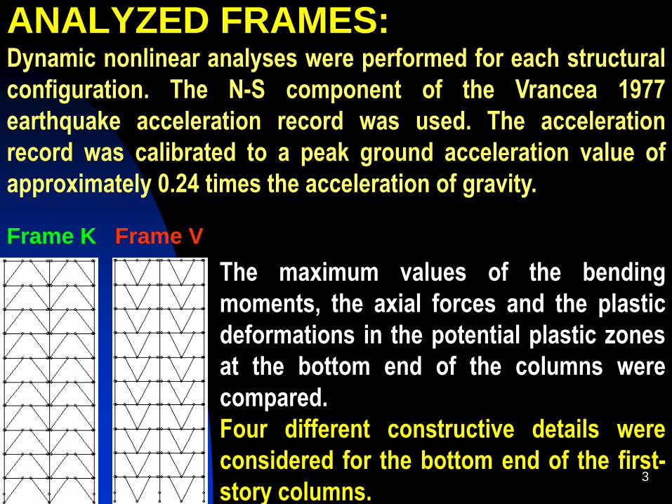
ANALYZED FRAMES: Dynamic nonlinear analyses were performed for each structural
configuration. The N-S component of the Vrancea 1977
earthquake acceleration record was used. The acceleration
record was calibrated to a peak ground acceleration value of
approximately 0.24 times the acceleration of gravity.
The maximum values of the bending
moments, the axial forces and the plastic
deformations in the potential plastic zones
at the bottom end of the columns were
compared.
Four different constructive details were
considered for the bottom end of the first-
story columns.
Frame K Frame V

4
Configuration 1:
Configuration 1 is the
reference analysis detail.
The column has the same
cross-section on the entire
height of the first story
column.
Transversal web stiffeners
(P3) were used to avoid early
local buckling in the
potentially plastic zone.

5
Configuration 2: In the second considered detail an
additional longitudinal stiffener (P4)
was placed on the web. This pair of
stiffeners was used to reduce the
axial loading level in the flanges, to
make room for stresses generated by
bending moment.
Plates P5 were placed to facilitate the
axial load transfer from the column
flanges (P1) to the longitudinal web
stiffeners (P4) reducing at the same
time load concentrating effects.
Transversal web stiffeners (P3) are
kept in all configurations to reduce
the risk of local buckling in the
potentially plastic zone .

6
Configuration 3:
The third configuration has a
reduced flange cross-section in the
potentially plastic zone
(resembling to dog-bone detail).
In configuration 3 the reduced
width of the flanges in the
potentially plastic zone is about
25% smaller than the flanges width
in the rest of the first-story column.
The longitudinal web stiffeners
were kept to assure about the
same axial capacity all along the
first-story column height.

7
Configuration 4: In the fourth considered detail the
first configuration column cross-
section was kept for the potentially
plastic zone, whereas the rest of
the column has larger flanges in
order to increase the buckling
capacity of the first-story column.
The reduced flange width in the
potentially plastic zone is also
about 25% smaller than the flange
width in the rest of the first-story
column.
All connections between structural
members, as well as the
connections to the infrastructure
were considered as fixed.

8
Forces at the bottom of the columns
The maximum bending moments recorded during
the dynamic nonlinear analyses at the bottom of the
columns in the other considered configurations are
nearly the same. Compared to these values, the
bending moments registered for configuration 3 are
about 20 ÷ 26% smaller.
The maximum axial forces recorded in the first-story
columns during dynamic nonlinear analyses are
quite the same for all considered configurations. It
seems that the considered constructive details do
not affect significant the values of the maximum
axial forces noticed in the first-story column.
Configuration 3 (with reduced column flanges in the potentially
plastic zones) leads to the smallest bending moment values at
the bottom end of the first-story columns.

9
Maximum bending moments at the bottom of the first-story columns
Frame K Bending moments marginal columns
0
2000
4000
6000
8000
(kNm)
(kNm) 7437.82 7658.72 6212.11 7483.31
Config. 1 Config. 2 Config. 3 Config. 4
Frame K Bending moments central columns
0
250
500
750
1000
(kNm)
(kNm) 902.31 901.49 715.06 898.17
Config. 1 Config. 2 Config. 3 Config. 4
Frame V
Bending moments marginal columns
0
2000
4000
6000
8000
(kNm)
(kNm) 6742.01 7067.41 5700.23 6783.2
Config. 1 Config. 2 Config. 3 Config. 4
Frame V
Bending moments marginal columns
0
450
900
1350
1800
(kNm)
(kNm) 1669.28 1671.91 1395.34 1685.3
Config. 1 Config. 2 Config. 3 Config. 4

10
Buckling resistance of first-story columns
The buckling resistance of first-story columns was evaluated
using relations (6.61, 6.62) and annex B from EN 1993-1-1:2005 .
It can be observed from the graphics in the figure below, that
configuration 4 provides the greatest buckling resistance for the
situations when inelastic deformations appear in the potentially
plastic zones at the bottom of the columns.
0.00
0.20
0.40
0.60
0.80
1.00
(Loading
State/
Capacity)
Frame V Marginal Columns
General Stability Criterion
Loading State/ Capacity 0.984 1.060 0.877 0.828
Config. 1 Config. 2 Config. 3 Config. 40.00
0.20
0.40
0.60
0.80
1.00
(Loading
State/
Capacity)
Frame K Central Columns
General Stability Criterion
Loading State/ Capacity 1.018 0.995 0.897 0.821
Config. 1 Config. 2 Config. 3 Config. 4

11
Maximum plastic hinge rotations
The greatest plastic hinge rotations in the
potentially plastic zones of the first-story
columns were recorded during dynamic
nonlinear analyses for configuration 3.
The values of the maximum plastic hinge
rotations at the bottom of the columns for
the other considered configurations were in
the same range. Compared to these values,
the plastic rotations for configuration 3
were about 37 ÷ 45% greater.

12
Maximum plastic hinge rotations
0
0.003
0.006
0.009
0.012
(rad)
Frame K - Marginal Columns
Maximum plastic hinge rotations
(radians) 0.009208 0.008734 0.013296 0.009415
Config. 1 Config. 2 Config. 3 Config. 40
0.003
0.006
0.009
0.012
(rad)
Frame K - Central Columns
Maximum plastic hinge rotations
(radians) 0.00982 0.009289 0.01393 0.010456
Config. 1 Config. 2 Config. 3 Config. 4
0
0.003
0.006
0.009
0.012
(rad)
Frame V - Marginal Columns
Maximum plastic hinge rotations
(radians) 0.008336 0.007993 0.011648 0.008597
Config. 1 Config. 2 Config. 3 Config. 40
0.003
0.006
0.009
0.012
(rad)
Frame V - Central Columns
Maximum plastic hinge rotations
(radians) 0.008782 0.008402 0.012022 0.00904
Config. 1 Config. 2 Config. 3 Config. 4

13
Conclusions Compared to the other
considered constructive
details, configuration 3
leads to smaller bending
moments and greater
plastic hinges rotations at
the bottom of the columns.
The smaller bending
moment values conduct to
smaller anchor bolts for
the columns.

14
Conclusions
Configuration 4 appears to
be the safest from the
point of view of assuring
the general stability of the
first-story column in the
situation when plastic
deformations occur in the
potentially plastic zone at
the bottom of the column.

15
Conclusions
In configuration 3 and 4 the distribution of
plastic deformations along the first-story
columns is better controlled. The inelastic
deformations along the first-story column are
concentrated mainly in the column segments
with reduced flanges width.
Config. 3 Config. 4
16
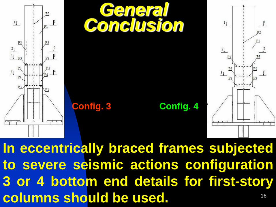
General Conclusion
In eccentrically braced frames subjected
to severe seismic actions configuration
3 or 4 bottom end details for first-story
columns should be used.
Config. 3 Config. 4

17
Thank you very much for your
attention