power+ - mastec age online double conversion ups...4.2. dc distribution panel cabling ... power...
TRANSCRIPT
Gamatronic Electronic Industries Ltd.
Har Hotzvim Industrial Park, 14 Hartum St., PO Box 45029, Jerusalem 97774, Israel
Tel: +972-2-588-8222 Fax: +972-2-582-8875
Email: [email protected] web: www.gamatronic.com
PPOOWWEERR++ UUsseerr GGuuiiddee aanndd IInnssttrruuccttiioonn MMaannuuaall
Release 1.6
February 2004
Gamatronic Electronic Industries Ltd. User Guide
Power+ User Guide & Instruction Manual Page i
Gamatronic Electronic Industries Ltd. Har Hotzvim Industrial Park 14 Hartum St. PO Box 45029 Jerusalem 97774 Israel Tel: +972-2-588-8222 Fax: +972-2-582-8875
Email: [email protected] Website: www.gamatronic.com
Copyright by Gamatronic Electronic Industries Ltd., 2004. All rights reserved worldwide. The information contained in this document is proprietary and is subject to all relevant copyright, patent and other laws protecting intellectual property, as well as any specific agreement protecting Gamatronic Electronic Industries Ltd. rights in the aforesaid information. Neither this document nor the information contained herein may be published, or reproduced, in whole or in part, without the express, prior, written permission of Gamatronic Electronic Industries Ltd. In addition, any use of this document or the information contained herein for any purposes other than those for which it was disclosed is strictly forbidden.
Gamatronic Electronic Industries Ltd. reserves the right, without prior notice or liability, to make changes in equipment design or specifications.
Information supplied by Gamatronic Electronic Industries Ltd. is believed to be accurate and reliable. However, no responsibility is assumed by Gamatronic Electronic Industries Ltd. for the use thereof nor for the rights of third parties which may be affected in any way by the use thereof.
Any representation(s) in this document concerning performance of Gamatronic Electronic Industries Ltd. product(s) are for informational purposes only and are not warranties of future performance, either express or implied. Gamatronic Electronic Industries Ltd. standard limited warranty, available upon request, stated in its sales contract or order confirmation form, is the only warranty offered by Gamatronic Electronic Industries Ltd. in relation thereto. This document may contain flaws, omissions or typesetting errors; no warranty is granted nor liability assumed in relation thereto unless specifically undertaken in Gamatronic Electronic Industries Ltd. sales contract or order confirmation. Information contained herein is periodically updated and changes will be incorporated into subsequent editions. If you have encountered an error, please notify Gamatronic Electronic Industries Ltd. All specifications are subject to change without prior notice.
User Guide Gamatronic Electronic Industries Ltd.
Page ii Power+ User Guide & Instruction Manual 1.6
TABLE OF CONTENTS 1. SYSTEM FEATURES...........................................................................................................1 2. INTRODUCTION ..................................................................................................................2
2.1. System Overview .....................................................................................................2 3. SYSTEM DESCRIPTION......................................................................................................6
3.1. UPS Basic Module (10kVA / 8KW) ..........................................................................6 3.1.1. Single UPS Module Specifications......................................................11
3.2. UPS System Controller..........................................................................................13 3.2.1. System Controller Specifications........................................................14
3.3. Static Switch (ST/SW) Module ..............................................................................15 3.4. Batteries and Configurations................................................................................17
3.4.1. Internal Batteries...................................................................................17 3.4.2. External Batteries..................................................................................19
3.5. CABLING and CONNECTIONS..............................................................................19 3.5.1. UPS Module – Connectors Description ..............................................20 3.5.2. UPS Module Pin Assignment Table ....................................................22
4. SYSTEM DESCRIPTION....................................................................................................24 4.1. System Cabling ......................................................................................................25 4.2. DC Distribution Panel Cabling..............................................................................27 4.3. AC Input Fuses.......................................................................................................28 4.4. AC Distribution Compartment ..............................................................................29 4.5. AC Input/Output Main Terminals ..........................................................................29 4.6. DC Fuse Section.....................................................................................................30 4.7. Static Switch Connections....................................................................................32 4.8. System Controller Connections ...........................................................................33 4.9. Using the Dry Contacts Plug.................................................................................35 4.10. Setting the Shelf Address .....................................................................................36 4.11. Adding a module to an existing system ..............................................................38
5. SYSTEM INSTALLATION..................................................................................................39 5.1. Installation and Start-up Sequence......................................................................41 5.2. Using the System Controller.................................................................................42
5.2.1. Setting the Number of UPS Modules in a System .............................44 5.3. Retrieving History (LOG of Events)......................................................................46 5.4. Control Communications ......................................................................................46 5.5. System Controller Alarms.....................................................................................47
6. TROUBLESHOOTING .......................................................................................................48 7. SYSTEM CONTROLLER AND COMMUNICATIONS .......................................................50
7.1. Introduction ............................................................................................................50 7.2. SCC POWER+ characteristics ..............................................................................50 7.3. Controller User Interface.......................................................................................51 7.4. Service Utilities ......................................................................................................51
7.4.1. Start-up Screens ...................................................................................51 7.4.2. The Main Menu ......................................................................................54
8. SETUP PROCEDURES......................................................................................................55 8.1. Setting Alarm Thresholds .....................................................................................55
8.1.1. Setting Alarm Vibration Parameters ...................................................55 8.1.2. Setting the Integration Factor for Alarms...........................................56 8.1.3. 'Auto' Test Batteries .............................................................................56
8.2. Setting Password Level 1......................................................................................56 9. USING SERVICE PROGRAMS .........................................................................................57
9.1. Access to Service Mode........................................................................................57 9.2. Selecting the Controller’s Low Level Utilities.....................................................57 9.3. Setting the Network Addresses............................................................................58
9.3.1. Setting the SNMP Factor ......................................................................58 9.4. Configuring Dry Contacts and Alarms.................................................................58
9.4.1. Linking Alarms to Dry Contacts ..........................................................58 9.4.2. Linking Alarms to Severity Levels.......................................................58
9.5. Calibrating Measurements ....................................................................................58
Gamatronic Electronic Industries Ltd. User Guide
Power+ User Guide & Instruction Manual 1.6 Page iii
9.6. Controller Self-Test................................................................................................59 9.7. Battery Test ............................................................................................................59
9.7.1. Periodic/Automatic Battery Test .........................................................59 10. MONITORING THE SYSTEM ............................................................................................60
10.1. Power Meter............................................................................................................60 10.2. System Operating Times.......................................................................................61 10.3. Main DIP Switch Status .........................................................................................61 10.4. Panel and Slave DIP Switch Status......................................................................61 10.5. SC POWER+ Internal Power Supply ....................................................................62 10.6. System Temperature..............................................................................................62 10.7. Internal Communication........................................................................................62
11. MONITORING SYSTEM COMPONENTS..........................................................................63 11.1. Monitoring the Batteries........................................................................................63
11.1.1. Battery Test Progress...........................................................................63 11.2. Monitoring Alarms .................................................................................................63
12. REMOTE CONTROL..........................................................................................................65 12.1. WING CONFIGURATIONS .....................................................................................66
13. SC POWER+ NET LOGS...................................................................................................68 14. SYSTEM SPECIFICATIONS..............................................................................................69 15. ORDERING INFORMATION ..............................................................................................71
User Guide Gamatronic Electronic Industries Ltd.
Page iv Power+ User Guide & Instruction Manual 1.6
LIST OF FIGURES Figure 1: Block diagram ...........................................................................................................2 Figure 2: Sub-assemblies ........................................................................................................3 Figure 3: 10kVA configuration.................................................................................................3 Figure 4: 50kVA configuration.................................................................................................4 Figure 5: 100kVA configuration...............................................................................................4 Figure 6: 40kVA configuration - Small enough to fit in a 4-passenger elevator ................5 Figure 7: Single UPS Module- Front/Rear View .....................................................................6 Figure 8: Single UPS Module Block Diagram.........................................................................7 Figure 9: Power section of the PFC in a single UPS module ...............................................8 Figure 10: Input currents of the PFC (without filters) ...........................................................8 Figure 11: PFC control scheme.............................................................................................10 Figure 12: DC/AC inverter principal topology......................................................................11 Figure 13: System controller - Front panel...........................................................................13 Figure 14: System controller - Block diagram .....................................................................14 Figure 15: ST/SW front panel view ........................................................................................16 Figure 16: ST/SW block diagram...........................................................................................16 Figure 17: 3-Phase ST/SW block diagram ............................................................................17 Figure 18: 40kVA N+1 System with Internal Batteries ........................................................18 Figure 19: Internal Battery Drawer – Exploded View...........................................................18 Figure 20: Schematic of a 30kVA POWER+ system ............................................................20 Figure 21: UPS module – Rear view......................................................................................21 Figure 22: UPS module connectors - Pin assignments ......................................................21 Figure 23: Power+ system - Modular structure ...................................................................24 Figure 24: POWER+ System - Rear View..............................................................................25 Figure 25: Control PCB and flat cable ..................................................................................26 Figure 26: Battery connections .............................................................................................27 Figure 27: UPS modules - AC input fuses............................................................................28 Figure 28: AC input fuses and assignments........................................................................28 Figure 29: AC distribution......................................................................................................29 Figure 30: Input & output main terminals.............................................................................30 Figure 31: DC Fuse section....................................................................................................31 Figure 32: Static switch terminals – Rear view....................................................................32 Figure 33: Static switch location in a rack ...........................................................................33 Figure 34: System controller rear view mounted on a shelf ..............................................34 Figure 35: System controller outside the shelf - Rear view ...............................................34 Figure 36: Close view of the dry contacts plug ...................................................................34 Figure 37: Connecting the indicator switch.........................................................................35 Figure 38: Control PCB on a shelf – General view ..............................................................36 Figure 39: DIP switch – Close-up ..........................................................................................37 Figure 40: DIP switch settings...............................................................................................38 Figure 41: POWER+ cabling...................................................................................................39 Figure 42: Normal display of the controller LCD .................................................................41 Figure 43: Controller menu #1 ...............................................................................................42 Figure 44: System DC voltages .............................................................................................42 Figure 45: Overall phase voltages/currents .........................................................................43 Figure 46: Power factor 0 .......................................................................................................43 Figure 47: Power factor 0.5 ....................................................................................................43 Figure 48: Power factor 1 .......................................................................................................43 Figure 49: LCD Panel - Selection...........................................................................................44 Figure 50: Module phase voltages/currents.........................................................................44 Figure 51: Battery voltages....................................................................................................44 Figure 52: Controller menu #2 ...............................................................................................45 Figure 53: Controller menu #3 ...............................................................................................45 Figure 54: Controller menu #4 ...............................................................................................45 Figure 55: Number of UPS modules......................................................................................45 Figure 56: Log display............................................................................................................46 Figure 57: Communications...................................................................................................46
Gamatronic Electronic Industries Ltd. User Guide
Power+ User Guide & Instruction Manual 1.6 Page v
Figure 58: UPS module front panel .......................................................................................48 Figure 59: Key panel ...............................................................................................................60 Figure 60: WING – General Block Diagram ..........................................................................65 Figure 61: WING Optional Configurations...........................................................................67
LIST OF TABLES Table 1: Single UPS Module Specifications .........................................................................11 Table 2: System controller specifications............................................................................14 Table 3: UPS module pin assignment and function............................................................22 Table 4: DIP switch setup in a 100kVA system (X = don't care). .......................................38 Table 5: Wire currents and recommended gauge for 20-100kVA installation..................40 Table 6: UPS Module Indicators ............................................................................................49 Table 7: Specifications – Part 1 .............................................................................................69 Table 8: Specifications – Part 2 .............................................................................................70 Table 9: Battery Specifications..............................................................................................70

Gamatronic Electronic Industries Ltd.
Power+ User Guide & Instruction Manual 1.6 Page 1
1. SYSTEM FEATURES The POWER + has many unique features:
POWER+ is a 1 or 3-phase online-battery system
POWER+ can be configured as 1/1, 3/1 or 3/3 system
POWER+ is modular; it may include from 1 to 10 modules
POWER+ can provide from 10 to 100kVA of “clean” power to your loads
POWER+ is redundant and upgradeable, upgrade as you grow!
POWER+ is reliable thanks to its N+ 1 redundancy
POWER+ shares the battery bank
POWER+ has active current sharing at the input / output
POWER+ has a common output transformer that may be removed if necessary
POWER+ is a "green" power solution thanks to THD of 5% at the input
POWER+ is a unity PF solution (Input PF=1)
POWER+ operates in Continuous Current Mode (CCM) which reduces line interferences (RFI / EMI)
POWER+ is light and small, a basic 10kVA module weighs only 9.5Kg
POWER+ is easily maintained at module level
POWER+ UPS employs a system controller for diagnostics and communications
POWER+ UPS contains a centralized static switch module
POWER+ UPS even includes a self-contained performance analyzer
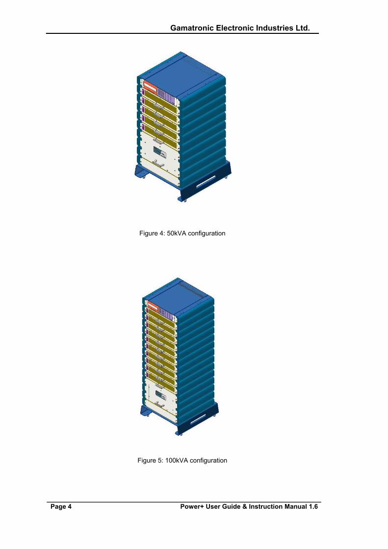
The POWER+ is flexible in structure, allowing it to be easily extended by adding modules as required. The battery bank is common to all modules and may comprise one or more branches to include a redundant battery if desired. The system can work perfectly without the system controller, although measurements and other functions are then disabled. The system controller is not mandatory for operation of the UPS. The UPS modules are designed for hot swapping, making many different system configurations possible. See Figure 2 through Figure 5, below.
Gamatronic Electronic Industries Ltd.
Page 2 Power+ User Guide & Instruction Manual 1.6
2. INTRODUCTION
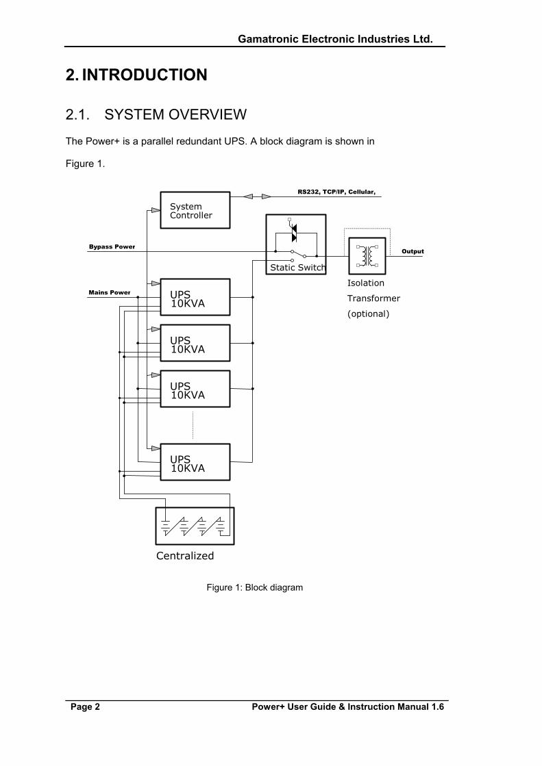
2.1. SYSTEM OVERVIEW
The Power+ is a parallel redundant UPS. A block diagram is shown in
Figure 1.
UPS 10KVA
UPS 10KVA
Static Switch
RS232, TCP/IP, Cellular,
Centralized
UPS 10KVA
Mains Power
Output
Isolation
Transformer (optional)
Bypass Power
UPS 10KVA
SystemController
Figure 1: Block diagram
Gamatronic Electronic Industries Ltd.
Power+ User Guide & Instruction Manual 1.6 Page 3
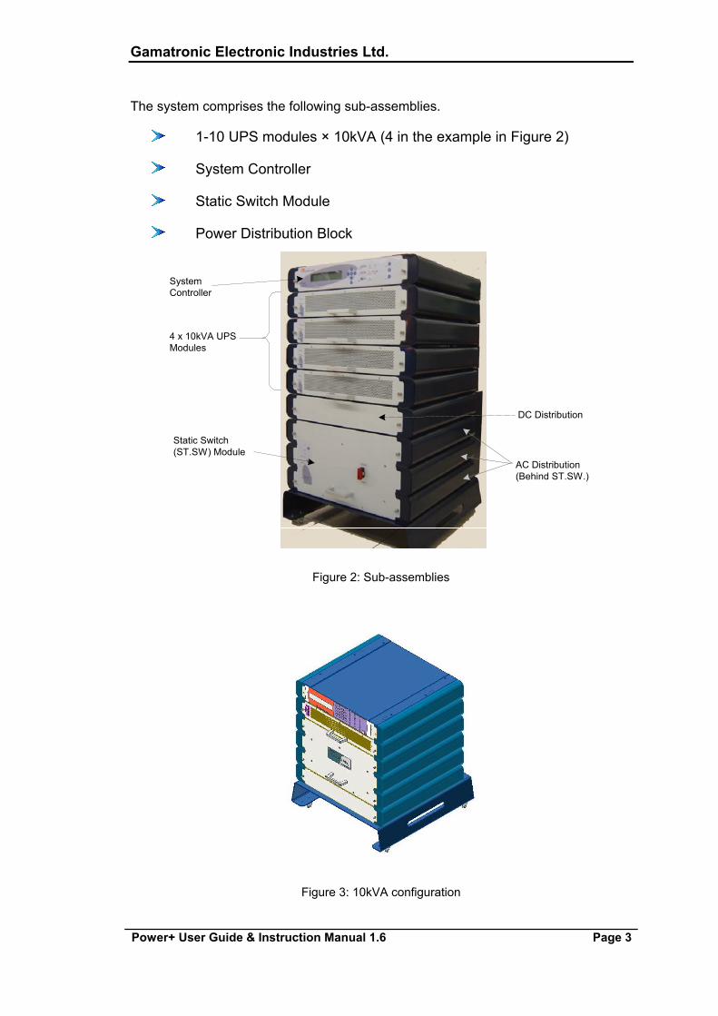
The system comprises the following sub-assemblies.
1-10 UPS modules × 10kVA (4 in the example in Figure 2)
System Controller
Static Switch Module
Power Distribution Block
SystemController
4 x 10kVA UPSModules
Static Switch(ST.SW) Module
DC Distribution
AC Distribution(Behind ST.SW.)
Figure 2: Sub-assemblies
Figure 3: 10kVA configuration
Gamatronic Electronic Industries Ltd.
Page 4 Power+ User Guide & Instruction Manual 1.6
Figure 4: 50kVA configuration
Figure 5: 100kVA configuration
Gamatronic Electronic Industries Ltd.
Power+ User Guide & Instruction Manual 1.6 Page 5
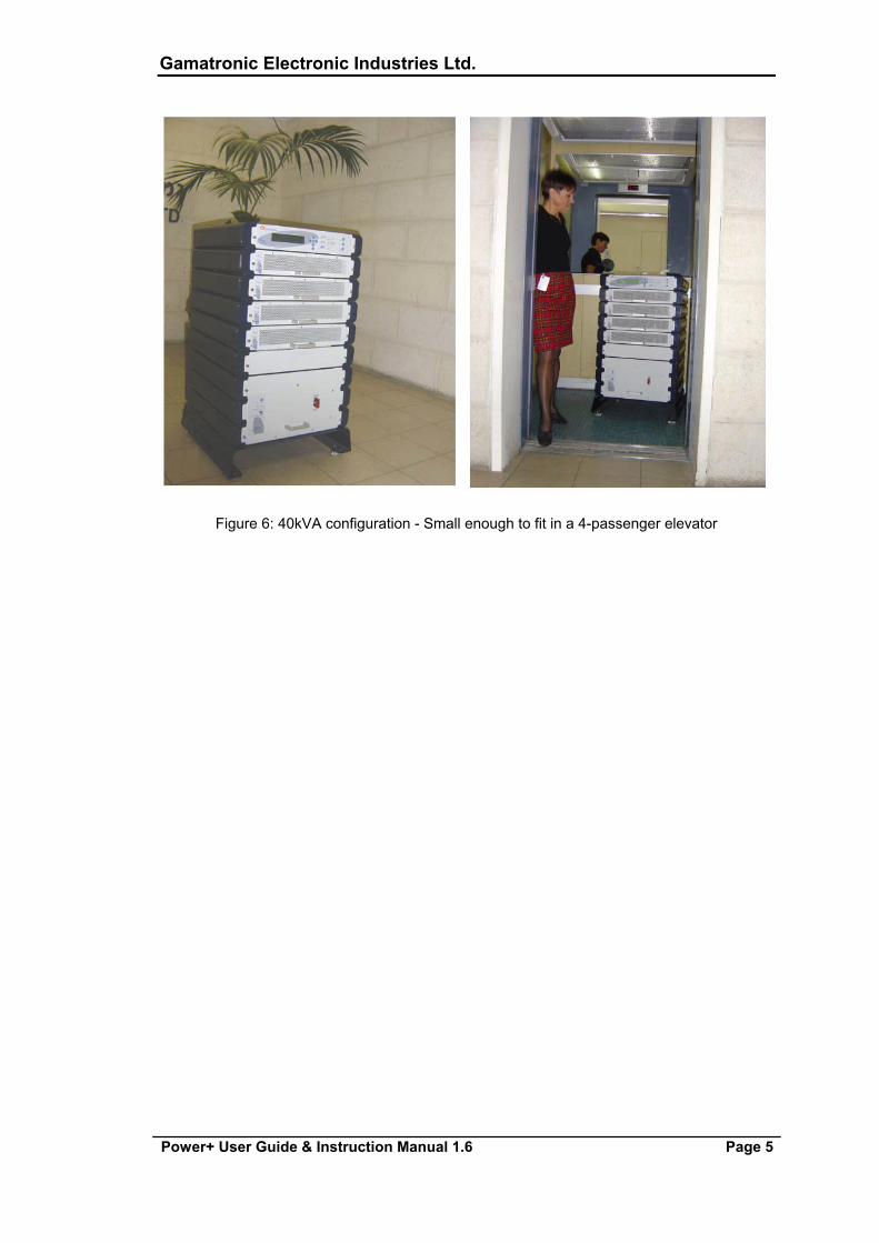
Figure 6: 40kVA configuration - Small enough to fit in a 4-passenger elevator

Gamatronic Electronic Industries Ltd.
Page 6 Power+ User Guide & Instruction Manual 1.6
3. SYSTEM DESCRIPTION
3.1. UPS BASIC MODULE (10KVA / 8KW)
The UPS Basic Module is the core of the system, which comprises 1 to 10 identical parallel modules depending on capacity requirements.
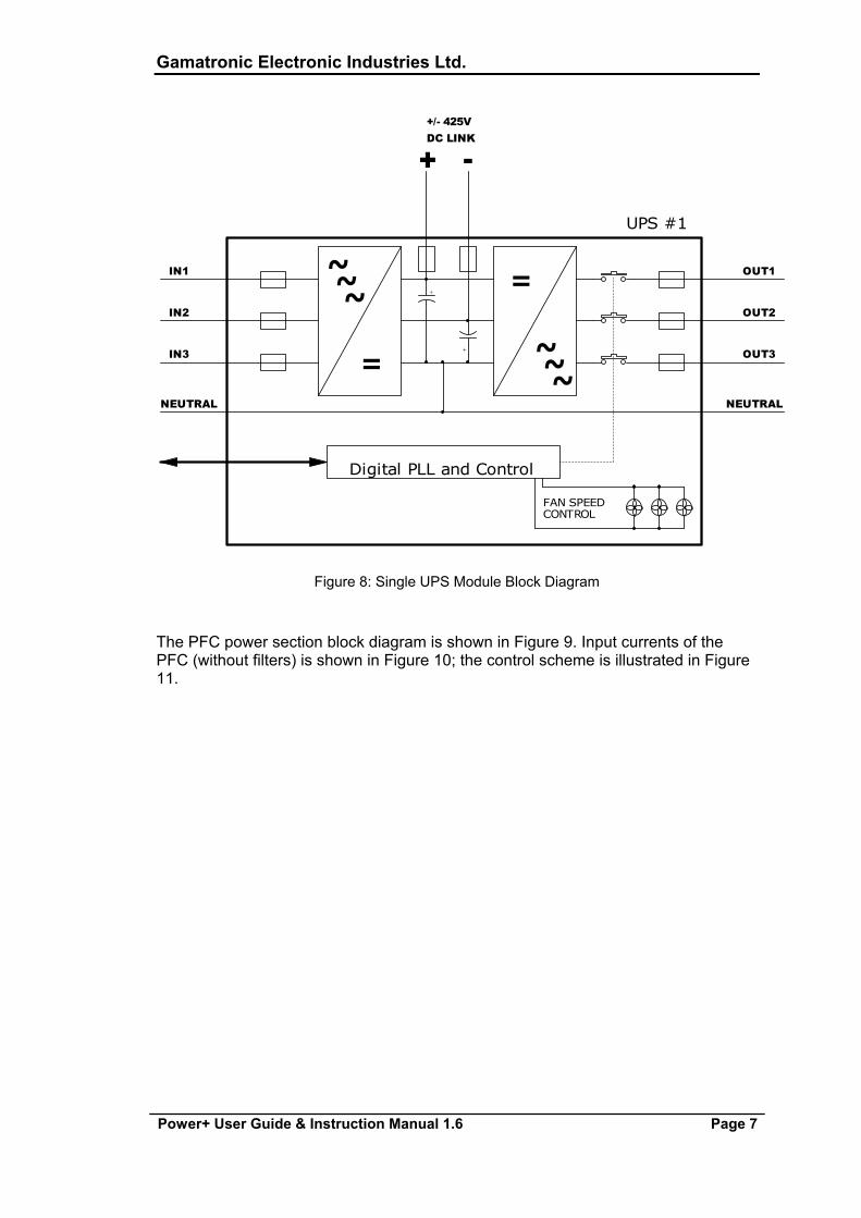
A general module view is shown in Figure 7. The module classic on-line double-conversion type block diagram is illustrated in Figure 8.
This design has proved to be very stable. No transfer time is required for the UPS to switch from normal to backup mode; the load is supplied constantly by stable and clean power. A Power Factor Correction (PFC)1 is responsible for the low Total Harmonic Distortion (THD) and unity Power Factor (PF) at the input.
The input voltage(s) is converted to a stable ±425V at the DC link.
This stage can maintain current sharing between the three input phases as well as among other parallel units, because of the current sharing signal that it produces.
Figure 7: Single UPS Module- Front/Rear View
1 PFC is a feature included that reduces the amount of generated reactive power. Reactive power operates at right angles to true power and energizes the magnetic field. Reactive power has no real value for an electronic device, but electric companies charge for both true and reactive power resulting in unnecessary charges. In power factor correction, the power factor (represented as "k") is the ratio of true power (kwatts) divided by reactive power (kvar). The power factor value is between 0.0 and 1.00. If the power factor is above 0.8, the device is using power efficiently. A standard power supply has a power factor of 0.70-0.75, and a power supply with PFC has a power factor of 0.95-0.99.
Gamatronic Electronic Industries Ltd.
Power+ User Guide & Instruction Manual 1.6 Page 7
~
+
~
IN2
-
~IN3
DC LINK
NEUTRAL
+/- 425V
+
OUT2~
NEUTRAL
=
Digital PLL and Control
UPS #1
FAN SPEEDCONTROL
OUT3
~
+
~=IN1 OUT1
Figure 8: Single UPS Module Block Diagram
The PFC power section block diagram is shown in Figure 9. Input currents of the PFC (without filters) is shown in Figure 10; the control scheme is illustrated in Figure 11.
Gamatronic Electronic Industries Ltd.
Page 8 Power+ User Guide & Instruction Manual 1.6
-
+
T
Control
-
+
+
Ir+
Control
Is
Control
N
-
+
R S
It
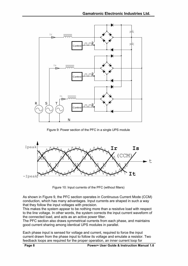
Figure 9: Power section of the PFC in a single UPS module
Ir Is
It
(CCM)t
-Ipeak
Ipeak
Figure 10: Input currents of the PFC (without filters)
As shown in Figure 9, the PFC section operates in Continuous Current Mode (CCM) conduction, which has many advantages. Input currents are shaped in such a way that they follow the input voltages with precision. This makes the system appear to be nothing more than a resistive load with respect to the line voltage. In other words, the system corrects the input current waveform of the connected load, and acts as an active power filter. The PFC section also draws symmetrical currents from each phase, and maintains good current sharing among identical UPS modules in parallel.
Each phase input is sensed for voltage and current, required to force the input current drawn from the phase input to follow its voltage and emulate a resistor. Two feedback loops are required for the proper operation, an inner current loop for
Gamatronic Electronic Industries Ltd.
Power+ User Guide & Instruction Manual 1.6 Page 9
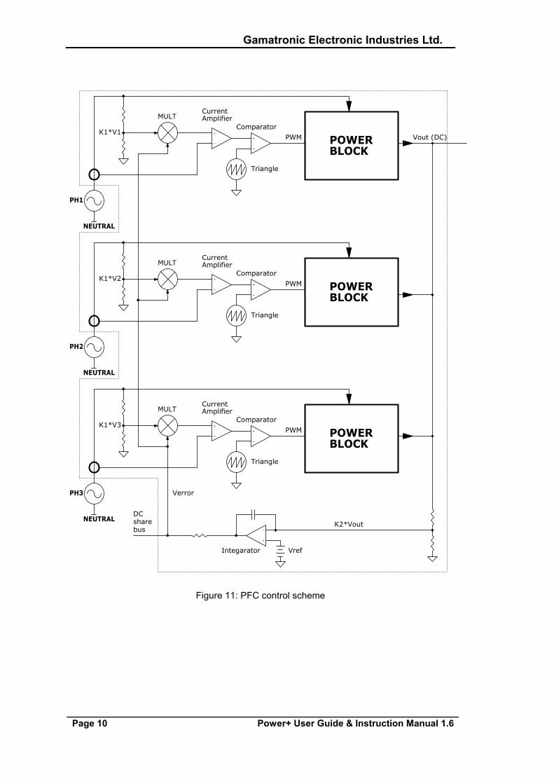
maintaining a correct wave shape and an outer voltage loop to ensure a correct DC output level.
The voltage sample (k*Vin) is multiplied by the error voltage from a common voltage feedback amplifier (Integrator). The result is than compared to the actual sampled phase current which forces the current amplifier current to follow the phase input voltage. The output of the integrator is connected to a current sharing bus causing all other modules to be connected to this bus via the same resistor. This ensures that all the multipliers of each UPS module receive the same input and all that modules are equally loaded.
Gamatronic Electronic Industries Ltd.
Page 10 Power+ User Guide & Instruction Manual 1.6
K2*Vout
Comparator
Triangle
NEUTRAL
MULT
Triangle
PWM
Comparator
Integarator
PH1
NEUTRAL
CurrentAmplifier
CurrentAmplifier
+
-
Vout (DC)
+
-
POWERBLOCK
NEUTRAL
Comparator
POWERBLOCK
Triangle
+
-
MULT
K1*V1POWERBLOCK
PWM+
-
+
-
K1*V3
CurrentAmplifier
+
-
K1*V2
PH3
Vref
PWM
MULT
Verror
PH2
DCsharebus
+
-
Figure 11: PFC control scheme
Gamatronic Electronic Industries Ltd.
Power+ User Guide & Instruction Manual 1.6 Page 11
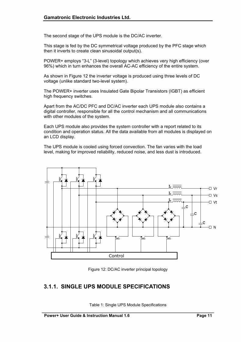
The second stage of the UPS module is the DC/AC inverter.
This stage is fed by the DC symmetrical voltage produced by the PFC stage which then it inverts to create clean sinusoidal output(s).
POWER+ employs “3-L” (3-level) topology which achieves very high efficiency (over 96%) which in turn enhances the overall AC-AC efficiency of the entire system.
As shown in Figure 12 the inverter voltage is produced using three levels of DC voltage (unlike standard two-level system).
The POWER+ inverter uses Insulated Gate Bipolar Transistors (IGBT) as efficient high frequency switches.
Apart from the AC/DC PFC and DC/AC inverter each UPS module also contains a digital controller, responsible for all the control mechanism and all communications with other modules of the system.
Each UPS module also provides the system controller with a report related to its condition and operation status. All the data available from all modules is displayed on an LCD display.
The UPS module is cooled using forced convection. The fan varies with the load level, making for improved reliability, reduced noise, and less dust is introduced.
Vr
C
Vs
C
Vt
+
N
- +- +
+
C
- +
L
L
Control
L
Figure 12: DC/AC inverter principal topology
3.1.1. SINGLE UPS MODULE SPECIFICATIONS
Table 1: Single UPS Module Specifications

Gamatronic Electronic Industries Ltd.
Page 12 Power+ User Guide & Instruction Manual 1.6
TECHNICAL DATA – UPS MODULE Output Rated Power 10kVA/8KW Topology Online Battery, Double Conversion Construction Modular parallel hot-plugged modules Input Voltage (V) 3 × 400+N (3 × 230V) Input Voltage range (%) + 15 – 25 Input Current (A) 15A Input Frequency (Hz) 47-63Hz Frequency tracking range (Hz) ±1, ±2, ±3 (selectable) Output slew rate 1 Hz/sec Power walk-in (sec) > 60 Input Power Factor 0.99 Input THDI (%) 5 Output Voltage (V) 3 × 400+N (3 × 230V) Output Static Regulation ±1% Output Regulation for unbalanced load ±1% for 100% unbalanced load Dynamic response to 100% load step 2%
110% for 10 minutes 125% for 60 seconds
Overload
1000% for 1 cycle Output Waveform Sinusoidal Output THD (%) Less than 2 for linear load Load CF ≤ 5 Fuse clearance capability Input, Output, DC link AC-AC efficiency (nominal) 95% at full load Maximum power dissipation (Po=8KW) 421W (1437 BTU)
-10 to +40 (operating) Ambient temperature (ºC) -20 to +60 (storage)
Relative humidity (%) 95 max non-condensation Altitude (m) 1500 w/o de-rating DC-Link Voltage ±340V to ±425V Cooling system Multi-Fan with speed control (forced) Dimensions (mm) 19"(W), 2U(H), 455(D) – Excluding shelf Weight 9.5Kg
Gamatronic Electronic Industries Ltd.
Power+ User Guide & Instruction Manual 1.6 Page 13
3.2. UPS SYSTEM CONTROLLER
The POWER+ system controller is designed primarily for monitoring, diagnostics and communications.
Some other useful features include temperature compensation of the battery voltage.
The POWER+ can work without the system controller but with reduced functionality.
Figure 14 shows the system controller block diagram. The core of the controller is a powerful embedded micro-controller, surrounded by many peripherals (analog, digital, communication).
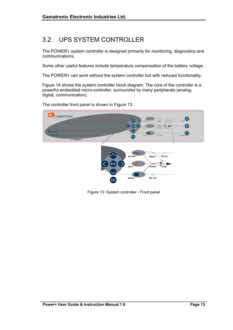
The controller front panel is shown in Figure 13.
Figure 13: System controller - Front panel

Gamatronic Electronic Industries Ltd.
Page 14 Power+ User Guide & Instruction Manual 1.6
Figure 14: System controller - Block diagram
3.2.1. SYSTEM CONTROLLER SPECIFICATIONS Table 2: System controller specifications
TECHNICAL DATA – SYSTEM CONTROLLER Micro Controller core 16 bit Display 4 x 40 characters LCD with backlight Other indicators 8 LED’s, buzzer Analog input channels 4 Digital input channels 8 Real Time Clock (RTC) Yes, with backup Power meter kVA, kW, PF Volt-free outputs (dry contacts) 6 RS232 user port Yes, isolated Optional communication TCP/IP, GPRS/SMS Wireless
communication (Optional) Communications with system modules Serial, isolated Events log 255 events
Gamatronic Electronic Industries Ltd.
Power+ User Guide & Instruction Manual 1.6 Page 15
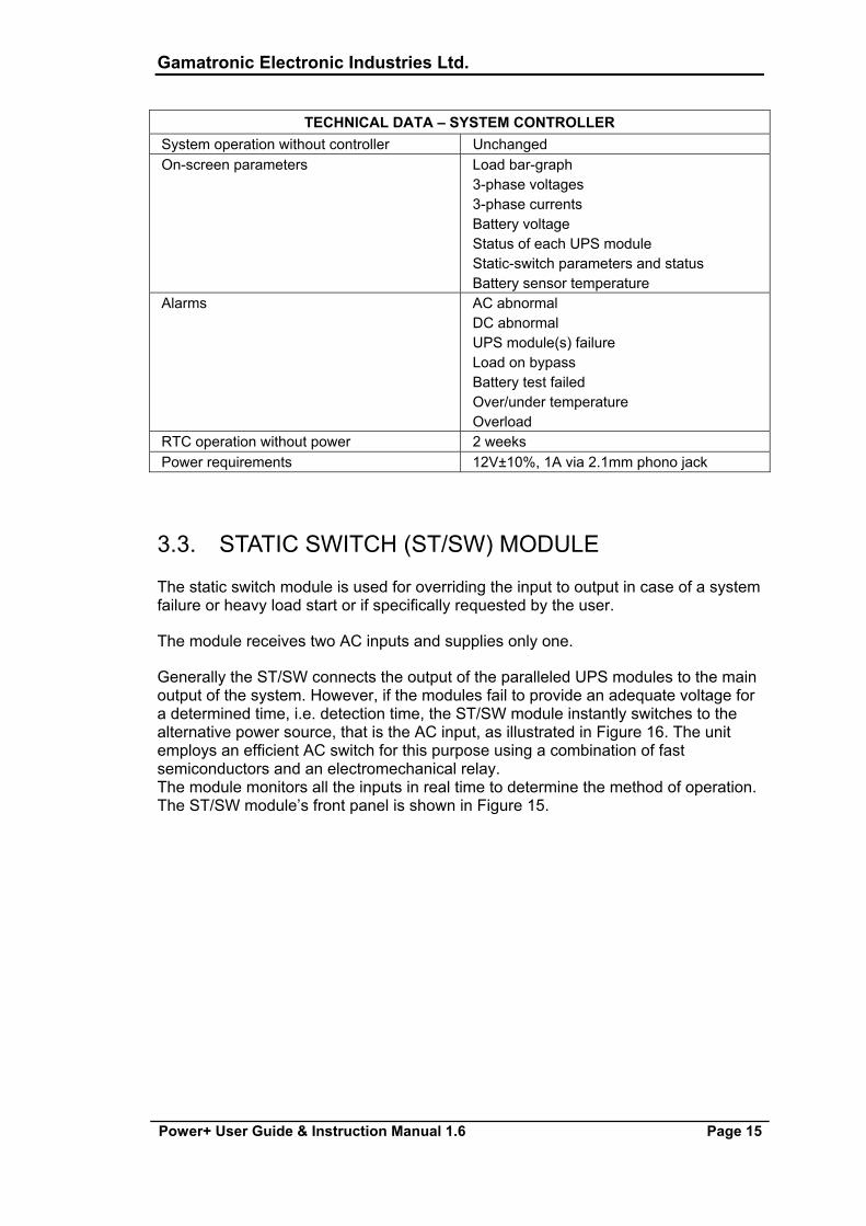
TECHNICAL DATA – SYSTEM CONTROLLER System operation without controller Unchanged On-screen parameters Load bar-graph
3-phase voltages 3-phase currents Battery voltage Status of each UPS module Static-switch parameters and status Battery sensor temperature
Alarms AC abnormal DC abnormal UPS module(s) failure Load on bypass Battery test failed Over/under temperature Overload
RTC operation without power 2 weeks Power requirements 12V±10%, 1A via 2.1mm phono jack
3.3. STATIC SWITCH (ST/SW) MODULE
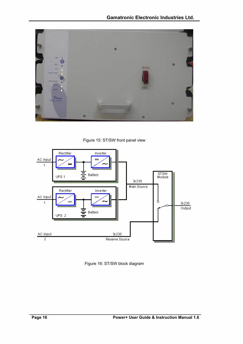
The static switch module is used for overriding the input to output in case of a system failure or heavy load start or if specifically requested by the user.
The module receives two AC inputs and supplies only one.
Generally the ST/SW connects the output of the paralleled UPS modules to the main output of the system. However, if the modules fail to provide an adequate voltage for a determined time, i.e. detection time, the ST/SW module instantly switches to the alternative power source, that is the AC input, as illustrated in Figure 16. The unit employs an efficient AC switch for this purpose using a combination of fast semiconductors and an electromechanical relay. The module monitors all the inputs in real time to determine the method of operation. The ST/SW module’s front panel is shown in Figure 15.
Gamatronic Electronic Industries Ltd.
Page 16 Power+ User Guide & Instruction Manual 1.6
Figure 15: ST/SW front panel view
Figure 16: ST/SW block diagram
Gamatronic Electronic Industries Ltd.
Power+ User Guide & Instruction Manual 1.6 Page 17
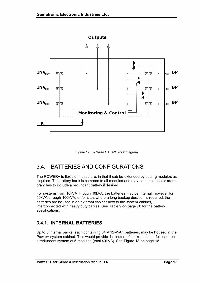
BP
BP
BP
INV
INV
Monitoring & Control
B
INV
Outputs
Figure 17: 3-Phase ST/SW block diagram
3.4. BATTERIES AND CONFIGURATIONS
The POWER+ is flexible in structure, in that it cab be extended by adding modules as required. The battery bank is common to all modules and may comprise one or more branches to include a redundant battery if desired.
For systems from 10kVA through 40kVA, the batteries may be internal, however for 50kVA through 100kVA, or for sites where a long backup duration is required, the batteries are housed in an external cabinet next to the system cabinet, interconnected with heavy duty cables. See Table 9 on page 70 for the battery specifications.
3.4.1. INTERNAL BATTERIES
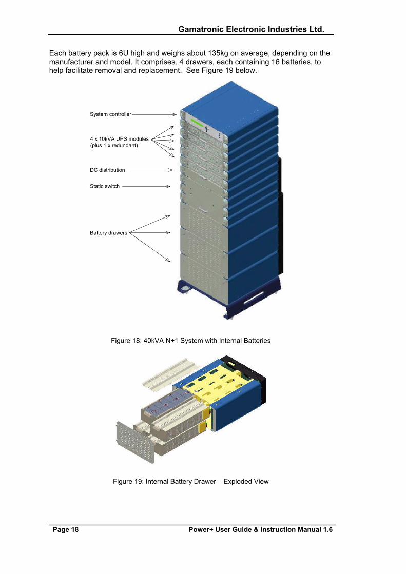
Up to 3 internal packs, each containing 64 × 12v/5Ah batteries, may be housed in the Power+ system cabinet. This would provide 4 minutes of backup time at full load, on a redundant system of 5 modules (total 40kVA). See Figure 18 on page 18.
Gamatronic Electronic Industries Ltd.
Page 18 Power+ User Guide & Instruction Manual 1.6
Each battery pack is 6U high and weighs about 135kg on average, depending on the manufacturer and model. It comprises. 4 drawers, each containing 16 batteries, to help facilitate removal and replacement. See Figure 19 below.
System controller
4 x 10kVA UPS modules(plus 1 x redundant)
DC distribution
Static switch
Battery drawers
Figure 18: 40kVA N+1 System with Internal Batteries
Figure 19: Internal Battery Drawer – Exploded View
Gamatronic Electronic Industries Ltd.
Power+ User Guide & Instruction Manual 1.6 Page 19
3.4.2. EXTERNAL BATTERIES
External batteries are housed in a separate cabinet. They employ batteries of a higher capacity and are used for extended backup time, and for larger systems ranging from 50kVA through 100kVA,.
These batteries are connected to the system by heavy duty cables, care must be taken to ensure correct polarity. Overall voltage may be as high as 870vDC + to -, i.e. +435vDC and –435vDC with respect to ground/earth. Precautionary measures should be taken whenever connecting battery circuit breakers.
See Figure 37 on page 35. This arrangement ensures equal sharing between all arms of the 3-phase circuit breaker, and that the tripping of either one of the poles (positive or negative) will eliminate the possibility of operation, regardless of the status of the other breaker.
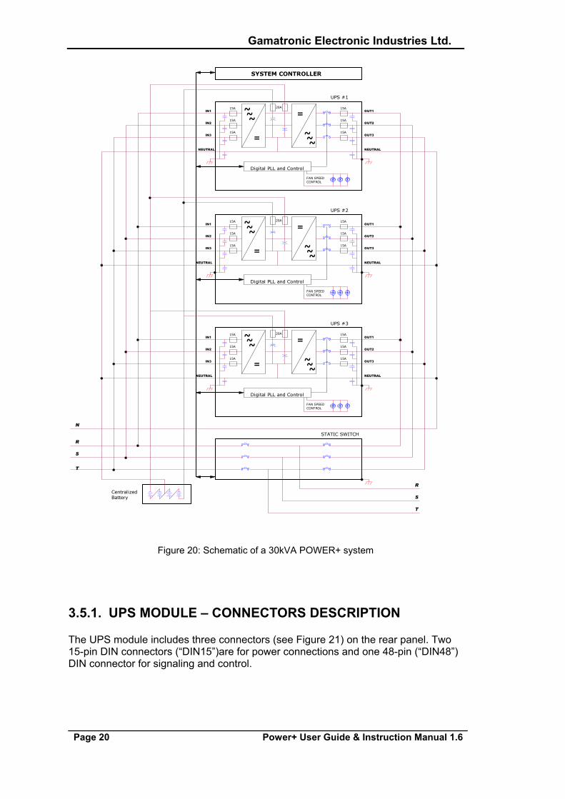
3.5. CABLING AND CONNECTIONS
The cabling and wiring of the 30kVA Power+ system are illustrated in Figure 20.
Gamatronic Electronic Industries Ltd.
Page 20 Power+ User Guide & Instruction Manual 1.6
20A
~
UPS #2
=
~~IN1 OUT1
IN2
IN3
OUT2
OUT3
=
~~~
NEUTRALNEUTRAL
+
+
FAN SPEEDCONTROL
Digital PLL and Control
15A15A
15A
15A
15A
15A
20A
UPS #3
=
~~IN1 ~ OUT1
IN2
IN3
OUT2
OUT3
=
~~
~
NEUTRAL NEUTRAL
+
+
FAN SPEEDCONTROL
Digital PLL and Control
15A
15A
15A
15A
15A
15A 20A
S
R
T
T
S
R
SYSTEM CONTROLLER
N
CentralizedBattery
~
UPS #1
=
STATIC SWITCH
~ OUT1IN1 ~
IN2
IN3
OUT2
OUT3
=
~~
~
NEUTRAL NEUTRAL
+
+
FAN SPEEDCONTROL
Digital PLL and Control
15A15A
15A
15A
15A
15A
Figure 20: Schematic of a 30kVA POWER+ system
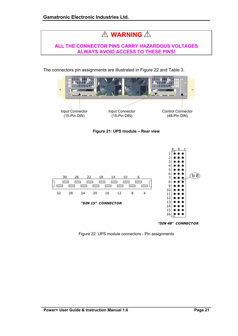
3.5.1. UPS MODULE – CONNECTORS DESCRIPTION
The UPS module includes three connectors (see Figure 21) on the rear panel. Two 15-pin DIN connectors (“DIN15”)are for power connections and one 48-pin (“DIN48”) DIN connector for signaling and control.
Gamatronic Electronic Industries Ltd.
Power+ User Guide & Instruction Manual 1.6 Page 21
WARNING
ALL THE CONNECTOR PINS CARRY HAZARDOUS VOLTAGES ALWAYS AVOID ACCESS TO THESE PINS!
The connectors pin assignments are illustrated in Figure 22 and Table 3.
Input Connector(15-Pin DIN)
Control Connector(48-Pin DIN)
Input Connector(15-Pin DIN)
Figure 21: UPS module – Rear view
ba c1
32
54
76
98
1110
1312
1514
16
b 8
"DIN 15" CONNECTOR
"DIN 48" CONNECTOR
32
30
28
26 22
24
18
20
14
16
10
12
6
8 4
Figure 22: UPS module connectors - Pin assignments
Gamatronic Electronic Industries Ltd.
Page 22 Power+ User Guide & Instruction Manual 1.6
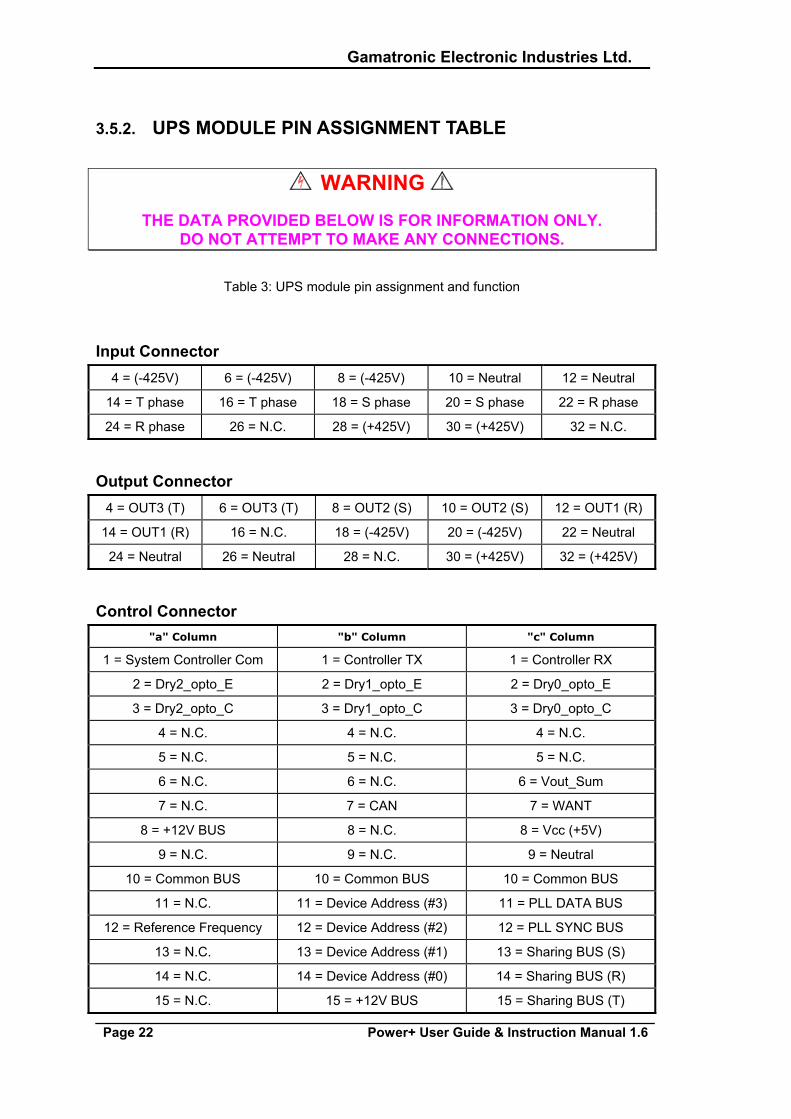
3.5.2. UPS MODULE PIN ASSIGNMENT TABLE
WARNING THE DATA PROVIDED BELOW IS FOR INFORMATION ONLY.
DO NOT ATTEMPT TO MAKE ANY CONNECTIONS.
Table 3: UPS module pin assignment and function
Input Connector 4 = (-425V) 6 = (-425V) 8 = (-425V) 10 = Neutral 12 = Neutral
14 = T phase 16 = T phase 18 = S phase 20 = S phase 22 = R phase
24 = R phase 26 = N.C. 28 = (+425V) 30 = (+425V) 32 = N.C.
Output Connector 4 = OUT3 (T) 6 = OUT3 (T) 8 = OUT2 (S) 10 = OUT2 (S) 12 = OUT1 (R)
14 = OUT1 (R) 16 = N.C. 18 = (-425V) 20 = (-425V) 22 = Neutral
24 = Neutral 26 = Neutral 28 = N.C. 30 = (+425V) 32 = (+425V)
Control Connector "a" Column "b" Column "c" Column
1 = System Controller Com 1 = Controller TX 1 = Controller RX
2 = Dry2_opto_E 2 = Dry1_opto_E 2 = Dry0_opto_E
3 = Dry2_opto_C 3 = Dry1_opto_C 3 = Dry0_opto_C
4 = N.C. 4 = N.C. 4 = N.C.
5 = N.C. 5 = N.C. 5 = N.C.
6 = N.C. 6 = N.C. 6 = Vout_Sum
7 = N.C. 7 = CAN 7 = WANT
8 = +12V BUS 8 = N.C. 8 = Vcc (+5V)
9 = N.C. 9 = N.C. 9 = Neutral
10 = Common BUS 10 = Common BUS 10 = Common BUS
11 = N.C. 11 = Device Address (#3) 11 = PLL DATA BUS
12 = Reference Frequency 12 = Device Address (#2) 12 = PLL SYNC BUS
13 = N.C. 13 = Device Address (#1) 13 = Sharing BUS (S)
14 = N.C. 14 = Device Address (#0) 14 = Sharing BUS (R)
15 = N.C. 15 = +12V BUS 15 = Sharing BUS (T)
Gamatronic Electronic Industries Ltd.
Power+ User Guide & Instruction Manual 1.6 Page 23
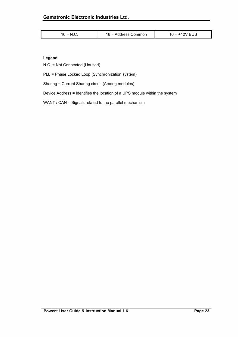
16 = N.C. 16 = Address Common 16 = +12V BUS
Legend
N.C. = Not Connected (Unused)
PLL = Phase Locked Loop (Synchronization system)
Sharing = Current Sharing circuit (Among modules)
Device Address = Identifies the location of a UPS module within the system
WANT / CAN = Signals related to the parallel mechanism
Gamatronic Electronic Industries Ltd.
Page 24 Power+ User Guide & Instruction Manual 1.6
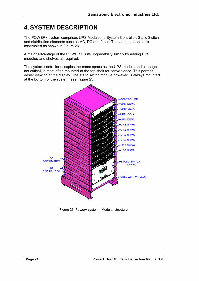
4. SYSTEM DESCRIPTION The POWER+ system comprises UPS Modules, a System Controller, Static Switch and distribution elements such as AC, DC and fuses. These components are assembled as shown in Figure 23.
A major advantage of the POWER+ is its upgradability simply by adding UPS modules and shelves as required.
The system controller occupies the same space as the UPS module and although not critical, is most often mounted at the top shelf for convenience. This permits easier viewing of the display. The static switch module however, is always mounted at the bottom of the system (see Figure 23).
Figure 23: Power+ system - Modular structure
Gamatronic Electronic Industries Ltd.
Power+ User Guide & Instruction Manual 1.6 Page 25
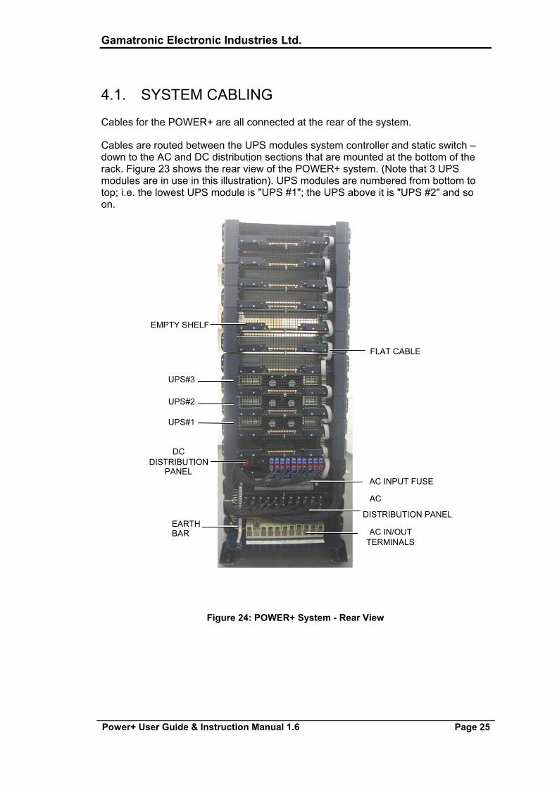
4.1. SYSTEM CABLING
Cables for the POWER+ are all connected at the rear of the system.
Cables are routed between the UPS modules system controller and static switch – down to the AC and DC distribution sections that are mounted at the bottom of the rack. Figure 23 shows the rear view of the POWER+ system. (Note that 3 UPS modules are in use in this illustration). UPS modules are numbered from bottom to top; i.e. the lowest UPS module is "UPS #1"; the UPS above it is "UPS #2" and so on.
EMPTY SHELF
UPS#3
UPS#2
UPS#1
DC DISTRIBUTION
PANEL
EARTH BAR
FLAT CABLE
AC INPUT FUSE AC
DISTRIBUTION PANEL AC IN/OUT
TERMINALS
Figure 24: POWER+ System - Rear View
Gamatronic Electronic Industries Ltd.
Page 26 Power+ User Guide & Instruction Manual 1.6
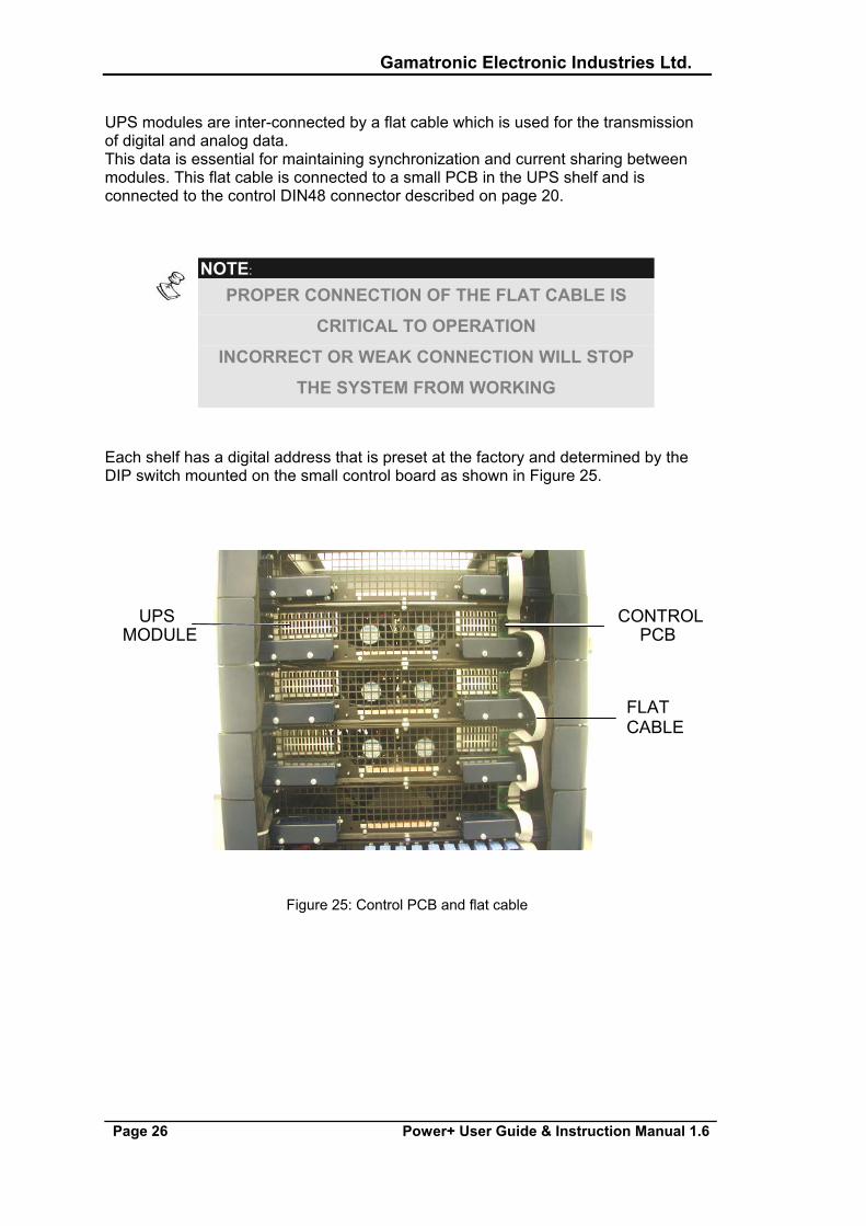
UPS modules are inter-connected by a flat cable which is used for the transmission of digital and analog data. This data is essential for maintaining synchronization and current sharing between modules. This flat cable is connected to a small PCB in the UPS shelf and is connected to the control DIN48 connector described on page 20.
NOTE:
PROPER CONNECTION OF THE FLAT CABLE IS
CRITICAL TO OPERATION
INCORRECT OR WEAK CONNECTION WILL STOP
THE SYSTEM FROM WORKING
Each shelf has a digital address that is preset at the factory and determined by the DIP switch mounted on the small control board as shown in Figure 25.
Figure 25: Control PCB and flat cable
UPS MODULE
CONTROL PCB
FLAT CABLE
Gamatronic Electronic Industries Ltd.
Power+ User Guide & Instruction Manual 1.6 Page 27
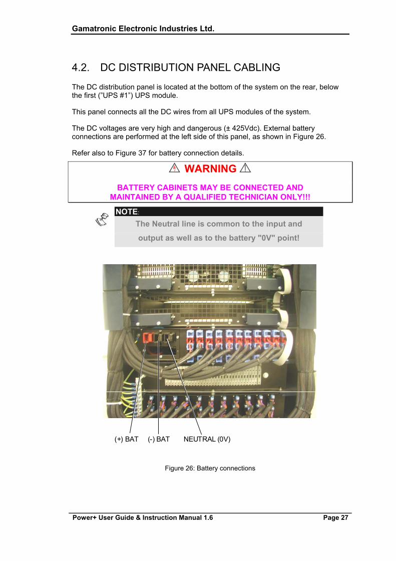
4.2. DC DISTRIBUTION PANEL CABLING
The DC distribution panel is located at the bottom of the system on the rear, below the first (”UPS #1”) UPS module.
This panel connects all the DC wires from all UPS modules of the system.
The DC voltages are very high and dangerous (± 425Vdc). External battery connections are performed at the left side of this panel, as shown in Figure 26.
Refer also to Figure 37 for battery connection details.
WARNING BATTERY CABINETS MAY BE CONNECTED AND
MAINTAINED BY A QUALIFIED TECHNICIAN ONLY!!!
NOTE:
The Neutral line is common to the input and
output as well as to the battery "0V" point!
Figure 26: Battery connections
(+) BAT (-) BAT NEUTRAL (0V)
Gamatronic Electronic Industries Ltd.
Page 28 Power+ User Guide & Instruction Manual 1.6
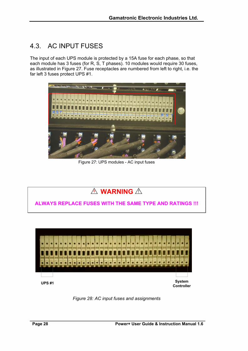
4.3. AC INPUT FUSES
The input of each UPS module is protected by a 15A fuse for each phase, so that each module has 3 fuses (for R, S, T phases). 10 modules would require 30 fuses, as illustrated in Figure 27. Fuse receptacles are numbered from left to right, i.e. the far left 3 fuses protect UPS #1.
Figure 27: UPS modules - AC input fuses
WARNING ALWAYS REPLACE FUSES WITH THE SAME TYPE AND RATINGS !!!
UPS #1 SystemController
Figure 28: AC input fuses and assignments
R S T ......... ......... .................. .......... .................. .......... .................. ......R S T
Gamatronic Electronic Industries Ltd.
Power+ User Guide & Instruction Manual 1.6 Page 29
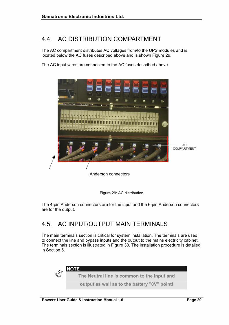
4.4. AC DISTRIBUTION COMPARTMENT
The AC compartment distributes AC voltages from/to the UPS modules and is located below the AC fuses described above and is shown Figure 29.
The AC input wires are connected to the AC fuses described above.
R S T
ACCOMPARTMENT
Figure 29: AC distribution
The 4-pin Anderson connectors are for the input and the 6-pin Anderson connectors are for the output.
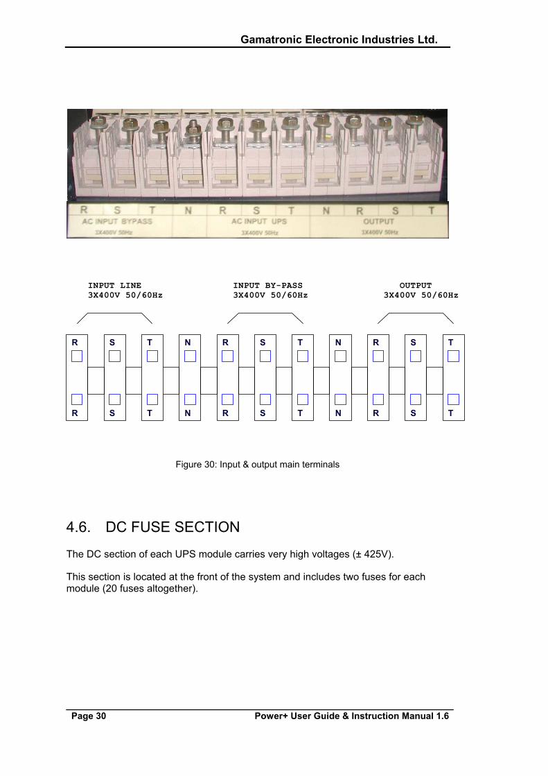
4.5. AC INPUT/OUTPUT MAIN TERMINALS
The main terminals section is critical for system installation. The terminals are used to connect the line and bypass inputs and the output to the mains electricity cabinet. The terminals section is illustrated in Figure 30. The installation procedure is detailed in Section 5.
NOTE:
The Neutral line is common to the input and
output as well as to the battery "0V" point!
Anderson connectors
Gamatronic Electronic Industries Ltd.
Page 30 Power+ User Guide & Instruction Manual 1.6
R S T R S TN R S TN
INPUT BY-PASS3X400V 50/60Hz
OUTPUT 3X400V 50/60Hz
INPUT LINE3X400V 50/60Hz
R S T R S TN R S TN
Figure 30: Input & output main terminals
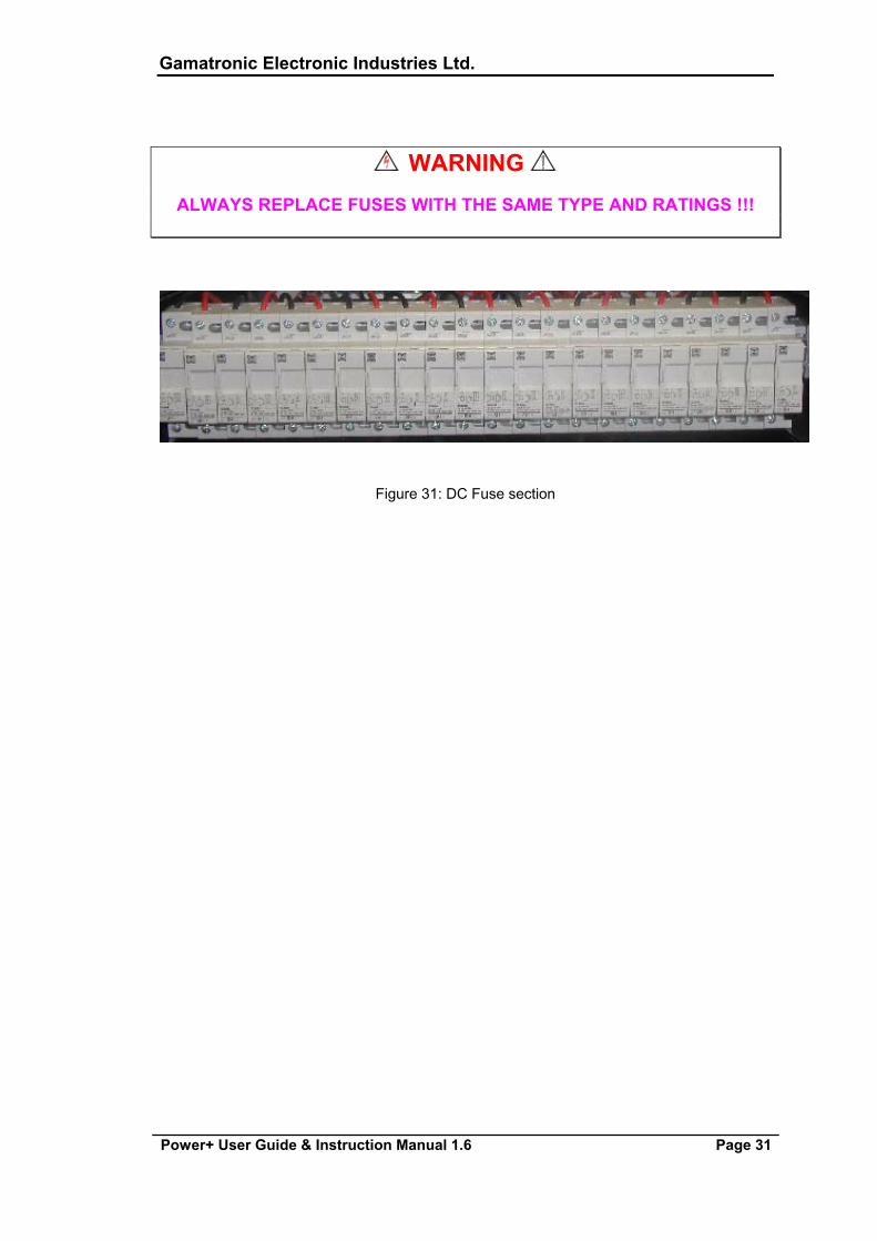
4.6. DC FUSE SECTION
The DC section of each UPS module carries very high voltages (± 425V).
This section is located at the front of the system and includes two fuses for each module (20 fuses altogether).
Gamatronic Electronic Industries Ltd.
Power+ User Guide & Instruction Manual 1.6 Page 31
WARNING ALWAYS REPLACE FUSES WITH THE SAME TYPE AND RATINGS !!!
Figure 31: DC Fuse section
Gamatronic Electronic Industries Ltd.
Page 32 Power+ User Guide & Instruction Manual 1.6
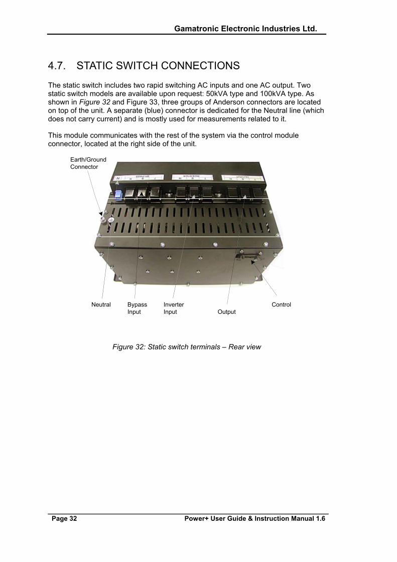
4.7. STATIC SWITCH CONNECTIONS
The static switch includes two rapid switching AC inputs and one AC output. Two static switch models are available upon request: 50kVA type and 100kVA type. As shown in Figure 32 and Figure 33, three groups of Anderson connectors are located on top of the unit. A separate (blue) connector is dedicated for the Neutral line (which does not carry current) and is mostly used for measurements related to it.
This module communicates with the rest of the system via the control module connector, located at the right side of the unit.
Earth/GroundConnector
Neutral Bypass Inverter ControlInput Input Output
Figure 32: Static switch terminals – Rear view
Gamatronic Electronic Industries Ltd.
Power+ User Guide & Instruction Manual 1.6 Page 33
UPSModules
DC FuseCover
StaticSwitch
EmergencyShutdownwith a protectivecover
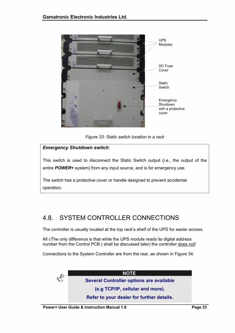
Figure 33: Static switch location in a rack
Emergency Shutdown switch:
This switch is used to disconnect the Static Switch output (i.e., the output of the
entire POWER+ system) from any input source, and is for emergency use.
The switch has a protective cover or handle designed to prevent accidental
operation.
4.8. SYSTEM CONTROLLER CONNECTIONS
The controller is usually located at the top rack’s shelf of the UPS for easier access.
All cThe only difference is that while the UPS module reads its digital address number from the Control PCB ( shall be discussed later) the controller does not!
Connections to the System Controller are from the rear, as shown in Figure 34.
NOTE:
Several Controller options are available
(e.g TCP/IP, cellular and more).
Refer to your dealer for further details.
Gamatronic Electronic Industries Ltd.
Page 34 Power+ User Guide & Instruction Manual 1.6
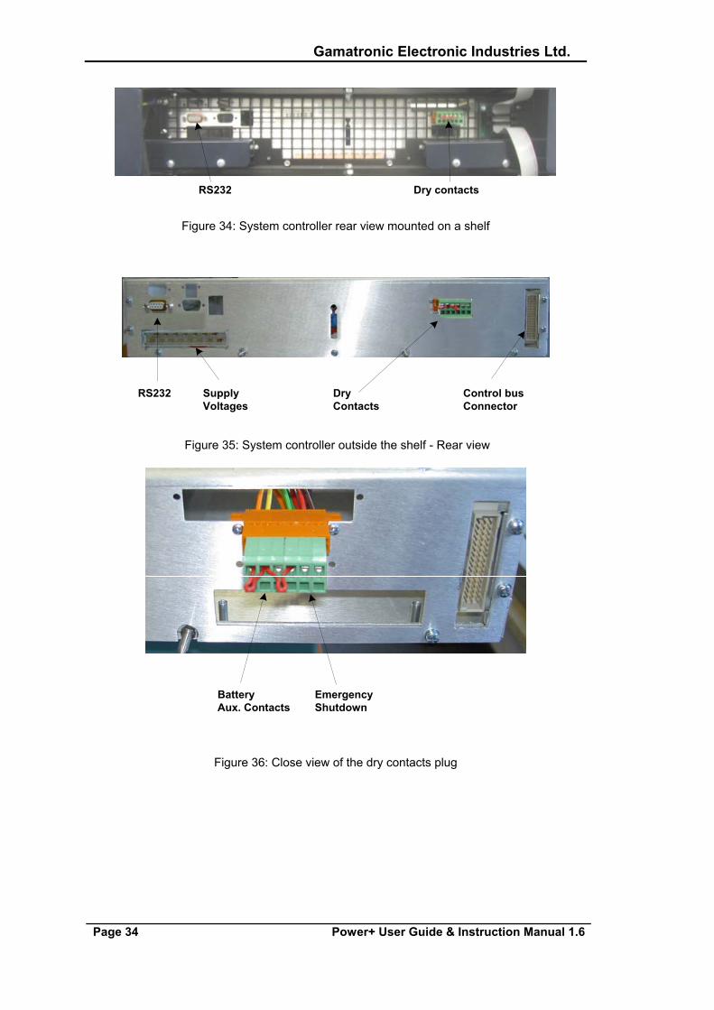
RS232 Dry contacts
Figure 34: System controller rear view mounted on a shelf
RS232 Supply Dry Control busVoltages Contacts Connector
Figure 35: System controller outside the shelf - Rear view
Battery EmergencyAux. Contacts Shutdown
Figure 36: Close view of the dry contacts plug
Gamatronic Electronic Industries Ltd.
Power+ User Guide & Instruction Manual 1.6 Page 35
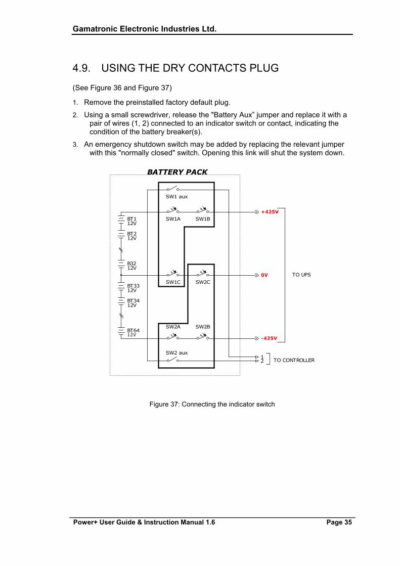
4.9. USING THE DRY CONTACTS PLUG
(See Figure 36 and Figure 37)
1. Remove the preinstalled factory default plug.
2. Using a small screwdriver, release the "Battery Aux” jumper and replace it with a pair of wires (1, 2) connected to an indicator switch or contact, indicating the condition of the battery breaker(s).
3. An emergency shutdown switch may be added by replacing the relevant jumper with this "normally closed" switch. Opening this link will shut the system down.
BT3312V
SW2C
-425V
B3212V
SW1A+425V
BT6412V
SW1 aux
TO CONTROLLER
TO UPS
2
0V
BATTERY PACK
1
SW1BBT112V
SW2 aux
BT212V
SW2A SW2B
BT3412V
SW1C
Figure 37: Connecting the indicator switch
Gamatronic Electronic Industries Ltd.
Page 36 Power+ User Guide & Instruction Manual 1.6
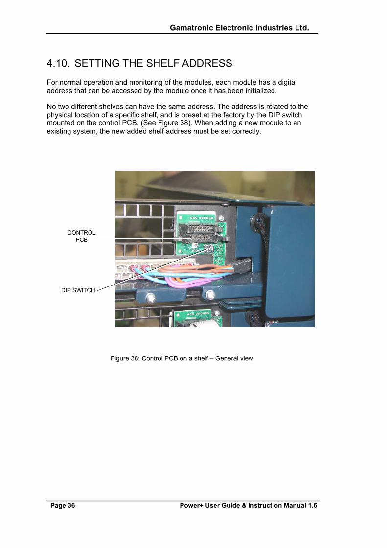
4.10. SETTING THE SHELF ADDRESS
For normal operation and monitoring of the modules, each module has a digital address that can be accessed by the module once it has been initialized.
No two different shelves can have the same address. The address is related to the physical location of a specific shelf, and is preset at the factory by the DIP switch mounted on the control PCB. (See Figure 38). When adding a new module to an existing system, the new added shelf address must be set correctly.
DIP SWITCH
CONTROLPCB
Figure 38: Control PCB on a shelf – General view

Gamatronic Electronic Industries Ltd.
Power+ User Guide & Instruction Manual 1.6 Page 37
Figure 39: DIP switch – Close-up
Figure 39 shows the control PCB DIP switch.
In the example shown the DIP switch is set as follows:
1= "on", 2= "on", 3= "on", 4="on”, indicating UPS #1. See Table 4 and FIGURE 40.
Gamatronic Electronic Industries Ltd.
Page 38 Power+ User Guide & Instruction Manual 1.6
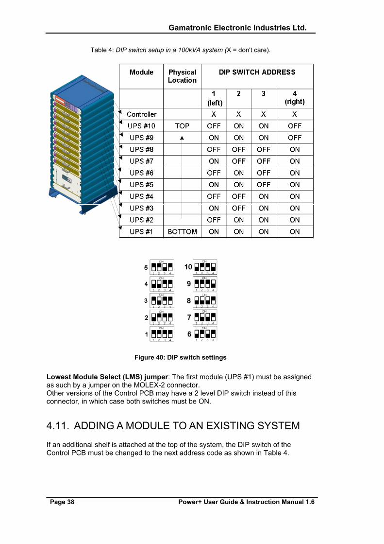
Table 4: DIP switch setup in a 100kVA system (X = don't care).
Figure 40: DIP switch settings
Lowest Module Select (LMS) jumper: The first module (UPS #1) must be assigned as such by a jumper on the MOLEX-2 connector. Other versions of the Control PCB may have a 2 level DIP switch instead of this connector, in which case both switches must be ON.
4.11. ADDING A MODULE TO AN EXISTING SYSTEM
If an additional shelf is attached at the top of the system, the DIP switch of the Control PCB must be changed to the next address code as shown in Table 4.
Gamatronic Electronic Industries Ltd.
Power+ User Guide & Instruction Manual 1.6 Page 39
5. SYSTEM INSTALLATION
WARNING
RISK OF ELECTRICAL SHOCK OR INJURY!
INSTALLATION MAY BE PERFORMED BY QUALIFIED TECHNICIAN ONLY!
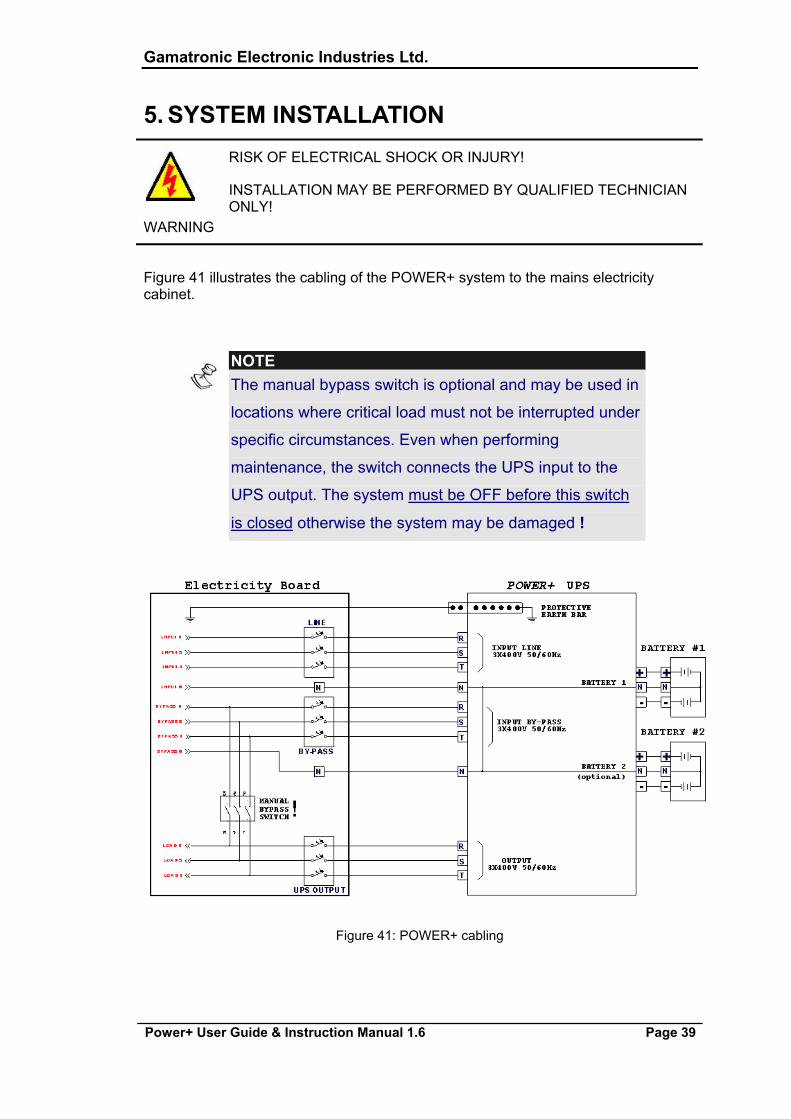
Figure 41 illustrates the cabling of the POWER+ system to the mains electricity cabinet.
NOTE: The manual bypass switch is optional and may be used in
locations where critical load must not be interrupted under
specific circumstances. Even when performing
maintenance, the switch connects the UPS input to the
UPS output. The system must be OFF before this switch
is closed otherwise the system may be damaged !
Figure 41: POWER+ cabling
Gamatronic Electronic Industries Ltd.
Page 40 Power+ User Guide & Instruction Manual 1.6
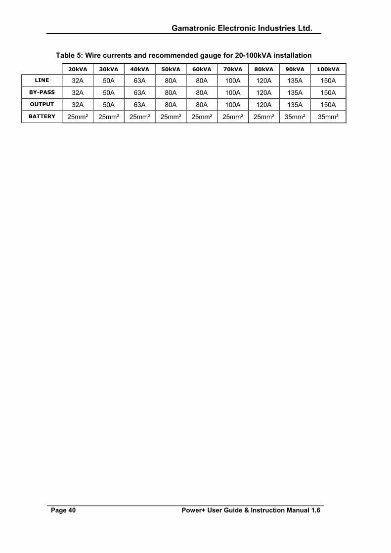
Table 5: Wire currents and recommended gauge for 20-100kVA installation
20kVA 30kVA 40kVA 50kVA 60kVA 70kVA 80kVA 90kVA 100kVA
LINE 32A 50A 63A 80A 80A 100A 120A 135A 150A
BY-PASS 32A 50A 63A 80A 80A 100A 120A 135A 150A
OUTPUT 32A 50A 63A 80A 80A 100A 120A 135A 150A
BATTERY 25mm² 25mm² 25mm² 25mm² 25mm² 25mm² 25mm² 35mm² 35mm²
Gamatronic Electronic Industries Ltd.
Power+ User Guide & Instruction Manual 1.6 Page 41
5.1. INSTALLATION AND START-UP SEQUENCE 1. Prepare the proper infrastructure for the system with adequate cables and
connections.
2. Prepare the POWER+ for installation. Ensure all components and modules are complete and mechanically fastened to their shelves.
3. Verify that all energy sources are disconnected, all switches are OFF.
4. Connect the system to the mains electricity cabinet.
5. Connect the battery set(s) to the system.
6. Re-check your connections.
7. Ensure that the manual bypass switch (if any) is OFF.
8. Turn on the AC switches and wait for the system to initialize (about 2 minutes).
9. Ensure all LEDs are green and all indications are normal.
10. Switch on all battery switches on all battery boxes.
11. Switch on loads.
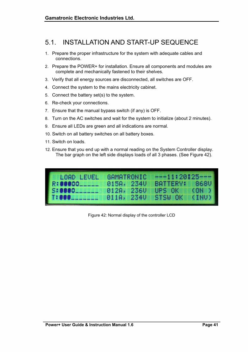
12. Ensure that you end up with a normal reading on the System Controller display. The bar graph on the left side displays loads of all 3 phases. (See Figure 42).
Figure 42: Normal display of the controller LCD

Gamatronic Electronic Industries Ltd.
Page 42 Power+ User Guide & Instruction Manual 1.6
5.2. USING THE SYSTEM CONTROLLER
Some of the most common displays are briefly described below.
In order to extract more information proceed as follows.
Pressing the "ENTER" button will display a menu:
Figure 43: Controller menu #1
SYSTEM General information such as voltages, currents etc.
UPS Information for a specific UPS module
SELFTEST Self checking of the Controller's components (supply, RTC, memory)
HISTORY History log events (last 255 events, dated and timed)
BATTERY Charging / discharging voltages and currents, battery test etc.
ALARM Detailed alarm status
SETUP Configuring the system (number of modules, alarm, time etc.)
STATIC SW Static Switch data
COMM Determining the type of communication (TCP/IP, RS232 or WING)
The SYSTEM menu will show the DC voltages (positive, negative and summary):
Figure 44: System DC voltages
1. Scroll down to view the three-phase input and output total voltage and current:
Gamatronic Electronic Industries Ltd.
Power+ User Guide & Instruction Manual 1.6 Page 43
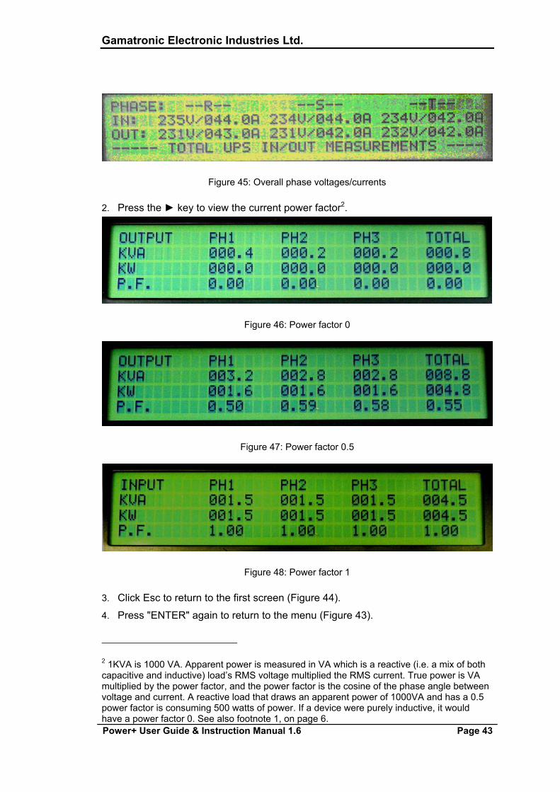
Figure 45: Overall phase voltages/currents
2. Press the ► key to view the current power factor2.
Figure 46: Power factor 0
Figure 47: Power factor 0.5
Figure 48: Power factor 1
3. Click Esc to return to the first screen (Figure 44).
4. Press "ENTER" again to return to the menu (Figure 43).
2 1KVA is 1000 VA. Apparent power is measured in VA which is a reactive (i.e. a mix of both capacitive and inductive) load’s RMS voltage multiplied the RMS current. True power is VA multiplied by the power factor, and the power factor is the cosine of the phase angle between voltage and current. A reactive load that draws an apparent power of 1000VA and has a 0.5 power factor is consuming 500 watts of power. If a device were purely inductive, it would have a power factor 0. See also footnote 1, on page 6.
Gamatronic Electronic Industries Ltd.
Page 44 Power+ User Guide & Instruction Manual 1.6
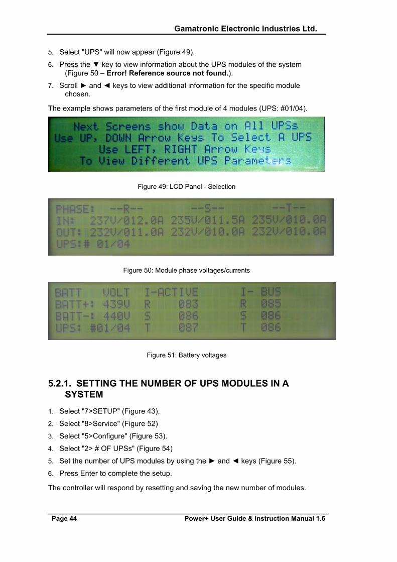
5. Select "UPS" will now appear (Figure 49).
6. Press the ▼ key to view information about the UPS modules of the system (Figure 50 – Error! Reference source not found.).
7. Scroll ► and ◄ keys to view additional information for the specific module chosen.
The example shows parameters of the first module of 4 modules (UPS: #01/04).
Figure 49: LCD Panel - Selection
Figure 50: Module phase voltages/currents
Figure 51: Battery voltages
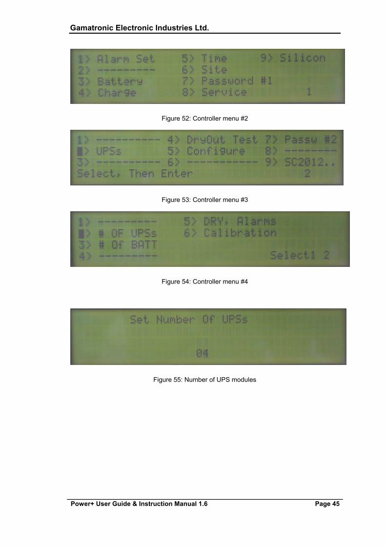
5.2.1. SETTING THE NUMBER OF UPS MODULES IN A SYSTEM
1. Select "7>SETUP" (Figure 43),
2. Select "8>Service" (Figure 52)
3. Select "5>Configure" (Figure 53).
4. Select "2> # OF UPSs" (Figure 54)
5. Set the number of UPS modules by using the ► and ◄ keys (Figure 55).
6. Press Enter to complete the setup.
The controller will respond by resetting and saving the new number of modules.
Gamatronic Electronic Industries Ltd.
Power+ User Guide & Instruction Manual 1.6 Page 45
Figure 52: Controller menu #2
Figure 53: Controller menu #3
Figure 54: Controller menu #4
Figure 55: Number of UPS modules
Gamatronic Electronic Industries Ltd.
Page 46 Power+ User Guide & Instruction Manual 1.6
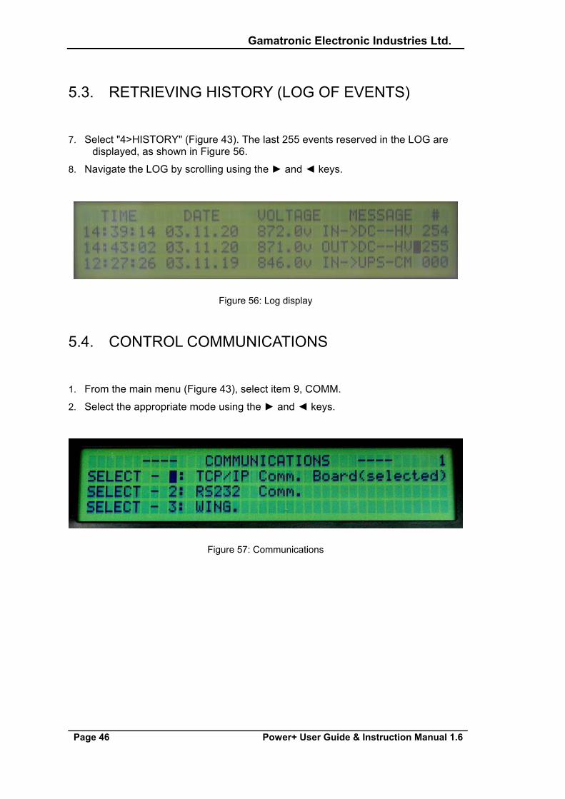
5.3. RETRIEVING HISTORY (LOG OF EVENTS)
7. Select "4>HISTORY" (Figure 43). The last 255 events reserved in the LOG are displayed, as shown in Figure 56.
8. Navigate the LOG by scrolling using the ► and ◄ keys.
Figure 56: Log display
5.4. CONTROL COMMUNICATIONS
1. From the main menu (Figure 43), select item 9, COMM.
2. Select the appropriate mode using the ► and ◄ keys.
Figure 57: Communications
Gamatronic Electronic Industries Ltd.
Power+ User Guide & Instruction Manual 1.6 Page 47
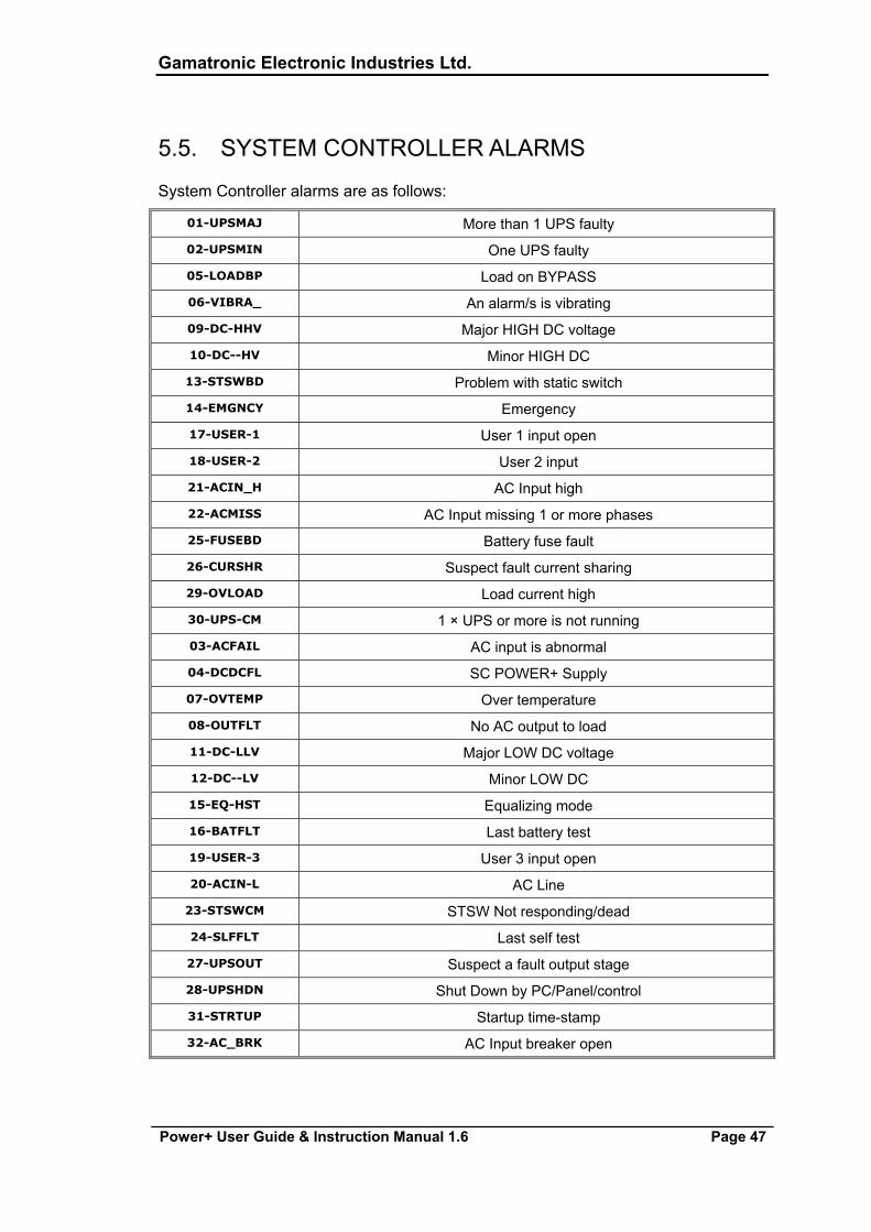
5.5. SYSTEM CONTROLLER ALARMS
System Controller alarms are as follows:
01-UPSMAJ More than 1 UPS faulty
02-UPSMIN One UPS faulty
05-LOADBP Load on BYPASS
06-VIBRA_ An alarm/s is vibrating
09-DC-HHV Major HIGH DC voltage
10-DC--HV Minor HIGH DC
13-STSWBD Problem with static switch
14-EMGNCY Emergency
17-USER-1 User 1 input open
18-USER-2 User 2 input
21-ACIN_H AC Input high
22-ACMISS AC Input missing 1 or more phases
25-FUSEBD Battery fuse fault
26-CURSHR Suspect fault current sharing
29-OVLOAD Load current high
30-UPS-CM 1 × UPS or more is not running
03-ACFAIL AC input is abnormal
04-DCDCFL SC POWER+ Supply
07-OVTEMP Over temperature
08-OUTFLT No AC output to load
11-DC-LLV Major LOW DC voltage
12-DC--LV Minor LOW DC
15-EQ-HST Equalizing mode
16-BATFLT Last battery test
19-USER-3 User 3 input open
20-ACIN-L AC Line
23-STSWCM STSW Not responding/dead
24-SLFFLT Last self test
27-UPSOUT Suspect a fault output stage
28-UPSHDN Shut Down by PC/Panel/control
31-STRTUP Startup time-stamp
32-AC_BRK AC Input breaker open
Gamatronic Electronic Industries Ltd.
Page 48 Power+ User Guide & Instruction Manual 1.6
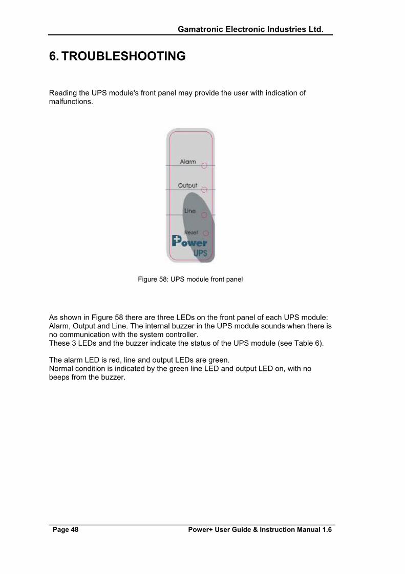
6. TROUBLESHOOTING
Reading the UPS module's front panel may provide the user with indication of malfunctions.
Figure 58: UPS module front panel
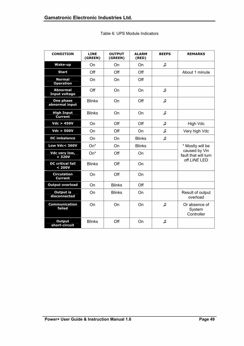
As shown in Figure 58 there are three LEDs on the front panel of each UPS module: Alarm, Output and Line. The internal buzzer in the UPS module sounds when there is no communication with the system controller. These 3 LEDs and the buzzer indicate the status of the UPS module (see Table 6).
The alarm LED is red, line and output LEDs are green. Normal condition is indicated by the green line LED and output LED on, with no beeps from the buzzer.
Gamatronic Electronic Industries Ltd.
Power+ User Guide & Instruction Manual 1.6 Page 49
Table 6: UPS Module Indicators
CONDITION LINE (GREEN)
OUTPUT (GREEN)
ALARM (RED)
BEEPS REMARKS
Wake-up On On On ♫
Start Off Off Off About 1 minute
Normal Operation
On On Off
Abnormal Input voltage
Off On On ♫
One phase abnormal input
Blinks On Off ♫
High Input Current
Blinks On On ♫
Vdc > 450V On Off Off ♫ High Vdc
Vdc > 500V On Off On ♫ Very high Vdc
DC imbalance On On Blinks ♫
Low Vdc< 360V On* On Blinks
Vdc very low, < 320V
On* Off On
DC critical fail < 200V
Blinks Off On
* Mostly will be caused by Vin
fault that will turn off LINE LED
Circulation Current
On Off On
Output overload On Blinks Off
Output is disconnected
On Blinks On Result of output overload
Communication failed
On On On ♫ Or absence of System
Controller
Output short-circuit
Blinks Off On ♫
Gamatronic Electronic Industries Ltd.
Page 50 Power+ User Guide & Instruction Manual 1.6
7. SYSTEM CONTROLLER AND COMMUNICATIONS
7.1. INTRODUCTION
The SCC POWER+ controller enables you to control and monitor all the individual components of the POWER+ system. Flexibility in setting the various configurations allows you to adjust the system to suit specific individual needs.
The system is equipped with clear, simple, user-friendly menus and submenus for easy monitoring, parameter definition and control of the system. The SCC provides communication with a wide range of management equipment, such as computers and mobile phones.
7.2. SCC POWER+ CHARACTERISTICS
The controller’s main functions include:
» Real-time 32 alarm display
» Manual and periodic battery testing
» An event log that records recent 254 events
» Service utility software
» Remote control of the system (TCP/IP, SNMP, PPP, GSM, GPRS, SMS,CDMA). See Chapter 12, page 65.
» Three levels of access to the controller: factory, supervisor and service
» Easy restoration of factory defaults
» Easy setting and saving of user defaults
» Flexible output dry contacts
» Manual bypass command
» System turn off with or without bypass
Gamatronic Electronic Industries Ltd.
Power+ User Guide & Instruction Manual 1.6 Page 51
7.3. CONTROLLER USER INTERFACE
The controller’s user interface includes:
» 40 × 4 LCD panel
» 6 Navigation Keys
» 3 Quiqe Command Buttons
» 8 Indication LEDs
» 2 Communication LEDs
7.4. SERVICE UTILITIES
There are several service programs intended for higher-level users (i.e. technicians, maintenance staff, etc.).
These programs allow canceling and performance of low-level operations in the system at the same time. These operations are very complex and should be performed by authorized personnel only.
These programs allow the operator to:
» Change configuration
» Manually turn off and on UPS
» Test dry contact outputs
» Switch to alternative version of the software
» Change communication settings
» Restart the controller
» Restart the network adapter
7.4.1. START-UP SCREENS
The welcome screen is displayed for a few seconds when the controller is switched on or restarted, and is immediately followed by a self-check test.
On completion of the self-check test the initializing screen appears and remains on display until the controller’s restarting process is completed. The software’s version is shown on the second row. The time remaining in the restart process appears on the fourth row of the screen. The main screen appears once the initializing screen closed.
The main screen provides the basic and essential information about the real-time status of the power system. The LED indicator lights located to the right of the screen, warn if there is a problem. The main menu remains displayed until one of the
Gamatronic Electronic Industries Ltd.
Page 52 Power+ User Guide & Instruction Manual 1.6
keys is pressed. The controller automatically returns to this main menu screen whenever a key is not pressed for five minutes.
The following information is displayed on this screen:
» DATE - Current date
» TIME - Current time
» AC-VOLT - System input voltage from mains
» AC-CURRENT - System input current from mains
» AC-Output Voltage – System output voltage
» FL - Number of the active flash
» PD - Peripheral device status
» UP – UPS general status
From the main screen you can navigate to:
» The Fast Information Menu through which you can access the 7 Fast Information screens
» The Main Menu from which you can access:
» Monitor Screens that let you monitor the system and components
» Calibration Screens that let you calibrate the system and components
» Control Screens that let you control the system and components Fast Information Screens
In addition to the many screens displaying detailed information about all aspects of the system, there are seven Fast Information screens that contain further details about the real-time status of the system. These screens can be accessed from the Fast Information Menu.
Network Fast Information Screen
This screen provides information about network related parameters such as the IP address, the gateway address and the mask.
There is also a counter that shows the number of times the controller failed to connect with the server. The maximum value that the counter can display is 225. Under normal operating conditions the value should be 0.
There is also a count of the number of times there was no SNMP link. This value resets the Network card.
Dry Contact Fast Information Screen
This screen provides real-time data on the status of the input and output dry contacts.
Gamatronic Electronic Industries Ltd.
Power+ User Guide & Instruction Manual 1.6 Page 53
For both input and output dry contacts:
» A filled circle appears when the dry contact is closed.
» An unfilled circle appears when the dry contact is open.
System Alarm Status Fast Information Screen
This screen shows the status of the existing system faults, indicating whether or not they are active. This screen shows:
» A filled circle indicates an active fault.
» An empty circle indicates an inactive fault.
General Information Screen
The following table describes the information displayed on the Information screen:
FIELD DESCRIPTION
REV Software revision number
T.C. Temperature
V-SET Output voltage
MAINT Last maintenance date
V-AUX Input Voltage
SITE ID number of the site
BATT General battery information
Gamatronic Electronic Industries Ltd.
Page 54 Power+ User Guide & Instruction Manual 1.6
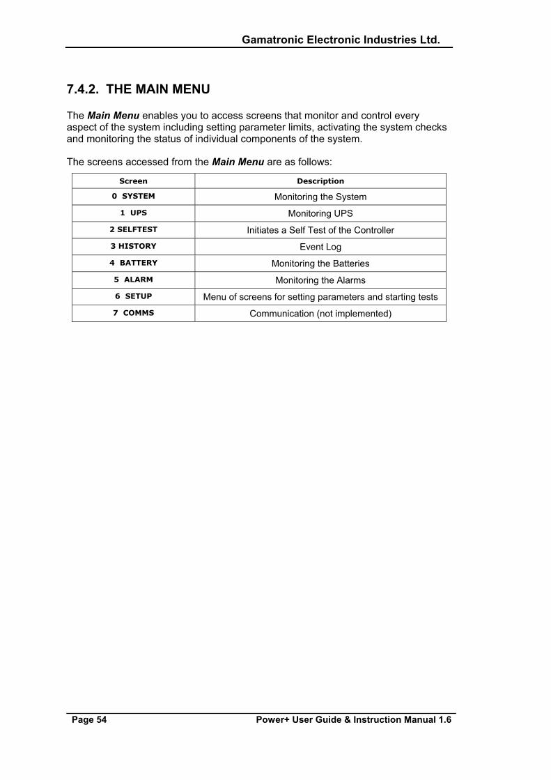
7.4.2. THE MAIN MENU
The Main Menu enables you to access screens that monitor and control every aspect of the system including setting parameter limits, activating the system checks and monitoring the status of individual components of the system.
The screens accessed from the Main Menu are as follows:
Screen Description
0 SYSTEM Monitoring the System
1 UPS Monitoring UPS
2 SELFTEST Initiates a Self Test of the Controller
3 HISTORY Event Log
4 BATTERY Monitoring the Batteries
5 ALARM Monitoring the Alarms
6 SETUP Menu of screens for setting parameters and starting tests
7 COMMS Communication (not implemented)
Gamatronic Electronic Industries Ltd.
Power+ User Guide & Instruction Manual 1.6 Page 55
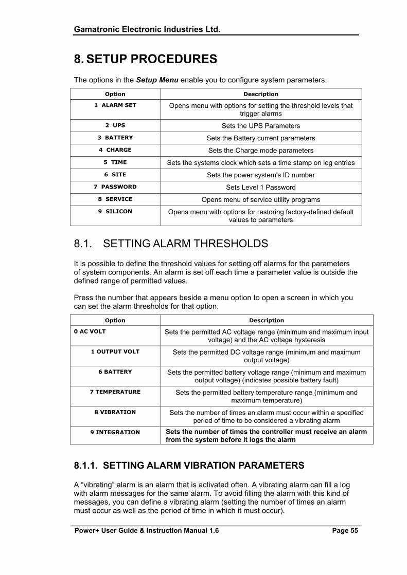
8. SETUP PROCEDURES The options in the Setup Menu enable you to configure system parameters.
Option Description
1 ALARM SET Opens menu with options for setting the threshold levels that trigger alarms
2 UPS Sets the UPS Parameters
3 BATTERY Sets the Battery current parameters
4 CHARGE Sets the Charge mode parameters
5 TIME Sets the systems clock which sets a time stamp on log entries
6 SITE Sets the power system's ID number
7 PASSWORD Sets Level 1 Password
8 SERVICE Opens menu of service utility programs
9 SILICON Opens menu with options for restoring factory-defined default values to parameters
8.1. SETTING ALARM THRESHOLDS
It is possible to define the threshold values for setting off alarms for the parameters of system components. An alarm is set off each time a parameter value is outside the defined range of permitted values.
Press the number that appears beside a menu option to open a screen in which you can set the alarm thresholds for that option.
Option Description
0 AC VOLT Sets the permitted AC voltage range (minimum and maximum input voltage) and the AC voltage hysteresis
1 OUTPUT VOLT Sets the permitted DC voltage range (minimum and maximum output voltage)
6 BATTERY Sets the permitted battery voltage range (minimum and maximum output voltage) (indicates possible battery fault)
7 TEMPERATURE Sets the permitted battery temperature range (minimum and maximum temperature)
8 VIBRATION Sets the number of times an alarm must occur within a specified period of time to be considered a vibrating alarm
9 INTEGRATION Sets the number of times the controller must receive an alarm from the system before it logs the alarm
8.1.1. SETTING ALARM VIBRATION PARAMETERS
A “vibrating” alarm is an alarm that is activated often. A vibrating alarm can fill a log with alarm messages for the same alarm. To avoid filling the alarm with this kind of messages, you can define a vibrating alarm (setting the number of times an alarm must occur as well as the period of time in which it must occur).
Gamatronic Electronic Industries Ltd.
Page 56 Power+ User Guide & Instruction Manual 1.6
8.1.2. SETTING THE INTEGRATION FACTOR FOR ALARMS
The integration factor is the coefficient that determines the number of times an alarm must occur before the controller records it. The smaller the value of the coefficient is, the sooner the warning notification is received. However, with a small coefficient there is a chance that an alarm may be given for a glitch rather than a fault. The larger the value of the coefficient is, the more notification is delayed and the greater the reliability.
8.1.3. 'AUTO' TEST BATTERIES
The 'Auto' test option checks the periodic/automatic testing of the batteries.
8.2. SETTING PASSWORD LEVEL 1
A level 1(supervisor) password allows you to monitor and control the system.
Gamatronic Electronic Industries Ltd.
Power+ User Guide & Instruction Manual 1.6 Page 57
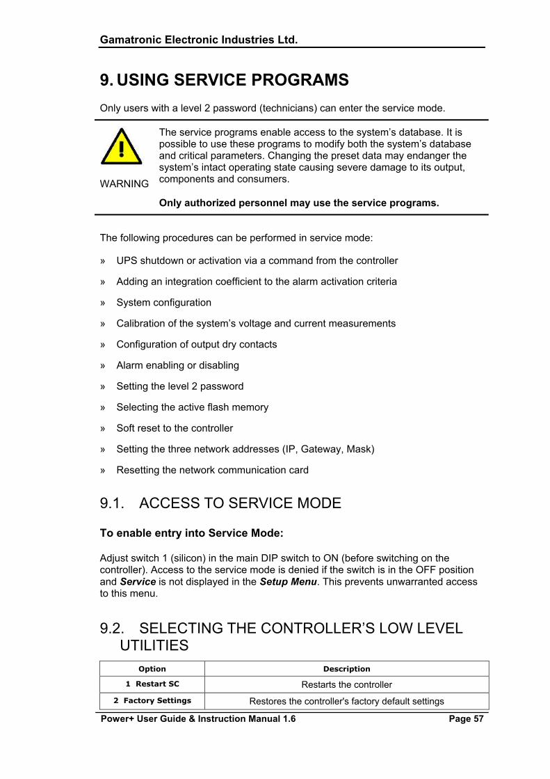
9. USING SERVICE PROGRAMS Only users with a level 2 password (technicians) can enter the service mode.
WARNING
The service programs enable access to the system’s database. It is possible to use these programs to modify both the system’s database and critical parameters. Changing the preset data may endanger the system’s intact operating state causing severe damage to its output, components and consumers. Only authorized personnel may use the service programs.
The following procedures can be performed in service mode:
» UPS shutdown or activation via a command from the controller
» Adding an integration coefficient to the alarm activation criteria
» System configuration
» Calibration of the system’s voltage and current measurements
» Configuration of output dry contacts
» Alarm enabling or disabling
» Setting the level 2 password
» Selecting the active flash memory
» Soft reset to the controller
» Setting the three network addresses (IP, Gateway, Mask)
» Resetting the network communication card
9.1. ACCESS TO SERVICE MODE
To enable entry into Service Mode:
Adjust switch 1 (silicon) in the main DIP switch to ON (before switching on the controller). Access to the service mode is denied if the switch is in the OFF position and Service is not displayed in the Setup Menu. This prevents unwarranted access to this menu.
9.2. SELECTING THE CONTROLLER’S LOW LEVEL UTILITIES
Option Description
1 Restart SC Restarts the controller
2 Factory Settings Restores the controller's factory default settings
Gamatronic Electronic Industries Ltd.
Page 58 Power+ User Guide & Instruction Manual 1.6
3 Network Sets the controller's network addresses
4 Reset MBX Resets the controllers' network card
5 MBX SW Upgrade Prevents the network card from resetting while the card is being upgraded
9.3. SETTING THE NETWORK ADDRESSES
9.3.1. SETTING THE SNMP FACTOR
The SNMP communication protocol communicates every few seconds with the controller to obtain updated data to send over the network. An SNMP failure to communicate indicates a possible need to reset the communications card. The SNMP factor sets the number of communication cycles that must pass without communication between the SNMP and the controller before the controller automatically resets the communication card.
9.4. CONFIGURING DRY CONTACTS AND ALARMS Option Description
1 Dry Contact Association Links alarms to dry contacts
2 LED Association Links LEDs to alarms
3 Severity Association Links severity levels to alarms
4 Enable/Disable Alarms Enables/Disables the alarms linked to the dry contacts
9.4.1. LINKING ALARMS TO DRY CONTACTS
The system has 6 dry contacts and 32 alarms. Any alarm can be linked to any dry contact. An alarm can be linked to more than one dry contact and a dry contact can be linked to more than one alarm.
9.4.2. LINKING ALARMS TO SEVERITY LEVELS
All system faults must have one of four possible severity levels:
» Warning
» Minor
» Major
» Critical
9.5. CALIBRATING MEASUREMENTS Option Description
1 AC-V Calib. Specifies actual AC voltage
Gamatronic Electronic Industries Ltd.
Power+ User Guide & Instruction Manual 1.6 Page 59
2 AC-I Calib. Specifies actual AC current for each phase
3 Batt. Volt Calib. Specifies the actual voltage of a battery
9.6. CONTROLLER SELF-TEST
This verifies that all the controller’s individual components including the controller’s main card and the internal voltage DC/DC supply unit are functioning correctly.
The self-test is performed either automatically at midnight or following controller activation. In addition, the self-test may also be performed at any time, as required, particularly if a malfunction is suspected.
9.7. BATTERY TEST
There are two types of battery tests: automatic and manual. It is possible to test both.
9.7.1. PERIODIC/AUTOMATIC BATTERY TEST
There is usually a waiting period of a number of days between the times that the system is programmed to perform an automatic or periodic battery test. An option therefore, is to simulate the passing of time so you can check at any time whether the periodic/automatic battery test occurs as configured.
Gamatronic Electronic Industries Ltd.
Page 60 Power+ User Guide & Instruction Manual 1.6
10. MONITORING THE SYSTEM The system is monitored by the controller and displays the following system information on LCD screens and menus.
» Power Meter
» System operating times
» System configuration
» Status of input dry contact
» Status of the UPSs
» Status of the batteries
» System temperature
» Communication status
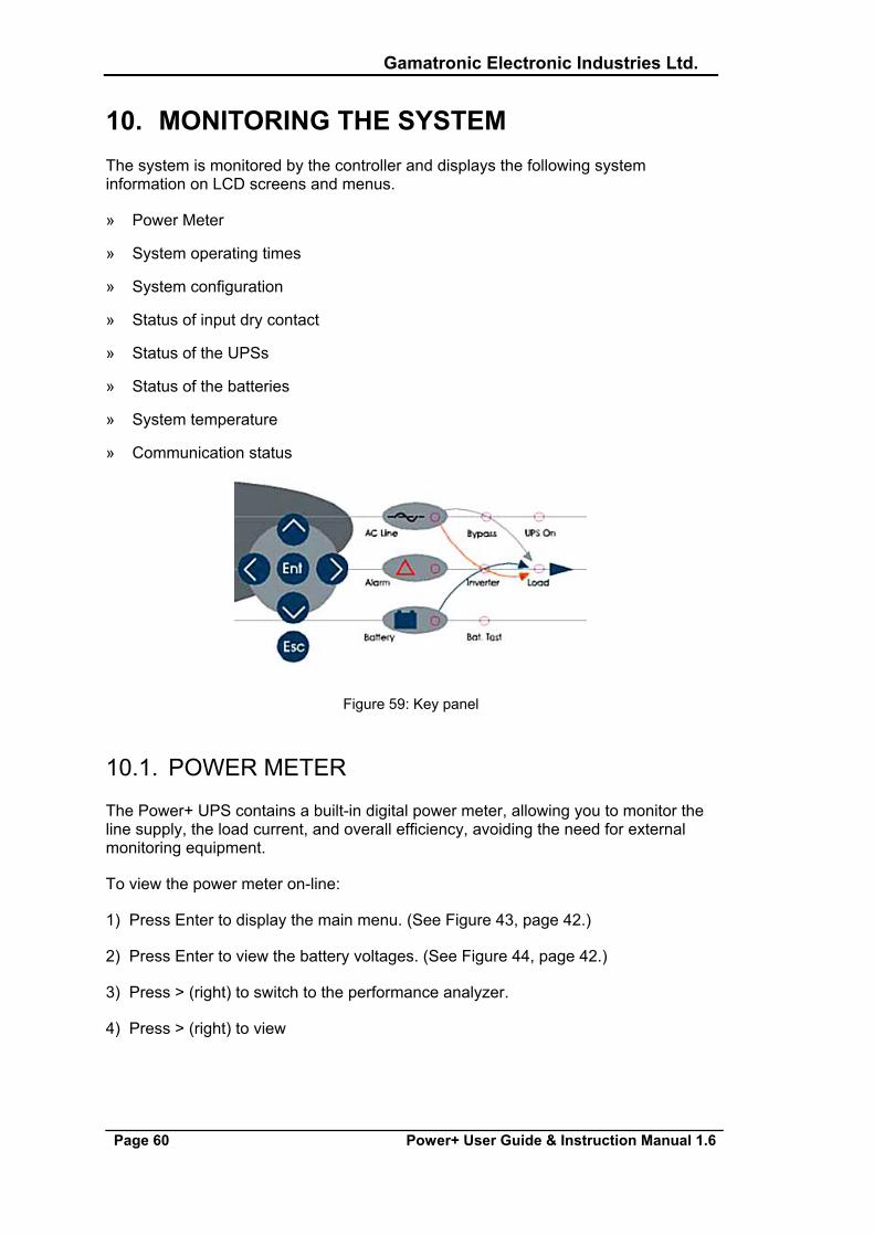
Figure 59: Key panel
10.1. POWER METER
The Power+ UPS contains a built-in digital power meter, allowing you to monitor the line supply, the load current, and overall efficiency, avoiding the need for external monitoring equipment.
To view the power meter on-line:
1) Press Enter to display the main menu. (See Figure 43, page 42.)
2) Press Enter to view the battery voltages. (See Figure 44, page 42.)
3) Press > (right) to switch to the performance analyzer.
4) Press > (right) to view
Gamatronic Electronic Industries Ltd.
Power+ User Guide & Instruction Manual 1.6 Page 61
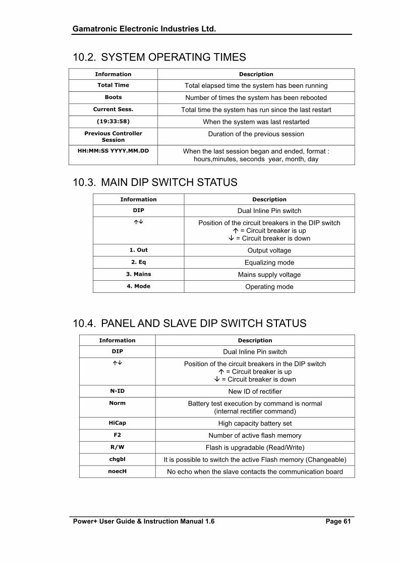
10.2. SYSTEM OPERATING TIMES Information Description
Total Time Total elapsed time the system has been running
Boots Number of times the system has been rebooted
Current Sess. Total time the system has run since the last restart
(19:33:58) When the system was last restarted
Previous Controller Session
Duration of the previous session
HH:MM:SS YYYY.MM.DD When the last session began and ended, format : hours,minutes, seconds year, month, day
10.3. MAIN DIP SWITCH STATUS Information Description
DIP Dual Inline Pin switch Position of the circuit breakers in the DIP switch
= Circuit breaker is up = Circuit breaker is down
1. Out Output voltage
2. Eq Equalizing mode
3. Mains Mains supply voltage
4. Mode Operating mode
10.4. PANEL AND SLAVE DIP SWITCH STATUS Information Description
DIP Dual Inline Pin switch Position of the circuit breakers in the DIP switch
= Circuit breaker is up = Circuit breaker is down
N-ID New ID of rectifier
Norm Battery test execution by command is normal (internal rectifier command)
HiCap High capacity battery set
F2 Number of active flash memory
R/W Flash is upgradable (Read/Write)
chgbl It is possible to switch the active Flash memory (Changeable)
noecH No echo when the slave contacts the communication board
Gamatronic Electronic Industries Ltd.
Page 62 Power+ User Guide & Instruction Manual 1.6
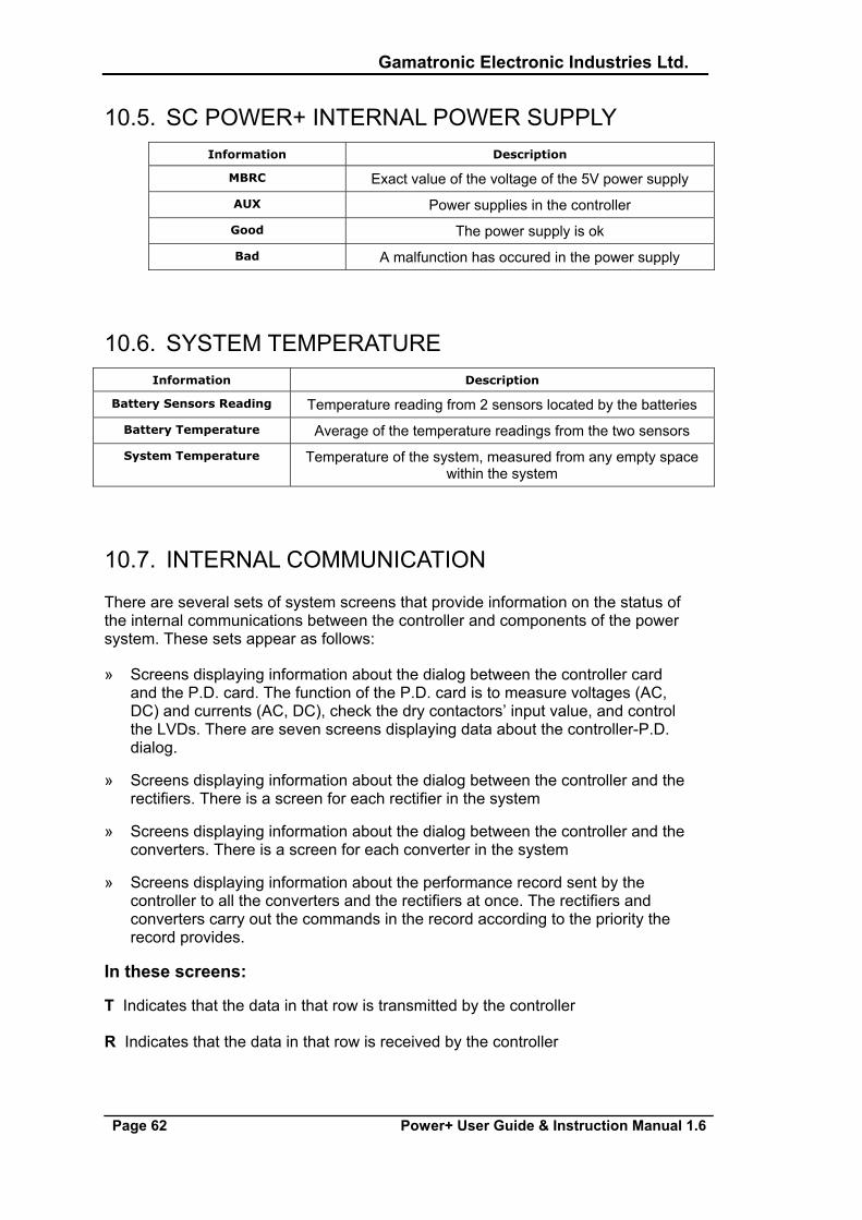
10.5. SC POWER+ INTERNAL POWER SUPPLY Information Description
MBRC Exact value of the voltage of the 5V power supply
AUX Power supplies in the controller
Good The power supply is ok
Bad A malfunction has occured in the power supply
10.6. SYSTEM TEMPERATURE Information Description
Battery Sensors Reading Temperature reading from 2 sensors located by the batteries
Battery Temperature Average of the temperature readings from the two sensors
System Temperature Temperature of the system, measured from any empty space within the system
10.7. INTERNAL COMMUNICATION
There are several sets of system screens that provide information on the status of the internal communications between the controller and components of the power system. These sets appear as follows:
» Screens displaying information about the dialog between the controller card and the P.D. card. The function of the P.D. card is to measure voltages (AC, DC) and currents (AC, DC), check the dry contactors’ input value, and control the LVDs. There are seven screens displaying data about the controller-P.D. dialog.
» Screens displaying information about the dialog between the controller and the rectifiers. There is a screen for each rectifier in the system
» Screens displaying information about the dialog between the controller and the converters. There is a screen for each converter in the system
» Screens displaying information about the performance record sent by the controller to all the converters and the rectifiers at once. The rectifiers and converters carry out the commands in the record according to the priority the record provides.
In these screens:
T Indicates that the data in that row is transmitted by the controller
R Indicates that the data in that row is received by the controller
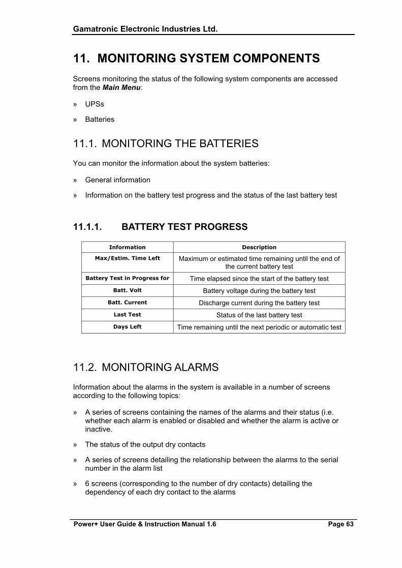
Gamatronic Electronic Industries Ltd.
Power+ User Guide & Instruction Manual 1.6 Page 63
11. MONITORING SYSTEM COMPONENTS Screens monitoring the status of the following system components are accessed from the Main Menu:
» UPSs
» Batteries
11.1. MONITORING THE BATTERIES
You can monitor the information about the system batteries:
» General information
» Information on the battery test progress and the status of the last battery test
11.1.1. BATTERY TEST PROGRESS
Information Description
Max/Estim. Time Left Maximum or estimated time remaining until the end of the current battery test
Battery Test in Progress for Time elapsed since the start of the battery test
Batt. Volt Battery voltage during the battery test
Batt. Current Discharge current during the battery test
Last Test Status of the last battery test
Days Left Time remaining until the next periodic or automatic test
11.2. MONITORING ALARMS
Information about the alarms in the system is available in a number of screens according to the following topics:
» A series of screens containing the names of the alarms and their status (i.e. whether each alarm is enabled or disabled and whether the alarm is active or inactive.
» The status of the output dry contacts
» A series of screens detailing the relationship between the alarms to the serial number in the alarm list
» 6 screens (corresponding to the number of dry contacts) detailing the dependency of each dry contact to the alarms
Gamatronic Electronic Industries Ltd.
Page 64 Power+ User Guide & Instruction Manual 1.6
» Six screens showing the relationship of the LED lights which can be user-programmed to the alarms
» 4 screens corresponding to the alarm severity definitions which may be programmed by you
» Use the Up and Down arrows to scroll through all the screens in a series.
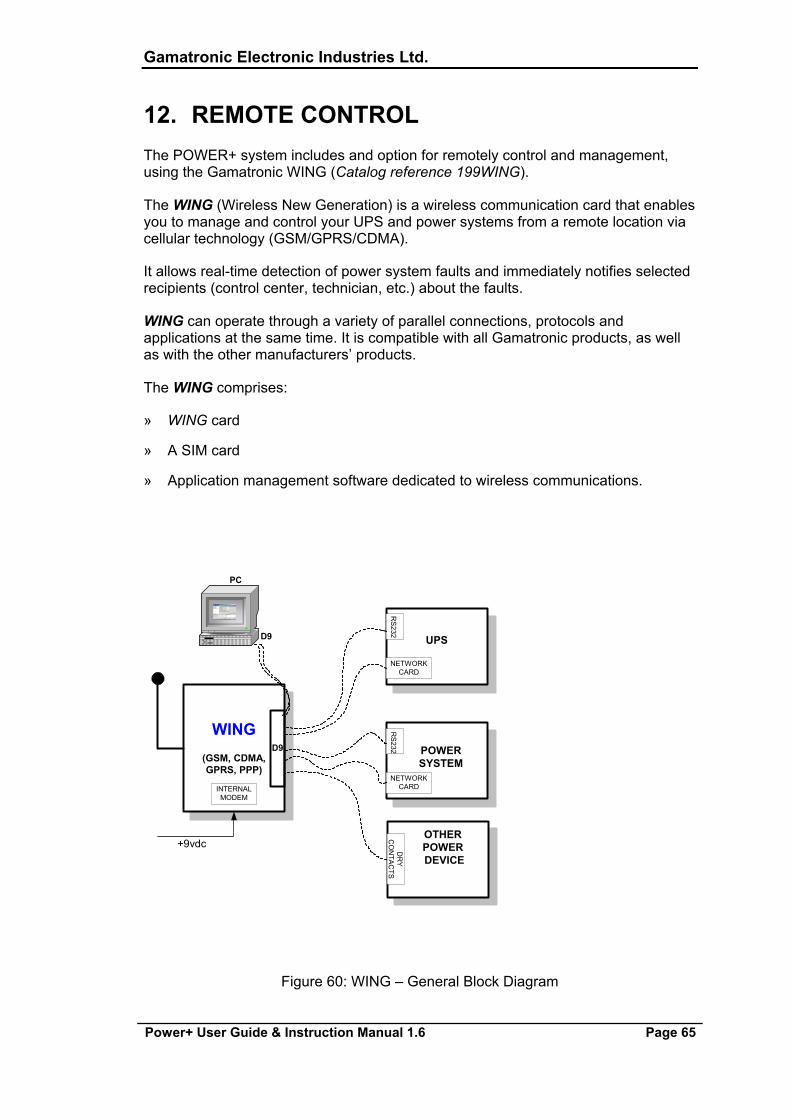
Gamatronic Electronic Industries Ltd.
Power+ User Guide & Instruction Manual 1.6 Page 65
12. REMOTE CONTROL The POWER+ system includes and option for remotely control and management, using the Gamatronic WING (Catalog reference 199WING).
The WING (Wireless New Generation) is a wireless communication card that enables you to manage and control your UPS and power systems from a remote location via cellular technology (GSM/GPRS/CDMA).
It allows real-time detection of power system faults and immediately notifies selected recipients (control center, technician, etc.) about the faults.
WING can operate through a variety of parallel connections, protocols and applications at the same time. It is compatible with all Gamatronic products, as well as with the other manufacturers’ products.
The WING comprises:
» WING card
» A SIM card
» Application management software dedicated to wireless communications.
WING(GSM, CDMA,GPRS, PPP)
D9
UPS
NETWORKCARD
NETWORKCARD
POWERSYSTEM
RS
232R
S232
INTERNALMODEM
+9vdc
PC
D9
OTHERPOWER DEVICE
DR
YC
ON
TAC
TS
Figure 60: WING – General Block Diagram
Gamatronic Electronic Industries Ltd.
Page 66 Power+ User Guide & Instruction Manual 1.6
The WING card contains an internal GSM/GPRS Modem plus antenna and a microprocessor that enables it to manage the power systems, monitor and control their values and status, and get real-time alarm notifications – all via any common cellular phone.
The user may communicate with the WING by either using a mobile phone or the dedicated GeMSi application provided by Gamatronic.
A service technician can perform the following activities using his mobile phone:
» Specify the code or command appropriate to the specific needs
» Send a message via SMS to the system ID
The system replies, informing the sender whether the command is accomplished or not. The card can filter the received messages according to authorizations (complete management/monitoring only/none).
The WING scans the remote power system every three seconds and alerts all the predefined recipients such as mobile phones, PCs, etc. (up to 10 recipients) whenever a malfunction occurs.
The WING enables you to protect your system by 2 levels of passwords (administrator, technician) and broadcast message in case of an alarm.
12.1. WING CONFIGURATIONS
The WING may be used in three types of configurations:
» PC & WING at the local end, and WING and power system at the remote location.
» PC & cellular modem at the local end, and WING and power system at the remote location.
» Cellular at the local end, and WING and power system at the remote location.
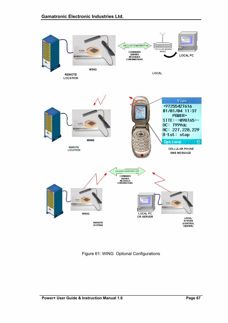
Gamatronic Electronic Industries Ltd.
Power+ User Guide & Instruction Manual 1.6 Page 67
Figure 61: WING Optional Configurations
Gamatronic Electronic Industries Ltd.
Page 68 Power+ User Guide & Instruction Manual 1.6
13. SC POWER+ NET LOGS The Event Log is a list of the last 256 events that occurred in the system and include:
» Details about when the event occurred and whether this refers to when the controller entered or exited the event
» Output voltage
» Status of dry contactors
» Type of event and its serial number
»
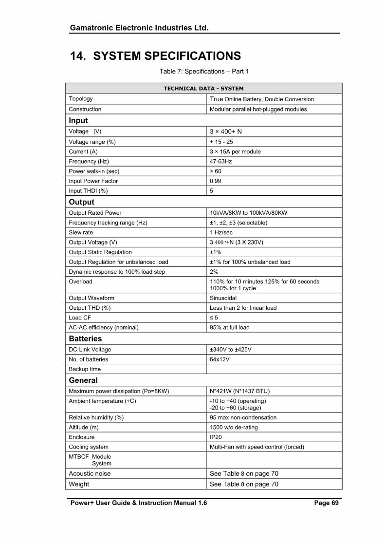
Gamatronic Electronic Industries Ltd.
Power+ User Guide & Instruction Manual 1.6 Page 69
14. SYSTEM SPECIFICATIONS Table 7: Specifications – Part 1
TECHNICAL DATA - SYSTEM
Topology True Online Battery, Double Conversion
Construction Modular parallel hot-plugged modules
Input Voltage (V) 3 × 400+ N Voltage range (%) + 15 - 25
Current (A) 3 × 15A per module
Frequency (Hz) 47-63Hz
Power walk-in (sec) > 60
Input Power Factor 0.99
Input THDI (%) 5
Output Output Rated Power 10kVA/8KW to 100kVA/80KW
Frequency tracking range (Hz) ±1, ±2, ±3 (selectable)
Slew rate 1 Hz/sec
Output Voltage (V) 3 400׳ +N (3 X 230V)
Output Static Regulation ±1%
Output Regulation for unbalanced load ±1% for 100% unbalanced load
Dynamic response to 100% load step 2%
Overload 110% for 10 minutes 125% for 60 seconds 1000% for 1 cycle
Output Waveform Sinusoidal
Output THD (%) Less than 2 for linear load
Load CF ≤ 5
AC-AC efficiency (nominal) 95% at full load
Batteries DC-Link Voltage ±340V to ±425V
No. of batteries 64x12V
Backup time
General Maximum power dissipation (Po=8KW) N*421W (N*1437 BTU)
Ambient temperature (÷C) -10 to +40 (operating) -20 to +60 (storage)
Relative humidity (%) 95 max non-condensation
Altitude (m) 1500 w/o de-rating
Enclosure IP20
Cooling system Multi-Fan with speed control (forced)
MTBCF Module System
Acoustic noise See Table 8 on page 70 Weight See Table 8 on page 70
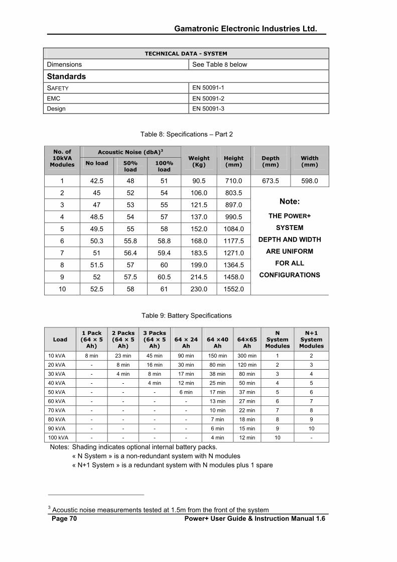
Gamatronic Electronic Industries Ltd.
Page 70 Power+ User Guide & Instruction Manual 1.6
TECHNICAL DATA - SYSTEM
Dimensions See Table 8 below
Standards SAFETY EN 50091-1
EMC EN 50091-2
Design EN 50091-3
Table 8: Specifications – Part 2
Acoustic Noise (dbA)3 No. of 10kVA
Modules No load 50% load
100% load
Weight
(Kg)
Height (mm)
Depth (mm)
Width (mm)
1 42.5 48 51 90.5 710.0 673.5 598.0
2 45 52 54 106.0 803.5
3 47 53 55 121.5 897.0
4 48.5 54 57 137.0 990.5
5 49.5 55 58 152.0 1084.0
6 50.3 55.8 58.8 168.0 1177.5
7 51 56.4 59.4 183.5 1271.0
8 51.5 57 60 199.0 1364.5
9 52 57.5 60.5 214.5 1458.0
10 52.5 58 61 230.0 1552.0
Note:
THE POWER+
SYSTEM
DEPTH AND WIDTH
ARE UNIFORM
FOR ALL
CONFIGURATIONS
Table 9: Battery Specifications
Load
1 Pack (64 × 5
Ah)
2 Packs (64 × 5
Ah)
3 Packs (64 × 5
Ah)
64 × 24
Ah
64 ×40
Ah
64×65
Ah
N System Modules
N+1 System Modules
10 kVA 8 min 23 min 45 min 90 min 150 min 300 min 1 2
20 kVA - 8 min 16 min 30 min 80 min 120 min 2 3
30 kVA - 4 min 8 min 17 min 38 min 80 min 3 4
40 kVA - - 4 min 12 min 25 min 50 min 4 5
50 kVA - - - 6 min 17 min 37 min 5 6
60 kVA - - - - 13 min 27 min 6 7
70 kVA - - - - 10 min 22 min 7 8
80 kVA - - - - 7 min 18 min 8 9
90 kVA - - - - 6 min 15 min 9 10
100 kVA - - - - 4 min 12 min 10 -
Notes: Shading indicates optional internal battery packs. « N System » is a non-redundant system with N modules « N+1 System » is a redundant system with N modules plus 1 spare
3 Acoustic noise measurements tested at 1.5m from the front of the system
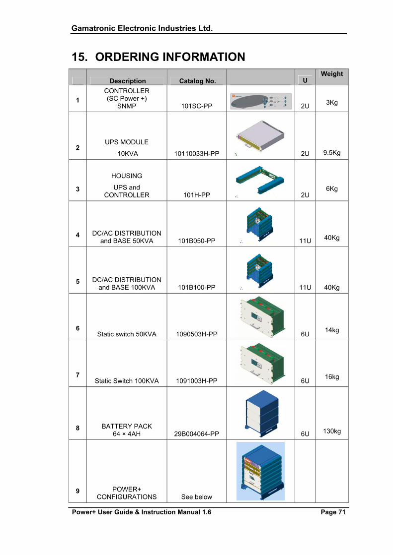
Gamatronic Electronic Industries Ltd.
Power+ User Guide & Instruction Manual 1.6 Page 71
15. ORDERING INFORMATION
Description Catalog No.
U Weight
1 CONTROLLER (SC Power +)
SNMP 101SC-PP 2U
3Kg
2 UPS MODULE
10KVA 10110033H-PP 2U
9.5Kg
3
HOUSING
UPS and CONTROLLER 101H-PP 2U
6Kg
4 DC/AC DISTRIBUTION and BASE 50KVA 101B050-PP 11U
40Kg
5 DC/AC DISTRIBUTION and BASE 100KVA 101B100-PP 11U
40Kg
6 Static switch 50KVA 1090503H-PP 6U
14kg
7 Static Switch 100KVA 1091003H-PP 6U
16kg
8 BATTERY PACK 64 × 4AH 29B004064-PP 6U
130kg
9 POWER+ CONFIGURATIONS See below
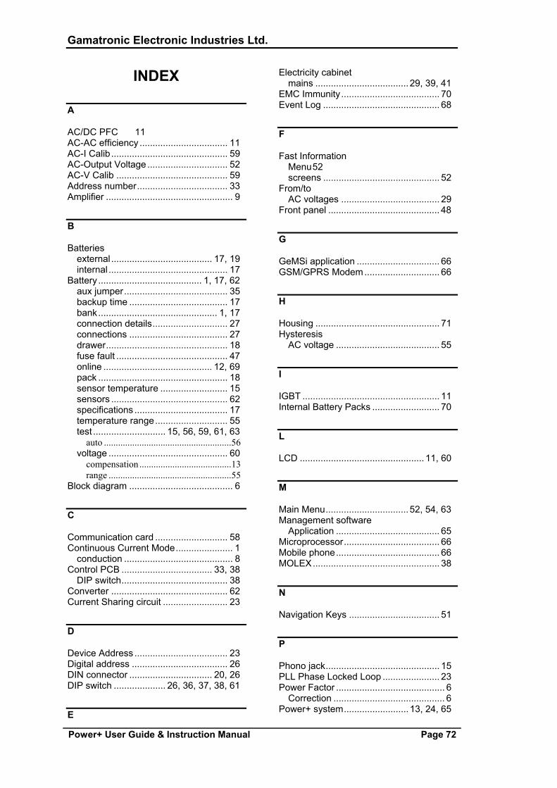
Gamatronic Electronic Industries Ltd.
Power+ User Guide & Instruction Manual Page 72
INDEX
A
AC/DC PFC 11 AC-AC efficiency .................................. 11 AC-I Calib............................................. 59 AC-Output Voltage ............................... 52 AC-V Calib ........................................... 59 Address number................................... 33 Amplifier ................................................. 9
B
Batteries external ....................................... 17, 19 internal .............................................. 17
Battery ........................................ 1, 17, 62 aux jumper........................................ 35 backup time ...................................... 17 bank.............................................. 1, 17 connection details............................. 27 connections ...................................... 27 drawer............................................... 18 fuse fault ........................................... 47 online .......................................... 12, 69 pack .................................................. 18 sensor temperature .......................... 15 sensors ............................................. 62 specifications .................................... 17 temperature range............................ 55 test ............................ 15, 56, 59, 61, 63
auto ......................................................56 voltage .............................................. 60
compensation .......................................13 range ....................................................55
Block diagram ........................................ 6
C
Communication card ............................ 58 Continuous Current Mode...................... 1
conduction .......................................... 8 Control PCB ................................... 33, 38
DIP switch......................................... 38 Converter ............................................. 62 Current Sharing circuit ......................... 23
D
Device Address .................................... 23 Digital address ..................................... 26 DIN connector ................................ 20, 26 DIP switch .................... 26, 36, 37, 38, 61
E
Electricity cabinet mains .................................... 29, 39, 41
EMC Immunity...................................... 70 Event Log ............................................. 68
F
Fast Information Menu 52 screens ............................................. 52
From/to AC voltages ...................................... 29
Front panel ........................................... 48
G
GeMSi application ................................ 66 GSM/GPRS Modem............................. 66
H
Housing ................................................ 71 Hysteresis
AC voltage ........................................ 55
I
IGBT ..................................................... 11 Internal Battery Packs .......................... 70
L
LCD ................................................ 11, 60
M
Main Menu................................52, 54, 63 Management software
Application ........................................ 65 Microprocessor..................................... 66 Mobile phone........................................ 66 MOLEX................................................. 38
N
Navigation Keys ................................... 51
P
Phono jack............................................ 15 PLL Phase Locked Loop ...................... 23 Power Factor .......................................... 6
Correction ........................................... 6 Power+ system......................... 13, 24, 65
Gamatronic Electronic Industries Ltd.
Power+ User Guide & Instruction Manual Page 73
cabling of .......................................... 39
R
Rectifier ................................................ 62 ID ...................................................... 61
S
Utilities.................................................. 57 Semiconductors ................................... 15 Service Mode ....................................... 57 Setup Menu.................................... 55, 57 Silicon................................................... 55 SNMP................................................... 58 Static Switch................................... 24, 33 System Controller..................... 24, 49, 50
Connections...................................... 33 display .............................................. 41
System menu ....................................... 42
T
THD........................................................ 6 Topology .................................. 11, 12, 69
DC/AC inverter principal................... 11 Transformer............................................ 1
U
UPS module 8, 11, 15, 20, 24, 26, 28, 29, 33,
48 basic.......................................................6 DC section ...........................................30 system..................................................25
shelf .................................................. 26 Utilities.................................................. 51
W
WING ............................................. 65, 66