power dissipation in car tyres - diva portal
TRANSCRIPT
Power Dissipation in Car Tyres
Martin Fraggstedt
Stockholm 2006
Licentiate ThesisTRITA-AVE 2006:26
ISSN 1651-7660
Royal Institute of TechnologySchool of Engineering Sciences
Department of Aeronautical and Vehicle EngineeringThe Marcus Wallenberg Laboratory for Sound and Vibration Research
Postal address Visiting address ContactRoyal Institute of Technology Teknikringen 8 Tel: +46 8 790 8015MWL / AVE Stockholm Fax: +46 8 790 6122SE-100 44 Stockholm Email:[email protected]


Abstract
Traffic is a major source of green house gases. The transport fieldstands for 32 % of the energy consumption and 28 % of the totalCO2 emissions, where road transports alone causes 84 % of these fig-ures. The energy consumed by a car traveling at constant speed, isdue to engine ineffiency, internal friction, and the energy needed toovercome resisting forces such as aerodynamic drag and rolling resis-tance. Rolling resistance plays a rather large role when it comes to fueleconomy. An improvement in rolling resistance of 10 % can yield fuelconsumption improvements ranging from 0.5 to 1.5 % for passengercars and light trucks and 1.5 to 3 % for heavy trucks.
The objective of this thesis is to estimate the power consumptionin the tyres. To do this a car tyre is modeled with waveguide finiteelements. A non-linear contact model is used to calculate the contactforces as the tyre is rolling on a rough road. The contact forces com-bined with the response of the tyre is used to estimate the input powerto the tyre structure, which determines a significant part of the rollingresistance.
The tyre model accounts for: the curvature, the geometry of thecross-section, the pre-stress due to inflation pressure, the anisotropicmaterial properties and the rigid body properties of the rim. The modelis based on design data. The motion of the tyre belt and side wall isdescribed with quadratic anisotropic, deep shell elements that includespre-stress and the motion of the tread on top of the tyre by quadratic,Lagrange type, homogenous, isotropic two dimensional elements.
To validate the tyre model, mobility measurements and an exper-imental modal analysis has been made. The model agrees very wellwith point mobility measurements up to roughly 250 Hz. The eigen-frequency prediction is within five percent for most of the identifiedmodes. The estimated damping is a bit too low especially for the anti-symmetric modes. Above 500 Hz there is an error ranging from 1.5 dBup to 3.5 dB for the squared amplitude of the point mobility.
The non proportional damping used in the model is based on an adhoc curve fitting procedure against measured mobilities.
The contact force predictions, made by the division of appliedacoustics, Chalmers University of Technology, are based on a non-linearcontact model in which the tyre structure is described by its flexibilitymatrix. Topographies of the surface are scanned, the tread pattern isaccounted for, and then the tyre is ’rolled’ over it. The contact forcesare inserted into the tyre model and the response is calculated. Thedissipated power is then calculated through the injected power and thepower dissipated within each element. Results are promising comparedto literature and measurements.


Licentiate Thesis
The thesis consists of an introduction and the following two papers:
Paper AFraggstedt M. and Finnveden S. A Waveguide Finite Element Model Of APneumatic Tyre, 2006. To be submitted.
Paper BFraggstedt M. and Finnveden S. Power dissipation in car tyres, 2006. To besubmitted.
Contribution from the author of this thesis
Paper AExperimental modal analysis and the mobility measurements. Performedsimulations. Fine tuning of the model developed by the supervisor. Writingthe paper.
Paper BPerformed the power calculations. Litterature study on rolling resistance.Writing the paper.
The material from this thesis has been presented at five workshops in theITARI project plus at three conferences:
SVIB, Nordic Vibration Research Conference, Stockholm Sweden,Fraggstedt M., Estimation of Damping in Car Tyres, 2004.
Novem conference 2005, Finnveden S., Nilsson C.-M. and Fraggstedt M.,Waveguide FEA of the Vibration of Rolling Car Tyres.
Euronoise 2006, Tampere, Finland, Fraggstedt M., Rolling Resistance OfCar Tyres, 2006.

.

Contents
1 Introduction 11.1 Background . . . . . . . . . . . . . . . . . . . . . . . . . . . . 11.2 Car tyres . . . . . . . . . . . . . . . . . . . . . . . . . . . . . 21.3 Waveguide finite elements . . . . . . . . . . . . . . . . . . . . 3
2 Summary of the papers 52.1 A waveguide finite element model of a pneumatic tyre . . . . 52.2 Power dissipation in car tyres . . . . . . . . . . . . . . . . . . 6
3 Future Work 7
4 Conclusion 8
5 Acknowledgements 8


1 Introduction
1.1 Background
For over fifty years traffic has been an irritating noise polluter. For higherspeeds tyres have been found to be the major contributor for traffic noise.Also the interior noise in the vehicle due to the tyres are becoming moreimportant as other noise sources such as engines, exhaust systems and gearboxes are better managed.
The negative effect on the environment has been highlighted for a numberof years, given that traffic is a major source of green house gases. Thetransport field is representing 32% of the energy consumption and 28% ofthe total CO2 emissions, where road transports alone stands for 84 % ofthese figures [1].
When it comes to the dynamics of the car the tyres are crucial, as theyprovide the grip required for cornering, braking and acceleration. In addi-tion, tyres are also highly involved in the cars handling abilities. As a finalpoint it is the tyres and the suspension system that assures a comfortableride.
The energy consumed by a car traveling at constant speed, is due to en-gine ineffiency, internal friction, and the energy needed to overcome resistingforces such as aerodynamic drag and rolling resistance, which is the topic ofthis thesis.
The rolling resistance Fr is defined as the energy consumed per unitof distance traveled [2]. The unit is Nm/m = N which is equivalent toa drag force in Newtons. Tyres are made of reinforced rubber, which is aviscoelastic material. As it deforms a part of the energy is stored elasticallybut the remainder is dissipated as heat. These hysteretic losses, as well asaerodynamic drag and friction in the contact patch and with the rim arelosses that contribute to the total drag force on a moving vehicle. Rollingresistance has a rather large impact when it comes to fuel economy. A 10% improvement in rolling resistance can give fuel consumption reductionsranging from 0.5 to 1.5 % for passenger cars and light trucks and 1.5 to 3% for heavy trucks [3].
Normally the rolling resistance is given as a dimensionless constant timesthe gravity force,
Fr = Cr m g, (1)
1

where m is the mass, g is the constant of gravity and Cr is the rolling resis-tance coefficient. Cr is normally in the range 0.01-0.02 with a typical valueof 0.012 for a passenger car tyre on dry asphalt [4]. The power consumedby this force is
P = V Fr = V Cr m g (2)
where V is the speed of the vehicle. In equation (1) the only explicit pa-rameter is the load. The variation with other parameters are concealed inCr. Studies has shown that the rolling resistance coefficient is influenced bya number of parameters such as speed, driving torque, acceleration, rubbercompound, internal and ambient temperature, road texture, road roughness,and wear. The model is however usually sufficient for some applications.
The aim of this thesis is to model a radial car tyre with waveguide finiteelements and to use this model to estimate the power dissipation as the tyreis rolling on a rough road. These losses determine a significant part of therolling resistance. The model was originally designed for tyre road noisepredictions.
The analytical investigations available in the literature are all based onrather simple equivalent structures. Stutts and Soedel [5] used a tensionband on a viscoelastic foundation. Kim and Savkoor [6] used an elastic ringsupported on a viscoelastic foundation. Yam et al [7] based there calculationon experimental modal parameters. Popov et al [8] modeled a truck tyre,based on the model developed by Kim and Savkoor [6]. The stiffness anddamping parameters needed, came from an experimental modal analysis.
The model used in this study has the correct geometry and stiffness pa-rameters as it is based on design data provided by the tyre manufacturerGoodyear. None of the models above are treating a rough road even thoughthe road texture and roughness have a significant effect on the rolling resis-tance [9].
1.2 Car tyres
Car tyres are made of several different materials including steel, fabric and ofcourse numerous rubber compounds, see Figure 1. To get different dynamicproperties in the tyre sub regions the materials are used in many ways.The three major sub regions of the tyre are the upper side wall, the lowerside wall and the central area. The ply is a layer of embedded fabric inthe rubber. At the lower side walls the ply encloses a volume filled withboth steel wires and hard rubber materials, this makes the lower side wallareas relatively stiff. The upper side wall areas are on the other hand quiteflexible, since the ply layer there is simple and there is less steel in there.The central area consists of the belt and the tread. The belt consists of arubber embedded steel lining (breakers) in the circumferential direction togive support and rigidity. The tread is an about 13 mm thick rubber layerwhich is there to provide the grip. This makes the central area rigid with
2
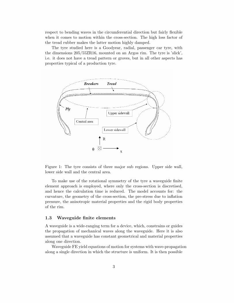
respect to bending waves in the circumferential direction but fairly flexiblewhen it comes to motion within the cross-section. The high loss factor ofthe tread rubber makes the latter motion highly damped.
The tyre studied here is a Goodyear, radial, passenger car tyre, withthe dimensions 205/55ZR16, mounted on an Argos rim. The tyre is ’slick’,i.e. it does not have a tread pattern or groves, but in all other aspects hasproperties typical of a production tyre.
Figure 1: The tyre consists of three major sub regions. Upper side wall,lower side wall and the central area.
To make use of the rotational symmetry of the tyre a waveguide finiteelement approach is employed, where only the cross-section is discretised,and hence the calculation time is reduced. The model accounts for: thecurvature, the geometry of the cross-section, the pre-stress due to inflationpressure, the anisotropic material properties and the rigid body propertiesof the rim.
1.3 Waveguide finite elements
A waveguide is a wide-ranging term for a device, which, constrains or guidesthe propagation of mechanical waves along the waveguide. Here it is alsoassumed that a waveguide has constant geometrical and material propertiesalong one direction.
Waveguide FE yield equations of motion for systems with wave-propagationalong a single direction in which the structure is uniform. It is then possible
3

to separate the solution to the wave equation into one part depending onthe cross-section, one part depending on the coordinate along the waveguideand one part depending on time.
As an example of a waveguide a generalised beam, in which longitudinal,torsional, shearing and flexural waves can travel, can be considered. Themain idea with a waveguide approach is to study waves propagating in thestructure.
The most important benefit with waveguide FE is that it decreases thecalculation time compared to ordinary finite elements since only the cross-section has to be discretised and the number of degrees of freedom is re-duced. Another advantage compared to conventional FE methods is that itis straight forward to identify and analyse different wave types, which allowsa physical understanding of the structure under investigation. The abilityto handle infinite waveguides is an additional good feature of this method.
Forced response solutions for waveguide FE models can be handled inseveral different ways. Four of these methods for forced responses will bebriefly explained.
For infinite waveguides an approach based on Fourier transforms maybe used. The equations of motion are transformed to the wave number do-main through a spatial Fourier transform. The solution in the wave numberdomain then has to be transformed back to the spatial domain through aninverse Fourier transform which generally involves residue calculus [10].
’Super Spectral Elements’, (SSE), are derived by using wave solutions,given from a generalised eigenvalue problem, as test and shape functionsin the variational form of the wave equation [11]. At the ends, the spec-tral elements can be coupled to other spectral elements or to regular finiteelements.
A modal solution is suited for a structure with rotational symmetry, suchas a car tyre. The response is assumed to be a sum of the waves (eigen-vectors) with real integer wave numbers, resulting from a twin parametereigenvalue problem. The amplitude of these waves are then treated as un-knowns in the strong form of the wave equation. The wave equation is thenmultiplied with one specific eigenvector and the result is integrated over thelength of the waveguide. The orthogonality between the eigenvectors, overthe length of the waveguide, filters out the coefficients corresponding to theeigenvector. The non-proportional damping used in the present analysis,however, leads to non-orthogonal eigenvectors and therefore this method isnot used.
In an assumed modes procedure the response is assumed to be an expo-nential Fourier series in the spatial domain. This approach is suitable, sincethe tyre is a circular structure and the solutions to the wave equation will beperiodic with respect to the circumferential angle. The sum is inserted intothe variational statement, and upon variation follows the equations of mo-tion. The advantage with this direct methodology in the frequency domain
4
is that is uncomplicated to handle fluid-structure interactions. The car tyreincluding the air cavity has been modeled successfully by Nilsson [10] with awaveguide FE approach similar to the one presented here. Also, frequencydependant materials are easily included. This is an especially good qualitywhen considering a structure such as a car tyre, which is built from rubber,whose material properties show a strong frequency dependency. This is theprocedure used in the present analysis.
Straight waveguide finite elements were first formulated by Alaami [12]and Lagasse [13] in 1973. Curved waveguides are used by Hladky-Hennion[14] and Nilsson [10]. The elements in the present tyre model are describedin [15]. In reference [10] there is a comprehensive review of the applicationsof waveguide FE for vibro-acoustic problems.
2 Summary of the papers
2.1 A waveguide finite element model of a pneumatic tyre
A waveguide finite elements model based on design data is used to describethe dynamic properties of a passenger car tyre. The response of the tyrebelt and side wall is described with quadratic anisotropic, deep shell elementsthat include pre-stress and the motion of the tread on top of the tyre byquadratic, Lagrange type, isotropic two dimensional elements.
To validate the tyre model, mobility measurements and an experimen-tal modal analysis has been made. The calculations agrees very well withmeasurements up to roughly 250 Hz for the radial point mobilities, see Fig-ures 2 and 3 for excitation in the middle of the tread. The eigenfrequencyprediction are within five percent for the identified modes, except for theaxial semi rigid body mode (error 12 %), the anti-symmetric mode of ordertwo (error 10 %) and the anti-symmetric mode of order seven (error 7 %).The estimated damping, especially for the anti-symmetric modes, is a bittoo low.
The ’cut-on’ frequency, of the belt bending modes, is the lowest frequencyat which the corresponding waves are propagated. It comes earlier in theprediction than in the measurement. This is perhaps due to ageing of thetyre since comparable measurements performed in the spring of 2001 [16] isin agreement with the calculation. In the range 500 -1000 Hz there is anerror ranging from 1.5 dB up to 3.5 dB for the squared amplitude of thepoint mobility. For the transfer mobilities, the error is larger since they aremore sensitive to the exact position of the accelerometer, particularly so forthe anti-resonances, see Figure 4.
The non proportional damping is found with an ad hoc curve fittingprocedure based on the measured mobilities.
5
2.2 Power dissipation in car tyres
The tyre model described in Paper A is used to estimate the power consumedby visco elastic losses. External forces resulting from a non-linear contactmodel, for three different roads are inserted and the responses are calculated.The dissipated power is then equated to the injected power as well as to thesum of the power dissipated within the elements.
The contact force predictions are made by Frederic Wullens of the di-vision of applied acoustics, Chalmers University of Technology (CTH) asdescribed in reference [17]. It is based on a non-linear contact model inwhich the response of the tyre is described with its flexibility matrix . To-pographies of the surface are scanned, the tread pattern is accounted for,and then the tyre is ’rolled’ over it in the time domain. The nonlinear con-ditions used are: i) the tyre cannot indent into the road, ii) if a point isnot in contact the force is zero and iii) the force cannot be negative (roadpulling tyre down). Only forces acting normal to the road is considered.
The contact forces are used to calculate the response of the tyre. Whenthe forces and the motion is known the injected power can be calculated. Thepredicted power dissipation compares favorably with those from literature[4] and with measurements. The power dissipation is larger on the roughroad than on the smooth road, this showing the great influence of the road onthe rolling resistance. To the best of the author’s knowledge, this influenceis neglected in all previous works.
The dissipated power for a test road managed and scanned by Renault,as a function of frequency and wave order can be seen in Figure 5 and 6respectively. The reason that the frequency spectrum looks so rough is thatonly two revolutions have been used for the calculation. If the contact forceswere truly periodic every other frequency component would cancel out. Byusing more non identical revolutions the result would probably look muchsmoother. A significant part of the dissipation occurs below 100 Hz and ata wave order around 3.
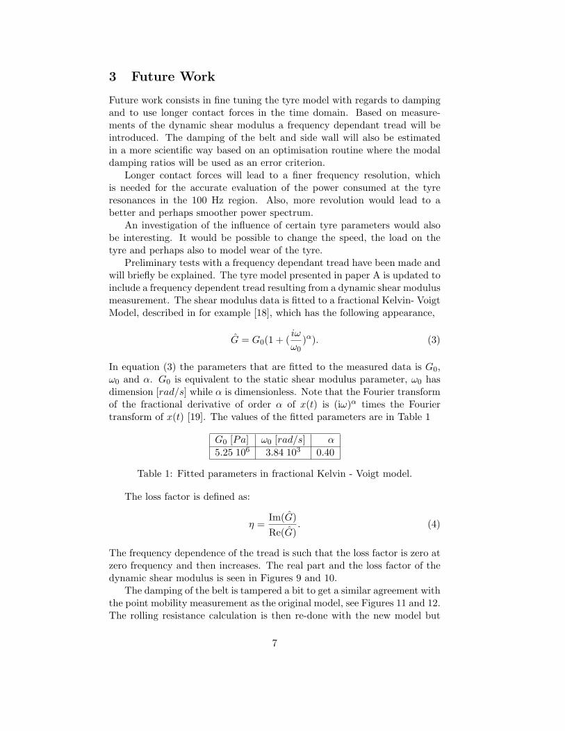
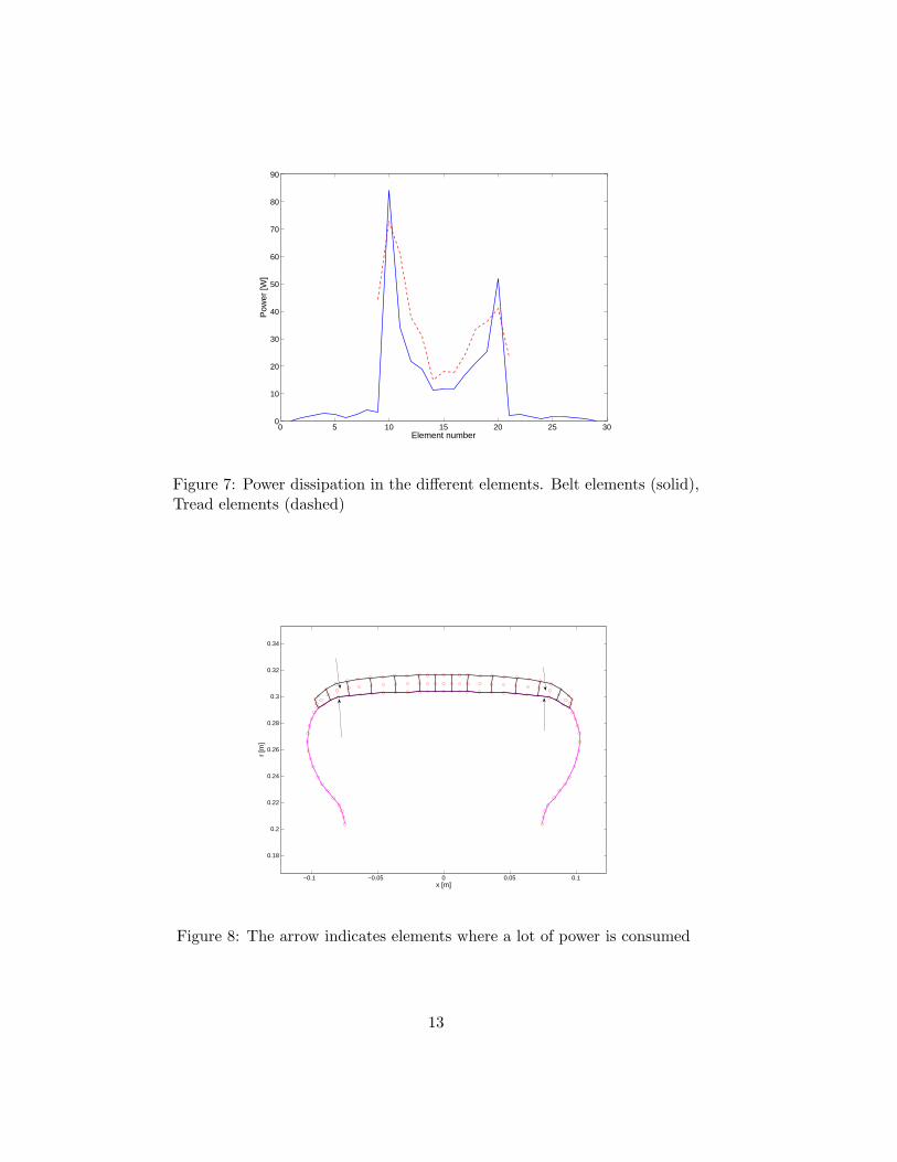
By studying the power dissipated within the elements it can be concludedthat there are nearly no losses occurring in the side wall, see Figures 7 and8, which is in conflict with [3] who says that roughly 30 % of the totaldissipated power appears in the upper and lower side wall. The overalldamping level in the model is estimated quite accurately (see Paper A), butthe distribution of the damping, in the different parts of the tyre, is probablywrong. Since the visco elastic data is very important for a rolling resistanceprediction, the damping should be established in a more scientific way, andthis development will be reported at a later stage.
6
3 Future Work
Future work consists in fine tuning the tyre model with regards to dampingand to use longer contact forces in the time domain. Based on measure-ments of the dynamic shear modulus a frequency dependant tread will beintroduced. The damping of the belt and side wall will also be estimatedin a more scientific way based on an optimisation routine where the modaldamping ratios will be used as an error criterion.
Longer contact forces will lead to a finer frequency resolution, whichis needed for the accurate evaluation of the power consumed at the tyreresonances in the 100 Hz region. Also, more revolution would lead to abetter and perhaps smoother power spectrum.
An investigation of the influence of certain tyre parameters would alsobe interesting. It would be possible to change the speed, the load on thetyre and perhaps also to model wear of the tyre.
Preliminary tests with a frequency dependant tread have been made andwill briefly be explained. The tyre model presented in paper A is updated toinclude a frequency dependent tread resulting from a dynamic shear modulusmeasurement. The shear modulus data is fitted to a fractional Kelvin- VoigtModel, described in for example [18], which has the following appearance,
G = G0(1 + (iω
ω0)α). (3)
In equation (3) the parameters that are fitted to the measured data is G0,ω0 and α. G0 is equivalent to the static shear modulus parameter, ω0 hasdimension [rad/s] while α is dimensionless. Note that the Fourier transformof the fractional derivative of order α of x(t) is (iω)α times the Fouriertransform of x(t) [19]. The values of the fitted parameters are in Table 1
G0 [Pa] ω0 [rad/s] α
5.25 106 3.84 103 0.40
Table 1: Fitted parameters in fractional Kelvin - Voigt model.
The loss factor is defined as:
η =Im(G)Re(G)
. (4)
The frequency dependence of the tread is such that the loss factor is zero atzero frequency and then increases. The real part and the loss factor of thedynamic shear modulus is seen in Figures 9 and 10.
The damping of the belt is tampered a bit to get a similar agreement withthe point mobility measurement as the original model, see Figures 11 and 12.The rolling resistance calculation is then re-done with the new model but
7

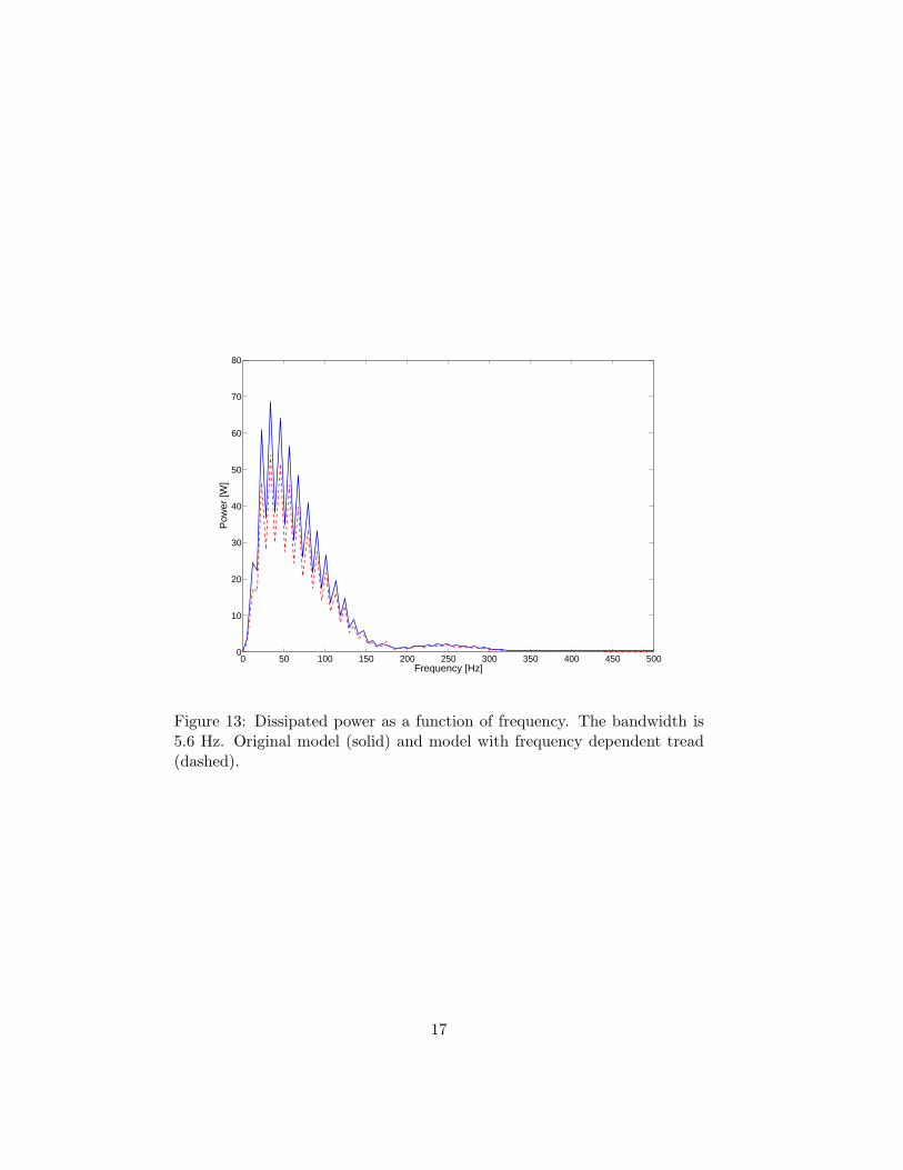
with the old contact forces. The contact forces calculation depends on theflexibility matrix of the tyre, so the result should be interpreted with care.For the Renault road the original model gave a total power loss of 805.7Watts whereas the model with frequency dependent tread gives a value of645.0 Watts.
The main part of the power loss occur around 50 Hz where the lossfactor, from the measurements of the tread is much smaller (η = 0.16) thanthe one used in the original model (η = 0.3) the losses are consequentlyreduced. See Figure 13 for the power loss versus frequency for the originaland the new model.
4 Conclusion
A car tyre is modeled with wave guide finite elements. The model is em-ployed to calculate the power dissipation as the tyre is rolling on a roughroad showing promising agreement with measurements. The road roughnessis seen to have a significant effect on the dissipated power, which, to the bestof the authors’ knowledge, is neglected in all previous works
5 Acknowledgements
The early development of the tyre model was funded by the Swedish Re-search Council (621-2002-5661) and the European Commission (G3RD-CT-2000-00097). Many thanks to the members of the Ratin consortium and inparticular to Roger Pinnington, ISVR, for helpful discussion, to WolfgangGnorich and Andrzej Pietrzyk, Goodyear, for advice and for sharing datafor tyres and to Wolfgang Kropp, Patrik Andersson and Frederic Wullens,Applied Acoustics, Chalmers, for advise and calculation of contact forces.The final tyre model and the work presented in this thesis were funded bythe European Commission, ITARI, FP6-PL-0506437. The measurement ofrolling resistance was made by Gdansk University of Technology.
I would also like to thank to Ulf Carlsson, Kent Lindgren and DaniloPrelevic for assisting me with the measurements, and Dr Jenny Jerrelind forher suggestions on the outline of this thesis. Special thanks to Carl-MagnusNilsson. Finally i would like to thank my family, my friend and the peopleat MWL.
References
[1] COM 370, White Paper, European transport policy for2010: time to decide, 2001.
8

[2] ISO 18164 Passenger car, truck, bus and motorcycle tyres- Methods of measuring rolling resistance, 2005.
[3] Hall D.E. and Moreland J.C. Fundamentals of rolling re-sistance, Rubber Chemistry and Technology 74 (3): 525-539 JUL-AUG, 2001.
[4] Wennerstrm E. Fordonsteknik, 8th edition, in swedish,KTH, 2004.
[5] Stutts D.S. and Soedel W. A Simplified Dynamic Modelof the Effect of Internal Damping on the rolling resistancein pneumatic tires, Journal of Sound and Vibrarion 155(1), 153-164, 1992.
[6] Kim S.-J., and Savkoor A.R. The Contact Problem of In-Plane Rolling of Tires on a Flat Road, Vehicle SystemDynamics Supplement 27, pp. 189-206, 1997.
[7] Yam L.H., Guan D.H., Shang J. and Zhang A.Q. Study ontyre rolling resistance using experimental modal analysis,Int. J. Vehicle Design, Vol. 30, No. 3, pp. 251-262, 2002.
[8] Popov A.A., Cole D.J., Cebon D. and Winkler C.B. En-ergy Loss in Truck Tyres and Suspensions. Vehicle SystemDynamics Supplement 33 , pp. 516-527, 1999.
[9] Hoogvelt R.B.J., Hogt R.M.M., Meyer M.T.M. andKuiper E. Rolling resistance of passenger car andheavy vehicle tyres a literature survey, TNO report01.OR.VD.036.1/RH, December 11th 2001.
[10] Nilsson C.-M. Waveguide finite elements applied on a cartyre. Doctorial thesis. Aeronautical and Vehicle Engineer-ing, KTH 2004.
[11] Birgersson F., Finnveden S. and C.-M. Nilsson. A spectralsuper element for modelling of plate vibration. Part 1:general theory, Journal of Sound and Vibration 287 (2005)297314.
[12] Alaami B. Waves in prismatic guides of arbitrary crosssection. Journal of Applied Mechanics, (December):1067-1071, 1973.
[13] Lagasse P.E. Higher-order finite-element analysis of to-pographic guides supporting elastic surface waves. TheJournal of the Acoustical Society of America Volume53(4):1116-1122, 1973.
9

[14] Hladky-Hennion A.-C. Finite element analysis of thepropagation of acoustic waves in waveguides. Journal ofSound and Vibration, 194(2), 119-136, 1996.
[15] Finnveden S., Fraggstedt M. Waveguide finite elementsfor curved structures, TRITA-AVE 2006:38.
[16] Andersson P. High Frequency tyre vibration. Lic. thesis,Chalmers University of Technology, 2002.
[17] Wullens F. Excitation of tyre vibrations due to tyre/roadinteraction, PhD thesis, Applied Acoustics, ChalmersUniversity of Technology, 2004.
[18] Koeller R. C. Applications of fractional calculus to thetheory of viscoelasticity Transactions of the American So-ciety of Mechanical Engineers Journal of Applied Mechan-ics 51, 299-307, 1984.
[19] Bagley R. L. and Torvik P. J. Fractional calculus-A dif-ferent approach to the analysis of viscoelastically dampedstructures, American Institute of Aeronautics and Astro-nautics Journal21, 741-748, 1983.
101
102
103
−70
−65
−60
−55
−50
−45
−40
−35
Frequency [Hz]
Mag
nitu
de o
f poi
nt m
obili
ty d
B r
el 1
(m
/Ns)
2
Figure 2: Magnitude of point mobility for excitation in the middle position.Measured (solid) and calculated (dashed).
10

101
102
103
−2
−1.5
−1
−0.5
0
0.5
Frequency (Hz)
Pha
se o
f poi
nt m
obili
ty (
rad)
Figure 3: Phase of point mobility for excitation in the middle position.Measured (solid) and calculated (dashed).
101
102
103
−100
−90
−80
−70
−60
−50
−40
Frequency [Hz]
Mag
nitu
de o
f tra
nsfe
r m
obili
ty d
B r
el 1
(m
/Ns)
2
Figure 4: Magnitude of transfer mobility for excitation in the middle posi-tion. The response is measured 23.5 cm avay in the circumferewntial direc-tion and 4.3 cm above the geometric centre. Measured (solid) and calculated(dashed).
11

0 50 100 150 200 250 300 350 400 450 5000
10
20
30
40
50
60
70
80
Frequency [Hz]
Pow
er [W
]
Figure 5: Dissipated power as a function of frequency. The bandwidth is5.6 Hz. Most of the dissipation occurs below 100 Hz.
0 5 10 15 20 25 300
20
40
60
80
100
120
Waveorder
Pow
er [W
]
Figure 6: Dissipated power as a function of wave order. A substantial partof the dissipated power occur at a wave order of around 3.
12
0 5 10 15 20 25 300
10
20
30
40
50
60
70
80
90
Element number
Pow
er [W
]
Figure 7: Power dissipation in the different elements. Belt elements (solid),Tread elements (dashed)
−0.1 −0.05 0 0.05 0.1
0.18
0.2
0.22
0.24
0.26
0.28
0.3
0.32
0.34
x [m]
r [m
]
Figure 8: The arrow indicates elements where a lot of power is consumed
13

0 200 400 600 800 1000 12007
7.5
8
8.5
9
9.5
10
10.5
11
11.5
12x 10
6
Frequency [Hz]
Re(
G)
[Pa]
Figure 9: Real part of dynamic shear modulus. Measured (solid) and cal-culated with equation (3) (dashed)
0 200 400 600 800 1000 12000.18
0.2
0.22
0.24
0.26
0.28
0.3
0.32
0.34
0.36
0.38
Frequency [Hz]
Loss
fact
or
Figure 10: Measured (solid) and calculated with equation (3) (dashed) loss-factor.
14

101
102
103
−70
−65
−60
−55
−50
−45
−40
−35
Frequency [Hz]
Mag
nitu
de o
f poi
nt m
obili
ty d
B r
el 1
(m
/Ns)
2
Figure 11: Magnitude of point mobility for excitation in the middle position.Measured (solid), original model (dashed) and new model with frequencydependent tread (dotted).
15

101
102
103
−2
−1.5
−1
−0.5
0
0.5
Frequency (Hz)
Pha
se o
f poi
nt m
obili
ty (
rad)
Figure 12: Phase of point mobility for excitation in the middle position.Measured (solid), original model (dashed) and new model with frequencydependent tread (dotted).
16
0 50 100 150 200 250 300 350 400 450 5000
10
20
30
40
50
60
70
80
Frequency [Hz]
Pow
er [W
]
Figure 13: Dissipated power as a function of frequency. The bandwidth is5.6 Hz. Original model (solid) and model with frequency dependent tread(dashed).
17