power disturbance management in captive power …ninl.in/web/portals/0/pdf/k-bank_akpanda.pdf ·...
TRANSCRIPT

NEELACHAL ISPAT NIGAM LTD
NINL Internal Page 1
Power Disturbance Management in Captive Power Plants
Date:19.09.2017
Name: A K Panda
Email ID: [email protected]
K-Bank
NEELACHAL ISPAT NIGAM LTD
NINL Internal Page 2
Confidentiality Statement The information in the document mentioned is not confidential and have been taken references from various sources as specified.
Abstract
Captive power plants have the dual objectives of ensuring uninterrupted power supply
to their process plant and also to stay connected with the grid to ensure export of
surplus power from their generating sets or import power from grid in case of shortfall.
Power disturbance, whether internal or external to the CPP, is a serious threat in the
path of fulfillment of these objectives of the CPP.
With increased industrialization number of consumers of bulk power has increased
many folds with a simultaneous increase in power disturbance.
So managing power disturbances has become a real challenge for CPPs.
Employment of suitable protection relays to deal with different types of internal
disturbances and a suitable islanding system to deal with external disturbances are the
main points of discussion of the subject.
Protection relays used in two different plants may be identical but relay settings of two
different plants will vary depending upon the total generation, load, grid condition and
NEELACHAL ISPAT NIGAM LTD
NINL Internal Page 3
so many other factors.
The subject deals with the way of management of both internal and external
disturbances by the CPPs with specific reference to the system adopted at NINL.
About the Author
A K Panda, DGM (PP). He is associated with NINL for the last 20 years.
Intended Readers
All steel plant employees
Description
Power System
A power system consists of the following sub systems
1. Power Generation system
2. Power Transmission system
3. Power Distribution system
The power system network can become unstable due to disturbance in any of the
above subsystems.

NEELACHAL ISPAT NIGAM LTD
NINL Internal Page 4
Captive Power Plant
A captive power plant, as the name suggests, is where the power generated by the
plant is consumed within that plant boundary only. But at present that definition has
undergone slight modification. A power plant is called captive if major portion of the
power generation is consumed within the plant boundary by internal consumers. So a
captive power plant always coexists with a process plant. The process plant can be a
steel plant, an aluminum plant, sugar plant, oil refinery etc. In all such cases power
generation is not the prime job of these plants. Captive Power plant is just a service
provider for the process plant.
Grid
The transmission network, which receives power from generating stations and
supplies power to large utilities, is called grid. So grid is basically a HT distribution
network.
Requirement of grid connection for CPPs
The basic purpose of any captive power plant is to supply reliable power to the
process requirements. Captive power plants run in synchronized condition with
grid supply for two purposes.
1. To give reliability to the power supply for the process by ensuring
uninterrupted supply in the event of failure of the captive units or in the
event of inadequacy of the captive generation to meet the process
requirement.
2. To export the surplus power, if any, to grid to earn additional revenue.
Sale of power has become equally important in view of the permanent demand-
supply gap and increased realization from sale of power after reforms in electricity
sector.
So captive power plants have the dual responsibility of ensuring stable power supply
for their process plants and to earn revenue from sale of power. But the responsibility

NEELACHAL ISPAT NIGAM LTD
NINL Internal Page 5
of feeding power to the process has a priority over power export.
Disturbance
Disturbance in the power system is mainly variation in system voltage and
frequency beyond permissible limit.
The captive power plants face disturbance in the power system both from external
and internal sources.
Internal disturbance
Internal disturbance is disturbance in the power supply network, which is inside
the plant where the CPP is located.
Typical power network of a CPP
Usually a CPP consists of more than one generating unit. The generating units
generate power at 6.6 KV or 11 KV.
If generation and distribution inside the plant is at 6.6 KV, then voltage from the
grid is stepped down to 6.6 KV and generating sets are synchronized at 6.6 KV
level.
In case of bigger plants, distribution inside the plant is at 33 KV level. The power
generated at 11 KV is stepped up to 33 KV by generator transformers. Power
received from grid is stepped down to 33 KV. In this case synchronization is done
at 33 KV level.
In side the plant there is extensive power distribution network supplying power to
various shops. Depending upon the type of process, the number of shops in side
the plant will increase.
The different possible reasons of power disturbance can be due to
1. fault in the generating system
2. fault in the distribution system

NEELACHAL ISPAT NIGAM LTD
NINL Internal Page 6
3. fault in the end use equipment
Faults in the generating system
Faults of the generating system can be divided in to 3 categories.: faults in the generator,
faults in the generator transformer and faults in the turbine.
Faults in the generator are
a. Stator over current
b. Voltage restrained over current
c. Stator earth faults( 95 % and 100 %)
d. Stator Differential current
e. Over load
f. Over voltage
g. Unbalanced loading/negative sequence
h. Over fluxing
i. Rotor earth faults
j. Loss of excitation
k. Loss of synchronism or out of step
l. Failure of prime mover
Faults of the generating transformer are
a. Over current
b. Earth fault
c. High oil / winding temperature
d. Transformer differential current
e. Other transformer faults like buchholtz, PRV
NEELACHAL ISPAT NIGAM LTD
NINL Internal Page 7
Faults of the turbine are
a. Lubrication oil failure
b. Over speed
c. High vibration
d. Low vacuum
m. Difference in expansion between rotating and stationary parts
e. High bearing temperature
f. High axial displacement
Tripping of the turbine due to any of the above reason will lead to tripping of the
generator on failure of prime mover protection of generator.
All the faults of the generator are classified in to 3 types of faults: class A, B & C.
Class – A faults are electrical faults, which will require tripping of both generator and
turbine.
Class - B faults are faults of the turbine and the generator will trip as a result of
turbine trip.
Class - C faults are electrical faults for which only the generator breaker will be
opened but turbine will be kept running.
When the generator is running in synchronism with grid, out of the above faults only over
current and earth fault type of faults have a potential to create immediate disturbance in the
power system. All other faults are going to affect that particular generator only.
Since the CPP is connected with grid, additional power requirement because of tripping of a
running generator will be supplemented by grid. So the power system will not experience any
disturbance in voltage or frequency. However tripping of the generator will affect the
export/import scenario of the plant ability of the CPP to run in isolation.
Management of disturbance in the generating system is a two fold approach
a. proactive measures to prevent generating system failure
b. Fast removal of faulty generating system from the network to minimize
disturbance.
NEELACHAL ISPAT NIGAM LTD
NINL Internal Page 8
The generator and turbine are monitored by online systems for temperature, vibration, axial
displacement, lubrication etc. The loading of the turbine is regulated to avoid too fast loading
and unloading to avoid thermal stress on turbine.
Fast acting numerical relays are provided to trip the generating unit in case of any of these
faults being sensed by the system. Generator protection consists of composite generator
protection relay, composite transformer protection relay, separate protection relays for stator
earth fault and rotor earth fault relay
Faults in the distribution system
Faults in the distribution system can be faults in the supply feeders or faults in the
distribution transformers. They will be mainly of over current and earth fault type and
other faults of the transformer. To minimize disturbance to the power system fast
acting over current, earth fault and transformer protection relays are provided to clear
such type of faults.
Fault in the end use equipment
End use equipment in the industry is mainly motors to drive various type of equipment like
pumps, fans etc. The different possible faults of a motor are
a. Over load
b. Long starting time
c. Locked rotor
d. Short circuit
e. Earth fault
f. High winding temperature
g. Negative sequence current
h. Under voltage
i. High vibration
j. Out-of-step ( for synchronous motors)

NEELACHAL ISPAT NIGAM LTD
NINL Internal Page 9
Fast acting composite numerical motor protection relays are provided to detect each of the
faults at an early stage and isolate the faulty equipment from the system to protect the power
system from serious damage. It is to be noted that a motor protection relay is not always to
protect the motor, it is more required to isolate a faulty motor in order to protect the power
system form possible disturbance.
Time grading of relays
Faults of over current and earth fault in nature create a disturbance in the power
supply network. This disturbance is felt all over the network.
Protection relays provided for different equipment are programmed in such a manner to
isolate a faulty system in the quickest possible time with minimum possible power interruption
for process equipments. Fast fault clearance and selective tripping is achieved by proper
current and time gradation of the protection relays.
External disturbance
External disturbance is experienced because of a disturbance in the HT
transmission and distribution system i.e the grid.
Disturbance in the grid supply originates from the following reasons
1. Earth fault/phase fault in the system- it will create dip in system voltage
2. Sudden outage of a generating unit- it will result in dip in frequency
3. Sudden outage of a large load- it will result in increase in system
frequency.
4. Power failure in the grid(momentary or longer duration)
A grid is said to be disturbed when :
a) there is an under voltage (U/V)
b) there is over voltage (O/V)
c) there is a rapid fall or rise in voltage(+ dv/dt or –dv/dt)
NEELACHAL ISPAT NIGAM LTD
NINL Internal Page 10
d) there is under frequency (U/F)
e) there is over frequency (O/F)
f) there is a rapid fall or rise in frequency ( +df/dt or –df/dt )
g) there is a power failure in the grid
Grid also deploys protection relays for fast fault clearance with selective tripping of
supply networks. However the captive power plants, which have a greater
responsibility to protect their process plants from power disturbance, cannot wait till
such time for the grid to clear the disturbance. If the disturbance persists for a longer
period or increases in intensity it will cause serious damage to process equipment and
to process.
To save their process and process equipment from likely damage due to power
disturbance from grid side, captive power plants resorts to islanding.
Islanding
Islanding is the process of disconnection of the captive power plant from the grid
and running in isolation.
Need of Islanding
As the grid is connected to a number of generating stations and consumption centers
at the same time, because of continuous variations in generating condition and
consumption pattern, it always fluctuates with respect to voltage and frequency.
Equipments of all the plants are subjected to this variation in voltage and frequency.
Disturbed condition of the grid create additional stress on equipments and can
destabilize the electrical system.

NEELACHAL ISPAT NIGAM LTD
NINL Internal Page 11
Islanding is required for power system stability. Islanding is required by both the grid
and CPP owner. Islanding helps both the Grid as well as the CPP owner in maintaining
power system stability.
Benefits to Grid
The Grid normally does not want an additional independent power source in their grid
network, when the grid is disturbed. Since the power source is not in their control, it
will complicate grid’s methods of dealing with the disturbed grid. While the grid is in
the process of solving the grid disturbance, they do not like to have another power
source which they do not control and which may add to the disturbance. Once the
non grid power source is disconnected from the grid, it becomes easier for them to
locate the source of disturbance and rectify the same. The main idea is that grid
eliminates the possibility of the CPP feeding the disturbance. Hence the availability of
the Grid islanding scheme in the CPP owner’s premises is a precondition for allowing
the CPP to be connected to grid.
Benefits to CPP owner:
It is strongly advisable to disconnect the captive power plant from the grid, when the
grid is disturbed. The main reason is that the generating sets may get spoilt due to
grid disturbances resulting in heavy repair costs and shut downs. Since grid is the
infinite source, the voltage and frequency of CPP is dictated by grid. Adverse voltage
and frequency condition of the grid will affect the process equipment and hence
process of the CPP.
It is also required that in the event of grid failure, the CPP must be disconnected from
the grid. This is to prevent collapse of the CPP as it will try to feed power to the entire
NEELACHAL ISPAT NIGAM LTD
NINL Internal Page 12
grid. Also when power comes back in to the grid, it will not be in synchronism with
the CPP power. If not disconnected it will cause very serious damage to the power
system equipments of the CPP. Hence the CPP is required to put an islanding scheme
when the CPP has to operate in parallel with the grid.
Grid Islanding Scheme
Grid Islanding scheme is a set of protective relays, connected at the incomer bus –
these relays will sense a disturbance in the grid and give a trip command to the
incomer breaker whenever the grid disturbance exceeds a set limit. By opening the
incomer breaker, the plant is isolated from the grid. The plant as well as the
generating sets are disconnected from the disturbed grid by the grid islanding
scheme.
Islanding Criteria
The following are different criteria for islanding.
Under voltage and over voltage (U<, U>)
Islanding due to grid under voltage and over voltage is required to minimize the risk
to equipments of the CPP. Loaded motors, for instance, need a higher current when
the mains voltage is reduced and this can result in thermal overload or even stalling
The grid voltage is monitored for both under voltage and over voltage conditions at
the point of islanding. When voltage changes beyond the set limit islanding of the CPP
is effected. Islanding because of under voltage and over voltage is always effected
with a time delay to avoid unwanted islanding. For example, start of a motor can also

NEELACHAL ISPAT NIGAM LTD
NINL Internal Page 13
cause a short term voltage drop which has to be permissible. A suitable time delay
will help in filtering out nuisance islanding.
Rate of change of voltage
Apart from under voltage and over voltage, the rate of change of voltage is also
monitored for effecting an islanding. Unlike the criteria of under voltage and over
voltage where the process equipment are subjected to certain amount of adverse
voltage conditions, monitoring the rate of change of voltage for islanding helps in
avoiding the adverse voltage condition being experienced by the process equipment.
Voltage unbalance
A voltage unbalance relay monitors the symmetry of voltage vectors in three-phase systems.
Resolving of a vector system into symmetrical components
· Positive phase-sequence system U1
· Negative-phase sequence system U2
· Zero-phase sequence system U0
is a method commonly used.
When a short circuit occurs in one phase or two phases, the voltage vectors of the faulty
phases deviate from their normal values. This effect is reflected in rise of the amplitude of the
negative phase sequence system and in voltage drop of the positive phase-sequence system.
The amplitude of the zero-phase sequence system is a quantity for displacement of the
voltage vector star point from its normal position. This is used as a criteria for islanding.
Power flow
With this protection method the direction of the electrical energy flow at the islanding point is
monitored. But this criteria for islanding is employed when the CPP always imports power .
This criteria can not be employed if the CPP is exporting power to the grid.

NEELACHAL ISPAT NIGAM LTD
NINL Internal Page 14
If the CPP is in export mode, a low forward power relay is used to detect the grid
failure. However since CPP is also likely to import power during shortfall in generation,
low forward power cannot be a foolproof method of detecting a grid failure to effect
an islanding.
So for plants with constant energy export or with changing energy flow direction power
monitoring relays are used in combination with other relays.
Over frequency/under frequency (f> , f<)
The frequency of the grid network will increase if the total power of generating stations
connected to the grid is more than the load connected to the grid and vice versa.The grid is
considered to be the infinite bus. The CPP which has a very small power generation as
compared to the grid can not change the frequency of the grid.Since the CPP runs in
synchronism with the grid, the frequency of the power generation of the CPP units will follow
that of the grid.
So when frequency of the network changes beyond certain set limit, it indicates that there is
mismatch between demand and supply of power. Failure of the mains supply can also lead to
such a situation. Since this is a potential disturbed condition of the grid, this under
frequency/over frequency criteria is used to effect an islanding of the CPP.
The criteria of under frequency and over frequency are always used with a time delay
to avoid nuisance tripping.
Rate of change of frequency (df / dt )
Since frequency of the grid varies almost continuously between set limits, effecting
islanding on the basis of under frequency/over frequency may lead to either delayed
islanding or too frequent islanding both of which are not intended by the CPP. So rate
of change of frequency is effectively used to effect reliable islanding. Rate of change
NEELACHAL ISPAT NIGAM LTD
NINL Internal Page 15
of frequency(df/dt) is always used with actual frequency (f) to get the desired result.
Vector surge
Synchronous generators are generally operated in parallel with the grid utility. This ensures
greater reliability and enables the generator to export power to the grid. In this condition,
there is a chance, of a momentary interruption of the grid supply which may result for a few
milliseconds. Such temporary interruptions can be caused due to mal-operation of the circuit
breakers on the grid transformer side.
For a synchronous generator, running in parallel with the grid utility, such a temporary
interruption and restoration of the supply can be dangerous. As the restoration of the supply
can be asynchronous i.e. the generator and the grid are now not in a synchronised condition.
This can lead to the consequences of wrong synchronization such as damage to the generator
or the prime mover.
During the period of grid failure, the rotor displacement angle which is the angle between the
vector of the mains voltage V and synchronous electro-motive force, changes.
The vector surge relay functions by monitoring the rate of change of the rotor displacement
angle of the generator. During parallel operation there is an angular difference between the
terminal phase voltage (V) and the internal synchronous voltage of the generator (E). This
is due to the fact that the generator rotor is magnetically coupled to the generator stator
and is forced to rotate at the grid frequency. The angle between the vector of the mains
voltage V and synchronous electro-motive force is known as the rotor displacement angle.
This angle is constantly varying and is dependent on the torque produced by the generator
rotor. In the case of the grid failure, there is sudden change in the rotor displacement
angle.
NEELACHAL ISPAT NIGAM LTD
NINL Internal Page 16
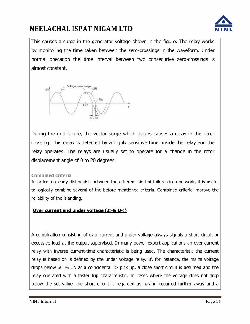
This causes a surge in the generator voltage shown in the figure. The relay works
by monitoring the time taken between the zero-crossings in the waveform. Under
normal operation the time interval between two consecutive zero-crossings is
almost constant.
During the grid failure, the vector surge which occurs causes a delay in the zero-
crossing. This delay is detected by a highly sensitive timer inside the relay and the
relay operates. The relays are usually set to operate for a change in the rotor
displacement angle of 0 to 20 degrees.
Combined criteria
In order to clearly distinguish between the different kind of failures in a network, it is useful
to logically combine several of the before mentioned criteria. Combined criteria improve the
reliability of the islanding.
Over current and under voltage (I>& U<)
A combination consisting of over current and under voltage always signals a short circuit or
excessive load at the output supervised. In many power export applications an over current
relay with inverse current-time characteristic is being used. The characteristic the current
relay is based on is defined by the under voltage relay. If, for instance, the mains voltage
drops below 60 % UN at a coincidental I> pick up, a close short circuit is assumed and the
relay operated with a faster trip characteristic. In cases where the voltage does not drop
below the set value, the short circuit is regarded as having occurred further away and a
NEELACHAL ISPAT NIGAM LTD
NINL Internal Page 17
slower characteristic is used for over current trip. Selective shutdown can then be realized by
a relay closer to the actual fault. As it is the case with all current-time characteristics, this
method is very suitable to disconnect many parallel operating generators selectively from the
mains, preventing the entire network to be without voltage at once. This method cannot be
used for quick islanding at automatic reclosing because it is too slow due to the trip delay of
the current protection. The delay time of the over current detection should not be set too
short because there would be a risk of tripping during switching operations and transients in
the mains.
Directional overcurrent (I> & U<)
By a pure reverse power supervision the operating modes possible are restricted
(e.g.only supply into the public grid) because the current is only allowed to flow in
one direction. If this restriction is not acceptable for a certain application, islanding
can be realized by the combination of current direction and under voltage. To achieve
this, the tripping contacts of both relays are connected in series (interlinked to AND).
During healthy operation the current at the mains coupling point is permitted to flow
in both directions. The directional current relay is set to the effect to trip in direction
of grid if short circuit type currents arise. The under voltage relay trips if the mains
voltage drops under a set threshold. If short circuits occur in the grid, both relays
respond at the same time and the coupling switch is opened. If short circuits occur in
the own system, the current relay does not trip. The necessary disconnections in the
own system are selectively carried out by other protection elements. This method
makes prompt islanding of the CPP possible. Energy is permitted to flow in both
directions. This method is not suitable for islanding during mains failures with an
insignificant drop of the voltage.
[
Requirement of the islanding scheme
NEELACHAL ISPAT NIGAM LTD
NINL Internal Page 18
From the different criteria described above, a reliable islanding scheme should
have all of the following features for islanding
Adjustable multistage under frequency with adjustable time delay
Adjustable multistage over frequency with adjustable time delay
Adjustable rate of change of frequency (df/dt) along with under and over
frequency
Adjustable under voltage with adjustable time delay
Adjustable over voltage with adjustable time delay
Adjustable rate of change of voltage ( dv/dt) along with under and over voltage
Voltage vector shift or vector surge principle
Directional over current and earth fault for faults outside Power Plant zone
Relays to detect Grid disturbances
Previously used electromechanical relays for over voltage and under voltage, earth
fault etc have given way to more reliable and user friendly numerical relays. Unlike
electromechanical relays the over voltage and under voltage condition of the grid are
sensed by single UV/OV relay.
A separate numerical relay is used for sensing rate of change of voltage(dv/dt).
The parameters like frequency, df/dt are monitored by numerical relays .
Numerical relays, with capability to perform mathematical algorithms and to offer very
high accuracy & resolution (settings in terms of 0.01 Hz) are normally used to detect
df/dt.
NEELACHAL ISPAT NIGAM LTD
NINL Internal Page 19
A vector surge relay is useful to detect grid failure condition and also it gives fast response to
grid disturbance. This is an extremely fast acting relay with an operating time of less than
300ms from relay operation to breaker opening.
Grid faults are detected by directional Over current + Directional E/F relays.
Typical relay settings for the islanding scheme
O/V & U/V
O/V – 110% , 1sec.
U/V – 85%, 0.5sec.
Over frequency/Under Frequency
U/F – 47.6Hz, 5sec. & 47.5Hz, 0.5sec
O/F – 52.5Hz, 1sec.
Vector Surge Relays
Vector Surge ()– 6 deg.
Rate of change of frequency -
df/dt – 48Hz & 1Hz/ sec. and 52Hz & 1Hz/ sec.
Rate of change of Voltage -
dv/dt – 75Vs/sec.
POST ISLANDING REQUIREMENTS
Apart from effecting an islanding i.e opening of the incomer breaker of grid, a number
of changes are required to be done in the control system of the CPP to make the
islanding stable.
The following need to be done for the islanding scheme to become successful.

NEELACHAL ISPAT NIGAM LTD
NINL Internal Page 20
a. Immediately after islanding, the islanding signal is given to the governor of the
turbine. This is required to change the governor from load control ( PI control) to
speed control (PD control) mode. Speed control mode is faster than load control
mode. The governor of the generator is made fast acting to take care of a
situation where generation at the time of islanding is more than the connected
load after islanding takes place.
This is also required for the governor of the TG to respond to any load change
during the islanding condition.
b. Though tripping of a generator due to fault does not create a major disturbance in
the power system during synchronized operation, it seriously handicaps the ability
of the CPP to run in islanding mode. If the islanding load of the CPP is more than
the available generation of the CPP, then load shedding is to be done to bring the
islanding load lower than the generating capacity. A fast acting load management
scheme is put in place for stable islanding to take place. The excess load is
switched off by a suitable load-shedding scheme to make the islanding of the
generator stable. The frequency of the power system is monitored to shed loads in
staggered manner.
c. In case of severe voltage disturbance the drives of the captive power plant also
trip leading to unstable condition after islanding. Suitable schemes are put in place
to take care of such type situation.
d. Usually the Automatic Voltage Regulators of the generators operate in power
factor control mode. After islanding, this is to be made off and the MVAR
generation is matched with the requirement of the plant. Otherwise it will lead to
under voltage/over voltage condition.
During the period of islanding, CPPs have to put a strict restriction on starting of bigger drives as that can destabilize the power system network leading to total power failure.