power generation managing materials clean water …
TRANSCRIPT

INSIGHTA publication of Intergraph® Process, Power & Marine // Issue 31 // Quarter 2, 2012
POWER GENERATIONPLANT EFFICIENCY
MANAGING MATERIALSFOR MEGA-PROJECTS
CLEAN WATER wITh RENEwAbLE ENERGY
Focus on
OwNerOperaTOrS»Asset Management »Plant Instrumentation»CAD Productivity
INduSTry
NewS
Focus on Laser scanning»Fenstermaker »MAJA Consulting Group

Quarter 2, 2012 » www.intergraph.com l INSIGHT 1
Features2 Letter from the editor: Trust
Focus on Owner Operators4 Leveraging the Virtual Asset
6 View from the top: Exceptional Growth for the O/O Business
Industry News 8 Keeping Up to Speed: The Role of Asset Management in O&M12 Tuning Plant Instruments for Smooth Operators16 CAD Productivity for Owner Operators
Focus on Laser Scanning20 Integrating Laser Scanning and 3D Design
Customer Viewpoints 22 MaJa Consulting Group: Intelligent Laser Technology 24 Fenstermaker: Innovative Laser Scanning Workflows
Industry News 26 Clash-free Confidence
Customer Viewpoints30 empresarios agrupados: Powering Up Productivity
32 temco: No Limits34 Chiyoda: Effective Materials Management for Mega-projects36 aCCIONa agua: Clean Drinking Water Produced with Renewable Energy
38 Iet: Quality Design for Turnkey Projects
departments40 at a Glance42 What’s Next46 Industry Outlook: Making the Case for Change
contents
I s su e 3 1 / Q uA RT e R 2 , 2 0 1 2
CuSTOMer VIewpOINTS Page 30
24
8

2 INSIGHT l Issue 31 » Quarter 2, 2012
L e T T e R F ROM T H e e DI TOR
Trust Trust is highly valued, yet it cannot be bought or sold. It must be earned over the test-
ing of the years. Intergraph solutions like SmartPlant Enterprise for Owner Operators have earned the trust of many customers by working to solve their complex and varied workflows around the world. When I first started working for Intergraph in 2001, Owner Operators comprised less than 10 percent of our total revenue. So it’s both humbling and gratifying to see that 10 years later, Owner Operators comprised 27 percent of our total revenue.
We want to grow, and that means Intergraph is still focused on further earning your trust. The owners’ side of our business is expanding rapidly thanks to our focus on capital project productivity and effective management of technical asset information through-out the life cycle. This issue of Insight brings you a spotlight on Owner Operators and how they are using our solutions to succeed.
A strongly related focus of this issue is laser scanning technology. With the Hexagon acquisition of Intergraph in 2010, we now have a close relationship with all of the Hexagon companies, including Leica Geosystems. Our scanning solutions have always been open and interoperable across the industry, but now with our partnership with Leica, we can offer an even broader integration with Leica and expanded use of laser scanning technologies in the future. Come to Hexagon 2012 and see for yourself. I guarantee you’ll leave with a new perspective on the future of Intergraph technology.
Everyone at PP&M knows Gerhard’s Rule No. 1: “Never ever let a customer down.” Customers have come to trust us, making us the market leader today. Thank you for that trust. We are here for the long haul and excited to help you in your journey.
I look forward to meeting with you at Hexagon 2012 in Las Vegas and building the future together.
Patrick HolcombInsight Editor
Executive Vice President, Global Business Development
Intergraph Process, Power & Marine
Trust has to be earned, and should come only after the passage of time.
Arthur Ashe“
“
change is the only constant
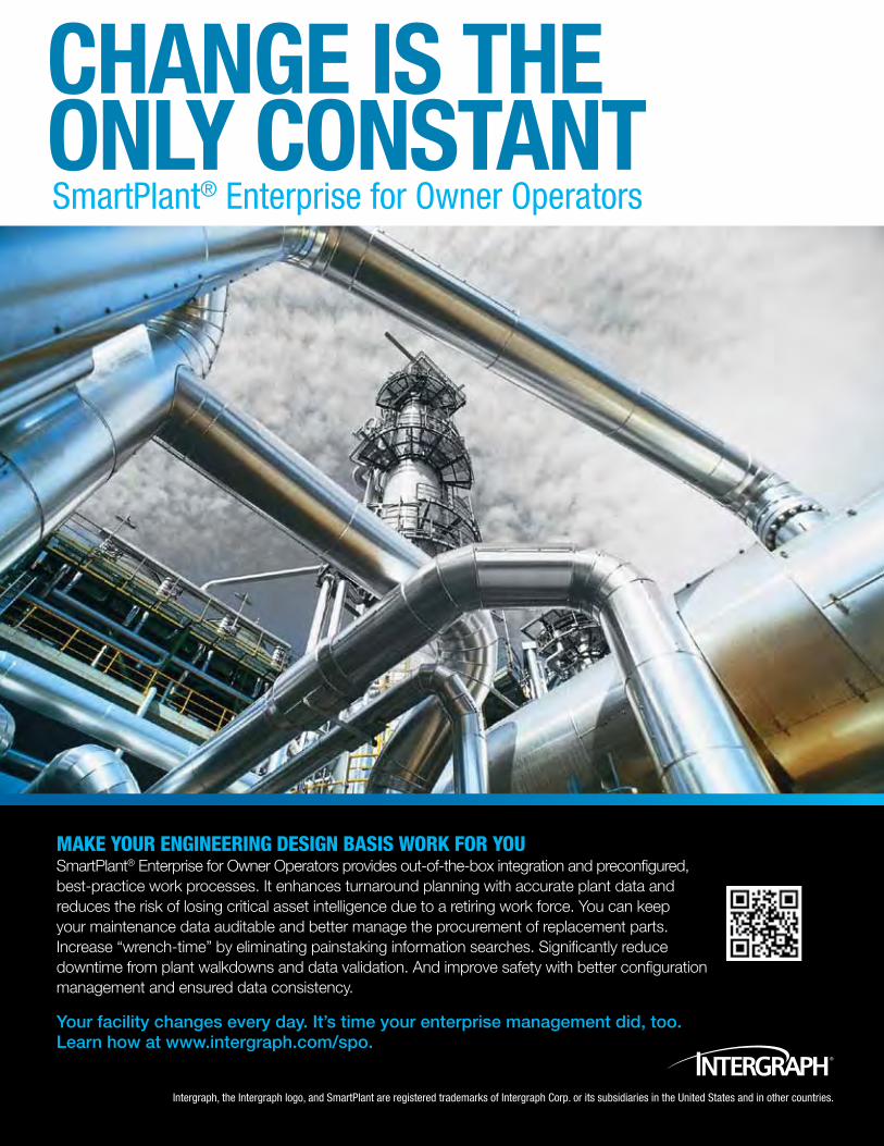
Make your engineering design basis work for you SmartPlant® Enterprise for Owner Operators provides out-of-the-box integration and preconfigured, best-practice work processes. It enhances turnaround planning with accurate plant data and reduces the risk of losing critical asset intelligence due to a retiring work force. You can keep your maintenance data auditable and better manage the procurement of replacement parts. Increase “wrench-time” by eliminating painstaking information searches. Significantly reduce downtime from plant walkdowns and data validation. And improve safety with better configuration management and ensured data consistency.
Your facility changes every day. It’s time your enterprise management did, too. Learn how at www.intergraph.com/spo.
Intergraph, the Intergraph logo, and SmartPlant are registered trademarks of Intergraph Corp. or its subsidiaries in the United States and in other countries.
SmartPlant® Enterprise for Owner Operators

Leveraging the Virtual Asset
Owner OperatOrs face a number of distinct challenges. The Operations & Main-tenance group wants to minimize unplanned downtime, reduce OPEX, minimize health and safety risks, and achieve demonstrable compliance. For Commissioning, Startup & Handover, key objectives are to accelerate operational readiness and maximize virtual asset quality and completeness for O&M. Meanwhile, the Capital Projects group attempts to re-duce CAPEX and shorten project schedules. Meeting shareholders’ profitability targets can be difficult when confronted with these business needs.
According to the ARC Advisory Group, “Achieving plant owner operator profitability goals requires a different model of asset life cycle management and an information manage-ment infrastructure that enables effective interoperability among all stakeholders.”
Plant knowledge represents a virtual asset. Today’s owner operators are looking for ways to better leverage this virtual engineering information asset.
SmartPlant Enterprise for Owner Operators is a dedicated engineering solution for safely building, operating and maintaining plants and offshore platforms. Intergraph enables plant operators and ship and offshore platform builders to increase productivity and accelerate projects by reducing capital and operating expenses to gain a competitive edge.
Read on to see how Intergraph’s solutions are helping to enable huge advances in pro-ductivity and profitability. Intergraph makes it easier for users to manage the continuously changing engineering design basis. »
» FOCuS ON « OWNER OPERATORS
4 INSIGHT l Issue 31 » Quarter 2, 2012

Quarter 2, 2012 » www.intergraph.com l INSIGHT 5
VIEW FROM THE TOP: Exceptional Growth 6 INDUSTRY NEWS: Keeping Up to Speed 8 Smooth Operators 12 CAD Productivity 16

Intergraph has built a strong tradition as an industry leader worldwide. Owner op-erators are a central part of Intergraph’s growth strategy. Insight recently met with Gerhard Sallinger, president of Intergraph Process, Power & Marine, to discuss how Intergraph’s solutions are meeting the needs of more owner operators. Insight: How has Intergraph’s share of the owner operator market grown in relation to the growth of its owner operator solutions?
Gerhard sallinger: Over the last cou-ple of years, we have steadily grown the owner share of our business compared to the EPC side. Approximately 27 percent of our business in 2011 was from owners, and I believe we are still at a relatively early stage in this respect.
What is new and what is leading to the exceptional growth we have in the owner space is the management of technical data. Owners in the past were looking for docu-ment management. The most they wanted was just to manage that sort of data. For many years, there have been vendors in the market that develop and market docu-ment management systems. Intergraph could do that as well, but our system is not focused on document management.
Our business is more about managing the underlying data behind those docu-ments. Five years ago, most people didn’t care or didn’t understand the value of that data, but this has changed. To a large ex-tent, it has changed because of us.
We are basically evangelizing the in-
from the top
VIew FrOM THe TOp » I n D u s T Ry L e A De R G A I n s G RO u n D
Exceptional Growth for the Owner Operator Business
dustry to spread the word that, “It’s not only the document, but the data behind it that is the value.” Thankfully, more com-panies understand that and see the value.
Intergraph is now the leading company in data management for the industry. So what we see is that SmartPlant Founda-tion, and specifically SmartPlant Enter-prise for Owner Operators – which is built on top of SmartPlant Foundation – is very successful, and many owners are jumping on it and adopting it.
A major customer has selected us as its partner for managing the plant data of new plants it builds – and it builds a lot of new plants. So we went through an imple-mentation phase and pilot phase, and last year the customer approved SmartPlant Enterprise for Owner Operators as ro-bust and ready to go. It has already rolled it out to five new plants it is building. The plan for this year is adding another seven plants and all of those plants will have the solution implemented and likely managed on a global network.
ConocoPhillips is using our data man-agement solutions on a couple of projects. We are working hard to find and extend to a number of other large oil and gas com-panies worldwide. The list is long and it’s growing, including Adnoc, ENI, Petro-bras, Petronas, Repsol and Saudi Aramco.
The growth potential here is tremen-dous and this opens doors for us in many of those owners’ companies where we had very little footprint in the past. The owner operator business in the next couple of years will easily double or triple, so I fore-see the owners’ share of our business being in the 30 percent to 35 percent range – a much bigger total than we already have.
Speaking of the future, what’s going to happen in the high-growth BRIC countries – Brazil, Russia, India and China?
Gs: Our growth rate in China for 2011 was 53 percent. Brazil was 25 percent. For Russia, the Middle East, and India, our
6 INSIGHT l Issue 31 » Quarter 2, 2012
It’s not only the document, but the data behind it that is the value.
“
“

growth rate in all of those regions was in the 20 percent-plus range. I think we are doing quite well in those growth regions.
And the same potential growth for owners is true here as well. The growth rate in the BRIC countries is much higher than in the developed part of the world. This trend will continue. The percentage of revenue coming from those countries will increase over the next couple of years.
The largest percentage of our growth is indeed coming from the BRIC regions as well as the owners business. The two most dynamic products we have are Smart-Plant Foundation/SmartPlant Enterprise for Owner Operators and the new Smart 3D products for the onshore and offshore industries. So looking at future growth, I would summarize it as owners, BRIC and the new Smart 3D products as our three most dynamic areas.
Intergraph has diversified its solutions portfolio and the markets it serves over the years. Now that we are working with other Hexagon companies, such as Leica Geosystems, how will this help us better serve our customers?
Gs: With Leica for laser scanning, the technology is there to make this quite at-tractive, because you need to combine your point clouds with the CAD models. We already have quite a good solution for this and in the next couple of months there will be a lot of activities going on. This is one central element of our Hexagon 2012
By JA nA M I L L e R
message in Las Vegas.We have shown this technology
to our sales force and it is compelling. The industry is picking up on it, because for brownfield, it is a very attractive meth-od to acquire existing plant information and data in an electronic format and do revamps and expansions.
Just look at our competitors for a good indicator on how hot a technology or in-dustry is, because they follow us with some delay over time. One has recently purchased a solution that is basically a competitor to us and Leica. Our competi-tors are like bloodhounds in a way. They see where the trends are going and what we are doing and they follow. The same holds true for the data management and for the owner operator space. It’s also true for integration. It just proves that we are leading the industry.
Laser scanning is certainly an inter-esting market. It’s a bit difficult for me to give a serious forecast in terms of revenue numbers. But it will definitely be a few million dollars this year, and in two to three years from now, it will be a good and significant piece of our business.
Intergraph acquired COADE in 2010. How has this acquisition helped Intergraph to grow?
Gs: Our Intergraph CADWorx® & Analysis group is doing quite well with its products CAESAR II® for pipe stress anal-ysis, TANK™ for tank analysis, PV Elite®
for pressure vessel analysis and CADWorx for plant design. CADWorx offers 3D de-sign based on AutoCAD®, and in its league it’s quite powerful. CADWorx is good for ease of use and small- to mid-size projects, and we see it gaining ground.
The big growth potential for this prod-uct is outside North America, because to-day 80 percent of the CADWorx revenue is coming from the United States and Cana-da. There is zero reason why this shouldn’t be as successful in Europe and Asia as it is in North America. I see a potential to triple or quadruple the CADWorx revenue we have today in the next three to four years.
So we need to make sure that we have the proper focus in Asia and Europe. We did that to a good extent in 2011, so we are now ready to bring it up a few notches in those two regions. We have the people and the resources to make this happen and make our customers successful. ■
Jana Miller is editorial director of Insight and is based in Huntsville, Alabama, U.S.
www.intergraph.com/ppm
Quarter 2, 2012 » www.intergraph.com l INSIGHT 7

8 INSIGHT l Issue 31 » Quarter 2, 2012
n a quickly changing world, rapid technology devel-opments have accelerated the aging of plants to levels that challenge the feasibility of any project. “Getting it right” from the very early stages of plant design has become critical to ensure smooth and effective plant operation and plant maintenance. The engineering design basis and plant asset integrity play an increas-
ingly important role in ensuring safe, effective and sustainable operations.
Owner operators are recognizing the need for plant life cycle information management strategies and supporting technologies to ensure smooth handover and startup of operations and to avoid time-consuming, costly and risky plant maintenance practices.
Certain plant design criteria are highly relevant for the op-timization of plant maintenance. Plant maintenance revolves around reliability and safety, and therefore, understanding the design concepts that are critically linked to these variables will enable engineers and technicians to implement effective mainte-nance practices across multiple plant assets and operations.
Intergraph manages, analyzes and closely monitors these cri-teria to ensure that the work processes provided by SmartPlant Enterprise for Owner Operators throughout both the capital ex-penditure and operational expenditure phases of the plant life cy-cle optimally assist owner operators. Equivalent SmartPlant En-terprise solutions are available for contractors to help them build the engineering design basis and execute the project effectively.
Plant asset managementThe “virtual plant” assets and components (often designed
and built by EPC contractors), all the in-plant documentation, as well as the IT systems, must be consistent with the current physi-cal state of the plant in operation. When this is not the case, plant documentation cannot be trusted and walkdowns are constantly required to verify the true state of the plant, wasting effort and unnecessarily exposing workers to trips, slips and falls. During plant incidents where rapid decisions need to be undertaken,
INduSTry NewS » H y DRO C A R B On e nG I n e e R I nG
Keeping Up to SpeedBy A DR IA n PA R k
» The role of asset management in safe, effective and sustainable plant operations and maintenance
there may be no time to perform field verification, resulting in plant workers making decisions based on unreliable information, thus potentially jeopardizing personnel, the plant and surround-ing environment.
Managing plant reliability requires a broader view toward how critical plant assets and resources are deployed and lever-aged. From early in the design phase, plant owners are now imple-menting complete plant asset management (PAM) systems and requiring early handover during project developments from con-tractors. This enables operations personnel to:
• Assess the risk of production outages• Schedule and plan future maintenance activities• Perform spare part evaluation• Prepare training materials for operations staffThe PAM system must provide consistent, accurate and high-
quality information, which is critical to manage the engineering design basis and documentation for the plant. The PAM system also plays an important role in coordinating all the organizations involved with an asset (disciplines, contractors, owner operator organizational units, suppliers) as well as planning operation and maintenance activities.
Asset integrity, supply chain management and regulatory compliance are directly linked to plant asset information man-agement. Managing relationships between tags, models, assets (serial equipment) and manufacturers is very important for plant owners. If these relationships can be established during a green-field/brownfield project, they provide an excellent basis for estab-lishing the plant asset structure required in the plant’s computer-ized maintenance management system (CMMS).
Ensuring cross references of all data to the existing materi-al catalog in SAP® MM or another catalog provides a basis for achieving maintenance, repairs and operations (MRO) inventory reduction and normalization of equipment documentation.
The PAM system and CMMS are implemented to support:• Maintenance scheduling• Turnaround planning• Managing change on the operating plant• Troubleshooting• Inventory management and purchasingThe value of these systems is further enhanced when integrat-
This article is reprinted with permission from Hydrocarbon Engineering magazine.

ed with automation, production scheduling and manufacturing systems.
Scope of interoperabilityInteroperability is the ability to show and share data across
multiple IT systems seamlessly. Intergraph’s SmartPlant Enter-prise for Owner Operators provides selected out-of-the-box in-tegrations and is capable of rapid integration with third-party systems, including:
• Providing seamless access through a common Web portal to information from the engineering design basis (including intelligent piping and instrument diagrams, 3D models or laser scans) with systems such as CMMS, DCS and content management systems
• Handoff of approved changes in SmartPlant Enterprise for Owner Operators to a CMMS as notifications against CMMS locations for maintenance to undertake work
• Automated synchronization of change in the engineering design basis and CMMS to ensure both systems are con-sistently up to date with changes in the plant configuration
Management of changeMaintaining the dynamic engineering design basis in line
with plant modifications during operations is a safety-critical, de-manding activity. Plant design and the configuration of the plant are susceptible to changes (approval cycle, compliance, informa-tion feedback and cross notification of engineering and mainte-nance data), which can have a serious impact on plant operations
if not tracked, recorded and shared appropriately. Ensuring the accuracy of essential plant engineering, maintenance and opera-tions information is vital to safe, efficient plant operations.
Intergraph’s management of change (MOC) process provides rigorous MOC of engineering information with full traceability and audit trail to provide demonstrable regulatory compliance. All change requests can be related to affected tags, documents and parts of the plant breakdown structure. This enables the identifi-cation of other changes being considered or already approved that affect the same items and analysis of whether there are synergies or conflicts between the various change requests that should be taken into account.
The preconfigured MOC process includes the review, autho-rization by a plant change board, design and approval of changes by engineering in the engineering design basis, and optionally the notification of maintenance to perform changes by creating notification records in the plant maintenance system. Approved changes not handed off to maintenance can remain as candidates for a subsequent turnaround.
Continued maintenance integrityData and data interrelationships are key to the plant’s asset
configuration and management. Ensuring that changes to the as-built plant design basis are consistently and rapidly reflected in the CMMS is a challenge for all operating plants. Most owner operators rely on manual processes to ensure that changes in the plant design are reflected in the CMMS, but this is often a process that is prone to errors or is not undertaken consistently. The con-
Quarter 2, 2012 » www.intergraph.com l INSIGHT 9

sequences can include:• Application of incorrect maintenance plans to equipment• Equipment not being maintained or inspected at all• Procurement of incorrect replacement equipment and partsThe automated synchronization of changes in the engineering
design basis with the CMMS offers a much more effective and re-liable approach to ensure that the CMMS is kept up to date.
SmartPlant Enterprise for Owner Operators provides the syn-chronization of data between the engineering design basis and the CMMS and is, for example, available for SAP PM. Where tags are created, updated or terminated in the engineering design basis, SmartPlant Enterprise for Owner Operators will trigger an au-tomated creation or update of the corresponding functional lo-cation in the plant maintenance system. In practice, not all tags will be sent to SAP PM as functional locations; each owner has its own rules as to which tag types at what life cycle states should be transferred to SAP. For example, most owners do not send cables or signals to SAP PM. Similarly, most owners do not send tags to SAP when they are first reserved, but rather only when they have reached a planned or as-built status. This is to avoid the creation of redundant functional locations in the CMMS.
The SmartPlant Enterprise for Owner Operators process in-cludes flexible configuration rules for which tags are sent to the CMMS at different life cycle statuses. Synchronizing information between the engineering design basis and maintenance systems has major synergy benefits to critical operational processes.
Verification of plant asset dataHigh-quality plant asset information is a prerequisite for safe,
effective and sustainable operations. But verifying the quality of data received by operations from contractors and suppliers or to check the quality of data in legacy operations systems is a chal-lenge due to the millions of records that need to be checked and
the complexity of verifying if the data is complete, correct and consistent.
To meet these challenges, Intergraph provides its Validation, Transformation and Loading (VTL) tool to assist contractors and owners who wish to check the quality of plant asset data. This tool may be used to:
• Monitor the progress of plant engineering deliverables dur-ing capital expenditure projects
• Monitor the quality of final deliverables• Check data in legacy systems as part of a data migration
processIntergraph’s VTL solution enables users to validate data from
multiple contractors, suppliers or legacy data systems. Data is imported into a staging area where it is held in “quarantine” and subject to verification against a wide range of business rule types that are available, such as checking:
• Syntax of names is correct• Mandatory information has been completed• Relationships are valid• Fields with a limited range of valid values such as EX Code
and IP Class are correctSubsequent validation reports can be used to report data back
to contractors or suppliers that must be corrected or as a basis for correction. Details of all validation rules applied and results are held for traceability.
Validated data may be exported to target systems and the whole process of import, validation, export and target system loading may be automated end to end.
SafetyA safety issue in plant maintenance is often related to poor
management of change. Many risky or dangerous events can be attributed to a change in plant assets or a wrong decision based on incorrect or outdated data that can be prevented with good MOC procedures. Plant safety requires the accuracy and ready-to-use availability of plant asset data, operating manuals and procedures, because plant configurations are susceptible to change as a result of revamp projects, turnarounds or maintenance modifications.
The maintenance of as-built 3D models can play an important role in plant safety. Where models are up to date and can be relied upon, they can:
• Reduce the need for plant walkdowns and associated risks related to trips, slips and falls
• Become an important interactive training tool related to the familiarization of staff with the plant and to refresh knowledge of escape routes
• Simulate complex procedures such as the dismantling and replacement of equipment
With the advent of intelligent, rules-driven 3D modeling in
» k e e P I n G u P TO sP e e D
10 INSIGHT l Issue 31 » Quarter 2, 2012

www.intergraph.com/ppm/spo
SmartPlant 3D and SmartMarine® 3D, safety rules can be built into the model to ensure compliance, such as to highlight where EX rating of electrically powered equipment does not comply with the area classification of that location on the plant.
Lock out and tag out (LOTO) is the process of isolating equip-ment so that it may be worked on in a safe manner. The process of planning isolations consumes considerable time of some of the most experienced staff on the plant and is often a process still dominated by paper-based systems and is prone to potential er-rors that can have major safety implications. The availability of integrated, intelligent schematic design tools, 3D models and information management repositories enables new solutions to be designed to assist in planning and executing isolations. This approach will result in better planning, safer execution and im-proved overview and supervision of isolations during the main-tenance of plants.
The efforts of plant process safety teams in performing haz-ard and operability (HAZOP) analyses are critical elements to ensuring plant safety. The effectiveness of these teams is heav-ily dependent upon their ability to access the safety knowledge of their most experienced engineers, operations staff and safety experts.
Intergraph solutions enable companies to capture their accu-mulated safety knowledge in a rules-based knowledge repository. By largely automating hazard identification, the application can cut the time and cost of HAZOP studies in half.
HAZOP analysis, accessible through a portal-based inter-face, uses intelligent process and instrumentation diagrams from the engineering data warehouse to automatically trace hazard and operability issues. This capability enables rapid updating of HAZOP reports as plant changes occur.
Responding to incidents fasterUltimately, managing plant asset data and plant maintenance
is directly linked to faster risk assessment and better decision- making. Providing the most appropriate response to incidents is achieved by rapidly collecting all the necessary information and by better controlling the plant systems, assets and personnel.
Seconds count when responding to plant incidents. Providing plant floor workers and engineers with quick and easy access to essential plant engineering information, together with data from other operations systems such as DCS and maintenance systems, can make a major difference in supporting critical decision-mak-ing processes.
In practiceMany of these factors were at the core of the collaboration
between the engineering company Grenland Group and Inter-graph when designing the revamp and modernization of oil and
gas processing plants in the North Sea. Design for durability and optimal maintenance were the major requirements set by the O/O, who was facing mounting pressure to increase production.
The modernization of the existing plant required redesign of certain processes, information for prefabrication, revamped design and maintenance optimization. Data collection, instru-mentation and a central repository to validate data from multiple contractors, suppliers and legacy data were major challenges in the project. Intergraph adopted a partnership approach that combined Intergraph’s engineering and operating software with complementary software from other superior industry vendors that respond to the demands of EPCs for holistic and truly effec-tive solutions for the life of the plant. ■
Adrian Park serves as global executive director of Owner Operator solutions at Intergraph and is based in Stavanger, Norway.
Quarter 2, 2012 » www.intergraph.com l INSIGHT 11

12 INSIGHT l Issue 29 » Quarter 2, 2011

ncreasingly, larger and complex proj-ects, whether greenfield projects or brownfield projects, are testing the boundaries and the performance of process and control systems. The pres-sure to deliver projects faster and with a more efficient design is mounting.
As a result, design and operation engineers have turned their eyes to instrumentation and control, as the discipline affects all areas of plant operation and can profoundly impact plant reliability, effi-ciency and operations and maintenance costs. Im-proving the reliability of existing instrumentation and control systems and their components enables plant operators to make informed decisions as early as possible in the workflow, thus avoiding costly re-work, or worse, reordering expensive plant compo-nents or facing production shutdowns.
Engineering companies and plant owners are always in search of engineering solutions that best fit their needs in terms of improving the business and lowering the risk of project execution and plant operations. The basics of engineering have not changed significantly: an engineer must still specify instruments, create datasheets, connect the wiring, etc. However, there have been changes in the busi-ness drivers (schedule, cost, project size and time to market) that call for a more holistic approach and more efficient management of the engineering data.
Control system engineering is a key component for plant uptime, quality production, flexibility, plant reliability and operational cost. Therefore, owners are looking to keep their control systems up to date and in many cases update them to newer
technology to meet increasing challenges and to achieve their goals. Installations are growing larger and more complex, and many are being built under substantial time pressure to respond to the growing demand for energy in emerging countries, such as Brazil, Russia, India and China.
From an engineering and project execution per-spective, such large projects are being executed by an increasing number of engineering, procurement and construction companies (EPCs), which poses challenges in terms of keeping the design and the control system consistent with the owner’s prac-tices and requirements.
Principles for improvementEngineering developments focus on driving
the industry to more intelligent integrated solu-tions that help respond to new challenges. Within control system engineering, three principles are shaping today’s improvements:
• rule-driven design – A set of rules are de-livered and customized, enabling owners to consistently determine standards and best practices. This ensures consistency across contractors and along the project and enables faster and more accurate decision-making.
• relationship engineering – Plant assets, control systems and different teams are interlinked. Relationships between them and the entire connectivity model help users to understand and operate the plant as a whole and to reproduce changes simultaneously across all plant components.
INduSTry NewS » H y DRO C A R B On e nG I n e e R I nG
Tuning Plant Instruments for Smooth Operators
» Control system engineering improves the safe, efficient and economical operation of a plant
Reprinted with permission from Hydrocarbon Engineering magazine.
By F R A n k J O OP
Quarter 2, 2012 » www.intergraph.com l INSIGHT 13

» T u n I n G P L A n T I n s T Ru M e n T s F OR sM O OT H OP e R ATOR s
• Deliverables are an exact representation (view) of the design – Deliverables are created as a report from the in-strumentation database. This is primarily a productivity ca-pability. But the deliverable’s depiction of the design’s exact intention is even more important for engineers and owners.
Consistency and accuracyInstallation and commissioning of a control system is a com-
plex task, with several stakeholders involved, including owners, vendors, package vendors, engineering contractors and the op-erational team. This is the case in both greenfield and brownfield project design. Ensuring that the design and installation process is as efficient as possible is key to success. Rule-driven design of control system engineering software would enable an early set of consistent indicators and instruments, whose output and per-formance can easily be monitored by control and maintenance teams. Engineers can be assured that the design is in compliance with the client’s best practices and local engineering standards. Early rule design also has an economic impact: according to gen-eral practice standards, an error found during the design phase costs the owner only US$1; while the same error detected during the process phase costs US$10; and found during the construction phase, that error would cost the company US$1,000.
Another fundamental aspect of control system engineering involves relationships. Control system design is typically a disci-pline that creates deliverables representing different views of the same instrument. For example, an instrument can be shown on a loop diagram, wiring diagram, specification sheet or installation drawing. If a change is introduced, the challenge is to generate all the different deliverables in a consistent and accurate manner and as quickly as possible. The deliverables and the relationships between them need to be generated from a single source, ensur-ing accuracy, consistency and optimal upgrading of changes. This output relationship and its upgrading will have a tremendous impact in plant operations, maintenance and ultimately perfor-mance.
One of the most advanced rule-driven and relationship tools in the market is Intergraph SmartPlant Instrumentation. The software provides a single source of instrumentation informa-tion that can be easily accessed and updated and that is consistent across the different instrument tasks and deliverables.
Generating integrated instrumentationControl system engineering is not an isolated discipline. It has
multiple “connections” with other disciplines and suppliers. Con-trol system engineering plays a fundamental role in integrating other disciplines’ outputs and ensuring that the project is execut-ed in the most efficient way.
The piping and instrumentation diagram (P&ID) represents both the process and the control functions in a plant. These func-
tions are captured and expanded into the physical components that make up these functions: a process achieved through data integration and rules application. For instance, flow measurement and regulation will expand to incorporate:
• Flow element• Transmitter• Input/output• Valve• Current to pressure converter• Hundreds of loopsAll the instrument and process data needs to be generated into
specification sheets, one of the first and most important deliver-ables in a project. Although specification sheets have been gener-ated for years, it is possible to create these more efficiently by in-creasing their quality and creating them faster. The specification sheets in advanced control system engineering software can help select lists to quickly and consistently enter data. In addition, the software manages data in a more intelligent way, by highlighting a specific field, depending on the duty of the instruments, to ensure that essential fields are entered for each specific instrument.
Specification sheets can then be sent to the vendors for part selection and final calculations. The vendor can send the dimen-sional data for the instrument (for example, valves) to a 3D solu-tion (for example, SmartPlant 3D). Based on those dimensions, it is possible to drive the 3D parametric engine to model the com-ponent before the piping engineer places it directly into the line with the correct flange-to-flange dimensioning. This ensures that the isometrics and the overall dimensions for the interface, access and maintenance are correct.
Automation vendors play an increasingly active role in project execution. Therefore, interfaces with their systems are essential, such as configuring the distributed control system (DCS) and as-sociated wiring. Automation vendors like Emerson are also mov-ing forward with innovative systems such as CHARMS, which is a flexible single-strip marshaling capability. Intelligent software such as SmartPlant Instrumentation can work closely with ven-dors to support innovation in engineering solutions. SmartPlant Instrumentation offers a simplified assembly of instrument con-struction and commissioning packages during commissioning, and enables accurate, up-to-date test status for planning and re-porting.
Treasuring as-built documentsThe future drivers of control system upgrading projects will
focus on lowering the OPEX cost, increasing product quality and raising plant efficiency and productivity. Achieving these objec-tives through upgrading or expanding plants depends very much on the available plant data and as-built documents. In many brownfield projects (plant revamps, upgrading of existing plants), the as-built documents are out of date, are available only in paper
14 INSIGHT l Issue 31 » Quarter 2, 2012

Frank Joop serves as executive director of business development for Engineering & Schematics at Intergraph Process, Power & Marine. He is based in Huntsville, Alabama, U.S.
sheets or are even absent or lost. One possible solution is to regenerate all data by laser scan-
ning the existing plant to document the existing installations, their location and current state, which is essential in the case of the new system being fieldbus-based (length of cables and num-ber of instruments on a spur). The method of laser scanning can be improved by tagging plant items, including instruments and junction boxes. This will help to lower the cost and reduce the time needed to be back to full production.
The promotion of rapid input of as-built data provides a plat-form for safe, compliant startup and operations, as well as better scheduling of plant shutdowns. Accurate data, current data and a long-range view of instrument behavior enable multi-project ex-ecution and add multiple process cases for production scenarios.
In the case of greenfield projects, starting afresh is a major ad-vantage. Although no two projects are identical, lessons learned from other experiences can be used. Setting up the engineering rules and generating automated data from the very beginning of-fer the ability to continuously improve processes and operations.
All data created for the design and construction of a plant is used during operations. The old days of delivering a stack of pa-per documents are over. It is now possible to hand over all data from engineering to operations in digital format. Intergraph SmartPlant Enterprise for Owner Operators, which is integrated with SmartPlant Instrumentation, can store and manage primary data, in addition to data and documentation from other parties. The software creates relationships, allowing operational teams to quickly recall specific vendor documents, discipline documents or control system documents. In addition, integration can be achieved with enterprise resource planning (ERP) systems such as SAP to show related maintenance records.
Data sharing and monitoringSmartPlant Instrumentation also offers operational capa-
bilities, such as calibration with a link to Fluke, to capture the original calibration data. Once calibration of instrumentation, data verification and electrical design are under control, the en-gineering scope and process methodology will change. However, changes will no longer pose a threat, as operation and mainte-nance engineers know how and where the changes have occurred.
Intelligent control system engineering software also offers broader capabilities in worksharing, ensuring that multiple disci-plines, contractors or vendor companies can share all the instru-mentation data and instantly access any information updates. A growing number of owner operators have their production plants in one country and host their instrumentation database in an-other country, while many different EPCs work in the project in different units, all connected to the same repository.
Last but not least, control system engineering plays a key role in safety. Automated solutions improve the hazard and operabil-
ity studies, and in many cases, the risk detection and fast response responsibilities are performed by control systems. Recommended integrated safety level factors can be created in SmartPlant Pro-cess Safety before being conveyed into SmartPlant Instrumenta-tion. Based on this information, the software can design the right system with the right protection and backup layers. The system also enables users to quickly perform HAZOP analysis during the design process and operations and to automatically create cause and consequence reports. ■
www.intergraph.com/go/es
Quarter 2, 2012 » www.intergraph.com l INSIGHT 15

Reprinted with permission from Chemie Technik.
he use of 3D plant design tools is a “no-brainer” for most medium- and large-sized engineering companies. The busi-ness benefits are so great that it doesn’t make sense to perform plant design without it. Today’s 3D plant design tools speed the design process and make de-sign quality better and safer.
The world’s largest EPCs and O/Os choose Intergraph’s state-of-the-art, high-tech solutions for me-dium to large and mega-sized capital projects. Recently, Inter-graph also began serving smaller and less complex projects with its AutoCAD-based CADWorx solution.
With CADWorx, Intergraph serves an entirely different segment of the plant design world, such as engineering companies that ex-ecute smaller projects like revamps, turnarounds and extensions
of existing plants with brownfield projects. Companies that build package units, skid-mounted installations or equipment like ves-sels, pumps or compressors can also take advantage of CADWorx. The largest differentiator between small projects and large capital projects is the lack of time or budget for training, admin-istration and maintenance costs in small project execution. This is a significant factor when using enterprise plant design software that is applied in large capital projects.
Information is an assetOwner operators are primarily focused on their core business,
which is “cooking oil,” “baking plastic” or “pressing pills.” Some of the bigger players in the market have engineering departments, but many other owners don’t and rely on EPC services for their engineering disciplines. Even if they do, often the management of the information and the management of the project are per-formed by different departments with different levels of integra-tion and coordination.
In many cases, the plant information managed by the owner is a dump flat collection of documents and drawings carrying different naming conventions and different plant breakdown structures, all stored in different formats. Symbols used in the drawings might look the same when printed on paper, but a closer investigation will soon prove that there have been many different methods used in creating a particular symbol.
Numbers of AutoCAD and MicroStation drawings are the re-sult of different EPCs and other users changing the drawings over the course of many years. Without some standard engineering and information processes in place, along with good work pro-cedures ensuring that the information is correct and according to standard, running a plant at full productivity can be a challenge.
There is another issue that makes plants run a little less smoothly. Only a few owners keep the original design of the plant up to date, and even less plant owners have an accurate 3D model of the plant. In the past, it was very expensive to keep a 3D model up-dated for small projects, maintenance and operations. The software was very expensive to maintain. But this is not the case any longer. Costs are much lower and 3D has never been this easy to use.
CAD Productivity for Owner OperatorsBy P e T e R vA n De R W e I J De
» Scalability and integration boost plant productivity throughout the life cycle
INduSTry NewS » C H e M I e T e C H n I k
16 INSIGHT l Issue 31 » Quarter 2, 2012

Meeting business driversHow can the implementation of CAD and CAE help owners
achieve an easy-to-run and productive plant? To answer this, take a look at the most important business drivers of the owner:
• Time-to-market – Keeping the plant running for as long as possible, producing as much as possible
• Saving cost during maintenance, operations and projects• Quality of engineering data, outputs and deliverablesAll three of these business drivers must also comply with gov-
ernment regulations for health, safety and the environment.
Time-to-marketA faster time-to-market generates considerable return on in-
vestment. CAD tools in the market have focused on shortening the maintenance repair cycle, enabling a plant to restart earlier. This is done through standardization, which is also instrumental for increasing engineering data quality and in saving costs during maintenance and operations.
QualityThe basis for quality lies in bringing the company’s standard
into the CAD software, such as:• Pipe specifications and catalogs• Symbol libraries• Naming conventions• Drawing templatesThis way, companies do not have to reinvent or re-enter their
standards again and again. The use of company standards can be enforced as mandatory and made available to everyone and for every project.
Intelligent P&IDsAnother key factor to improve productivity is intelligent P&ID
generation. The P&ID is one of the most important documents for an owner. It gives a basic overview of most objects from different disciplines in the plant:
• Equipment• Piping• Instrumentation• ElectricalThe P&ID contains the connectivity and basic information
about processes, such as flow direction and media. An intelligent P&ID is a small data warehouse, where the P&ID drawing is the interface to the database.
With the most advanced CAD tools in the market today, it is possible to automatically generate many deliverables from the P&ID database. Think about the line list, instrument list, electri-cal consumer list and basic bill of materials. The number of differ-ent solutions to create and edit all of these different lists separately will be reduced, saving costs in software and reducing the risk of errors.
Intelligent P&ID generation gives the owner the ability to work much more efficiently, and not only in engineering. It is also pos-sible to find information much more quickly. The database can be queried through the user-friendly interface in Microsoft Access. This gives the owner not only the ability to search on drawings, but to also search on the attributes and relationship of objects in the database. Many publishing tools enable owners to share their P&IDs through the Web. Converting P&IDs to HTML makes it possible to view and print these P&IDs with any HTML viewer without the need for any special plug-in.
QUARTER 2, 2012 » www.intergraph.com l INSIGHT 17

Meeting business driversHow can the implementation of CAD and CAE help owners
achieve an easy-to-run and productive plant? To answer this, take a look at the most important business drivers of the owner:
• Time-to-market – Keeping the plant running for as long as possible, producing as much as possible
• Saving cost during maintenance, operations and projects• Quality of engineering data, outputs and deliverablesAll three of these business drivers must also comply with gov-
ernment regulations for health, safety and the environment.
Time-to-marketA faster time-to-market generates considerable return on in-
vestment. CAD tools in the market have focused on shortening the maintenance repair cycle, enabling a plant to restart earlier. This is done through standardization, which is also instrumental for increasing engineering data quality and in saving costs during maintenance and operations.
QualityThe basis for quality lies in bringing the company’s standard
into the CAD software, such as:• Pipe specifications and catalogs• Symbol libraries• Naming conventions• Drawing templatesThis way, companies do not have to reinvent or re-enter their
standards again and again. The use of company standards can be enforced as mandatory and made available to everyone and for every project.
Intelligent P&IDsAnother key factor to improve productivity is intelligent P&ID
generation. The P&ID is one of the most important documents for an owner. It gives a basic overview of most objects from different disciplines in the plant:
• Equipment• Piping• Instrumentation• ElectricalThe P&ID contains the connectivity and basic information
about processes, such as flow direction and media. An intelligent P&ID is a small data warehouse, where the P&ID drawing is the interface to the database.
With the most advanced CAD tools in the market today, it is possible to automatically generate many deliverables from the P&ID database. Think about the line list, instrument list, electri-cal consumer list and basic bill of materials. The number of differ-ent solutions to create and edit all of these different lists separately will be reduced, saving costs in software and reducing the risk of errors.
Intelligent P&ID generation gives the owner the ability to work much more efficiently, and not only in engineering. It is also pos-sible to find information much more quickly. The database can be queried through the user-friendly interface in Microsoft Access. This gives the owner not only the ability to search on drawings, but to also search on the attributes and relationship of objects in the database. Many publishing tools enable owners to share their P&IDs through the Web. Converting P&IDs to HTML makes it possible to view and print these P&IDs with any HTML viewer without the need for any special plug-in.
Quarter 2, 2012 » www.intergraph.com l INSIGHT 17

» C A D P ROD u C T I v I T y F OR OW n e R OP e R ATOR s
3D modelsIf plant owners work with a 3D model during operations
and maintenance, the benefits will increase. 3D models contain information on:
• Dimensions• Elevations• Weights• Volumes• Center of gravity of the plant3D models offer a number of benefits, such as:• Communication is improved. Stakeholders can navigate
through the model and explain their issue in much more detail. • New personnel can be trained more easily. For example, escape
routes can be walked through in real-time. • Maintenance activity planning becomes much more effi-
cient. The people involved in HAZOP meetings will have a much better understanding of the plant because of the real-time viewing capabilities.
• The number of field trips and walk-throughs will be greatly reduced, because measurements can be performed from the comfort of a user’s desk. Not only is this much more effi-cient, but it also reduces exposure time of personnel to haz-ardous areas.
• Scaffolding expenses are minimized because the equipment path definition can be simulated in advance.
Collaborative approachIn the end, the owner and EPC need to work together to gain
optimal results. Both will benefit from the implementation of an intelligent P&ID and an integrated 3D system. Collaboration be-tween the two parties is key to success.
CADWorx Plant ProfessionalOne of the most scalable and better integrated CAD tools in the
market is Intergraph’s CADWorx. CADWorx Plant Professional is an AutoCAD-based plant design system. With a modular design, it offers 3D modeling capabilities for piping, structural, equipment and ducting like cable trays and HVAC. CADWorx Plant Profes-sional includes:
• Design Review – Offers quick 3D viewing capabilities with-out requiring AutoCAD for walkthroughs
• ISOGEN® – Generates isometric construction drawings of pipes
• CADWorx P&ID – Designs P&IDs and PFDs• CADWorx Internet Publisher – Shares CADWorx P&IDs
through the Web
Setup usually takes less than an hour. If users have basic Auto-CAD knowledge and knowledge of plant design engineering, they
will be fully capable of using the whole suite including CADWorx P&ID, CADWorx Plant 3D, Design Review, ISOGEN and CAD-Worx Internet Publisher within five days.
The short learning curve and quick setup make CADWorx Plant Professional the ideal solution, from the smallest mainte-nance-related project all the way up to larger-sized revamps, turn-arounds and brownfield projects, whether performed by the owner or a contractor.
CADWorx Plant 3DCADWorx Plant 3D is integrated with CADWorx P&ID and
with CAE tools like CAESAR II for pipe stress analysis and PV Elite for the analysis and design of pressure vessels and heat ex-changers. CADWorx Plant 3D is also integrated with SmartPlant Enterprise solutions like SmartPlant Instrumentation, SmartPlant Electrical, SmartPlant Isometrics and SmartPlant Review.
A large number of pre-defined pipe classes such as DIN and ANSI are available as standard. Existing pipe classes can easily be added, or new pipe classes can be created, with an easy-to-use spec-ification editor. CADWorx incorporates a very simple structure for component properties, representing these as a simple XML file. This enables components to be either copied from existing sources or extracted from a library to create new specifications.
CADWorx Plant 3D’s new pipe routing engine is very power-ful. Pipe routing has never been this easy. The pipe components are self-aware. They “know” how they should be placed against anoth-er piping component and “understand” the options for placement. The placement of pipe components is guided by tool tips presenting the different rotation angles of placement to the user. A starting point and an end-point are selected, and then the auto-router will present the most obvious routings to the user. After selecting the most logical routing, the final pipe routing is made. With a single click of the mouse, the size of a line can be changed, including all in-line components. CADWorx can also be coupled and integrated with laser scanner tools for upgrading and revamp of plants in brownfield projects.
A big differentiator for CADWorx Plant 3D compared to other tools in the market is found in the interfaces between CAD and CAE. After the pipe routing has been performed, the 3D pipe rout-ing can be exported to CAESAR II for pipe stress analysis. Pipe class information, such as material and pressure, is retained. CAE-SAR II will determine if the design combination of structural, pip-ing and pipe supports faces any issues.
CAESAR IIIn case of a problem, the design can be changed inside CAESAR
II. For example, the user can place an expansion loop to avoid high stress on the nozzles and equipment and rerun the design check directly again in CAESAR II until the design is within acceptable
18 INSIGHT l Issue 31 » Quarter 2, 2012

stress levels. The design can then be exported back to CADWorx 3D and the model is updated.
CAESAR II is known throughout the world as the market leader in pipe stress analysis. The software increases productivity by reduc-ing errors and cutting the time from release to approval.
Piping systems can be analyzed in accordance with more than 30 international piping codes. In addition to evaluating a piping sys-tem’s response to thermal, deadweight and pressure loads, the tool analyzes the effects of wind, support settlement, seismic loads and wave loads. Nonlinear effects such as support lift-off, gap closure and friction are included. CAESAR II also selects the proper springs for supporting systems with large vertical deflections. Dynamic analysis capabilities include modal, harmonic, response spectrum and time history analysis.
PV EliteThe same type of interface applies for equipment design. Once
equipment modeling is performed in CADWorx Plant 3D, the de-sign can be exported to PV Elite for analysis. Any design changes required after equipment analysis can be directly incorporated in the 3D model.
PV Elite enables the design and analysis of pressure vessels and also enjoys an excellent market share as an industry-leading prod-uct, chosen by operators, EPCs, contractors, notified bodies and
many others. PV Elite analyzes pressure vessels in accordance with four international design codes. PV Elite performs calculations in accordance with ASME Section VIII Divisions 1 & 2, PD 5500 and EN 13445. Rules from API 579 (Fitness for Service) are also includ-ed for evaluating the current state and remaining life of existing vessels in the facility.
If the engineering company is a subcontractor of a large capital project where SmartPlant 3D was used for the large capital project, then the CADWorx model can be converted to a SmartPlant 3D reference file. This makes it possible to incorporate the CADWorx model inside the SmartPlant 3D model in such a way that all objects are visible. But it is also possible to query the CADWorx objects and visualize their properties. Plus, the clash check will recognize objects and generate combined drawings. ■
Peter van der Weijde is an executive director at Intergraph CAD-Worx & Analysis Solutions and is based in Hoofddorp, Netherlands.
www.intergraph.com/go/cadworx
Quarter 2, 2012 » www.intergraph.com l INSIGHT 19

The benefits of integrating
laser scanning and 3d design
Integrating the latest laser scanning and 3D plant design technology can offer substantial business ben-efits to the process, power and marine industries. Since becoming part of the Hexagon family, Inter-graph and Leica Geosystems have worked to enhance their existing partnership and to offer more benefits of using Intergraph SmartPlant Enterprise, Smart 3D (SmartPlant 3D and SmartMarine 3D) and Intergraph CADWorx design solutions with Leica CloudWorx™.
Leica CloudWorx is a plug-in for efficiently ma-nipulating as-built point cloud data, captured by la-ser scanners, directly within Intergraph Smart 3D for better retrofit design, construction and operations. Users can create accurate 2D and 3D as-builts, check proposed designs against existing conditions, per-form critical construction and fabrication quality as-surance and more – all directly within SmartPlant 3D or SmartMarine 3D. There’s an easy-to-use, seamless interface, with no importing required.
A recent study shows that using Smart 3D, Inter-graph’s SmartPlant Review visualization solution and Leica CloudWorx together on a revamp project can save almost 2.5 percent of costs, ensure accuracy and shorten project duration by 10 percent. As part of the study, expected savings of US$2.3 million on a $100 million project include:
• Reducedfielddatagathering:$400,000• Workshareopportunities:$900,000• Reducedrework:$1million
How? By reducing costs, such as data gathering and travel (80 percent less cost), reducing field chang-es (from a 5 percent average to less than 1 percent) and allowing simulations for equipment replacement or heavy lifts. Schedules can be optimized to ensure effective communication and allow client reviews. Quality can be increased by having an accurate as-built reference. Safety can be improved by reducing the time and number of personnel in hazardous ar-eas, lowering scaffolding expenses due to improved placement and better defining equipment paths and lift planning.
Schedule savings, thanks to smoother retrofit pro-jects, mean plants are online sooner – earning more money and helping O/Os make their clients happier.
For those who are not experts in laser scanning or 3D design and only want to view and measure point clouds, Leica offers Cyclone™ PUBLISHER and TruVi-ew. Cyclone PUBLISHER publishes point cloud data for web-based sharing and viewing, allowing access from anywhere in the world. Using the free TruView panoramic point cloud viewer, users can view, zoom in or pan over point clouds. Users can also extract real 3D coordinates and accurately measure distances.
Learn more about the Intergraph Smart 3D-Leica benefits, including a case study from WorleyParsons on its experiences, by viewing a recent installment in the Intergraph GetSmart! Webinar Series. Visit www.intergraph.com/ppm/webinars and choose “Record-ed Webinars > Featured” to download the webinar.
Continue reading Insight to learn more about what Intergraph and Leica offer, including projects for Mexican oil company PEMEX and others using Intergraph CADWorx with Leica technology. If you are reading this at Hexagon 2012 in Las Vegas, you can visit Intergraph and Leica in the TechExpo for more details on using an integrated laser scanning-3D design solution. »
» FOCuS ON « LASER SCANNING

CUSTOMER VIEWPOINTS: MAJA Consulting Group 22 Fenstermaker 24 INDUSTRY NEWS: Clash-Free Confidence 26

eadquartered in Veracruz, Mexico, MAJA Consulting Group S.A. de C.V. (MAJA) provides innovative design and engineering solutions to clients. A major client is Petro-leos Mexicanos (PEMEX), one of the few oil companies
in the world that covers upstream, downstream and final product commercialization. PEMEX is the largest enter-prise in Mexico and the highest fiscal contributor to Mex-ico. PEMEX refinery subsidiary’s facility in the Madero- Cadereyta corridor is one of the most important in northern Mexico. To support a proposed renovation, PEMEX asked MAJA to model these six stations, including mechanical systems, pipelines, instruments, auxiliary services, civil engineering and processes.
The US$10 million PEMEX project required models of all processes, including 20 turbines, more than 70 pumps, electric motors, seven 200,000-barrel oil storage tanks, 24 fil-tering systems, six sets of instrument air systems and 52,000 meters of pipes ranging from a half-inch to 35 inches in di-ameter. With the numerous interconnected systems, a high level of detail was required. In addition, the models for this eight-month project needed to be completed in a short pe-riod of time because an early 28-day window was set aside for surveying the eight acres of industrial facilities.
Linking laser scanning with intelligent 3D modelsMAJA introduced intelligent 3D modeling to PEMEX,
demonstrating that it would greatly benefit the project, par-ticularly within such a tight timeframe. Convinced of the advantages of 3D models, the project’s lead engineers, Ana Maria Macías Juárez and Gustavo Juárez Solis, and engineer Emmanuel Vega and his team of specialists from MAJA, broke paradigms within PEMEX and established intelligent 3D modeling of its industrial facilities for the very first time.
The objective was to develop intelligent 3D models to help PEMEX support the proposed renovation and new
technological developments regarding facilities and surface processes. Using a Leica Laser Scanner HDS® 600, the proj-ect team captured civil work, pipe supports, pipelines, ma-chines and equipment in just one scan with a high degree of accuracy. CADWorx fieldPipe™ for Leica fieldPro was used to model the piping in real-time during the surveying. With CADWorx, representative data was captured to develop the entire 3D model, including pipelines, instrumentation, equipment, supports and other components, interacting eas-ily with Leica CloudWorx data. This required just three sur-vey people in the field, using the scanner to capture point cloud data, and five specialists to build the models.
Survey time reduced by 70 percentThe decision to use the Intergraph CADWorx platform
for the intelligent 3D models paid off tremendously. This first project for PEMEX using the CADWorx platform delivered great results, with the surveying time reduced by 70 percent, a record for the company. The project team also reduced project resources and production costs, completing the 3D models in four months. In addition, users saw improved vi-sual results in the finished model, and they reported ease of developing modeling skills with greater versatility in editing components.
“We greatly improved our corporate image among cli-ents using 3D modeling technologies,” explained Vega. “We also eliminated the high costs of having dedicated servers for handling the software, and removed the specialization of disciplines, with two users working across disciplines at the same time.”
These intelligent CADWorx 3D models will help PE-MEX optimize operating procedures and the scheduling of maintenance activities. With real information on the state of equipment, decisions are easier regarding risks, preventing any costly errors, as well as the feasibility of upgrades, re-placements and extensions of proposed improvements. With this new perspective of its facilities and projects, PEMEX can enjoy increased data quality and reduced costs while en-hancing plant safety. ■
CuSTOMer VIewpOINTS » M AJA C On su LT I nG G ROu P
Intelligent Laser Technology for Smart Design
» MAJA Consulting Group cuts 70 percent of survey time
22 INSIGHT l Issue 31 » Quarter 2, 2012

Quarter 2, 2012 » www.intergraph.com l INSIGHT 23
» MAJA Consulting Group cuts 70 percent of survey time
By e I L e e n TA n
www.majaconsultinggroup.com
As plant projects grow in scope and complexity, the gathering of site informa-tion becomes more challenging and la-borious, sometimes even dangerous. The manual task of climbing up and down ladders or clambering along walkways and over scaffolding has not changed, and site operators risk the chance of injury throughout the process of acquiring valu-able information.
The traditional method of capturing site information through onsite markups and sketches is also not the most effec-tive. Misinterpretation of data is common when being drawn up in the back office, and usually causes additional site revisits. This is already an expensive and labor-intensive process, so any further delays could blow out the project budget and schedule.
Laser scanning technologyModern technology plays an increas-
ingly important role in plant projects to enhance safety, as well as ensure data ac-curacy and facilitate engineering design. The use of laser scanners and trackers pro-vides a far more accurate method of gath-ering as-built information and reporting, and is a much safer process.
To produce an “as-built” data model, a laser scanner is used to scan a specific area of a plant. Laser scans are produced by set-ting up a scanner at various points of the site and setting the scanner to document the physical layout. The scanner sends out a laser beam that, when it hits an object, determines the exact 3D position in space at which the beam hit the object. After an area is captured, the scanner is moved to a new location where it repeats the process, capturing objects or views that were not in the previous view’s point of sight.
The scanner creates an accurate pic-ture of the objects it sees, and the pro-duced scans are pieced together to make a
single point-cloud model containing mil-lions, or even billions, of points captured by the scanner. However, while this model is accurate, it is produced without intel-ligence. There are no automated tools to create the necessary deliverables that are required for ongoing construction.
Intelligent, as-built 3D modelingIntergraph CADWorx fieldPipe Pro-
fessional, when combined with Inter-graph’s AutoCAD-based plant design so-lution, CADWorx Plant Professional, fully integrates the accuracy and speed of laser-powered dimensional acquisition with the flexibility and power of the world’s leading plant design and deliverables creation tool for the AutoCAD platform. This combi-nation enables the engineer or designer to leave the site with a full-featured, in-telligent plant model, giving the ability to create fabrication deliverables onsite – no post-processing required. CADWorx fieldPipe is the quickest route from site to as-built plant and piping documentation available on the market.
When the 3D model is completed, the engineer or designer has an accurate rep-resentation of the site in the form of an intelligent model that anyone can review. Deliverables such as fabrication isometrics and bills of materials can also be created. These can all be done onsite, in real-time, and with complete accuracy. CADWorx fieldPipe comes complete with piping, equipment, steel, HVAC and cable tray capabilities, and it also has bi-directional links to external databases and CAESAR II, the industry’s most widely-used pipe stress analysis application.
Intergraph CADWorx fieldPipe offers laser scanning that ties into intelligent plant design systems to produce accurate, as-built deliverables in the field, prevent-ing costly errors and project delays.
Eileen Tan is a contributing editor for Insight and is based in Melbourne, Australia.
Why CADWorx® fieldPipe™?

CuSTOMer VIewpOINTS » F e n s T e R M A k e R I nC .
Innovative Laser Scanning Workflows
» Creating synergy between design and as-built modeling with CADWorx, CloudWorx™ and HDS
enstermaker began as a small, regional sur-veying company in 1950. It has since become one of the largest surveying and mapping companies in the southern United States, known for its commitment to finding solu-tions to the most complex mapping and sur-veying challenges.
A large part of our success has been our willingness to adopt and adapt technological advancements. This willingness led to the formation of our Advanced Technologies Division in 2008.
The Advanced Technologies Division offers specialized field services including Underwater Acoustic Imaging (UAI), high definition surveying (HDS) to provide topside and underwater as-built mapping services to the oil and gas industry. In the of-fice, we incorporate powerful 3D CAD modeling and point cloud software to provide comprehensive as-built surveys, intelligent 3D CAD models and detailed 2D isometric spool drawings.
The combination and synergistic working relationship of all these tools gives us the opportunity to deliver high-resolution 3D visualization, accuracy and detail on projects that are not possible using traditional survey methods.
Early days of scanningFenstermaker began laser scanning in 2006, prior to estab-
lishing the Advanced Technologies Division, with the help of Joe Lafranca from Leica Geosystems. Due to the onslaught of levee and infrastructure projects following Hurricane Katrina, the company’s primary client base was with the U.S. Army Corps of Engineers (USACE). The first laser scan for the USACE was a pump station and six-mile topographic survey traversing Lake Shore Drive in New Orleans. At the time, Fenstermaker relied on Leica Cyclone 3D Point Cloud Processing Software, Leica Cloud-Worx for AutoCAD for 3D model extraction from point cloud and other modeling systems.
From this project, we understood that the scanning capabili-ties would be of value to the oil and gas industry. In 2007, we com-pleted a laser scan of a Georgia Gulf Corp. chemical facility, and implemented the first seat of Intergraph CADWorx plant design
suite operating on top of AutoCAD to model and generate 2D spool isometrics for fabrication. As our first chemical facility, we had to address several field and office challenges. While in the field we experimented with several vibration dampening techniques that enabled us to survey while a unit was running yet yield millimeter closures. In the office, we streamlined our workflow between Leica Cyclone, Leica CloudWorx and Intergraph CADWorx. Cyclone generated steel, CloudWorx extracted pipe centerlines and CAD-Worx added the intelligence.
Not long after, Fenstermaker surveyors were regularly combin-ing traditional survey methods with resection scanning techniques to conduct surveys that far surpassed traditional accuracies.
As-built modelingAfter the Georgia Gulf project, we began testing the use of la-
ser scanning with traditional total stations in dimensional con-trol projects that required high tolerances, such as the large-scale fabrication of steel structures or modules, and even jumper and hub alignments. We’ve taken all these tools – the scanners, Cy-clone, CloudWorx, CADWorx and total stations – and created our own synergistic workflow that is more efficient than conventional methods and enables us to develop high accuracy, intelligent de-sign models for our clients.
In one recent project, a large oil and gas company tasked with making upgrades to its existing infrastructure solicited our group to develop an as-built model for an offshore platform located 50 miles off the Gulf Coast.
Our scope was to map the existing structure on the topside and second sub-level of the platform, with particular attention to pre-identified tie points and general information along potential pipe routes and proposed equipment locations. The data needed to be delivered to within 1/8-inch accuracy for tie points and to an as-built model classification Fenstermaker defines as Class A – Level 1. Class A – Level 1 means tie point and fabrication-grade accu-racy with specification-driven intelligence added to every modeled component.
The timeline was very tight. The client directed that all field data collection on the platform needed to be completed in two days, including mobilization.
24 INSIGHT l Issue 31 » Quarter 2, 2012

By RyA n J. F u se L I e R , P. e . , P. L . s .
Traditional methods simply wouldn’t have worked. Conven-tional techniques such as prisms and total stations would have yielded accurate, but limited results, while costing the client more time and greater safety risk.
Instead, we put in place our entire scanning and modeling workflow – from HDS scanner to Cyclone, CADWorx and Cloud-Worx software – to make this project a success.
Advanced workflowOnce we had the schedule coordinated with the client, we sent
a two-man survey crew on a helicopter with a Leica Geosystems HDS6000 laser scanner to map the 45-foot by 45-foot portion of the upper and sub-level deck of the platform. On the first day, the crew completed the upper deck in nine scans and set control for the lower deck. The next day, the crew completed seven scans on the lower deck and mobilized back to headquarters.
Once back at the office, the survey team post-processed and registered the scan data within Cyclone software. Main structural and pipe supporting steel were modeled and used to set the proj-ect coordinate system.
TruViews were published. TruViews enable anyone to easily view and measure laser point cloud data without extensive knowl-edge of point cloud software. While navigating a TruView, partici-pants can:
• Collaborate about project needs• Generate markups• Manage assets• Acquire 3D coordinate data and measurements
Modeling synergy The model was exported using the Cyclone Object Exchange
(COE) format to AutoCAD. Our designers launched CloudWorx within AutoCAD to model the piping elements, flanges and equip-ment along with specification-driven intelligence.
Intergraph CADWorx and Leica CloudWorx complement each other well. Both are menu-driven programs within the native Au-toCAD environment. The synergy between these two programs is evident in terms of functionality and our overall workflow effi-ciency. Used together, we can develop an intelligent asset model of existing conditions from which designers can build the most effec-
tive and efficient retrofit and upgrade to the facility. This ensures zero rework upon installation.
Because the data from the scanner was so accurate and com-prehensive, underlying structural deformation was uncovered. During the model process, we could see the main deck structural steel deformation and notify the client. We were able to report this vertical deformation in a color relief map of the entire up-per section of the platform. With this visual and analytical data, smart decisions could be made by the client concerning corrective measures for reinforcing or replacing the structural components in the area to handle the proposed skid load. These unforeseen deformations could have presented serious installation delays, but were able to be addressed prior to equipment mobilization.
As a final deliverable, the client wanted Fenstermaker’s Surv- DMS (Data Management System) product with a specific inter-est in an intelligent as-built 3D model. SurvDMS is a portal for serving all project-related deliverables to include TruViews, monument data sheets, 3D models and engineering/construction drawings.
Looking aheadFenstermaker plans to continue to capitalize on its success and
work experience to build cutting-edge solutions in the oil and gas service sector. So many companies and facilities are only scratching the surface in bridging the gap between data and management.
We are in a unique position, having extensive knowledge of how a synergistic network exists between the as-built and design world. One day in the near future, our clients will enter a feature-rich ecosystem with bi-directional communication between project management, design, construction, asset management and training, all powered by the point cloud engine.
Ryan J. Fuselier, P.E., P.L.S., serves as director of the Advanced Technologies Division at Fenstermaker Inc. He is based in Lafay-ette, Louisiana, U.S.
www.fenstermaker.com
Quarter 2, 2012 » www.intergraph.com l INSIGHT 25

Reprinted with permission from Economic Engineering.
ost engineering work processes are not se-quential, but instead are parallel and inter-active. Many aspects of the design and work process require spe-cific review and align-
ment with other engineering disciplines or custom-ers prior to implementation. It is when all the pieces come together and need to be assembled and inte-grated that data visualization and design validation acquire a key role.
The development of 3D design has opened a broad range of possibilities, enabling engineers to explore more design options and processes. The larger the project or the more complex, the greater the chance of encountering clashes in the design of different engineering and structural components. Therefore, today’s tools must enable design valida-tion and ensure clash-free projects from design to construction and maintenance phases.
Clash detection enables the effective identifica-tion, inspection and reporting of interferences in a 3D project model and ensures model consistency through analysis and integration of its components. The ability to explore options and maximize design can and should be done via the virtual construction of models during the conceptual design phase. This reduces construction schedules, in the case of green-field projects, and minimizes the impact in the plant, in the case of brownfield projects.
There are tools available now that enable users to conduct clash tests between traditional 3D geomet-ric figures and laser-scanned point clouds. Dynamic collision detection functions show objects that share the same 3D space. Collisions are reported as groups of objects are driven through the model with a mouse or a joystick, as well as with precision controls.
These interferences and clashes can be auto-mated and enforced for specific projects, becoming customized rules. Once installed as a custom clash test, it can be reused by anyone during different phases of the project. The entire batch of tests can be selected and run directly. Custom clash tests are an excellent way to roll out a standardized set of tests across an organization.
Reducing construction time and costsThe strong design features in 3D software so-
lutions enable complex simulation and visual ef-fects during the conceptual design phase, avoiding manual checking methods, reducing engineering bottlenecks and minimizing errors. The main ben-efits of virtual clash detection include:
Increased quality • Lower rework rates • Improved designs based on more accurate in-
formation
Improved safety• Reduced time and number of personnel for
exposure to hazards• Reduced scaffolding expenses and improved
placement• Better equipment path definition and lift
planning
In addition, better quality assurance can assist the fabricator during the construction phase and increase the quality standard in project execution, speeding decision-making and providing up-to-date information for plant operations. By planning appro-priate equipment movement, safety and operational procedures are also improved, maximizing crew pro-ductivity, avoiding delays, simplifying the workflow and ultimately, improving project performance.
Clash-free Confidence» 3D modeling and data scanning – a powerful combination for clash detection, review and analysis
INduSTry NewS » e C OnOM IC e nG I n e e R I nG By s AT I sH H OTA
Quarter 2, 2012 » www.intergraph.com l INSIGHT 27

Among different tools in the market, Intergraph SmartPlant 3D and SmartMarine 3D (collectively known as Smart 3D) and SmartPlant Review offer a host of features to detect, mitigate and avoid clashes between various physical components of a plant at the time of 3D design. Smart 3D offers two modes in which clash detection (or interference checking) may be performed:
1. In the unique interactive mode, it offers immediate feedback to designers by notifying them of the clashes as modeling is being performed. In this manner, it serves as a clash avoid-ance mechanism. Smart 3D prevents the clash from ever oc-curring, thus eliminating the need to detect it at a later time and address it.
2. A robust clash checking service, deployed on a server, con-stantly checks for clashes in the background. This service efficiently detects clashes for all newly created and modified objects and logs them to the Smart 3D database. Tools are provided to review such clashes, report on them, approve them and take any other action to mitigate them.
The clash checking capabilities of Smart 3D can be leveraged for both greenfield and brownfield projects. In the case of green-field projects, clash checking can be extended to data supplied by joint venture (JV) partners in addition to native Smart 3D data. Data provided by vendors or JV partners may be from various tools such as:
• Another Smart 3D model• PDS®• PDMS• CADWorx• Tekla
• Speedikon• InRoadsIn addition, intelligent and non-intelligent 3D graphic data
can also be clashed against, in the form of:• XMpLant• MicroStation .DGN files• AutoCAD .DWG files• .SAT filesAll such external data can be referenced into the Smart 3D
model using the Intergraph 3D Interop technology so that clash checking and several other value-added functions may be per-formed against this data, such as:
• Visualizing and reviewing• Measuring and modeling against• Reporting• Drawing generation3D Interop detects clashes between data supplied by two dif-
ferent vendors or partners. This is very powerful functionality, be-cause it enables the prime contractor to validate clashes between data provided by subcontractors. It should be noted that 3D In-terop does not check for clashes within a dataset provided by a subcontractor or partner, because that is the responsibility of the entity providing the data.
To promote brownfield project workflows, Smart 3D can refer-ence in laser scanning point cloud data from several vendors, in-cluding Leica Geosystems, QuantaPoint, Trimble and Z+F. If 3D CAD models of the brownfield project exist (either the original CAD model or converted models), they can be referenced using 3D Interop technology as well. Smart 3D detects clashes against
By s AT I sH H OTA » C L AsH - F R e e C On F I De n C e
28 INSIGHT l Issue 31 » Quarter 2, 2012

the point cloud data in the same consistent manner as it detects clashes against other Smart 3D and 3D Interop objects. This cre-ates clash-free designs that reduce construction costs and delays.
3D solutions can be empowered with SmartPlant Review, the complete visualization environment for interactively reviewing and analyzing large, complex 3D models of process and power plants. The software provides all the visualization tools needed to review designs during engineering, construction or mainte-nance. SmartPlant Review provides views from any perspective, so layouts can be reviewed more effectively than with traditional engineering models. Applying clash testing to an existing anima-tion scene would automatically highlight clashes for both static and moving objects during the animation, for example. It simu-lates the placement or removal of equipment to review physical clearances, in addition to performing motion studies and devel-oping complex motion scenarios. Used in conjunction with the SmartPlant Review Construction module, it can simulate the construction process, review the simulation on-screen or create animations for output to video. It also provides integrated proj-ect scheduling and collision detection functionality, enabling safe and appropriately timed equipment installation. The collision de-tection function provides warning signals with sound effects and highlights as equipment is moved through the plant.
Integration with laser scanning dataIn the case of existing facilities (brownfield projects), intro-
ducing changes or upgrading the facility can be a challenge. In many cases, documentation is unavailable or obsolete and collect-ing data can be unsafe and error-prone. In these situations, the use of dimensional control tools will capture accurate distances and true site conditions. Laser-generated data can be integrated with the 3D design model for detailed engineering and design re-view. The precise measures, dynamic navigation and collision de-tection features will ensure an accurate and smooth upgrade with a minimal impact in the daily operations of the facility.
Leica CloudWorx for Intergraph SmartPlant Review is the first point cloud solution to provide users with the convenience and added value of working with rich, as-built laser scan data directly within Intergraph SmartPlant Review. High-Definition Survey-ing™ or HDS (also known as laser scanning) offers an accurate, complete, cost-effective way to collect and work with as-built information for existing facilities. Intergraph users have long en-joyed the capability to work directly with laser scan data within PDS using Leica’s MicroStation-based CloudWorx solutions.
The Point Cloud Integrator module of SmartPlant Review of-fers vendor-neutral point cloud data integration with the plant modeling software environment. An interface is provided to products like those offered by Leica Geosystems, FARO, Quanta-point, Trimble and Z+F, allowing users to manage existing-con-
dition data by enabling the display of laser scanning data within SmartPlant Review. This helps lower the time, effort and cost of process plant retrofit engineering and construction projects. It extends the use of 3D CAD to more projects. Point cloud inte-gration also helps in the planning of existing plant remodeling by coupling existing plant configuration provided by point cloud scans with 3D model displays. Leica CloudWorx for Intergraph SmartPlant Review enables users to automatically detect clashes between modeled objects and point clouds, with results based on a user-defined tolerance threshold setting. All scan points indicat-ing a clash within the defined threshold are visually highlighted.
3D designers and engineers can enjoy a virtual site presence within their native review environment. Project and design teams can review, visualize and dynamically interact with real-world, “as-found” point cloud conditions and a fully-rendered PDS or Smart 3D design model. The result is greater confidence in assess-ing a design’s impact on construction and/or operations. ■
Satish Hota serves as product owner for 3D Interop, Interference Checking and SmartPlant 3D at Intergraph. He is based in Hunts-ville, Alabama, U.S.
www.intergraph.com/go/smartplant3dwww.intergraph.com/go/smartmarine3d
Quarter 2, 2012 » www.intergraph.com l INSIGHT 29

The adoption of the entire SmartPlant Enterprise portfo-lio suite has helped Empresarios Agrupados to improve project development in its engineering activities and consolidate devel-opment of conventional (coal and combined cycle) and nuclear power generation plants. Its solutions in use include:
• SmartPlant 3D• SmartPlant Foundation• SmartPlant Electrical• SmartPlant Instrumentation• SmartPlant P&ID• SmartPlant Review• CAESAR IIEmpresarios Agrupados currently has eight projects in devel-
opment using products from SmartPlant Enterprise – SmartPlant 3D, SmartPlant P&ID, SmartPlant Instrumentation, SmartPlant Foundation and SmartPlant Review.
Riga projectOne of these projects is a plant in Riga, the capital of Latvia.
The plant has been entirely designed with SmartPlant 3D. When planning began in 2010, the goal was to create an efficient and productive plant that was able to provide power and hot water to feed the heating systems through the city’s chilly winters, with temperatures as low as -25 C (-13 F).
With a population of more than 700,000, Riga is home to a wide range of industrial activity, focusing on financial services,
Powering Up Productivity
» Standardizing on SmartPlant® 3D and SmartPlant Enterprise as a global growth strategy for power generation plants
public utilities, food and beverages, pharmaceuticals, wood pro-cessing, printing and publishing, textiles, furniture and commu-nications equipment manufacturing. Business and leisure travel to Riga have increased significantly in recent years because of im-proved infrastructure.
Seeking to respond to the growing energy demand around its capital, the Latvian government decided that combined cycle plants would be best due to the high availability of gas from near-by sources. The plant is located 20 minutes from the city center and has a capacity of 350-420 MW (in condensed mode) and 270 thermal MW (in co-generation mode).
Empresarios Agrupados plant designers and engineers are using Intergraph solutions to facilitate global design, production and life-cycle optimization of the plant. High-quality design, reli-able and centralized data-handling and improved workflows will bring enhanced decision support capabilities and increased effi-ciency during project execution and plant operability.
The first section will be operational in July 2012, when the gas turbine will be functional, together with the bypass system. The following sections will be built in the next months and the plant will be fully operational by July 2013.
“Our engineers are focusing their efforts on increasing the au-tomation of project engineering activities and the integration and scalability of engineering processes in this and other projects,” explains Rafael Huete, director of Automation and Operational Support at Empresarios Agrupados.
“The design and construction in this plant also aim to opti-mize data collection, data sharing and data management to in-crease reliability and integration across disciplines and workflow processes. This will facilitate decision-making during plant oper-ations and maintenance, and therefore it will increase efficiency.”
In addition, other projects using Intergraph PDS are soon to be completed. All new projects initiated within the group will be developed under the SmartPlant Enterprise platform, including SmartPlant Electrical. Worth mentioning due to its size and rel-evance is the combined cycle power generation plant of Koudiet, in Algeria, with a database of 22 GB and 1,160,000 entries.
ocused on the development of power gen-eration projects, Empresarios Agrupados is one of Spain’s larger engineering com-panies. It is also one of the first interna-tional companies to standardize on the complete suite of SmartPlant Enterprise solutions. The company sought to invest in a technology suite that would provide engineering competitive advantages in
the long term and would enable it to gain a profile as a forward-thinking engineering company in the international market.
CuSTOMer VIewpOINTS » e M PR e sA R IO s AG Ru PA D O s
30 INSIGHT l Issue 31 » Quarter 2, 2012

» Standardizing on SmartPlant® 3D and SmartPlant Enterprise as a global growth strategy for power generation plants
Optimizing customizationSuch an assertive investment in Intergraph products is driven
by the company’s goal to achieve strong and enduring competitive advantages in the market. To optimize those competitive advan-tages, customization of Intergraph products has been an essential step for additional productivity during the entire implementation process.
Customization consisted of optimizing the information out-put of all the available data through automatic data calculation, data checking using self-generating tables and identifiers genera-tion, among other activities such as the ability to work with all identification systems (ISA and KKS for example) and interna-tional rules, and the development of symbols and a catalog of pipe supports and trays. Data is then outlined in the maps the com-pany uses during the project cycles. In addition, reliable database reports are easily created.
Workflow improvements focus on integrating data from all the different disciplines that previously worked more indepen-dently. After the integration, all disciplines share all of the gener-ated data, reducing design errors, fulfilling project schedules and facilitating decision-making.
Growing productivityEmpresarios Agrupados is now focusing its efforts on optimiz-
ing the implementation of SmartPlant Electrical. It is customizing the product to meet its needs, along with enhancing its interface to better integrate it with other systems and products. In addition, a product research development team is working with Intergraph to strengthen the level of integration of SmartPlant Foundation with SmartPlant Instrumentation and SmartPlant Electrical.
In support of its commitment to fostering innovation, Empre-sarios Agrupados will seek further customization of Intergraph’s products. The company has already benefitted from dramatic productivity increases by using SmartPlant 3D for plant design purposes. But it will pursue further simplifica-tion of administration tasks connected to product usabil-
ity. Improving project design and engineering data generation and assembly has produced large amounts of information that are currently being processed and organized to improve the work-flow in all disciplines and during all cycles of the project. Once the workflow is fully optimized, further integration of the products will follow.
“Needless to say, the resolution and dedication allocated to implement such changes at the core of our technology skeleton have not been superfluous,” said Huete.
“However, we have started to experience productivity gains. We are confident that this is only the beginning of a partnership between Empresarios Agrupados and Intergraph as a thriving ref-erence in the power generation market.”■
Cristina Gonzalez is a contributing editor for Insight and is based in Hoofddorp, Netherlands.
www.empre.es
By C R I s T I nA G On z A L e z
Quarter 2, 2012 » www.intergraph.com l INSIGHT 31

By C R I s T I n A G O n z A L e z
emco is a Belgian company that is comfortable handling both small and large engineering proj-ects from design to execution. A longtime In-tergraph customer, one of the solutions it uses is Intergraph’s CADWorx, an AutoCAD-based, intelligent 3D plant design and modeling solu-
tion. Temco had used CADWorx in smaller projects. But recently, Temco chose for the first time to rely on CADWorx to bid in a competitive tender for a larger project.
SEA-Tank Terminal Antwerp, a member of the SEA-Invest Group, had opened a new terminal for the storage of fuel oils, gasoils, gasoline and biofuels and wanted to increase its storage capacity in the port of Antwerp with 30 liquid tanks ranging from 1,000m³ up to 48,000m³.
CADWorx’s flexibility and user-friendly sketch interface en-abled Temco to present 10 different layout proposals of a pumping plate within one week. The first good impression settled in and Temco was asked to develop the project over the course of ap-proximately a year and a half. The challenge included 6,000 hours of engineering work, with an average crew of four people, at peak times involving 10 workers.
Managing the timeframe of the project was critical. Engineers needed to get up to speed quickly. This was possible thanks to the CADWorx interface being very easy to learn, particularly for those with a basic knowledge of AutoCAD.
The basic engineering schedule was an excellent example of a fast-track development. Vendor information of appendages and equipment came in very slowly and the design went through sev-eral changes during the project, including dimensions of valves and actuators, nozzle orientations of pumps, types of filters, pipe sizes and pipe specifications. However, information could be incorporated quickly and changes were easy to implement, “thanks to CADWorx being such a flexible tool,” explained Maaike Mertens, lead designer at Temco. CADWorx offered the
team many benefits, such as:• With one command, the user can change the pipe specifica-
tion for all selected components• It is simple for users to copy sections of the design and re-
number everything
CuSTOMer VIewpOINTS » T e MC O
No LimitsBy C R I s T I nA G On z A L e z
» Temco finds CADWorx can handle large projects with ease
• Material take-off on isometrics is changed automatically• Standard AutoCAD commands like copy, move and stretch
also work in CADWorx• Thanks to routing lines, changing the pipe size is easy
Blending 3D and stress analysisIn addition to managing the project, cost control and planning,
the engineering work included 3D design, the creation of P&IDs, isometrics, layouts, bills of material and interference with civil and structural design. All preparations made for 3D design determined the easy generation of isometrics and layouts and ultimately the positive outcome of all the engineering work.
“Generating the documentation for construction once the 3D model is complete was much easier with CADWorx. The solution includes the setup of equipment and piping layouts from auto-matically generated sections with automatic annotation function-ality,” said Mertens. “We also saved time in extracting materials and making bills of material in a way that we could do in half a day what normally takes a week.”
Temco took advantage of compatibility with CAESAR II to perform stress analysis and stress isometrics. The EPC could ex-port and transfer data easily from one tool to another.
The company developed some tool customizations to create its own pipe specs and added some appendages that were not standard in the catalog. During the construction phase, the biggest advan-tage became clear: even with a minimum of field welds and a lot of prefabrication, there were no clashes concerning piping design.
Further customizationTemco is currently expanding the use of CADWorx and in-
creasing the number of engineers trained in the tool. Out of its current 65 employees, 10 have been trained to master CADWorx and were up to speed in five days. Today, CADWorx is being used in two of the company’s larger projects and four trained engineers have been outsourced to customers.
The company is currently looking to expand its knowledge of other Intergraph software. For example, CADWorx fieldPipe en-ables the use of laser-scan and laser-trace technology to capture the real as-built. And SmartPlant Spoolgen® offers the automatic gen-eration of isometric spool drawings for construction. ■Cristina Gonzalez is a contributing editor for Insight and is based in Hoofddorp, Netherlands.
www.temco.be
32 INSIGHT l Issue 31 » Quarter 2, 2012

hiyoda, headquartered in Yokohama, Ja-pan, is a world-leading engineering com-pany with wide-ranging business interests in such fields as energy, chemicals and pet-rochemicals, pharmaceuticals, environ-mental technology, social infrastructure and industrial facilities. Since its founding in 1948, Chiyoda has built several plants
and executed numerous projects in more than 40 countries around the world.
Chiyoda had developed an in-house materials management system, but decided to make a change in 1998. After an intensive evaluation of all the solution providers in the market, the com-pany chose to replace its in-house materials management system with Intergraph SmartPlant Materials as its global, enterprise-wide standard.
In 2005, Chiyoda took on three large LNG (3LLNG) projects in Qatar. Each project required the construction of two trains with a capacity of 7,800,000 t/year each, which is the world’s larg-est capacity record to-date. It was highly critical that the company could execute the challenging EPC work for these three mega-projects using Intergraph technology.
Meeting project requirementsChiyoda is an experienced SmartPlant Materials user, and the
Intergraph solution played a significant role in the three Qatar mega-projects.
“SmartPlant Materials is recognized as the industry standard, and its fundamental data structure is an excellent fit with our de-sire for an automated materials management system,” said Ichiro Ota, general manager of the engineering services and project IT department at Chiyoda.
“With SmartPlant Materials implemented, we were able to meet the requirements of the 3LLNG Qatar mega-projects.”
SmartPlant Materials is the only solution available on the mar-ket that fully supports the unique materials management process-es needed in the process, power and marine industries. It offers
Chiyoda a total materials management and subcontract manage-ment solution for its plants and projects. SmartPlant Materials is proven technology and has been adopted by industry-leading EPC companies around the world. Users of SmartPlant Materi-als report improved procurement efficiency with lower risks and costs through accurate and effective materials management.
Customized solutionIntergraph worked closely with Chiyoda to implement Smart-
Plant Materials to its specific requirements, establishing project workflows, preparing material codes, and customizing reports. Chiyoda also introduced custom functionality, such as:
• Reducing the importing spool BOM data volume, because the company had requested subcontractors to send BOM data for all spools
• Automatic execution of custom reports each night to share the generated intermediate file, which reduced report gen-eration time for each user
In addition, Intergraph tuned several native programs in SmartPlant Materials to meet the data volume of the mega-proj-ects, which was critical for project execution.
Integrated approachChiyoda also implemented other Intergraph solutions, such as
SmartPlant Instrumentation and SmartPlant P&ID, which were
CuSTOMer VIewpOINTS » C H I yODA C OR P OR AT IOn
Effective Materials Management for Mega-projects
» Chiyoda establishes industry-standard materials management system
34 INSIGHT l Issue 31 » Quarter 2, 2012
Imag
e co
urte
sy Q
atar
gas
Oper
atin
g Co
. Ltd
.

» Chiyoda establishes industry-standard materials management system
integrated with SmartPlant Materials for the sharing of instru-mentation and line list data. It was also important that Smart-Plant Materials was integrated with Chiyoda’s other systems, in-cluding SmartPlant 3D and its in-house ELE/INS MTO systems. Chiyoda established a seamless interface, enabling the company to manage all EPC data in a single database for a fully integrated materials management process. The company could monitor the project status regularly and manage any risks accordingly. At the peak of the 3LLNG projects, more than 300 users would be access-ing the SmartPlant Materials system.
“SmartPlant Materials helped tremendously in optimizing the entire materials management process, ensuring that the correct quantity of the required materials was delivered at the right time to the construction site,” said Ota.
“SmartPlant Materials contributed significantly to project execution – without the Intergraph solution, we would not have been able to complete the 3LLNG Qatar mega-projects success-fully.”
Achieving successAs a leading EPC contractor, Chiyoda continues to enhance its
materials management system with SmartPlant Materials.“SmartPlant Materials is one of the best software solutions for
EPC contractors, and it can handle even the most complex and challenging projects,” said Ota. “We used it successfully for our mega-projects, and we highly recommend the solution for effec-tive materials management.”
Chiyoda is a longtime Intergraph customer and uses many SmartPlant Enterprise solutions, including SmartPlant 3D, Smart-Plant Materials, SmartPlant Instrumentation and SmartPlant P&ID. The company is currently exploring other solutions from the SmartPlant Enterprise suite, such as SmartPlant Foundation, SmartPlant Process Safety and SmartPlant Electrical, which can be used in an integrated environment to enable Chiyoda to fur-ther enhance the safety, quality and productivity of its projects.
About ChiyodaSince its founding in 1948, Chiyoda Corp. has successfully
built several plants and executed many projects in more than 40 countries around the world in very diverse fields, including en-ergy, petroleum and natural gas, chemical and petrochemical, pharmaceuticals, environmental conservation and general in-dustries. Chiyoda is a front-runner in energy-related technology, and it contributes to society through engineering for sustainable progress by promoting balance and harmony between industrial progress and the global environment. ■
Eileen Tan is a contributing editor for Insight and is based in Mel-bourne, Australia.
www.chiyoda-corp.com
By e I L e e n TA n
Quarter 2, 2012 » www.intergraph.com l INSIGHT 35

By e L I e e n TA n
CCIONA Agua is a leading-edge wa-ter industry company that designs, constructs and operates plants for drinking water treatment, residual purification, reverse-osmosis de-salination and tertiary treatment for reuse. A division of the Spanish engineering, construction and infra-
structure firm ACCIONA, it currently builds, manages and runs plants and services that meet the needs of more than 50 million people in 20 countries.
ACCIONA Agua is a pioneer in the application of reverse-os-mosis technology in the desalination of seawater and brackish wa-ter, as demonstrated by its more than 70 installations that produce a combined 1.8 million cubic meters per day of potable water.
Huge engineering challengeAfter a large drought hit in 2006-07, the goverment of South
Australia took action to boost the state’s water supplies from non-rainfall-dependent sources. So it planned the AU $1.83 billion Adelaide Desalination Plant, one of the largest of its kind any-where in the world.
The renewable energy-powered plant at Port Stanvac was designed to provide drinking water to the city of Adelaide and sur-rounding areas. Adelaide, the capital of South Australia and Aus-tralia’s fifth-largest city, has more than 1 million residents.
The Adelaide Desalination Plant will help to alleviate the re-gion’s reliance on water drawn from River Murray, Australia’s longest river. The reverse-osmosis desalination plant will have a capacity to treat 300,000 cubic meters per day. At its peak, the de-salination plant is expected to produce 100 gigaliters of water each year – approximately one-half of Adelaide’s annual domestic water needs.
The geographic area where the plant was to be built presented a daunting challenge. The site is located on a 52-meter cliff above the eastern shore of Gulf St. Vincent. The plant necessitated a unique design and construction because of the environmental protection measures enforced in the geographic zone.
The plant also features a revolutionary advanced membrane ultrafiltration pre-treatment and a double-membrane design con-figuration that provide improved energy efficiency and faster pu-rification.
The seawater intake is composed of a 1.5 km subterranean tunnel, which requires a unique design to ensure performance parameters and facilitate maintenance. The seawater is pumped upward to a height of 57 meters by 12 dry chamber pumps with a total capacity of 28,400 cubic meters per hour.
The requirements for high-quality design and high-quality engineering data enabled the plant to meet the lofty performance expectations required by the city of Adelaide.
Moving 2D to 3D ACCIONA Agua was selected as part of a multi-national con-
CuSTOMer VIewpOINTS » AC C IOnA AGuA
Clean Drinking Water Producedwith Renewable Energy
» Intergraph helps reduce design errors in half for one of the world’s largest desalination plants of its kind
36 INSIGHT l Issue 31 » Quarter 2, 2012
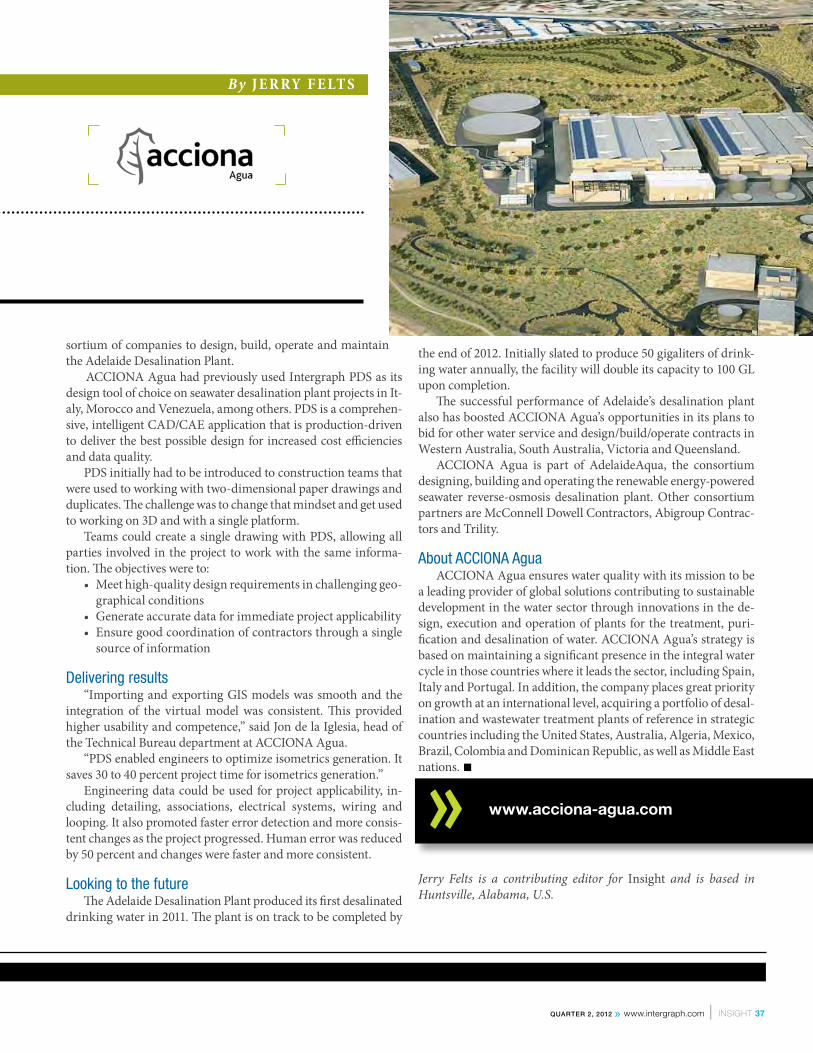
sortium of companies to design, build, operate and maintain the Adelaide Desalination Plant.
ACCIONA Agua had previously used Intergraph PDS as its design tool of choice on seawater desalination plant projects in It-aly, Morocco and Venezuela, among others. PDS is a comprehen-sive, intelligent CAD/CAE application that is production-driven to deliver the best possible design for increased cost efficiencies and data quality.
PDS initially had to be introduced to construction teams that were used to working with two-dimensional paper drawings and duplicates. The challenge was to change that mindset and get used to working on 3D and with a single platform.
Teams could create a single drawing with PDS, allowing all parties involved in the project to work with the same informa-tion. The objectives were to:
• Meet high-quality design requirements in challenging geo-graphical conditions
• Generate accurate data for immediate project applicability• Ensure good coordination of contractors through a single
source of information
Delivering results“Importing and exporting GIS models was smooth and the
integration of the virtual model was consistent. This provided higher usability and competence,” said Jon de la Iglesia, head of the Technical Bureau department at ACCIONA Agua.
“PDS enabled engineers to optimize isometrics generation. It saves 30 to 40 percent project time for isometrics generation.”
Engineering data could be used for project applicability, in-cluding detailing, associations, electrical systems, wiring and looping. It also promoted faster error detection and more consis-tent changes as the project progressed. Human error was reduced by 50 percent and changes were faster and more consistent.
Looking to the futureThe Adelaide Desalination Plant produced its first desalinated
drinking water in 2011. The plant is on track to be completed by
the end of 2012. Initially slated to produce 50 gigaliters of drink-ing water annually, the facility will double its capacity to 100 GL upon completion.
The successful performance of Adelaide’s desalination plant also has boosted ACCIONA Agua’s opportunities in its plans to bid for other water service and design/build/operate contracts in Western Australia, South Australia, Victoria and Queensland.
ACCIONA Agua is part of AdelaideAqua, the consortium designing, building and operating the renewable energy-powered seawater reverse-osmosis desalination plant. Other consortium partners are McConnell Dowell Contractors, Abigroup Contrac-tors and Trility.
About ACCIONA AguaACCIONA Agua ensures water quality with its mission to be
a leading provider of global solutions contributing to sustainable development in the water sector through innovations in the de-sign, execution and operation of plants for the treatment, puri-fication and desalination of water. ACCIONA Agua’s strategy is based on maintaining a significant presence in the integral water cycle in those countries where it leads the sector, including Spain, Italy and Portugal. In addition, the company places great priority on growth at an international level, acquiring a portfolio of desal-ination and wastewater treatment plants of reference in strategic countries including the United States, Australia, Algeria, Mexico, Brazil, Colombia and Dominican Republic, as well as Middle East nations. ■
Jerry Felts is a contributing editor for Insight and is based in Huntsville, Alabama, U.S.
www.acciona-agua.com
By J e R Ry F e LT s
Quarter 2, 2012 » www.intergraph.com l INSIGHT 37

small engineering company in Tu-nisia is making a big name for itself among international oil and gas op-erators across North Africa.
Industrial Engineering Technolo-gies (IET) was established in 2003 by SOCOMENIN, a steel manufacturer and pipe fabricator with headquarters
in the Mediterranean port city of Sfax, Tunisia. IET provides pip-ing, electricity, instrumentation and pressure vessels, among other engineering services, and has continued to expand to neighboring countries after establishing a presence in the Tunisian market with its ability to carry out turnkey projects of increasing capacity, in-cluding products of its own design. As a full-service company, IET performs project engineering and site services, along with techno-economic studies and management consulting.
Located in the hub of a petroleum-rich region, IET’s engineer-ing services and project management services have gained a foot-hold in the North Africa market by meeting the demanding needs of global oil and gas operators. And Intergraph is providing IET with the solutions it needs to support customers with complete plant design engineering services.
Rapid expansion in recent years made it necessary for IET to implement the latest technologies to provide advanced design for industrial plants while lowering costs and increasing efficiency. IET chose Intergraph solutions because they were increasingly demanded by owner operators working in North Africa. These O/Os wanted quality design for turnkey projects that could be per-formed from and delivered to different locations and online.
IET chose Intergraph solutions to:• Gain qualitative design improvements for better plant con-
figuration• Achieve flexible information flows and remote engineering
access• Streamline processes and improve project management
workflows and document management systems• Accomplish more effective change management and faster
decision-makingIET purchased SmartPlant 3D, SmartPlant P&ID and Smart-
Plant Instrumentation. The company then started a number of small projects to train its team. It now plans to obtain more rel-evant engineering projects and purchase other licenses from Inter-graph’s portfolio.
PerformanceIET had previously used a number of Intergraph products, in-
cluding PV Elite for pressure valve design and CAESAR II for pip-ing flexibility analysis and stress calculation.
It added Intergraph SmartPlant Enterprise products to expand its services. Intergraph assisted with the software implementation and the required integration with Tekla Xsteel and piping custom-ization that met French standards.
The improved performance and guaranteed results since imple-menting Intergraph products have resulted in increased customer satisfaction. IET now provides higher-quality design in a shorter period of time; work can be performed remotely; and Intergraph solutions interface more efficiently with other tools and anticipate and react to project changes.
Increasing profitabilityIET trained its employees for a year and is using SmartPlant 3D
on small projects like the extension of hydrocarbon facilities and phosphoric acid pulp units. Twelve users are currently using the tools and eight users have simultaneous access.
The company is now developing a number of tools to increase solution profitability, including the preparation of a pipe supports library and creation of an audio-visual training program covering all aspects of the tools to prepare its team for increasing the num-ber of SmartPlant 3D users.
IET’s future growth is based on broadening its engineering capabilities through full-cycle services and more integrated engi-neering. Intergraph solutions will be used in larger and more com-plex turnkey projects in Tunisia and other countries, and the sub-contract engineering activities associated with those projects are expected to boost the North African economy. ■Jerry Felts is a contributing editor for Insight and is based in Hunts-ville, Alabama, U.S.
CuSTOMer VIewpOINTS » I e T
Quality Design for Turnkey Projects
» SmartPlant 3D and SmartPlant Enterprise boost efficiency
By J e R Ry F e LT s
38 INSIGHT l Issue 31 » Quarter 2, 2012

By J e R Ry F e LT s
At A GlanceIntergraph Introduces SmartPlant FreeView™
INTERGRAPH released SmartPlant FreeView™, a free .VUE viewer that al-lows users to display and navigate Inter-graph 3D models and view associated plant properties. SmartPlant FreeView will open any SmartPlant 3D and SmartMarine 3D projects published as a .VUE file. A user then may walk through the plant, ship or offshore model and se-lect any object in the view to see its as-sociated plant properties via the MDB2 package. SmartPlant Review Publisher can convert and combine SmartPlant 3D and SmartMarine 3D, as well as oth-er project types, into .VUE and MDB2 formats for viewing with SmartPlant FreeView or SmartPlant Review.
The free .VUE viewer has a complete set of on-screen navigation controls for easy use, allowing even the most casual user to walk through complex 3D mod-els with no training. Keyboard naviga-tion is equally simple. An orientation axis is displayed in the view to help the user maintain direction. SmartPlant FreeView also has a surface measure command to display accurate distances between objects.
“On the oil sands projects in Cana-da, AMEC works with a large number of clients, partners and subcontractors who could benefit from viewing the 3D model,” said Vlad Savulian, engineer-ing systems lead for AMEC Natural Resources. “With SmartPlant Free-View, they will be able to easily navi-gate the plant model, view properties, make comments on what they see or ask
questions about what they don’t under-stand.” www.intergraph.com/go/freeview
Fluor Uses SmartPlant Enterprise on 22 Projects
FLUOR® CORPORATION, of Ir-ving, Texas, an Intergraph customer and one of the world’s leading engineering, procurement, construction and main-tenance companies, continues to imple-ment SmartPlant Enterprise solutions as its project platform for an increasing number of its global projects.
Fluor, an Intergraph customer for more than 30 years, relies on proper planning, training and business mind-set to successfully deploy SmartPlant Enterprise. Fluor currently has 22 ongo-ing projects that are using SmartPlant technology.
Intergraph and Fluor signed a five-year Global Alliance Agreement togeth-
er, covering the SmartPlant and SmartMa-rine Enterprise software suites, including SmartPlant 3D, PDS, SmartPlant Founda-tion, SmartPlant P&ID and SmartPlant Instrumentation.
“Intergraph’s solutions have been a part of our project execution toolbox for many years, helping us deliver superior capital projects to our clients,” said Peter Moore, Fluor’s vice president of Project Execution Services. “The SmartPlant En-terprise suite and automation capabilities help us to maximize a distributed project environment by enforcing consistency in the project setup and execution processes.”
www.intergraph.com/go/smartplant3d
ARC Again Ranks Intergraph as World’s No. 1
ARC ADVISORY GROUP, the leading research and advisory firm for industry and infrastructure, has again ranked Intergraph as the world’s No. 1 software provider, this time in its recently released “Process Engi-neering Tools (PET) Market Analysis and Forecast through 2015.”
The ARC study provides an in-depth analysis of the PET market for process manufacturing by industry segment and geographic region. The tools and applica-tions covered in the PET study include a large portion of those necessary to manage engineering activities that create or use en-gineering data throughout the life cycle of a plant or marine asset. Profiles for major suppliers servicing the PET market are also listed.
In addition to ranking Intergraph as the overall global leader, the ARC Advisory Group study also places Intergraph first in
40 INSIGHT l Issue 31 » Quarter 2, 2012
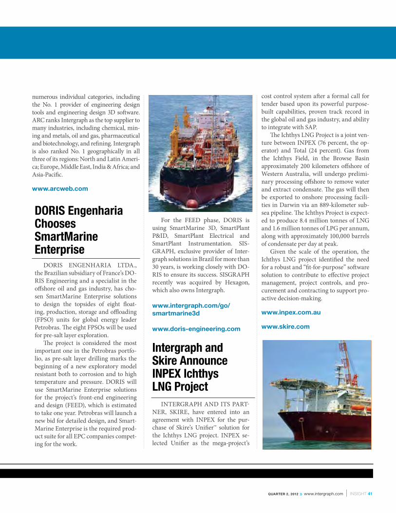
DORIS Engenharia Chooses SmartMarine Enterprise
DORIS ENGENHARIA LTDA., the Brazilian subsidiary of France’s DO-RIS Engineering and a specialist in the offshore oil and gas industry, has cho-sen SmartMarine Enterprise solutions to design the topsides of eight float-ing, production, storage and offloading (FPSO) units for global energy leader Petrobras. The eight FPSOs will be used for pre-salt layer exploration.
The project is considered the most important one in the Petrobras portfo-lio, as pre-salt layer drilling marks the beginning of a new exploratory model resistant both to corrosion and to high temperature and pressure. DORIS will use SmartMarine Enterprise solutions for the project’s front-end engineering and design (FEED), which is estimated to take one year. Petrobras will launch a new bid for detailed design, and Smart-Marine Enterprise is the required prod-uct suite for all EPC companies compet-ing for the work.
For the FEED phase, DORIS is using SmartMarine 3D, SmartPlant P&ID, SmartPlant Electrical and SmartPlant Instrumentation. SIS-GRAPH, exclusive provider of Inter-graph solutions in Brazil for more than 30 years, is working closely with DO-RIS to ensure its success. SISGRAPH recently was acquired by Hexagon, which also owns Intergraph.
www.intergraph.com/go/smartmarine3d www.doris-engineering.com
Intergraph and Skire Announce INPEX Ichthys LNG Project
INTERGRAPH AND ITS PART-NER, SKIRE, have entered into an agreement with INPEX for the pur-chase of Skire’s Unifier™ solution for the Ichthys LNG project. INPEX se-lected Unifier as the mega-project’s
cost control system after a formal call for tender based upon its powerful purpose-built capabilities, proven track record in the global oil and gas industry, and ability to integrate with SAP.
The Ichthys LNG Project is a joint ven-ture between INPEX (76 percent, the op-erator) and Total (24 percent). Gas from the Ichthys Field, in the Browse Basin approximately 200 kilometers offshore of Western Australia, will undergo prelimi-nary processing offshore to remove water and extract condensate. The gas will then be exported to onshore processing facili-ties in Darwin via an 889-kilometer sub-sea pipeline. The Ichthys Project is expect-ed to produce 8.4 million tonnes of LNG and 1.6 million tonnes of LPG per annum, along with approximately 100,000 barrels of condensate per day at peak.
Given the scale of the operation, the Ichthys LNG project identified the need for a robust and “fit-for-purpose” software solution to contribute to effective project management, project controls, and pro-curement and contracting to support pro-active decision-making. www.inpex.com.au www.skire.com
numerous individual categories, including the No. 1 provider of engineering design tools and engineering design 3D software. ARC ranks Intergraph as the top supplier to many industries, including chemical, min-ing and metals, oil and gas, pharmaceutical and biotechnology, and refining. Intergraph is also ranked No. 1 geographically in all three of its regions: North and Latin Ameri-ca; Europe, Middle East, India & Africa; and Asia-Pacific.
www.arcweb.com
Quarter 2, 2012 » www.intergraph.com l INSIGHT 41

Intergraph, the Intergraph logo, and SmartPlant are registered trademarks of Intergraph Corp. or its subsidiaries in the United States and in other countries.
EnsurE EnginEEring data intEgrity
SmartPlant Foundation is the single source of access to the engineering truth about a plant – its structure, tags, equipment, data, and documents. Choose the powerful Intergraph® information management solution to share valid, consistent, and high-quality engineering data between applications and users when and where they need it.
Streamline business processes that share common information. Reduce the cost and errors associated with multiple tools by eliminating the boundaries between them.
www.intergraph.com/go/foundation
all your data at your commandSmartPlant® Foundation
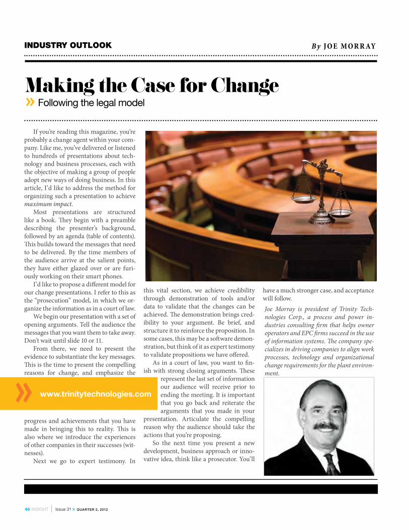
INduSTry OuTLOOK
Making the Case for Change » Following the legal model
www.trinitytechnologies.com
By J Oe M OR R Ay
If you’re reading this magazine, you’re probably a change agent within your com-pany. Like me, you’ve delivered or listened to hundreds of presentations about tech-nology and business processes, each with the objective of making a group of people adopt new ways of doing business. In this article, I’d like to address the method for organizing such a presentation to achieve maximum impact.
Most presentations are structured like a book. They begin with a preamble describing the presenter’s background, followed by an agenda (table of contents). This builds toward the messages that need to be delivered. By the time members of the audience arrive at the salient points, they have either glazed over or are furi-ously working on their smart phones.
I’d like to propose a different model for our change presentations. I refer to this as the “prosecution” model, in which we or-ganize the information as in a court of law.
We begin our presentation with a set of opening arguments. Tell the audience the messages that you want them to take away. Don’t wait until slide 10 or 11.
From there, we need to present the evidence to substantiate the key messages. This is the time to present the compelling reasons for change, and emphasize the
progress and achievements that you have made in bringing this to reality. This is also where we introduce the experiences of other companies in their successes (wit-nesses).
Next we go to expert testimony. In
this vital section, we achieve credibility through demonstration of tools and/or data to validate that the changes can be achieved. The demonstration brings cred-ibility to your argument. Be brief, and structure it to reinforce the proposition. In some cases, this may be a software demon-stration, but think of it as expert testimony to validate propositions we have offered.
As in a court of law, you want to fin-ish with strong closing arguments. These
represent the last set of information our audience will receive prior to ending the meeting. It is important that you go back and reiterate the arguments that you made in your
presentation. Articulate the compelling reason why the audience should take the actions that you’re proposing.
So the next time you present a new development, business approach or inno-vative idea, think like a prosecutor. You’ll
have a much stronger case, and acceptance will follow.Joe Morray is president of Trinity Tech-nologies Corp., a process and power in-dustries consulting firm that helps owner operators and EPC firms succeed in the use of information systems. The company spe-cializes in driving companies to align work processes, technology and organizational change requirements for the plant environ-ment.
46 INSIGHT l Issue 31 » Quarter 2, 2012

Gain a competitive edge and accelerate projects with the latest release of Intergraph®
SmartPlant® 3D, the first and only next-generation 3D plant design solution for the process and power industries. SmartPlant 3D delivers at least 30 percent more productivity than any other system available today.
SmartPlant 3D now offers powerful rules and relationships that automate repetitive tasks, enforce design standards, ensure design integrity, and protect design consistency. Benefit from enhanced support for mega-projects thanks to global worksharing, model data reuse, and safety-centric rules.
To see demonstrations, case studies, webinars, and more, visit www.intergraph.com/go/smartplant3d.
boost productivity by 30 percentSmartPlant® 3D
Intergraph, the Intergraph logo, and SmartPlant are registered trademarks of Intergraph Corp. or its subsidiaries in the United States and in other countries.