power plant and transmission system pt ti c di tiprotection … dl/protection-system-device-… ·...
TRANSCRIPT

Power Plant and Transmission System Power Plant and Transmission System P t ti C di tiP t ti C di tiProtection CoordinationProtection Coordination
LossLoss--ofof--Field (40) and OutField (40) and Out--ofof--Step Protection (78)Step Protection (78)
NERC Protection Coordination Webinar SeriesJune 30, 2010
Dr. Murty V.V.S. Yalla

DisclaimerDisclaimer2
The information from this webcast is provided for i f ti l l A tit ' dh t thinformational purposes only. An entity's adherence to the examples contained within this presentation does not constitute compliance with the NERC Compliance Monitoring and Enforcement Program ("CMEP") requirements, NERC g ( ) q ,Reliability Standards, or any other NERC rules. While the information included in this material may provide some of the methodology that NERC may use to assess compliance with the requirements of certain Reliability Standards this materialthe requirements of certain Reliability Standards, this material should not be treated as a substitute for the Reliability Standard or viewed as additional Reliability Standard requirements. In all cases, the entity should rely on the l t i d i th R li bilit St d d it lf d tlanguage contained in the Reliability Standard itself, and not on the language contained in this presentation, to determine compliance with the NERC Reliability Standards.

3AgendaAgenda
Technical Reference Document Overview
Objectives
Description of Protection Functionsp
Stability Fundamentals and Examples
Discuss and Describe System Events that Could CreateDiscuss and Describe System Events that Could Create Conditions that Would Cause Operation of These Functions
Detailed Coordination Information• Function 40 – Loss-of-Field (a.k.a. Loss-of-Excitation)
• Function 78 Out of Step• Function 78 – Out-of-Step

4AgendaAgenda
What is Important to CoordinationWhat is Important to Coordination• Settings that Protect the Generator
C iti l Cl i Ti• Critical Clearing Time
• Worst Case Survivable Condition
• Sufficient Studies
Question and Answer

5Technical Reference Document OverviewTechnical Reference Document Overview
Introduction and Background – BlackoutIntroduction and Background Blackout Recommendation TR-22• SPCS’s AssignmentSPCS s Assignment
The Need for this Technical Reference Document History and Background:Document - History and Background: • August 14, 2003 Blackout
• Subsequent Events

6Technical Reference Document OverviewTechnical Reference Document Overview
Support of PRC StandardsSupport of PRC Standards
Benefits of Coordination:• To the Generator Owner
• To the Transmission Owner
• To the Planning Coordinator
Reliability of the Bulk Electric System and PowerReliability of the Bulk Electric System and Power Delivery to the Customer

7ObjectiveObjective
Increase knowledge of recommendedIncrease knowledge of recommended generator protection for Loss-of-Field and Out-of-Step.
Facilitate improved coordination between power plant and transmission system p p yprotection for these specific protection functions.
8Scope Scope
Focus is on the reliability of the Bulk ElectricFocus is on the reliability of the Bulk Electric System.
This Technical Reference Document is This Technical Reference Document is applicable to all generators, but concentrates on synchronous generators connected at 100-kV y gand above.
Distributed Generation (DG) facilities connected Distributed Generation (DG) facilities connected to distribution systems are outside the scope of this document.

9
The Need for LossThe Need for Loss--ofof--Field Field Protection Protection –– Function 40Function 40
“The source of excitation for a generator may be g ycompletely or partially removed through such incidents as accidental tripping of a field breaker, field open circuit, field short circuit (flashover of the slip rings), voltage ( p g ) gregulation system failure, or the loss of supply to the excitation system. Whatever the cause, a loss of excitation may present serious operating conditions for y p p gboth the generator and the system.
When a generator loses its excitation, it overspeeds and operates as an induction generator It continues tooperates as an induction generator. It continues to supply some power to the system and receives its excitation from the system in the form of vars.”
IEEE C37.102-2006 – Guide for AC Generator Protection, Section 4.5.1

10
The Need for LossThe Need for Loss--ofof--Field Field Protection Protection –– Function 40Function 40
Loss of field can occur due to:Loss of field can occur due to:• Accidental tripping of a field breaker.
Fi ld i it fi ld h t i it (fl h f th• Field open circuit or field short circuit (flashover of the slip rings).
• Voltage regulation system failure or the loss of• Voltage regulation system failure, or the loss of supply to the excitation system.

11
The Need for LossThe Need for Loss--ofof--Field Field Protection Protection –– Function 40Function 40
Loss of excitation may present serious operating y p p gconditions for both the generator and the system.
Generator effects:• Generator overspeeds and operates as an induction
generator receiving its excitation from the system.
• Stator currents can exceed 2 pu causing dangerous overheating of the stator winding and coreoverheating of the stator winding and core.
• High levels of slip-frequency currents can be induced in the rotor causing over heating of the rotor.g g

12
The Need for LossThe Need for Loss--ofof--Field Field Protection Protection –– Function 40Function 40
Power System effects:Power System effects:• A loss of field condition causes devastating impact on
the power system due to loss of reactive power p y psupport from the generator.
• Creates a substantial reactive power drain from the system.
• On large generators this condition can contribute to or i id l lltrigger a wide area system voltage collapse

13
The Need for LossThe Need for Loss--ofof--Synchronism Synchronism Protection Protection –– Function 78Function 78
“The protection normally applied in the generator zone, such as differential relaying time delay system backup etc will not detect loss ofrelaying, time-delay system backup, etc., will not detect loss of synchronism. The loss-of-field relay may provide some degree of protection but cannot be relied on to detect generator loss of synchronism under all system conditions. Therefore, if during a loss of synchronism the electrical center is located in the region from the high-voltage terminals of the GSU g g gtransformer down into the generator, separate out-of-step relaying should be provided to protect the machine. This is generally required for larger machines that are connected to EHV systems.
On large machines the swing travels through either the generator or theOn large machines the swing travels through either the generator or the main transformer. This protection may also be required even if the electrical center is out in the system and the system relaying is slow or cannot detect a loss of synchronism. Transmission line pilot-wire relaying, current-differential relaying, or phase comparison relaying will not detect a loss of
h i F t t d t l lt tsynchronism. For generators connected to lower voltage systems, overcurrent relaying may not be sensitive enough to operate on loss of synchronism.”
IEEE C37.102-2006 – Guide for AC Generator Protection, Section 4.5.3.1
14
The Need for LossThe Need for Loss--ofof--Synchronism Synchronism Protection Protection –– Function 78Function 78
During an out-of-step or pole slip condition the voltage it d b t th t d th tmagnitude between the generator and the system
reaches two per unit (at 180 degrees) which can result in high currents that cause mechanical forces in the generator stator windings and undesired transient shaftgenerator stator windings and undesired transient shaft torques.
It is possible for the resulting torques to be of sufficient it d th t th i d t thmagnitude so that they cause serious damage to the
shaft and to the turbine blades. It can cause excessive overheating and shorting at the g g
ends of the stator core. It can also cause damaging transient forces in the
windings of the GSU transformer as wellwindings of the GSU transformer as well.

15
Relay OneRelay One--Line Showing All Generator Line Showing All Generator Protection and Identifying Function 40 and 78Protection and Identifying Function 40 and 78
51T
87G
87T
87U
87G
24 27 59 81
R
51TG
50BF
59GN/ 27TH
21 32 40 46 51V 7850/2740 78

16Stability FundamentalsStability Fundamentals
Power System Stability - “If the oscillatory response of a power system during the transient period following a disturbance issystem during the transient period following a disturbance is damped and the system settles in a finite time to a new steady operating condition we say the system is stable. If the system is not stable, it is considered unstable.”
Stability is a property of an electrical power system which has two or more synchronous machines. A system is stable for a specific set of conditions if all synchronous machines remain in step with each other. A system can be stable for one set of conditions and unstableother. A system can be stable for one set of conditions and unstable for another.
Transient Stability Swing Equation Accelerating Torque Equals Mechanical Torque Swing Equation – Accelerating Torque Equals Mechanical Torque
Minus Electrical Torque Ta = Tm - Te Newton Meters
Eq al Area Criterion Equal Area Criterion

Equal Area Method to Equal Area Method to Determine StabilityDetermine Stabilityyy

18Stability Study ExamplesStability Study Examples
This group of protective functions (Function 40 and 78) needs to be validated against transient stability studies to insure that t i i d t f t bl i d i
Sample apparent impedance swings are presented in this figure for a dual lens characteristic out-of-step relay In this figure
tripping does not occur for stable impedance swings.
characteristic out-of-step relay. In this figure the time interval between markers is 100 ms (6 cycles) such that the faster swings have greater distance between markers. The three traces represent marginally stable and
f funstable swings for fault clearing at and just beyond the critical clearing time, and a trace for the worst credible contingency representing the fastest unstable swing
Marginally Stable Swing Marginally Unstable Swing Worst Case (Fastest) Unstable
SwingNotes: Time between markers ()
is 100 msScale is apparent impedancein secondary ohms

19
System Events that Could Cause Undesired System Events that Could Cause Undesired Operation of These Protection FunctionsOperation of These Protection Functions
Fault ConditionsFault Conditions
Loss of Critical Lines
Loss of Critical Units
Events such as August 14, 2003 Blackoutg ,
System Islanding Conditions

20
General Data Exchange Requirements General Data Exchange Requirements ––Generator Owner Data and InformationGenerator Owner Data and Information
The following general information must be exchanged in addition to relay settings to facilitate coordination where applicable:relay settings to facilitate coordination, where applicable:• Relay scheme descriptions• Generator off nominal frequency operating limits• CT and VT/CCVT configurations • Main transformer connection configuration• Main transformer tap position(s) and impedance (positive and zero
sequence) and neutral grounding impedances• High voltage transmission line impedances (positive and zero
sequence) and mutual coupled impedances (zero sequence)Generator impedances (sat rated and nsat rated reactances that• Generator impedances (saturated and unsaturated reactances that include direct and quadrature axis, negative and zero sequence impedances and their associated time constants)
• Documentation showing the function of all protective elements listed babove

21
General Data Exchange Requirements General Data Exchange Requirements ––Transmission or Distribution Owner Data and InformationTransmission or Distribution Owner Data and Information
The following general information must be exchanged in addition to relay settings to facilitate coordination where applicable:relay settings to facilitate coordination, where applicable:• Relay scheme descriptions• Regional Reliability Organization’s off-nominal frequency plan • CT and VT/CCVT configurations• Any transformer connection configuration with transformer tap
position(s) and impedance (positive and zero sequence) and neutral grounding impedancesgrounding impedances
• High voltage transmission line impedances (positive and zero sequence) and mutual coupled impedances (zero sequence)
• Documentation showing the function of all protective elementsg p• Results of fault study or short circuit model• Results of stability study• Communication aided schemes• Communication-aided schemes

22
Detailed Coordination Information Detailed Coordination Information for Functions 40 and 78for Functions 40 and 78
Detailed coordination information is presentedDetailed coordination information is presented under seven headings, as appropriate, for each function in the document.
The following slides present a section-by-section summary for Functions 40 and 78.y

23
Document Format Document Format –– Seven SubSeven Sub--Sections Sections for Each Protection Functionfor Each Protection Function
Purpose Coordination of Generator and Transmission Systemy
• Faults• Loadability• Other Conditions, where applicable, pp
Considerations and Issues Coordination Procedure
• Test Procedure for ValidationTest Procedure for Validation • Setting Considerations
Examples• Proper CoordinationProper Coordination• Improper Coordination
Summary of Detailed Data Required for Coordination of the Protection Function
Table of Data and Information that must be Exchanged

24LossLoss--ofof--Field Field –– Function 40Function 40
Purpose• Detect and prevent unsafe and damaging operation of the
fgenerator during loss-of-excitation events.
Loss of Field protection characteristic on the R-X diagram
Figure 3.5.1 — (1) Locus of Swing Impedance during Light and Heavy Loads for Loss-of-Field, and(2) Relationship between Minimum Excitation Limiter (MEL) or Under Excitation Limiter (UEL)

25
Coordination of Generator and Coordination of Generator and Transmission System Transmission System –– Function 40Function 40
Faults• Step 1 — The Transmission Owner provides the Planning Coordinator with the
worst case clearing time for each of the power system elements connected to theworst case clearing time for each of the power system elements connected to the generator bus.
• Step 2 — The Planning Coordinator determines the stability impedance trajectory for the above conditions.Step 3 The Planning Coordinator provides these plots to the Generator• Step 3 — The Planning Coordinator provides these plots to the Generator Owner. The Generator Owner utilizes these plots to demonstrate that these impedance
trajectories coordinate with the time delay setting of the loss-of-field (LOF) relay to prevent misoperations by having adequate time delay.
• A system stability study may be required to evaluate the generator and system response to power system faults. The response of the LOF relays under these conditions must be studied to see if they
respond to power swing conditions as a result of system faults. The Transmission Owner, Generator Owner, and Planning Coordinator must share
information on these studies and LOF relay settings to prevent inadvertent tripping of generators for external fault conditions not related to a loss-of-field condition.
If there is an out-of-step protection installed it should be coordinated with the LOF protection.protection.

26
Coordination of Generator and Coordination of Generator and Transmission System Transmission System –– Function 40Function 40 Loadability
• Step 1 — The Generator Owners confirms that the LOF relay setting coordinates with the generator reactive capability and the excitation system capability to g p y y p yensure that the LOF relay does not restrict operation of the generating unit.
• Step 2 — A light load system study is completed in which the generator is taking in vars. A sufficient number of operating conditions and system contingencies are evaluated to p g y g
identify the worst case operating condition for coordination with the LOF relay setting. The output of this study is provided to the Generator Owner to evaluate whether the
worst case operating load condition(s) lies outside the LOF characteristic.
• Step 3 — For any case where the operating load point lies within a properly set LOF h t i ti t ll d l ti t b li d (i h tLOF characteristic a mutually agreed upon solution must be applied, (i.e., shunt reactor, turning off capacitor banks in the area, etc). Where the solution requires real-time action by an operator the solution is incorporated
into a system operating procedure.
Coordination between Generator Owners Transmission Owners and Planning• Coordination between Generator Owners, Transmission Owners, and Planning Coordinators is necessary to prevent loadability considerations from restricting system operations. This is typically not a problem when the generator is supplying VARs because the LOF
characteristics are set to operate in third and fourth quadrant. p q However, when the generator is taking in VARs due to light load and line charging
conditions, or failure of a transmission capacitor bank to open due to control failure, loss-of-field relays can misoperate if the apparent impedance enters the relay characteristic in the fourth quadrant.

27Considerations and Issues Considerations and Issues –– Function 40Function 40
The LOF relay settings must be provided to the Planning Coordinator by the Generator Owner so that the PlanningCoordinator by the Generator Owner so that the Planning Coordinator can determine if any stable swings encroach long enough in the LOF relay trip zone to cause an inadvertent trip.
The Planning Coordinator has the responsibility to periodically verifyThe Planning Coordinator has the responsibility to periodically verify that power system modifications do not result in stable swings entering the trip zone(s) of the LOF relay causing an inadvertent trip.
If permanent modifications to the power system cause the stable i i d t j t t t th LOF h t i ti th thswing impedance trajectory to enter the LOF characteristic, then the
Planning Coordinator must notify the Generator Owner that new LOF relay settings are required.
The Planning Coordinator should provide the new stable swing The Planning Coordinator should provide the new stable swing impedance trajectory so that the new LOF settings will accommodate stable swings with adequate time delay. The new settings must be provided to the Planning Coordinator from the Generator Owner for periodic assessment in future studiesGenerator Owner for periodic assessment in future studies.

28Coordination Considerations –– Function 40Function 40
The coordination requirements with generatorThe coordination requirements with generator controls are such that the loss-of-field relay must not operate before the UEL limit (with a margin) is reached.

29
Example Example -- Proper Coordination Proper Coordination –– Function 40Function 40
Typical Loss-of-Field Relay Setting Calculation for two zone offset mho characteristic (calculations are in transmission system primary ohms).
Step-1 — Calculate the Base impedance = 17.56 Ω/per unitStep 1 Calculate the Base impedance 17.56 Ω/per unit Step-2 — Convert X’d and Xd in per unit to Ohms:
• 3.61 Ω• 20.88 Ω
Step-3 — Element settings:• Offset = (50%) (X’d) = (0.5) (3.61) = 1.8 Ω• Z1 = 1 pu = 17.6 Ω• Z2 = = 20.88 Ω
Step-4 — Plot various characteristics as shown in figure 3.5.1 Step-5 — set the time delays for zone 1 and zone 2 elements.
• Typical time delay settings are:1 0 1• Zone 1: 0.1 sec
• Zone 2: 0.5 sec System stability studies should be conducted to see if the above time delays are sufficient to
prevent inadvertent tripping during stable power swings. Figure 3.5.3 illustrates some of these types of swing characteristics that need to be studied. Step-6 — Set the undervoltage supervision (if appropriate):
• V = 85% of = 0.85 x 120V =102 V

30
Example Example -- Proper CoordinationProper Coordination–– Function 40Function 40
System stability studies should be conducted to ensure the time delay settings are sufficient to prevent inadvertent tripping during stable power swings.

31
Summary of Protection Functions Summary of Protection Functions Required for Coordination Required for Coordination –– Function 40Function 40qq
Table 2 Excerpt — Function 40 Protection Coordination Considerations
Generator Protection FunctionTransmission System Protection
FunctionsSystem Concerns
Functionsy
40 – Loss of Field (LOF)Settings used for planning and system studies
Preventing encroachment on reactive capability curve
See details from sections 4.5.1 and A.2.1 of C37.102‐2006
It is imperative that the LOF function does not operate for stable power swings – The impedance trajectory of most units with a lagging power factor (reactive power into the power system) for stable swings will pass into and back out of the first and secondstable swings will pass into and back out of the first and second quadrants

32
Protection Function Data and Information Protection Function Data and Information Exchange Required for Coordination Exchange Required for Coordination –– Function 40 Function 40 c a ge equ ed o Coo d at oc a ge equ ed o Coo d at o u ct o 0u ct o 0
Table 3 Excerpt — Function 40 Data to be Exchanged Between Entities
Generator Owner Transmission Owner Planning CoordinatorGenerator Owner Transmission Owner Planning Coordinator
Relay settings: loss of field characteristics, including time delays, at the generator terminals
Generator reactive capability
The worst case clearing time for each of the power system elements connected to the transmission bus at which the generator is connected
Impedance trajectory from system stability studies for the strongest and weakest available system
Feedback on problems found in coordination and stability studies

33Loss of Synchronism Loss of Synchronism –– Function 78Function 78
Purpose• Detect and prevent unsafe and damaging operation of the
f
generator during out-of-step events.
A B C
Figure 3.13.1 — Loci of Swing by Eg/Es

34Loss of Synchronism Loss of Synchronism –– Function 78Function 78
Figures 3.13.1A and 3.13.1B illustrate a simple g prepresentation of two (2) systems Es (power system) and Eg (a generator) connected through a GSU transformertransformer.• Figure 3.13.1C shows typical power swing loci which are
dependent on the ratio of Eg / Es.
• When Eg is less than Es, which may occur when the generator is underexcited, the power swing loci will appear electrically “closer” to the generator than the power system. g p y
• Due to the variability of the apparent impedance trajectory it is desirable to base out-of-step protection settings on transient stability simulationsstability simulations.

35
Coordination of Generator and Coordination of Generator and Transmission System Transmission System –– Function 78Function 78yy
FaultsFaults• There are no coordination issues for system faults for
this function, although the apparent impedance , g pp pswings for which out-of-step protection must be coordinated often occur as the result of system faults.
Loadability• There are no coordination issues related to loadability y
for this function.

36
Coordination of Generator and Coordination of Generator and Transmission System Transmission System –– Function 78Function 78yy Other Operating Conditions
• A generator may pole-slip (out-of-step or loss-of-synchronism), or fall t f h i ith th t f b fout of synchronism with the power system for a number of reasons.
The primary causes are: Prolonged clearance of a low-impedance fault on the power system. Generator operation at a high load angle close to its stability limit.Generator operation at a high load angle close to its stability limit. Partial or complete loss of excitation.
• To properly apply this protection function, stability studies must be performed. These studies: Require extensive coordination. Usually are conducted by the Transmission Planner or Planning Coordinator. Should evaluate a wide variety of system contingency conditions.
• Out-of-step protection Should not be applied unless stability studies indicate that it is needed. Should be applied in accordance with the results of those studies. Must be reviewed as system conditions change.

37
Coordination of Generator and Coordination of Generator and Transmission System Transmission System –– Function 78Function 78yy Other Operating Conditions (continued)
• Studies must be used to verify that the out-of-step protection:y p p Provides dependable tripping for unstable swings.
Provides secure operation for stable swings.
• The critical conditions for setting the relay are:The critical conditions for setting the relay are: The marginal condition representing the unstable swing that is closest to a
stable condition.
The fastest swing typically resulting from the most severe system condition.g yp y g y
• Typically the out-of-step settings are developed by: Calculating initial settings for blinders, time delay, etc. using a graphical
approach.
Refining the settings as necessary based on transient stability simulations.
• This process requires an exchange of information between the Transmission Owner(s), the Generator Owners(s) and the Transmission Planner and/or Planning Coordinator.

38Coordination ProcedureCoordination Procedure
1. Model the overall system and carry out transient stability runs for representative operating conditions. The modeling of the
t h ld i l d th lt l t XXgenerators should include the voltage regulator, generator governor and power system stabilizer (PSS) if in service.
2. Determine values of generator transient reactance (X’d) unit transformer reactance
A BD
X
XmaxSG1SYSTEM
O
A BD
X
XmaxSG1SYSTEM
Oreactance (X d), unit transformer reactance (XTG) and system impedance under maximum generation (XmaxSG1).
3. Set the Mho unit to limit the reach to 1.5 times the transformer impedance in the system
P
MR
1.5 X TGO
TRANSTGX
O
P
MR
1.5 X TGO
TRANSTGX
O
p ydirection. In the generator direction the reach is typically set at twice generator transient reactance. Therefore the diameter of the MHO characteristic is 2 X’d + 1.5 XTG.
Swing Locus
ELEMENTMHO
dA B
2X´dGEN
dX´
Swing Locus
ELEMENTMHO
dA B
2X´dGEN
dX´
d TG
4. Determine by means of the transient stability runs, the critical angle δ between the generator and the system by means of the transient stability simulations. This is the angle corresponding to fault clearing just greater than
C
ELEMENTSBLINDER
ELEMENTPICK-UP
ELEMENTPICK-UP
A B
C
ELEMENTSBLINDER
ELEMENTPICK-UP
ELEMENTPICK-UP
A B
corresponding to fault clearing just greater than the critical clearing time.

39Coordination Procedure (cont.)Coordination Procedure (cont.)
5. Determine the blinder distance d, which is calculated with the following expression:
DX
DX
6. Determine the time for the impedance trajectory
A BD
1 5 X
XmaxSG1SYSTEM
O
A BD
1 5 X
XmaxSG1SYSTEM
O6. Determine the time for the impedance trajectory to travel from the position corresponding to the critical angle δ to that corresponding to 180°. This time is obtained from the rotor angle vs. time curve which is generated by the transient stability study for the most severe transmission
P
MR
1.5 X TGO
TRANSTGX
O
P
MR
1.5 X TGO
TRANSTGX
O
stability study for the most severe transmission fault, when the system experiences the first slip.
7. The time delay of the 78 function should be set equal to the value obtained from the transient t bilit t d i t 6 Thi l i l t
Swing Locus
ELEMENTMHO
dA B
2X´dGEN
dX´
Swing Locus
ELEMENTMHO
dA B
2X´dGEN
dX´
stability study in step 6. This value is equal to half the time for the apparent impedance to travel between the two blinders and provides adequate margin to permit tripping for faster swings, while providing security against
ti f f lt diti
C
ELEMENTSBLINDER
ELEMENTPICK-UP
ELEMENTPICK-UP
A B
C
ELEMENTSBLINDER
ELEMENTPICK-UP
ELEMENTPICK-UP
A B
operation for fault conditions.

40Determination of Timer SettingDetermination of Timer Setting

41Determination of Timer SettingDetermination of Timer Setting
The fault inception will be considered at t = 0.5 seconds Clearing times starting at t = 90 ms (approx. 5 cycles) will be used in
consecutive steps of 10 ms. For simplicity, the fault is removed with the consequent outage of
th lithe line. The voltage regulator is IEEE type ST1 excitation system.
• This voltage regulator is of static excitation type where the rectifiers g g yprovide enough DC current to feed the generator field.
• The model represents a system with the excitation power supplied from a transformer fed from the generator terminals or from the auxiliary services and is regulated by controlled rectifiers. g y
The turbine-governor is IEEE type 1 Speed Governing Model. This model represents the system of speed control (Mechanical-Hydraulic) and steam turbine.
For this machine no power system stabilizer is available.

42Determination of Timer SettingDetermination of Timer Setting
Rotor Angle Generator G_1Angle (degree)
200220240260
Case1 (tc=90 ms), with controls
Case2 (tc=180 ms), with controls
Case3 (tc=190 ms), with controls
120140160180
Case3 (tc 190 ms), with controls
Case1 (tc=90 ms), without controls
Case2 (tc=180 ms), without controls
Case3 (tc=190 ms), without controls
20406080
100
-40-20
020
0.0 0.5 1.0 1.5 2.0 2.5 3.0 3.5 4.0 4.5 5.0
Time (s)Time (s)
Figure G-4

43Determination of Timer SettingDetermination of Timer Setting
Several plots from the transient stability runs can be obtained for a myriad of applications For setting out of step elements the most importantof applications. For setting out-of-step elements the most important information is the Rotor Angle vs. Time and R + j X vs. time.
From the respective plots it can be observed that:• In Case 1, with a clearing time of 90 milliseconds, the system remains in , g , y
synchronism. • In Case 2, G1 and the system are still in synchronism with a clearing time of 180
milliseconds. • In Case 3 G1 loses synchronism with a clearing time of 190 ms From theIn Case 3, G1 loses synchronism with a clearing time of 190 ms. From the
above it is evident that the critical time to clear the fault is equal to 180 ms after fault inception.
The rotor angles for the three cases are shown in Figure G-4, from which it can be seen that the critical angle is approximately 140°. The time for thecan be seen that the critical angle is approximately 140 . The time for the swing locus to travel from the critical angle to 180° is approximately 250 milliseconds.
Therefore the time delay setting should be set to 250 milliseconds.

44Determination of Timer SettingDetermination of Timer Setting
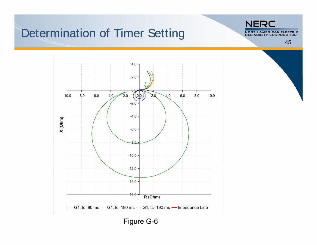
R vs. X diagrams for the three cases show the impedance trajectory b h l d i h di b Wh h iseen by the relay during the disturbances. When there is an
oscillation in the generator which is stable, the swing locus does not cross the impedance line.
Wh t t f t th t i t i th When generator goes out-of-step, the transient swing crosses the system impedance line each time a slip is completed and the relay should trip the generator.
Fi G 6 h th R X di f 1 2 d 3 Figure G-6 shows the R vs. X diagram for cases 1, 2, and 3. • In the first two cases it is clear that the load point does not cross the
system impedance line.
• For case 3, the load point crosses the system impedance line indicating that the synchronism is lost and therefore out-of-step tripping must be allowed.
45Determination of Timer SettingDetermination of Timer Setting
2 0
4.0
-2.0
0.0
2.0
-10.0 -8.0 -6.0 -4.0 -2.0 0.0 2.0 4.0 6.0 8.0 10.0
-6.0
-4.0
X (O
hm)
-12 0
-10.0
-8.0
-16.0
-14.0
-12.0
R (Ohm)
G1, tc=90 ms G1, tc=180 ms G1, tc=190 ms Impedance Line
Figure G-6

46
Example Example -- Proper Coordination Proper Coordination –– Function 78Function 78

47
Example Example -- Proper Coordination Proper Coordination –– Function 78Function 78
Check List • The direct axis transient reactance (Xd’) used in the settingThe direct axis transient reactance (Xd’) used in the setting
calculation should be on the generator voltage base.• The GSU transformer reactance (Xt) used in the setting
calculation should be on the generator voltage base.g g• The reverse reach should be greater than GSU transformer
reactance (Xt).• A proper angular separation δ[1] between the generator and theA proper angular separation δ[1] between the generator and the
system should be used to set the blinders (as determined by a transient stability study).
• A power system stability study should be performed for the relay ti d l ttitime delay setting.
[1] Note: Pursuant to C37.102, with regard to setting of the blinder, the l δ i th l ti b t th t d thangle δ is the angular separation between the generator and the
system, at which the relay determines instability. If a stability study is not available, this angle is typically set at 120º.
48
Example Example -- Proper Coordination Proper Coordination –– Function 78Function 78
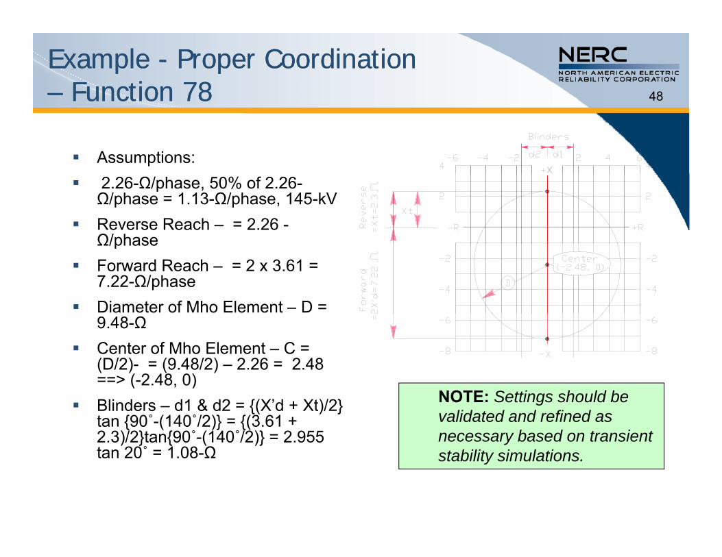
Assumptions: 2.26-Ω/phase, 50% of 2.26-
Ω/phase = 1.13-Ω/phase, 145-kV Reverse Reach – = 2.26 -
Ω/phaseΩ/phase Forward Reach – = 2 x 3.61 =
7.22-Ω/phase Diameter of Mho Element – D =
9.48-Ω Center of Mho Element – C =
(D/2)- = (9.48/2) – 2.26 = 2.48 ==> (-2.48, 0) ( 2.48, 0)
Blinders – d1 & d2 = (X’d + Xt)/2 tan 90˚-(140˚/2) = (3.61 + 2.3)/2tan90˚-(140˚/2) = 2.955 tan 20˚ = 1 08-Ω
NOTE: Settings should be validated and refined as necessary based on transient stability simulationstan 20 = 1.08-Ω stability simulations.
49
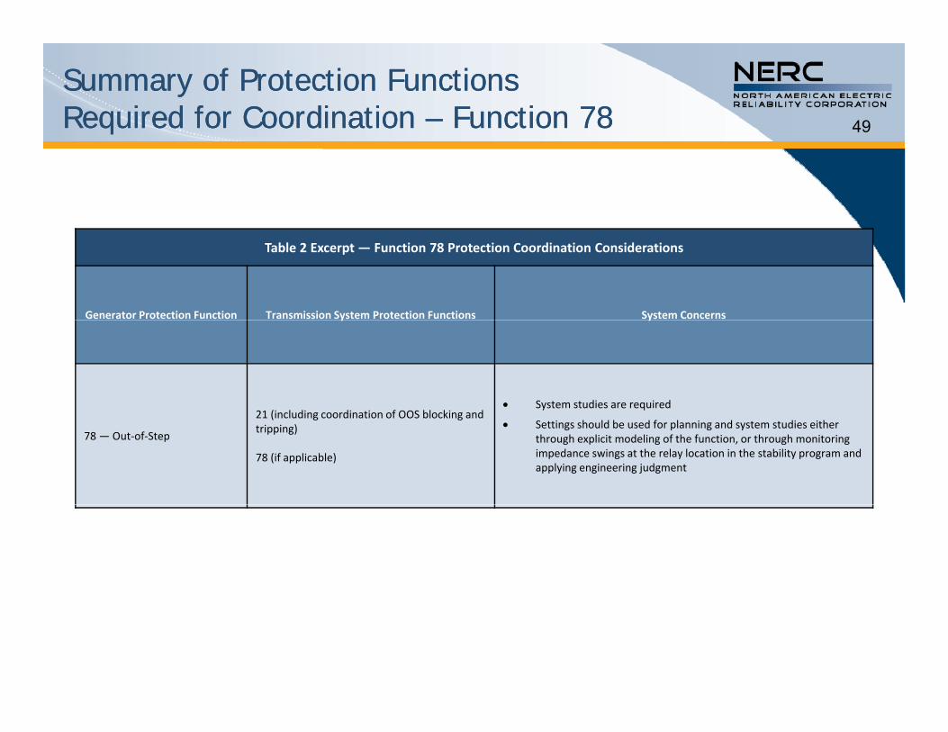
Summary of Protection Functions Summary of Protection Functions Required for Coordination Required for Coordination –– Function 78Function 78
Table 2 Excerpt — Function 78 Protection Coordination Considerations
Generator Protection Function Transmission System Protection Functions System Concerns y y
21 (i l di di ti f OOS bl ki d System studies are required
78 —Out‐of‐Step
21 (including coordination of OOS blocking and tripping)
78 (if applicable)
Settings should be used for planning and system studies either through explicit modeling of the function, or through monitoring impedance swings at the relay location in the stability program and applying engineering judgment

50
Protection Function Data and Information Protection Function Data and Information Exchange Required for Coordination Exchange Required for Coordination –– Function 78Function 78
Table 3 Excerpt — Function 78 Data to be Exchanged Between Entities
Generator Owner Transmission Owner Planning Coordinator
Determine if there is a need for generator out‐of‐step protection
Relay settings, time delays and characteristics for out‐of‐step tripping and blocking
Provide relay settings, time delays and characteristics for the out‐of‐step tripping and blocking if used
Determine if there is a need for transmission line out‐of‐step tripping/blocking related to the generator
Feedback on coordination problems found in stability studies.

51What is Important to CoordinationWhat is Important to Coordination
Settings that Protect the GeneratorSettings that Protect the Generator
Critical Clearing Time
Worst Case Survivable Condition
Sufficient Studies

52Settings that Protect the GeneratorSettings that Protect the Generator
The generator protection set-points areThe generator protection set points are described in the IEEE Guide for AC Generator Protection (C37.102) for both Function 40 and 78 based on machine and system reactance.
The time to trip are adjusted based on the p jspecific generator and application.
Examples of these were given in the Examples of these were given in the presentation, but again, specific settings need to be determined by the entities.y

53Critical Clearing TimeCritical Clearing Time
Clearing time directly impacts the ability toClearing time directly impacts the ability to return to a stable system following a system disturbance.
If fault clearing exceeds the unit critical clearing time then the machine will lose synchronism ywith the system and is required to trip.

54Worst Case Survivable ConditionWorst Case Survivable Condition
The protection must be set to avoid unnecessary tripping for worst i bl di icase survivable conditions:
• Operation of transmission equipment within continuous and emergency thermal and voltage limits
• Recovery from a stressed system voltage condition for an extreme system event – i.e. 0.85 pu voltage at the system high side of the generator step-up transformer
Stable po er s ings• Stable power swings
• Transient frequency and voltage conditions for which UFLS and UVLS programs are designed to permit system recovery
When coordination cannot be achieved without compromising protection of the generator, the generator protection setting must be accounted for in system studies.

55Sufficient StudiesSufficient Studies
The Planning Coordinator must study a number of g yoperating conditions sufficient to bound the worst case.
Assess sensitivity of generator and system response to:• System load level
• Generator loading (both active and reactive power)
• Commitment and dispatch of other generators
• System operating states (N-0, N-1, . . .)
The most limiting operating condition may vary among protective functions or even for different settings for a single protective functionsingle protective function.

56
Question & AnswerQ
Contact:
Phil Tatro, System Analysisand Reliability [email protected] 612 1158508.612.1158