power systems development facility - digital library/67531/metadc689527/...power systems development...
TRANSCRIPT

€33 01
€33 €33
DOE/MC/25140 -- 5732
Power Systems Development Facility
RECEIVED Quarterly Report
January 1 - March 31,1997
Work Performed Under Contract No.: DE-FC21-90MC25 140
For US. Department of Energy
Office of Fossil Energy Federal Energy Technology Center
Morgantown Site P.O. Box 880
Morgantown, West Virginia 26507-0880
BY Southern Company Services, Inc.
P.O. Box 1069 Wilsonville, Alabama 35 186
5~ OF T).OIS DOCURR 1s

Disclaimer
This report was prepared as an account of work sponsored by an agency of the United States Government. Neither the United States Government nor any agency thereof, nor any of their employees, makes any warranty, express or implied, or assumes any legal liability or responsibility for the accuracy, completeness, or usefulness of any information, apparatus, product, or process disclosed, or represents that its use would not infringe privately owned rights. Reference herein to any specific commercial product, process, or service by trade name, trademark, manufacturer, or otherwise does not necessarily constitute or imply its endorsement, recommendation, or favoring by the United States Government or any agency thereof. The views and opinions of authors expressed herein do not necessarily state or reflect those of the United States Government or any agency thereof.

POWER SYSTEMS DEVELOPMENT FACILITY
QUARTERLY TECHNICAL PROGRESS REPORT JANUARY 1 . MARCH 31. 1997
TABLE OF CONTENTS
1.0 INTRODUCTION AND SUMMARY .............................................................................. 1-1
2.0 OUTLINE FOR QUARTERLY PROGRESS REPORTS ............................................. 2-1
3.0 FOSTER WHEELER APFBC .......................................................................................... 3-1
4.0 M . W . KELLOGG TRANSPORT REACTOR PROCESS ........................................... 4-1
5.0 PCD/ASH SAMPLING ...................................................................................................... 5-1
6.0 AUXILIARIES AND BALANCE OF PLANT ................................................................ 6-1
7.0 SUPPORT SERVICES ...................................................................................................... 7-1
8.0 PROJECT MANAGEMENT ............................................................................................ 8-1
9.0 FUTURE PLANS ............................................................................................................... 9-1
APPENDIX A ..................................................................................................................... A-1
.. 11

1.0 INTRODUCTION AND SUMMARY
This quarterly technical progress report summarizes the work completed during the first quarter, January 1 through March 3 1, 1997, under the Department of Energy (DOE) Cooperative Agreement No. DE-FC21-90MC25 140 entitled "Hot Gas Cleanup Test Facility for Gasification and Pressurized Combustion." The objective of this project, herein referred to as the Power Systems Development Facility (PSDF), is to evaluate hot gas particle control technologies using coal-derived gas streams. This project entails the design, construction, installation, and use of a flexible test facility which can operate under realistic gasification and combustion conditions. The major particulate control device (PCD) issues to be addressed include the integration of the PCDs into coal utilization systems, on-line cleaning techniques, chemical and thermal degradation of components, fatigue or structural failures, blinding, collection efficiency as a function of particle size, and scale-up of particulate control systems to commercial size.
The turbine enclosure along with the generator and gear box were delivered at the beginning of January 1997. During this reporting period, electrical design was completed and the silencer vendor was selected. A demonstration of the turbine control system was witnessed at the Allison works and preparations were made for further training.
Delivery of the gas turbine and compressor have been delayed until May but this is still sufficiently early to support the construction schedule. The delay resulted from problems experienced in manufacturing a new scroll piece to direct the flue gases to the burner cans and the compressed air away from the burner cans to the advanced pressurized fluidized-bed combustion (APFBC) process. The forming tec,hique on the first attempt was to laser drill the cooling holes in the flat sheet and then to form to shape. The forming process resulted in cracks and tears at some of the holes. Another attempt is to be made using a revised manufacturing procedure. However, to provide a backup, Allison has started to cast a scroll piece and will drill the holes by laser after forming.
Allison has a used scroll piece that meets the PSDF specifications. Although the contract calls for a new piece, Allison will honor all warranty issues if the old scroll piece is used. Allison is confident that at least one of these three scroll pieces will be satisfactory for use at the PSDF and available for installation in the turbine by the end of April.
Interference checks were run on the intergraph model of the Foster Wheeler (FW) system for the first time. Most of the initial interferences involved insulation or small bore piping which can easily be addressed in the field. Upon subsequent review, the number of interferences was reduced and these interferences will be reviewed to determine the best way to address them.
1-1

Control configuration work for the FW system included the automatic building of all input and output blocks using FoxCAE, a vendor supplied computer aided engineering package, in conjunction with the point database contained in the Instrument Reference Schedule.
Meetings were held with suppliers for the expansion joints in the pipeline between the alkali getters and the gas turbines for the FW system. Although previous joints have been double ply, a triple ply design was adopted for the new joints. The fabrication drawings for the metal- sheathed, refractory-lined pipe were prepared and approved for manufacture. Fabrication of the metal components commenced at the beginning of March.
The fixed price proposals to complete erection of the FW train and the labor broker proposal were evaluated by PSDF in February. Awards for both contracts were made in March. The fixed price contractor began development of a construction schedule in March. In mid-March the labor broker started construction.
The operating and commissioning procedure documents for the flare, vent, quench, and plant trip systems of FW were completed. Commissioning procedures were prepared for the FW ash system, including the depressurization hoppers, the Clyde dense-phase ash conveyors, and the Clyde ash storage silos. The operating procedures for the pressurized fluidized-bed combustion (PFBC), fluidized-bed heat exchanger (FBHE), cyclone, and J-valve were prepared. Some design and operating points were to be clarified with FW. The preparation of training materials started.
Agreement was reached upon an approach to pressure testing the advanced PFBC train and the blanking locations were identified. The startup teams were identified and a preliminary schedule prepared.
The first two months of 1997 were spent in making modifications to improve operational reliability for the M. W. Kellogg (MWK) transport reactor train. The preliminary results from the disengager tests performed at PSDF in December 1996 showed that the disengager efficiency was lower than design. Based on this result, General Electric Environmental Systems, Inc. (GEESI) was asked to recommend ways for improving the efficiency of the gas-solids separation system. GEESI made the following recommendations:
1. Reduce cyclone inlet cross-sectional area by approximately 50% and change the circular inlet to rectangular inlet.
2. Reduce the gas outlet pipe ID.
1-2

The first recommendation was implemented this quarter. The second recommendation was deferred pending quantification of the effects of the first recommendation.
GEES1 assembled a full-scale test unit of the disengager and, as a result of the efficiency testing of the exact scale model, the previously suggested modifications to the primary cyclone were still indicated as being the most effective options.
The reactor start-up burner was modified to include ultraviolet (UV) flame detection, a separately regulated pilot air supply, and an additional baffle on the pilot gun assembly to force air into the fuel mixer/ eductor. Additional nozzles were added during the outage at the beginning of this year either to improve circulation through the combustion heat exchanger, improve the level detection capabilities in the PCD cone, or to improve Maintenance personnel’s ability to inspect and clean the transport reactor. Several thermocouples were added and others are being lengthened to better identify flow patterns or close heat and mass balances around specific components on the reactor.
A 100 hour test was planned for Test Run CCT4A, during which various tests were to be performed on the transport reactor as well as the PCD. The objective of the test plan was to gather operational data that would shed light on the cause of solids carry-over from the reactor, and quantify the role that the combustor heat exchanger plays in solids carry-over. The results will provide data in support of the continuous effort to improve the efficiency of the solids separation system. The test run began on March 9. The test objectives were not fully achieved because the test was prematurely terminated on March 17, because of start-up burner problems. The test was re-started as Test Run CCT4B after the burner problems were solved. Test Run CCT4B was also prematurely terminated due to malfunctioning of the spent fines transporter (FD0520). Upon completion of improvements, the run was re-started as Test Run CCT4C. Test Run CCT4C was aborted during the reactor pre-heat stage when broken pieces of candles were found plugging the discharge line from FD0520.
During the first quarter of 1997, the PCD operated for 235 hours. Of that time. coal was combusted in the transport reactor for approximately 57 hours. Outside of a few mechanical problems with the backpulse skid, there were no operational issues with the PCD. The highest combustion temperature to date in the PCD occurred on March 23, when the PCD inlet temperature reached 933°F. To date, the Westinghouse PCD has operated in combustion for 1226 hours. The PCD was filtering coal derived ash for about 275 of those 1226 hours.
Southern Research Institute (SRI) performed four sampling runs on the PCD inlet and outlet gas streams during the two combustion tests. Also during this quarter, two additional thermocouples were added to the PCD cone to aid in determining ash level.
1-3
Construction resumed on the Combustion Power Company (CPC) PCD train. Remaining mechanical work is underway, and the electrical/instrumentation installation will occur concurrently with the FW construction.
A letter was sent to Industrial Filter and Pump (IF&P) which detailed a list of concerns generated by DOE and SCS. IF&P has written a response and a meeting is planned for the next quarter to discuss the issues.
Several minor modifications were made to the MWK inlet sampling system to improve the sampling system operation. These changes were replicated on the outlet sampling system as it was commissioned. Shakedown of the outlet sampling system was completed this quarter.
Four sampling runs were performed to evaluate particulate carryover to the PCD during the March testing. Analyses of results is still underway.
It should be noted that this report includes accounts of progress made by Foster Wheeler (FW), M. W. Kellogg (MWK), Combustion Power Company (CPC), Industrial Filter & Pump (IF&P), Westinghouse, Southern Research Institute (SRI), and Southern Company Services (SCS).
1-4

2.0 PROGRESS REPORT OUTLINE
1 .O Introduction and Summary
2.0 Outline for Quarterly Progress Reports
3.0 Foster Wheeler APFBC 3.1 Engineering Design 3.2 Construction 3.3 Commissioning 3.4 APFBC Operation 3.5 Preliminary Date/Evaluation 3.6 Miscellaneous
4.0 M. W. Kellogg Transport Reactor Process 4.1 Transport Reactor Operation 4.2 Preliminary Date/Evaluation 4.3 Miscellaneous
5.0 PCD/Ash Sampling 5.1 PCD Operations 5.2 Backpulse & High-pressure Gases 5.3 Spent Fines Removal 5.4 Preliminary Date/Evaluation 5.5 Westinghouse 5.6 Combustion Power Company 5.7 Industrial Filter and Pump 5.8 Southern Research Institute 5.9 5.10 Miscellaneous
Filter Elements and Element Testing
6.0 Auxiliaries and Balance of Plant 6.1 Feedstock Preparation 6.2 Process Air 6.3 Transport Air 6.4 Recycle Gas 6.5 Process Gas Sanipling 6.6 Thermal Oxidizer 6.7 Steam/Condensate 6.8 Sulfator ’
6.9 6.10 Flare 6.1 1 I-Ieat Transfer Fluid
Baghouse, Baghouse Ash Removal and Storage
2- 1
6.12 Medium- and Low-Pressure Nitrogen 6.13 Propane 6.14 Instrunient Air 6.15 6.16 6.17 Auxiliary Boiler 6.18 UPS, Diesel Generator
Closed Loop Cooling, Circulating and Service Water Waste Water Treatment and Chemical Injection
7.0 Support Services 7.1 Operations and Maintenance 7.2 Laboratory 7.3 Data Management 7.4 Environmental 7.5 Safety 7.6 Miscellaneous
8.0 Project Management
9.0 Future Plans
The above outline contains the main topic headings presently projected for the current and subsequent quarterly technical progress reports. The following sections in this progress report contain only the status report for those areas of substantial importance to this reporting period. Therefore, not all the above headings may be reflected in this progress report. Also, the above outline may be modified as needs dictate in the future.
2-2

3.0 FOSTER WHEELER APFBC
3.1 ENGINEERING DESIGN
The turbine enclosure along with the generator and gear box were delivered at the beginning of January. It was covered with a tarpaulin and the heaters were hooked up as part of equipment preservation. During this reporting period electrical design was completed and the silencer vendor was selected. A group of engineers and operators visited the Allison works to witness a demonstration of the turbine control system and preparations are being made for further training.
Delivery of the gas turbine and compressor have been delayed until May but this is still sufficiently early to support the construction schedule. The delay resulted from problems experienced in manufacturing a new scroll piece to direct the flue gases to the burner cans and the compressed air away from the burner cans to the APFBC process. The assembly is cooled by allowing some of the compressed air to pass through some 7,000 small holes in the metal and into the flue gas stream.
The forming technique on the first attempt was to laser drill the cooling holes in the flat sheet and then to form to shape. The forming process resulted in cracks and tears at some of the holes. Another attempt is to be made using a revised manufacturing procedure. However, to provide a backup, Allison has started to cast a scroll piece and will drill the holes by laser after forming.
Allison has a used scroll piece that meets the PSDF specifications. This was built for testing on a DOE direct coal combustion project and was used for about 8 hours in 1992. Although the contract calls for a new piece, Allison will honor all warranty issues if the old scroll piece is used. To be fitted to the turbine, a flange will have to be welded to the scroll piece and, as full-penetration welds were not used for the original fabrication, some rewelding is required. The cleanup and welding procedure was reviewed and agreed to by SCS. Allison is confident that at least one of these three scroll pieces will be satisfactory for use at the PSDF and available for installation in the turbine by the end of April.
Investigation revealed the need to modify the foundation designs for the combustion turbine and supporting equipment in the area. The result will probably include pouring a continuous slab of concrete to ease maintenance access to the area and equipment after construction is completed.
Interference checks were run on the intergraph model of the FW system for the first time, with approximately 1000 interferences revealed initially. Most of these involved insulation or small bore piping which can easily be addressed in the field. This number was reduced to 100 interferences upon subsequent review of the isometric drawings and
~ 3- 1

changes to proper isometric status code. These interferences will be reviewed to determine the best way to address them. Please note that the computational methodology used to check interferences records a single physical interference as a multiple event. For example, A interfering with B is also recorded as B interfering with A.
Control configuration work included the automatic building of all input and output blocks using FoxCAE, a vendor supplied computer aided engineering package, in conjunction with the point database contained in the Instrument Reference Schedule. Most of the analog loops including pressure/temperature correction logic were added to the input/ output blocks to convert volumetric flow to mass flow. Software based interlocks were also added.
3.2 CONSTRUCTION
Meetings were held with suppliers for the expansion joints in the pipeline between the alkali getters and the gas turbine. Hyspan Precision Products of San Diego was selected to provide the joints. Previous joints purchased by the PSDF have been double ply, each ply capable of withstanding system pressure. This design accommodates a failure of the inner ply through corrosion, such failures having been experienced at other PFBC R&D facilities. Failure of the inner ply is indicated when a sensor located between the plies indicates a pressure. Such a design is inherently safer than ones consisting of a single ply. For the new joints, to limit the load on the gas turbine inlet flange, FWUSA had specified a single-ply design instead of the redundant double-ply design. However, it was not possible to design these joints to meet the specified spring constants, so a triple ply design was adopted. In this design the two outer plies together are designed to withstand the operating pressure, and the inner ply is sacrificial. The pressure sensor will indicate the pressure between the inner and central plies. (A two-ply design, with a combined thickness similar to a single ply, has lower spring constants than a single-ply design.) This modified design satisfied the design criteria and was inherently safer. Design issues with other expansion joints were also resolved and bids for all expansion joints have now been awarded.
1
The fabrication drawings for the metal-sheathed, refractory-lined pipe were prepared and approved for manufacture by Superior Hardsurfacing Company in Tulsa. Fabrication of the metal components commenced at the beginning of March and is expected to be completed by the end of April. The refractory will be installed in the first half of May followed by a partial refractory cure and painting. Delivery to site i s expected by the end of May.
The fixed price proposals to complete erection of the FW train and the labor broker proposal, were both evaluated by the PSDF Technical and Construction teams in February. The role of the labor broker is to complete construction of foundations and items that require substantial field routing. A meeting was held with the low-cost bidder to clarify a number of issues, resulting in minimal proposal changes and additions, and
3 -2

I
some revised drawings were submitted to the vendor for updated pricing. Awards for both contracts were made in March. The fixed price contractor began development of a construction schedule in March. in mid-March, the labor broker started construction work on some underground electrical duct runs, foundations for the combustion turbine and related items including the stack, and structure lighting.
The tabulation of the required materials and equipment for the FW construction and the sequencing of tasks is now complete. Work continues to incorporate any changes in civil, electrical and mechanical design into these planning documents.
3.3 COMMISSIONING
The operating and commissioning procedure documents for the flare, vent, quench, and plant trip system were completed. All equipment items for these systems were checked and found to be in good condition. A discrepancy was found in the control philosophy during validation of the failure positions for the two bypass valves, syngas to flare and vitiated air to vent. This is currently being resolved. )
Commissioning procedures were prepared for the FW ash system, including the depressurization hoppers, the Clyde dense-phase ash conveyors, and the Clyde ash storage silos. Corrections to the ash system design and operating logic were made, and safety issues resolved. The operating procedures for the PFBC, FBHE, cyclone, and J- valve were prepared. Some design and operating points were to be clarified with FW.
The preparation of training materials started. Training for the multistage annular swirl burner (MASB) and gas turbine is expected to be carried out in August 1997 while training for First Generation is expected to be carried out in September.
Agreement was reached upon an approach to pressure testing the advanced PFBC train and the blanking locations were identified. The startup teams were identified and a preliminary schedule prepared. The schedule will be firmed up once the expected turnover dates for equipment items have been determined by the construction contractor.
3-3

4.0 M. W. KELLOGG TRANSPORT REACTOR PROCESS
4.1 TRANSPORT REACTOR OPERATION
4.1.1 Modifications During The Outage
The first two months of 1997 were spent in making modifications to improve operational reliability. The preliminary results from the disengager tests performed at PSDF in December 1996 showed that the disengager efficiency was lower than design. Based on this result, General Electric Environmental Systems, Inc. (GEESI) was asked to recommend ways for improving the efficiency of the gas-solids separation system, assuming the disengager efficiency was 80% instead of the design value of 97.6%. GEESI made the following recommendations:
1. Reduce cyclone inlet cross-sectional area by approximately 50% and change the circular inlet to rectangular inlet as shown in Figs. 1 to 3.
Reduce the gas outlet pipe ID from 8” to 6” as shown in Fig. 4. _ -
I
2.
The first recommendation was implemented this quarter. Resco AA-22 refractory material was used to modify the cross-sectional area of the disengager-cyclone cross-over and the cyclone inlet. The second recommendation was deferred pending quantification of the effects of the first recommendation.
GEESI assembled a full-scale test unit of the disengager and began shake-down testing of the test rig in January 1997 prior to running design characterization trials and testing collection efficiency of the disengager in February. As a result of the efficiency testing of the exact scale model of the disengager, the previously suggested modifications to the primary cyclone were still indicated as being the most effective options due to the disengager performing close to design parameters.
4- 1

I m m n o N mou 1 ROUND TO RECT.
INLET MODIFICATION
Figure 1. Sectional View Through Cyclone
Figure 2. Disengager-Cyclone Crossover Sectional View
4-2

!'
SlDE E l F V A T I W FRONT ELEVATION
Figure 3. Lining Plug Detail
Figure 4. Sectional View through Cyclone showing Gas Outlet Pipe Modifications
4-3

Design modifications were made in several areas to improve operational reliability. The reactor start-up burner was modified to include ultraviolet (UV) flame detection, a separately regulated pilot air supply, and an additional baffle on the pilot gun assembly to force air into the fuel mixer/ eductor. These modifications were in addition to the previous modifications made to the start-up burner: the cooling air purges on the flame rod and the sparker, the redesigned main gun tip, and a non-retracting pilot sparker. These modifications allow better reliability due to the UV detection and reduced burning of the pilot gun Components because of air lean conditions experienced by the pilot relying on eductors to draw enough air into the pilot tube. Additional benefits include better air and temperature control because the high air flow required to avoid the burning of the pilot by empirical operation is no longer needed; by reaching desired outlet temperatures at lower gas flows, the riser velocity can be reduced; and by using the quench air on the burner, the burner can metal temperatures will be reduced as well. Having UV flame detection on the main burner gun will allow the pilot gun to be shut down while the main gun is lit, improving turndown of the burner, and by using the quench air to control the burner metal temperatures will allow more flow at the high end of the scale, shortening the time to initiate combustion in the transport reactor.
Additional nozzles were added during the outage at the beginning of this year either to improve circulation through the combustion heat exchanger, improve the level detection capabilities in the PCD cone, or to improve Maintenance personnel’s ability to inspect and clean the Transport Reactor. The dense phase transport line was added to allow the spent solids screw cooler to warm up and continue to be exercised while spent fines collected by the PCD were being sent to the ash silo. The reactor feeder vent lines were rerouted to prevent carryover and damage to the reactor’s pressure letdown valve according to a design recommendation by the vendor. Several thermocouples were added and others are being lengthened to better identify flow patterns or close heat and mass balances around specific components on the reactor. More specifically, three new thermocouples were also installed in the reactor standpipe to help in mapping standpipe temperature profile. This doubled the number of standpipe thermocouples.
Additional aeratiodfluidization nozzles were installed on the combustion heat exchanger (HX0203) standpipe to aid smooth solids flow around the J-bend. A drain valve was added to the bottom of HX0203 for draining solids out of the heat exchanger. A riser cross-over blow nozzle was installed through Nozzle A50 and piped to the riser staged air supply. This nozzle is used to’ blow the cross-over clear of salted solids during hot reactor standby and after reactor shut down.
A 6.32” orifice was installed in the primary gas cooler by-pass line and the blind flange in the line was removed. This was done to increase the gas temperature to the PCD and test the PCD at a higher temperature.
4-4

4.1.2 Test Run CCT4A
A 100 hour test was planned for Test Run CCT4A, during which various tests were to be performed on the transport reactor as well as the PCD. The objective of the test plan was to gather operational data that would shed light on the cause of solids carry-over from the reactor, and quantify the role HX0203 plays in solids carry-over. The results will provide data in support of the continuous effort to improve the efficiency of the solids separation system. The test run began on March 9. The test objectives were not fully achieved because the test was prematurely terminated on March 17, 1997, because of start-up burner problems. The test was re-started as Test Run CCT4B after the burner problems were solved. Run CCT4B was also prematurely terminated due to malfunctioning of the fines transporter (FD0520). The FD0520 seal was replaced and its operating logic (as well as that of coal feeder FD0210, sorbent feeder FD0220 and spent solids transport feeder FD05 10) was modified through the installation of additional shuttle valves which ensure that the seals deflate before the spheri valves are opened. Upon completion of these changes, the run was re-started as Test Run CCT4C. Test Run CCT4C was aborted during the reactor pre-heat stage when broken pieces of candles were found plugging the discharge line from FD0520. A run summary for the three test campaigns is presented in Table 1.
4-5

Table 1. Summary of CCT4 Test Operation
RUN #
CCT4A
CCT4B
CCT4C
RUN DATE
3/9-31 1 7197
3119-3123197
416- 4/7/97
HOURS O N
C O A L
23.75
33.5
0
TOTAL COAL FED,
TONS 6.6
9.1
0
REASONS FOR TERMINATION
Inability to relight start-up burner after it tripped caused by surging of main air compressor
Could not remove solids from PCD because bottom spheri valve on FD0520 failed to close.
Broken pieces of ceramic candles were found blocking the PCD fines transport (FD0520) outlet pipe.
COMMENTS/MILESTONES
1. Run date includes refractory dryout.
2. UV scanner used instead of flamerod for the first time for burner operation. Pilot was shut down.
3. Forced draft pilot installed and successfully used for start-up burner pilot.
4. Circular cyclone inlet was replaced by rectangular inlet with 50% reduction in flow area to increase cyclone collection efficiency.
5. PRB coal used only for reactor assist pre-heat.
1. Main air compressor was tuned by Atlas Copco. Shut reactor down for 10 hours (at most) on each of 31 19/97 and 3120197 for Atlas Copco to retune main air compressor. Control still touchy.
2. Start-up burner was lit after the ignitor tip was replaced.
3. Coal feeder (FD0210) tripped several times during the run. FD0220 used as backuv feeder. Run terminated during reactor pre-heat phase.
4-6

4.3 MISCELLANEOUS
Reliability of the MWK train pneumatic solids transport systems continues to be improved. Some of the issues related to the systems have been isolated to the mis- . operation of the spheri valves. Overinflation of seals coupled with poor pneumatic sequence timing and interlocks have contributed to a mean time between failures of 48 hours or less. Modifications are being implemented to quickly dump seal pressure and keep the spheri valve from moving until the seals are deflated. Additionally, a modification is being reviewed to keep seal pressure down to reactor pressure plus 50-70 psig. During start-up conditions reactor pressure is low and over-pressurization of the seals is possible.
4-7
5.0 PCD/ASH SAMPLING
5.1 PCD OPERATIONS
5.1.1 Westinghouse PCDMWK
One of the changes made while the unit was down for maintenance in January and February was to install an orifice in the bypass line around the primary gas cooler. The purpose for this installation was to raise the PCD inlet temperature. From calculations of the split of gas going to the gas cooler and through the bypass, the PCD inlet temperature was estimated to reach about 1200°F. However, when operation began in March, the gas temperature entering the PCD was about 925°F. The orifice was not changed for either March run, and the maximum PCD temperature for the quarter (and to date) was 933°F.
The combustion runs performed during the quarter were shortened due to problems with the main air compressor, startup burner and the Clyde dense phase system. However, there were no process related problems with the PCD. There were a few minor problems with the backpulse skid, most notably the failure of a pressure regulator.
5.1.1.1 Test Run CCT4A - March 9- 17, 1997
The plant was on coal feed for approximately 24 hours. The primary problems during the run included spheri valve failures on FD02 10 and FD0220 and surging of the main air compressor. The particulate carried over to the PCD during the run was still fairly large so the pressure drop remained low.
' Southern Research Institute took two samples on the PCD inlet and one sample on the PCD outlet. One of the samples on the PCD inlet was taken with a cyclone manifold, but the unit was not on coal, so the loading was relatively low. A four hour sample was taken at the PCD outlet during the run, and the measured loading was very low. Future samples will probably require longer sample times due to the low mass of particulate collected.
While trying to relight the burner on March 16, there was a thermal transient in the cyclone and PCD probably caused by unlit propane from the startup burner. Both the cyclone and PCD were inspected on March 18, with no apparent damage observed.
5.1.1.2 Test Run CCT4B - March 19-23. 1997
After inspecting the PCD and cyclone, the transport reactor was restarted, and during CCT4B, coal was burned for a total of 33 hours from March 21 to 23. As in run CCT4A, the primary operational problems were with the Clyde systems and surging of the main
5- 1

air compressor. The test ended on March 23, when one of the spheri valve seals on the PCD ash removal system failed. During the run there were no PCD problems.
5.2 BACKPULSE & HIGH-PRESSURE GASES
After test run CCT4B, it was decided that high-pressure nitrogen would be used for subsequent test runs beginning in April. It was deemed desirable to run the nitrogen compressors to check for problems while in combustion so that it would be possible to switch back to high-pressure (HP) air should problems develop. In preparation for the April tests, the compressors were run in late March to confirm operability.
5.3 SPENT FINES REMOVAL
The reason that the spheri valve seal failed on FD0520 during CCT4B was that a similar seal had failed on one of the feed systems. Both seals were supplied with nitrogen on a common header and when the feed system seal failed, it deflated the seal on FD0520, causing solids to fall behind the seal and hinder its operation.
Several modifications to the PCD fines removal system are pending to improve system reliability. These modifications include changing the seal pressure indicators from absolute to differential pressure switches and adding surge bottles to prevent the seals from failing in the event of a seal failure on another system.
5.4 PRELIMINARY DATmVALUATION
During the first quarter of 1997, the PCD operated for 235 hours as shown in (Figure 5) . Of that time, coal was combusted in the transport reactor for approximately 57 hours. Outside of a few mechanical problems with the backpulse skid, there were no operational issues with the PCD. The highest combustion temperature to date in the PCD occurred on March 23, when the PCD inlet temperature reached 933°F.
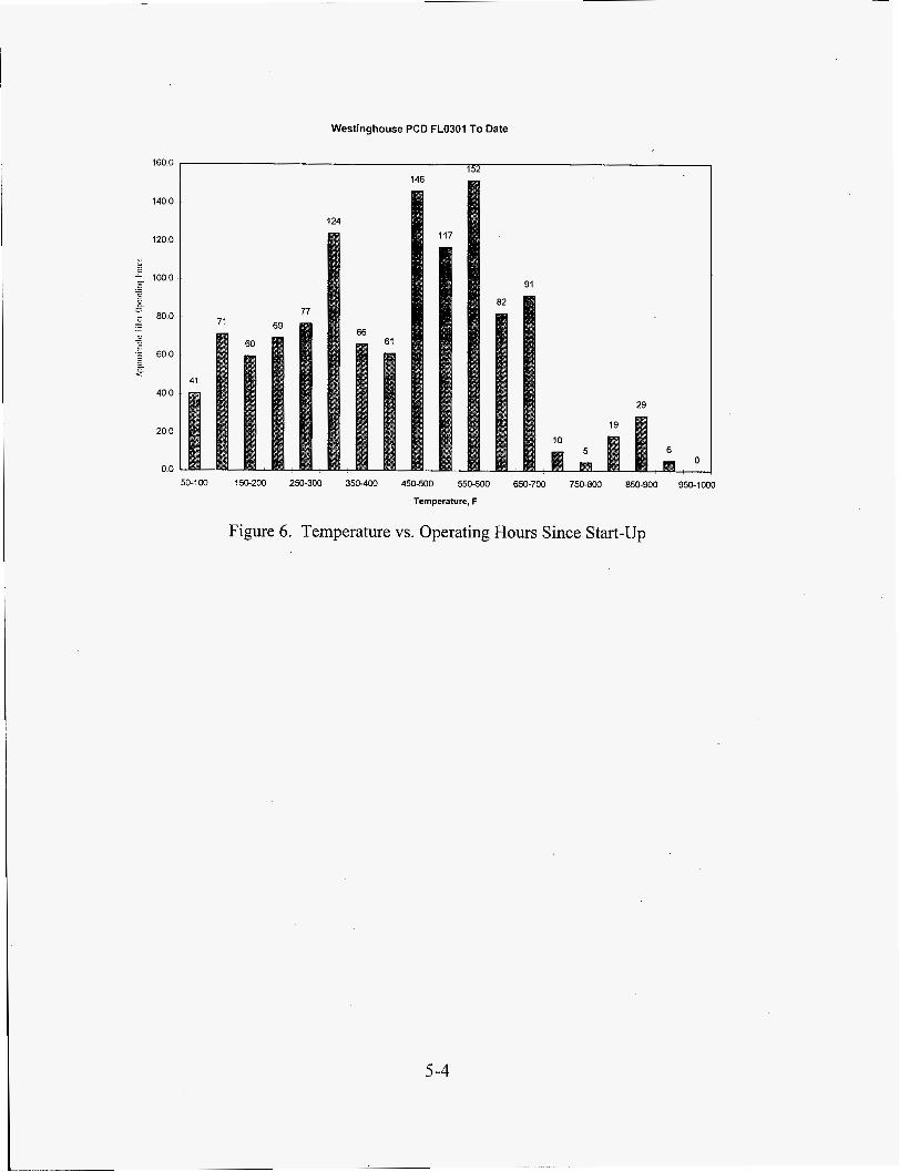
To date, the Westinghouse PCD has operated in combustion for 1226 hours (Figure 6). The PCD was filtering coal derived ash for about 275 of those 1226 hours.
Southern Research Institute (SRI) performed four sampling runs on the PCD inlet and outlet gas streams during the two combustion tests, CCT4A and CCT4B. Two inlet samples were collected with the bulk sampler and one of the inlet samples collected with the five-stage cyclone assembly. One outlet sample was taken using the bulk sampler. The results of these samples will be released in future reports.
During CCT2C in November 1996, SRI collected four samples at the PCD inlet. These samples were compared to the usual samples taken at the outlet of the ash removal system FD0520. From this data, it appears that there is a mechanical separation occurring in the PCD which distorts the particle size distribution of the samples taken from FD0520.
5 -2

SRI’s analysis of these samples in included in Appendix A of this report. This information seems to indicate that samples taken from the PCD cone would not be representative of the ash entering the PCD.
Westinghouse PCD FLOJOI lQ97 Operation
0
24 -1 24
18
0 0
6
50-100 150-200 250-300 350400 450-500 550-600 650-700 750-800 850-900 950-1000
Temperature, F
Figure 5. Temperature vs. Operating Hours For 1 st Quarter 1997
5-3
Westinghouse PCD FL030I To Date
160 0 152
71 69
60
77
124
66
146
117
61
40 0
20 0
00
02
91
29
50-100 150-200 250-300 350-400 450-500 550800 650-700 750-800 850-900 950-1M)O
Temperature, F
Figure 6. Temperature vs. Operating Hours Since Start-up
5-4
5.5 WESTINGHOUSE
During the first quarter of 1997, two additional thermocouples were added to the PCD cone to aid in determining ash level. The vessel, as supplied by Westinghouse, had three thermocouples in the cone for determining ash level. Two thermocouples were located just above the ash outlet and one at the top of the cone. The operational procedure calls for a transport reactor shutdown if the thermocouple at the top of the cone indicates that ash is present. Since this is a critical instrument, a backup thermocouple has been 'added at this elevation in an existing blind flange. The second thermocouple was added midway between the thermocouples at the top and bottom of the cone and installation required the addition of a new nozzle.
5.6 COMBUSTION POWER COMPANY (CPC)
CPC construction resumed in the quarter. Work will be completed by labor broker agreement with Caddell Construction who will be supervised by SCS Construction management. SCS personnel began preparing for construction by determining exactly what work was remaining, gathering materials and developing a detailed schedule for the remaining work. The remaining mechanical work is underway, and the electricalhnstrumentation installation will occur concurrently with the Foster Wheeler construction.
Electronic copies of all CPC drawings were received on site during the quarter. Additionally, the PLC has been delivered. SCS authorized the purchase of 3 mm media and CPC is currently looking for a supplier.
5.7 INDUSTRIAL FILTER AND PUMP (IF&P)
A letter was sent to IF&P during the first quarter which detailed a list of concerns generated by DOE and SCS. The concerns focused on the following:
Fibrosic filter element strength 0
0 Leakage ocfilter element seals 0 Maintainability
Reliability of failsafe system
Tubesheet to filter vessel seal
IF&P has written a response to the letter and had planned on visiting the jobsite in early April. This meeting has been delayed due to scheduling conflicts caused by testing, however, the meeting will occur as soon as possible.
5-5

5.8 SOUTHERN RESEARCH INSTITUTE
5.8.1 Particulate Sampling Systems
\
5.8.1.1 System Modifications and Improvements
Several minor modifications were made to the MWK Inlet sampling system this quarter to improve the sampling system operation. These modifications included:
0 Adding filters upstream of vent line solenoids to protect the valves from entrained ash. Moving the vents from the bottom of the ball valve casings to the top. Adding ball valves to isolate vent system so on-line maintenance could be performed. Adding equalization lines between the ball valves to prevent pressure/flow surges as the ball valves are opened.
0
0
0
These changes were replicated on the outlet sampling system as it was commissioned. Shakedown of the outlet sampling system occurred this quarter and was completed in March just prior to CCT4A.
5.8.1.2 Five-Stage Cyclone Sampler
Modifications were made to a conventional, five-stage cyclone sampler so that it could be connected to the sampling system. These modifications included shortening some of the interconnecting tubes and reorienting the cyclones to make the assembly as compact as possible. Under the operating conditions expected, the cut size should be from 7 to 9 pm for the first cyclone and 0.5 to 0.8 pm for the fifth cyclone.
The cyclone sampler contains a variety of screws and c-rings which were replaced with high temperature materials. A variety of coatings for the threads were investigated to minimize galling and ultimately it was decided to use Silver Goop TM on these connections. The cyclone sampler was used once at 700'F during CCT4 and none of the threaded connections showed any tendency to gall. This sampler is expected to be able to be used up to temperatures of 1200 OF.
c
5.8.1.3 Cyclone Manifold
The prototype cyclone manifold was delivered in February. The extensive weld repairs had caused distortion of some of the cyclone receptacles and interconnecting tubes. This manifold as well as the second casting has been sent to ThermoFab to determine whether or not they can perform the required machining on the second casting.
5-6
Contact has been made with Soligen to see if they can accurately cast the manifold. Soligen specializes in casting limited quantities of intricate metal components. The three dimensional CAD file of the manifold has been sent to Soligen for a cost estimate.
5.8.2 Evaluation Of Data
In addition to the analysis of data supporting the CCT2C test run which is in the appendix, SRI performed four sampling runs to evaluate particulate carryover to the PCD during the March testing. Two inlet samples were collected with the bulk sampler, one inlet sample was collected with the five-stage cyclone assembly, and one outlet sample was collected with the bulk sampler. The second inlet bulk sample was performed while the ash discharged from the PCD was collected in a drum. The objective of this test was to compare the particulate loadings determined by the sampling system and by collection of the discharged ash. However, the comparison was rendered invalid when a large quantity of ash was entrained from the combustion heat exchanger during the sample run.
The five-stage cyclone assembly was used for the first time during Run No. CCT4. No operational problems were encountered with the sampling system, but the coal feed to the reactor was cut off during the run, resulting in the collection of insufficient sample. The primary purpose of this first run was to test the durability of the cyclone sampler.
The outlet sampling system was also used for the first time during CCT4. Very little mass was collected in the bulk sampler during the four-hour run, suggesting that longer sampling times will be required to accurately determine the particulate loading leaving the PCD. The results of the CCT4 sampling runs are still being analyzed and will be discussed in detail in a future report.
5.9 FILTER ELEMENTS AND ELEMENT TESTING
5.9.1 Filter Elements Purchased
Several orders for filter elements were placed during the quarter. The current inventory of filter elements on site and on order is shown in Table 2. This list does not include the elements currently installed in the filter vessel.
5-7

Table 2. Filter Elements Being Ordered or in Inventory
Supplier Coors (Westinghouse) Fairey Microfiltrex
Pall Advanced Separations
Schumacher
3M
I
Type
316SS Inconel 601 Hastelioy HWC276 Type 442T Type 326 310SS Hastelloy X Iron Aluminide F20 T10-20 T05-20 Type 203
Quantity 40 5 5 5
92 18 5 5
‘ 5 20 20 20 20
Est. Delivery Date On Site June 1 June 1 June 1 On Site On Site May 1 May 1 May 1
April 22 April 22 April 22 On Site
5.9.2 Filter Element Testing
A cost estimate for testing filter elements was received from SRI. The estimate was based on performing 10 ring tensile tests on each filter element. The filters would be supplied to SRI in batches of 10 to minimize set up costs, etc. The cost of performing the testing is approximately $2,000 per filter element. Of that, $800 is the cost for machining the specimens.
One option being considered to minimize cost is to fabricate the tensile specimens at the PSDF and then ship them to SRI for evaluation. There are many advantages for fabricating the samples on site: uniformity of samples, providing samples for others to test, and the possibility of performing “round robin” testing at various labs. SRI has been helpful in identifying the equipment required for preparing the samples and has agreed to train PSDF personnel in the techniques they use. The equipment recommended was a Powermatic 20” Model 87 bandsaw and a KO. Lee 612 Surface Grinder. The total cost for these machines, in 1990, was $20,500.
5.10 MISCELLANEOUS
5.10.1 Training
In January, the operators were trained on a variety of systems including the PCD, ash removal and high-pressure aidnitrogen. The primary focus of the training was to discuss what had been learned during the first six months of operation and what changes would be made in the procedures as a result of the operating experience.
5 -‘8

6.0 AUXILIARIES AND BALANCE OF PLANT
6.1 FEEDSTOCK PREPARATION
The balance of plant transporters (FDO 104, coal, FDO 1 54, sorbent, and FDO 140, coke breeze and other solids) have functioned well. FD0140 material addition was modified to improve emptying a super sack to the FD0140 silo. The modification was made on March 12. Six thousand pounds of sand was added to FD02 10 storage bin on March 13 and transferred to the reactor. A total addition of 7 super sacks (21,000 lbs) was completed on March 14 and an additional 3000 lbs was added on the day shift of March 14 to FD0210.
6.2 PROCESS AIR
As previously reported, the main air compressor became unstable during cold weather but stability improved as the weather warmed. (It was during warm weather when the compressor was last tuned.) Atlas Copco, compressor vendor, stated that since the compressor tuning parameters were set in the summer for “summer air”(humidity -90% and temperature -90 OF), the compressor must be tuned again for the current conditions (humidity - 40% and temperature - 40°F). In the month of March stability could not be realized even in warm ambient conditions. Atlas-Copco was contacted and provided graphical data from the plant information (PI) data collection system. Temperature compensation logic was added to the program per the direction of an Atlas Copco technician, but stability still did not improve. Atlas-Copco sent another technician to re- tune the compressor and verify existing tuning constants, however little improvement was realized. Atlas-Copco’s engineering department is studying the problem prior to their return to the site, currently planned in April. Atlas Copco is concerned that the PSDF parametric testing requires the compressor to operate at multiple pressure/flow load points while the program was designed for only one point of operation. Nuisance alarms, generated from the main air compressor programmable logic controller (PLC) largely when the compressor is off-line, are another problem. Testing has revealed a periodic drop-out of all energized PLC outputs for 7- 15 milli-second every four minutes during cold weather. The period between drop-out events increases to every hour or more during warmer weather. Noise is suspected of being generated by cycling of the auxiliary oil pump (used to maintain oil temperature when the compressor is not running) and this noise could be interfering with the operation of the output card.
6.7 STEAMKONDENSATE
Due to low coal feed rates during all commissioning runs, the steam and condensate system operated below design conditions causing some problems. There was a persistent water hammer in the boiler feed water (BFW) line, because the BFW temperature did not
6- I
reach its setpoint and because the BFW was introduced into the vapor space of the drum. To solve this problem and the drum level control problems, a bypass line with modulating valve (FV406) was added to the liquid phase of the drum with a simple proportional integral derivative (PID) controller using drum level for the control variable. This will give better control at the low flow conditions found during combustion runs and also eliminate the water hammer that is present during such low flow.
6.10 FLARE
During the first quarter of 1997 the flare system was successfully commissioned. The purpose of the flare and its systems is to gather and ignite any spontaneous releases of combustible gases resulting from unit upsets or controlled depressurizing/purging of equipment. The flare system consists of a collection header, flare seal drum, flare tip, and flame front generator. The functional checks were initially completed in August 1996, but since some minor problems were found the checks were repeated in early February 1997. In early March the flare pilots were successfully lit and the enrichment gas flow was increased to evaluate the operations. The operations were found to be satisfactory.
6.17 AUXILIARY BOILER
The FW auxiliary boiler was started and tuned in February to support the low fire for boilout to remove oils and grease from the boiler tubing. After three days of firing for the boilout, the steam tubes were flushed and readied for normal operation. The boiler was then retuned for full pressure and load before blowing down the steam lines as the last stage of commissioning. The auxiliary boiler is now operational and lined up to provide steam to the propane vaporizer, and all other propane users on the project have been lined up using the high pressure propane from the vaporizer, in an effort to increase load on the vaporizer for better control of the vaporizer outlet pressure and temperature.
6-2

7.0 SUPPORT SERVICES
7.1 OPERATIONS AND MAINTENANCE
Refresher training was conducted on the MWK process for operators and staff personnel during January 1997. The primary focus of this training was familiarization with the operating procedures and changes that had been made in the various systems since the initial operator training. Following are the topics on which training was conducted:
Transport Reactor Particulate Control Device Main Air Compressor/Transport Air System Service/Instrument Air System Thermal Oxidizer Solids Transport Introduction to CoaUSorbent Preparation SteamKondensate System
In addition to the introduction to coal and sorbent preparation, a detailed operation course was conducted on the coahorbent preparation system for the Assistant Plant Control Operators. MWK process training was conducted for Maintenance personnel in March, including familiarization training on the various systems comprising the MWK process as well as systems supporting MWK operations. Required annual safety training was also performed at this time.
7.1.1 Maintenance Inspection and Procedures
During the outage this quarter, the Mechanics performed a number of activities including: repairing damaged valves, inspecting the transport reactor refractory and gas cooler vessels with the borescope, supporting preventive maintenance inspections of the MWK Process air compressor and the dense phase transport equipment, and replacing components on the SRI sampling probes to ready them for operation during the next combustion run. The mechanics also worked on preventive maintenance of the reactor by cleaning feeder lines, completing inspections of the transport reactor and PCD vessel, rebuilding valves on the instrument air dryers and supporting preventive maintenance work on the process air compressor. None of the these preventive maintenance inspections has uncovered any damage or area of concern; the refractory, PCD candles, and machinery were all in good shape during this outage. Summary results from specific equipment inspections are listed below.
The following equipment inspections occurred at the end of January
7- 1

Primary gas cooler (HX0202) - The top tube sheet of the primary gas cooler was inspected via nozzle AE-464 using the borescope. No mechanical problems or evidence of erosion were found. Two of the tubes are partially obstructed with what appears to be pieces of refractory. The restriction is not considered problematical to the operation of the heat exchanger, and no effort will be made at this time to remove them.
Riser / Disengager Crossover - The crossover was inspected with the borescope. No excessive erosion was seen, in particular, at the riser outlet. Some "lateral" erosion marks (parallel to the flow) were seen on the top of the crossover, but are not significant.
Burner J-leg - The burner J-leg was inspected with the borescope, and found to be clean. No other abnormalities were seen.
The sulfator vessel, SUO601 was inspected in February. All 76 fluidizing nozzles were probed and none were plugged. There were some small cracks in the refractory and a few loose pieces of thin refractory on the bottom of the vessel.
The 8" exit pipe on CY0201 was inspected. There was concern that the metal can deteriorate and allow bypassing of the vortex tube. No apparent holes were seen in the lower 14" metal section. Some dust was present so small holes would not be seen. The separation between the refractory above the metal pipe and the metal section was visible.
On March 25, sections of the reactor was inspected. Flanges were removed from A50, H1, Al , A52, A65, H2 and nozzle to orifice to inspect the reactor. The cyclone inlet was borescoped. There was some loss of refractory on the inlet tapered section but otherwise the narrowed inlet was intact. Also the cyclone was inspected from top where the refractory ends and the pipe starts and all sections were intact. Only light scale seemed to be present.
The orifice plate in the HX0202 bypass was inspected by borescope and no problems were noticed. The riser to standpipe crossover was about 1/3 full of sand. There were some grooves in the top. The riser had some small scale on the inside wall.
The standpipe had a small amount of scale. No sand level was detected 60 feet from the top. The disengager was also borescoped and there was not any accumulation present. Nozzle B on the cyclone was removed to inspect the radish, which was found to be clean.
7.2 LABORATORY
The lab staff was engaged in routine analytical work in support of the PSDF operation of the MWK reactor train. During the first quarter of 1997, 184 samples were logged into the PSDF laboratory. These included the following: 27 PCD solids samples; 3 MWK
7 -2

reactor solids samples; 26 MWK ash silo samples; 14 coal samples; 1 raw water sample; 30 cooling tower water samples; 1 cooling tower blowdown samples; 7 MWK circulating cooling water samples; 13 SCS circulating cooling water samples; 10 boiler condensate samples; 4 wastewater treatment plant effluent samples; 10 wastewater samples; 3 thermal oxidizer burner samples; 5 stormwater runoff samples; 1 solid waste sample; 1 isokinetically collected particulate sample; 10 PSDF sanitary effluent samples; and 18 miscellaneous samples (ash, sand, UCONN heat transfer fluid, charcoal, etc.).
Fifty-three samples were submitted to the off-site laboratory for analysis and the remainder were analyzed in the PSDF laboratory. The off-site lab performed ash minerals analyses, coal proximate and ultimate analyses, polyaromatic hydrocarbons analyses, TCLP metals analyses, wear metals analyses, and trace metals analyses. Cooling water analyses, sieve analyses, Microtrac particle size analyses, as-received loss- on-ignition analyses, and bulk density analyses were performed by the PSDF lab staff. There were 14 17 total analyses performed with the 184 samples.
Specifications for an amperometric titrator capable of measuring the free chlorine concentration (1 1 ppb) designated in the PSDF NPDES permit were determined. These specifications include a digital current readout, a digital titrator, and a back-titration kit to measure the low chlorine levels in the cooling tower blowdown flow. After bid solicitation, an amperometric titrator with back-titration kit was ordered for analysis of circulating cooling water blowdown samples. The amperometric titrator with back- titration kit for analysis of blowdown chlorine concentration was received during March. The unit was set up for the forward titration with phenylarsine oxide (PAO) and achieved a detection limit of 13 pg/L (ppb). Attempts to perform the back titration with potassium iodide were not successful. The problem appears to result from reagent deterioration and a fresh supply has been ordered and the performance of the back-titration unit will be
' validated during April. The back titration procedure is expected to yield a detection limit near 5 pg/L.
7.3 DATA MANAGEMENT
The point by point security for the current 1500 tags in the plant information (PI) data management system was established. Potential improvements in PI backup plans were discussed and implemention of ideas was begun. The trial evaluation period for PI is nearly over and the license agreement preparation and negotiations are underway.
7.4 ENVIRONMENTAL .
The fourth quarter 1996 NPDES Discharge Monitoring report was submitted to the Alabama Department of Environmental Management (ADEM) on January 2 1 , 1997. Also, a fourth quarter 1996 Air Emission Summary Report was submitted to ADEM on January 28. The SARA Tier I1 report was submitted to ADEM, the Shelby County Emergency Management, and the Wilsonville Fire Department on February 25.
7-3

7.5 SAFETY
No lost-time injuries were recorded for the first quarter in 1997. Safety topics covered in monthly meetings included the Hazard Communication Standard and Hearing Conservation. The new year was begun with safety training in Confined Space and Lockout and Tagout. The OSHA 200 log, summarizing the 1996 safety record, was posted February 1, and removed March 1, as required by federal law.
7-4

8.0 PROJECT MANAGEMENT
Date 01/13/97
The Cooperative Agreement for the Power Systems Development Facility, DE-FC2 1 - 90MC25 140, between Southern Company Services and the United States Department of Energy was scheduled to expire on March 13, 1997, at the end of Budget Period 5. However, a no cost contract extension was approved to extend the current agreement through May 3 1, 1997. Negotiations are ongoing to finalize approval of the Request for Contract Renewal (RCR) and the authorizationlobligation of the funding of the Cooperative Agreement for Budget Period 6. An application has been submitted to DOE requesting authorizationlobligation of the April 1997 funds that were identified in the RCR. Current projections are that the renewal of the RCR and sluthorization/obligation of funds for Budget Period 6 will approved in May 1997. The scope of Budget Periods #6 and #7 will include the following: (1) completion of the construction phase of the Advanced Pressurized Fluidized Bed Combustion Module (APFBC) which includes Foster Wheeler’s technology for second generation Pressurized Fluidized Bed Combustion (PFBC), associated Particulate Control Devices (PCDs), the Compressor/Turbine Module, related Balance of Plant facilities, and the startup of these modules; and (2) the continued operation and testing of the Advanced Gasifier Module which involves M. W. Kellogg’s transport reactor, associated Particulate Control Devices and related Balance of Plant facilities. Budget Periods #7 through #10 will cover the operation and testing of these modules plus the operation and testing of the Fuel Cell Module. ‘
Group Purpose Officials from the United Kingdom PSDF Site Visit
The drafting of a commissioning report detailing the start-up events and process test runs for the entire year of 1996 was begun during this quarter. The major meetings held at PSDF during this quarter are summarized in Table 3.
01/13/97 01/22/97
02/10/97 02/13/97 03/04/97
03/07/97 03/12/97
0311 3/97
Table 3. .Roster Of PSDF Meetings
Center for Coal Utilization, Japan Visit Wilsonville APFBC EAD Staff Meeting Environmental Assessment (Bryan Baldwin) Department Staff Meeting FW Hard Dollar Contract Meeting FW Hard Dollar Contract Meeting Chuck Griffin, Rob Minter - SCS Public Relations EDF (Electricity deFrance) Gasification Users Association (EPRI, DOE, FW, MWK, W) Coal and Railroad Industry R.eps., DOE, SCS Fuels Visit
FW Hard Dollar Contract Meeting FW Hard Dollar Contract Meeting SCS Public Relations Site Tour
EDF Site Visit/Tour GUA Meeting and PSDF Site Visit
Coal and Railroad Industry Site
8- 1

9.0 FUTURE PLANS
The next combustion run on the transport reactor is scheduled to start in early April, and another run is scheduled in May before making the required changes in order to operate the transport reactor as a gasifier. There are several issues still to be resolved prior to gasification operation, including some modifications currently underway to the MWK Sulfator. Shake-down of the transport reactor as a gasifier is projected to begin late during the summer of 1997.
During the second quarter of 1997, the technical specifications and drawings for the FW fixed price contract are to be finalized. An agreement should be implemented with the low cost fixed price bidder (“Contractor”) for construction and construction should begin, including planning/scheduling with the Contractor to mesh construction and operation schedules. Installation of foundations should continue, utilizing the Labor Broker.
Planning for start-up of the FW equipment will continue in the next quarter. This effort will be balanced with the requirements for on-going operation of the MWK transport reactor as both a combustor and as a gasifier. FW operating and commissioning procedures will be reviewed and revised, training materials for operations personnel will be prepared, and manpower requirements to support start-up will be reexamined. Start-up of the FW combustion turbine, MASB, and related auxiliary equipment is currently projected for the fall of 1997.
9- 1

APPENDIX A
SRI’s ANALYSIS OF CCT2C SAMPLES
A- 1
SRI'S ANALYSIS OF CCT2C SAMPLES
Run No.
INTRODUCTION
~ ~~
MWKIMT-1 MWKIMT-2
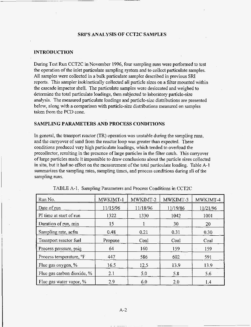
During Test Run CCT2C in November 1996, four sampling runs were performed to test the operation of the inlet particulate sampling system and to collect particulate samples. All samples were collected in a bulk particulate sampler described in previous SRI reports. This sampler isokinetically collected all particle sizes on a filter mounted within the cascade impactor shell. The particulate samples were desiccated and weighed to determine the total particulate loadings, then subjected to laboratory particle-size analysis. The measured particulate loadings and particle-size distributions are presented below, along with a comparison with particle-size distributions measured on samples taken from the PCD cone.
MWKIMT-3
11/19/86 1042
30 0.3 1 Coal 159 602
13.9 5.8
2.0
SAMPLING PARAMETERS AND PROCESS CONDITIONS
MWKIMT-4
11/21/96 1001 20
0.30 Coal
159 591
13.9 5.6
1.4
In general, the transport reactor (TR) operation was unstable during the sampling runs, and the carryover of sand from the reactor loop was greater than expected. These conditions produced very high particulate loadings, which tended to overload the precollector, resulting in the presence of large particles in the filter catch. This carryover of large particles made it impossible to draw conclusions about the particle sizes collected in situ, but it had no effect on the measurement of the total particulate loading. Table A-1 summarizes the sampling rates, sampling times, and process conditions during all of the sampling runs.
Date of run PI time at start of run
TABLE A-1 . Sampling Parameters and Process Conditions in CCT2C
11/15/96 11/18/96 1322 1330
Duration of run, min Samuling rate. acfm
15 1 0.48 0.21
Transport reactor fuel Propane Coal ' Process uressure. mig. 64 160
A-2
Process temperature, OF
Flue gas oxygen,,%
Flue gas carbon dioxide, %
Flue gas water vapor, %
447 586 16.5 12.5
2.1 5.0 2.9 6.0

MEASURED PARTICULATE LOADINGS
The measured particulate loadings are summarized in Table A-2. The loadings generally exceeded the PCD design loadings, but the decrease in loading throughout the test reflected the success of various efforts to reduce the loss of bed material from the transport reactor. It should be noted that the transport reactor was being fired with propane during the first run, so the particulate matter collected reflects the bed material that was carried out of the transport reactor.
The measured particulate loadings could not be rigorously compared to the loadings determined from the rate of ash discharge from the PCD cone. However, estimates made from the ash removal system performance suggested that the measured particulate loadings were reasonable.
TABLE A-2. Measured Particulate Loadings
MWKIMT-3 12.145 MWKIMT-4 15,808 I
PARTICLE-SIZE ANALYSIS
The in-situ particulate samples were subjected to laboratory particle-size analysis along with samples collected from the PCD cone during roughly the same time intervals. The size measurements were made using a combination of sieves and a Leeds and Northrup Microtrac X-1 00 particle-size analyzer, although a few samples were measured with only the Microtrac. The sieves were used to remove and size segregate the largest particle fractions, while the Microtrac measured the distribution of finer particles that fell through the last sieve. The Microtrac could not be used alone when large quantities of sand were present in the samples, because of settling problems with the larger particles.
Figure A-1 shows the composite size distribution resulting from the combination of the sieve and Microtrac measurements on one of the in-situ samples. In this case, the sieve measurement (open circles) included seven size cuts from 30 to 120 mesh corresponding to particle sizes from 600 to 125 pm. The Microtrac data for the particles that passed through the last sieve (nominally smaller than 125 pm) is represented by the open squares. The dashed lines on the figure are extrapolations of the slopes of the last two data points of each measurement system’s range. The difference in slope where the two
A-3

data sets coincide indicates that there are some problems with this method of producing a composite distribution. This will be evaluated further below.
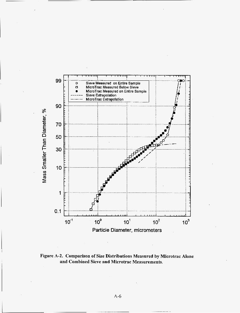
Since the sample shown in Figure A-1 did not contain an excessively high concentration of sand or other large particles, a portion of it was run through the Microtrac without sieving. These results are compared to the composite size distribution in Figure A-2 and indicate fairly good agreement between the general shape of the Microtrac and composite distributions. However, the median particle sizes obtained from the two distributions are different by a factor of two (125 pm for Microtrac versus 250 pm for the composite). The Microtrac-only distribution also suggests that the dip in the composite distribution at the intersection of the two measurement systems may be artificially induced.
Figure A-3 compares the two Microtrac measurements (entire distribution and minus 120 mesh) on a differential mass basis rather than cumulative percentage basis. Viewed in this way, the problem with the composite distribution becomes obvious. Based on the Microtrac analysis, the sieve is undercutting its rated size of 125 pm and removing particles all the way down to 20 pm. The reduced concentration of particles in the 20- to 125-pm range leaving the sieve is responsible for the dip in the composite distribution. However, this does not necessarily indicate a problem with the sieve measurement, but could be related to differences in the characteristics of the two measurements.
The size data measured on all four of the in-situ samples are shown in Figures A-4 and A-5 as cumulative percentage and cumulative mass distributions, respectively. These data illustrate the change in size distribution during the period of the combustor run. On November 15, 1996, the combustor was operating on propane with only sand circulating in the reactor loop. The in-situ sample collected at the PCD inlet on that date (MWKIMT-1) shows a coarse size distribution. The other three samples were obtained during coal combustion and indicate concentrations of fine flyash particles two orders of magnitude higher than with sand alone. The sample on November 18, indicated that carryover of bed material was still higher than desired, while by November 19, conditions had stabilized with lower carryover.
Dust samples were collected from the PCD cone several times each day of the coal combustion run. Size distributions measured on selected PCD cone samples spread over the test period are compared with one of the in-situ samples in Figure A-6. The cone samples collected before coal combustion began would be expected to be very coarse. However, with one exception, all of the cone samples are dominated by large particles and have a much coarser size distribution than indicated by the in-situ samples. This may be caused by the immediate and continuous gravitational settling of large particles into the PCD cone while the small particles that are initially collected on the filters fall into the cone only after a cleaning pulse. This segregation of particle sizes by the PCD would make obtaining a representative cone sample of the inlet dust very difficult.
A-4

1 99.99
99.9
0 Sieve Measured 0 MicroTrac Measured
Sieve Extrapolation MT ExtraDolation
-__-__ -.-.-
L
._____
90 ggl 1
0.1
:.
-.
-
I I I I I l l , , I I I l I l ( 1
..........................................................................
..........................................................................
................................... : .....................................
I i ........................ a ....... i ......................................
I I , , I I I I ,'A
- ..................................
........... .......... fl 0
0
I 1 1 1 1
..........................
............................
............................
..................... 0""' 1
............................
......... p I ...............
&--
............................. - lo-' 1 oo I O ' 1 o2
Particle Diameter, micrometers 1 o3
Figure A-1. PCD Inlet Particle Size Distribution from Combined Sieve and Microtrac X-100 Measurements on In-Situ Sample MWKIMT-3.
A-5
I 1 I I 1 1 1 1 1 1 I I I I I I , l I I I I I I l l
gg ...... Sieve Measured on Entire Sample MicroTrac Measured Below Sieve MicroTrac Measured on Entire Sample
90
70
50
30
10
1
........................................ 1:
........................................
........................................ i 0.1
lo-’
IC Extrapolation
...................................
...................................
r
I
.................................. -
- 0. ........................... p I
i i‘ ..................... 7 .......
..............................
...... ...................
cf E----
- 1 oo IO’ 1 o2
Particle Diameter, micrometers 1 o3
Figure A-2. Comparison of Size Distributions Measured by Microtrac Alone and Combined Sieve and Microtrac Measurements.
A-6

I I 1 1 1 1 1 1 I I I I I l l
........................... Entire Sample I
0 Minus 120M1
................................
0 s lo-’
.................................. -
..............
.O
- ...................................
................................ ’@I i
0
1 oo IO’ 1 o2 Particle Diameter, micrometers
1 o3
Figure A-3. Comparison of Microtrac Measured Size Distributions for Complete Sample and Particles Smaller than 120 Mesh.
A-7

99.9
99
90
70
50
30
10
1
0.1
0.01 ~
1 oo 10’ 1 o2 1 o3 Particle Diameter, micrometers
Figure A-4. Comparison of Cumulative Percent Particle Size Distributions for All Isokinetically Collected Samples.
A-8

c m e
A MWKI-2MT, 11/18/9f MWKI-BMT, 11/19/9f + MWKMMT, 11/21/9(
1 o3
1 o2
I O ’
I I I I I I l l I I I I I I I I
................................................................................................
.................................................................................................
1 oo I O ’ 1 o2 Particle Diameter, micrometers
1 o3
Figure A-5. Comparison of Cumulative Mass Size Distribution for All Isokinetically Collected Samples.
A-9

I I I I 1 1 1 1 1 I I I I I 1 1 1
............................................
A AB00513, 11/15/96 AB00516, 11/16/96
+ AB00522, 1111 8/96 V AB00553, 11/20/96
............................................
.................................................. 70 L..; ................................................... i - E i 4 :
50
30
10
1
I I I 1 1 1 1 1
-
................................................. :..-
0.1 -..i ....................................................................................................................................................... ;..
I I I I I I I , , I I I 1 I I I , I I I 1 , , , ,
1 oo 10’ 1 o2 1 o3 Particle Diameter, micrometers
Figure A-6. Comparison of Size Distributions from PCD Inlet In-Situ Sample and PCD Cone Samples.
A-10

M97053936 111ll1111 Ill lllll11111111Il111111111111111 Ill11 1111 1111
Report Number (14) m1& c 1.2- S I ya - -
'ubi. Date (11) ISS7Q'l Sponsor Code (18) 'J3&@Fk ' . ; X I = * J C Category (1 9) c/o c, -101; 0 b i q k k
DOE