power take-offs - ibb.iveco.comibb.iveco.com/body builder instructions/north europe and...
TRANSCRIPT
POWER TAKE-OFFS 4-1EUROCARGO M.Y. 2008
Print 603.95.003 Base - January 2009
Index
Index
SECTION 4
Power take-offs
Page
4.1 General Specifications 4-3
4.2 Power take-off from gearbox 4-5
4.3 Power take-off from the transfer box 4-8
4.4 Power take-off from transmission 4-8
4.5 Power take-off from engine 4-9
4.5.1 Taking torque from engine front side 4-9
4.5.2 Power take off from the rear of the engine 4-11
4.6 PTO management 4-13
4.6.1 General specifications 4-13
4.6.2 PTO Mode 0 (run mode) 4-14
4.6.3 PTO modes 1, 2, 3 configurable 4-14
4.6.4 Intermediate speed rate governor 4-18
4.6.5 Standard configurations 4-19
4.6.6 Specific indications: correlation between PTO configuration and power take-offs installed 4-20
4.6.7 Power take-off depending on the clutch 4-20
4.6.8 Second speed limiter 4.23
4.7 Electrical system 4-24
4.8 Pneumatic system 4-24
4.9 Isochronous control of engine rate 4-24

4-2 POWER TAKE-OFFS EUROCARGO M.Y. 2008
Base - January 2009 Print 603.95.003
Index
POWER TAKE-OFFS 4-3EUROCARGO M.Y. 2008
Print 603.95.003 Base - January 2009
General Specifications
44444.
General Specifications
4.1 General Specifications
Different types of power takeoffs can be used dependine on the type of use and the performances required, the PTO can befitted to:- the gearbox.
- driveline.
- the front of the engine.
- the rear of the engine.
The characteristics and performances are given in the paragraphs which follow and in the relevant documentation which will besupplied upon request.
For the definition of the power necessary for the apparatus to be controlled, particularly when the values requested are high, theabsorbed power should also be considered during the drive transmission phase (5 to 10% for the mechanical transmissions, beltsand gears, and greater values for the hydraulic controls).The choice of transmission ratio for the power take-off should be made so that the absorption of power occurs in a flexible engineoperating range. Low r.p.m. (below 1000 r .p.m.) must be avoided to prevent irregular running.
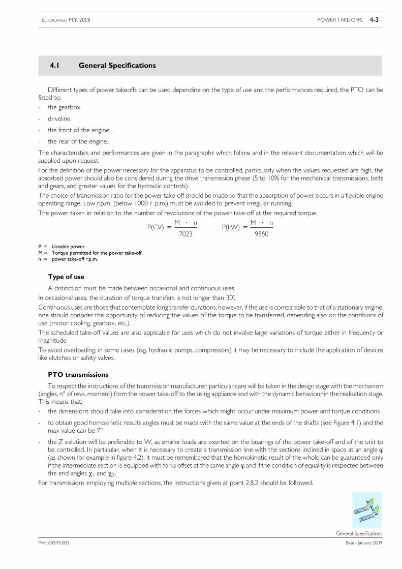
The power taken in relation to the number of revolutions of the power take-off at the required torque.
P(CV)= M ⋅ n
7023P(kW)= M ⋅ n
9550
P = Useable powerM = Torque permitted for the power take-offn = power take-off r.p.m.
Type of use
A distinction must be made between occasional and continuous uses.In occasional uses, the duration of torque transfers is not longer than 30’.Continuous uses are those that contemplate long transfer durations; however, if the use is comparable to that of a stationary engine,one should consider the opportunity of reducing the values of the torque to be transferred, depending also on the conditions ofuse (motor cooling, gearbox, etc.).The scheduled take-off values are also applicable for uses which do not involve large variations of torque either in frequency ormagnitude.To avoid overloading, in some cases (e.g. hydraulic pumps, compressors) it may be necessary to include the application of deviceslike clutches or safety valves.
PTO transmissions
To respect the instructions of the transmission manufacturer, particular care will be taken in the design stagewith themechanism(angles, n° of revs, moment) from the power take-off to the using appliance and with the dynamic behaviour in the realisation stage.This means that:- the dimensions should take into consideration the forces which might occur under maximum power and torque conditions
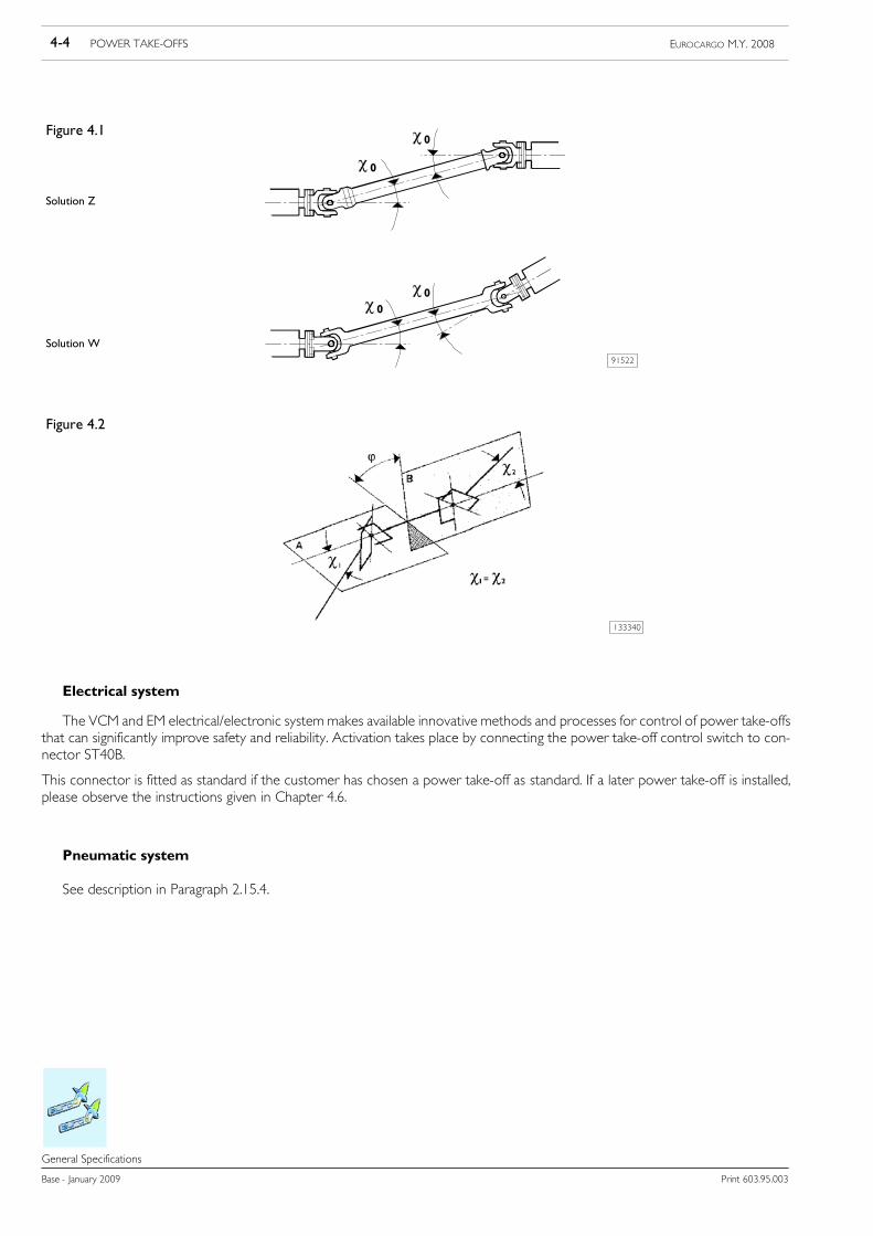
- to obtain good homokinetic results angles must be made with the same value at the ends of the shafts (see Figure 4.1) and themax value can be 7”
- the Z solution will be preferable to W, as smaller loads are exerted on the bearings of the power take-off and of the unit tobe controlled. In particular, when it is necessary to create a transmission line with the sections inclined in space at an angle ϕ(as shown for example in figure 4.2), it must be remembered that the homokinetic result of the whole can be guaranteed onlyif the intermediate section is equipped with forks offset at the same angle ϕ and if the condition of equality is respected betweenthe end angles χ1 and χ2.
For transmissions employing multiple sections, the instructions given at point 2.8.2 should be followed.
4-4 POWER TAKE-OFFS EUROCARGO M.Y. 2008
Base - January 2009 Print 603.95.003
General Specifications
Solution Z
Solution W91522
Figure 4.1
0
0
00
Figure 4.2
133340
Electrical system
The VCM and EM electrical/electronic system makes available innovative methods and processes for control of power take-offsthat can significantly improve safety and reliability. Activation takes place by connecting the power take-off control switch to con-nector ST40B.
This connector is fitted as standard if the customer has chosen a power take-off as standard. If a later power take-off is installed,please observe the instructions given in Chapter 4.6.
Pneumatic system
See description in Paragraph 2.15.4.
POWER TAKE-OFFS 4-5EUROCARGO M.Y. 2008
Print 603.95.003 Base - January 2009
Power Take-off from Gearbox
Power Take---off from Gearbox
4.2 Power take-off from gearbox
Depending on the type of gearbox power can be taken from the layshaft through the flange or spline located on the rear, sideor lower part of the gearbox.
The technical characteristics necessary are given in the documentation supplied upon request for the various gearboxes.
The types of power take-off and the torque values obtained with the ratio between the number of output revolutions and enginer.p.m. are shown in Table 4.1.
The values refer to the conditions indicated in the table.
Higher values for occasional use must be agreed upon as each occasion arises depending on the type of use.
Check the vehicle to ascertain whether it is possible to fit a power take-off suitable to its size.
The power take-off applied to the gearbox must only be used when the vehicle is stationary and must be engaged and disengagedwhen the clutch is disengaged to avoid excessive stress on the synchronisers during gear change. For special situations when thepower take-off is used and the vehicle is moving the gear must not be changed.
For gearboxes equipped with a torque converter, the same power take- offs used for normal gearboxes are, as a rule, used. It shouldbe carefully noted that, when the engine r.p.m. is below 60% of the max. value the converter will be in the phase of hydraulic r.p.m.;in this phase, depending on the absorbed power, the r.p.m. of the power take-off is subject to oscillation despite the fact that theengine r.p.m. is constant.
Direct Application of Pumps
When the application of pumps of other equipment (e.g. for tippers or cranes) is carried out directly from the power take-off,without the use of intermediate shafts and after checking that the size of the pump permits margins of safety with chassis and engineunit (cross member, transmission shaft etc.), the static and dynamic torques exerted by the mass of the pump and by the powertake-off should be checked for compatibility with the resistance of the walls of the gearbox. By way of an example, the momentdue to the additional masses must not have values of over 3% approx. of the maximum engine torque.
In cases where the gearbox is applied in a single unit with the engine, the value of the additional masses must be verified with regardto the inertial effects in order to avoid the induction of resonance conditions in the engine unit within the field of operational engi-ne r.p.m.
!When fitting power take-offs the torque values shown in Table 4.1 must not be exceeded.Transmission oil temperature must not exceed 120ºC during prolonged use. Coolant temperaturemust not exceed 100°C.Not all types of power take-off available on the market are suitable for continuous use. When in usethe specifications (working periods, pauses etc.) specific to the power take-off in question should berespected.
4-6 POWER TAKE-OFFS EUROCARGO M.Y. 2008
Base - January 2009 Print 603.95.003
Power Take-off from Gearbox
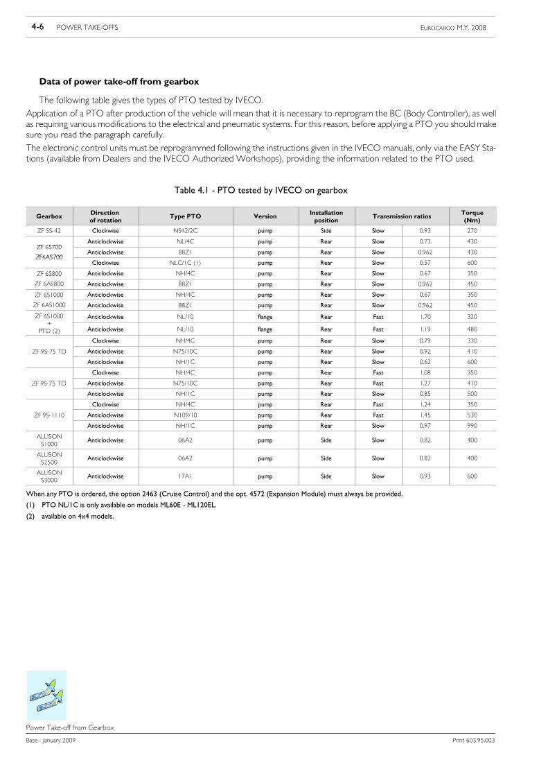
Data of power take-off from gearbox
The following table gives the types of PTO tested by IVECO.
Application of a PTO after production of the vehicle will mean that it is necessary to reprogram the BC (Body Controller), as wellas requiring various modifications to the electrical and pneumatic systems. For this reason, before applying a PTO you should makesure you read the paragraph carefully.
The electronic control units must be reprogrammed following the instructions given in the IVECO manuals, only via the EASY Sta-tions (available from Dealers and the IVECO Authorized Workshops), providing the information related to the PTO used.
Table 4.1 - PTO tested by IVECO on gearbox
Gearbox Directionof rotation
Type PTO Version Installationposition
Transmission ratios Torque(Nm)
ZF SS-42 Clockwise NS42/2C pump Side Slow 0.93 270
ZF 6S700Anticlockwise NL/4C pump Rear Slow 0.73 430
ZF 6S700
ZF6AS700Anticlockwise 88Z1 pump Rear Slow 0.962 430
ZF6AS700Clockwise NLC/1C (1) pump Rear Slow 0.57 600
ZF 6S800 Anticlockwise NH/4C pump Rear Slow 0.67 3506S800
ZF 6AS800 Anticlockwise 88Z1 pump Rear Slow 0.962 450
ZF 6S1000 Anticlockwise NH/4C pump Rear Slow 0.67 3506S 000
ZF 6AS1000 Anticlockwise 88Z1 pump Rear Slow 0.962 450
ZF 6S1000+
Anticlockwise NL/10 flange Rear Fast 1.70 320+
PTO (2) Anticlockwise NL/10 flange Rear Fast 1.19 480
Clockwise NH/4C pump Rear Slow 0.79 330
ZF 9S-75 TD Anticlockwise N75/10C pump Rear Slow 0.92 4109S 75
Anticlockwise NH/1C pump Rear Slow 0.62 600
Clockwise NH/4C pump Rear Fast 1.08 350
ZF 9S-75 TO Anticlockwise N75/10C pump Rear Fast 1.27 4109S 75 O
Anticlockwise NH/1C pump Rear Slow 0.85 500
Clockwise NH/4C pump Rear Fast 1.24 350
ZF 9S-1110 Anticlockwise N109/10 pump Rear Fast 1.45 5309S 0
Anticlockwise NH/1C pump Rear Slow 0.97 990
ALLISONS1000
Anticlockwise 06A2 pump Side Slow 0.82 400
ALLISONS2500
Anticlockwise 06A2 pump Side Slow 0.82 400
ALLISONS3000
Anticlockwise 17A1 pump Side Slow 0.93 600
When any PTO is ordered, the option 2463 (Cruise Control) and the opt. 4572 (Expansion Module) must always be provided.
(1) PTO NL/1C is only available on models ML60E - ML120EL.
(2) available on 4x4 models.
POWER TAKE-OFFS 4-7EUROCARGO M.Y. 2008
Print 603.95.003 Base - January 2009
Power Take-off from Gearbox
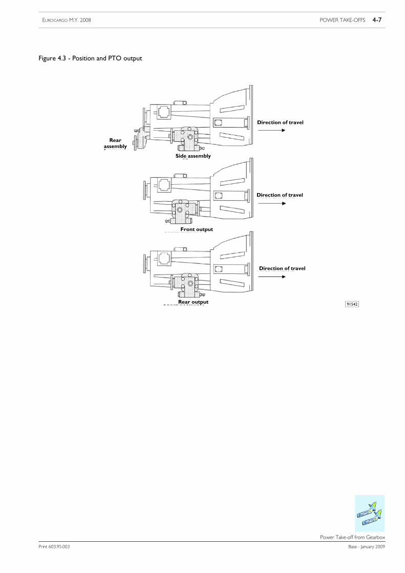
Figure 4.3 - Position and PTO output
91542
Rearassembly
Side assembly
Direction of travel
Direction of travel
Direction of travel
Front output
Rear output
4-8 POWER TAKE-OFFS EUROCARGO M.Y. 2008
Base - January 2009 Print 603.95.003
Power take-off from the transfer box
Power take---off from the transfer box
4.3 Power take-off from the transfer box
For four-wheel drive vehicles (4x4), it is possible to apply power take-offs to the torque distributor.The application r.p.m. can be selected according to the required function by engaging the most appropriate gear.
Use is only with the vehicle stationary (transfer box in neutral). The prescriptions on correct use are given in the vehicle’s Use andMaintenance booklet.
There follow the possible measurements:
Table 4.2
Power take-off
Type of transfer box PTO Max. capacity(Nm) Output type
TC 850 Only types tested by IVECO 500ext. diameter flange 90 mm4 holes diameter 8.1 mm
4.4 Power take-off from transmission
Authorisation to fit a power take-off on the transmission downstream of the gearbox will be issued after examination of thefull documentation, which must be presented to IVECO.
The various power and torque values will be evaluated as each occasion arises on the basis of the conditions of use.
In general the following should be noted:
- the drive take-off may be operated only when the vehicle is stationary.
- the power take-off r.p.m. is tied to the gear selected.
- the power take-off must be located immediately downstream of the gearbox. For vehicles with the transmission in two or moresec tions, the power take-off may also be applied at the site of the flexible support included between the first and second sections(respect the indications given in point 2.8.8).
- the angles of the transmission on the horizontal plane and vertical plane must be kept as close as possible to the original values.
- masses and rigidity added to the transmission must not provoke a loss of balance or abnormal vibrations or damage to the organsof the drive transmission (from engine to axle) either during vehicle movement or during operation with the motor running
- the power take-off must be anchored to the chassis with its own suspension.
!As the transmission is is an important organ for the safety of the vehicle, modification to it must onlybe carried out by specialist companies approved by the supplier of the transmission.
POWER TAKE-OFFS 4-9EUROCARGO M.Y. 2008
Print 603.95.003 Base - January 2009
Power take-off from engine
Power take---off from engine
4.5 Power take-off from engine
In general the use of these power take-offs is planned for apparatus requiring a continuous power supply.
4.5.1 Taking torque from engine front side
The drive take-off from the front part of the crankshaft is obtained, for limited power values to be drawn off (e.g. conditioninggroup commands) by the drive belt transmission, the use of cardan shafts is normally reserved for take-offs of a greater m agnitude(e.g. municipal use).
These uses, when not specifically planned, require complicated interventions to the front part of the vehicle, e.g. modifications tothe radiator, cab, bumpers etc. Part icular attention must therefore be paid:
- to the system composed of additional masses and relative rigidity which must be flexibly disengaged from the crankshaft withregard to the torsional and flexional effects;
- to the additional mass values and relative moments of inertia and to the distance from the centre of gravity of the masses fromthe centreline of the first main bearing which must be contained as much as possible;
- to avoiding a reduction in the radiator cooling capacity;
- to restoring the rigidity and resistance characteristics of the modified elements (cross member, bumper etc.);
- to avoid exceeding, during extended use, temperatures of the engine cooling fluid of over 100 °C and engine oil temperature(measured on the main duct of the pressure switch area) of 120 °C. A margin of approx. 10% should however be left. In othercases include supplementary heat exchangers.
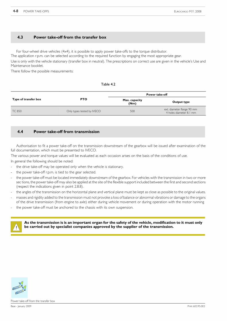
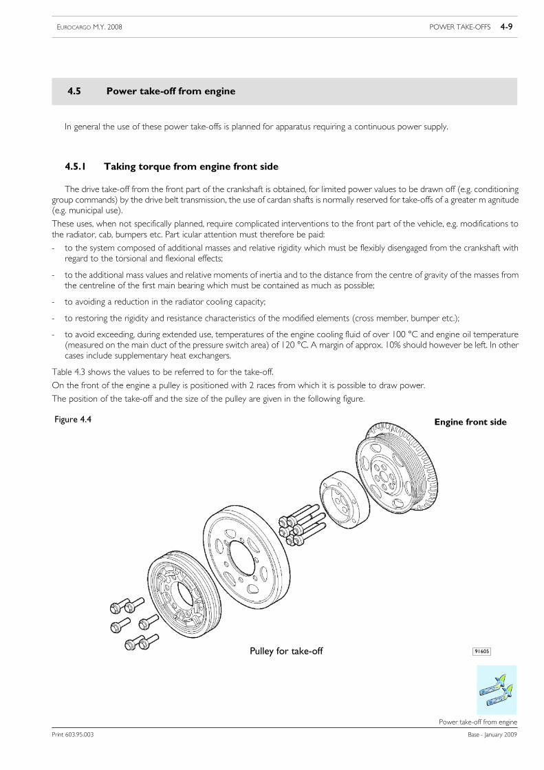
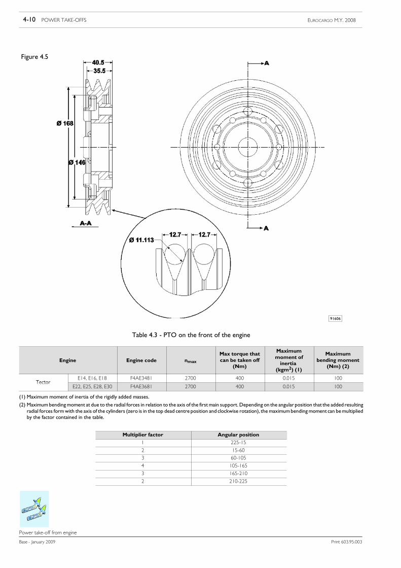
Table 4.3 shows the values to be referred to for the take-off.
On the front of the engine a pulley is positioned with 2 races from which it is possible to draw power.
The position of the take-off and the size of the pulley are given in the following figure.
Figure 4.4
Pulley for take-off
Engine front side
91605
4-10 POWER TAKE-OFFS EUROCARGO M.Y. 2008
Base - January 2009 Print 603.95.003
Power take-off from engine
Figure 4.5
91606
Table 4.3 - PTO on the front of the engine
Engine Engine code nmaxMax torque thatcan be taken off
(Nm)
Maximummoment ofinertia
(kgm2) (1)
Maximumbending moment
(Nm) (2)
TectorE14, E16, E18 F4AE3481 2700 400 0.015 100
TectorE22, E25, E28, E30 F4AE3681 2700 400 0.015 100
(1) Maximum moment of inertia of the rigidly added masses.
(2) Maximumbendingmoment at due to the radial forces in relation to the axis of the first main support. Depending on the angular position that the added resultingradial forces formwith the axis of the cylinders (zero is in the top dead centre position and clockwise rotation), the maximumbendingmoment can bemultipliedby the factor contained in the table.
Multiplier factor Angular position
1 225-15
2 15-60
3 60-105
4 105-165
3 165-210
2 210-225

POWER TAKE-OFFS 4-11EUROCARGO M.Y. 2008
Print 603.95.003 Base - January 2009
Power take-off from engine
4.5.2 Power take off from the rear of the engine
4.5.2.1 Multipower power take-off on flywheel side
On models 150E ÷ 190EL with powers of 280 to 300 BHP, the IVECO Multipower, designed to take off higher torques thanthose of other PTOs power take-off can be installed on request. This unit is fitted on the rear part of the engine (Figure 4.3) andtakes drive from the flywheel. It is independent of the vehicle clutch drive and suitable for use with the vehicle running and/or ata standstill (e.g. municipal applications, concrete mixers, etc.).
Some precautions:- the PTO must be engaged only with the engine at a standstill (a safety device prevents engagement with the engine runningin any case);
- the unit may be disengaged with the engine running but only if power is not currently being taken off;
- the engine must be started when no torque is being taken from the PTO.
!To guarantee correct engagement, the static a moment of connected units must not exceed 35 Nm.According to the version of the connected units, it may be necessary to consider a clutch engageableby load (weight) in the transmission.
For the PTO Multipower outfit (ccp 2395) it is necessary in combination with: the Expansion Module (CCP 4572), Cruise Control(CCP 2463), 90A alternator (ccp 6315) and the 360 cc air compressor (CCP 6319). The main technical specifications are given inTable 4.4.
Figure 4.6
126402
4-12 POWER TAKE-OFFS EUROCARGO M.Y. 2008
Base - January 2009 Print 603.95.003
Power take-off from engine
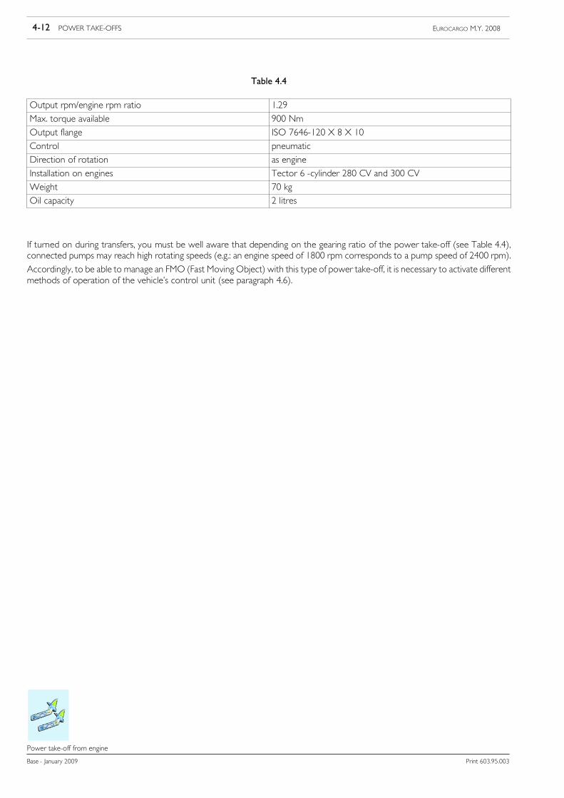
Table 4.4
Output rpm/engine rpm ratio 1.29
Max. torque available 900 Nm
Output flange ISO 7646-120 X 8 X 10
Control pneumatic
Direction of rotation as engine
Installation on engines Tector 6 -cylinder 280 CV and 300 CV
Weight 70 kg
Oil capacity 2 litres
If turned on during transfers, you must be well aware that depending on the gearing ratio of the power take-off (see Table 4.4),connected pumps may reach high rotating speeds (e.g.: an engine speed of 1800 rpm corresponds to a pump speed of 2400 rpm).
Accordingly, to be able to manage an FMO (Fast Moving Object) with this type of power take-off, it is necessary to activate differentmethods of operation of the vehicle’s control unit (see paragraph 4.6).
POWER TAKE-OFFS 4-13EUROCARGO M.Y. 2008
Print 603.95.003 Base - January 2009
PTO management
PTO management
4.6 PTO management
!Operations which do not comply with the instructions specified by IVECO or made by non qualifiedpersonnel can cause severe damage to on-board systems, effect driving safety and good operation ofthe vehicle and cause considerable damage which is not covered by warranty.
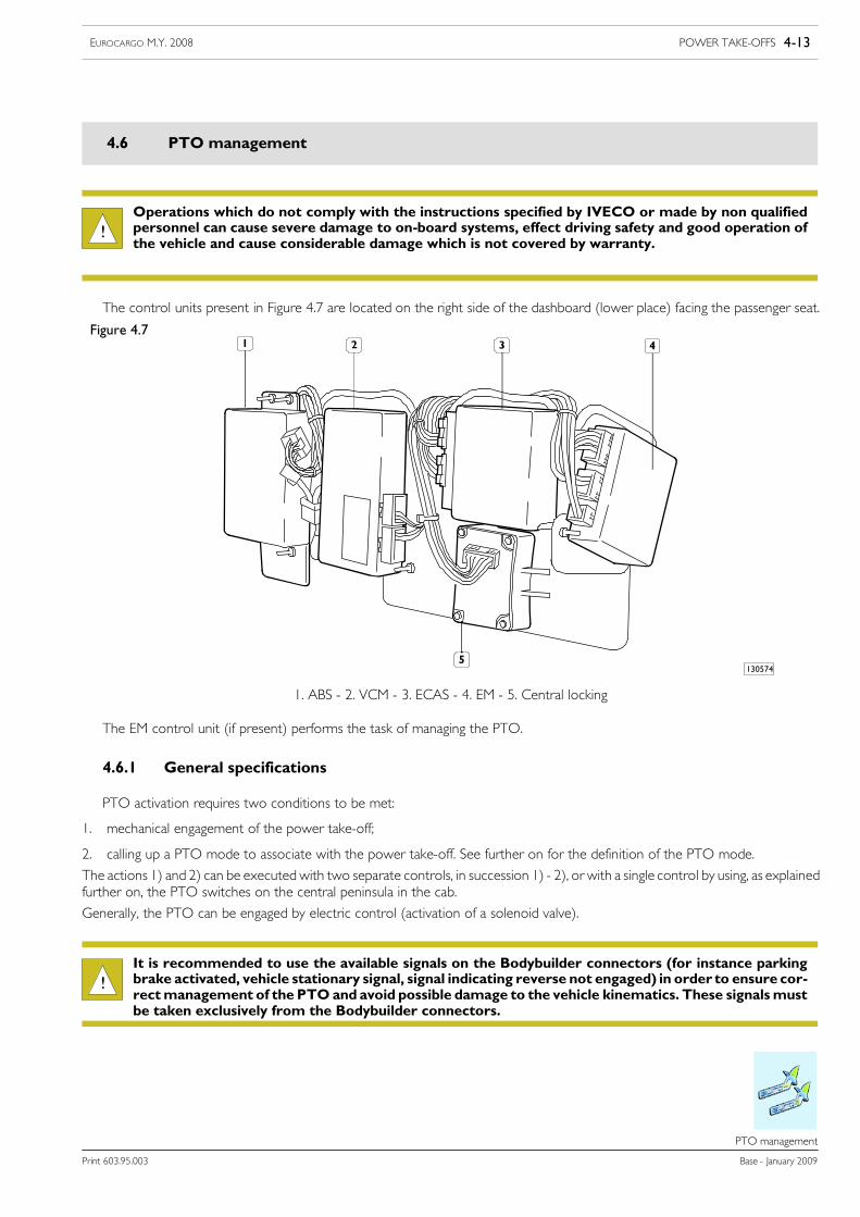
The control units present in Figure 4.7 are located on the right side of the dashboard (lower place) facing the passenger seat.
Figure 4.7
130574
1. ABS - 2. VCM - 3. ECAS - 4. EM - 5. Central locking
The EM control unit (if present) performs the task of managing the PTO.
4.6.1 General specifications
PTO activation requires two conditions to be met:
1. mechanical engagement of the power take-off;
2. calling up a PTO mode to associate with the power take-off. See further on for the definition of the PTO mode.
The actions 1) and 2) can be executed with two separate controls, in succession 1) - 2), or with a single control by using, as explainedfurther on, the PTO switches on the central peninsula in the cab.
Generally, the PTO can be engaged by electric control (activation of a solenoid valve).
!It is recommended to use the available signals on the Bodybuilder connectors (for instance parkingbrake activated, vehicle stationary signal, signal indicating reverse not engaged) in order to ensure cor-rectmanagement of the PTO and avoid possible damage to the vehicle kinematics. These signalsmustbe taken exclusively from the Bodybuilder connectors.
4-14 POWER TAKE-OFFS EUROCARGO M.Y. 2008
Base - January 2009 Print 603.95.003
PTO management
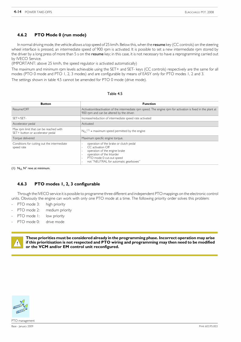
4.6.2 PTO Mode 0 (run mode)
In normal drivingmode, the vehicle allows a top speed of 25 km/h. Below this, when the resume key (CC controls) on the steeringwheel interface is pressed, an intermediate speed of 900 rpm is activated. It is possible to set a new intermediate rpm stored bythe driver by a long press of more than 5 s on the resume key; in this case, it is not necessary to have a reprogramming carried outby IVECO Service.(IMPORTANT: above 25 km/h, the speed regulator is activated automatically)
The maximum and minimum rpm levels achievable using the SET+ and SET- keys (CC controls) respectively are the same for allmodes (PTO 0 mode and PTO 1, 2, 3 modes) and are configurable by means of EASY only for PTO modes 1, 2 and 3.
The settings shown in table 4.5 cannot be amended for PTO 0 mode (drive mode).
Table 4.5
Button Function
Resume/OFF Activation/deactivation of the intermediate rpm speed. The engine rpm for activation is fixed in the plant at900 rpm and can be altered by the driver.
SET+/SET- Increase/reduction of intermediate speed rate activated
Accelerator pedal Activated
Max rpm limit that can be reached withSET+ button or accelerator pedal
NLL(1) ÷ maximum speed permitted by the engine
Torque delivered Maximum specific engine torque.
Conditions for cutting out the intermediatespeed rate
- operation of the brake or clutch pedal- CC activation Off- operation of the engine brake- operation of the Intarder- PTO mode 0 cut-out speed- not ”NEUTRAL for automatic gearboxes”
(1) NLL N° revs at minimum.
4.6.3 PTO modes 1, 2, 3 configurable
Through the IVECO service it is possible to programme three different and independent PTOmappings on the electronic controlunits. Obviously the engine can work with only one PTO mode at a time. The following priority order solves this problem:
- PTO mode 3: high priority
- PTO mode 2: medium priority
- PTO mode 1: low priority
- PTO mode 0: drive mode
!These prioritiesmust be considered already in the programming phase. Incorrect operationmay ariseif this prioritisation is not respected and PTO wiring and programming may then need to bemodifiedor the VCM and/or EM control unit reconfigured.

POWER TAKE-OFFS 4-15EUROCARGO M.Y. 2008
Print 603.95.003 Base - January 2009
PTO management
The following table shows the parameters that, as a whole, form a PTO mode. The parameters can only be programmed using aEASY diagnosis station, available at IVECO Service stations.
Table 4.6
Parameter Possible values
Maximum No. of revs that can be reached with SET+, NSET_max (9) NLL÷ Nmax (2)
Maximum rpm achievable by means of the accelerator pedal Nmax_acc
Engine revs increase with SET+ button 250 rpm for each second of pressing the button
Engine revs decrease with SET- button As above
Torque limitations (3) See Table
Runaway speed regulator gradient ”High Idle” vertical by default
Use of the CC buttons (Resume/OFF/SET+/SET-) Enabled / disabled
Storing of intermediate speed rate Fixed (EASY) / free (driver) (8)
’TIP function, for SET+/SET- buttons (4) Enabled / disabled
Exclusion of PTO mode using brake or clutch (for each mode separately) (5) Enabled / disabled
Accelerator pedal Enabled / disabled
Call-up intermediate speed rate stored with Resume on enabling PTO mode (7) Enabled / disabled
Minimum No. of revs that can be reached with SET-, NSET_min (9) > 500 rpm
Exclusion of PTO mode using parking brake (6) Enabled / disabled
Maximum speed of the vehicle, above which PTO mode is disabled (intermediate r.p.m. rate VZDR_max) between 2 km/h and 95 km/h (programmable)
Possible power take-off rate range (1) NLL÷ Maximum achievable rpm (2)
Abbreviations:NLL No. revs at minimumNmax Max. no. revsNres No. intermediate revs stored, is called up by pressing RESUME or enabling a PTO modeNSET_max Maximum No. of revs that can be reached with SET+ button, identical for all PTO modesNSET_min Minimum No. of revs that can be reached with SET- buttonNmax_acc Maximum rpm achievable by means of the accelerator pedal
(1) the speed to which we refer is that of the crankshaft and not that of the PTO. The corresponding number of revs of the power take-off must be calculatedby means of the power take-off reduction ratio.
(2) For setting the intermediate speed rate, the following rules apply:- you must never go below the value of NLL- you must never exceeded the value of Nmax- in general we will have NLL ≤ NSET_min ≤ Nres and Nres ≤ NSET_max ≤ Nmax. If this last inequality is not verified, the engine revs number is limited to the
value Nmax.
(3) See paragraph 4.6.3.1.
(4) The TIP function (quick pressure on the rocker key) allows you to gradually vary the intermediate rpm regulator or the speed regulator by a short press (<1s)on the SET+/SET-button.With the speed<25 Km/h the intermediate rpm regulator can be activated, with the speed>25 Km/h the speed regulator is activated.The change for the intermediate speed regulator is equal to 20rpmrpm for each TIP ie. 1 km/h for each TIPwith the speed regulator. Each TIP: 20 rpm(offset 5);default 20 rpm.
(5) On the power take-off mode is turned off with the activation of the service brake or clutch.Off the power take-off mode is not turned off with the activation of the service brake or clutch.In PTO mode 0, the power take-off mode is turned off with the activation of the service brake or clutch
(6) On the power take-off mode is turned off with the activation of the parking brake or clutch.Off the power take-off mode is not turned off with the activation of the parking brake or clutch.In PTO mode 0, the power take-off mode is not turned off with the activation of the parking brake.
(7) On the engine automatically goes up to the chosen Nres value for that power take-off mode.Off the engine remains at the previous rate, to reach the Nres value it is necessary to press the Resume button.
(8) See paragraph 4.6.7 Modifying the stored intermediate rpm Nres(9) Only settable values for PTO 1, 2, 3 modes.
4-16 POWER TAKE-OFFS EUROCARGO M.Y. 2008
Base - January 2009 Print 603.95.003
PTO management
4.6.3.1 Changes to the torque curve, final rotation speed and steepness of the final limiter
For mechanical power take-off protection, it is possible to limit:a) engine torque delivery as a protection against overload
b) engine rpm, as a protection against over-speed.
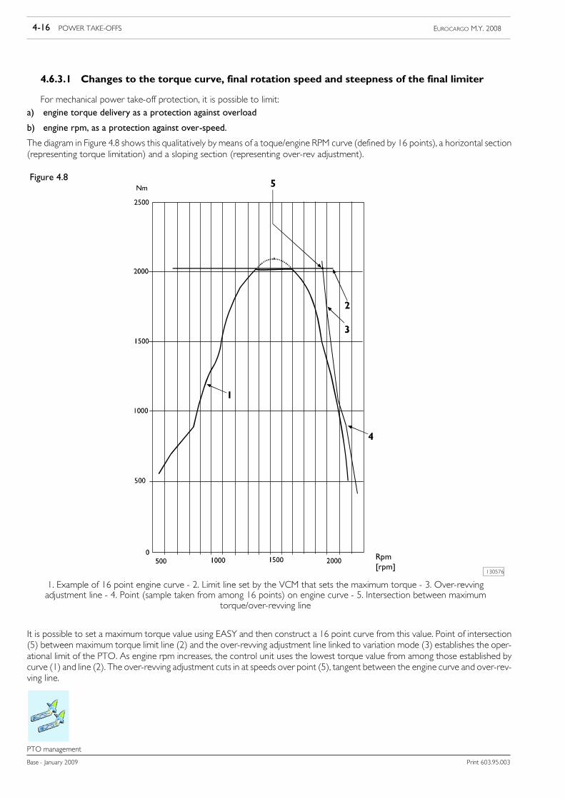
The diagram in Figure 4.8 shows this qualitatively by means of a toque/engine RPM curve (defined by 16 points), a horizontal section(representing torque limitation) and a sloping section (representing over-rev adjustment).
Figure 4.8
130576
1. Example of 16 point engine curve - 2. Limit line set by the VCM that sets the maximum torque - 3. Over-revvingadjustment line - 4. Point (sample taken from among 16 points) on engine curve - 5. Intersection between maximum
torque/over-revving line
Rpm[rpm]
It is possible to set a maximum torque value using EASY and then construct a 16 point curve from this value. Point of intersection(5) between maximum torque limit line (2) and the over-revving adjustment line linked to variation mode (3) establishes the oper-ational limit of the PTO. As engine rpm increases, the control unit uses the lowest torque value from among those established bycurve (1) and line (2). The over-revving adjustment cuts in at speeds over point (5), tangent between the engine curve and over-rev-ving line.
POWER TAKE-OFFS 4-17EUROCARGO M.Y. 2008
Print 603.95.003 Base - January 2009
PTO management
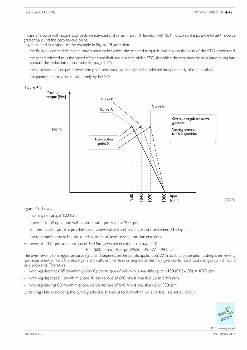
In case of a curve with accelerator pedal deactivated and a rise in rpm, TIP function with SET+ disabled, it is possible to set the curvegradient around the zero torque point.In general and in relation to the example in Figure 4.9, note that:
- the Bodybuilder establishes the maximum rpm for which the selected torque is available on the basis of the PTO mode used.
- the speed referred to is the speed of the crankshaft and not that of the PTO, for which the rpm must be calculated taking intoaccount the reduction ratio (Table 4.4 page 4-12).
- these limitations (torque, intersection point and curve gradient) may be selected independently of one another.
- the parameters may be activated only by IVECO.
Figure 4.9
126134
Maximumtorque [Nm]
600 Nm
Curve B
Curve CCurve A
Overrun regulator curvegradient:
Varying overrun0 ÷ 0.2 rpm/Nm
Intersectionpoint X
Rpm[rpm]
Figure 4.9 shows:
- max engine torque: 600 Nm.
- power take-off operation with intermediate rpm is set at 900 rpm.
- at intermediate rpm, it is possible to set a new value (rpm) but this must not exceed 1100 rpm.
- the rpm number must be calculated again for all over-revving rpm line gradients.
A power of 1100 rpm and a torque of 600 Nm give (see equations on page 4-3):P = (600 Nm x 1100 rpm)/9550= 69 kW = 94 bhp
The over-revving rpm regulator curve (gradient) depends on the specific application.With stationary operation, a steep over-revvingrpm adjustment curve is therefore generally sufficient, while in driving mode this may give rise to rapid load changes (which couldbe a problem). Therefore:- with regulator at 0.05 rpm/Nm (slope C) the torque of 600 Nm is available up to 1100-(0,05x600) = 1070 rpm.
- with regulator at 0.1 rpm/Nm (slope 8) the torque of 600 Nm is available up to 1040 rpm.
- wth regulator at 0.2 rpm/Nm (slope A) the torque of 600 Nm is available up to 980 rpm.
Under High Idle conditions, the curve gradient is still equal to 0 rpm/Nm, i.e. a vertical line set by default.
4-18 POWER TAKE-OFFS EUROCARGO M.Y. 2008
Base - January 2009 Print 603.95.003
PTO management
!The maximum rpm Nmax is a theoretical value. This is the engine rpm number at which the controlunit reduces the injected fuel quantity to 0mg/stroke. Since all engines according to their speed (enginewarm and with no load) need, in order to maintain this speed, a quantity of fuel of 20 to 30mg/stroke,this theoretical valueNmax is never reached.Depending on the angleof thecurve (gradient)of theover-rev regulator, the rpm actually reached is lower than 10 to 40 rpm. If this affects the application, weadvise defining the overrev speed with practical tests.
4.6.4 Intermediate speed rate governor
MaximumNo. of revs of the intermediate speed regulator that can be reached with the SET+, NSET_max button
The maximum number of revs obtainable with the SET+ button of the intermediate speed regulator (CC) can be configured.This limit is identical for all the PTO modes (drive mode 0, power take-off mode 1, 2 and 3).
TIP function
The TIP function, i.e. a very short press (< 1s) on the SET+/SET- button, allows a gradual change in the intermediate speedregulator or speed regulator.
With speed < V0 km/h (max speed of PTO mode) the intermediate speed regulator can be activated.With speed >V0 km/h the speed control is activated. The change for the intermediate speed rate regulator is equal to 20 rpm foreach TIP or 1 km/h for each TIP with the speed regulator.If the SET+ and SET- buttons are pressed any longer (>1s), the intermediate speed rate or the requested speed is modified continu-ously. The actual number of revs or true speed at the time of releasing the SET+ and SET - buttons is saved as the new requiredvalue.
The TIP function with SET+ and SET- can be turned off. This configuration is valid for all the PTOmodes (drive mode 0, PTOmode 1,2 and 3). Turning off the TIP function triggers the functional limitation on the speed regulator, therefore this change should onlybe used after a thorough examination.
This function is for regulating the hydraulic units.NOTE
Increase/decrease in the speed with SET+/SET-
With a longer press (>1s) on the SET+/SET- keys and with the TIP function deactivated (the TIP function is automatically deacti-vated by a long press on the SET+/SET- keys), the requested intermediate speed regulator value is altered and thus also the speed(engine rpm increase/decrease per second). The required time for this change can be calculated with the following formula:
Required time [s] = Difference in number of revs [rpm/s] / increase in revs per second [rpm/s/s]
Example: the intermediate number of revs must be taken from 800 rpm to 1800 rpm with the SET+ button. The difference in thenumber of revs is equal to 1000 rpm, therefore:
- with a speed of 250 rpm/s, the time interval is 1000/250 = 4s
Accelerator pedal on/off
In the normal drive mode (PTO mode 0) the accelerator pedal is always activated. In PTO modes 1, 2 or 3, the throttle pedalcan be turned off. In this case the PTO setting of the engine ignores the accelerator pedal. If however the accelerator pedal remainson, it is possible to increase the number of revs of the engine with this pedal up to the maximum number of revs Nmax valid at thatmoment.
POWER TAKE-OFFS 4-19EUROCARGO M.Y. 2008
Print 603.95.003 Base - January 2009
PTO management
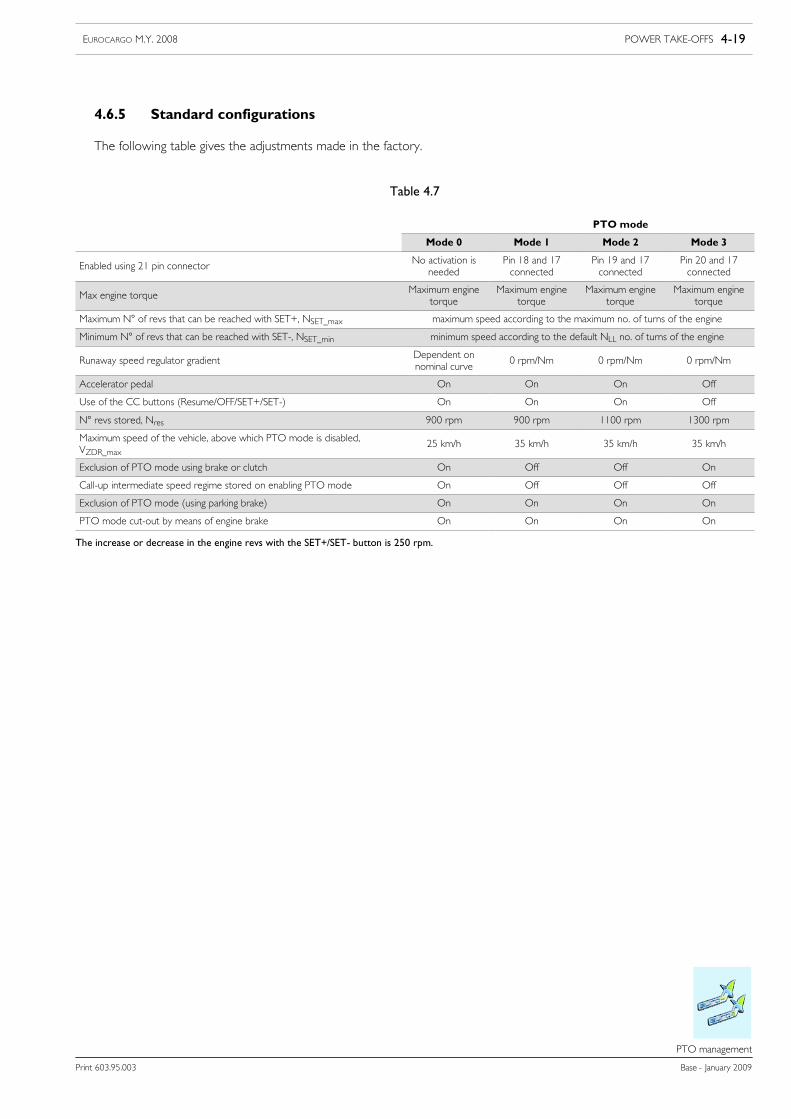
4.6.5 Standard configurations
The following table gives the adjustments made in the factory.
Table 4.7
PTO mode
Mode 0 Mode 1 Mode 2 Mode 3
Enabled using 21 pin connector No activation isneeded
Pin 18 and 17connected
Pin 19 and 17connected
Pin 20 and 17connected
Max engine torque Maximum enginetorque
Maximum enginetorque
Maximum enginetorque
Maximum enginetorque
Maximum N° of revs that can be reached with SET+, NSET_max maximum speed according to the maximum no. of turns of the engine
Minimum N° of revs that can be reached with SET-, NSET_min minimum speed according to the default NLL no. of turns of the engine
Runaway speed regulator gradient Dependent onnominal curve
0 rpm/Nm 0 rpm/Nm 0 rpm/Nm
Accelerator pedal On On On Off
Use of the CC buttons (Resume/OFF/SET+/SET-) On On On Off
N° revs stored, Nres 900 rpm 900 rpm 1100 rpm 1300 rpm
Maximum speed of the vehicle, above which PTO mode is disabled,VZDR_max
25 km/h 35 km/h 35 km/h 35 km/h
Exclusion of PTO mode using brake or clutch On Off Off On
Call-up intermediate speed regime stored on enabling PTO mode On Off Off Off
Exclusion of PTO mode (using parking brake) On On On On
PTO mode cut-out by means of engine brake On On On On
The increase or decrease in the engine revs with the SET+/SET- button is 250 rpm.
4-20 POWER TAKE-OFFS EUROCARGO M.Y. 2008
Base - January 2009 Print 603.95.003
PTO management
4.6.6 Specific indications: correlation between PTO configuration and power take-offs installed
No direct connection exists between the PTO mode (that can be activated by means of the 20-way coupling) and the powertake-offs physically installed on the vehicle. A Bodybuilder is therefore free to determine the necessary connections.This setting offers the possibility to use the power take-off(s) with different PTO configurations.If the work cycle requires the installed power take-off to operate under different conditions, for example, up to 3 PTO modes maybe used. Activation of the corresponding PTO modes must be commanded by EM or, if this is not present, by connection of therelevant connector (21-way above).Similarly, it is possible to configure a PTO mode without a physically-installed power take-off or with more than one physically-in-stalled power take-off.
4.6.7 Power take-off depending on the clutch
The power take-offs fitted on the gearbox can only be engaged with the clutch fully pressed.The PTO modes can be activated independently of this.
With Allison transmission
With an Allison transmission, engagement of the installed power take-off is coordinated by the transmission control unit andthe Expansion Module and occurs in the following stages:
- request to engage the power take-off (the gearbox control unit verifies the internal conditions to perform the operation safely:engine speed <900 rpm and gearbox output speed <250 rpm);
- activation of the solenoid valve by the control unit for engaging the power take-off;
- if the power take-off and hand brake are engaged at the same time, the gearbox automatically goes into neutral and PTOmode 2is activated (the relay located in the relay carrier plate of the transmission control unit on the rear cab wall is powered);
- verification of safe PTO operation (gearbox output speed <300 rpm).
The button for engaging the power take-off is located in the middle of the dashboard.
!Before activating the power take-off, the gearbox control unit checks several parameters (enginespeed <900 rpm and gearbox output speed 250 rpm). If all the conditions inside the gearbox are satis-fied, the Allison gearbox control unit will automatically engage the power take-off.The limitations (final speed,maximum torque etc.) of an active PTOmode still remain value even dur-ing engagement.Certain values can be modified by Allison Customer Service according to the requirements of theBodybuilder.
POWER TAKE-OFFS 4-21EUROCARGO M.Y. 2008
Print 603.95.003 Base - January 2009
PTO management
Use of the power take-off with vehicle in motion
If no limitations are necessary (e..g, on the torque, max. rpm, etc.) with a power take-off engaged, it is not necessary to activateany PTO mode.
In this case however the available power of the engine for driving is reduced (given the simultaneous draw for the body) and thiscan give rise to pick-up trouble. In some typical cases (e.g. tankers, waste collection vehicles etc.), this problem may be resolved byraising the idle rpm (low idle).
If however limitations are necessary (e..g, on the torque, max. rpm, etc.), it is necessary to activate a PTO mode.
!Especially with the vehicle in motion it is necessary bear in mind that, if a PTO mode is activated, thestored intermediate speed is activated at the same time and this can cause unwanted vehicle acceler-ation. The Bodybuilder must guarantee safe operation.
Engagement or disengagement of the power take-off depends on the power take-off used and the needs of the Bodybuilder.
For example: vehicle running (up to max. 30 km/h) with speed increased and power take-off engaged.
For several applications (use of the tipping box-body, cement mixer, waste collection, etc.) higher speeds are needed also whenmanoeuvring. This can be accomplished by:
- saving the intermediate speed rate Nres: fixed programming
- intermediate speed rate Nres: defined by the Bodybuilder
- turning off intermediate speed rate: turned off with clutch or brake
- accelerator pedal: on
- CC buttons: off
In this way the engine can work even with only the accelerator pedal set between the saved intermediate speed rate Nres and the max.speed, Nmax. If VZDR_max is reached, the intermediate speed regulator and therefore also the increase in the speed is turned off.
Changing the saved intermediate speed rate Nres
The intermediate speed rate can be modified separately for each PTO mode.We need to distinguish between two possibilities:
1) fixed programming (EASY)For power take-off mode 0 (runningmode) this possibility is not available; a change is only possible by reprogramming with EASYat an IVECO Service station
2) free programming (by the driver)To change the intermediate speed rate you need to:
- activate a PTO mode whose intermediate speed rate has to be modified
- set the desired speed using SET+/SET
- press CC Resume for more than 5 sec.
Using the E.A.SY. station must be preceded b updating the EASY software.NOTE
4-22 POWER TAKE-OFFS EUROCARGO M.Y. 2008
Base - January 2009 Print 603.95.003
PTO management
Adjustment of minimum rpm
Adjusting the speed rate at idle speed can only be done with the engine warm. The adjustment is made in three stages:
1) Activation of the idle speed setting
With engine idling:
- operate the service brake (and maintain operated to the end of regulation)
- press the Resume button for more than 3 sec (and then release)Immediately after this, the idle rpm will drop to a minimum value.
2) Changing the speed rate at idle speedThe CC SET+ or CC SET-, the idling rpm number may be adjusted through 20 rpm.
3) Saving the speed rate at idle speedSaving is done by pressing CC Resume again (for more than 3 sec.)
!The speed rate at idle speed can only be adjusted in the PTOmodes with which the CC buttons wereactivated or the intermediate speed rate adjustment was turned off with the brake or with the clutch.
In PTO modes, the no-load speed rpm adjustment range is 100 rpm from the factory value. This interval may be increased to200 rpm by reprogramming at an IVECO service outlet. The adjustment interval for the speed rate with no load is identical forall the power take-off modes (running mode 0 power take-off modes 1, 2 and 3).
Influence of the retarder on the intermediate speed rate regulator
Operating the retarder turns off the intermediate speed regulator (identical effect to the CC commandOff). All the CC buttons(CC Resume / SET+ / SET-) are ignored with the retarder operated.
!If there is the configuration: Cutting off the intermediate speed rate with brake or clutch = off, and theintermediate speed rate is below 900 min-1, on operating the retarder, the intermediate speed rateregulator is not cut off.When the retarder is operated, the engine rpm drops to the no-load speed andall the CC keys (CC Resume/SET+/SET-) are ignored. After cancelling the operation, the original rpmwill be restored.

POWER TAKE-OFFS 4-23EUROCARGO M.Y. 2008
Print 603.95.003 Base - January 2009
PTO management
Influence of the engine brake on the intermediate speed rate regulator
The engine brake can be activated in the following ways:
1. pressing the engine brake button (cab floor);2. pre-engaging the brake (with the brake applied the engine brake is automatically activated).
The selection is made with a switch on the instrument panel.If the engine brake is activated by means of option 2, the intermediate rpm number regulator is automatically deactivated.All the CC buttons (CC OFF / Resume / SET+ / SET-) are ignored during active operation of the engine brake with the pedal.
Simultaneous operation of SET+ and SET-
These functions are mutually exclusive. In the case of simultaneous activation, for safety reasons, CCOff is activated after 500 msat most. If the keys are pressed simultaneously, the VCM would recognise an error after 500 ms.
4.6.8 Second speed limiter
This function can be enabled independently from the various power PTO modes (run mode 0, power take-off modes 1, 2, 3)The value can be programmed by IVECO Service using an EASY station. The second speed limiter is enabled by a closed contactbetween pins 1 and 2 of the 5 pin connector.
Using the E.A.SY. station must be preceded b updating the EASY software.NOTE
4-24 POWER TAKE-OFFS EUROCARGO M.Y. 2008
Base - January 2009 Print 603.95.003
Electrical system
Electrical system
4.7 Electrical system
See paragraph 5.7.
4.8 Pneumatic system
To supply the PTO control solenoid, take air from service circuit (fig. 5.7, chapter 5) and add an 8.5 bar pressure limit valve.
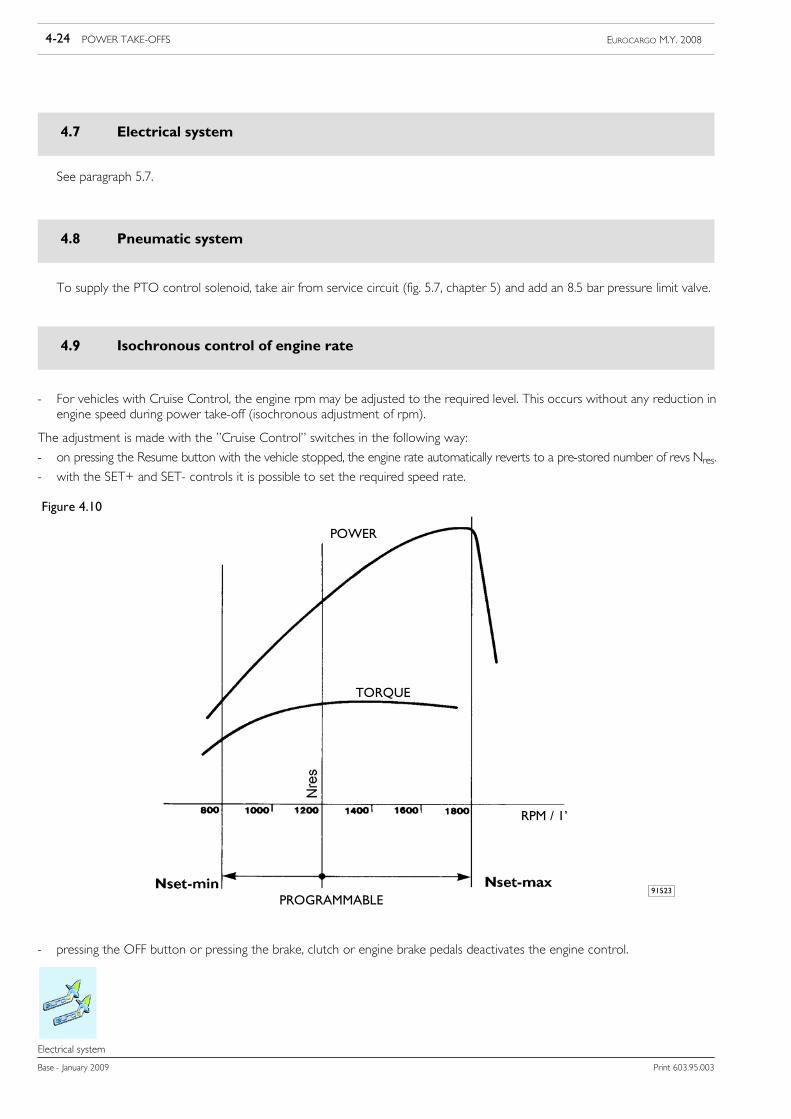
4.9 Isochronous control of engine rate
- For vehicles with Cruise Control, the engine rpm may be adjusted to the required level. This occurs without any reduction inengine speed during power take-off (isochronous adjustment of rpm).
The adjustment is made with the ”Cruise Control” switches in the following way:
- on pressing the Resume button with the vehicle stopped, the engine rate automatically reverts to a pre-stored number of revs Nres.
- with the SET+ and SET- controls it is possible to set the required speed rate.
Figure 4.10
91523
TORQUE
RPM / 1’
POWER
PROGRAMMABLE
- pressing the OFF button or pressing the brake, clutch or engine brake pedals deactivates the engine control.
POWER TAKE-OFFS 4-25EUROCARGO M.Y. 2008
Print 603.95.003 Base - January 2009
Isochronous control of engine rate
Isochronous control of engine rate
For power take-offs when you want to set different values for Nres and NSET_max and NSET_min than the ones set (e.g., to avoidoverrevving at the pumps), the system enables saving the new values in the control unit.
This operation is performed by theCentres of the IVECONetwork equippedwith EASY stations, providing the following indications:• type of vehicle; no. of chassis frame• type of engine; serial number• desired Nres (rpm)• desired NSET_max (rpm)• desired NSET_min (rpm).
The system allows adjustment of Nres up to NSET_max - 50 (rpm).
Using the E.A.SY. station must be preceded b updating the EASY software.NOTE

4-26 POWER TAKE-OFFS EUROCARGO M.Y. 2008
Base - January 2009 Print 603.95.003
Isochronous control of engine rate
SPECIAL INSTRUCTIONS FOR ELECTRONIC SUBSYSTEMS 5-1EUROCARGO M.Y. 2008
Print 603.95.003 Base - January 2009
Index
Index
SECTION 5
Special instructions for electronic subsystems
Page
5.1 Electronic system 5-3
5.2 Bodybuilder connectors 5-4
5.2.1 Positioning inside the cab 5-4
5.2.2 On the chassis frame 5-9
5.3 Installation of anti-theft devices 5-12
5.4 Fitting for tail lift -opt 4113 5-13
5.5 Fitting for tail lift + 2nd ECAS remote control - opt 4115 5-14
5.6 FMS 5-14
5.7 EM (Expansion Module) 5-15
5.7.1 Connections 5-16
5.7.2 PTO on/off conditions 5-17
5.7.3 No PTO or PTO setups installed: 5-17
5.7.4 PTO Multipower 5-17
5.7.5 Manual transmission PTO with electrical engagement 5-18
5.7.6 Allison transmission PTO 5-18
5.8 Electrical system: modifications and drawing-off power 5-19
5.8.1 General Information 5-19
5.8.2 Electromagnetic Compatibility 5-20
5.8.3 Additional equipment 5-26
5.8.4 Electrical power draw-off 5-29
5.8.5 Main switch of the batteries (optional) 5-32
5.8.6 Additional circuits 5-33
5.8.7 Operations for changing the wheelbase and the overhang 5-34
5.8.8 Drawing power at a different voltage to that of the system 5-34
5.8.9 Arrangement of Side Marker Lamps 5-35

5-2 SPECIAL INSTRUCTIONS FOR ELECTRONIC SUBSYSTEMS EUROCARGO M.Y. 2008
Base - January 2009 Print 603.95.003
Index
SPECIAL INSTRUCTIONS FOR ELECTRONIC SUBSYSTEMS 5-3EUROCARGO M.Y. 2008
Print 603.95.003 Base - January 2009
Electronic system
55555.
Electronic system
5.1 Electronic system
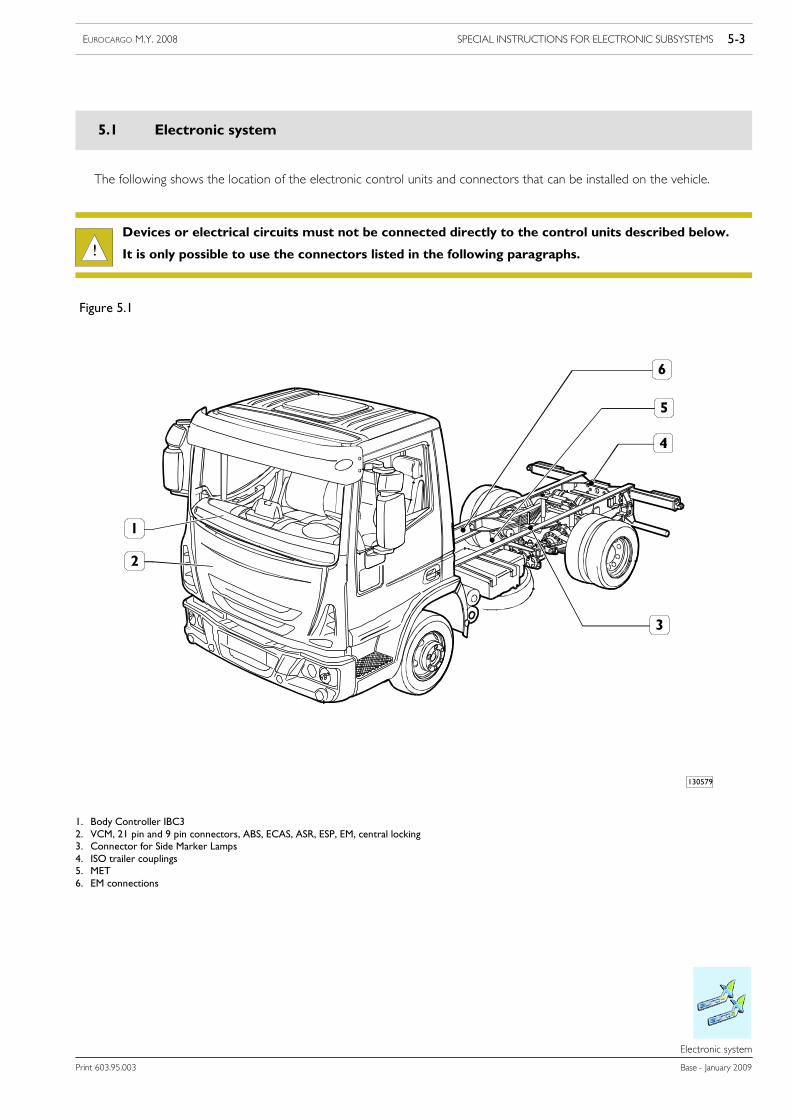
The following shows the location of the electronic control units and connectors that can be installed on the vehicle.
!Devices or electrical circuits must not be connected directly to the control units described below.
It is only possible to use the connectors listed in the following paragraphs.
130579
Figure 5.1
1. Body Controller IBC32. VCM, 21 pin and 9 pin connectors, ABS, ECAS, ASR, ESP, EM, central locking3. Connector for Side Marker Lamps4. ISO trailer couplings5. MET6. EM connections
5-4 SPECIAL INSTRUCTIONS FOR ELECTRONIC SUBSYSTEMS EUROCARGO M.Y. 2008
Base - January 2009 Print 603.95.003
Bodybuilder connectors
Bodybuilder connectors
5.2 Bodybuilder connectors
In the following paragraphs, the Bodybuilders’ connectors are reported according to their position on the vehicle. To use thesebodybuilders’ connectors, order set 2994016 from Parts, made up of connectors, terminal and protective rubber caps.
5.2.1 Positioning inside the cab
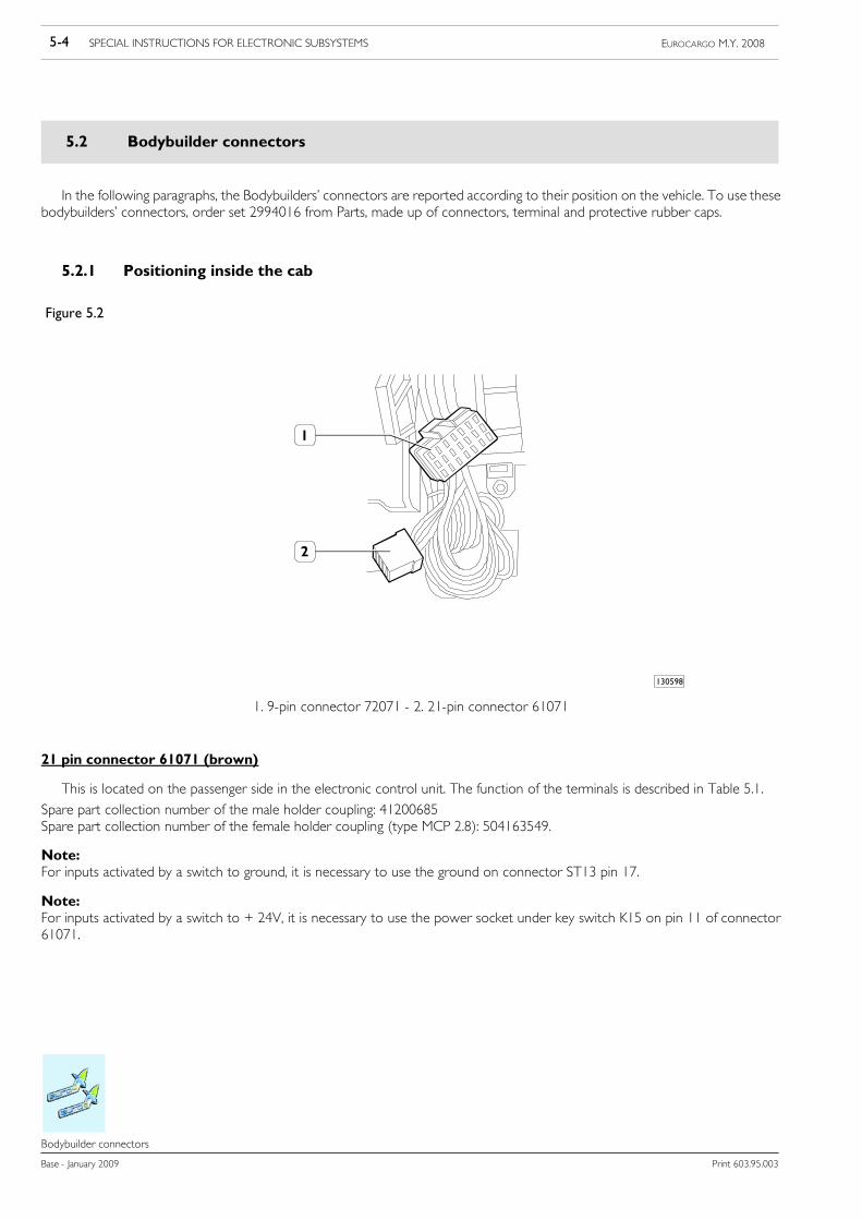
Figure 5.2
130598
1. 9-pin connector 72071 - 2. 21-pin connector 61071
21 pin connector 61071 (brown)
This is located on the passenger side in the electronic control unit. The function of the terminals is described in Table 5.1.
Spare part collection number of the male holder coupling: 41200685Spare part collection number of the female holder coupling (type MCP 2.8): 504163549.
Note:For inputs activated by a switch to ground, it is necessary to use the ground on connector ST13 pin 17.
Note:For inputs activated by a switch to + 24V, it is necessary to use the power socket under key switch K15 on pin 11 of connector61071.
SPECIAL INSTRUCTIONS FOR ELECTRONIC SUBSYSTEMS 5-5EUROCARGO M.Y. 2008
Print 603.95.003 Base - January 2009
Bodybuilder connectors
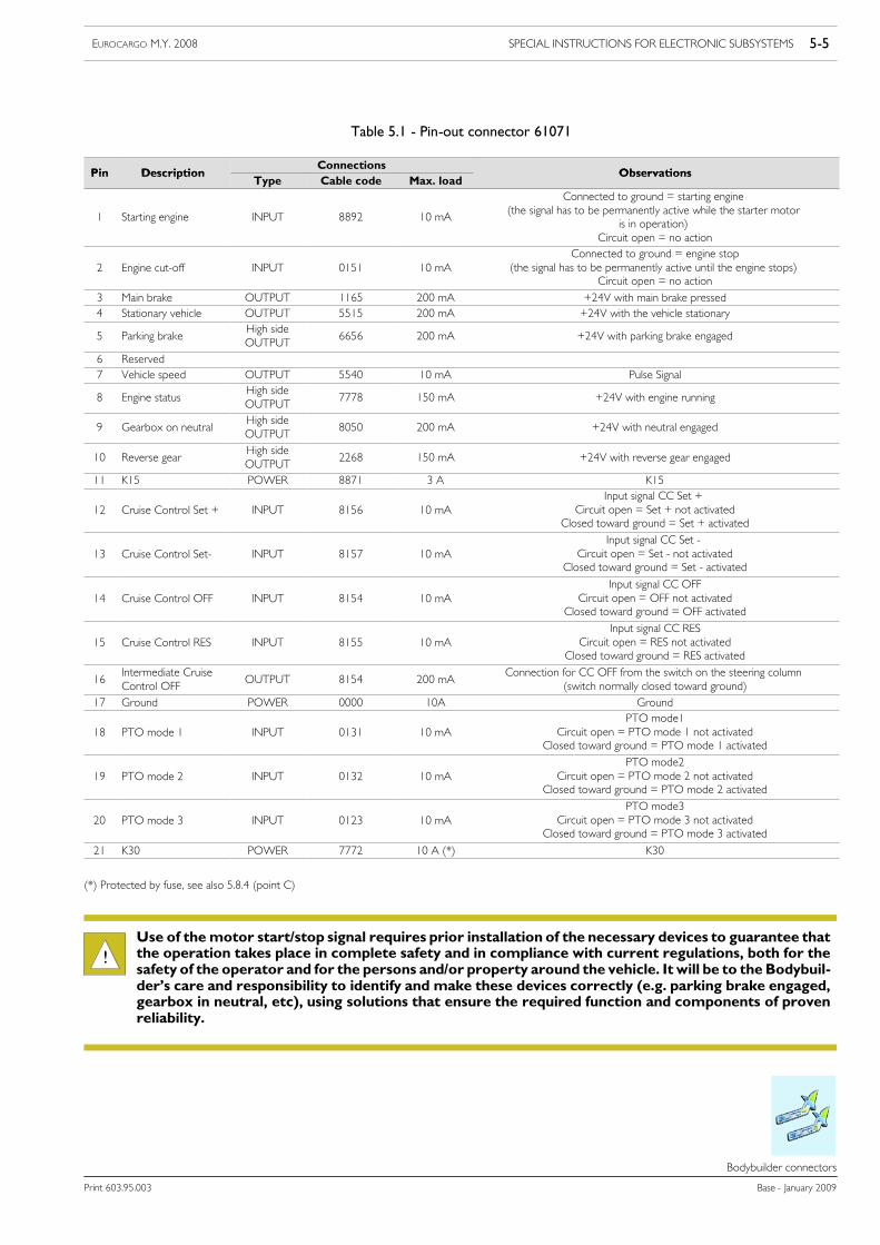
Table 5.1 - Pin-out connector 61071
Pin DescriptionConnections
ObservationsPin DescriptionType Cable code Max. load
Observations
1 Starting engine INPUT 8892 10 mA
Connected to ground = starting engine(the signal has to be permanently active while the starter motor
is in operation)Circuit open = no action
2 Engine cut-off INPUT 0151 10 mAConnected to ground = engine stop
(the signal has to be permanently active until the engine stops)Circuit open = no action
3 Main brake OUTPUT 1165 200 mA +24V with main brake pressed4 Stationary vehicle OUTPUT 5515 200 mA +24V with the vehicle stationary
5 Parking brakeHigh sideOUTPUT
6656 200 mA +24V with parking brake engaged
6 Reserved7 Vehicle speed OUTPUT 5540 10 mA Pulse Signal
8 Engine statusHigh sideOUTPUT
7778 150 mA +24V with engine running
9 Gearbox on neutralHigh sideOUTPUT
8050 200 mA +24V with neutral engaged
10 Reverse gearHigh sideOUTPUT
2268 150 mA +24V with reverse gear engaged
11 K15 POWER 8871 3 A K15
12 Cruise Control Set + INPUT 8156 10 mAInput signal CC Set +
Circuit open = Set + not activatedClosed toward ground = Set + activated
13 Cruise Control Set- INPUT 8157 10 mAInput signal CC Set -
Circuit open = Set - not activatedClosed toward ground = Set - activated
14 Cruise Control OFF INPUT 8154 10 mAInput signal CC OFF
Circuit open = OFF not activatedClosed toward ground = OFF activated
15 Cruise Control RES INPUT 8155 10 mAInput signal CC RES
Circuit open = RES not activatedClosed toward ground = RES activated
16Intermediate CruiseControl OFF
OUTPUT 8154 200 mAConnection for CC OFF from the switch on the steering column
(switch normally closed toward ground)17 Ground POWER 0000 10A Ground
18 PTO mode 1 INPUT 0131 10 mAPTO mode1
Circuit open = PTO mode 1 not activatedClosed toward ground = PTO mode 1 activated
19 PTO mode 2 INPUT 0132 10 mAPTO mode2
Circuit open = PTO mode 2 not activatedClosed toward ground = PTO mode 2 activated
20 PTO mode 3 INPUT 0123 10 mAPTO mode3
Circuit open = PTO mode 3 not activatedClosed toward ground = PTO mode 3 activated
21 K30 POWER 7772 10 A (*) K30
(*) Protected by fuse, see also 5.8.4 (point C)
!Use of themotor start/stop signal requires prior installation of the necessary devices to guarantee thatthe operation takes place in complete safety and in compliance with current regulations, both for thesafety of the operator and for the persons and/or property around the vehicle. It will be to the Bodybuil-der’s care and responsibility to identify and make these devices correctly (e.g. parking brake engaged,gearbox in neutral, etc), using solutions that ensure the required function and components of provenreliability.
5-6 SPECIAL INSTRUCTIONS FOR ELECTRONIC SUBSYSTEMS EUROCARGO M.Y. 2008
Base - January 2009 Print 603.95.003
Bodybuilder connectors
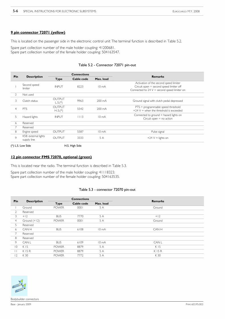
9 pin connector 72071 (yellow)
This is located on the passenger side in the electronic control unit The terminal function is described in Table 5.2.
Spare part collection number of the male holder coupling: 41200681.Spare part collection number of the female holder coupling: 504163547.
Table 5.2 - Connector 72071 pin-out
Pin DescriptionConnections
RemarksPin DescriptionType Cable code Max. load
Remarks
1Second speedlimiter
INPUT 8223 10 mAActivation of the second speed limiterCircuit open = second speed limiter off
Connected to 24 V = second speed limiter on
2 Not used
3 Clutch statusOUTPUTL..S.(*)
9963 200 mA Ground signal with clutch pedal depressed
4 PTSOUTPUTH..S.(*)
5542 200 mAPTS = programmable speed threshold+24 V = when the threshold is exceeded
5 Hazard lights INPUT 1113 10 mAConnected to ground = hazard lights on
Circuit open = no action
6 Reserved
7 Reserved
8 Engine speed OUTPUT 5587 10 mA Pulse signal
9K58: external lightssupply line
OUTPUT 3333 5 A +24 V = lights on
(*) L.S. Low Side H.S. High Side
12 pin connector FMS 72070, optional (green)
This is located near the radio. The terminal function is described in Table 5.3.
Spare part collection number of the male holder coupling: 41118323.Spare part collection number of the female holder coupling: 504163535.
Table 5.3 - connector 72070 pin-out
Pin DescriptionConnections
RemarksPin DescriptionType Cable code Max. load
Remarks
1 Ground POWER 0001 5 A Ground
2 Reserved
3 +12 BUS 7770 5 A +12
4 Ground (+12) POWER 0001 5 A Ground
5 Reserved
6 CAN H BUS 6108 10 mA CAN H
7 Reserved
8 Reserved
9 CAN L BUS 6109 10 mA CAN L
10 K 15 POWER 8879 5 A K 15
11 K 15 R POWER 8879 5 A K 15 R
12 K 30 POWER 7772 5 A K 30
SPECIAL INSTRUCTIONS FOR ELECTRONIC SUBSYSTEMS 5-7EUROCARGO M.Y. 2008
Print 603.95.003 Base - January 2009
Bodybuilder connectors
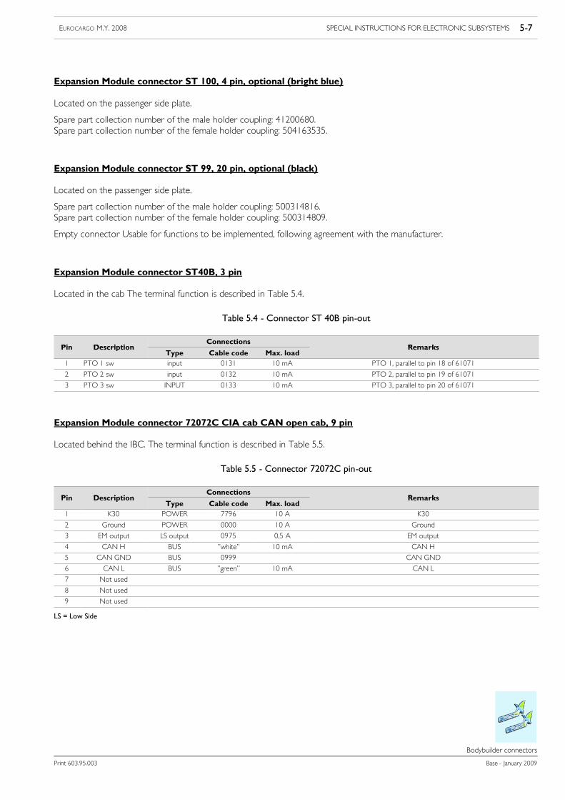
Expansion Module connector ST 100, 4 pin, optional (bright blue)
Located on the passenger side plate.
Spare part collection number of the male holder coupling: 41200680.Spare part collection number of the female holder coupling: 504163535.
Expansion Module connector ST 99, 20 pin, optional (black)
Located on the passenger side plate.
Spare part collection number of the male holder coupling: 500314816.Spare part collection number of the female holder coupling: 500314809.
Empty connector Usable for functions to be implemented, following agreement with the manufacturer.
Expansion Module connector ST40B, 3 pin
Located in the cab The terminal function is described in Table 5.4.
Table 5.4 - Connector ST 40B pin-out
Pin DescriptionConnections
RemarksPin DescriptionType Cable code Max. load
Remarks
1 PTO 1 sw input 0131 10 mA PTO 1, parallel to pin 18 of 61071
2 PTO 2 sw input 0132 10 mA PTO 2, parallel to pin 19 of 61071
3 PTO 3 sw INPUT 0133 10 mA PTO 3, parallel to pin 20 of 61071
Expansion Module connector 72072C CIA cab CAN open cab, 9 pin
Located behind the IBC. The terminal function is described in Table 5.5.
Table 5.5 - Connector 72072C pin-out
Pin DescriptionConnections
RemarksPin DescriptionType Cable code Max. load
Remarks
1 K30 POWER 7796 10 A K30
2 Ground POWER 0000 10 A Ground
3 EM output LS output 0975 0,5 A EM output
4 CAN H BUS ”white” 10 mA CAN H
5 CAN GND BUS 0999 CAN GND
6 CAN L BUS ”green” 10 mA CAN L
7 Not used
8 Not used
9 Not used
LS = Low Side
5-8 SPECIAL INSTRUCTIONS FOR ELECTRONIC SUBSYSTEMS EUROCARGO M.Y. 2008
Base - January 2009 Print 603.95.003
Bodybuilder connectors
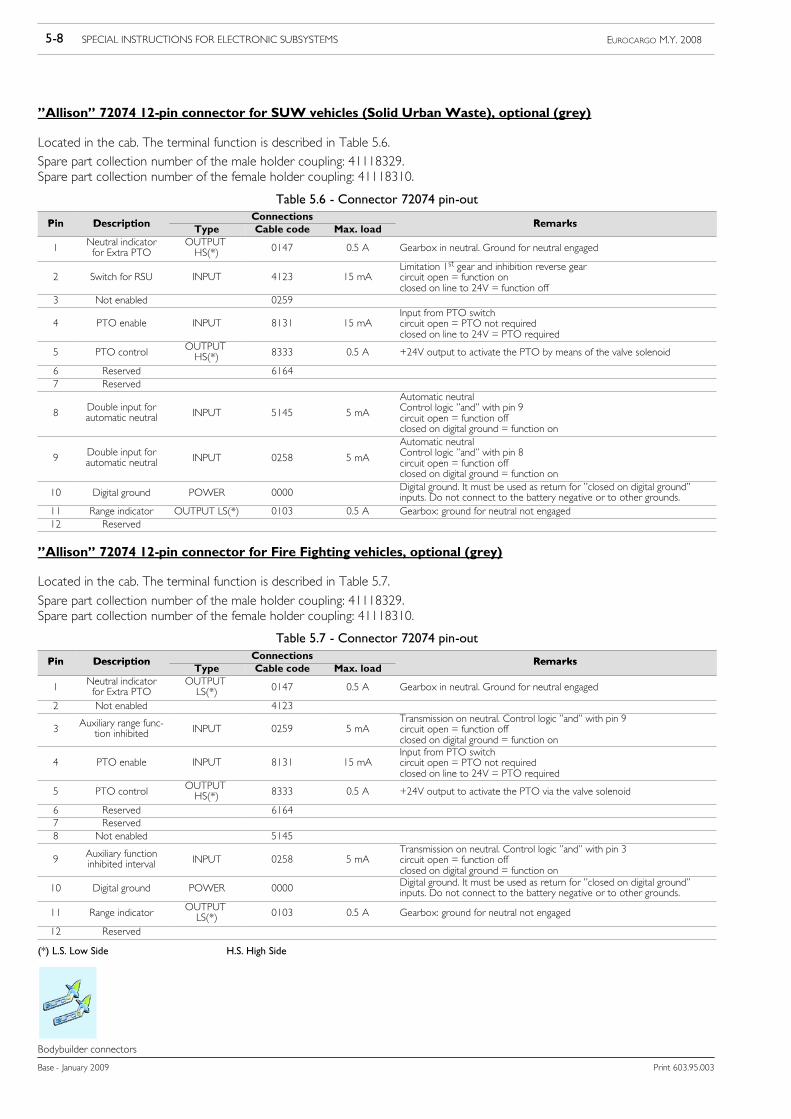
”Allison” 72074 12-pin connector for SUW vehicles (Solid Urban Waste), optional (grey)
Located in the cab. The terminal function is described in Table 5.6.Spare part collection number of the male holder coupling: 41118329.Spare part collection number of the female holder coupling: 41118310.
Table 5.6 - Connector 72074 pin-out
Pin DescriptionConnections
RemarksPin Description Type Cable code Max. load Remarks
1 Neutral indicatorfor Extra PTO
OUTPUTHS(*) 0147 0.5 A Gearbox in neutral. Ground for neutral engaged
2 Switch for RSU INPUT 4123 15 mALimitation 1st gear and inhibition reverse gearcircuit open = function onclosed on line to 24V = function off
3 Not enabled 0259
4 PTO enable INPUT 8131 15 mAInput from PTO switchcircuit open = PTO not requiredclosed on line to 24V = PTO required
5 PTO control OUTPUTHS(*) 8333 0.5 A +24V output to activate the PTO by means of the valve solenoid
6 Reserved 61647 Reserved
8 Double input forautomatic neutral INPUT 5145 5 mA
Automatic neutralControl logic ”and” with pin 9circuit open = function offclosed on digital ground = function on
9 Double input forautomatic neutral INPUT 0258 5 mA
Automatic neutralControl logic ”and” with pin 8circuit open = function offclosed on digital ground = function on
10 Digital ground POWER 0000 Digital ground. It must be used as return for ”closed on digital ground”inputs. Do not connect to the battery negative or to other grounds.
11 Range indicator OUTPUT LS(*) 0103 0.5 A Gearbox: ground for neutral not engaged12 Reserved
”Allison” 72074 12-pin connector for Fire Fighting vehicles, optional (grey)
Located in the cab. The terminal function is described in Table 5.7.
Spare part collection number of the male holder coupling: 41118329.Spare part collection number of the female holder coupling: 41118310.
Table 5.7 - Connector 72074 pin-out
Pin Description Connections RemarksPin DescriptionType Cable code Max. load
Remarks
1 Neutral indicatorfor Extra PTO
OUTPUTLS(*) 0147 0.5 A Gearbox in neutral. Ground for neutral engaged
2 Not enabled 4123
3 Auxiliary range func-tion inhibited INPUT 0259 5 mA
Transmission on neutral. Control logic ”and” with pin 9circuit open = function offclosed on digital ground = function on
4 PTO enable INPUT 8131 15 mAInput from PTO switchcircuit open = PTO not requiredclosed on line to 24V = PTO required
5 PTO control OUTPUTHS(*) 8333 0.5 A +24V output to activate the PTO via the valve solenoid
6 Reserved 61647 Reserved8 Not enabled 5145
9 Auxiliary functioninhibited interval INPUT 0258 5 mA
Transmission on neutral. Control logic ”and” with pin 3circuit open = function offclosed on digital ground = function on
10 Digital ground POWER 0000 Digital ground. It must be used as return for ”closed on digital ground”inputs. Do not connect to the battery negative or to other grounds.
11 Range indicator OUTPUTLS(*) 0103 0.5 A Gearbox: ground for neutral not engaged
12 Reserved
(*) L.S. Low Side H.S. High Side
SPECIAL INSTRUCTIONS FOR ELECTRONIC SUBSYSTEMS 5-9EUROCARGO M.Y. 2008
Print 603.95.003 Base - January 2009
Bodybuilder connectors
5.2.2 Positioning on the chassis
Expansion Module connector 72072D CIA frame CAN open frame, 7 pin
It is located on the left side of the frame. The terminal function is described in Table 5.8.
Table 5.8 - Connector 72072D pin out
Pin DescriptionConnections
RemarksPin DescriptionType Cable code Max. load
Remarks
1 +K30 POWER 7796 10 A K30
2 Ground POWER 0000 10 A Ground
3 EM output LS output 0975 0,5 A EM output
4 CAN H BUS ”white” 10 mA CAN H
5 CAN GND BUS 0999 CAN GND
6 CAN L BUS ”green” 10 mA CAN L7 Not used - - - -
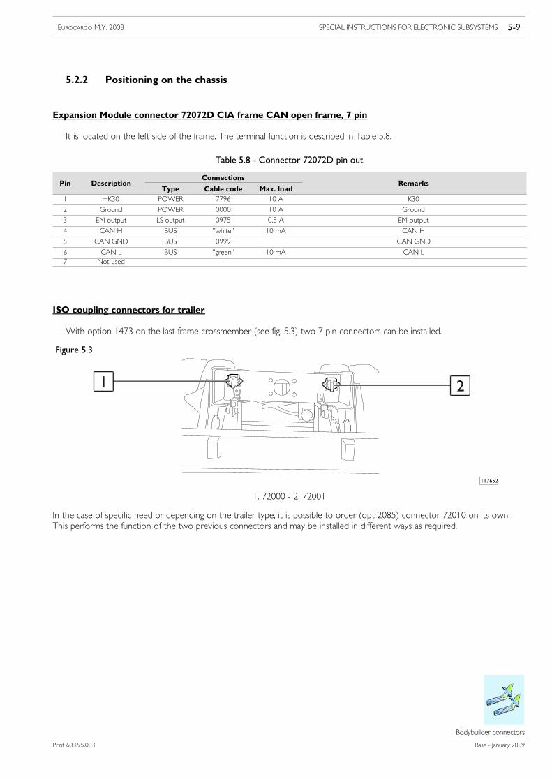
ISO coupling connectors for trailer
With option 1473 on the last frame crossmember (see fig. 5.3) two 7 pin connectors can be installed.
Figure 5.3
117652
1 2
1. 72000 - 2. 72001
In the case of specific need or depending on the trailer type, it is possible to order (opt 2085) connector 72010 on its own.This performs the function of the two previous connectors and may be installed in different ways as required.

5-10 SPECIAL INSTRUCTIONS FOR ELECTRONIC SUBSYSTEMS EUROCARGO M.Y. 2008
Base - January 2009 Print 603.95.003
Bodybuilder connectors
Table 5.9 - 7-pin connector 72000 pin-out
Pin no. wire max load Description
1 0000 Ground
2 3331 Rear RH clearance and parking light
3 1180 - Trailer rear LH direction indicator
4 1117 Control unit connection in cab
5 1185 Trailer rear RH direction indicator
6 3332 Max 10A Rear LH clearance and parking light
7 8890 - Solenoid valve supply for trailer brake
Table 5.10 - 7-pin connector 72001 pin-out
Pin no. wire max load Description
1 0 Ground
2 Free -
3 2226 - Reversing lights
4 8890 5 A Key positive (15), connected directly with fuse no. 56 of the interconnection control unit
5 Free -
6 Free -
7 2283 - Rear fog lights
or
Table 5.11 - Connector 72010 pin-out (15-pin)
Pin no. wire max load Description
1 1180 Trailer rear LH direction indicators
2 1185 Trailer rear RH direction indicators
3 2286
4 0000 Ground
5 3332 Rear LH clearance and parking lights
6 3331 Rear RH clearance and parking lights
7 1179 Trailer brake lights
8 2226 Reversing lights
9 Free
10 Free
11 Free
12 Free
13 Free
14 Free
15 Free
SPECIAL INSTRUCTIONS FOR ELECTRONIC SUBSYSTEMS 5-11EUROCARGO M.Y. 2008
Print 603.95.003 Base - January 2009
Bodybuilder connectors
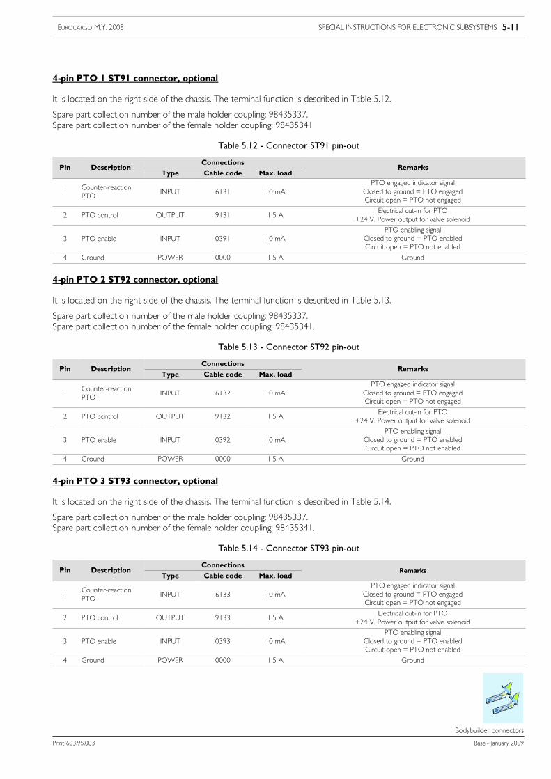
4-pin PTO 1 ST91 connector, optional
It is located on the right side of the chassis. The terminal function is described in Table 5.12.
Spare part collection number of the male holder coupling: 98435337.Spare part collection number of the female holder coupling: 98435341
Table 5.12 - Connector ST91 pin-out
Pin DescriptionConnections
RemarksPin DescriptionType Cable code Max. load
Remarks
1Counter-reactionPTO
INPUT 6131 10 mAPTO engaged indicator signal
Closed to ground = PTO engagedCircuit open = PTO not engaged
2 PTO control OUTPUT 9131 1.5 AElectrical cut-in for PTO
+24 V. Power output for valve solenoid
3 PTO enable INPUT 0391 10 mAPTO enabling signal
Closed to ground = PTO enabledCircuit open = PTO not enabled
4 Ground POWER 0000 1.5 A Ground
4-pin PTO 2 ST92 connector, optional
It is located on the right side of the chassis. The terminal function is described in Table 5.13.
Spare part collection number of the male holder coupling: 98435337.Spare part collection number of the female holder coupling: 98435341.
Table 5.13 - Connector ST92 pin-out
Pin DescriptionConnections
RemarksPin DescriptionType Cable code Max. load
Remarks
1Counter-reactionPTO
INPUT 6132 10 mAPTO engaged indicator signal
Closed to ground = PTO engagedCircuit open = PTO not engaged
2 PTO control OUTPUT 9132 1.5 AElectrical cut-in for PTO
+24 V. Power output for valve solenoid
3 PTO enable INPUT 0392 10 mAPTO enabling signal
Closed to ground = PTO enabledCircuit open = PTO not enabled
4 Ground POWER 0000 1.5 A Ground
4-pin PTO 3 ST93 connector, optional
It is located on the right side of the chassis. The terminal function is described in Table 5.14.
Spare part collection number of the male holder coupling: 98435337.Spare part collection number of the female holder coupling: 98435341.
Table 5.14 - Connector ST93 pin-out
Pin DescriptionConnections
RemarksPin DescriptionType Cable code Max. load
Remarks
1Counter-reactionPTO
INPUT 6133 10 mAPTO engaged indicator signal
Closed to ground = PTO engagedCircuit open = PTO not engaged
2 PTO control OUTPUT 9133 1.5 AElectrical cut-in for PTO
+24 V. Power output for valve solenoid
3 PTO enable INPUT 0393 10 mAPTO enabling signal
Closed to ground = PTO enabledCircuit open = PTO not enabled
4 Ground POWER 0000 1.5 A Ground
5-12 SPECIAL INSTRUCTIONS FOR ELECTRONIC SUBSYSTEMS EUROCARGO M.Y. 2008
Base - January 2009 Print 603.95.003
Installation of anti-theft devices
Installation of anti---theft devices
5.3 Installation of anti-theft devices
For their installation, observe the precautions and indications given below.
Types of anti-theft systems:
IVECO recommends using products that meet the requirements and are approved by the recognized institutes such as ANIA,TÜV, UTAC, etc.Likewise follow the indications given in the Technical Specifications issued by the specialized Institutes on Quality (e.g. IMQ), at therequest of the Insurance companies.They provide indications, requirements, performance of components and systems, as well as the criteria of conformity.
Installation
The control devices must be positioned so as not to allow accidental operation while the vehicle is running in order to avoidhazardous situations after it has suddenly stopped.If additional switches are installed to stop the vehicle from starting, so as to prevent it accidentally cutting in when driving, with theconsequences above described, it is recommended to:
- use suitable components to withstand vibration, changes in temperature, etc.
- do the installation in areas protected from accidental impact caused by people and/or property.
The installation must respect IVECO requirements in terms of electrical system (see point 2.21) and working environment (e.g. max.temperature).
The application of anti-theft systems must not alter the functionality of the systems and components such as ABS, tachograph, etc.
The anti-theft systemmust make no provision for any connections or interfacing with the EDC system that is not according to IVECOprescriptions.
Electrical interceptions upstream and downstream from the EDC control unit are forbidden.
SPECIAL INSTRUCTIONS FOR ELECTRONIC SUBSYSTEMS 5-13EUROCARGO M.Y. 2008
Print 603.95.003 Base - January 2009
Fitting for tail lift -opt 4113
Fitting for tail l ift---opt 4113
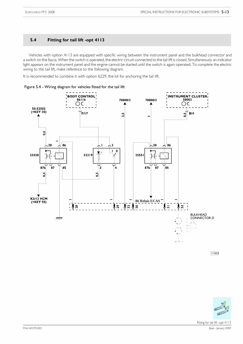
5.4 Fitting for tail lift -opt 4113
Vehicles with option 4113 are equipped with specific wiring between the instrument panel and the bulkhead connector anda switch on the fascia.When the switch is operated, the electric circuit connected to the tail lift is closed. Simultaneously an indicatorlight appears on the instrument panel and the engine cannot be started until the switch is again operated. To complete the electricwiring to the tail lift, make reference to the following diagram.
It is recommended to combine it with option 6229, the kit for anchoring the tail lift.
117653
BULKHEADCONNECTOR D
Figure 5.4 - Wiring diagram for vehicles fitted for the tail lift
86 Relais ECAS
5-14 SPECIAL INSTRUCTIONS FOR ELECTRONIC SUBSYSTEMS EUROCARGO M.Y. 2008
Base - January 2009 Print 603.95.003
Fitting for tail lift + 2nd ECAS remote control - opt 4115
Fitting for tail l ift + 2nd ECAS remote control --- opt 4115
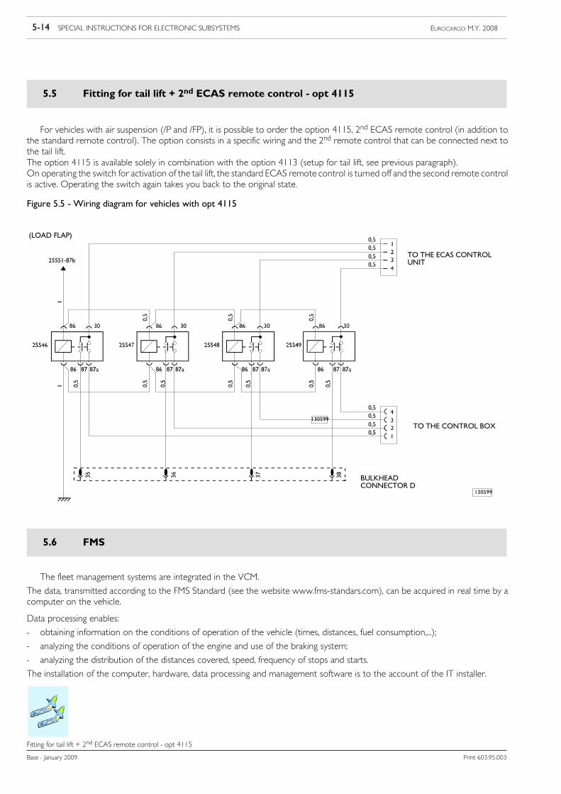
5.5 Fitting for tail lift + 2nd ECAS remote control - opt 4115
For vehicles with air suspension (/P and /FP), it is possible to order the option 4115, 2nd ECAS remote control (in addition tothe standard remote control). The option consists in a specific wiring and the 2nd remote control that can be connected next tothe tail lift.The option 4115 is available solely in combination with the option 4113 (setup for tail lift, see previous paragraph).On operating the switch for activation of the tail lift, the standard ECAS remote control is turned off and the second remote controlis active. Operating the switch again takes you back to the original state.
Figure 5.5 - Wiring diagram for vehicles with opt 4115
BULKHEADCONNECTOR D
130599
TO THE ECAS CONTROLUNIT
TO THE CONTROL BOX
130599
(LOAD FLAP)
5.6 FMS
The fleet management systems are integrated in the VCM.
The data, transmitted according to the FMS Standard (see the website www.fms-standars.com), can be acquired in real time by acomputer on the vehicle.
Data processing enables:
- obtaining information on the conditions of operation of the vehicle (times, distances, fuel consumption,...);
- analyzing the conditions of operation of the engine and use of the braking system;
- analyzing the distribution of the distances covered, speed, frequency of stops and starts.
The installation of the computer, hardware, data processing and management software is to the account of the IT installer.
SPECIAL INSTRUCTIONS FOR ELECTRONIC SUBSYSTEMS 5-15EUROCARGO M.Y. 2008
Print 603.95.003 Base - January 2009
EM (Expansion Module)
EM (Expansion Module)
5.7 EM (Expansion Module)
Available on all new Eurocargo vehicles there is option 4572, EM (Expansion Module).
The EM control unit can be used for electric PTO control and for special applications. In addition, it provides special gateways suchas: the trailer interface ISO11992-3 (TT) and the CAN OPEN interface.
Fault diagnosis is possible via CAN line and K line.
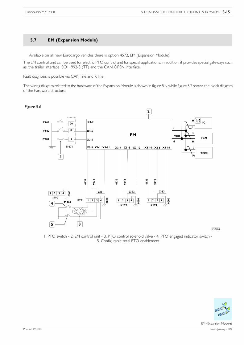
The wiring diagram related to the hardware of the Expansion Module is shown in figure 5.6, while figure 5.7 shows the block diagramof the hardware structure.
130600
Figure 5.6
1. PTO switch - 2. EM control unit - 3. PTO control solenoid valve - 4. PTO engaged indicator switch -5. Configurable total PTO enablement.
5-16 SPECIAL INSTRUCTIONS FOR ELECTRONIC SUBSYSTEMS EUROCARGO M.Y. 2008
Base - January 2009 Print 603.95.003
EM (Expansion Module)
130601
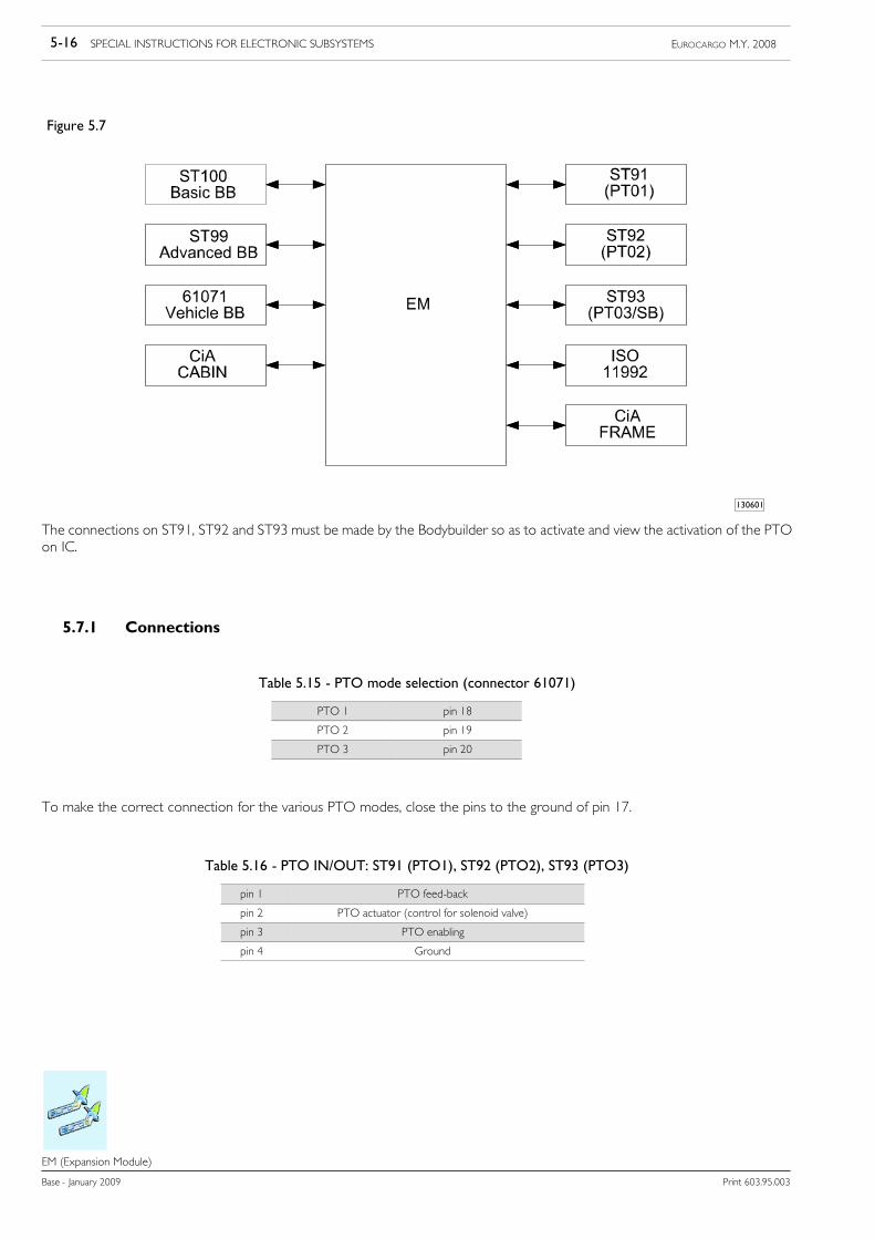
Figure 5.7
The connections on ST91, ST92 and ST93 must be made by the Bodybuilder so as to activate and view the activation of the PTOon IC.
5.7.1 Connections
Table 5.15 - PTO mode selection (connector 61071)
PTO 1 pin 18
PTO 2 pin 19
PTO 3 pin 20
To make the correct connection for the various PTO modes, close the pins to the ground of pin 17.
Table 5.16 - PTO IN/OUT: ST91 (PTO1), ST92 (PTO2), ST93 (PTO3)
pin 1 PTO feed-back
pin 2 PTO actuator (control for solenoid valve)
pin 3 PTO enabling
pin 4 Ground
SPECIAL INSTRUCTIONS FOR ELECTRONIC SUBSYSTEMS 5-17EUROCARGO M.Y. 2008
Print 603.95.003 Base - January 2009
EM (Expansion Module)
5.7.2 PTO on/off conditions:
The following conditions may be modified by IVECO Service.
Brake pedal status pressed / not pressed
Handbrake status engaged / not engaged
Clutch pedal status pressed / not pressed
Pressure switch status open/closed
Drive status neutral/not neutral/reverse drive
Group of permissible gears
Permissible engine speeds
Permissible vehicle speeds
Maximum coolant temperature
Maximum percentage of clutch slip
5.7.3 No PTO or PTO setups installed:
PREDEFINED CONFIGURATION
PTO Options: 5439, 5194, 6368, 1483, 1484.
Only engine speed programming by VCM is required.The switches select the three PTO modes:
Table 5.17
PTO 1 PTO mode 1 900 [rpm]
PTO 2 PTO mode 2 1100 [rpm]
PTO 3 PTO mode 3 1300 [rpm]
5.7.4 PTO Multipower
PREDEFINED CONFIGURATION
PTO Option: 2395 for all gearboxes.
The following conditions may be modified by IVECO Service.
Table 5.18 - Conditions of activation
Engine status OFF
Pressure switch closed
Vehicle status stationary
Coolant temperature < 120 [°C]
Table 5.19 - Conditions of deactivation
Vehicle status not stationary (PTO3)
Vehicle speed > 25 [km/h]
Coolant temperature > 120 [°C]

5-18 SPECIAL INSTRUCTIONS FOR ELECTRONIC SUBSYSTEMS EUROCARGO M.Y. 2008
Base - January 2009 Print 603.95.003
EM (Expansion Module)
5.7.5 Manual transmission PTO with electrical engagement
PREDEFINED CONFIGURATION
PTO Option: 6392, 6393, 1459, 1505, 1507, 1509, 6384, 14553, 14554 for all manual gearboxes.
The following conditions may be modified by IVECO Service.
Table 5.20 - Conditions of activation
Engine status ON
Clutch pedal status pressed
Vehicle status stationary
Coolant temperature < 120 [°C]
Table 5.21 - Conditions of deactivation
Engine status OFF
Vehicle status not stationary (PTO3)
Vehicle speed > 25 [km/h] (PTO1, PTO2)
Coolant temperature > 120 [°C]
5.7.6 Allison transmission PTO
PREDEFINED CONFIGURATION
Allison automatic transmission option: 8292 (PTO included)
The following conditions may be modified by IVECO Service.
Table 5.22 - Conditions of activation
Engine status ON (500 < rpm < 900)
Gearbox status neutral
Vehicle status stationary or reduced speed(0 < v < 2 [km/h])
Coolant temperature < 120 [°C]
Table 5.23 - Conditions of deactivation
Engine status OFF
Vehicle speed > 20 [km/h]
Coolant temperature > 120 [°C]
SPECIAL INSTRUCTIONS FOR ELECTRONIC SUBSYSTEMS 5-19EUROCARGO M.Y. 2008
Print 603.95.003 Base - January 2009
Electrical system: modifications and drawing-off power
Electrical system: modifications and drawing---off power
5.8 Electrical system: modifications and drawing-off power
5.8.1 General Information
The vehicles are fitted for operation with a 24V electric system for normal use, the chassis frame stands for ground (it acts asa current return conductor between the components situated on it and the source of energy, batteries/alternator), it is connectedto the negative pole of the batteries and components, if there is not an isolated return for this.
The installation of auxiliary equipment or circuits added by the Bodybuilder must take account of the following indications. Depend-ing on the complexity of the work, there must be suitable documentation (e.g. wiring diagram) to be included together with thatof the vehicle.
Using the same colours/codes for the cables and connections as those used on the original vehicle makes the installation more cor-rect and facilitates any repair operations.
Precautions
The vehicles are equipped with sophisticated electric/electronic systems that control their operation.
Work on the system (e.g. removing set of wiring, construction of additional circuits, replacing equipment, fuses, etc.) not done incompliance with IVECO directions or done by unqualified personnel can cause serious damage to the vehicle’s systems (controlunits, wirings, sensors, etc.), jeopardizing driving safety, proper operation of the vehicle and causing significant damage (e.g. shortcircuits with possible fire and destruction of the vehicle) not covered by contractual warranty.
No modifications or connections are allowed to the data connection line between control units (CAN line), where any change isstrictly prohibited. Any troubleshooting and maintenance operations can be carried only by authorised personnel, with IVECO ap-proved equipment.
It is always necessary to isolate the batteries before doing any work on the electric system, disconnecting the power cables, firstthe negative pole then the positive one.
Use fuses with the prescribed capacity for the specific function, never use fuses of greater capacity; make the replacement with keysand services disconnected, only after eliminating the trouble.
Restore the original conditions of the wirings (routes, protection, clamps, absolutely preventing the cable from coming into contactwith metal surfaces of the structure that can affect its integrity) if any work has been done on the system.
For work on the chassis frame, to protect the electric system, its appliances and the ground connections, respect the precautionsstated in points 2.1.1 and 2.3.4.
5-20 SPECIAL INSTRUCTIONS FOR ELECTRONIC SUBSYSTEMS EUROCARGO M.Y. 2008
Base - January 2009 Print 603.95.003
Electrical system: modifications and drawing-off power
In addition, definitely respect the following precautions for the protection of the vehicle’s electronic components:
Never disconnect the connectors of the control units with the engine running and control units powered.
Do not power the components interlocked with electronic modules with the vehicle’s nominal voltage via movable cables.
The control units provided with a metal casing must be connected to the ground of the system with screws or bolts, unless specifiedotherwise.
When required by the application of additional equipment, it is necessary to install diodes to protect against any inductive surgesin current.
The ground signal from the analogue sensors must be wired solely on the specific receiver; further ground connections could distortthe output signal from these sensors.
The bundle of cables for electronic components with low signal strength must be arranged in parallel to the metal surface of refer-ence, that is sticking to the chassis frame/cab structure, in order to reduce the parasite capacities to a minimum; separate the routeof the bundle of cables added to the existing one as far as possible.
The added systems must be connected to the ground of the systemwith the greatest care (see point 2.1.1); the related wirings mustnot be set alongside the existing electronic circuits on the vehicle, so as to avoid electromagnetic interference.
Make sure that the wirings of the electronic devices (length, type of conductor, location, clamps, connection of the shielding, etc.)are in compliance with the original IVECO setup. Carefully restore the original system after doing any work.
5.8.2 Electromagnetic Compatibility
It is recommended to use electric, electromechanical and electronic appliances that meet the prescriptions of electromagneticemission and immunity at both the radiated and carried level, described below:
At a distance of one metre from the transmitting antenna there must be:
- immunity of 50V/m for devices that perform secondary functions (they do not impact the direct control of the vehicle), for vari-able frequencies from 20 MHz to 2 GHz
- immunity of 100V/m for devices that perform primary functions (they impact the direct control of the vehicle), for variable -fre-quencies from 20 MHz to 2 GHz.
The maximum permissible amplitude of the transitory voltage for equipment powered at 24V is +80V measured at the terminalsof the artificial network (L.I.S.N.) if bench tested, otherwise if tested on the vehicle it must be measured at the most accessible pointnear to the interfering device.
NOTE Thedevices suppliedat 24Vmust be immune to negative interference suchas spikes of -600V, positivespikes of +100V, bursts of ± 200V.
They must work correctly during the phases of lowering the voltage to 8V for 40mS and to 0V for2 ms.
In addition they must withstand the phenomenon of load dumping to values of 58V.
The maximum levels measured at the bench of the radiated and carried emissions produced both by the devices and at 24V aregiven in the following Table 5.24.
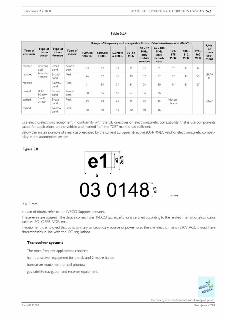
SPECIAL INSTRUCTIONS FOR ELECTRONIC SUBSYSTEMS 5-21EUROCARGO M.Y. 2008
Print 603.95.003 Base - January 2009
Electrical system: modifications and drawing-off power
Table 5.24
Range of frequency and acceptable limits of the interference in dBuV/mUnit
Type ofemission
Type oftrans-ducer
Type ofinter-ference
Type ofsensor 150KHz
300KHz530KHz2 MHz
5.9MHz6.2MHz
30 -54MHz
68 - 87MHzonlymobileservices
76 - 108MHzonlybroad-cast
142-175MHz
380 -512MHz
820 -960MHz
Unitof
measure-ment
radiated Antennaposi-ti d t
Broad-band
Almostpeak
63 54 35 35 24 24 24 31 37
radiated
ptioned at1 metre
Broad-band
Peak76 67 48 48 37 37 37 44 50
dBuV/m
radiated Narrow-band
Peak41 34 34 34 24 30 24 31 37
carried LISN50 ohm5 H/
Broad-band
Almostpeak
80 66 52 52 36 36
carried 5 uH/0.11uF
Broad-band
Peak93 79 65 65 49 49
Not ap-plicable
dBuV
carried Narrow-band
Peak70 50 45 40 30 36
p
Use electric/electronic equipment in conformity with the UE directives on electromagnetic compatibility; that is use componentssuited for applications on the vehicle and marked ”e.”, the ”CE” mark is not sufficient.
Below there is an example of amark as prescribed by the current European directive 2004/104EC valid for electromagnetic compati-bility in the automotive sector:
Figure 5.8
114476
a ≥ 6 mm
In case of doubt, refer to the IVECO Support network.
These levels are assured if the device comes from ”IVECO spare parts” or is certified according to the related international standardssuch as ISO, CISPR, VDE, etc....
If equipment is employed that as its primary or secondary source of power uses the civil electric mains (220V AC), it must havecharacteristics in line with the IEC regulations.
Transceiver systems
The most frequent applications concern:
- ham transceiver equipment for the cb and 2 metre bands;
- transceiver equipment for cell phones;
- gps satellite navigation and receiver equipment.
5-22 SPECIAL INSTRUCTIONS FOR ELECTRONIC SUBSYSTEMS EUROCARGO M.Y. 2008
Base - January 2009 Print 603.95.003
Electrical system: modifications and drawing-off power
Choosing an antenna installation is of considerable importance to assure the transceiver apparatus the greatest performance. It mustbe of excellent quality and installed with the greatest care, also the position in which it is fixed is of fundamental importance; it deter-mines the efficiency of the antenna and therefore the capacity of the transmission.
Therefore the characteristics of SWR (StandingWave Ratio), gain and electromagnetic field generatedmust be assuredwithin certainlimits, while the parameters of impedance, effective height, efficiency and directivity are deduced from the manufacturer’s technicalinformation sheet.
The installation of c.b. ham 2m appliances, mobile phones (gsm) and satellite navigation systems (GPS) must use the supply systemalready set up on the vehicle, making the connection directly to terminal 30 of connector ST40 (and 15 where necessary).
This equipment must be type approved according to the law and be the fixed type (not portable). Using transceivers that have notbeen type approved or applying additional amplifiers could seriously jeopardize the correct operation of the electric/electronic de-vices normally supplied, with negative effects on the safety of the vehicle and/or of the driver.
CB and 2m band ham radio appliances
The installation of C.B. (27 MHz), 2m (144 MHz) appliances must use the supply system already set up on the vehicle, makingthe connection to terminal 30 of connector ST40.
This equipment must be type approved according to the law and be the fixed type (not portable). Install the transmitting part ina flat and dry zone separated from the electronic components of the vehicle sheltered from moisture and vibration.
The antenna must be installed outside the vehicle, preferably on a large metal base fitted as vertically as possible with the connectingcable turned downwards, observing the assembly prescriptions and the instructions of the manufacturer (see Figure 5.9).
• The value of the SWR must be as near as possible to unity, the recommended value is 1.5 while the maximum acceptable valuemust in no case be greater than 2.
• The values of the ANTENNA GAINmust be as high as possible and assure a sufficient characteristic of spatial uniformity, char-acterized by deviations from the mean in the order of 1.5dB in the typical cb band (26.965-27.405 MHz).
• The value of the RADIATED FIELD IN THE CAB must be as low as possible, as a quality objective we recommend < 1V/m.In any case the limits set by the current European directive must not be exceeded.
• For this reason the antenna must be always be set outside the cab.
To determine proper operation of the radio-cable-antenna system and allow evaluating whether the antenna is calibrated, it is rec-ommended to take account of the following indications:
1) if the SWR is higher on the low channels than on the high ones it is necessary to lengthen the antenna;
2) if the SWR is higher on the high channels than on the lower ones it is necessary to shorten the antenna.
After calibrating the antenna it is advisable to recheck the value of the SWR on all the channels.
Installation in the middle of the roof is considered the best since the ground surface is proportional in every direction, while assemblyon a side or on any other part of the vehicle makes the ground surface proportional to its ground.
The connection and positioning of the cables that involve the installations must be done taking care to:
- use a coaxial antenna cable of excellent quality with low loss and having the same impedance as the transmitter and the antenna(see Figure 5.10);
- for the aforesaid coaxial cable make a route that, so as to avoid interference and malfunctioning, has a suitable distance(min. 50 mm) from the pre-existing wiring and from other cables (TV, Radio, Telephone, Amplifiers and other electronic equip-ment), saving the minimum distance from the metal structure of the cab; application is preferable on the left or right side;
- when installing the fixed antenna it is necessary to clean the bottom of the hole made in the bodywork, so that the antennasupport is properly connected to the ground of the vehicle;
- the coaxial cable joining the antenna to the radio must be mounted with great care, it is necessary to avoid bends or folds thatcan crush or deform. If the cable is too long, avoid pointless tangles, and preferably shorten it as much as possible. It is wise toremember that any imperfection in the coaxial cable always causes serious trouble for the transceiver;

SPECIAL INSTRUCTIONS FOR ELECTRONIC SUBSYSTEMS 5-23EUROCARGO M.Y. 2008
Print 603.95.003 Base - January 2009
Electrical system: modifications and drawing-off power
- for the cable passage use the existing holes; if necessary and essential make an additional hole; take the precautions to preservethe bodywork (rustproofing, liner, etc..);
- assure a good connection with the structure of the vehicle (ground), both of the base of the antenna and of the containers ofthe appliances, to achieve the maximum transfer of power.
The typical installation positions of transceiver equipment are those of the dashboard-gearbox or roof assembly zone - driver side(see Figure 5.11).
The electric supply of the appliances, if requiring a different voltage to that of the system, must be obtained via a suitableDC/DC 24-12V converter if not already contemplated. The supply cables must be as short as possible, avoiding any coils (twisting)and observing the minimum distance from the reference surface.
Figure 5.9
1. Antenna support - 2. Gasket (code for spare parts 244614) - 3. Cap covering fixed joint (spare parts code 217522) -4. Retaining bolt M6x8.5 (screw on with a tightening torque of 2 Nm) - 5. Antenna (spare parts code of the rod
assembly 675120) - 6. Roof assembly - 7. Antenna extension cable
98915
Figure 5.10
1. Antenna connector - 2. Ground brush - 3. Insulation - 4. Signal brush - 5. Capacitor (100pF) - 6. Cable RG 58(characteristic impedance = 50 Ω) - 7. Clamp - 8. Protective cap - 9. Connector (N.C. SO -239) transceiver side -
10. Adhesive tape for testing performed - 11. The 100pF capacitor must be welded with the lower brush and crimpedwith the ground braid - 12. The lower brush must be welded to the internal conductor of the cable - 13. Nut
99349
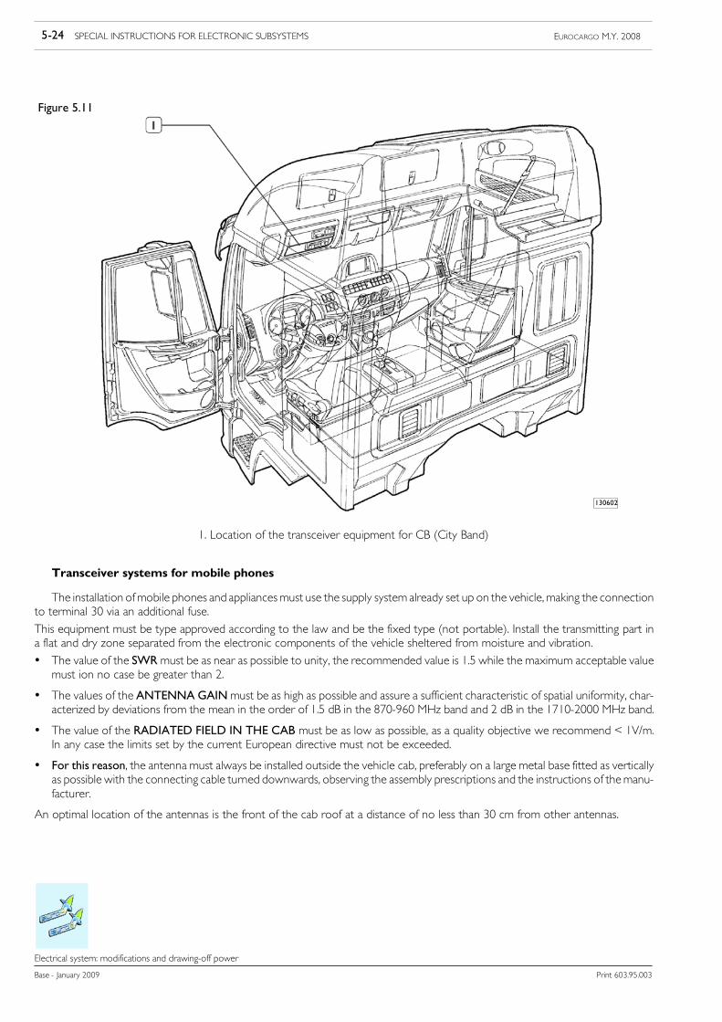
5-24 SPECIAL INSTRUCTIONS FOR ELECTRONIC SUBSYSTEMS EUROCARGO M.Y. 2008
Base - January 2009 Print 603.95.003
Electrical system: modifications and drawing-off power
Figure 5.11
1. Location of the transceiver equipment for CB (City Band)
130602
Transceiver systems for mobile phones
The installation ofmobile phones and appliancesmust use the supply system already set up on the vehicle,making the connectionto terminal 30 via an additional fuse.
This equipment must be type approved according to the law and be the fixed type (not portable). Install the transmitting part ina flat and dry zone separated from the electronic components of the vehicle sheltered from moisture and vibration.
• The value of the SWRmust be as near as possible to unity, the recommended value is 1.5 while the maximum acceptable valuemust ion no case be greater than 2.
• The values of the ANTENNA GAINmust be as high as possible and assure a sufficient characteristic of spatial uniformity, char-acterized by deviations from the mean in the order of 1.5 dB in the 870-960 MHz band and 2 dB in the 1710-2000 MHz band.
• The value of the RADIATED FIELD IN THE CAB must be as low as possible, as a quality objective we recommend < 1V/m.In any case the limits set by the current European directive must not be exceeded.
• For this reason, the antenna must always be installed outside the vehicle cab, preferably on a large metal base fitted as verticallyas possible with the connecting cable turned downwards, observing the assembly prescriptions and the instructions of themanu-facturer.
An optimal location of the antennas is the front of the cab roof at a distance of no less than 30 cm from other antennas.

SPECIAL INSTRUCTIONS FOR ELECTRONIC SUBSYSTEMS 5-25EUROCARGO M.Y. 2008
Print 603.95.003 Base - January 2009
Electrical system: modifications and drawing-off power
The connection and positioning of the cables that involve the installations must be done taking care to:
- use a good quality antenna cable, particularly for the effects of visual coverage of the protective screen;
- for the aforesaid cable make a route that has a suitable distance (min. 50 mm) from the pre-existing wiring, saving the minimumdistance from the metal structure of the cab, taking care that the cable is not too taut and preventing the cable getting foldedand crushed; application is preferable on the left or right side;
- never shorten or lengthen the coaxial antenna cable;
- use the existing holes for the cable passage. If necessary and essential make an additional hole; take the precautions to preservethe bodywork (rustproofing, liner, etc..);
- assure a good connection with the structure of the vehicle (ground), both of the base of the antenna and of the containers ofthe appliances, to achieve the maximum transfer of power.
The typical installation positions of equipment are those of the dashboard-gearbox or roof assembly zone - driver side.
The electric supply of the appliances, if requiring a different voltage to that of the system, must be obtained via a suitableDC/DC 24-12V converter if not already contemplated. The supply cables must be as short as possible, avoiding any coils (twisting)and observing the minimum distance from the reference surface.
Installations of GPS antenna cables and navigation receiving equipment
Correct and careful assembly of the GPS antennas on the vehicle is extremely important to accomplish correct operation andobtain top performance.
The antennas must be mounted, preferably, in hidden places, out of sight.The position of the GPS antenna is delicate. The signal levels received from the satellite have very low power (approximately136 dBm), so that any obstacle for the antenna can affect the quality and performance of the receiver.
• The value of the SWRmust be as near as possible to unity, the recommended value is 1.5 while the maximum acceptable valuemust in no case be greater than 2 in the GPS frequency range (1575.42 ±1.023 MHz).
• The values of the ANTENNA GAINmust be as high as possible and assure a sufficient characteristic of spatial uniformity, char-acterized by deviations from the mean in the order of 1.5 dB in the band 1575.42 ±1.023 MHz.
The GPS antenna must be installed in such a way that it has the greatest possible view of the sky.It is recommended to have 90° as the absolute minimum angle of vision of the sky. This view of the sky must not be obscured byany object or metal structure. The position has to be Horizontal.An ideal location for the GPS antenna is under the plastic dashboard in the centre and at the base of the vehicle’s windscreen.It must not be installed below any metal that belongs to the cab structure.
Position the GPS antenna at a distance of no less than 30 cm from another antenna.The connection and positioning of the cables that involve the installations must be done taking care to:
- use a good quality antenna cable, particularly for the effects of visual coverage of the protective screen;
- for the aforesaid cable make a route that has a suitable distance (min. 50 mm) from the pre-existing wiring, saving the minimumdistance from the metal structure of the cab, taking care that the cable is not too taut and preventing the cable getting foldedand crushed; application is preferable on the left or right side;
- never shorten or lengthen the coaxial antenna cable;
- use the existing holes for the cable passage. If necessary and essential make an additional hole; take the precautions to preservethe bodywork (rustproofing, liner, etc..);
- assure a good connection with the structure of the vehicle (ground), both of the base of the antenna and of the containers ofthe appliances, to achieve the maximum transfer of power.
The installation of navigator appliances must use the supply system already set up on the vehicle, making the connection to ter-minal 30 via an additional fuse.
This equipment must be type approved according to the law and be the fixed type (not portable). Install the transmitting part ina flat and dry zone separated from the electronic components of the vehicle sheltered from moisture and vibration.
5-26 SPECIAL INSTRUCTIONS FOR ELECTRONIC SUBSYSTEMS EUROCARGO M.Y. 2008
Base - January 2009 Print 603.95.003
Electrical system: modifications and drawing-off power
The electric supply of the appliances, if requiring a different voltage to that of the system, must be obtained via a suitable DC/DC24-12V converter if not already contemplated. The supply cables must be as short as possible, avoiding any coils (twisting) and ob-serving the minimum distance from the reference surface.
!In caseof installationof devices that can interactwithother electronic systems suchas:Retarders,addi-tional heaters, power take-offs, air conditioners, automatic gearboxes, Telematics and speed limiters,contact IVECO in order to optimize the application.
For operations that could cause interferencewith the standard system, it is necessaryto performdiagnos-tic checks in order to ensure correct assembly of the system. These checks can be made using the diag-nostic ECUs [Electronic Control Units] on the vehicle or the IVECO service.
IVECO reserves the right to have warranty on the vehicle elapse if any work not conforming to itsdirectives is carried out.
NOTE
5.8.3 Additional equipment
The vehicle system is designed to supply the necessary power to the equipment provided, for each piece of which, within itsrespective function, the specific protection and the correct sizing of the cables are ensured.
The application of additional equipment must make provision for suitable protection and must not overload the vehicle’s system.
The connection to ground of the added services must be made with a cable of suitable cross-section, as short as possible and madeso as to allow movement of the added equipment in relation to the vehicle’s chassis frame.
Needing batteries of greater capacity, for the demands of added loads, it is wise to request the option with uprated batteries andalternators.
In any case it is recommended not to exaggerate in increasing the capacity of the batteries over 20-30% of the maximum valuessupplied as an option by IVECO, so as not to damage any components of the system (e.g. starter motor). When higher capacitiesare necessary, use additional batteries, taking the necessary precautions for recharging, as indicated below.
Additional batteries and alternators
The installation of electric appliances with a high power input (e.g. electric motors operated often or even more rarely for longperiods and without using the vehicle’s engine, such as the tail lifts), or a large number of additional electrical appliances can requirepowers that the vehicle’s normal system is not able to deliver. In these cases additional batteries of suitable capacities must be used.
Their insertion in the vehicle’s circuit must make provision for a separate recharging system (see Figure 5.12) integrated with thatof the vehicle. In this case it is a good rule to use additional batteries of the same capacity as the ones originally mounted in orderto recharge all the batteries correctly.
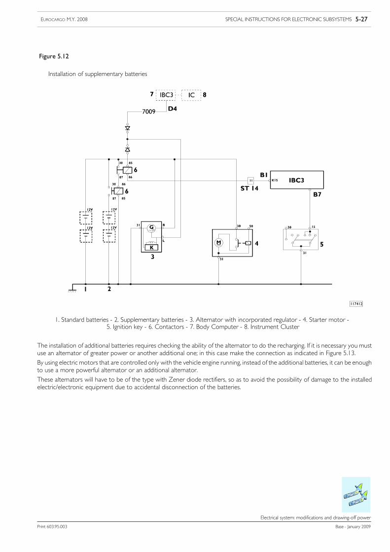
SPECIAL INSTRUCTIONS FOR ELECTRONIC SUBSYSTEMS 5-27EUROCARGO M.Y. 2008
Print 603.95.003 Base - January 2009
Electrical system: modifications and drawing-off power
Installation of supplementary batteries
Figure 5.12
1. Standard batteries - 2. Supplementary batteries - 3. Alternator with incorporated regulator - 4. Starter motor -5. Ignition key - 6. Contactors - 7. Body Computer - 8. Instrument Cluster
117412
The installation of additional batteries requires checking the ability of the alternator to do the recharging. If it is necessary you mustuse an alternator of greater power or another additional one; in this case make the connection as indicated in Figure 5.13.
By using electric motors that are controlled only with the vehicle engine running, instead of the additional batteries, it can be enoughto use a more powerful alternator or an additional alternator.
These alternators will have to be of the type with Zener diode rectifiers, so as to avoid the possibility of damage to the installedelectric/electronic equipment due to accidental disconnection of the batteries.
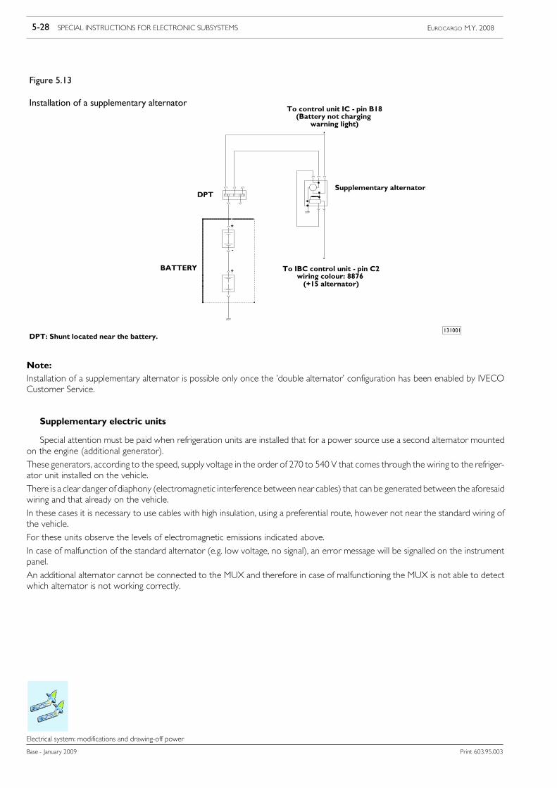
5-28 SPECIAL INSTRUCTIONS FOR ELECTRONIC SUBSYSTEMS EUROCARGO M.Y. 2008
Base - January 2009 Print 603.95.003
Electrical system: modifications and drawing-off power
Installation of a supplementary alternator
Figure 5.13
131001
Supplementary alternator
To IBC control unit - pin C2wiring colour: 8876(+15 alternator)
BATTERY
To control unit IC - pin B18(Battery not charging
warning light)
DPT
DPT: Shunt located near the battery.
Note:Installation of a supplementary alternator is possible only once the ’double alternator’ configuration has been enabled by IVECOCustomer Service.
Supplementary electric units
Special attention must be paid when refrigeration units are installed that for a power source use a second alternator mountedon the engine (additional generator).
These generators, according to the speed, supply voltage in the order of 270 to 540 V that comes through the wiring to the refriger-ator unit installed on the vehicle.
There is a clear danger of diaphony (electromagnetic interference between near cables) that can be generated between the aforesaidwiring and that already on the vehicle.
In these cases it is necessary to use cables with high insulation, using a preferential route, however not near the standard wiring ofthe vehicle.
For these units observe the levels of electromagnetic emissions indicated above.
In case of malfunction of the standard alternator (e.g. low voltage, no signal), an error message will be signalled on the instrumentpanel.
An additional alternator cannot be connected to the MUX and therefore in case of malfunctioning the MUX is not able to detectwhich alternator is not working correctly.
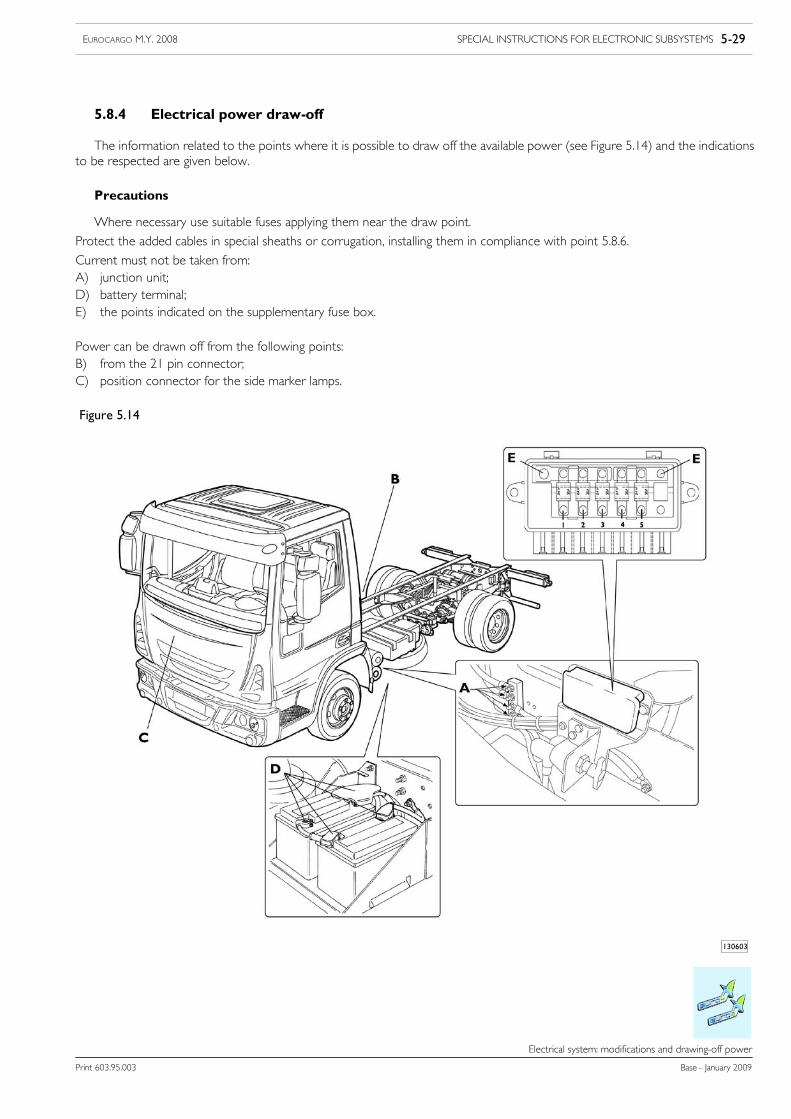
SPECIAL INSTRUCTIONS FOR ELECTRONIC SUBSYSTEMS 5-29EUROCARGO M.Y. 2008
Print 603.95.003 Base - January 2009
Electrical system: modifications and drawing-off power
5.8.4 Electrical power draw-off
The information related to the points where it is possible to draw off the available power (see Figure 5.14) and the indicationsto be respected are given below.
Precautions
Where necessary use suitable fuses applying them near the draw point.
Protect the added cables in special sheaths or corrugation, installing them in compliance with point 5.8.6.
Current must not be taken from:A) junction unit;D) battery terminal;E) the points indicated on the supplementary fuse box.
Power can be drawn off from the following points:B) from the 21 pin connector;C) position connector for the side marker lamps.
Figure 5.14
130603
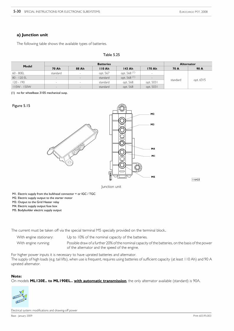
5-30 SPECIAL INSTRUCTIONS FOR ELECTRONIC SUBSYSTEMS EUROCARGO M.Y. 2008
Base - January 2009 Print 603.95.003
Electrical system: modifications and drawing-off power
a) Junction unit
The following table shows the available types of batteries.
Table 5.25
ModelBatteries Alternator
Model70 Ah 88 Ah 110 Ah 143 Ah 170 Ah 70 A 90 A
60 - 80EL standard - opt. 567 opt. 568 (1) -
80 - 120 EL - - standard opt. 568 (1) -standard opt 6315
120 - 190 - - standard opt. 568 opt. 5031standard opt. 6315
110W - 150W - - standard opt. 568 opt. 5031
(1) no for wheelbase 3105 mechanical susp.
Figure 5.15
Junction unit
M1. Electric supply from the bulkhead connector + or IGC / TGCM2. Electric supply output to the starter motorM3. Output to the Grid Heater relayM4. Electric supply output fuse boxM5. Bodybuilder electric supply output
116423
The current must be taken off via the special terminal M5 specially provided on the terminal block..
With engine stationary: Up to 10% of the nominal capacity of the batteries.
With engine running: Possible draw of a further 20%of the nominal capacity of the batteries, on the basis of the powerof the alternator and the speed of the engine.
For higher power inputs it is necessary to have uprated batteries and alternator.The supply of high loads (e.g. tail lifts), when use is frequent, requires using batteries of sufficient capacity (at least 110 Ah) and 90 Auprated alternator.
Note:On models ML120E.. to ML190EL.. with automatic transmission, the only alternator available (standard) is 90A.
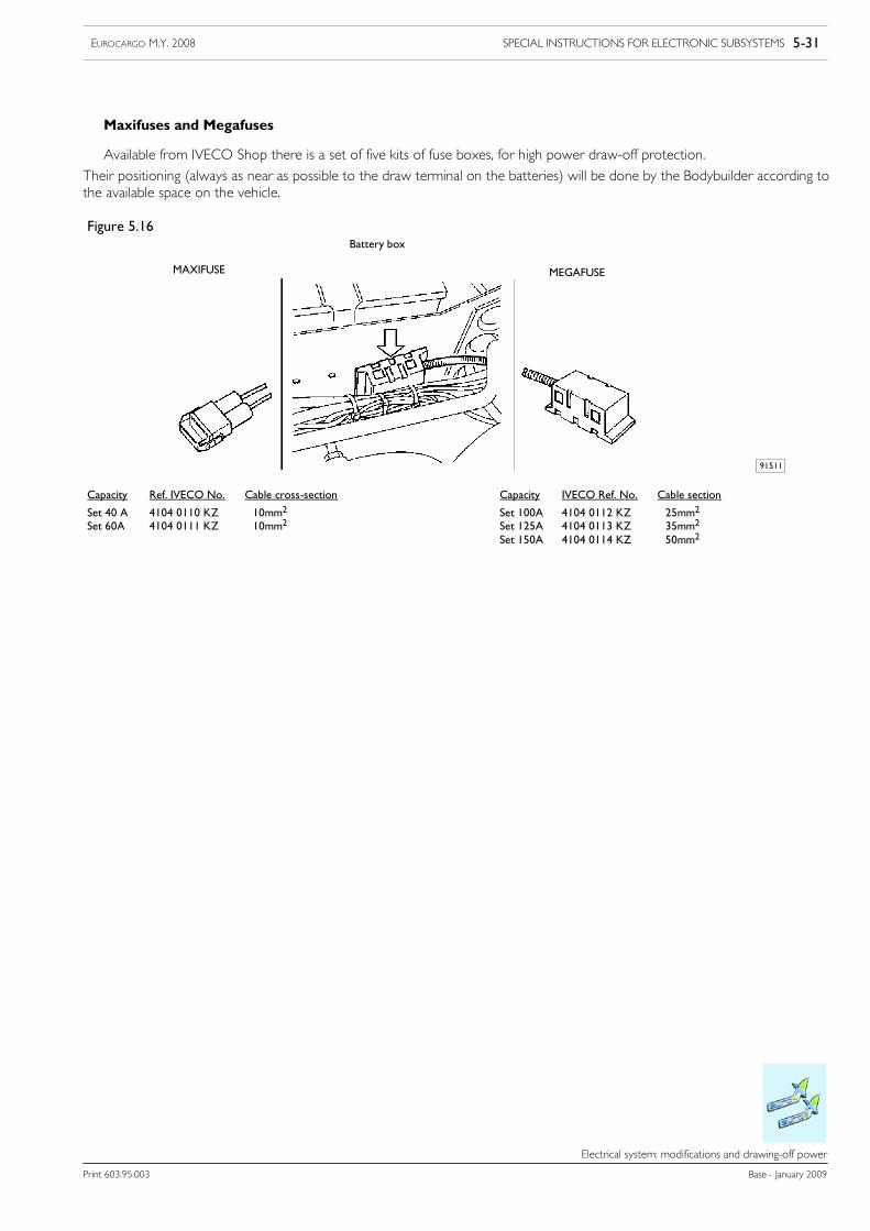
SPECIAL INSTRUCTIONS FOR ELECTRONIC SUBSYSTEMS 5-31EUROCARGO M.Y. 2008
Print 603.95.003 Base - January 2009
Electrical system: modifications and drawing-off power
Maxifuses and Megafuses
Available from IVECO Shop there is a set of five kits of fuse boxes, for high power draw-off protection.
Their positioning (always as near as possible to the draw terminal on the batteries) will be done by the Bodybuilder according tothe available space on the vehicle.
Capacity IVECO Ref. No. Cable section
Set 100A 4104 0112 KZ 25mm2
Set 125A 4104 0113 KZ 35mm2
Set 150A 4104 0114 KZ 50mm2
Figure 5.16
Capacity Ref. IVECO No. Cable cross-section
Set 40 A 4104 0110 KZ 10mm2
Set 60A 4104 0111 KZ 10mm2
Battery box
MAXIFUSE MEGAFUSE
91511
5-32 SPECIAL INSTRUCTIONS FOR ELECTRONIC SUBSYSTEMS EUROCARGO M.Y. 2008
Base - January 2009 Print 603.95.003
Electrical system: modifications and drawing-off power
b) 21 pin connector 61071 (brown)
From the 21 pin connector, located in the electronic control unit compartment (under the panel at the bottomon the passengerside), it is possible to take current from pins 11 and 21.This current draw is protected by two fuses:
FUSES MAXIMUM LOAD DESCRIPTIONFUSES MAXIMUM LOAD DESCRIPTIONF9 10A K30 (pin 21)F15 3A K15 (pin 11)
For further details see point 5.2.
c) Connector for Side Marker Lamps
In someCountries the regulations (national or EC) require the outfitted vehicle to be providedwith sidemarker lamps, dependingon its overall length.
Vehicles in the Eurocargo Euro 4-5 Range are provided with a specific super seal type female connector to make the electric supplyconnection for the side lights.
Making the connections and installing the lights must be done by external Bodybuilders on the added structures (box-bodies, vans, etc.).
The positions of the aforesaid terminals are given below.
!In order to keep the electric characteristics of the contacts of the female connector unchanged overtime, it is important to leave the cap supplied by IVECO attached.
5.8.5 Main switch of the batteries (optional)
IGC (Master current switch):
It is mounted on the battery box and is manually controlled. It is the single pole type, its operation disconnects the battery fromthe vehicle’s system, leaving in operation the body computer, refrigerator,Webasto timer and, for requirements of the law, the tacho-graph.
TGC (Master current relay):
It is possible to close the circuit by opening the doors, with the ignition key, ignition of the ceiling lights, marker lamps, hazardlights, electric trap control, timer of the additional heater, the TGC ON button on the fascia.
For special outfits (e.g., haulage of fuel, dangerous goods, etc.), a specific switch is required to A.D.R. standard.
SPECIAL INSTRUCTIONS FOR ELECTRONIC SUBSYSTEMS 5-33EUROCARGO M.Y. 2008
Print 603.95.003 Base - January 2009
Electrical system: modifications and drawing-off power
5.8.6 Additional circuits
They must be separate and protected with a special fuse from the vehicle’s main circuit.
The added electric cables must be connected to the original electric systemwith watertight junctions equivalent to the original ones.The added cables must be protected in special sheaths (not PVC) or corrugated pipes appropriately fixed with brackets, protectedfrom bumps and sources of heat.
The cables must have a minimum distance of:
- 150 mm from sources of high heat (turbine, engine, exhaust manifold,...)
- 50 mm from containers of chemical agents (batteries, etc...)
- 20 mm from moving parts.
Take the utmost care to avoid any rubbing of the cables with other components and particularly with any sharp edges of the body-work.
The route of the cables must be defined as much as possible with dedicated brackets and clamps and moved closer (around 350 mm),to avoid hanging parts and provide the possibility (and obligation) to rebuild the same installation in the case of repairs or outfits.
The passage of cables in holes and on edges of various panels must be protected by cable glands (besides the covering of the corruga-tion). It is forbidden to perforate the chassis frame for the passage of the cables.
The corrugated pipe must protect the whole cable completely andmust be joined (with heat shrink sections or taping) to the rubbercaps on the terminals. In addition the corrugated pipe clamps (cut longitudinally) must not deform it, to avoid the cables being ableto come out or anyhow be in contact with the sharp edge of the pipe.
All the terminals (+) for connecting the aforesaid cables and their lugs must be protected by rubber caps, (airtight for zones exposedto the weather or with any stagnation of water).
The fastening of the lugs on the terminals (also negative) must be assured to avoid loosening, applying a tightening torque wherepossible and fanning out the lugs in the case of multiple connections (preferably to avoid).
It is wise where possible, to make provision for a different route for the cables passing between interfering high-intensity signals(e.g. electric motors, solenoid valves) and susceptible low-intensity signals (e.g. sensors) anyhow keeping for both a position as closeas possible to the metal structure of the vehicle.
In the case of chassis frame-tipping cab connection, the position of the set of wiring must be checked with the cab in its seat andtipped, to trace any interference and the tensioning to be corrected.
!Depending on the drawn current, use fuses and cables of suitable cross-section, as shown in theTable 5.26. The fuse must be connected as near as possible to the point of drawing off the current.
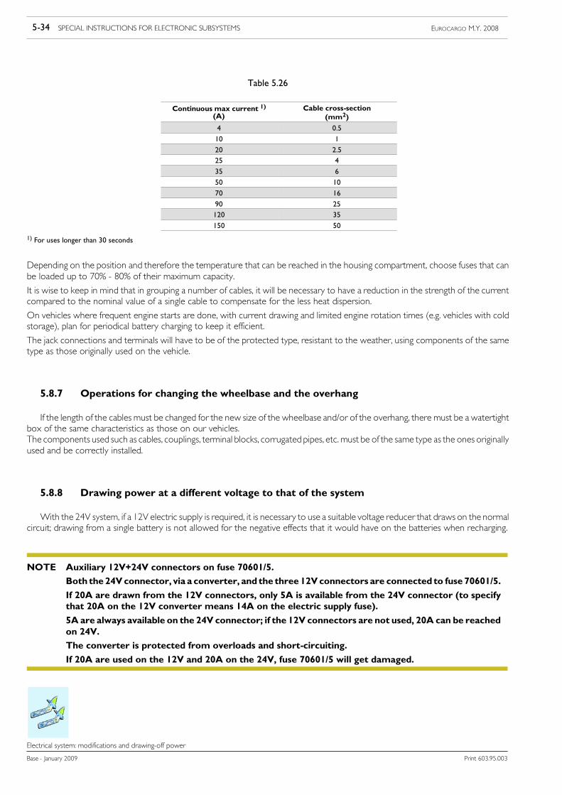
5-34 SPECIAL INSTRUCTIONS FOR ELECTRONIC SUBSYSTEMS EUROCARGO M.Y. 2008
Base - January 2009 Print 603.95.003
Electrical system: modifications and drawing-off power
Table 5.26
Continuous max current 1)(A)
Cable cross-section(mm2)
4 0.5
10 1
20 2.525 4
35 6
50 10
70 16
90 25120 35
150 50
1) For uses longer than 30 seconds
Depending on the position and therefore the temperature that can be reached in the housing compartment, choose fuses that canbe loaded up to 70% - 80% of their maximum capacity.
It is wise to keep in mind that in grouping a number of cables, it will be necessary to have a reduction in the strength of the currentcompared to the nominal value of a single cable to compensate for the less heat dispersion.
On vehicles where frequent engine starts are done, with current drawing and limited engine rotation times (e.g. vehicles with coldstorage), plan for periodical battery charging to keep it efficient.
The jack connections and terminals will have to be of the protected type, resistant to the weather, using components of the sametype as those originally used on the vehicle.
5.8.7 Operations for changing the wheelbase and the overhang
If the length of the cables must be changed for the new size of the wheelbase and/or of the overhang, there must be a watertightbox of the same characteristics as those on our vehicles.The components used such as cables, couplings, terminal blocks, corrugated pipes, etc. must be of the same type as the ones originallyused and be correctly installed.
5.8.8 Drawing power at a different voltage to that of the system
With the 24V system, if a 12V electric supply is required, it is necessary to use a suitable voltage reducer that draws on the normalcircuit; drawing from a single battery is not allowed for the negative effects that it would have on the batteries when recharging.
Auxiliary 12V+24V connectors on fuse 70601/5.
Both the24Vconnector, via a converter, and the three12Vconnectors are connected to fuse 70601/5.
If 20A are drawn from the 12V connectors, only 5A is available from the 24V connector (to specifythat 20A on the 12V converter means 14A on the electric supply fuse).
5A are always available on the 24V connector; if the 12V connectors are not used, 20A can be reachedon 24V.
The converter is protected from overloads and short-circuiting.
If 20A are used on the 12V and 20A on the 24V, fuse 70601/5 will get damaged.
NOTE
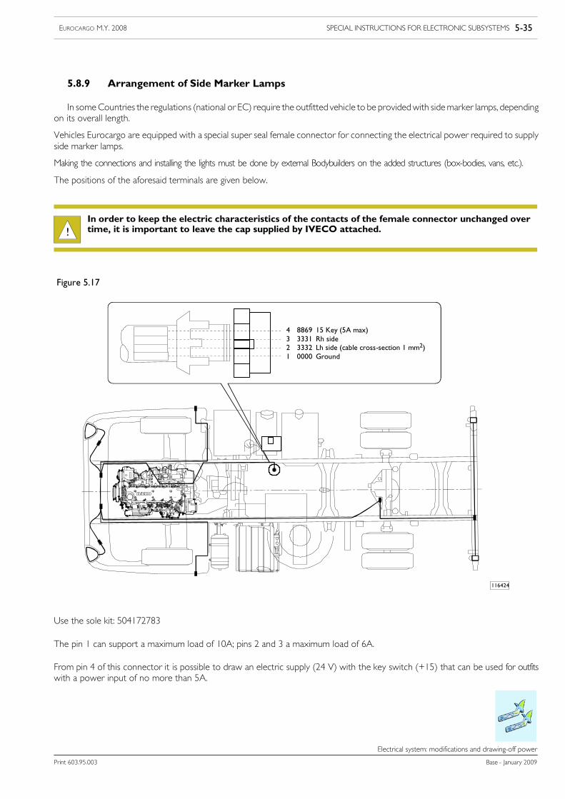
SPECIAL INSTRUCTIONS FOR ELECTRONIC SUBSYSTEMS 5-35EUROCARGO M.Y. 2008
Print 603.95.003 Base - January 2009
Electrical system: modifications and drawing-off power
5.8.9 Arrangement of Side Marker Lamps
In someCountries the regulations (national or EC) require the outfitted vehicle to be providedwith sidemarker lamps, dependingon its overall length.
Vehicles Eurocargo are equipped with a special super seal female connector for connecting the electrical power required to supplyside marker lamps.
Making the connections and installing the lights must be done by external Bodybuilders on the added structures (box-bodies, vans, etc.).
The positions of the aforesaid terminals are given below.
!In order to keep the electric characteristics of the contacts of the female connector unchanged overtime, it is important to leave the cap supplied by IVECO attached.
Figure 5.17
116424
4 8869 15 Key (5A max)3 3331 Rh side2 3332 Lh side (cable cross-section 1 mm2)1 0000 Ground
Use the sole kit: 504172783
The pin 1 can support a maximum load of 10A; pins 2 and 3 a maximum load of 6A.
From pin 4 of this connector it is possible to draw an electric supply (24 V) with the key switch (+15) that can be used for outfitswith a power input of no more than 5A.

SPECIAL INSTRUCTIONS FOR -SCR- EXHAUST SYSTEMS 6-1EUROCARGO M.Y. 2008
Print 603.95.003 Base - January 2009
Index
Index
SECTION 6
Special instructions for -SCR- exhaust system
Page
6.1 General specifications 6-3
6.2 The nitrogen oxide catalytic reduction principle. AdBlue 6-4
6.3 On-board instruments 6-7
6.4 Distribution of the ecological additive AdBlue 6-8
6.5 Specifications for installation and removal 6-9
6.5.1 Operations for positioning the AdBlue tank 6-9
6.5.2 Operations on AdBlue pipes and heating water 6-11
6.5.3 Altering the supply module position 6-17
6.5.4 Operations on the dosing module 6-21
6.5.5 Operations on exhaust pipes 6-24
6.6 Wiring for positioning of SCR system components 6-25
6.7 OBD 1 - Stage 2 6-26

6-2 SPECIAL INSTRUCTIONS FOR -SCR- EXHAUST SYSTEMS EUROCARGO M.Y. 2008
Base - January 2009 Print 603.95.003
Index
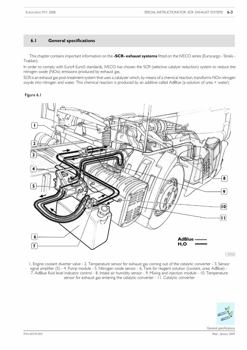
SPECIAL INSTRUCTIONS FOR -SCR- EXHAUST SYSTEMS 6-3EUROCARGO M.Y. 2008
Print 603.95.003 Base - January 2009
General specifications
6666.6
General specifications
6.1 General specifications
This chapter contains important information on the -SCR- exhaust systems fitted on the IVECO series (Eurocargo - Stralis -Trakker).
In order to comply with Euro4 Euro5 standards, IVECO has chosen the SCR (selective catalyst reduction) system to reduce thenitrogen oxide (NOx) emissions produced by exhaust gas.
SCR is an exhaust gas post-treatment system that uses a catalyzer which, by means of a chemical reaction, transforms NOx nitrogenoxyde into nitrogen and water. This chemical reaction is produced by an additive called AdBlue (a solution of urea + water).
Figure 6.1
1. Engine coolant diverter valve - 2. Temperature sensor for exhaust gas coming out of the catalytic converter - 3. Sensorsignal amplifier (5) - 4. Pump module - 5. Nitrogen oxide sensor - 6. Tank for reagent solution (coolant, urea: AdBlue) -7. AdBlue fluid level indicator control - 8. Intake air humidity sensor - 9. Mixing and injection module - 10. Temperature
sensor for exhaust gas entering the catalytic converter - 11. Catalytic converter
125526
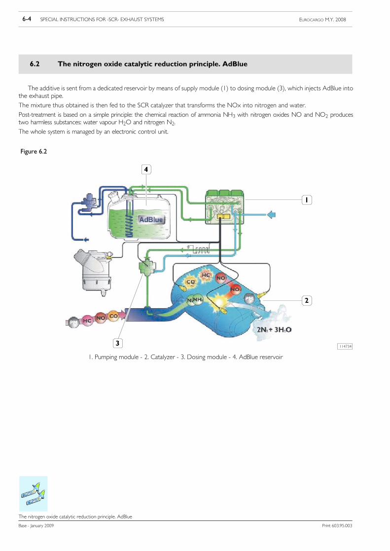
6-4 SPECIAL INSTRUCTIONS FOR -SCR- EXHAUST SYSTEMS EUROCARGO M.Y. 2008
Base - January 2009 Print 603.95.003
The nitrogen oxide catalytic reduction principle. AdBlue
The nitrogen oxide catalytic reduction principle. AdBlue
6.2 The nitrogen oxide catalytic reduction principle. AdBlue
The additive is sent from a dedicated reservoir by means of supply module (1) to dosing module (3), which injects AdBlue intothe exhaust pipe.
The mixture thus obtained is then fed to the SCR catalyzer that transforms the NOx into nitrogen and water.
Post-treatment is based on a simple principle: the chemical reaction of ammonia NH3 with nitrogen oxides NO and NO2 producestwo harmless substances: water vapour H2O and nitrogen N2.
The whole system is managed by an electronic control unit.
Figure 6.2
114734
1. Pumping module - 2. Catalyzer - 3. Dosing module - 4. AdBlue reservoir
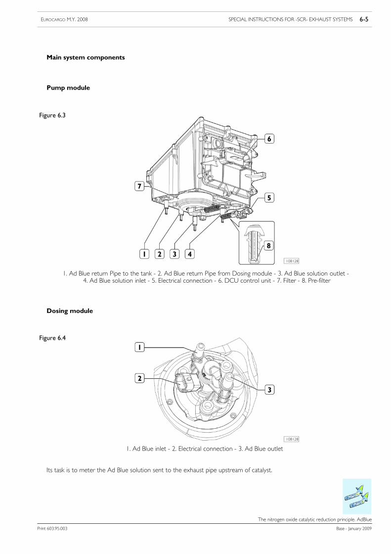
SPECIAL INSTRUCTIONS FOR -SCR- EXHAUST SYSTEMS 6-5EUROCARGO M.Y. 2008
Print 603.95.003 Base - January 2009
The nitrogen oxide catalytic reduction principle. AdBlue
Main system components
Pump module
Figure 6.3
108128
1. Ad Blue return Pipe to the tank - 2. Ad Blue return Pipe from Dosing module - 3. Ad Blue solution outlet -4. Ad Blue solution inlet - 5. Electrical connection - 6. DCU control unit - 7. Filter - 8. Pre-filter
Dosing module
Figure 6.4
108128
1. Ad Blue inlet - 2. Electrical connection - 3. Ad Blue outlet
Its task is to meter the Ad Blue solution sent to the exhaust pipe upstream of catalyst.
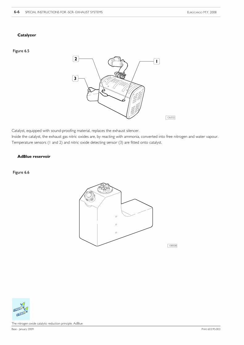
6-6 SPECIAL INSTRUCTIONS FOR -SCR- EXHAUST SYSTEMS EUROCARGO M.Y. 2008
Base - January 2009 Print 603.95.003
The nitrogen oxide catalytic reduction principle. AdBlue
Catalyzer
Figure 6.5
126332
Catalyst, equipped with sound-proofing material, replaces the exhaust silencer.
Inside the catalyst, the exhaust gas nitric oxides are, by reacting with ammonia, converted into free nitrogen and water vapour.
Temperature sensors (1 and 2) and nitric oxide detecting sensor (3) are fitted onto catalyst.
AdBlue reservoir
Figure 6.6
108508
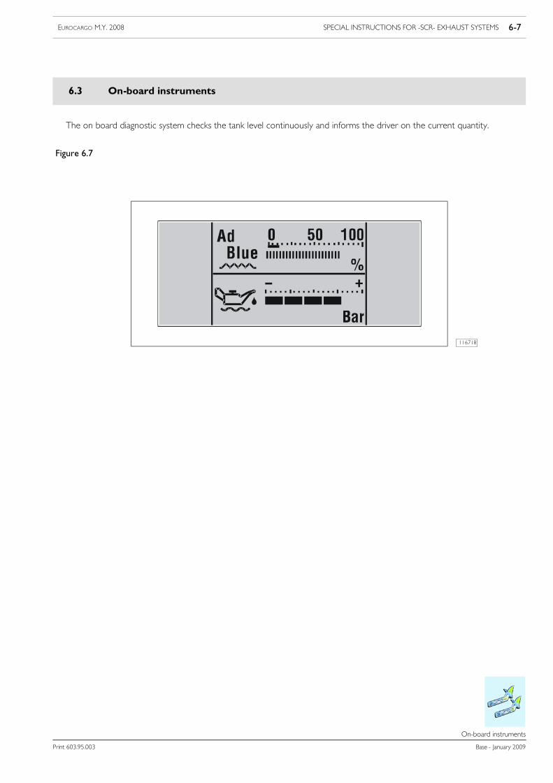
SPECIAL INSTRUCTIONS FOR -SCR- EXHAUST SYSTEMS 6-7EUROCARGO M.Y. 2008
Print 603.95.003 Base - January 2009
On-board instruments
On---board instruments
6.3 On-board instruments
The on board diagnostic system checks the tank level continuously and informs the driver on the current quantity.
Figure 6.7
116718
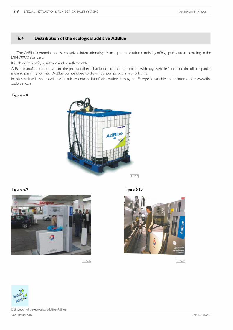
6-8 SPECIAL INSTRUCTIONS FOR -SCR- EXHAUST SYSTEMS EUROCARGO M.Y. 2008
Base - January 2009 Print 603.95.003
Distribution of the ecological additive AdBlue
Distribution of the ecological additive AdBlue
6.4 Distribution of the ecological additive AdBlue
The ’AdBlue’ denomination is recognized internationally; it is an aqueous solution consisting of high purity urea according to theDIN 70070 standard.
It is absolutely safe, non-toxic and non-flammable.
AdBlue manufacturers can assure the product direct distribution to the transporters with huge vehicle fleets, and the oil companiesare also planning to install AdBlue pumps close to diesel fuel pumps within a short time.
In this case it will also be available in tanks. A detailed list of sales outlets throughout Europe is available on the internet site: www.fin-dadblue. com
Figure 6.8
114735
Figure 6.9 Figure 6.10
114737114736

SPECIAL INSTRUCTIONS FOR -SCR- EXHAUST SYSTEMS 6-9EUROCARGO M.Y. 2008
Print 603.95.003 Base - January 2009
Specifications for installation and removal
Specifications for installation and removal
6.5 Specifications for installation and removal
The instructions that follow are intended for the AdBlue injection system of the Bosch DENOX2 type, within the SCR system.
If Bodybuilders make changes to the frame, the following procedures must be followed under all circumstances:
- disassembly: disconnect the hydraulic connectors first and then the electric connectors;
- assembly: connect the electric connectors first and then the hydraulic connectors.
Compliance with this assembly/disassembly procedure will ensure that AdBlue does not come into contact with the electricconnectors.
6.5.1 Operations for positioning the AdBlue tank
As regards the AdBlue tank, ensure that:
- the tank ventilation pipe is never closed;
- the reservoir must contain at least 5 l of AdBlue at the end of each operation to ensure the dosing module is cooled;
- after each operation, the tank does not contain more than 85% of AdBlue (corresponding to the max reading of the level sensor)with respect to the tank total volume, so as to guarantee enough room for AdBlue to expand during freezing at temperaturesbelow -11 °C;
- when fitting equipment onto the chassis, there is enough room for the AdBlue fill gun (1, Figure 6.11) to fit completely andcorrectly into the tank filler.
If specific-shaped tanks are available, these must be made out of polyethylene or stainless steel 1.4301, 1.43, in each case the tankheight must be respected.
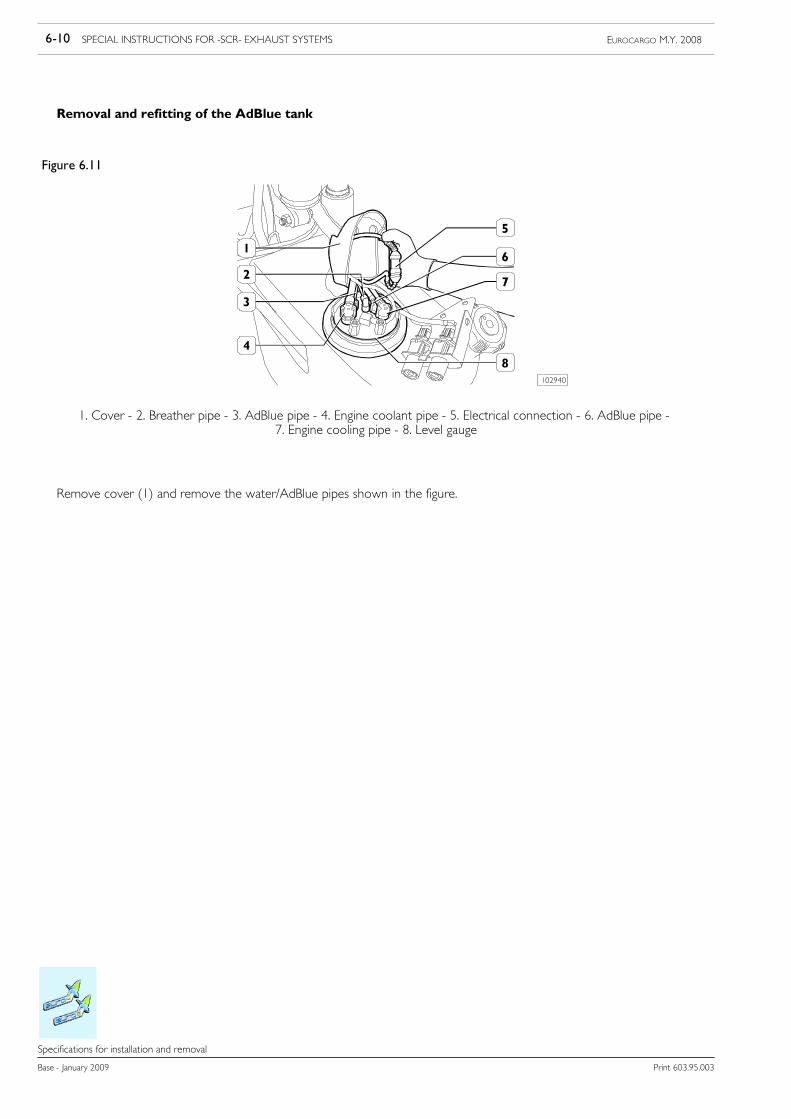
6-10 SPECIAL INSTRUCTIONS FOR -SCR- EXHAUST SYSTEMS EUROCARGO M.Y. 2008
Base - January 2009 Print 603.95.003
Specifications for installation and removal
Removal and refitting of the AdBlue tank
Figure 6.11
102940
1. Cover - 2. Breather pipe - 3. AdBlue pipe - 4. Engine coolant pipe - 5. Electrical connection - 6. AdBlue pipe -7. Engine cooling pipe - 8. Level gauge
Remove cover (1) and remove the water/AdBlue pipes shown in the figure.
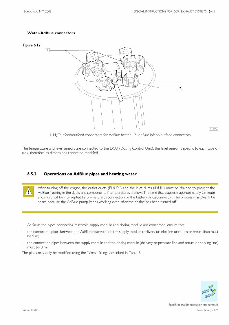
SPECIAL INSTRUCTIONS FOR -SCR- EXHAUST SYSTEMS 6-11EUROCARGO M.Y. 2008
Print 603.95.003 Base - January 2009
Specifications for installation and removal
Water/AdBlue connectors
Figure 6.12
114742
1. H2O infeed/outfeed connectors for AdBlue heater - 2. AdBlue infeed/outfeed connectors
The temperature and level sensors are connected to the DCU (Dosing Control Unit); the level sensor is specific to each type oftank, therefore its dimensions cannot be modified.
6.5.2 Operations on AdBlue pipes and heating water
After turning off the engine, the outlet ducts (PL/UPL) and the inlet ducts (IL/UIL) must be drained to prevent theAdBlue freezing in the ducts and components if temperatures are low. The time that elapses is approximately 2 minuteand must not be interrupted by premature disconnection or the battery or disconnector. The process may clearly beheard because the AdBlue pump keeps working even after the engine has been turned off.
!
As far as the pipes connecting reservoir, supply module and dosing module are concerned, ensure that:
- the connection pipes between the AdBlue reservoir and the supply module (delivery or inlet line or return or return line) mustbe 5 m;
- the connection pipes between the supply module and the dosing module (delivery or pressure line and return or cooling line)must be 3 m.
The pipes may only be modified using the ”Voss” fittings described in Table 6.1.
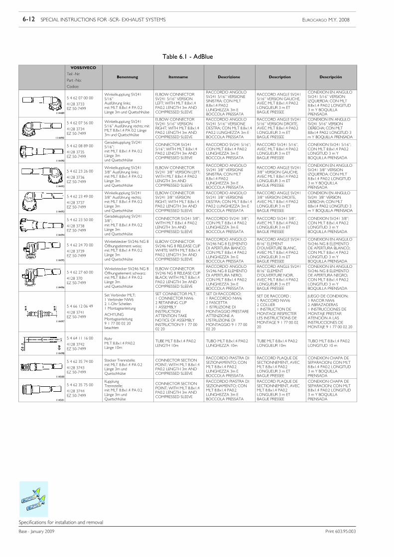
6-12 SPECIAL INSTRUCTIONS FOR -SCR- EXHAUST SYSTEMS EUROCARGO M.Y. 2008
Base - January 2009 Print 603.95.003
Specifications for installation and removal
Table 6.1 - AdBlue
VOSS/IVECO
Teil -Nr:
Part -No:
Codice:
Benennung Itemname Descrizione Description Descripción
114489
5 4 62 07 00 00
4128 3733EZ 50-7499
Winkelkupplung SV2415/16”Ausführung links;mit MLT 8.8x1.4 PA 0.2Länge 3m und Quetschhülse
ELBOW CONNECTORSV241 5/16” VERSIONLEFT; WITH MLT 8.8x1.4PA0.2 LENGTH 3m ANDCOMPRESSED SLEEVE
RACCORDO ANGOLOSV241 5/16” VERSIONESINISTRA; CON MLT8.8x1.4 PA0.2LUNGHEZZA 3m EBOCCOLA PRESSATA
RACCORD ANGLE SV2415/16” VERSION GAUCHE,AVEC MLT 8.8x1.4 PA0.2LONGUEUR 3 m ETBAGUE PRESSEE
CONEXION EN ANGULOSV241 5/16” VERSIONIZQUIERDA; CON MLT8.8x1.4 PA0.2 LONGITUD3 m Y BOQUILLAPRENSADA
114490
5 4 62 07 56 00
4128 3734EZ 50-7499
Winkelkupplung SV2415/16” Ausführung rechts; mitMLT 8.8x1.4 PA 0.2 Länge3m und Quetschhülse
ELBOW CONNECTORSV241 5/16” VERSIONRIGHT; WITH MLT 8.8x1.4PA0.2 LENGTH 3m ANDCOMPRESSED SLEEVE
RACCORDO ANGOLOSV241 5/16” VERSIONEDESTRA; CON MLT 8.8x1.4PA0.2 LUNGHEZZA 3m EBOCCOLA PRESSATA
RACCORD ANGLE SV2415/16” VERSION DROITE,AVEC MLT 8.8x1.4 PA0.2LONGUEUR 3 m ETBAGUE PRESSEE
CONEXION EN ANGULOSV241 5/16” VERSIONDERECHA; CON MLT8.8x1.4 PA0.2 LONGITUD 3m Y BOQUILLA PRENSADA
114490
5 4 62 08 89 00
4128 3735EZ 50-7499
Geradekupplung SV2415/16”;mit MLT 8.8x1.4 PA 0.2Länge 3mund Quetschhülse
CONNECTOR SV2415/16”; WITH MLT 8.8x1.4PA0.2 LENGTH 3m ANDCOMPRESSED SLEEVE
RACCORDO SV241 5/16”;CON MLT 8.8x1.4 PA0.2LUNGHEZZA 3m EBOCCOLA PRESSATA
RACCORD SV241 5/16”,AVEC MLT 8.8x1.4 PA0.2LONGUEUR 3 m ETBAGUE PRESSEE
CONEXION SV241 5/16”;CON MLT 8.8x1.4 PA0.2LONGITUD 3 m YBOQUILLA PRENSADA
114492
5 4 62 23 26 00
4128 3736EZ 50-7499
Winkelkupplung SV2413/8” Ausführung links;mit MLT 8.8x1.4 PA 0.2Länge 3mund Quetschhülse
ELBOW CONNECTORSV241 3/8” VERSION LEFT;WITH MLT 8.8x1.4 PA0.2LENGTH 3m ANDCOMPRESSED SLEEVE
RACCORDO ANGOLOSV241 3/8” VERSIONESINISTRA; CON MLT8.8x1.4 PA0.2LUNGHEZZA 3m EBOCCOLA PRESSATA
RACCORD ANGLE SV2413/8” VERSION GAUCHE,AVEC MLT 8.8x1.4 PA0.2LONGUEUR 3 m ETBAGUE PRESSEE
CONEXION EN ANGULOSV241 3/8” VERSIONIZQUIERDA; CON MLT8.8x1.4 PA0.2 LONGITUD3 m Y BOQUILLAPRENSADA
114493
5 4 62 23 49 00
4128 3737EZ 50-7499
Winkelkupplung SV2413/8” Ausführung rechts;mit MLT 8.8x1.4 PA 0.2Länge 3mund Quetschhülse
ELBOW CONNECTORSV241 3/8” VERSIONRIGHT; WITH MLT 8.8x1.4PA0.2 LENGTH 3m ANDCOMPRESSED SLEEVE
RACCORDO ANGOLOSV241 3/8” VERSIONEDESTRA; CON MLT 8.8x1.4PA0.2 LUNGHEZZA 3m EBOCCOLA PRESSATA
RACCORD ANGLE SV2413/8” VERSION DROITE,AVEC MLT 8.8x1.4 PA0.2LONGUEUR 3 m ETBAGUE PRESSEE
CONEXION EN ANGULOSV241 3/8” VERSIONDERECHA; CON MLT8.8x1.4 PA0.2 LONGITUD 3m Y BOQUILLA PRENSADA
114494
5 4 62 23 50 00
4128 3738EZ 50-7499
Geradekupplung SV2413/8”;mit MLT 8.8x1.4 PA 0.2Länge 3mund Quetschhülse
CONNECTOR SV241 3/8”;WITH MLT 8.8x1.4 PA0.2LENGTH 3m ANDCOMPRESSED SLEEVE
RACCORDO SV241 3/8”;CON MLT 8.8x1.4 PA0.2LUNGHEZZA 3m EBOCCOLA PRESSATA
RACCORD SV241 3/8”,AVEC MLT 8.8x1.4 PA0.2LONGUEUR 3 m ETBAGUE PRESSEE
CONEXION SV241 3/8”;CON MLT 8.8x1.4 PA0.2LONGITUD 3 m YBOQUILLA PRENSADA
114495
5 4 62 24 70 00
4128 3739EZ 50-7499
Winkelstecker SV246 NG 8Öffnungselement weiss;mit MLT 8.8x1.4 PA 0.2Länge 3mund Quetschhülse
ELBOW CONNECTORSV246 NG 8 RELEASE CLIPWHITE; WITH MLT 8.8x1.4PA0.2 LENGTH 3m ANDCOMPRESSED SLEEVE
RACCORDO ANGOLOSV246 NG 8 ELEMENTODI APERTURA BIANCO;CON MLT 8.8x1.4 PA0.2LUNGHEZZA 3m EBOCCOLA PRESSATA
RACCORD ANGLE SV2418/16” ELEMENTD’OUVERTURE BLANC,AVEC MLT 8.8x1.4 PA0.2LONGUEUR 3 m ETBAGUE PRESSEE
CONEXION EN ANGULOSV246 NG 8 ELEMENTODE APERTURA BLANCO;CON MLT 8.8x1.4 PA0.2LONGITUD 3 m YBOQUILLA PRENSADA
114496
5 4 62 27 60 00
4128 370EZ 50-7499
Winkelstecker SV246 NG 8Öffnungselement schwarz;mit MLT 8.8x1.4 PA 0.2Länge 3mund Quetschhülse
ELBOW CONNECTORSV246 NG 8 RELEASE CLIPBLACK; WITH MLT 8.8x1.4PA0.2 LENGTH 3m ANDCOMPRESSED SLEEVE
RACCORDO ANGOLOSV246 NG 8 ELEMENTODI APERTURA NERO;CON MLT 8.8x1.4 PA0.2LUNGHEZZA 3m EBOCCOLA PRESSATA
RACCORD ANGLE SV2418/16” ELEMENTD’OUVERTURE NOIR,AVEC MLT 8.8x1.4 PA0.2LONGUEUR 3 m ETBAGUE PRESSEE
CONEXION EN ANGULOSV246 NG 8 ELEMENTODE APERTURA NEGRO;CON MLT 8.8x1.4 PA0.2LONGITUD 3 m YBOQUILLA PRENSADA
114497
5 4 66 12 06 49
4128 3741EZ 50-7499
Set Verbinder MLT;1 Verbinder NW62 1-Ohr Schellen1 Montageanleitung
ACHTUNGMontageanleitung9 1 77 00 02 20beachten
SET CONNECTOR MLT;1 CONNECTOR NW62 RETAINING CLIP1 ASSEMBLYINSTRUCTIONATTENTION TAKENOTICE OF ASSEMBLYINSTRUCTION 9 1 77 0002 20
SET DI RACCORDO;1 RACCORDO NW62 FASCETTA1 ISTRUZIONE DIMONTAGGIO PRESTAREATTENZIONE AL’ISTRUZIONE DIMONTAGGIO 9 1 77 0002 20
SET DE RACCORD ;1 RACCORD NVV62 COLLIER1 INSTRUCTION DEMONTAGE RESPECTERLES INSTRUCTIONS DEMONTAGE 9 1 77 00 0220
JUEGO DE CONEXION;1 RACOR NW62 ABRAZADERAS1 INSTRUCCIONES DEMONTAJE PRESTARATENCION A LASINSTRUCCIONES DEMONTAJE 9 1 77 00 02 20
114498
5 4 64 11 16 00
4128 3742EZ 50-7499
RohrMLT 8.8x1.4 PA0.2Länge 10m
TUBE MLT 8.8x1.4 PA0.2LENGTH 10m
TUBO MLT 8.8x1.4 PA0.2LUNGHEZZA 10m
TUBE MLT 8.8x1.4 PA0.2LONGUEUR 10m
TUBO MLT 8.8x1.4 PA0.2LONGITUD 10 m
114500
5 4 62 35 74 00
4128 3743EZ 50-7499
Stecker Trennstelle;mit MLT 8.8x1.4 PA 0.2Länge 3m undQuetschhülse
CONNECTOR SECTIONPOINT; WITH MLT 8.8x1.4PA0.2 LENGTH 3m ANDCOMPRESSED SLEEVE
RACCORDO PIASTRA DISEZIONAMENTO; CONMLT 8.8x1.4 PA0.2LUNGHEZZA 3m EBOCCOLA PRESSATA
RACCORD PLAQUE DESECTIONNEMENT, AVECMLT 8.8x1.4 PA0.2LONGUEUR 3 m ETBAGUE PRESSEE
CONEXION CHAPA DESEPARACION; CON MLT8.8x1.4 PA0.2 LONGITUD3 m Y BOQUILLAPRENSADA
114501
5 4 62 35 75 00
4128 3744EZ 50-7499
KupplungTrennstelle;mit MLT 8.8x1.4 PA 0.2Länge 3m undQuetschhülse
CONNECTOR SECTIONPOINT; WITH MLT 8.8x1.4PA0.2 LENGTH 3m ANDCOMPRESSED SLEEVE
RACCORDO PIASTRA DISEZIONAMENTO; CONMLT 8.8x1.4 PA0.2LUNGHEZZA 3m EBOCCOLA PRESSATA
RACCORD PLAQUE DESECTIONNEMENT, AVECMLT 8.8x1.4 PA0.2LONGUEUR 3 m ETBAGUE PRESSEE
CONEXION CHAPA DESEPARACION; CON MLT8.8x1.4 PA0.2 LONGITUD3 m Y BOQUILLAPRENSADA
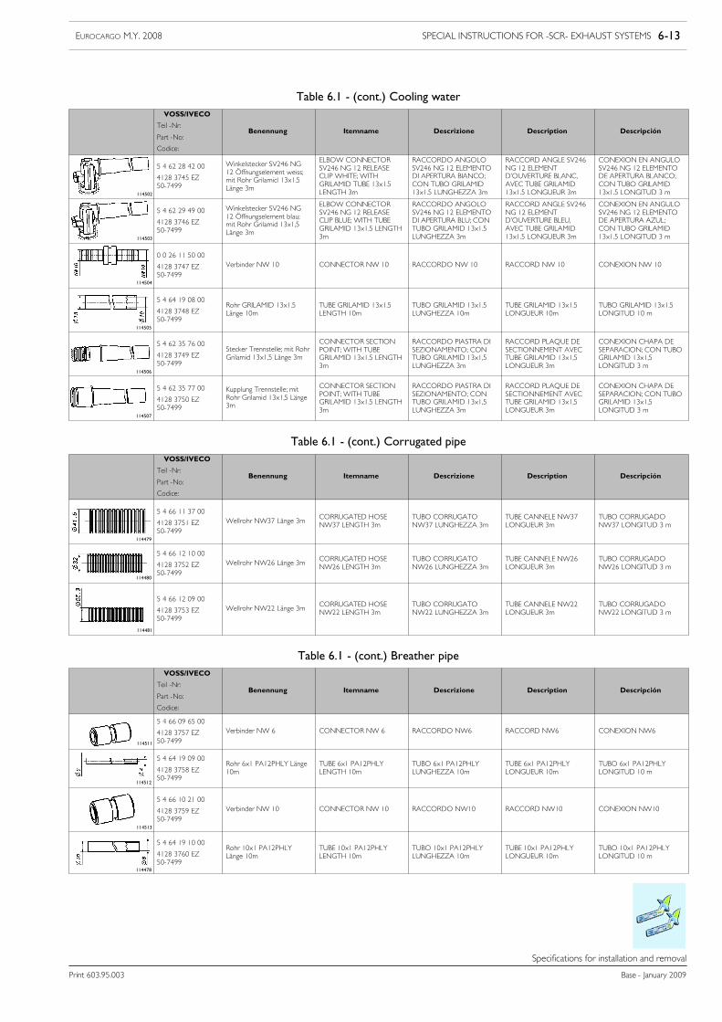
SPECIAL INSTRUCTIONS FOR -SCR- EXHAUST SYSTEMS 6-13EUROCARGO M.Y. 2008
Print 603.95.003 Base - January 2009
Specifications for installation and removal
Table 6.1 - (cont.) Cooling waterVOSS/IVECO
Teil -Nr:
Part -No:
Codice:
Benennung Itemname Descrizione Description Descripción
114502
5 4 62 28 42 00
4128 3745 EZ50-7499
Winkelstecker SV246 NG12 Öffnungselement weiss;mit Rohr Grilamicl 13x1.5Länge 3m
ELBOW CONNECTORSV246 NG 12 RELEASECLIP WHITE; WITHGRILAMID TUBE 13x1.5LENGTH 3m
RACCORDO ANGOLOSV246 NG 12 ELEMENTODI APERTURA BIANCO;CON TUBO GRILAMID13x1.5 LUNGHEZZA 3m
RACCORD ANGLE SV246NG 12 ELEMENTD’OUVERTURE BLANC,AVEC TUBE GRILAMID13x1.5 LONGUEUR 3m
CONEXION EN ANGULOSV246 NG 12 ELEMENTODE APERTURA BLANCO;CON TUBO GRILAMID13x1.5 LONGITUD 3 m
114503
5 4 62 29 49 00
4128 3746 EZ50-7499
Winkelstecker SV246 NG12 Öffnungselement blau;mit Rohr Grilamid 13x1,5Länge 3m
ELBOW CONNECTORSV246 NG 12 RELEASECLIP BLUE; WITH TUBEGRILAMID 13x1.5 LENGTH3m
RACCORDO ANGOLOSV246 NG 12 ELEMENTODI APERTURA BLU; CONTUBO GRILAMID 13x1.5LUNGHEZZA 3m
RACCORD ANGLE SV246NG 12 ELEMENTD’OUVERTURE BLEU,AVEC TUBE GRILAMID13x1.5 LONGUEUR 3m
CONEXION EN ANGULOSV246 NG 12 ELEMENTODE APERTURA AZUL;CON TUBO GRILAMID13x1.5 LONGITUD 3 m
114504
0 0 26 11 50 00
4128 3747 EZ50-7499
Verbinder NW 10 CONNECTOR NW 10 RACCORDO NW 10 RACCORD NW 10 CONEXION NW 10
114505
5 4 64 19 08 00
4128 3748 EZ50-7499
Rohr GRILAMID 13x1.5Länge 10m
TUBE GRILAMID 13x1.5LENGTH 10m
TUBO GRILAMID 13x1.5LUNGHEZZA 10m
TUBE GRILAMID 13x1.5LONGUEUR 10m
TUBO GRILAMID 13x1.5LONGITUD 10 m
114506
5 4 62 35 76 00
4128 3749 EZ50-7499
Stecker Trennstelle; mit RohrGrilamid 13x1,5 Länge 3m
CONNECTOR SECTIONPOINT; WITH TUBEGRILAMID 13x1.5 LENGTH3m
RACCORDO PIASTRA DISEZIONAMENTO; CONTUBO GRILAMID 13x1,5LUNGHEZZA 3m
RACCORD PLAQUE DESECTIONNEMENT AVECTUBE GRILAMID 13x1,5LONGUEUR 3m
CONEXION CHAPA DESEPARACION; CON TUBOGRILAMID 13x1,5LONGITUD 3 m
114507
5 4 62 35 77 00
4128 3750 EZ50-7499
Kupplung Trennstelle; mitRohr Grilamid 13x1,5 Länge3m
CONNECTOR SECTIONPOINT; WITH TUBEGRILAMID 13x1.5 LENGTH3m
RACCORDO PIASTRA DISEZIONAMENTO; CONTUBO GRILAMID 13x1,5LUNGHEZZA 3m
RACCORD PLAQUE DESECTIONNEMENT AVECTUBE GRILAMID 13x1,5LONGUEUR 3m
CONEXION CHAPA DESEPARACION; CON TUBOGRILAMID 13x1,5LONGITUD 3 m
Table 6.1 - (cont.) Corrugated pipeVOSS/IVECO
Teil -Nr:
Part -No:
Codice:
Benennung Itemname Descrizione Description Descripción
114479
5 4 66 11 37 00
4128 3751 EZ50-7499
Wellrohr NW37 Länge 3m CORRUGATED HOSENW37 LENGTH 3m
TUBO CORRUGATONW37 LUNGHEZZA 3m
TUBE CANNELE NW37LONGUEUR 3m
TUBO CORRUGADONW37 LONGITUD 3 m
114480
5 4 66 12 10 00
4128 3752 EZ50-7499
Wellrohr NW26 Länge 3m CORRUGATED HOSENW26 LENGTH 3m
TUBO CORRUGATONW26 LUNGHEZZA 3m
TUBE CANNELE NW26LONGUEUR 3m
TUBO CORRUGADONW26 LONGITUD 3 m
114481
5 4 66 12 09 00
4128 3753 EZ50-7499
Wellrohr NW22 Länge 3m CORRUGATED HOSENW22 LENGTH 3m
TUBO CORRUGATONW22 LUNGHEZZA 3m
TUBE CANNELE NW22LONGUEUR 3m
TUBO CORRUGADONW22 LONGITUD 3 m
Table 6.1 - (cont.) Breather pipeVOSS/IVECO
Teil -Nr:
Part -No:
Codice:
Benennung Itemname Descrizione Description Descripción
114511
5 4 66 09 65 00
4128 3757 EZ50-7499
Verbinder NW 6 CONNECTOR NW 6 RACCORDO NW6 RACCORD NW6 CONEXION NW6
114512
5 4 64 19 09 00
4128 3758 EZ50-7499
Rohr 6x1 PA12PHLY Länge10m
TUBE 6x1 PA12PHLYLENGTH 10m
TUBO 6x1 PA12PHLYLUNGHEZZA 10m
TUBE 6x1 PA12PHLYLONGUEUR 10m
TUBO 6x1 PA12PHLYLONGITUD 10 m
114513
5 4 66 10 21 00
4128 3759 EZ50-7499
Verbinder NW 10 CONNECTOR NW 10 RACCORDO NW10 RACCORD NW10 CONEXION NW10
114478
5 4 64 19 10 00
4128 3760 EZ50-7499
Rohr 10x1 PA12PHLYLänge 10m
TUBE 10x1 PA12PHLYLENGTH 10m
TUBO 10x1 PA12PHLYLUNGHEZZA 10m
TUBE 10x1 PA12PHLYLONGUEUR 10m
TUBO 10x1 PA12PHLYLONGITUD 10 m
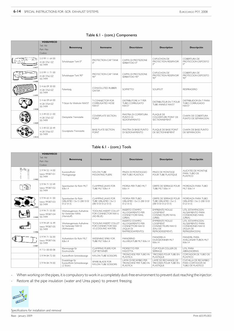
6-14 SPECIAL INSTRUCTIONS FOR -SCR- EXHAUST SYSTEMS EUROCARGO M.Y. 2008
Base - January 2009 Print 603.95.003
Specifications for installation and removal
Table 6.1 - (cont.) Components
VOSS/IVECO
Teil -Nr:
Part -No:
Codice:
Benennung Itemname Descrizione Description Descripción
114477
5 0 99 11 64 00
4128 3761 EZ50-7499
Schutzkappe Tank 0° PROTECTION CAP TANK0°
CAPPA DI PROTEZIONESERBATOIO 0°
CAPUCHON DEPROTECTION RESERVOIR0°
COBERTURA DEPROTECCION DEPOSITO0°
114488
5 0 99 11 71 00
4128 3762 EZ50-7499
Schutzkappe Tank 90° PROTECTION CAP TANK90°
CAPPA DI PROTEZIONESERBATOIO 90°
CAPUCHON DEPROTECTION RESERVOIR90°
COBERTURA DEPROTECCION DEPOSITO90°
114499
5 4 66 09 30 00
4128 3763 EZ50-7499
Faltenbalg CONVOLUTED RUBBERGAITER SOFFIETTO SOUFFLET RESPIRADERO
114508
5 4 66 09 64 00
4128 3764 EZ50-7499
T-Stück für Wellrohr NW37T-CONNECTOR FORCORRUGATED HOSENW37
DISTRIBUTORE A T PERTUBO CORRUGATONW37
DISTRIBUTEUR EN T POURTUBE ANNELE NW37
DISTRIBUIDOR EN T PARATUBO CORRUGADONW37
114509
5 3 49 03 21 00
4128 3765 EZ50-7499
Deckplatte Trennstelle COVERPLATE SECTIONPOINT
PIASTRA DI COPERTURAPUNTO DISEZIONAMENTO
PLAQUE DECOUVERTURE POINT DESECTIONNEMENT
CHAPA DE COBERTURAPUNTO DE SEPARACION
114510
5 3 49 03 20 49
4128 3766 EZ50-7499
Grundplatte Trennstelle BASE PLATE SECTIONPOINT
PIASTRA DI BASE PUNTODI SEZIONAMENTO
PLAQUE DE BASE POINTDE SECTIONNEMENT
CHAPA DE BASE PUNTODE SEPARACION
Table 6.1 - (cont.) Tools
VOSS/IVECO
Teil -Nr:
Part -No:
Codice:
Benennung Itemname Descrizione Description Descripción
114482
5 9 94 52 14 00
Iveco: 9938710150-7499
KunststoffrohrMontagezange
NYLON TUBEMOUNTING PLIERS
PINZA DI MONTAGGIOPER TUBO PLASTICA
PINCE DE MONTAGEPOUR TUBE PLASTIQUE
ALICATES DE MONTAJEPARA TUBO DEPLASTICO
5 9 94 71 53 49
Iveco: 9938710250-7499
Spannbacken für Rohr MLT8.8x1.4
CLAMPING JAWS FORTUBE MLT 8.8x1.4
MORSA PER TUBO MLT8.8x1.4
GRIFFE DE SERRAGE POURTUBE MLT 8.8x1.4
MORDAZA PARA TUBOMLT 8.8x1.4
114484
5 9 94 65 41 00
Iveco: 9938710350-7499
Spannbacken für RohrGRILAMID 13x1.5 (08/ 010/012/ 013)
CLAMPING JAWS FORTUBE GRILAMID 13x1.5(08/ 010/ 012/ 013)
MORSA PER TUBOGRILAMID 13x1.5 (08/ 010/012/ 013)
GRIFFE DE SERRAGE POURTUBE GRILAMID 13x1.5(08/ 010/ 012/ 013)
MORDAZA PARA TUBOGRILAMID 13x1.5 (08/ 010/012/ 013)
114485
5 9 94 71 55 00
Iveco: 9938710450-7499
Werkzeugeinsatz Aufnahmefür Verbinder NW6(Harnstoff)
TOOLING INSERT COLLETFOR CONNECTOR NW 6(AD-BLUE)
INSERTO STAMPOALLOGIAMENTO PERCONNETTORI NW6(UREA)
EMPREINTE MOULELOGEMENTCONNECTEURS NVV6(UREE)
UTIL ESTAMPACIONALOJAMIENTO PARACONEXIONES NW6(UREA)
114486
5 9 94 69 16 49
Iveco: 9938710550-7499
Werkzeugeinsatz Aufnahmefür Verbinder NW10(Kühlwasser)
TOOLING INSERT COLLETFOR CONNECTOR NW10 (COOLING WATER)
INSERTO STAMPOALLOGIAMENTO PERCONNETTORI NW10(AQUA DIRAFFREDDAMENTO)
EMPREINTE MOULELOGEMENTCONNECTEURS NW10(EAU DEREFROIDISSEMENT)
UTIL ESTAMPACIONALOJAMIENTO PARACONEXIONES NW10(AGUA DEREFRIGERACION)
114487
5 9 94 71 56 00
Iveco: 9938710650-7499
Aufweitdorn für Rohr MLT8.8x1.4
WIDENING SPIKE FORTUBE MLT 8.8x1.4
MANDRINOALLARGATUBI MLT 8.8x1.4
MANDRIN ADUDGEONNER MLT8.8x1.4
MANDRIL PARAAVELLANAR TUBOS MLT8.8x1.4
9 7 51 00 00 08 Klemmzange fürEinohrschelle
CLAMPING PLIERS FORCLIP RETAINER
MORSETTO PERFASCETTA
CLIP POUR COLLIER DESERRAGE
UTIL PARAABRAZADERAS
5 9 94 84 72 00 Kunstoffrohr-Schneidezange NYLON TUBE SCISSORS TRONCHESE PER TUBO INPLASTICA
TRICOISES POUR TUBE ENPLASTIQUE
CORTADOR DE TUBO DEPLASTICO
5 9 94 84 74 00Ersatzklinge fürKunstoffrohr-Schneidezange(2 Stück)
SPARE BLADE FORNYLON TUBE SCISSORS
LAMA DI RICAMBIO PERTRONCHESE PER TUBO INPLASTICA
LAME DE RECHANGE DETRICOISES POUR TUBE ENPLASTIQUE
CUCHILLA DE RECAMBIOPARA CORTADOR DETUBO DE PLASTICO
- Whenworking on the pipes, it is compulsory towork in a completely dust-free environment to prevent dust reaching the injector.
- Restore all the pipe insulation (water and Urea pipes) to prevent freezing.
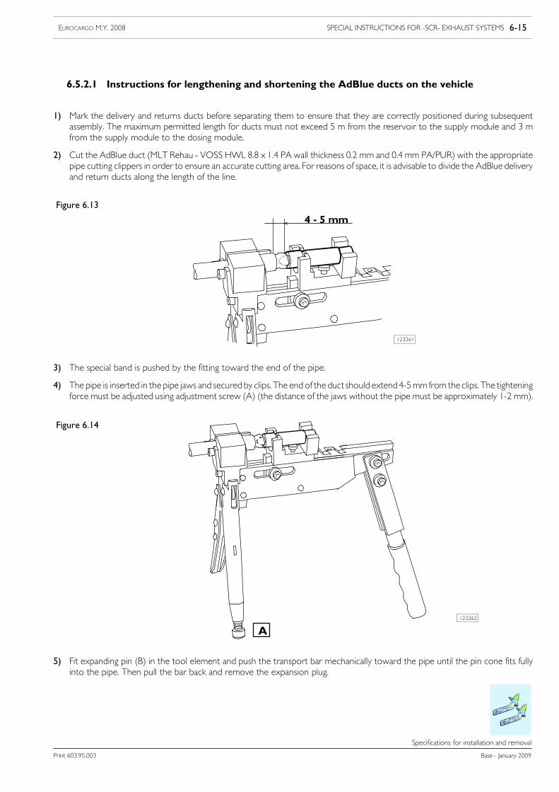
SPECIAL INSTRUCTIONS FOR -SCR- EXHAUST SYSTEMS 6-15EUROCARGO M.Y. 2008
Print 603.95.003 Base - January 2009
Specifications for installation and removal
6.5.2.1 Instructions for lengthening and shortening the AdBlue ducts on the vehicle
1) Mark the delivery and returns ducts before separating them to ensure that they are correctly positioned during subsequentassembly. The maximum permitted length for ducts must not exceed 5 m from the reservoir to the supply module and 3 mfrom the supply module to the dosing module.
2) Cut the AdBlue duct (MLT Rehau - VOSS HWL 8.8 x 1.4 PA wall thickness 0.2 mm and 0.4 mm PA/PUR) with the appropriatepipe cutting clippers in order to ensure an accurate cutting area. For reasons of space, it is advisable to divide the AdBlue deliveryand return ducts along the length of the line.
Figure 6.13
123261
3) The special band is pushed by the fitting toward the end of the pipe.
4) The pipe is inserted in the pipe jaws and secured by clips. The end of the duct should extend4-5mmfrom the clips. The tighteningforce must be adjusted using adjustment screw (A) (the distance of the jaws without the pipe must be approximately 1-2 mm).
Figure 6.14
123262
A
5) Fit expanding pin (B) in the tool element and push the transport bar mechanically toward the pipe until the pin cone fits fullyinto the pipe. Then pull the bar back and remove the expansion plug.
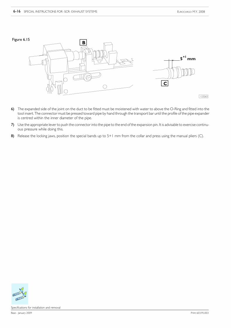
6-16 SPECIAL INSTRUCTIONS FOR -SCR- EXHAUST SYSTEMS EUROCARGO M.Y. 2008
Base - January 2009 Print 603.95.003
Specifications for installation and removal
Figure 6.15
123263
B
C
6) The expanded side of the joint on the duct to be fitted must be moistened with water to above the O-Ring and fitted into thetool insert. The connector must be pressed toward pipe by hand through the transport bar until the profile of the pipe expanderis centred within the inner diameter of the pipe.
7) Use the appropriate lever to push the connector into the pipe to the end of the expansion pin. It is advisable to exercise continu-ous pressure while doing this.
8) Release the locking jaws, position the special bands up to 5+1 mm from the collar and press using the manual pliers (C).
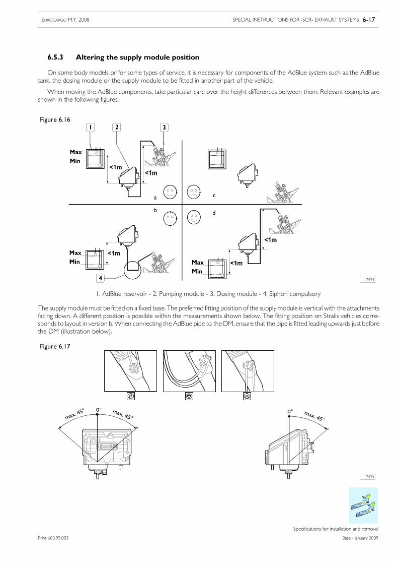
SPECIAL INSTRUCTIONS FOR -SCR- EXHAUST SYSTEMS 6-17EUROCARGO M.Y. 2008
Print 603.95.003 Base - January 2009
Specifications for installation and removal
6.5.3 Altering the supply module position
On some body models or for some types of service, it is necessary for components of the AdBlue system such as the AdBluetank, the dosing module or the supply module to be fitted in another part of the vehicle.
When moving the AdBlue components, take particular care over the height differences between them. Relevant examples areshown in the following figures.
Figure 6.16
117474
1. AdBlue reservoir - 2. Pumping module - 3. Dosing module - 4. Siphon compulsory
The supply module must be fitted on a fixed base. The preferred fitting position of the supply module is vertical with the attachmentsfacing down. A different position is possible within the measurements shown below. The fitting position on Stralis vehicles corre-sponds to layout in version b.When connecting the AdBlue pipe to the DM, ensure that the pipe is fitted leading upwards just beforethe DM (illustration below).
Figure 6.17
117474
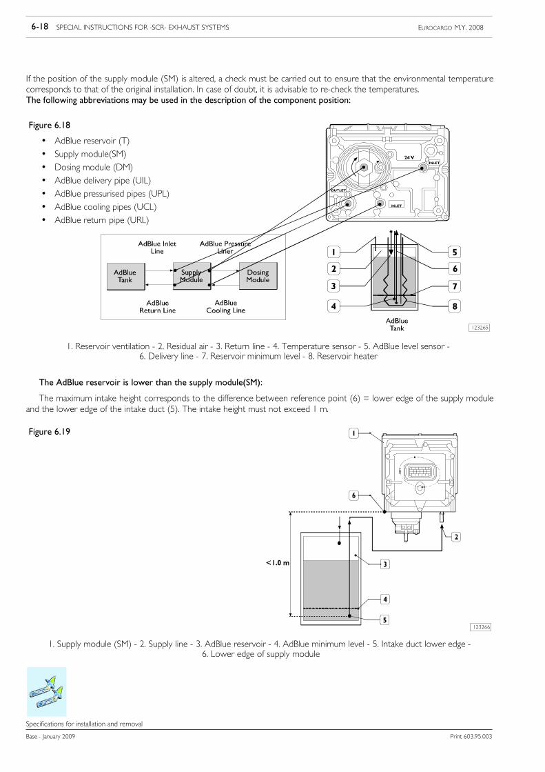
6-18 SPECIAL INSTRUCTIONS FOR -SCR- EXHAUST SYSTEMS EUROCARGO M.Y. 2008
Base - January 2009 Print 603.95.003
Specifications for installation and removal
If the position of the supply module (SM) is altered, a check must be carried out to ensure that the environmental temperaturecorresponds to that of the original installation. In case of doubt, it is advisable to re-check the temperatures.The following abbreviations may be used in the description of the component position:
Figure 6.18
• AdBlue reservoir (T)
• Supply module(SM)
• Dosing module (DM)
• AdBlue delivery pipe (UIL)
• AdBlue pressurised pipes (UPL)
• AdBlue cooling pipes (UCL)
• AdBlue return pipe (URL)
123265
1. Reservoir ventilation - 2. Residual air - 3. Return line - 4. Temperature sensor - 5. AdBlue level sensor -6. Delivery line - 7. Reservoir minimum level - 8. Reservoir heater
The AdBlue reservoir is lower than the supply module(SM):
The maximum intake height corresponds to the difference between reference point (6) = lower edge of the supply moduleand the lower edge of the intake duct (5). The intake height must not exceed 1 m.
Figure 6.19
123266
1. Supply module (SM) - 2. Supply line - 3. AdBlue reservoir - 4. AdBlue minimum level - 5. Intake duct lower edge -6. Lower edge of supply module
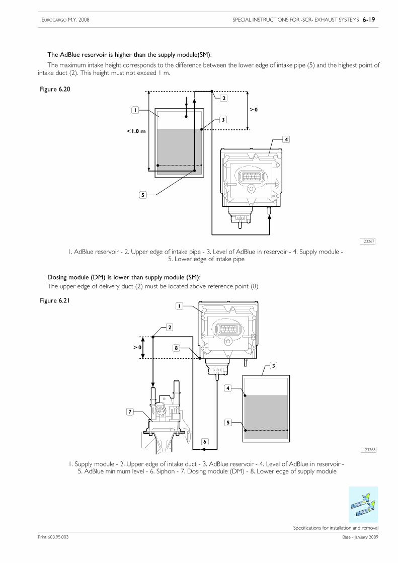
SPECIAL INSTRUCTIONS FOR -SCR- EXHAUST SYSTEMS 6-19EUROCARGO M.Y. 2008
Print 603.95.003 Base - January 2009
Specifications for installation and removal
The AdBlue reservoir is higher than the supply module(SM):
The maximum intake height corresponds to the difference between the lower edge of intake pipe (5) and the highest point ofintake duct (2). This height must not exceed 1 m.
Figure 6.20
123267
1. AdBlue reservoir - 2. Upper edge of intake pipe - 3. Level of AdBlue in reservoir - 4. Supply module -5. Lower edge of intake pipe
Dosing module (DM) is lower than supply module (SM):The upper edge of delivery duct (2) must be located above reference point (8).
123268
1. Supply module - 2. Upper edge of intake duct - 3. AdBlue reservoir - 4. Level of AdBlue in reservoir -5. AdBlue minimum level - 6. Siphon - 7. Dosing module (DM) - 8. Lower edge of supply module
Figure 6.21
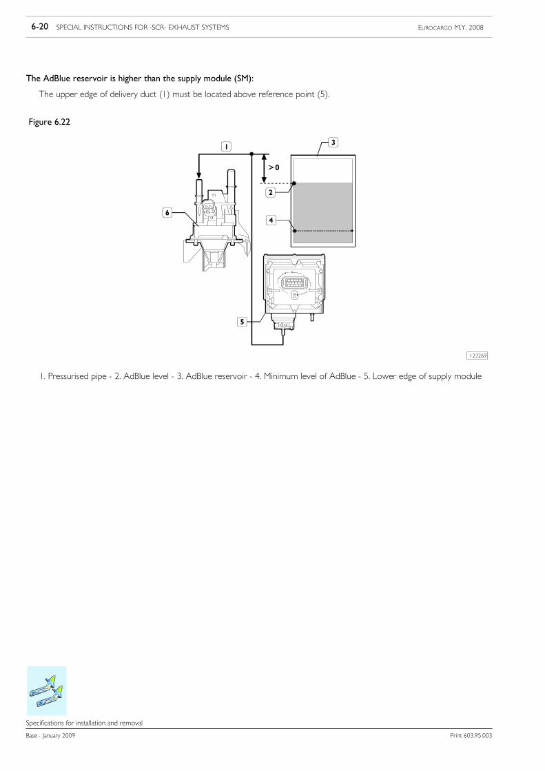
6-20 SPECIAL INSTRUCTIONS FOR -SCR- EXHAUST SYSTEMS EUROCARGO M.Y. 2008
Base - January 2009 Print 603.95.003
Specifications for installation and removal
The AdBlue reservoir is higher than the supply module (SM):
The upper edge of delivery duct (1) must be located above reference point (5).
Figure 6.22
123269
1. Pressurised pipe - 2. AdBlue level - 3. AdBlue reservoir - 4. Minimum level of AdBlue - 5. Lower edge of supply module
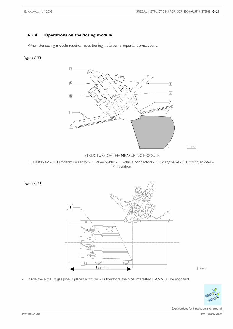
SPECIAL INSTRUCTIONS FOR -SCR- EXHAUST SYSTEMS 6-21EUROCARGO M.Y. 2008
Print 603.95.003 Base - January 2009
Specifications for installation and removal
6.5.4 Operations on the dosing module
When the dosing module requires repositioning, note some important precautions.
Figure 6.23
114743
STRUCTURE OF THE MEASURING MODULE
1. Heatshield - 2. Temperature sensor - 3. Valve holder - 4. AdBlue connectors - 5. Dosing valve - 6. Cooling adapter -7. Insulation
Figure 6.24
117475A "158 mm
- Inside the exhaust gas pipe is placed a diffuser (1) therefore the pipe interested CANNOT be modified.
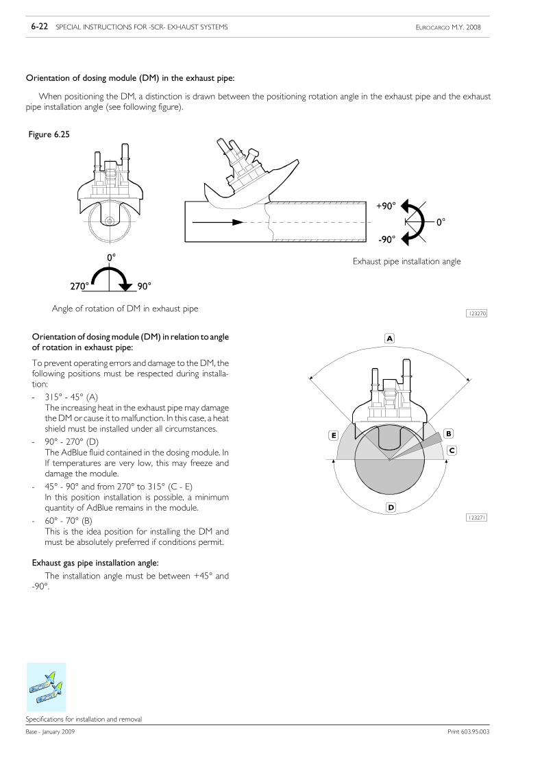
6-22 SPECIAL INSTRUCTIONS FOR -SCR- EXHAUST SYSTEMS EUROCARGO M.Y. 2008
Base - January 2009 Print 603.95.003
Specifications for installation and removal
Orientation of dosing module (DM) in the exhaust pipe:
When positioning the DM, a distinction is drawn between the positioning rotation angle in the exhaust pipe and the exhaustpipe installation angle (see following figure).
Figure 6.25
123270Angle of rotation of DM in exhaust pipe
Exhaust pipe installation angle
123271
Orientation of dosingmodule (DM) in relation to angleof rotation in exhaust pipe:
To prevent operating errors and damage to the DM, thefollowing positions must be respected during installa-tion:
- 315° - 45° (A)The increasing heat in the exhaust pipe may damagetheDM or cause it to malfunction. In this case, a heatshield must be installed under all circumstances.
- 90° - 270° (D)The AdBlue fluid contained in the dosing module. InIf temperatures are very low, this may freeze anddamage the module.
- 45° - 90° and from 270° to 315° (C - E)In this position installation is possible, a minimumquantity of AdBlue remains in the module.
- 60° - 70° (B)This is the idea position for installing the DM andmust be absolutely preferred if conditions permit.
Exhaust gas pipe installation angle:
The installation angle must be between +45° and-90°.
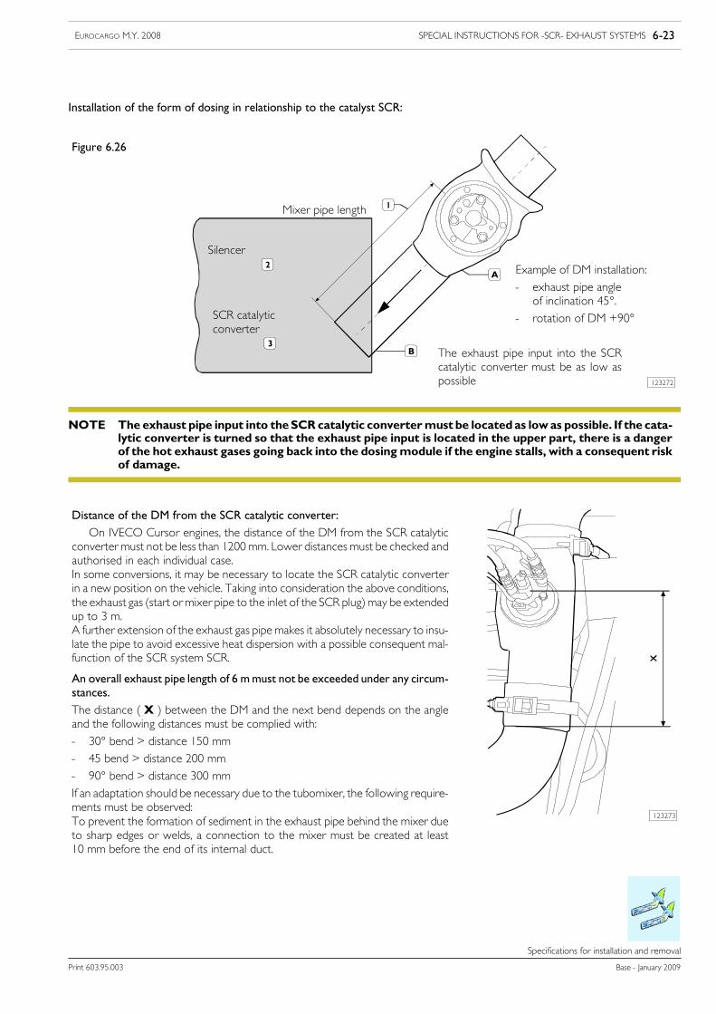
SPECIAL INSTRUCTIONS FOR -SCR- EXHAUST SYSTEMS 6-23EUROCARGO M.Y. 2008
Print 603.95.003 Base - January 2009
Specifications for installation and removal
Installation of the form of dosing in relationship to the catalyst SCR:
Figure 6.26
123272
Mixer pipe length
Silencer
Example of DM installation:
- exhaust pipe angleof inclination 45°.
- rotation of DM +90°SCR catalyticconverter
The exhaust pipe input into the SCRcatalytic converter must be as low aspossible
The exhaust pipe input into theSCR catalytic convertermust be locatedas lowas possible. If the cata-lytic converter is turned so that the exhaust pipe input is located in the upper part, there is a dangerof the hot exhaust gases going back into the dosingmodule if the engine stalls, with a consequent riskof damage.
NOTE
123273
Distance of the DM from the SCR catalytic converter:
On IVECO Cursor engines, the distance of the DM from the SCR catalyticconverter must not be less than 1200 mm. Lower distances must be checked andauthorised in each individual case.In some conversions, it may be necessary to locate the SCR catalytic converterin a new position on the vehicle. Taking into consideration the above conditions,the exhaust gas (start ormixer pipe to the inlet of the SCR plug)may be extendedup to 3 m.A further extension of the exhaust gas pipe makes it absolutely necessary to insu-late the pipe to avoid excessive heat dispersion with a possible consequent mal-function of the SCR system SCR.
An overall exhaust pipe length of 6 mmust not be exceeded under any circum-stances.
The distance ( X ) between the DM and the next bend depends on the angleand the following distances must be complied with:
- 30° bend > distance 150 mm
- 45 bend > distance 200 mm
- 90° bend > distance 300 mm
If an adaptation should be necessary due to the tubomixer, the following require-ments must be observed:To prevent the formation of sediment in the exhaust pipe behind the mixer dueto sharp edges or welds, a connection to the mixer must be created at least10 mm before the end of its internal duct.
6-24 SPECIAL INSTRUCTIONS FOR -SCR- EXHAUST SYSTEMS EUROCARGO M.Y. 2008
Base - January 2009 Print 603.95.003
Specifications for installation and removal
If the dosing module is moved, the pipes and electrical wiring must be modified.NOTE
6.5.5 Operations on exhaust pipes
The exhaust pipe layout cannot be changed without the approval of IVECO.NOTE
The exhaust pipe can be modified paying attention to the following warnings:
- type approved (homologated) counter-pressures must be respectedwhen determining the exhaust pipe route. Form bendswithangles greater than 90° and radius of curvature greater than 2.5 times the pipe diameter. Keep the exhaust pipe far enough awayfrom rubber or plastic parts and fit heat shields if necessary.
- it is not permitted to use pipes with diameters, thicknesses and materials other than those used for the original equipment.- it is permitted to use hoses with limited lengths.- in some conversions, it may be necessary to locate the SCR catalytic converter in a new position on the vehicle. Taking intoconsideration the above conditions, exhaust gas pipe (start of mixer pipe to the SCR plug intake) may be extended up to 3 m.
- a further extension of the exhaust gas pipe makes it absolutely necessary to insulate the pipe to avoid excessive heat dispersionwith a possible consequent malfunction of the SCR system.
An overall exhaust pipe length of 5 m must not be exceeded under any circumstances.
Electrical wiring:
- it is only possible to lengthen cables for the temperature sensors.- it is not possible to alter the length of the Nox sensor cable.
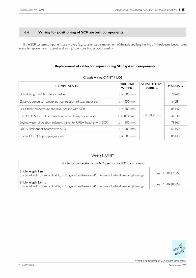
SPECIAL INSTRUCTIONS FOR -SCR- EXHAUST SYSTEMS 6-25EUROCARGO M.Y. 2008
Print 603.95.003 Base - January 2009
Wiring for positioning of SCR system components
Wiring for positioning of SCR system components
6.6 Wiring for positioning of SCR system components
If the SCR system components are moved (e.g. total or partial movement of the rails and lengthening of wheelbase), Iveco makesavailable replacement material and wiring to ensure final product quality.
Replacement of cables for repositioning SCR system components
Chassis wiring C-MET / UDS
COMPONENTSORIGINALWIRING
SUBSTITUTIVEWIRING
MARKING
SCR dosing module solenoid valve L = 800 mm 78266
Catalytic converter sensor out connection (4-way super seal) L = 250 mm st 59
Urea tank temperature and level sensor with SCR L = 300 mm 85142
C-EFM/UDS to CILC connection cable (4-way super seal) L = 1000 mm L = 5000 mm 44030
Engine water circulation solenoid valve for UREA heating with SCR L = 500 mm 78267
UREA filter outlet heater with SCR L = 400 mm 61150
Control for SCR pumping module L = 800 mm 85140
Wiring E-A/MET
Bridle for connection from NOx sensor to EFM control unit
Bridle length 2 m.(to be added to standard cable, in longer wheelbases and/or in case of wheelbase lengthening)
des. n° 504279753
Bridle length 2.6 m.(to be added to standard cable, in longer wheelbases and/or in case of wheelbase lengthening)
des. n° 504280652
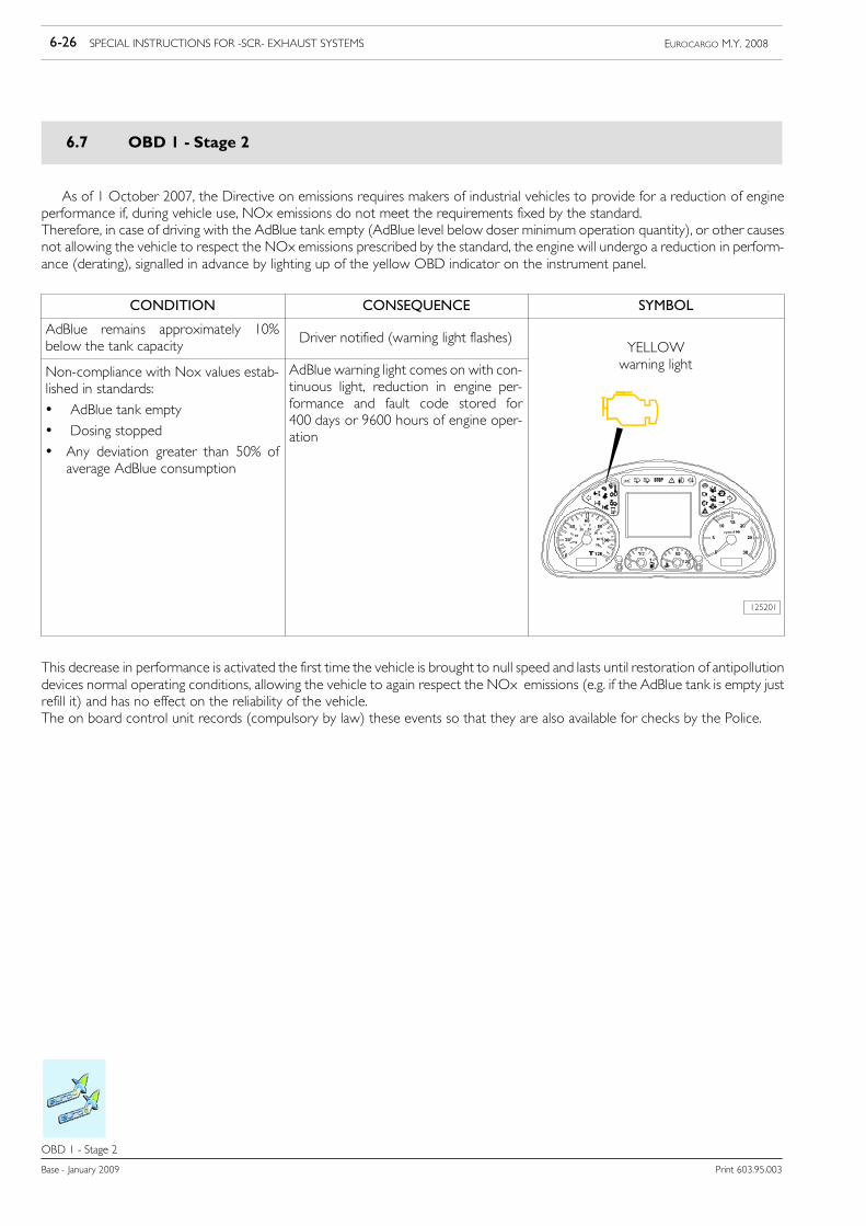
6-26 SPECIAL INSTRUCTIONS FOR -SCR- EXHAUST SYSTEMS EUROCARGO M.Y. 2008
Base - January 2009 Print 603.95.003
OBD 1 - Stage 2
OBD 1--- Stage 2
6.7 OBD 1 - Stage 2
As of 1 October 2007, the Directive on emissions requires makers of industrial vehicles to provide for a reduction of engineperformance if, during vehicle use, NOx emissions do not meet the requirements fixed by the standard.Therefore, in case of driving with the AdBlue tank empty (AdBlue level below doser minimum operation quantity), or other causesnot allowing the vehicle to respect the NOx emissions prescribed by the standard, the engine will undergo a reduction in perform-ance (derating), signalled in advance by lighting up of the yellow OBD indicator on the instrument panel.
CONDITION CONSEQUENCE SYMBOL
AdBlue remains approximately 10%below the tank capacity
Driver notified (warning light flashes)YELLOW
Non-compliance with Nox values estab-lished in standards:
• AdBlue tank empty
• Dosing stopped
• Any deviation greater than 50% ofaverage AdBlue consumption
AdBlue warning light comes on with con-tinuous light, reduction in engine per-formance and fault code stored for400 days or 9600 hours of engine oper-ation
warning light
125201
This decrease in performance is activated the first time the vehicle is brought to null speed and lasts until restoration of antipollutiondevices normal operating conditions, allowing the vehicle to again respect the NOx emissions (e.g. if the AdBlue tank is empty justrefill it) and has no effect on the reliability of the vehicle.The on board control unit records (compulsory by law) these events so that they are also available for checks by the Police.