powerpoint template for hilumi collaborators
TRANSCRIPT

CERN-ACC-SLIDES-2014-0081
HiLumi LHCFP7 High Luminosity Large Hadron Collider Design Study
Presentation
HL - LHC Optics and Layout Overview
De Maria, R (CERN)
12 November 2013
The HiLumi LHC Design Study is included in the High Luminosity LHC project and ispartly funded by the European Commission within the Framework Programme 7
Capacities Specific Programme, Grant Agreement 284404.
This work is part of HiLumi LHC Work Package 2: Accelerator Physics & Performance.
The electronic version of this HiLumi LHC Publication is available via the HiLumi LHC web site<http://hilumilhc.web.cern.ch> or on the CERN Document Server at the following URL:
<http://cds.cern.ch/search?p=CERN-ACC-SLIDES-2014-0081>
CERN-ACC-SLIDES-2014-0081

The HiLumi LHC Design Study is included in the High Luminosity LHC project and is partly funded by the European Commission within the Framework Programme 7 Capacities Specific Programme, Grant Agreement 284404.
HL-LHC Optics and Layout
Overview
R. De Maria for the HL-LHC teams
Thanks to R. Appleby, G. Arduini, A. Bogomyakov, O. Brüning, R. Bruce, R. Calaga, F. Cerutti, S. Chemly, B. Dalena, L. Esposito, S. Fartoukh, P. Fessia, P. Ferracin, M. Fitterer, M. Giovannozzi, R. Jones, S. Kelly, M. Korostelev, C. Milardi, J. Payet, T. Pieloni, H. Prin,
S. Redaelli, L. Rossi, S. Russenshuck, M. Thomas, L. Thompson, E. Todesco, R. Tomas.

LHC Ring and Interaction Region (IR) layout
2
. High luminosity experiments ATLAS and CMS relies on (compared to nominal): • Large flux of debris irradiated from the
interaction point (IP) • Smaller spot size (small β*) at the IP • Crab cavities for luminous region
optimization. Hardware, layout and optics of the interaction region (IR) around IP1 and IP5 needs upgrade and review.
Half interaction region
Triplet area Matching section Dispersion suppressor

ATS principle: barc ×4 in 81/12/45/56
3
β*reach: optics S. Fartoukh, Chamonix 2011, 2012 and reference therein
(A)chromatic
(T)elescopic (S)queeze
Low β* traditionally limited by optics flexibility and chromatic aberrations. ATS optics established on paper and with beam in the present LHC. Baseline β*: 15 cm, or 30/7.5 cm Ultimate β*: 10 cm or 20/5 cm

4
Leveling Experiments’ useful luminosity limited by number of event per crossing (pile-up): 140 to 200. Luminosity needs to be leveled: • IP1-5: leveling by β* with a combination of local
and ATS squeeze • IP8: β* or separation or a combination of them.
Main challenge: keep beam into collision for long time (~1 µm stability) while varying quadrupole and orbit corrector strengths in order to avoid: • luminosity loss, • lifetime losses, • Instabilities.
IP1 and IP5
IP8
𝐿lev ~ 𝑛pileup ∙ 𝑛bunches

IR4,6
IR2
IR8
IR1,5
5
Optics Transitions Overview
inj, ramp end of ramp (tune jump)
end of ramp (triplet str.)
end of ramp (triplet str.)
pre-squeeze
squeeze (ion)
vdm
vdm
ATS squeeze round, flat(hv)
vdm squeeze (ion)
ATS squeeze round, flat(hv)
ATS squeeze round, flat(hv)
squeeze inj, ramp
inj, ramp
inj, ramp

Collision low-β optics parameters Name IP1-5 IP2 IP8
β* [cm]
Angle [murad]
sep [mm]
β* [m]
Angle [murad]
sep [mm]
β* [m]
Angle [murad]
sep [mm]
Round 15 590 0.75 10 340 2 3 340 2
flat 7.5, 30 550 0.75 10 340 2 3 340 2
flathv 30, 7.5 550 0.75 10 340 2 3 340 2
sround 10 720 0.75 10 340 2 3 340 2
sflat 5, 20 670 0.75 10 340 2 3 340 2
sflathv 20, 5 670 0.75 10 340 2 3 340 2
ions 44 350 0.75 0.5 340 2 0.5 340 2
6
• Optics available under /afs/cern.ch/eng/lhc/optics/HLLHCV1.0 1)
• Baseline round and flat optics at 15 cm or 7.5/30 cm. • Ultimate squeeze for improved performance provided tight collimation settings. • Optics for ion operations with low β* in all Ips.
1) R. De Maria, S. Fartoukh, A. Bogomiakov, M. Korostelev, HLLHCV1.0:…, IPAC13)

Supporting optics parameters Name IP1-5 IP2 IP8
Beta* [m]
Angle [µrad]
sep [mm]
Beta* [m]
Angle [µrad]
sep [mm]
Beta* [m]
Angle [µrad]
sep [mm]
inj_18m (in prep.) 18 340 2 10 340 2 10 340 2
inj_11m (in prep.) 11 340 2 10 340 2 10 340 2
inj 6 490 2 10 340 2 10 340 2
endoframp 6 360 2 10 340 2 10 340 2
Presqueeze_3000 3 360 0.75 10 340 2 3 340 2
presqueeze 44 360 0.75 10 340 2 3 340 2
7
• Optics available under /afs/cern.ch/eng/lhc/optics/HLLHCV1.01). • Injection optics optimized for aperture. • End of ramp optics for tune jump and IR2-8 triplet relaxation. • Pre-squeeze optics to enable ATS mechanism. • Van-der-Mer scan optics requested 15 to 20 m at collision energy under study.
1) R. De Maria, S. Fartoukh, A. Bogomiakov, M. Korostelev, HLLHCV1.0:…, IPAC13)

LHC Ring and Interaction Region (IR) layout
8
. High luminosity experiments ATLAS and CMS relies on (compared to nominal): • Large flux of debris irradiated from the
interaction point (IP) • Smaller spot size (small β*) at the IP • Crab cavities for luminous region
optimization. Hardware, layout and optics of the interaction region (IR) around IP1 and IP5 needs upgrade and review.
Half interaction region
Triplet area Matching section Dispersion suppressor

9
Triplet and D1 (β* = 15cm) 12σ halo
Triplets: octagonal beam screen with W liner baseline: • Q1: 98 mm • Q2-Q3-D1: 118 mm Manufacturing tolerances not included, to be specified with hardware tests (R. Kersevan) • TAS: Circular aperture 60
mm
x [m
]
s [m]

10
Triplet and D1 (β* = 30/7.5cm)
Smaller crossing angle and beam size in the crossing plane.
x [m
]
s [m]
Same aperture supports flat β aspect ratio

11
Triplet and D1 (β* = 30/7.5cm)
Large beam size in the other plane…
y [m]
s [m]
Same aperture supports flat β aspect ratio

Name Type Mag. Length
Strength
Q1,3 a/b (MQXF)
Quad. 4.002 m 140 T/m
Q2a/b (MQXF)
Quad. 6.792 m 140 T/m
D1 (MBXA)
Dip. 6.69 m 5.2 T
12
Triplet - D1 Specifications Triplet length optimized: • with interconnects length given by WP3, • for aperture margins, • for strength margins on matching
quadrupoles with ATS phase advances. Different optimization (~ cm) needed on changing conditions.
Dipole correctors for: • Crossing scheme (closed in D2) • Transverse triplet misalignment Non-linear corrector resulting to compensate triplet and D1 field imperfections based on estimates. See M. Giovanozzi’s talk.
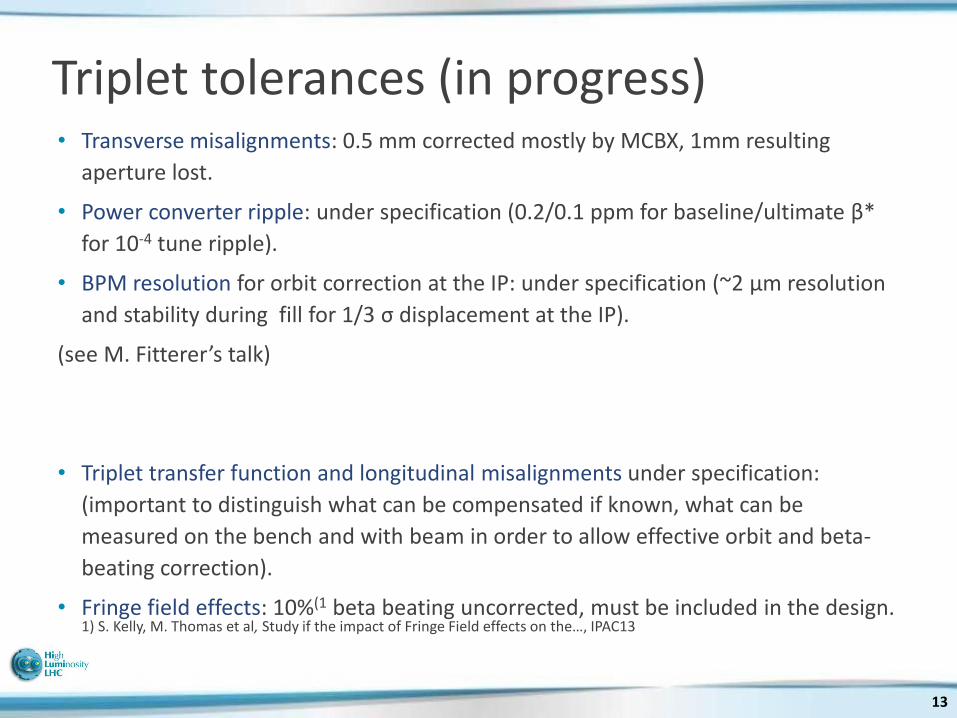
• Transverse misalignments: 0.5 mm corrected mostly by MCBX, 1mm resulting
aperture lost.
• Power converter ripple: under specification (0.2/0.1 ppm for baseline/ultimate β*
for 10-4 tune ripple).
• BPM resolution for orbit correction at the IP: under specification (~2 µm resolution
and stability during fill for 1/3 σ displacement at the IP).
(see M. Fitterer’s talk)
• Triplet transfer function and longitudinal misalignments under specification:
(important to distinguish what can be compensated if known, what can be
measured on the bench and with beam in order to allow effective orbit and beta-
beating correction).
• Fringe field effects: 10%(1 beta beating uncorrected, must be included in the design. 1) S. Kelly, M. Thomas et al, Study if the impact of Fringe Field effects on the…, IPAC13
13
Triplet tolerances (in progress)

14
TAN – Q4 (β* = 15cm)
Name (Coil Ap. [mm])
Beam Aperture Type, half h, w [mm]
TAN Ellipse 41, 371)
Crab Round, 42
D2 (105) RectEllipse, 41, 32 (H)
Q4 (90) RectEllipse, 37, 32 (HV)
Q5 (70 RectEllipse, 24, 28.9 (HV)
Q6 (56) RectEllipse, 17.7, 22.6 (HV)
TAN D2 Crab Q4
z [m]
x[m
]
1) TAN aperture under review in the context of energy deposition studies (L. Esposito)

15
TAN – Q4 (β* = 30, 7.5 cm)
Name (Coil Ap.)
Beam Aperture Type, half h, w [mm]
TAN Ellipse 41, 37
Crab Round, 42
D2 (105) RectEllipse, 41, 32
Q4 (90) RectEllipse, 37, 32 (HV)
Q5 (70 RectEllipse, 24, 28.9 (HV)
Q6 (56) RectEllipse, 17.7, 22.6 (HV)
TAN D2 Crab Q4
z [m]
x[m
]

16
TAN – Q4 (β* = 7.5, 30 cm)
Name (Coil Ap.)
Beam Aperture Type, half h, w [mm]
TAN Ellipse 41, 37
Crab Round, 42
D2 (105) RectEllipse, 41, 32
Q4 (90) RectEllipse, 37, 32 (HV)
Q5 (70 RectEllipse, 24, 28.9 (HV)
Q6 (56) RectEllipse, 17.7, 22.6 (HV)
TAN D2 Crab Q4
z [m]
x[m
]
Aperture bottlenecks with flat optics.

• D2: 2-in-1(186mm) , 35 Tm, 105 mm
aperture (length, strength, field quality,
aperture under review)
• Crab cavities: 3 (4 from next version)
modules for 12.5 MV (See. B. Dalena’s
talk)
• Wires: 2 or 1 per beam per IR, position
to be specified not yet included in the
lattice.
17
Matching section (TAN – D2 - Crabs)
TAN: neutral protection; W masks: in front MS cryostats under study (F. Cerutti, L. Esposito) TCL: help natural protection with horizontal crossing; TCT: protect triplet from incoming beam, additional TCT under study (see S. Redaelli talk);

18
Matching section (IR1, IR5) Q4: need extra aperture for beam and radiation (MQYY1) type 90 mm) Q5: need MQY aperture and MQML length -> MQYL1). E. Todesco proposed: • an MQY at 200 T/m (might be tight in strength) • 2 MQYY (ideal for energy deposition and
strength, but low current field must be well under control)
Q6: no changes, offered 1.9 K cooling and additional strength.
Name Apert. Length Strength
Q4 (MQYY) 90 mm 3.5 m 125 T/m
Q5 (MQYL) 70 mm 4.8 m 160 T/m
Q6 (MQML) 56 mm 4.8 m 160 T/m
M. Korostelev Q4
Q5
Q6 Ideal choice for integrated strength after final optics sets.
1) S. Fartoukh, SLHC Pr. 49

19
Matching section (IR6) Q5 in IR6: exiting one too weak to support ATS1) telescopic squeeze starting β*=20 cm (MQYL in baseline, proposed MQY at 200 T/m should fit the specification) However phase advance between MKD and TCT in Point 5 may be critical 2), tunability of IR6 optics under study.
Optics β* [cm] ATS scaling factor
Q6 Strength (160 T/m max)
Round 15/15 3/3 117 T/m
Flat 30/7.5 1.5/6 128 T/m
Flathv 7.5/30 6/1.5 133 T/m
sRound 10/10 4/4 121 T/m
sFlat 20/5.0 2.2/9 131 T/m
sFlathv 5.0/20 9/2.2 141 T/m
M. Korostelev
1) S. Fartoukh, Chamonix 2011. 2) See L. Lari, talk

20
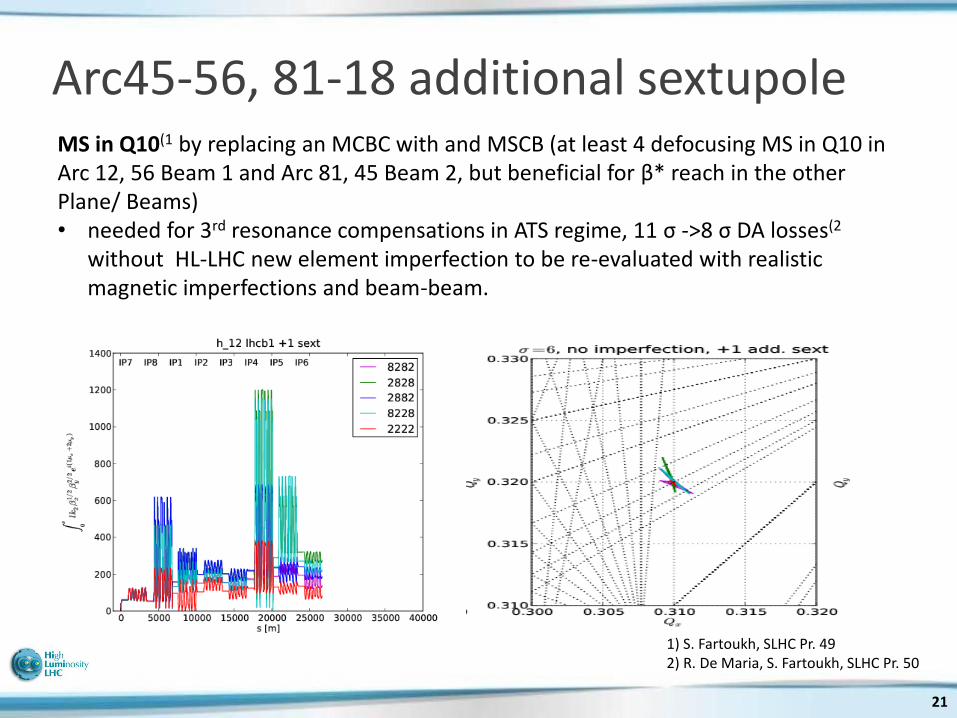
Arc45-56, 81-18 additional sextupole MS in Q10(1 by replacing an MCBC with and MSCB (at least 4 defocusing MS in Q10 in Arc 12, 56 Beam 1 and Arc 81, 45 Beam 2, but beneficial for β* reach in the other Plane/ Beams): • needed for 3rd resonance compensations in ATS regime, 11 σ ->8 σ DA losses(2
without HL-LHC new element imperfection to be re-evaluated with realistic magnetic imperfections and beam-beam.
1) S. Fartoukh, SLHC Pr. 49 2) R. De Maria, S. Fartoukh, SLHC Pr. 50
21
Arc45-56, 81-18 additional sextupole MS in Q10(1 by replacing an MCBC with and MSCB (at least 4 defocusing MS in Q10 in Arc 12, 56 Beam 1 and Arc 81, 45 Beam 2, but beneficial for β* reach in the other Plane/ Beams) • needed for 3rd resonance compensations in ATS regime, 11 σ ->8 σ DA losses(2
without HL-LHC new element imperfection to be re-evaluated with realistic magnetic imperfections and beam-beam.
1) S. Fartoukh, SLHC Pr. 49 2) R. De Maria, S. Fartoukh, SLHC Pr. 50

• Validation phase of HLLHCV1.0.
• Critical areas (neutral protection, magnet types,
optics transitions, tolerances) being addressed.
• HLLHCV1.0 remains stable version until full
validation among all WPs.
• Crab cavity kick optimized optics remains as
separate branch.
• Changes like: masks, 4 cavities, Q5 magnet type,
solution for MS in Q10, wires, official naming will
be included in the next versions.
22
Conclusion

23
Backup

24
HL-LHC layout radiation protection
L. Esposito, F. Cerutti
• HL-LHC triplet peak dose triplet at same level of present one but with 10 times more integrated luminosity
• Below 2 mW/cm3 at 5 10 34 cm-2s-1
• Below 25 MGy after 3000 fb-1
• New TAN being specified • Fixed mask in front of Q2, Q4, Q5 • Additional TCL • Below 1 mW/cm3 at 5 10 34 cm-2s-1
• Below 20 MGy after 3000 fb-1
0
10
20
30
40
20 30 40 50 60 70 80
pea
k d
ose
[M
Gy]
distance from IP [m]
peak dose longitudinal profile
7+7 TeV proton interactionsHL-LHC at 3000 fb
-1 - 10 cm gap
LHC at 300 fb-1
beam
screen
W absorbers
cold bore
cooling
channel

25
Collimation and protection • Minimum collimator aperture defined by impendence , orbit control to
avoid lifetime spikes and protection from failures (async. dump).
• Settings do not scale with beam emittance in practice.
Aperture at 3.5 µm , 7TeV
LHC Design Report
HL-LHC Baseline
TCP IR7 6.0 5.7
TCS IR7 7.0 7.7
TCS IR6 7.5 8.5
TCDQ IR6 8.0 9.0
TCT IR1/5 8.3 10.5
Min Aperture IR1/5 8.4 12
• Upgrade to metallic collimators or
equivalent to keep acceptable impedance is needed.
• E-lens can be useful to control loss. spikes (in particular with crab cavities)
• Button BPMs for accurate and fast alignment.
Aperture tolerance being re-evaluated based on experience and no unknown non-conformities. S. Redaelli, M. Giovannozzi, collimation and optics team.

26
Crossing angle and long range beam beam
• Baseline: 590 µrad for round β*, 540 µrad for flat β*.
• Target of 10 σ with long range wire compensators.
• With β* leveling minimum beam-beam separation occurs
only at about 1.2 1011 ppb:
• Round β*: more performance, full HV crossing BBLR
compensation;
• Flat β*: smaller crossing angle, less crab voltage,
potentially competitive with wire compensation.
S. Fartoukh, Chamonix 2011
T. Pieloni, D. Banfi and beam-beam team
Beam beam effects (pacman, orbit, DA) and wire compensation under study.

Performance of different scenarios (6.5 TeV)
Nb coll
[1011]
e*n coll
[mm]
Min b*
(xing / sep)
[cm]
angle
[mrad]
# Coll.
Bunches
IP1,5
Lpeak
[1034
cm-2s-1]
Llev
[1034
cm-2s-1]
Lev.
time
[h]
Opt. Fill
length
[h]
η6h
[%]
ηopt
[%]
Avg. Peak-
pile-up
density
[ev./mm]
RLIUP2 1.5 1.36) 15/15 366 2592 17.6 4.8 4.4 5.8 64.6 64.6 0.88
LIU-BCMS 1.9 1.656) 13.5/13.53) 420 2592 21.7 4.8 6.3 7.5 61.0 58.4 0.94
LIU-STD 1.9 2.26 14.5/14.53) 474 2736 15.8 5.06 5.3 6.9 58.2 57.5 0.97
HL-Flat 2.2 2.5 30/0.0751) 3482)/550 2736 17.2 5.06 6.5 8.0 57.8 54.5 1.05
HL-Round 2.2 2.5 15/15 4902)/590 2736 18.7 5.06 6.8 8.2 57.8 54.0 1.05
LIU-BCMS 1.9 1.65 13.5/13.53) 420 2592 21.7 6.875) 4.3 6.2 52.2 52.2 1.34
HL-Round 2.2 2.5 15/153) 490 2736 17.2 7.245) 5.4 7.3 48.8 48.4 1.37
HL-SRound 2.2 2.5 10/104) 600 2736 18.7 7.245) 4.4 6.7 47.7 46.4 1.55
1) compatible with crab kissing scheme (S. Fartoukh). 2) BBLR wire compensator assumed to allow 10σ. 3) b* could be reduced to 14.5 and 13.5 cm at constant aperture. 4) Ultimate collimation settings. 5) Pile-up limit at 200 event/ crossing. 6) 30% blow-up from IBS makes 1.85 um is more likely

Performance of different scenarios (7 TeV)
Nb coll
[1011]
e*n coll
[mm]
Min b*
(xing / sep)
[cm]
angle
[mrad]
# Coll.
Bunches
IP1,5
Lpeak
[1034
cm-2s-1]
Llev
[1034
cm-2s-1]
Lev.
time
[h]
Opt. Fill
length
[h]
η6h
[%]
ηopt
[%]
Avg. Peak-
pile-up
density
[ev./mm]
RLIUP2 1.5 1.36) 15/15 341 2592 19.0 4.8 4.7 6.0 63.4 63.4 0.94
LIU-BCMS 1.9 1.656) 13.5/13.5 405 2592 23.4 4.8 6.7 7.8 61.0 57.5 0.98
LIU-STD 1.9 2.26 14.5/14.5 457 2736 17.0 5.06 5.7 7.2 58.2 56.4 1.01
HL-Flat 2.2 2.5 30/0.0751) 3352)/550 2736 18.6 5.06 7.0 8.4 57.8 53.5 1.12
HL-Round 2.2 2.5 15/15 4762)/590 2736 20.1 5.06 7.3 8.6 57.8 53.1 1.03
LIU-BCMS 1.9 1.65 13.5/13.5 579 2592 23.4 6.875) 4.6 6.4 51.4 51.3 1.34
HL-Round 2.2 2.5 15/15 473 2736 20.1 7.245) 4.8 7.0 48.2 47.4 1.37
HL-SRound 2.2 2.5 10/104) 600 2736 26.8 7.245) 5.8 7.6 47.6 45.7 1.55
1) compatible with crab kissing scheme (S. Fartoukh) 2) BBLR wire compensator assumed to allow 10σ 3) b* could be reduced to 14.5 and 13.5 cm at constant aperture 4) Ultimate collimation settings 5) Pile-up limit at 200 event/ crossing 6) 30% blow-up from IBS makes 1.85 um is more likely

29
Fill evolutions 6.5 TeV (1)

30
Fill evolutions 6.5 TeV (2)

31
Fill evolutions 6.5 TeV (3)