powerstat operating manual - nuvantnuvant.com/pdfs/powerstat manual_potentiostat.pdf · figure 7...
TRANSCRIPT

PowerStat Operating Manual
1 NuVant Systems Inc. Release - 3.0

PowerStat Operating Manual
2 NuVant Systems Inc. Release - 3.0
OPERATING MANUAL
VERSION 3.0
PowerStat
©Copyright 2003, 2005, 2011, 2012
NuVant Systems, Inc. Crown Point, Indiana
All rights reserved. No part of this publication may be reproduced, transmitted, transcribed, stored on a retrieval system or translated into any language, in any form or by any means, electronic, mechanical, manual or otherwise, without the prior consent of NuVant Systems, Inc. NuVant Systems, Inc. makes no representations or warranties with respect to the contents hereof and specifically disclaims any implied warranties of merchantability and fitness for a particular purpose. Furthermore, NuVant Systems, Inc. reserves the right to revise this publication and to make changes from time to time in the content hereof without obligation to notify any person of such revision or changes.
Program License Agreement
Do not use the software package until you have read the license agreement. If you use the program, NuVant Systems will assume that you have agreed to, and as such are, bound by this standard agreement. If you do not accept the terms of this license, you must return the package unused to the party from whom you received it. The program contained in this package is provided to the end user as a single program for use on a single machine and not for distribution to other machines or parties.
PowerStat Operating Manual
3 NuVant Systems Inc. Release - 3.0
TABLE OF CONTENTS
MAINS SUPPLY INPUT SPECIFICATIONS ........................................................................... 8
Mains Power Cable Manufacturer Data ...................................................................................... 9
INTENDED USE OF EQUIPMENT ........................................................................................... 9
SAFETY ......................................................................................................................................... 9
General ........................................................................................................................................ 9
Material Safety Data Sheets ...................................................................................................... 10
Personal Protection Equipment ................................................................................................. 10
Computer Control and System Safety ....................................................................................... 10
Grounding ................................................................................................................................. 10
ESD Protection .......................................................................................................................... 10
AC Supply Voltage ................................................................................................................... 11
Avoid Using Unsafe Equipment ............................................................................................... 11
Technical Assistance Contact Information ............................................................................... 11
Accessory Cables ...................................................................................................................... 11
MECHANICAL SPECIFICATIONS AND HANDLING ....................................................... 12
Overall Dimensions and Weight ............................................................................................... 12
Placement and Surroundings of the PowerStat ......................................................................... 12
ENVIRONMENTAL CONDITIONS ........................................................................................ 12
Normal Environmental Conditions for PowerStat .................................................................... 12
HARDWARE AND SOFTWARE CONVENTIONS ............................................................... 13
Hardware Conventions .............................................................................................................. 13
Software Naming Conventions ................................................................................................. 13
HARDWARE INSTALLATION ............................................................................................... 13
Description of Controls and Connections ................................................................................. 13
PowerStat Front Panel ............................................................................................................... 13
Procedure for Connection of Electrode Cables to an Electrochemical Device ......................... 15
PowerStat Back Panel ............................................................................................................... 16
CLEANING AND MAINTENANCE ........................................................................................ 17
SERVICE AND REPAIR ........................................................................................................... 17

PowerStat Operating Manual
4 NuVant Systems Inc. Release - 3.0
SOFTWARE INSTALLATION AND OPERATION .............................................................. 18
Software Installation: ................................................................................................................ 18
ON BOARD FUNCTION GENERATOR VS CPU TIMING ................................................. 19
Operation of Control and Data Acquisition Software ............................................................. 20
1.1.1. powerstat-05 Start Screen ....................................................................................... 20 1.1.2. Recipe Editor .............................................................................................................. 25 1.1.3. Running The PowerStat .............................................................................................. 61
IV curve..................................................................................................................................... 67 1.1.4. Selecting desired axis ................................................................................................. 68 1.1.5. Examining specific scans on a CV ............................................................................. 68 1.1.6. Filtering the Data ........................................................................................................ 68 1.1.7. Analyzing the Data ..................................................................................................... 69
INDEX .......................................................................................................................................... 72

PowerStat Operating Manual
5 NuVant Systems Inc. Release - 3.0
TABLE OF FIGURES Figure 1 PowerStat Front Panel ........................................................................................ 14 Figure 2 PowerStat Back Panel......................................................................................... 16 Figure 3 Location of Software .......................................................................................... 20 Figure 4 powerstat-05 Start Screen, 1st run of software ............................................... 21 Figure 5 New Directory Created on Desktop ................................................................... 21 Figure 6 Recipe Naming ................................................................................................... 22 Figure 7 Recipe File Name with an established path. ....................................................... 22 Figure 8 Multiple Active Devices ..................................................................................... 23 Figure 9 powerstat-05 Start Screen For Two Instruments on the Same PC ................ 24 Figure 10 Run powerstat Windows for Two Simultaneous Instruments ...................... 25 Figure 11 powerstat-05 Recipe Editor with Unedited New Recipe Loaded ................. 26 Figure 12 powerstat-05 Recipe Editor Button controls ................................................ 27 Figure 13 Editing Step Number Jump Step Window .................................................... 27 Figure 14 ? Control Type Pop Up Help Window ......................................................... 28 Figure 15 ? Signal Type Pop Up Help Window ........................................................... 28 Figure 16 Constant Voltage (Potentiostat) Example Entry Field Item Numbers ............. 29 Figure 17 Time Based Constant Current (Galvanostat) Example Entry Field Item
Numbers .................................................................................................................... 30 Figure 18 Galvanostat Battery Cycling with Voltage Target Control, Showing Example
OCV Step Entry Fields. ............................................................................................ 31 Figure 19 Selecting a Recipe to Run From the powerstat-05 Start Screen ................... 32 Figure 20 Observing the Open Circuit Potential of a Cell ................................................ 33
Figure 21 Duplicate Step Creation - Click ................................................................ 34 Figure 22 Duplicate Step Completed ................................................................................ 35 Figure 23 Voltage Target Constant Current Example Discharge Step Entry Field Item
Numbers .................................................................................................................... 36 Figure 24 powerstat-05 Recipe Editor / I vs. t Graph View of Voltage Target Constant
Current Example OCV and Discharge Steps ............................................................ 37 Figure 25 Voltage Target Constant Current Example Charge Step Entry Field Item
Numbers .................................................................................................................... 38 Figure 26 I vs. t Graph View of Voltage Target Constant Current Example OCV,
Discharge and Charge Steps ..................................................................................... 39 Figure 27 Voltage Target Constant Current Example Loop Creation Field Item Numbers
................................................................................................................................... 40 Figure 28 I vs. t Graph View of Voltage Target Constant Current Example with Looped
OCV, Discharge and Charge Steps ........................................................................... 41 Figure 29 Voltage Target Constant Current Example Run powerstat Item Numbers 1-2
................................................................................................................................... 42 Figure 30 Voltage Target Constant Current Example Run Screen Item Numbers 3-5 .... 42 Figure 31 Voltage Target Constant Current Example Run Screen Item Numbers 6-8 .... 43 Figure 32 Voltage Target Constant Current Example Run powerstat ............................ 44 Figure 33 Saving a Recipe With Another Name .............................................................. 45 Figure 34 Voltage Cut Off Constant Current Example Item Numbers ............................ 46
PowerStat Operating Manual
6 NuVant Systems Inc. Release - 3.0
Figure 35 Voltage Cut Off Current Example I vs. t Graph ............................................... 47 Figure 36 Battery Cycling: V vs. mAHr with Voltage Target, Looped, Second Discharge
................................................................................................................................... 48 Figure 37 Battery Cycling V vs. mAHr Graph with Voltage Target, Looped, Three
Complete Cycles ....................................................................................................... 48 Figure 38 Battery Cycling I & V vs. t Graph with Voltage Target, Looped, Three
Complete Cycles ....................................................................................................... 49 Figure 39 Ramp Signal Type ............................................................................................ 49 Figure 40 OCV (Open Circuit Voltage) Signal Type ....................................................... 50 Figure 41 CV Scan Signal Type ....................................................................................... 51 Figure 42 Potential Step Signal Type ............................................................................... 51 Figure 43 Pulse Voltammetry Signal Type ....................................................................... 52 Figure 44 Normal Pulse Voltammetry .............................................................................. 52 Figure 45 Differential Pulse Voltammetry ....................................................................... 53 Figure 46 Square Wave Voltammetry .............................................................................. 53 Figure 47 Predefined Standard Experiments .................................................................... 55 Figure 48 Linear/Cyclic Voltammetry .............................................................................. 56 Figure 49 Chronoamperometry ......................................................................................... 57 Figure 50 Predefined Standard Experiment Step Insertion Window ................................ 58 Figure 51 Range Selection ................................................................................................ 59 Figure 52 Auxiliary Control.............................................................................................. 60 Figure 53 Reviewing the Recipe with the V or I vs. t Graph............................................ 61 Figure 54 Run powerstat ............................................................................................... 62 Figure 55 IR Compensation and Other Experiment Settings............................................ 63 Figure 56 Alarm Indicator and Reset Alarm Button ......................................................... 63 Figure 57 External Input Connector ................................................................................. 64 Figure 58 Manual Controls ............................................................................................... 64 Figure 59 SKIP STEP Window ........................................................................................ 65 Figure 60 Abort State Selection Window ......................................................................... 65 Figure 61 V vs. t Graph Tab of the Run Screen................................................................ 66 Figure 62 Graph Line Style, Width and Color Controls ................................................... 67 Figure 63 IV Curve Program Window.............................................................................. 67 Figure 64 IV Curve Axis Selection ................................................................................... 68 Figure 65 IV Curve Scan Selection .................................................................................. 68 Figure 66 Filter Panel........................................................................................................ 69 Figure 67 IV Curve Integration, Mark Peak ..................................................................... 70 Figure 68 IV Curve Integration, Peak or Valley Selection ............................................... 70 Figure 69 IV Curve Integration, Multiple Peak Selection ................................................ 70 Figure 70 IV Curve Integration, Peak Width Selection .................................................... 71 Figure 71 IV Curve Integration, Analysis Data ................................................................ 71
PowerStat Operating Manual
7 NuVant Systems Inc. Release - 3.0
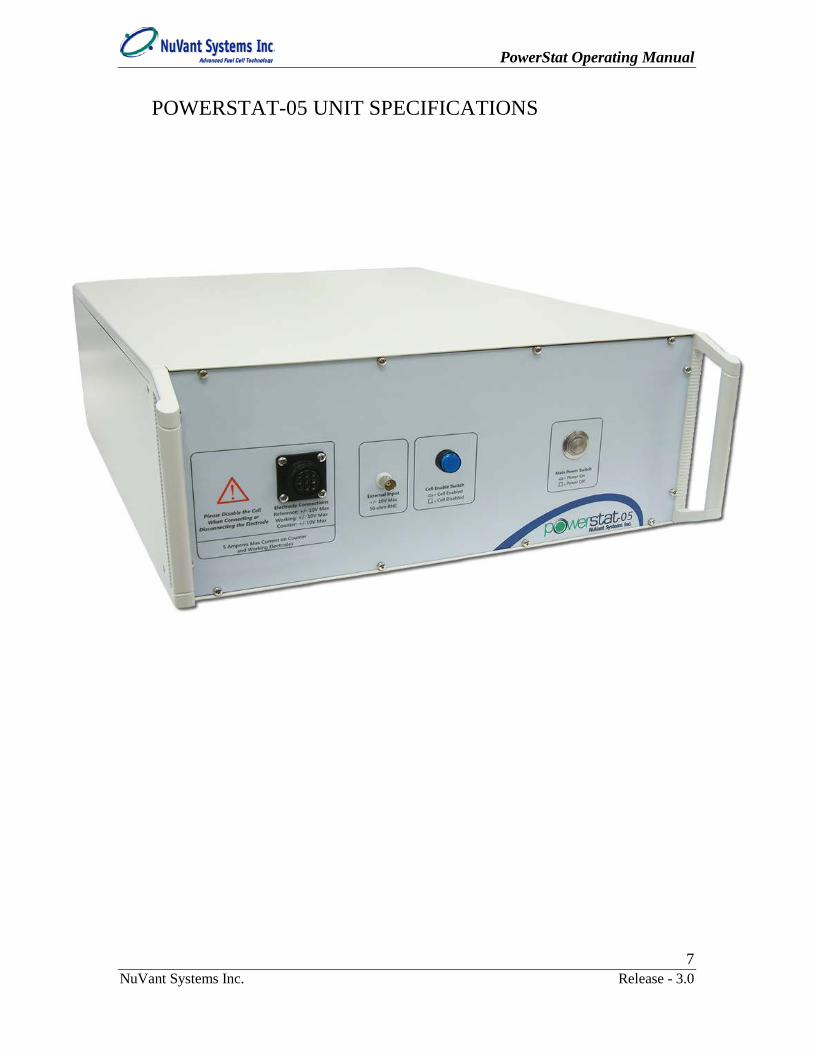
POWERSTAT-05 UNIT SPECIFICATIONS

PowerStat Operating Manual
8 NuVant Systems Inc. Release - 3.0
Cell ControlCompliance Voltage USA ±25 V, IEC ±15 VMax Output Current ±5 A
Rise Time 45 µs for 1 Ohm load (0%-100% signal) Slew Rate 0.8 V/µs
Bandwidth 6 kHz (-3 dB, 1 Ohm load)Applied DC Potential Ranges 1 (±10 V)Applied Potential Resolution 0.3 mV
Applied Potential Accuracy < 0.04% FSRCurrent Autoranging In Galvanostat Mode
Applied DC Current Ranges 4 (±100 mA, ±1 A, ±3 A, ±5 A)Best Applied Current Resolution 3 µA, 0.003% of FSR
Applied Current Accuracy 0.03% of FSRInput Bias Current 500 pAInput Impedance 250 GΩ parallel to 3 pf
Maximum Update Rate 4 µsMaximum Scan Rate 100 V/s
IR Compensation Manual, Potentiostat and Galvanostat Modes, All RangesExternal Control 1 AO, 1 AI, 2 DO
Potential MeasurementMeasured DC Potential Ranges 2 (±50 mV, ±10 V) Autoranging
Resolution 3µV, 300µV (0.006%, 0.003% of FSR)Accuracy 0.08 or 0.03% of FSR
Current Measurement
Measured Current RangesGalvanoSTAT: 4 (±100 mA, ±1 A, ±3 A, ±5 A) PotentioSTAT: 4 (±100 mA, ±1 A, ±3 A, ±5 A)
PotentioSTAT Min to Max 1 mA to 5 A
Best ResolutionGalvanoSTAT: 3 µA (0.003% of FSR) PotentioSTAT: 3 µA (0.003% of FSR)
AccuracyGalvanoSTAT: 0.03% of FSR PotentioSTAT: 0.03% of FSR
Data AcquisitionAcquisition Time 4 µs
Acquisition Speed 250000 samples/secondDAC Resolution 16 bits
FSR: Full Scale Range
MAINS SUPPLY INPUT SPECIFICATIONS Mains Supply
Voltage Mains Line Frequency
Mains Supply Current
Mains Supply Fuse Type Fuse Size Littel Fuse
Part Number
115 VAC +/- 10% 50/60Hz 8 Ampere 8 Amp Time Lag 2 X 5mm X 20mm 0215008.HXP
127 VAC +/- 10% 50/60Hz 8 Ampere 8 Amp Time Lag 2 X 5mm X 20mm 0215008.HXP
230 VAC +/- 10% 50/60Hz 4 Ampere 4 Amp Time Lag 2 X 5mm X 20mm 0215004.HXP

PowerStat Operating Manual
9 NuVant Systems Inc. Release - 3.0
Mains Power Cable Manufacturer Data Saudi Arabia Power Cord
Brand Name Lian DungModel Number LT-318 + LT-501 Rated Voltage 250VRated Current 13A
North American Power CordBrand Name Volex
Model Number 17501-10-B1Rated Voltage 125VRated Current 10A
INTENDED USE OF EQUIPMENT
The PowerStat is a potentiostat and galvanostat capable of delivering up to 5 Amperes with a control potential of ±10 volts. It is intended to be used on many types of electrochemical experiments including corrosion, coating, plating, polarography and pulse voltammetry, potential sweep, controlled current, battery cycling and many other experiments. One can control a potential of up to ± 10 volts with a varying current of ± 5 Amperes (potentiostat mode), or control current of up to ± 5 Amperes with a varying voltage of ±10 volts (galvanostat mode). While it should not potentially damage the PowerStat, do not attempt to operate this equipment out of the specified voltage and current ranges.
SAFETY General
It is required that this equipment and software be operated only by trained and qualified persons familiar with safe laboratory practices.
The equipment and software described in this manual are supplied in safe condition. To avoid injury to an operator, safety precautions throughout this manual must be strictly adhered to whenever the equipment is operated.
The following symbols may be found on the instrument and within this manual. Use
caution where these symbols are found.
CAUTION: USE CAUTION WHERE THIS SYMBOL IS
PRESENT! YOU MUST CONSULT ALL CASES WHERE THIS SYMBOL IS MARKED, IN ORDER TO FIND OUT

PowerStat Operating Manual
10 NuVant Systems Inc. Release - 3.0
THE NATURE OF THE POTENTIAL HAZARDS AND ANY ACTIONS WHICH HAVE TO BE TAKEN TO AVOID THEM.
ALTERNATING CURRENT: SINGLE PHASE ALTERNATING
CURRENT
Material Safety Data Sheets It is strongly recommended that all applicable Materials Safety Data Sheets (MSDS)
be read and understood for the protection of the operator. It is recommended that due caution be used during all testing procedures.
Personal Protection Equipment
The PowerStat is available for use in a variety of laboratory environments. Personal protection equipment appropriate for the laboratory environment should be used.
Computer Control and System Safety Precautions should be taken to ensure sustained operation of the PC controlling the
PowerStat. The software and hardware is designed with the following fail-safe's in the event of a PC crash while the software is running: 1) During a shutdown the cell will automatically disable when the PC turns off; 2) During a re-boot the cell will automatically disable when Windows re-starts; and 3) During a PC unplug (PC power failure simulation) the cell will immediately disable. Yet, in event of a PC system STOP or other unforeseen failure of the PC hardware or software the load may remain in an ‘ON’ but uncontrolled state that may damage the PowerStat.
Grounding For the safety of the operator and the equipment, the PowerStat
must be connected by means of a protective conductor to earth ground. Under no circumstances should the ground be bypassed. It is advisable not to unplug the instrument when not in use. This protection must not be disabled by the use of two-conductor extension cord or adapter, or any other type of connection that does not maintain connection to earth ground.
ESD Protection Electrostatic Discharge (ESD) can cause immediate or latent damage to electronic
circuits. NuVant products are protected against ESD for intended use. It is possible to damage the product by delivering electrostatic discharges when touching, moving the product, or connecting leads. It is advisable for operators to ground and discharge themselves before touching the inside electronics on this product. It is advisable to
PowerStat Operating Manual
11 NuVant Systems Inc. Release - 3.0
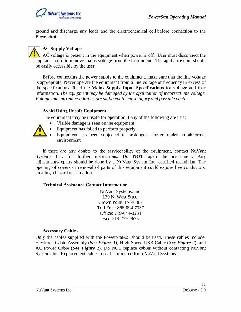
ground and discharge any leads and the electrochemical cell before connection to the PowerStat.
AC Supply Voltage AC voltage is present in the equipment when power is off. User must disconnect the
appliance cord to remove mains voltage from the instrument. The appliance cord should be easily accessible by the user.
Before connecting the power supply to the equipment, make sure that the line voltage
is appropriate. Never operate the equipment from a line voltage or frequency in excess of the specifications. Read the Mains Supply Input Specifications for voltage and fuse information. The equipment may be damaged by the application of incorrect line voltage. Voltage and current conditions are sufficient to cause injury and possible death.
Avoid Using Unsafe Equipment The equipment may be unsafe for operation if any of the following are true:
• Visible damage is seen on the equipment • Equipment has failed to perform properly • Equipment has been subjected to prolonged storage under an abnormal
environment
If there are any doubts to the serviceability of the equipment, contact NuVant Systems Inc. for further instructions. Do NOT open the instrument. Any adjustments/repairs should be done by a NuVant System Inc. certified technician. The opening of covers or removal of parts of this equipment could expose live conductors, creating a hazardous situation.
Technical Assistance Contact Information
NuVant Systems, Inc. 130 N. West Street
Crown Point, IN 46307 Toll Free: 866-894-7337
Office: 219-644-3231 Fax: 219-779-9675
Accessory Cables
Only the cables supplied with the PowerStat-05 should be used. These cables include: Electrode Cable Assembly (See Figure 1), High Speed USB Cable (See Figure 2), and AC Power Cable (See Figure 2). Do NOT replace cables without contacting NuVant Systems Inc. Replacement cables must be procured from NuVant Systems.

PowerStat Operating Manual
12 NuVant Systems Inc. Release - 3.0
MECHANICAL SPECIFICATIONS AND HANDLING
Overall Dimensions and Weight PowerStat overall dimensions
• 19 in. wide / 48.26 cm • 7.5 in. tall / 19.05 cm • 22 in. deep / 55.88 cm including handles
PowerStat overall weight
• 50 lbs. / 22.68 kg
Placement and Surroundings of the PowerStat DO NOT place the instrument in a location where the user can not access the
appliance cord. Place the instrument in a location where the appliance cord can be easily disconnected by the user.
The PowerStat should be placed on a flat clean surface that can support the weight of the instrument (50 lbs.). At least, 2 inches of space must be available at the rear to allow the flow of air. At least, 3 inches of space must be available on both sides to allow the flow of air. Obstructed airflow can lead to instrument malfunction over time. At no time should there be obstructions in front of the instrument. The user needs access to the controls and electrode cables located in front of the PowerStat.
The PowerStat comes equipped with carrying handles. Use both handles to carry the
instrument. You may also firmly grasp both sides of the instrument to position it in a desired location. Do not place any objects on top of the PowerStat.
ENVIRONMENTAL CONDITIONS
Normal Environmental Conditions for PowerStat The PowerStat is designed to operate indoors, in a laboratory environment. Do not
operate the instrument outdoors, as this may place the user in a hazardous situation due to unknown environmental conditions. Outdoor use of the instrument may cause a failure of operation due to environmental conditions. The PowerStat is rated to operate at an altitude of up to 6562 feet, or 2000 meters. The ambient temperature for operation is between 41 degrees Fahrenheit /5 degrees Celsius and 104 degrees Fahrenheit / 40 degrees Celsius.
Indoor use only Operate between 41° F ~ 104° F / 5° C ~ 40° C Altitude of no more than 6562 FT / 2000 M Humidity of up to 80% Pollution degree 2

PowerStat Operating Manual
13 NuVant Systems Inc. Release - 3.0
Instrument operation outside of these conditions will reduce instrument lifetime.
Although the Main supply voltage can fluctuate with load conditions, the PowerStat will continue to operate properly if these fluctuations do not exceed ± 10% of the specified instrument supply voltage. Main supply voltage setting on the PowerStat has a specified range itself for that particular setting. ± 10% applies to the upper and lower limits of that setting. The main supply voltage frequency for operation is 50Hz to 60Hz.
HARDWARE AND SOFTWARE CONVENTIONS
Hardware Conventions o Physical switches and connectors on the front panel relevant to operation
are designated as Bold Blue text. For example, Main Power Switch and Cell Enable Switch.
o Physical switches and connectors on the back panel relevant to operation are designated as Bold Red text. For example, AC Main Power Switch and Data Communication Port.
Software Naming Conventions o Software windows (screens) are designated as Window Name. For
example powerstat-05 Start Screen. o Within a Software Window, tabs are designated as Window Name / Tab
Name. For example powerstat-05 Recipe Editor / Range Selection. o Software buttons and switches are designated as [Object Name]. For
example [Delete current step]. o Entry fields are designated as Entry Field. Examples include Control
Type, Cell Disable After Procedure and Logging Duration(s). Items selected or typed in an Entry Field are designated "Selection or Entry".
o Software status indicators are presented in Bold Green. For example, Step OK?
HARDWARE INSTALLATION
Description of Controls and Connections This section provides a general description of the controls and indicators on the
PowerStat front and back panels. PowerStat Front Panel Figure 1 shows the PowerStat front panel and cable assembly.

PowerStat Operating Manual
14 NuVant Systems Inc. Release - 3.0
Figure 1 PowerStat Front Panel
1. Counter, Working and Reference Electrode Cable Assembly – The system allows current flow between the counter (Red) and working (Black) electrodes at a controlled current or potential. When under potential control, the applied potential is measured between the working and the reference (White) electrodes. The reference lead may be connected to an internal reference electrode. If no reference electrode is used, the reference lead must be connected to the counter electrode lead. For operation as a potentiostat or galvanostat all three leads must be properly connected. The PowerStat must be used with the cables provided. 2. Main Power Switch – This switch is used to turn the PowerStat system on or off. Pressing this switch on will allow the main AC voltage to be applied to the transformers of the power supplies. Pressing this switch to the off position will disconnect the AC voltage from the transformers of the power supplies. This switch lights green when on. 3. Cell Enable Switch – Places the test device in series with the potential follower board. Also acts as a safety feature, wherein the device is isolated from the current flow when the switch is in the off position. In the off position potential will still be measured but not controlled. When this switch is depressed AND the cell is enabled in the software this switch will illuminate blue. When the software control program is exited, this switch will not be illuminated even when depressed because exiting the software control program disables the cell automatically. 4. External Input – A standard BNC connector allows connection to an external signal source. Signals of up to ± 10 volts can be applied to this connection. The input impedance is 47K Ohms. 5. Electrode Connector – Attach the electrode cable assembly to this connector. This connector is a twist-lock type with the addition of a “keyed” connection. The electrode cable can be installed in only one way, thus ensuring the safest cable installation.
Caution: Make sure the Cell Enable switch is in the Disabled position before installing the Electrode cable.
1 2 3
4
5
PowerStat Operating Manual
15 NuVant Systems Inc. Release - 3.0
Procedure for Connection of Electrode Cables to an Electrochemical Device Electrodes should never be connected or disconnected from the PowerStat when the
cell is enabled. If the software is running, disable the cell using the software AND by putting the Cell Enable Switch in the out position, whether or not it is illuminated blue. For operator safety, and protection of the PowerStat electronics, always connect and disconnect electrodes in the following order (NOTE: counter, reference, working sense (if available), and working electrodes must ALL be connected to the electrochemical device. In a typical 3-electrode system the working sense is shorted to the working electrode):
1) Electrode connection; a) With the cell disabled connect the White Reference electrode lead; b) With the cell disabled connect the Red Counter electrode lead; c) With the cell disabled connect the Black Working electrode lead. 2) Electrode disconnection; a) With the cell disabled disconnect the Black Working electrode lead; b) With the cell disabled disconnect the Red Counter electrode lead; c) With the cell disabled disconnect the White Reference electrode lead; d) Do not enable the cell unless all three electrodes are connected correctly.

PowerStat Operating Manual
16 NuVant Systems Inc. Release - 3.0
PowerStat Back Panel
Figure 2 PowerStat Back Panel
1. AC Power Input – 8 A at 250 VAC Slow blow fuse for voltage selections of 115/127VAC or 4 A at 250 VAC Slow blow fuse for voltage selection of 230 VAC 50~60Hz. Use only the supplied power cable to run this instrument. Contact NuVant systems if a replacement is needed. 2. Main Power Voltage Selector Switch and AC Fuse Holder – External AC fuse holder. 8 A at 250 VAC Slow blow fuse for voltage selections of 115/127VAC or 4 A at 250 VAC Slow blow fuse for voltage selection of 230 VAC 50~60Hz. 3. AC Main Power Switch – AC main power switch. This must be on for the front panel Main Power Switch to illuminate. 4. Data Communication Port – The data acquisition (DAQ) port communicates with a computer using a USB cable. Use only the cable provided by NuVant.
1
2
3
4
5
6
7 8

PowerStat Operating Manual
17 NuVant Systems Inc. Release - 3.0
5. Serial Number Plate – Removal of or defacing the serial number plate will void the warranty. 6. Cooling Fan – Allow at least 2 inches of space behind and to the sides of the cooling fans. Periodically inspect the fan ports to make sure debris does not obstruct air flow. 7. AC Power Cable – The power cable must be plugged firmly into the back of the instrument. The other end of the power cable must be plugged into a grounded circuit of the correct polarity and voltage. The voltages are: 115/127VAC or 230VAC 50~60Hz. Have a certified electrician verify the earth grounding of the wall outlet. Do not replace this cable with any other similar cable. This power cable supplied is rated for the instrument. 8. USB Data Communication Cable – Do not connect this cable to the computer until the software is installed. Ensure this cable is inserted completely into the instrument and computer during use. Do not connect a USB extension cable to this cable. Do not replace this cable without contacting NuVant Systems to obtain an appropriate cable.
CLEANING AND MAINTENANCE The PowerStat requires minimal maintenance. The instrument must be clean and free of oil, dust and debris. If a buildup occurs, unplug the instrument from the mains AC Power Input. Use a soft cloth to wipe the instrument clean. If necessary, use a small amount of soap and water on the cloth to remove deposits. Make sure all the switches, connectors and fan ports are clean. A small brush can be used to clean the fan ports. Check the fan ports regularly for buildup. If there is visible damage, worn electrode cables or power cable, do NOT operate the instrument. Contact NuVant for replacement cables or for return of instrument for repair.
SERVICE AND REPAIR
ONLY NuVant is authorized to service and repair the PowerStat-05. ONLY NuVant staff should open the chassis or remove instrument components. ONLY NuVant Systems can verify safe operation of the instrument after a repair. If there are doubts about instrument functionality, contact NuVant at (219) 644-3231.
PowerStat Operating Manual
18 NuVant Systems Inc. Release - 3.0
SOFTWARE INSTALLATION AND OPERATION
Software Installation: The PowerWare installation DVD includes the LabVIEW Runtime Engine, the NI-DAQmx driver, the NI-Serial driver and the PowerWare software. Version specific installation instructions are provided with each PowerWare installation DVD. Read the instructions before installing the software and connecting hardware. Install the software before connecting the hardware to enable recognition by Windows and the National Instruments “New Hardware Wizard 1.0 Install the LabVIEW Runtime Engine using the default installation options. Restart
the computer after installation is complete. 2.0 Install NI-DAQmx with the default installation options. Restart the computer after
installation is complete. 3.0 If the temperature and/or mass flow controller options are ordered, the NI-Serial
driver on the installation DVD must also be installed. Installation and COM port configuration instructions are provided under separate cover if these options are ordered.
4.0 Install the PowerWare software. A re-boot is not required after installing the PowerWare software.
5.0 Connect the USB Data Communications Cable to the PowerStat back panel. Do not plug it into the computer yet.
6.0 Ensure that the front panel Cell Enable Switch is in the out (off) position. Turn on the rear panel AC Main Power Switch. Press the front panel Main Power Switch to turn on the PowerStat. The Main Power Switch should illuminate green and you should hear the sound of the cooling fan.
7.0 Connect the USB Data Communications Cable to the computer and wait to see the new hardware installed twice. The hardware must be recognized first by Windows and then by the National Instruments Measurement & Automation Explorer (MAX).
NuVant provides periodic software upgrades to ensure that instruments are working at the highest efficiency. Current versions of the PowerWare software are available through www.nuvant.com. Contact NuVant for additional information if necessary. The NI-DAQmx driver and LabVIEW Runtime Engine may be downloaded from the National Instruments website www.ni.com or through the following sites: LabVIEW 2011 Runtime Engine: http://joule.ni.com/nidu/cds/view/p/id/2534/lang/en NI-DAQmx v9.4 Driver: http://joule.ni.com/nidu/cds/view/p/id/2604/lang/en

PowerStat Operating Manual
19 NuVant Systems Inc. Release - 3.0
ON BOARD FUNCTION GENERATOR VS CPU TIMING
The use of the CPU for real time construction of multistep wave forms provides versatility. However, use of the CPU also comes with some risk in affecting clock speed. If non-essential applications are running simultaneously with PowerWare (including PowerWare Real Time Graphics), the clock speed will be adversely affected. When using the CPU for potential programming, the maximum timing accuracy is attained when only PowerWare is running (without real time graphics). Clearing the caches by rebooting the computer may add to the timing accuracy.
When using the onboard function generator, there are no measurable timing issues. Thus the onboard function generator should be used rather than the CPU whenever possible.

PowerStat Operating Manual
20 NuVant Systems Inc. Release - 3.0
Operation of Control and Data Acquisition Software Note: Disabling any screen saver is recommended when the software is running. This enables continuous visual monitoring of the system and ensures proper instrument functionality in the initial stages of testing. Make certain the PowerStat in on and the USB cable is connected to the PC before starting the PowerWare software.
1.1.1. powerstat-05 Start Screen 1. Go to StartAll Programs PowerWare-## v#.#.##.#### PowerWare-## to
run the PowerWare software.
Figure 3 Location of Software
PowerStat Operating Manual
21 NuVant Systems Inc. Release - 3.0
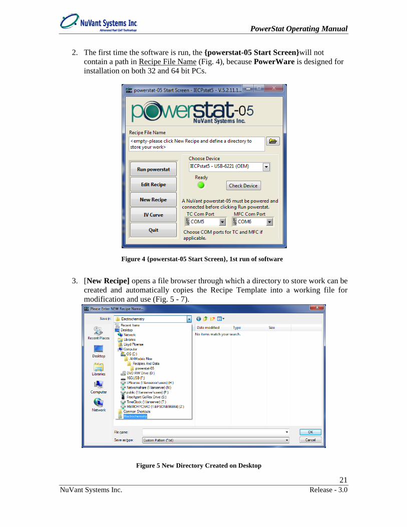
2. The first time the software is run, the powerstat-05 Start Screenwill not contain a path in Recipe File Name (Fig. 4), because PowerWare is designed for installation on both 32 and 64 bit PCs.
3. [New Recipe] opens a file browser through which a directory to store work can be
created and automatically copies the Recipe Template into a working file for modification and use (Fig. 5 - 7).
Figure 4 powerstat-05 Start Screen, 1st run of software
Figure 5 New Directory Created on Desktop

PowerStat Operating Manual
22 NuVant Systems Inc. Release - 3.0
Once the path is established, PowerWare will remember the last path and Recipe loaded into powerstat-05 Start Screen.
4. Established Recipe files are loaded from the powerstat-05 Start Screen by clicking to the right of Recipe File Name.
Figure 7 Recipe File Name with an established path.
Figure 6 Recipe Naming
PowerStat Operating Manual
23 NuVant Systems Inc. Release - 3.0
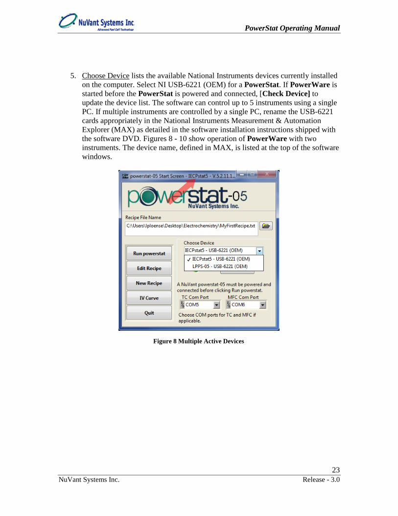
5. Choose Device lists the available National Instruments devices currently installed on the computer. Select NI USB-6221 (OEM) for a PowerStat. If PowerWare is started before the PowerStat is powered and connected, [Check Device] to update the device list. The software can control up to 5 instruments using a single PC. If multiple instruments are controlled by a single PC, rename the USB-6221 cards appropriately in the National Instruments Measurement & Automation Explorer (MAX) as detailed in the software installation instructions shipped with the software DVD. Figures 8 - 10 show operation of PowerWare with two instruments. The device name, defined in MAX, is listed at the top of the software windows.
Figure 8 Multiple Active Devices

PowerStat Operating Manual
24 NuVant Systems Inc. Release - 3.0
Open PowerWare again. Use Choose Device to select the other PowerStat.
6. [Run powerstat] from the powerstat-05 Start Screen loads the Recipe file listed in Recipe File Name into Run powerstat. The Recipe file does not start automatically when [Run powerstat] is pressed. Figure 10 shows Run powerstat windows for the two instruments.
Figure 9 powerstat-05 Start Screen For Two Instruments on the Same PC

PowerStat Operating Manual
25 NuVant Systems Inc. Release - 3.0
7. [Edit Recipe] from the powerstat-05 Start Screen shows powerstat-05
Recipe Editor, which allows viewing and editing of the Recipe file listed in powerstat-05 Start Screen Recipe File Name.
8. [New Recipe] creates a new Recipe file from the Recipe Template. The path to the new Recipe automatically loads into Recipe File Name. This recipe must be opened using the powerstat-05 Recipe Editor and adjusted as necessary.
9. [IV Curve] from powerstat-05 Start Screen opens the IV Curve window to
view and analyze acquired IV data.
10. [Quit], on the powerstat-05 Start Screen, closes all other running windows and exits PowerWare software. If [Quit] is pressed when Run powerstat is open, the cell will automatically disable and the DAQ card reset as powerstat-05 Start Screencloses.
1.1.2. Recipe Editor [Edit Recipe] from the powerstat-05 Start Screen opens powerstat-05 Recipe Editor (Fig. 11). The powerstat-05 Recipe Editor allows change of Recipe file parameters. The powerstat-05 Recipe Editor does not provide direct control of the instrument. Features of the powerstat-05 Recipe Editor are described below:
Figure 10 Run powerstat Windows for Two Simultaneous Instruments

PowerStat Operating Manual
26 NuVant Systems Inc. Release - 3.0
1. Recipe files may also be loaded through File → Open on the menu bar. Files
loaded through the powerstat-05 Recipe Editor menu bar do not automatically load into the powerstat-05 Start Screen Recipe File Name control.
2. The entire Recipe is displayed in the Recipe Step Table. The active step in the
Recipe Step Table is highlighted with a blue border and also appears at the lower right hand corner. Only the active step can be edited. Users can enter experimental parameter values for the selected (active) step in the Entry fields above the Recipe Step Table.
3. Use the button controls (Fig. 12) under the menu bar to navigate between steps.
Pausing the mouse over these buttons will display 'bubble help':
Figure 11 powerstat-05 Recipe Editor with Unedited New Recipe Loaded
Menu Bar
PowerStat Operating Manual
27 NuVant Systems Inc. Release - 3.0
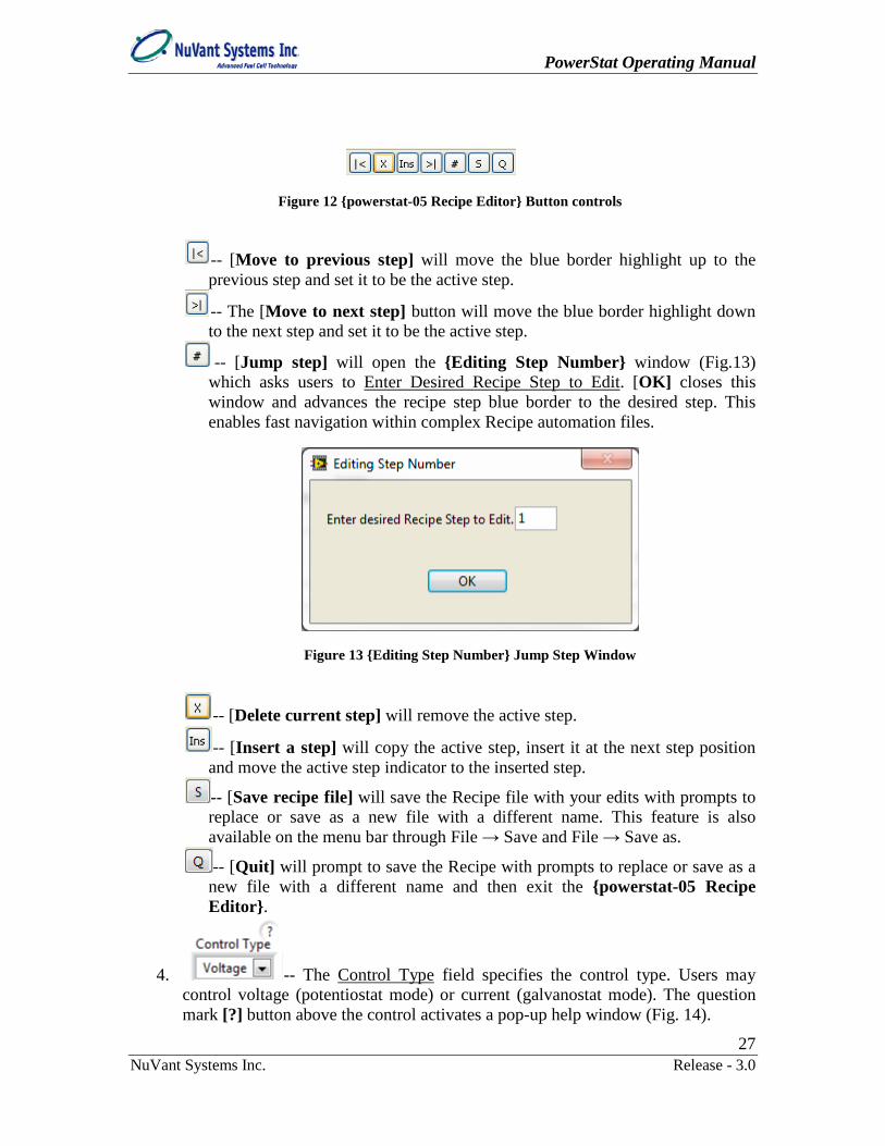
-- [Move to previous step] will move the blue border highlight up to the previous step and set it to be the active step.
-- The [Move to next step] button will move the blue border highlight down to the next step and set it to be the active step.
-- [Jump step] will open the Editing Step Number window (Fig.13) which asks users to Enter Desired Recipe Step to Edit. [OK] closes this window and advances the recipe step blue border to the desired step. This enables fast navigation within complex Recipe automation files.
-- [Delete current step] will remove the active step.
-- [Insert a step] will copy the active step, insert it at the next step position and move the active step indicator to the inserted step.
-- [Save recipe file] will save the Recipe file with your edits with prompts to replace or save as a new file with a different name. This feature is also available on the menu bar through File → Save and File → Save as.
-- [Quit] will prompt to save the Recipe with prompts to replace or save as a new file with a different name and then exit the powerstat-05 Recipe Editor.
4. -- The Control Type field specifies the control type. Users may control voltage (potentiostat mode) or current (galvanostat mode). The question mark [?] button above the control activates a pop-up help window (Fig. 14).
Figure 12 powerstat-05 Recipe Editor Button controls
Figure 13 Editing Step Number Jump Step Window

PowerStat Operating Manual
28 NuVant Systems Inc. Release - 3.0
5. -- The Signal Type (Ramp/Soak) selection field allows the user to specify the operation performed during the step. The list of operations include: "Ramp to", "Soak at", "OCV", "CV Scan", "Potential Step", "Pulse Voltammetry" and "Polarization Resistance". Ramp and Soak Signal Types work with both the Voltage and Current control types. A maximum of one million points can be acquired in CV Scan, Potential Step, and Pulse Voltammetry operations. The question mark [?] button above the control activates a pop up help window (Fig. 15).
a. Soak
Figure 14 ? Control Type Pop Up Help Window
Figure 15 ? Signal Type Pop Up Help Window

PowerStat Operating Manual
29 NuVant Systems Inc. Release - 3.0
Constant Voltage (Potentiostat) Example.
Figure 16 Constant Voltage (Potentiostat) Example Entry Field Item Numbers
Item 1: Set the Control Type to “Voltage”. Item 2: Set the Signal Type (Ramp/Soak) to “Soak at”. Item 3: Enter the desired voltage into Set/Final Potential (V). Item 4: For dimensions of current density, enter the electrode area into Electrode Area (cm2). The number cannot be zero. Once entered, the area does not need to be re-entered in every step. Item 5: By default all new Recipes will disable the cell upon completion of a Recipe. If this is not desired, uncheck [Cell Disable After Procedure]. This does not need to be re-entered in every step. Item 6: To go to a fixed potential after completion of a Recipe, enter the potential into Standby Potential (V). However, if Cell Disable After Procedure is checked, the Standby Potential (V) will not be applied because the cell is at open circuit. This does not need to be entered in every step. This can be changed during operation in the Run powerstatWindow without changing the Recipe. Reloading the Recipe in Run powerstat will restore the previous Standby Potential (V) value unless modifications are saved to the Recipe. Item 7: Enter the Logging Duration(s) (sample recording interval) in seconds. This time must be ≥ 0.1 s for a Soak at step. The step will be faulty and the Step OK? (Item 8) will be red if the Total Duration of Current Step (Item 9) is not an integer multiple of Logging Duration(s). Item 8: If the Step OK? indicator light is green, the step is executable. If the Step OK? indicator light is red, the step is not executable because of timing entry errors.
5
1 2 3
4
6
7
8 9
PowerStat Operating Manual
30 NuVant Systems Inc. Release - 3.0
Item 9: Enter the time desired for the soak step into Total Duration of Current Step. This time must be an integer multiple of the Logging Duration(s) for the step to be executable. Save your changes. Note: Items discussed in previous sections will not be re-iterated. For example, there is no need to mention Cell Disable After Procedure or Step OK? in every section. Constant Current (Galvanostat) Example, Time Based Only.
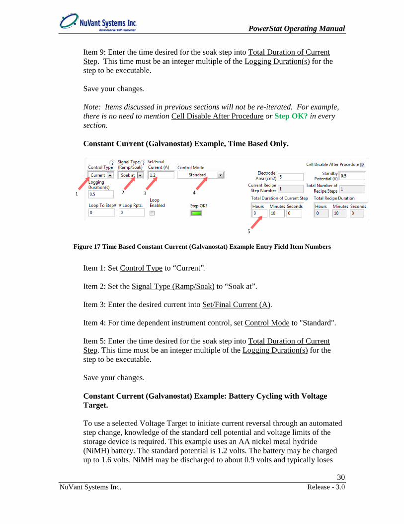
Figure 17 Time Based Constant Current (Galvanostat) Example Entry Field Item Numbers
Item 1: Set Control Type to “Current”. Item 2: Set the Signal Type (Ramp/Soak) to “Soak at”. Item 3: Enter the desired current into Set/Final Current (A). Item 4: For time dependent instrument control, set Control Mode to "Standard". Item 5: Enter the time desired for the soak step into Total Duration of Current Step. This time must be an integer multiple of the Logging Duration(s) for the step to be executable. Save your changes. Constant Current (Galvanostat) Example: Battery Cycling with Voltage Target. To use a selected Voltage Target to initiate current reversal through an automated step change, knowledge of the standard cell potential and voltage limits of the storage device is required. This example uses an AA nickel metal hydride (NiMH) battery. The standard potential is 1.2 volts. The battery may be charged up to 1.6 volts. NiMH may be discharged to about 0.9 volts and typically loses
1 2 3 4
5

PowerStat Operating Manual
31 NuVant Systems Inc. Release - 3.0
2% of charge per day. The mAHr rating of the NiMH battery is about 1,000 mAHr. The positive terminal of the battery is connected to the Working electrode and both the Counter and Reference electrodes are connected to the negative battery terminal. Step 1: Create an Open Circuit step as the first step. Use the standard potential of the battery, here "1.2 V", as the Standby Potential (V).
Figure 18 Galvanostat Battery Cycling with Voltage Target Control, Showing Example OCV Step
Entry Fields.
Item 1: Control Type is “Voltage”. Item 2: Signal Type (Ramp/Soak) is “OCV”. Item 3: Standby Potential (V) is set to standard potential of the storage device, in this case “1.2” V. This prevents inadvertent short circuiting.
1 2
3
4 5

PowerStat Operating Manual
32 NuVant Systems Inc. Release - 3.0
Item 4: Enter a value appropriate for the internal capacitance of the cell into Total Duration of Current Step. This might be 5 times the product of the capacitance and resistance of the cell (5RC). In this case “0” “1” “0” are entered for 1 minute. Save your Recipe. Step 2: Fig. 19 shows the Battery.txt recipe loaded into the powerstat-05 Start Screen Recipe File Name. [Run powerstat] opens Run powerstat (Fig. 20) with the Recipe from the powerstat-05 Start Screen Recipe File Name loaded. The [START] in Run powerstat executes a Recipe. When Run powerstat is open, the PowerStat-05 is waiting for either manual mode commands or [START].
Figure 19 Selecting a Recipe to Run From the powerstat-05 Start Screen

PowerStat Operating Manual
33 NuVant Systems Inc. Release - 3.0
Figure 20 Observing the Open Circuit Potential of a Cell
With the instrument at open circuit observe the open circuit voltage (OCV) in the Cell Voltage (V) indicator field at the top of the window. The 1.26 V OCV observed here is larger than the 1.2 V standard potential of a NiMH battery. [Quit] to exit Run powerstat. Step 3: Return to powerstat-05 Recipe Editor and insert an OCV step using
(Fig. 21 - 22). Edit the step to discharge the battery to 1.1 V at 0.5 Amps. With the electrode connections and battery in this example, discharging entails setting the direction of the current negative (-0.5 A).
This is the measured Open Circuit Voltage

PowerStat Operating Manual
34 NuVant Systems Inc. Release - 3.0
Figure 21 Duplicate Step Creation - Click

PowerStat Operating Manual
35 NuVant Systems Inc. Release - 3.0
Figure 22 Duplicate Step Completed

PowerStat Operating Manual
36 NuVant Systems Inc. Release - 3.0
Figure 23 Voltage Target Constant Current Example Discharge Step Entry Field Item Numbers
Editing for a discharge step. Item 1: Set Control Type to "Current". Item 2: Set Signal Type (Ramp/Soak) to "Soak at". Item 3: Enter “-0.5” to Set/Final Current (A). Item 4: Set Control Mode to "Battery". Item 5: Enter the Battery Voltage Target (V), here "1.1" V. Item 6: Set the Comparator Mode to end the step when the voltage is "< or = V" where V is the Battery Voltage Target (V). Item 7: Enter a Step Description.
1 2
8 7
4 5
3
6

PowerStat Operating Manual
37 NuVant Systems Inc. Release - 3.0
Item 8: The Total Duration of Current Step entry field is not visible. This is because the Battery Voltage Target (V) provides feedback control, with the time for current reversal determined only by the state of the battery. Nevertheless, the time place holder cannot be zero. Click on the powerstat Recipe Editor / V or I vs. t Graph, then [Show graph] (Fig. 24). A Control Mode of "Battery" automatically enters 1 second for this Voltage Target control step. The actual times will be recorded in the data file.
Figure 24 powerstat-05 Recipe Editor / I vs. t Graph View of Voltage Target Constant Current
Example OCV and Discharge Steps
Step 4: In the powerstat-05 Recipe Editor / Recipe Table, go to the second and
last step. Click on the twice to create two more steps. Go back to step 3 and change this to an OCV step with the same duration as OCV step 1. Then, go to step 4 and edit this to create a charging step.

PowerStat Operating Manual
38 NuVant Systems Inc. Release - 3.0
Figure 25 Voltage Target Constant Current Example Charge Step Entry Field Item Numbers
Editing for a charging step. Item 1: Control Type is “Current”. Item 2: Signal Type (Ramp/Soak) is “Soak at”. Item 3: Enter the current "0.5" into Set/Final Current (A). Since this is a charge step the current is positive "0.5" A. Item 4: Control Mode is “Battery”. Item 5: Enter the Battery Voltage Target (V), here "1.4" V. Item 6: Set the appropriate Comparator Mode. During charging, the potential increases with time. End this step when the voltage is greater than or equal to V
1 2
7
4 5
3
6

PowerStat Operating Manual
39 NuVant Systems Inc. Release - 3.0
where V is the Battery Voltage Target (V). Therefore, the appropriate Comparator Mode is "> or = V". Item 7: Enter a Step Description. Save your Recipe. The graph should appear as in Fig. 26.
Figure 26 I vs. t Graph View of Voltage Target Constant Current Example OCV, Discharge and
Charge Steps
Step 5: If desired, create a loop of the entire cycle for long term battery performance testing. Note: More than one loop can exist in a recipe but loops cannot be embedded.

PowerStat Operating Manual
40 NuVant Systems Inc. Release - 3.0
Figure 27 Voltage Target Constant Current Example Loop Creation Field Item Numbers
Item 1: While at the last step of loop creation (here step #4), enter the step # to loop back to (here step #"1") into Loop To Step #. Item 2: Enter the desired number of loops, here "3", into # Loop Rpts. Item 3: Activate looping by placing a "check mark" in Loop Enabled. Save your Recipe. The looped Recipe graph should look like Fig. 28.
1 2 3

PowerStat Operating Manual
41 NuVant Systems Inc. Release - 3.0
Figure 28 I vs. t Graph View of Voltage Target Constant Current Example with Looped OCV,
Discharge and Charge Steps
Step 6: Make sure the recipe (path) is loaded into powerstat-05 Start Screen Recipe File Name. Click [Run powerstat].

PowerStat Operating Manual
42 NuVant Systems Inc. Release - 3.0
Figure 29 Voltage Target Constant Current Example Run powerstat Item Numbers 1-2
Item 1: The Recipe loads here in powerstat-05 Start Screen. Other Recipes may be loaded here using the folder icon to the right of Recipe file. In addition, if edits are made with the powerstat-05 Recipe Editor to the file loaded here, the edits are loaded with [Reload]. Item 2: Click Run powerstat / V vs. t Graph.
Figure 30 Voltage Target Constant Current Example Run Screen Item Numbers 3-5
1
2
3
4
5

PowerStat Operating Manual
43 NuVant Systems Inc. Release - 3.0
Item 3: Set the Seconds/Sample to the length of the minimum Logging Duration(s) in your recipe, here "1". This conserves video RAM and minimizes video updates. Item 4: [Clear Chart] to remove existing display. Item 5: Click Run powerstat / Battery Curve.
Figure 31 Voltage Target Constant Current Example Run Screen Item Numbers 6-8
Item 6: [Clear Chart] to remove old data display. Item 7: [Turn Plot On] to show the Voltage vs. mAHr data during Recipe automation. This graph will only populate during Galvanostat soak Recipes that have Voltage Target or Voltage Cut Off feedback control. Item 8: The Status Field indicates that the Recipe is already running. The [START] was pressed to put some data into the graphs. Go to Run powerstat / Recipe.
6
8
7
8
PowerStat Operating Manual
44 NuVant Systems Inc. Release - 3.0
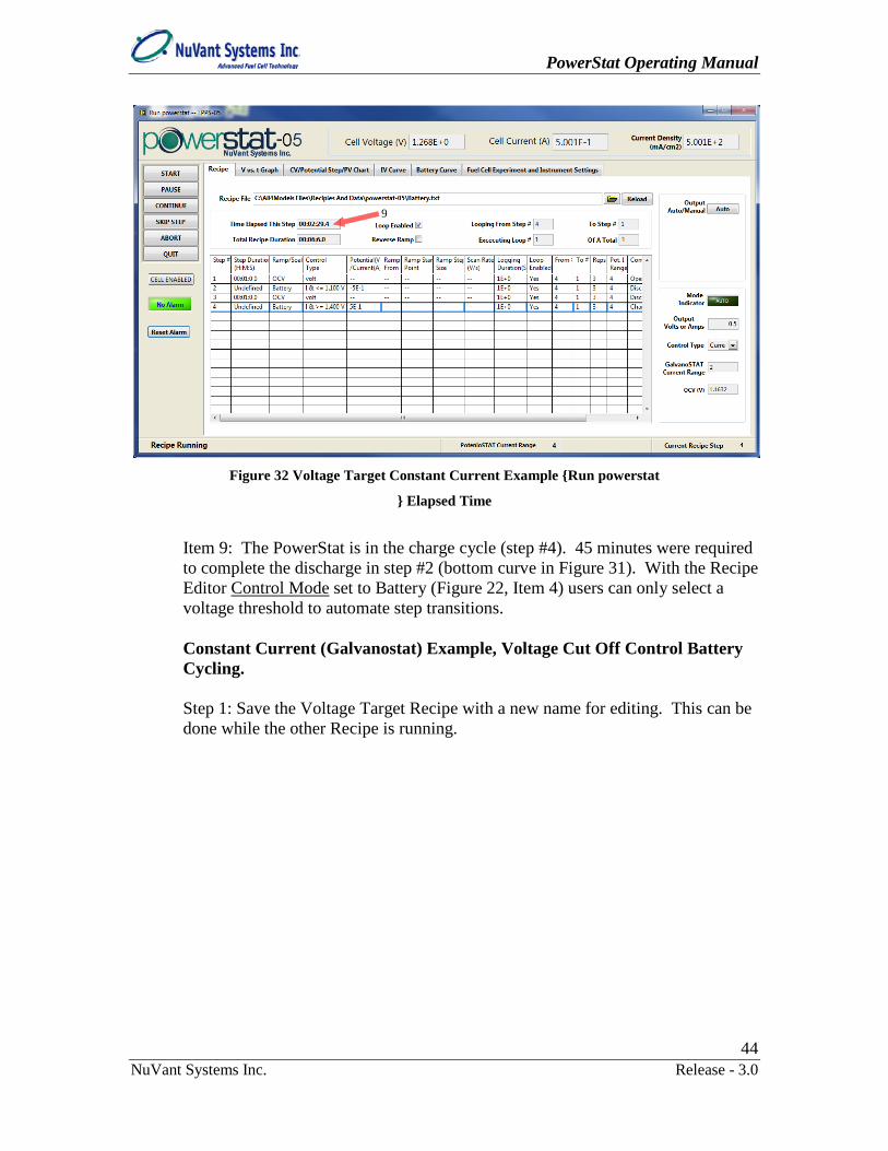
Figure 32 Voltage Target Constant Current Example Run powerstat
Elapsed Time
Item 9: The PowerStat is in the charge cycle (step #4). 45 minutes were required to complete the discharge in step #2 (bottom curve in Figure 31). With the Recipe Editor Control Mode set to Battery (Figure 22, Item 4) users can only select a voltage threshold to automate step transitions. Constant Current (Galvanostat) Example, Voltage Cut Off Control Battery Cycling. Step 1: Save the Voltage Target Recipe with a new name for editing. This can be done while the other Recipe is running.
9

PowerStat Operating Manual
45 NuVant Systems Inc. Release - 3.0
Figure 33 Saving a Recipe With Another Name
Item 1: From the menu bar File → Save as to a new name following the prompts. The renamed Recipe is now loaded in the powerstat-05 Recipe Editor, not in the powerstat-05 Start Screen Recipe File Name. This is okay because Recipes can be loaded into Run powerstat directly. Go to the first current control soak step #2.
1
PowerStat Operating Manual
46 NuVant Systems Inc. Release - 3.0
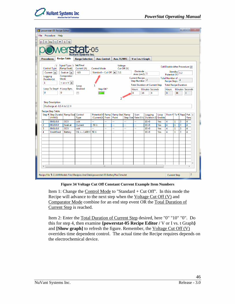
Figure 34 Voltage Cut Off Constant Current Example Item Numbers
Item 1: Change the Control Mode to "Standard + Cut Off". In this mode the Recipe will advance to the next step when the Voltage Cut Off (V) and Comparator Mode combine for an end step event OR the Total Duration of Current Step is reached. Item 2: Enter the Total Duration of Current Step desired, here "0" "10" "0". Do this for step 4, then examine powerstat-05 Recipe Editor / V or I vs. t Graph and [Show graph] to refresh the figure. Remember, the Voltage Cut Off (V) overrides time dependent control. The actual time the Recipe requires depends on the electrochemical device.
1
2

PowerStat Operating Manual
47 NuVant Systems Inc. Release - 3.0
Figure 35 Voltage Cut Off Current Example I vs. t Graph
The graph should look like Figure 43 with the override time used. In this example the override time is 600 seconds. Save your Recipe. Meanwhile, the other (Voltage Target feedback only) recipe is in the second loop and discharging.

PowerStat Operating Manual
48 NuVant Systems Inc. Release - 3.0
Figure 36 Battery Cycling: V vs. mAHr with Voltage Target, Looped, Second Discharge
This demonstrates how automation Recipes can be developed during data acquisition. Below is the Voltage Target Battery Curve following completion of all three loops.
Figure 37 Battery Cycling V vs. mAHr Graph with Voltage Target, Looped, Three Complete Cycles

PowerStat Operating Manual
49 NuVant Systems Inc. Release - 3.0
The graph of voltage and current vs. time for the Voltage Target test looks like this.
Figure 38 Battery Cycling I & V vs. t Graph with Voltage Target, Looped, Three Complete Cycles
b. Ramp
Figure 39 Ramp Signal Type
If the Signal type is set to "Ramp to", and Ramp From control is set to "E prev."
the potential will rise (or fall) from the last step's final set point to the
Set/Final Potential (V) entered in the field.

PowerStat Operating Manual
50 NuVant Systems Inc. Release - 3.0
If the Ramp From control is set to "E ref." , the potential will rise (or
fall) from the Initial Ramp Potential (V) entered in to the Set/Final
Potential (V) entered in the field.
If Ramp From is set to "OCV" the ramp will begin from a measured and saved open circuit voltage or in the case of current (galvanostat) mode a current value of zero. An open circuit step must be programmed in the previous step for the software to record an OCV value.
Users can also check the Reverse Ramp box to run a reverse ramp from the final value back to the initial value. The ramp slope controls are Step Size (V) and Scan Rate (V/s),
, and are used to create a discrete staircase for the ramp. During the ramp operation, the program will record the last data point of each discrete staircase stage comprising the ramp. The value of the step duration in a ramp must be greater than or equal to 0.1s. If faster scan rate are required, select "CV Scan" as the Signal Type (Ramp/Soak). The step duration is defined as:
Step Size (V)Scan Rate (V s⁄ )
c. OCV
Figure 40 OCV (Open Circuit Voltage) Signal Type
The Signal Type (Ramp/Soak) "OCV" setting will place the cell at open circuit for a time period specified in Total Duration of Current Step while measuring the cell potential at intervals specified in Logging Duration(s).

PowerStat Operating Manual
51 NuVant Systems Inc. Release - 3.0
d. CV Scan
Figure 41 CV Scan Signal Type
Signal Type (Ramp/Soak) "CV Scan" is similar to "Ramp to" but uses an onboard waveform generator to generate a linear or cyclic ramp operation. This enables faster scan rates. The maximum data acquisition rate is 39,999 data points per second. The scan rate is also limited by the hardware response frequency. Optimal acquisition rates are smaller than 20,000 Hz. The acquisition rate can be calculated as:
Scan Rate (V s⁄ )Step Size (V)
e. Potential Step
Figure 42 Potential Step Signal Type
Signal Type (Ramp Soak) "Potential Step" will hold Initial Potential (V) for a time period specified in Initial Potential Time (s), then change to Set/Final Potential (V), hold it for a time period specified in Final Potential Time (s). The Logging Duration(s) field specifies the data logging duration. The minimum value of logging duration in Signal Type (Ramp Soak) "Potential Step" is 0.1 ms. A "Potential Step" in which the initial and final potentials are the same may be used to create an effective "Soak at" step with very fast data acquisition rates. "Potential Step" is hardware timed and this produces excellent time resolution where necessary.
PowerStat Operating Manual
52 NuVant Systems Inc. Release - 3.0
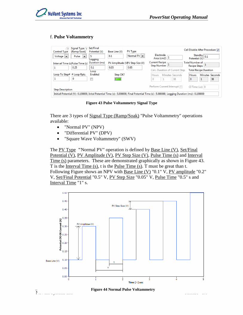
f. Pulse Voltammetry
Figure 43 Pulse Voltammetry Signal Type
There are 3 types of Signal Type (Ramp/Soak) "Pulse Voltammetry" operations available:
• "Normal PV" (NPV) • "Differential PV" (DPV) • "Square Wave Voltammetry" (SWV)
The PV Type "Normal PV" operation is defined by Base Line (V), Set/Final Potential (V), PV Amplitude (V), PV Step Size (V), Pulse Time (s) and Interval Time (s) parameters. These are demonstrated graphically as shown in Figure 43. T is the Interval Time (s), t is the Pulse Time (s). T must be great than t. Following Figure shows an NPV with Base Line (V) "0.1" V, PV amplitude "0.2" V, Set/Final Potential "0.5" V, PV Step Size "0.05" V, Pulse Time "0.5" s and Interval Time "1" s.
Figure 44 Normal Pulse Voltammetry
PowerStat Operating Manual
53 NuVant Systems Inc. Release - 3.0
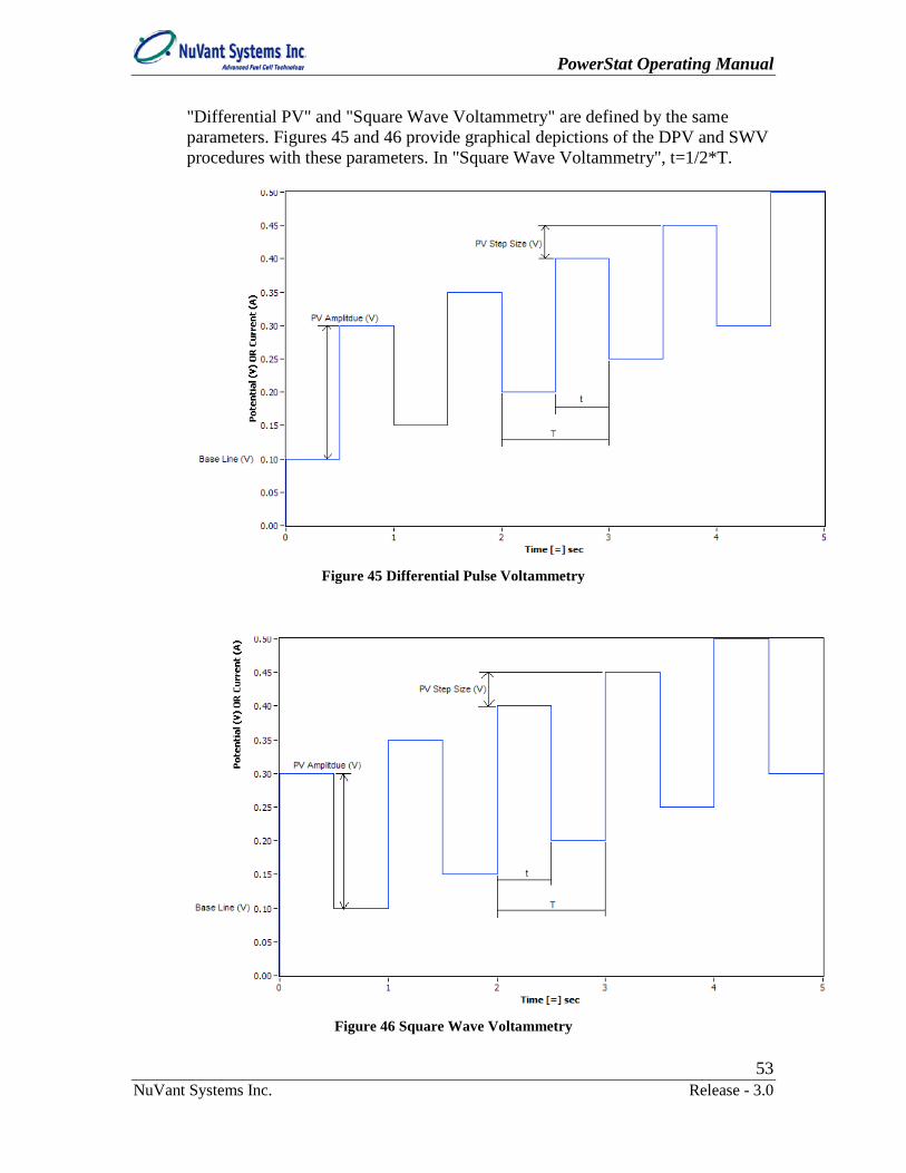
"Differential PV" and "Square Wave Voltammetry" are defined by the same parameters. Figures 45 and 46 provide graphical depictions of the DPV and SWV procedures with these parameters. In "Square Wave Voltammetry", t=1/2*T.
Figure 45 Differential Pulse Voltammetry
Figure 46 Square Wave Voltammetry

PowerStat Operating Manual
54 NuVant Systems Inc. Release - 3.0
The Logging Duration (mS) field specifies the data logging duration, the minimum value of the logging duration in "Pulse Voltammetry" is 0.1 ms.
6. The user can create loops in a recipe by checking in the last step of the desired loop. The Loop to Step# parameter is the first step of the desired loop. The #Loop Reps parameter is the number of repetitions in the loop
.
7. computes and displays the total running time of the entire recipe.
8. allows users to establish a potential set point that will be applied when recipe is not running or before the start of the recipe.
9. enables use of current density.
10. Check to disable the cell after recipe completion.
Recipe comments can be input in the Step Description box above the table.

PowerStat Operating Manual
55 NuVant Systems Inc. Release - 3.0
11. Predefined standard experiments are available in powerstat-05 Recipe Editor. These experiments are typically specific combinations of the recipe operations available in the powerstat-05 Recipe Editor / Recipe Table without requiring the programming of an entire sequence line-by-line. The powerstat-05 Recipe Editor menu bar item Procedure → Methods (Fig. 47) displays the available predefined standard experiments.
Figure 47 Predefined Standard Experiments

PowerStat Operating Manual
56 NuVant Systems Inc. Release - 3.0
Figure 48 Linear/Cyclic Voltammetry
Select Linear/Cyclic "Linear Voltammetry" uses a linear ramp from Start Voltage (V) to First Vertex Voltage (V). Step Potential defines the size of each discrete step. Select Linear/Cyclic "Cyclic Voltammetry" has a Second Vertex Voltage (V). Cyclic Voltammetry ramps from Start Voltage (V) to First Vertex Voltage
(V) then to Second Vertex Voltage. Check to use Start Voltage (V) value as the Second Vertex Voltage. Use Number of Scans to specify the number of times to repeat this scan. After ramp finishes, the PowerStat will
soak at Standby Voltage (V) or disable the cell if is checked. In Linear/Cyclic Voltammetry methods, when the time of each step (Step Potential/Scan Rate) is less than 1 second, the software will automatically choose the PowerStat onboard waveform generator to generate linear/cyclic ramp to
PowerStat Operating Manual
57 NuVant Systems Inc. Release - 3.0
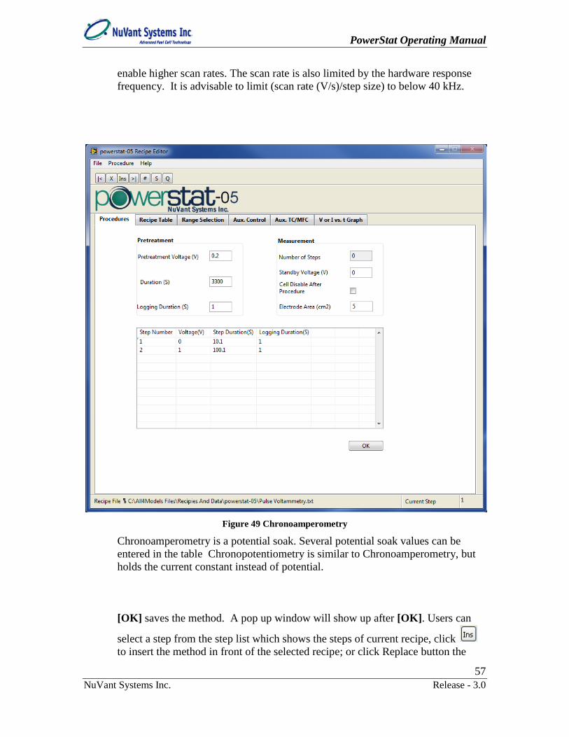
enable higher scan rates. The scan rate is also limited by the hardware response frequency. It is advisable to limit (scan rate (V/s)/step size) to below 40 kHz.
Figure 49 Chronoamperometry
Chronoamperometry is a potential soak. Several potential soak values can be entered in the table Chronopotentiometry is similar to Chronoamperometry, but holds the current constant instead of potential. [OK] saves the method. A pop up window will show up after [OK]. Users can
select a step from the step list which shows the steps of current recipe, click to insert the method in front of the selected recipe; or click Replace button the
PowerStat Operating Manual
58 NuVant Systems Inc. Release - 3.0
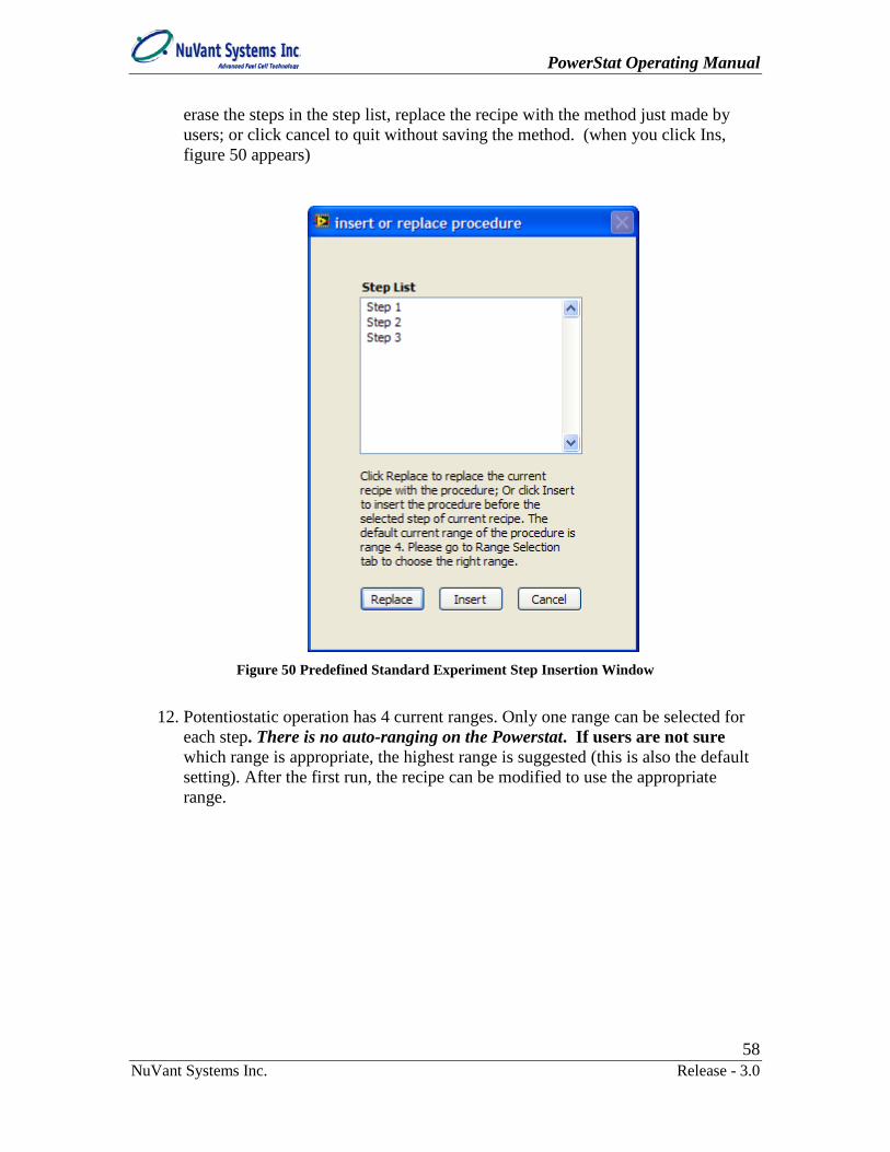
erase the steps in the step list, replace the recipe with the method just made by users; or click cancel to quit without saving the method. (when you click Ins, figure 50 appears)
Figure 50 Predefined Standard Experiment Step Insertion Window
12. Potentiostatic operation has 4 current ranges. Only one range can be selected for
each step. There is no auto-ranging on the Powerstat. If users are not sure which range is appropriate, the highest range is suggested (this is also the default setting). After the first run, the recipe can be modified to use the appropriate range.

PowerStat Operating Manual
59 NuVant Systems Inc. Release - 3.0
Figure 51 Range Selection
13. The PowerStat has one extra signal out for use as an auxiliary control.

PowerStat Operating Manual
60 NuVant Systems Inc. Release - 3.0
Figure 52 Auxiliary Control
14. To view the graph of the recipe sequence, click then click
to ensure the recipe follows the desired procedures.

PowerStat Operating Manual
61 NuVant Systems Inc. Release - 3.0
Figure 53 Reviewing the Recipe with the V or I vs. t Graph
15. To leave the editor, click or use File->close. If you have not saved your edits,
you will be asked to do so. Click or File->Save to save the file before any changes will be effective in powerstat-05 Run Screen. Click File->Save As to save current recipe file to a different file.
1.1.3. Running The PowerStat
Warning: It is strongly recommended that the “Cell Enable Switch” be set to the OFF state before loading and running a recipe. “Cell Enable Switch” must be set to the ON state before running the recipe.

PowerStat Operating Manual
62 NuVant Systems Inc. Release - 3.0
After editing a recipe, load it into . Before running the PowerStat software, make sure the PowerStat is connected to the PC and powered on. [RUN PowerStat] will open Run powerstat.
1. Run powerstat will now appear as shown in the Figure 53.
Figure 54 Run powerstat
2. Recipe files may be loaded directly into Run Screen by clicking next to Recipe File.
3. If a recipe file of the same name as that presently loaded in Run powerstat has
been edited, click for the changes to be loaded.

PowerStat Operating Manual
63 NuVant Systems Inc. Release - 3.0
Figure 55 IR Compensation and Other Experiment Settings
Turning on provides more accuracy in potentiostatic current measurement in the 3A~5A range.
The allows users to enter an upper limit of current for the current alarm. If the limit is exceeded, the Alarm light will turn and remain red until the over current and/or over voltage condition is cleared.
4. The filter option, , provides choices of Butterworth, Chebyshev, Bessel and FIR data filters including the filter cutoff frequency. The filter will be applied to Soak and Ramp steps.
Figure 56 Alarm Indicator and Reset Alarm Button

PowerStat Operating Manual
64 NuVant Systems Inc. Release - 3.0
5. Checking conserves CPU usage of computer. This feature will likely freeze the PowerWare windows when running multiple PowerStats on the same computer.
6. Clicking will enable the cell.
7. Toggle to input an external signal. This switch removes the DAQ input so that an external input can be applied to the BNC connector on
the front panel. Figure 57 External Input Connector
8. Click to run the loaded recipe. The program can log data to a file. Users can save all data in one file, or save data from different steps in separate files. If one chooses to create a file to save the data, the default file name is concatenated from the present date and time. Users may change the file name and the save path from the default. The file created are *.csv comma separated files. These *.csv files are automatically opened by Excel without the Import Wizard by double clicking on them. Modifications to *.csv files made in Excel must be saved as *.xls Excel files.
9. Clicking will pause the execution of the recipe and hold your recipe at its present state and defer writing to your data file until [CONTINUE] is pressed.
10. Pressing to disengage the PowerStat from the recipe set point will allow users to enter a specified potential or current into the
field. A manual control menu will open (Fig. 58), enabling choice of control type.
Figure 58 Manual Controls

PowerStat Operating Manual
65 NuVant Systems Inc. Release - 3.0
11. If the user plans to CONTINUE with the recipe, he/she must go back to Auto position of the Output Potential Auto/Manual control.
12. Clicking will advance to the next step of a running recipe. If no recipe is running or if it is aborted, a pop up window will ask the users to enter the desired Starting Step for the program. When [START] is pressed, the Recipe Automation will jump from the present state to the Starting Step selected.
Figure 59 SKIP STEP Window
13. If a user lets the recipe run until it is complete he/she will be informed when the
file closes.
14. Users can press to quit the running recipe. A window as shown in the Figure 60 will prompt up to ask user to choose how he/she wants to leave the system. [OCV] will open the circuit. [Standby] will apply the Standby Potential.
Figure 60 Abort State Selection Window

PowerStat Operating Manual
66 NuVant Systems Inc. Release - 3.0
15. A Potential-time plot as shown in Figure 60 is presented on V vs. T Graph tab.
Figure 61 V vs. t Graph Tab of the Run Screen
16. The user also has the ability to turn the chart on and off
and change the rate of data display and units on the x-axis . 17. IV data can also be collected in a real time window using the IV Curve Tab. Then
selecting the IV On/Off button .
18. The CV Scan, Potential Step and Pulse Voltammetry data can be viewed on /CV Scan.
19. Change in line thickness, type or color, can be done by right clicking on the line.

PowerStat Operating Manual
67 NuVant Systems Inc. Release - 3.0
Figure 62 Graph Line Style, Width and Color Controls
IV curve Users can view and analyze collected data by clicking [IV Curve] from powerstat start screen) to open IV Curve window shown in Figure 62. Click File -> Open.. to choose the data file.
Figure 63 IV Curve Program Window

PowerStat Operating Manual
68 NuVant Systems Inc. Release - 3.0
IV window provides options for analysis of selected scans, removing unwanted noise, and modifying axes.
1.1.4. Selecting desired axis Selection of chart and clicking on the down arrow under Y-axis and X-axis you have the option to change either axis value to time, power, current density, current, or potential. The area used in your current density file is the value you added into your area in recipe file or run menu.
Figure 64 IV Curve Axis Selection
1.1.5. Examining specific scans on a CV By clicking Scan in the Scan List the user is allowed to select a single scan or set of scans that can later be analyzed.
Figure 65 IV Curve Scan Selection
1.1.6. Filtering the Data If the user would like to filter or smooth the data simply click the filter option. Choose Filter from the menu. Upon selecting filter the following popup window will come up. From this window you can select between several filtering types: smoothing, low-pass, high-pass, band-pass, and band-stop.

PowerStat Operating Manual
69 NuVant Systems Inc. Release - 3.0
Figure 66 Filter Panel
[Preview] displays filtered data. [OK] save changes to the chart. Before attempting analysis of the filtered data, save the data by Filter->save filtered data and giving the file a new name. Then open that new file in the main window. If you are unhappy with the filter data result, click the refresh tab to return to the original data screen.
1.1.7. Analyzing the Data Once you have a processed peak of which you would like to determine the height and area under proceed to the analysis screen. First select the peak you wish to analyze by placing the cursors 0 and 1 across the range you wish to examine (Note these cursors will also operate as the baseline for your peak.

PowerStat Operating Manual
70 NuVant Systems Inc. Release - 3.0
Figure 67 IV Curve Integration, Mark Peak
Click Analysis->Mark Peak and popup window will ask if you are looking for a peak or a valley.
Figure 68 IV Curve Integration, Peak or Valley Selection
In this case we choose Peak. Another window will pop up to ask if you are expecting additional Peaks or Valleys.
Figure 69 IV Curve Integration, Multiple Peak Selection
[No] if only one peak/valley is expected. If multiple peaks/valleys are expected, users can adjust Peak Window Width to get different number of peaks or valleys. Click Analysis->Choose Window Peak Width to change the Peak Window Width
PowerStat Operating Manual
71 NuVant Systems Inc. Release - 3.0
Figure 70 IV Curve Integration, Peak Width Selection
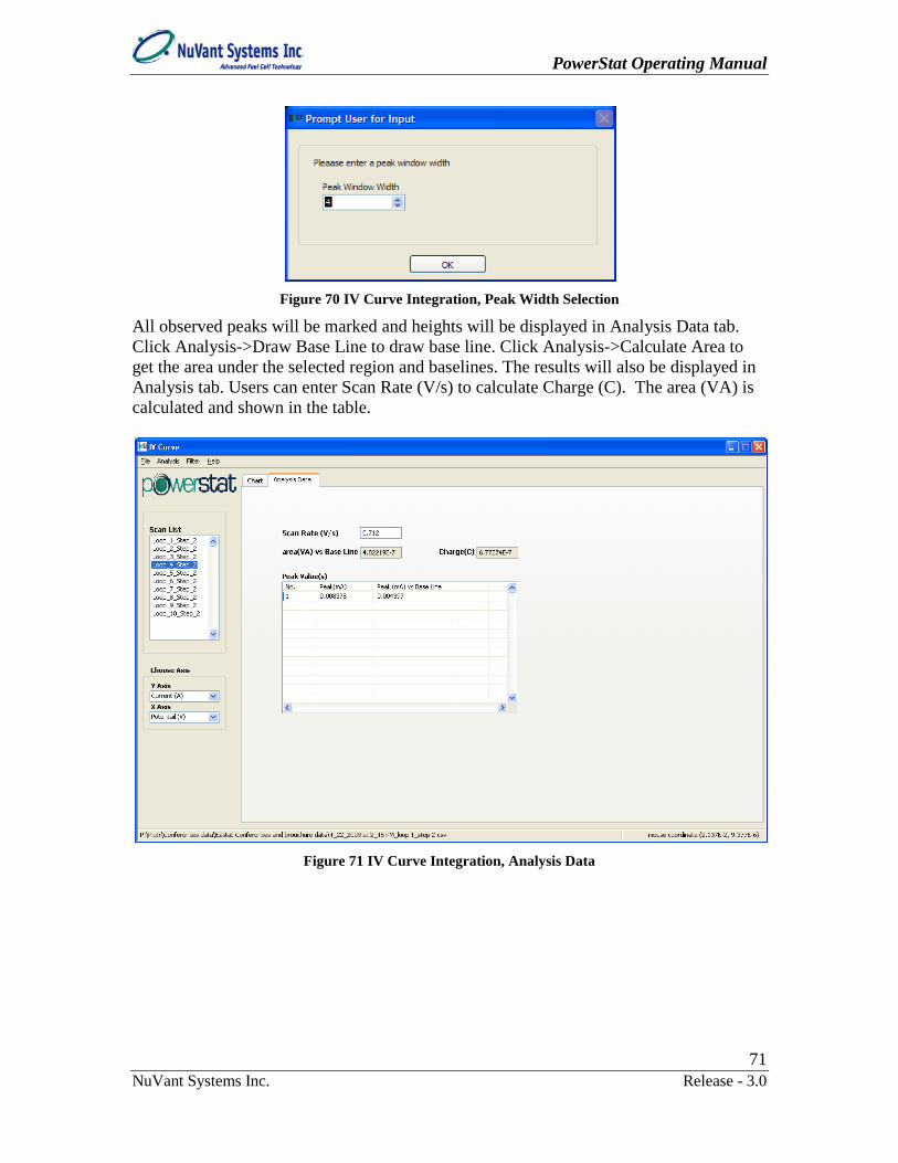
All observed peaks will be marked and heights will be displayed in Analysis Data tab. Click Analysis->Draw Base Line to draw base line. Click Analysis->Calculate Area to get the area under the selected region and baselines. The results will also be displayed in Analysis tab. Users can enter Scan Rate (V/s) to calculate Charge (C). The area (VA) is calculated and shown in the table.
Figure 71 IV Curve Integration, Analysis Data

PowerStat Operating Manual
72 NuVant Systems Inc. Release - 3.0
INDEX
#Loop Reps ......................................... 54 ABORT .............................................. 65 Absolute Value .................................. 50 auxiliary control .................................. 59 Background Potential ....................... 54 Base Line ............................................ 52 Base Line (V) ..................................... 52 battery cycling ............................. 30, 44 Cell Enable Switch ...................... 14, 61 Check Device ..................................... 23 Choose Device .................................... 23 Chronoamperometry ........................... 57 Chronopotentiometry .......................... 57 CONTINUE ................................. 64, 65 Control and Data Acquisition ............. 20 Control Type ....................................... 27 Counter .............................................. 14 Counter electrode ................................ 15 CPU ..................................................... 19 csv files ............................................... 64 current density ..................................... 68 DAQ .............................................. 16, 64 Delete This Step ................................. 27 Differential Pulse Voltammetry .... 52, 53 EDIT RECIPE ................................... 25 Electrostatic Discharge ....................... 10 External Input ................................... 14 Fast Scan ................................. 50, 51, 66 feedback control .......................... 37, 44 filter ............................................... 68, 69 Final Potential Time (s) .................... 51 First Vertex Voltage ............................ 56 Front Panel .................................... 13, 14 Go To Next Step ................................ 27 Go To Prev Step ................................ 27 Go To Step # ...................................... 27 graph ................................................... 60 Initial Potential Time (s) ................... 51 Initial Ramp Potential ...................... 50 Insert A New Step ............................. 27 Interval Time ....................................... 52 IV Curve ...................................... 25, 66 LabVIEW Runtime Engine ................. 18 Logging Duration(ms) ........................ 54
Logging Duration(s)............................ 51 Loop to Step# ...................................... 54 loops .................................................... 54 Manual Potential ............................... 64 Mark Peak ........................................... 70 Material Safety Data Sheets ................ 10 NEW RECIPE ................................... 25 NI USB-6221 (OEM) ......................... 23 NI-DAQmx ......................................... 18 noise .................................................... 68 Normal Pulse Voltammetry ................ 52 Number of Scans ................................. 56 OCV .............................................. 28, 50 On/Off ................................................ 66 onboard function generator ................. 19 Output Potential Auto/Manual .. 64, 65 PAUSE ............................................... 64 peak ............................................... 69, 70 Potential Step ............................... 28, 51 PotentioSTAT 4th Range IR
Compensation Switch ..................... 63 PowerStat . 2, 10, 11, 13, 14, 18, 20, 27,
51, 56, 61, 62, 64 PowerWare ................ 18, 20, 24, 25, 62 Previous .............................................. 49 Pulse Time .......................................... 52 Pulse Voltammetry............................ 52 PV amplitude ..................................... 52 PV Amplitude ..................................... 52 PV Step Size ....................................... 52 QUIT .................................................. 25 Quit Editor .......................................... 61 Ramp ...................................... 28, 49, 63 Ramp From ......................................... 49 Ramp to ............................................... 51 Rear Panel ........................................... 16 Recipe Editor ...................................... 25 recipe files ..................................... 22, 26 Recipe Step Table .............................. 26 Reference electrode ............................. 15 Reference Electrode .......................... 14 Reload................................................. 62 Reverse Ramp.................................... 50 Run Screen ................................... 61, 62

PowerStat Operating Manual
73 NuVant Systems Inc. Release - 3.0
Running PowerStat ............................ 61 save filtered data ................................. 69 scan rate ........................................ 51, 57 Scan Rate (V/s) .................................. 50 Second Vertex Voltage ....................... 56 Set/Final Potential ............................. 52 Set/Final Potential (V) .................. 51, 52 Signal Type ................ 28, 29, 49, 50, 51 Soak .............................................. 28, 63 Software Installation ........................... 18 Square Wave Voltammetry ........... 52, 53 Standard + Cut Off ........................... 46 standard potential .................... 30, 31, 33 Standby Potential (V) ....................... 54 START ......................................... 64, 65
Start Screen ............................. 20, 22, 62 Start Voltage ....................................... 56 Step Description .................................. 54 Step Duration .................................... 50 Step Potential ...................................... 56 Step Size ............................................. 50 timing .................................................. 19 Total Duration of Current Step ....... 50 USB ............................. 16, 17, 18, 20, 23 waveform ...................................... 51, 56 Working ............................................. 14 Working electrode ......................... 15, 31 working sense...................................... 15 X-axis .................................................. 68 Y-axis .................................................. 68