powervalue 31/11 t 10/20 kva user manual - ups service page 9/37 abb modifications reserved 3...
TRANSCRIPT

4NWP100559R0001_OPM_ABB_PVA31-11-T_10-20kVA_EN_140626 Page 1/37 ABBModifications reserved
PowerValue 31/11 T 10/20 kVAUser Manual
4NWP100559R0001_OPM_ABB_PVA31-11-T_10-20kVA_EN_140626
© Copyright 2014 ABB, All rights reserved.

4NWP100559R0001_OPM_ABB_PVA31-11-T_10-20kVA_EN_140626 Page 2/37 ABBModifications reserved
This page left intentionally blank

4NWP100559R0001_OPM_ABB_PVA31-11-T_10-20kVA_EN_140626 Page 3/37 ABBModifications reserved
FOREWORD
The UPS system operates with mains, battery or bypass power. It contains components that carry highcurrents and voltages. The properly installed UPS system is grounded to earth and IP 20 rated againstelectrical shock and foreign objects.OPERATIONS INSIDE THE UPS MUST BE PERFORMED BY A SERVICE ENGINEER FROMTHE SUPPLIER OR FROM AN AGENT AUTHORIZED BY THE SUPPLIER.
This user manual contains guidelines to check delivery, installing and commissioning of the UPS and isintended for people who plan the installation, install, commission and use or service the UPS. Thereader is expected to know the fundamentals of electricity, wiring, electrical components and electricalschematic symbols.
THE INSTRUCTIONS IN THIS MANUAL SHOULD BE FOLLOWED DURING INSTALLATION,OPERATION AND MAINTENANCE OF THE UPS AND BATTERIES.
Read carefully all instructions and save this manual for future reference.
SYMBOLS
The following symbols are used in this manual, the list below describes each symbol.
WARNING: DANGER OF ELECTRICAL IMPACT
NOTE: READ THE INFORMATION, IN ORDER TO AVOID EQUIPMENT DAMAGES
PROTECTIVE GROUNDING TERMINAL: A terminal which must be connected to earthground prior to making any other connection to the equipmentA terminal to which or from which an alternating current or voltage (AC) may be applied orsuppliedA terminal to which or from which a direct current or voltage (DC) may be applied orsupplied
Battery
Power On, Idle or shutdown the UPS
Overload indication
Recycle
Do not dispose with ordinary trash

4NWP100559R0001_OPM_ABB_PVA31-11-T_10-20kVA_EN_140626 Page 4/37 ABBModifications reserved
CONTENTS
FOREWORD ........................................................................................................................ 3SYMBOLS ............................................................................................................................ 31 SAFETY INSTRUCTIONS ............................................................................................. 6
1.1 Operator precautions .......................................................................................................61.2 Environmental Considerations ........................................................................................61.3 Declaration of Safety conformity and CE marking .........................................................61.4 Inquiries .............................................................................................................................71.5 Operation ...........................................................................................................................7
2 MAINTENANCE ............................................................................................................ 82.1 Battery Recycling..............................................................................................................8
3 GENERAL CHARACTERISTICS .................................................................................. 93.1.1 UPS front view .............................................................................................................93.1.2 UPS rear view ..............................................................................................................93.1.3 External battery cabinet front view .............................................................................103.1.4 External battery cabinet rear view ..............................................................................10
4 INSTALLATION .......................................................................................................... 114.1 Delivery, Transportation, Positioning and Storage ......................................................11
4.1.1 Receipt of the UPS and visual inspection...................................................................114.1.2 Unpacking..................................................................................................................114.1.3 UPS storage ..............................................................................................................124.1.4 Planning before the installation ..................................................................................12
4.2 Electrical Installation ......................................................................................................124.2.1 Commissioning ..........................................................................................................124.2.2 Connections ...............................................................................................................13
4.3 Batteries ..........................................................................................................................194.3.1 In-built batteries .........................................................................................................194.3.2 External battery cabinets ...........................................................................................20
4.4 Backfeed Protection .......................................................................................................204.5 Emergency Power Off (EPO) ..........................................................................................214.6 Installation Checklist ......................................................................................................21
5 OPERATION ............................................................................................................... 225.1 Control Panel ..................................................................................................................22
5.1.1 LEDs ..........................................................................................................................225.1.2 Selection Keys ...........................................................................................................235.1.3 LCD Display ...............................................................................................................23
5.2 Operating Mode ..............................................................................................................245.3 UPS Start-up and Shutdown ..........................................................................................25
5.3.1 UPS start-up ..............................................................................................................255.3.2 UPS Shutdown ..........................................................................................................255.3.3 Parallel UPS system ..................................................................................................26
5.4 UPS Operation ................................................................................................................275.4.1 Changing the operating-mode ....................................................................................275.4.2 Navigation..................................................................................................................27
4NWP100559R0001_OPM_ABB_PVA31-11-T_10-20kVA_EN_140626 Page 5/37 ABBModifications reserved
6 COMMUNICATION ..................................................................................................... 326.1 RS-232 port......................................................................................................................326.2 USB port ..........................................................................................................................326.3 Network Management Card (Optional) ..........................................................................32
6.3.1 Installing a Serial Network Management Card (optional) ............................................336.3.2 AS400 Dry Contact card ............................................................................................336.3.3 Monitoring Software ...................................................................................................33
7 TROUBLESHOOTING ................................................................................................ 347.1 Fault identification and rectification ..............................................................................34
7.1.1 Troubleshooting without an error message ................................................................347.1.2 Troubleshooting based on error message ..................................................................34
8 TECHNICAL SPECIFICATION ................................................................................... 36

4NWP100559R0001_OPM_ABB_PVA31-11-T_10-20kVA_EN_140626 Page 6/37 ABBModifications reserved
1 SAFETY INSTRUCTIONS
1.1 Operator precautions
The user must follow the precautions and only perform the described operations. Also in thesemeasures, the operator of the UPS System must adhere to the instructions in this manual. Anydeviations from the instructions could be dangerous to the user or cause accidental load loss.
The only user operations permitted are:- Use of the LCD control panel (LCD Display) and Maintenance Bypass (if present)- Start up and shut down of the UPS (excluding the commissioning start up)- Operation of additional connectivity devices
THE SUPPLIER DOES NOT TAKE ANY RESPONSIBILITY FOR DAMAGES CAUSED THROUGHWRONG MANIPULATIONS OF THE UPS SYSTEM.
WARNING!
IT IS PROHIBITED TO REMOVE ANY SCREWS FROM THE UPSSYSTEM OR FROM THE BATTERY CABINET: DANGER OFELECTRICAL SHOCK.
WARNING!
HIGH FAULT CURRENTS (LEAKAGE CURRENTS):BEFORE CONNECTING THE MAINS YOU MUST ENSURE THATTHERE IS A PROPER EARTH CONNECTION!
WARNING!
THE USER MUST DISPLAY A WARNING SHIELD ON ALL PRIMARYUPS CIRCUIT BREAKERS. THE SERVICE PERSONNEL HAS TO BEINFORMED ABOUT DANGEROUS VOLTAGES. THE WARNINGPANELS MUST CONTAIN THE FOLLOWING TEXT: “BEFORESTARTING WITH THE MAINTENANCE WORK ON THE CIRCUITBREAKERS, MAKE SURE THE UPS IS ISOLATED.”
1.2 Environmental Considerations
To operate the UPS at the best efficiency point, your installation site should meet the environmentalparameters outlined in this manual. Excessive amount of dust or moisture in the operating environmentmay cause damage or lead to malfunction. The UPS should be always protected from the outsideweather and sunshine. The operating environment must meet the weight, airflow, size and clearancerequirements specified in the technical datasheet.
Under no circumstances, the UPS should be installed in an airtight room, in the presence of flammablegases, or in an environment exceeding environmental requirements here below.
An ambient temperature of +20°C to +25°C is recommended to achieve a long life of the UPS andbatteries. The cooling air entering the UPS must not exceed +40 °C and the humidity should be below95% (non-condensing).
1.3 Declaration of Safety conformity and CE marking
PowerValue 31/11 T is designed, manufactured and commercialized in accordance with the standardEN ISO 9001 of Quality Management Systems. The marking shows the conformity to the EEC Directiveby means of the application of the following standards in accordance with the specifications of theharmonized standards:
• 2006/95/EC Low voltage directive.• 2004/108/EC Electromagnetic Compatibility directive (EMC).
4NWP100559R0001_OPM_ABB_PVA31-11-T_10-20kVA_EN_140626 Page 7/37 ABBModifications reserved
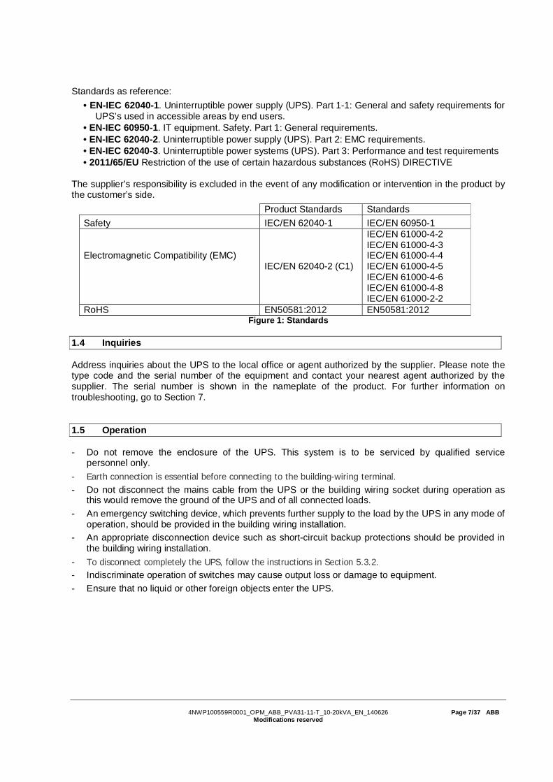
Standards as reference:• EN-IEC 62040-1. Uninterruptible power supply (UPS). Part 1-1: General and safety requirements for
UPS’s used in accessible areas by end users.• EN-IEC 60950-1. IT equipment. Safety. Part 1: General requirements.• EN-IEC 62040-2. Uninterruptible power supply (UPS). Part 2: EMC requirements.• EN-IEC 62040-3. Uninterruptible power systems (UPS). Part 3: Performance and test requirements• 2011/65/EU Restriction of the use of certain hazardous substances (RoHS) DIRECTIVE
The supplier’s responsibility is excluded in the event of any modification or intervention in the product bythe customer’s side.
Product Standards StandardsSafety IEC/EN 62040-1 IEC/EN 60950-1
Electromagnetic Compatibility (EMC)IEC/EN 62040-2 (C1)
IEC/EN 61000-4-2IEC/EN 61000-4-3IEC/EN 61000-4-4IEC/EN 61000-4-5IEC/EN 61000-4-6IEC/EN 61000-4-8IEC/EN 61000-2-2
RoHS EN50581:2012 EN50581:2012Figure 1: Standards
1.4 Inquiries
Address inquiries about the UPS to the local office or agent authorized by the supplier. Please note thetype code and the serial number of the equipment and contact your nearest agent authorized by thesupplier. The serial number is shown in the nameplate of the product. For further information ontroubleshooting, go to Section 7.
1.5 Operation
- Do not remove the enclosure of the UPS. This system is to be serviced by qualified servicepersonnel only.
- Earth connection is essential before connecting to the building-wiring terminal.- Do not disconnect the mains cable from the UPS or the building wiring socket during operation as
this would remove the ground of the UPS and of all connected loads.- An emergency switching device, which prevents further supply to the load by the UPS in any mode of
operation, should be provided in the building wiring installation.- An appropriate disconnection device such as short-circuit backup protections should be provided in
the building wiring installation.- To disconnect completely the UPS, follow the instructions in Section 5.3.2.- Indiscriminate operation of switches may cause output loss or damage to equipment.- Ensure that no liquid or other foreign objects enter the UPS.

4NWP100559R0001_OPM_ABB_PVA31-11-T_10-20kVA_EN_140626 Page 8/37 ABBModifications reserved
2 Maintenance
WARNING!
ONLY QUALIFIED MAINTENANCE PERSONNEL SHOULD CARRY OUTREPAIRING AND BATTERY REPLACEMENTS.
Before carrying out any kind of service and/or maintenance, disconnect the batteries. Verify that nocurrent is present and no hazardous voltage exists in the capacitor or BUS capacitor terminals.
WARNING!
BATTERY REPLACEMENT SHOULD ONLY BE PERFORMED BYQUALIFIED PERSONNELEVEN AFTER THE UNIT IS DISCONNECTED FROM THE MAINS POWERSUPPLY, COMPONENTS INSIDE THE UPS ARE STILL CONNECTED TOTHE BATTERY.
WARNING!
THE BATTERY CIRCUIT IS NOT ISOLATED FROM THE INPUT VOLTAGE.HAZARDOUS VOLTAGES MAY OCCUR BETWEEN THE BATTERYTERMINALS AND THE GROUND. VERIFY THAT NO VOLTAGE ISPRESENT BEFORE SERVICING.
Batteries have high short-circuit currents and pose high risks of electric shock. Take all precautionarymeasures specified below:
- Remove all jewelry, wristwatches, rings and other metal objects- Use only tools with insulated grips and handles- Do not lay tools or metal parts on top of batteries- Wear rubber gloves and boots- Disconnect the charging source prior to connecting or disconnecting the battery terminals.
- If the battery service life (3~5 years at 25°C ambient temperature) has been exceeded, the batteriesmust be replaced. In this case please contact your dealer.- The UPS should be charged once every 4 to 6 months if it has not been used for a long time. Thebatteries charge to 90% capacity in approximately 4 hours. However, it is recommended that thebatteries charge for 48 hours after long-term storage.
- In high temperature regions, the battery should be charged and discharged every 2 months. Thestandard charging time should be of at least 12 hours.
- Under normal conditions, the battery life lasts 3 to 5 years. In case the battery is not in good conditions,earlier replacement should be made.
- When the discharging time is less than 50% of specified after full charged, the battery may need to bereplaced. Please check the battery connection or contact your local dealer to order new battery.
- Replace batteries with the same number and same type of batteries.
- Do not replace the batteries individually. All batteries should be replaced at the same time following theinstructions of the battery supplier.
- Replace fuses only by devices of the same type and of the same amperage in order to avoid firehazards.
2.1 Battery Recycling
WARNING!NEVER DISPOSE BATTERIES ON FIRE AS THEY MAY EXPLODE.DO NOT OPEN OR MUTILATE THE BATTERIES.RELEASED ELECTROLYTE IS HARMFUL TO THE SKIN AND EYES.
Discard appropriately the UPS, battery module and batteries and follow your local laws and regulations.
4NWP100559R0001_OPM_ABB_PVA31-11-T_10-20kVA_EN_140626 Page 9/37 ABBModifications reserved
3 General Characteristics
The UPS and external battery cabinet mechanical structure are indicated in the tables and pictures ofthis section.
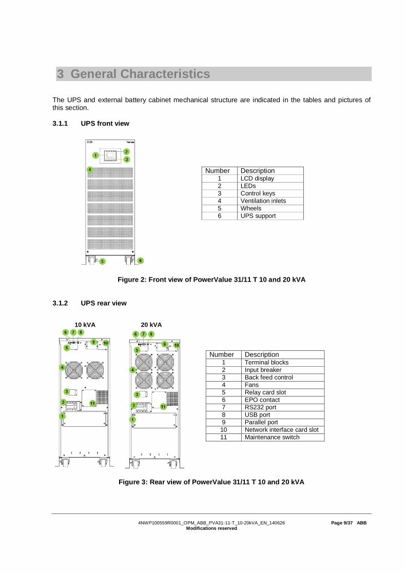
3.1.1 UPS front view
Figure 2: Front view of PowerValue 31/11 T 10 and 20 kVA
3.1.2 UPS rear view
10 kVA 20 kVA
Figure 3: Rear view of PowerValue 31/11 T 10 and 20 kVA
Number Description1 LCD display2 LEDs3 Control keys4 Ventilation inlets5 Wheels6 UPS support
Number Description1 Terminal blocks2 Input breaker3 Back feed control4 Fans5 Relay card slot6 EPO contact7 RS232 port8 USB port9 Parallel port
10 Network interface card slot11 Maintenance switch

4NWP100559R0001_OPM_ABB_PVA31-11-T_10-20kVA_EN_140626 Page 10/37 ABBModifications reserved
3.1.3 External battery cabinet front view
Figure 4: Front view of external battery cabinet
3.1.4 External battery cabinet rear view
Figure 5: Rear view of external battery cabinet
Number Description1 Ventilation inlets2 Wheels3 UPS support
Number Description1 Ventilation inlets2 Fuse holder3 Connection terminals4 Wheels5 UPS support

4NWP100559R0001_OPM_ABB_PVA31-11-T_10-20kVA_EN_140626 Page 11/37 ABBModifications reserved
4 Installation
4.1 Delivery, Transportation, Positioning and Storage
4.1.1 Receipt of the UPS and visual inspection
Upon receiving the UPS, carefully examine the packing container and the UPS for any sign of physicaldamage. In case of damage, notify immediately the carrier.
The packing container of the UPS protects it from mechanical and environmental damage. To increaseits protection, the UPS is wrapped with a plastic sheet. Preserve the packaging for later re-use.
4.1.2 Unpacking
To unpack the unit, follow the steps below:
1. Using a forklift, position the unit in the placewhere it will be installed. The UPS haswheels that makes it easy to move be movedafter unpacked but avoid dragging it long notto damage the wheels.
2. Remove the caron box from the top of theunit.
3. Remove the protection on the sides and topof the unit.
4. Using the wooden piece provided on the topof the UPS, slide the UPS out of the palletwith care.
5. Install the side mounting brackets (used for shipping) back to the unit to ensure higher stability ofthe UPS. If desired, the UPS can also be fixed to the floor with M8 bolts.

4NWP100559R0001_OPM_ABB_PVA31-11-T_10-20kVA_EN_140626 Page 12/37 ABBModifications reserved
Examine the UPS for any sign of damage and ensure that the received UPS corresponds to the materialindicated in the delivery note. Notify your carrier or supplier immediately if damage is apparent. Thecontent of the package is:
- 1 x PowerValue 31/11 T UPS- 1 x User manual- 1 x parallel cable- 1 x parallel port cover plate- 1 x Metal fork (1 pole)- 1 x Metal fork (3 poles)- 1 x Cable for connections from M2 to metal fork- 2 x M5x12 HEX screw- 4 x cable glands- 1 x Monitoring Software CD
4.1.3 UPS storage
If you plan to store the UPS prior to use, keep the UPS in a dry, clean and cool storage room with anambient temperature between -15 °C and +60°C and humidity of less than 95% non-condensing. If thepacking container has been removed, protect the UPS from dust. Keep the UPS always in uprightposition and do not drop the equipment.
4.1.4 Planning before the installation
The appropriate place of installation for the unit is to be selected in such a way that the danger ofdamage to the UPS is minimized and a long service life of the device is thus ensured. Please observethe following instructions:
- Install the UPS in an indoor area.- Leave 50 cm of space on each side of the cabinet to enable cooling airflow and ensure that thecirculation of air to the ventilation slits is not obstructed.- Avoid excessively high temperature and excessive moisture.- Make sure that the surface is solid and flat.- Note that water condensing may occur if the UPS is unpacked in a very low temperature environment.In this case, it is necessary to wait until the UPS is fully dried inside out before proceeding with theinstallation to avoid hazards and electric shock.
4.2 Electrical Installation
4.2.1 Commissioning
The UPS must be commissioned by a fully trained and authorized field service engineer before being putinto use. The commissioning of the UPS involves the connection of the UPS and batteries, theverification of the electrical installation and operating environment of the UPS, the controlled start-up andtesting of the UPS and customer training.
WARNING!
OPERATIONS INSIDE THE UPS MUST BE PERFORMED BY A SERVICEENGINEER FROM THE SUPPLIER OR FROM AN AGENT AUTHORIZEDBY THE SUPPLIER.
DO NOT OPERATE IN CASE OF PRESENCE OF WATER OR MOISTURE.
WHEN OPENING OR REMOVING THE UPS-COVERS YOU ARE EXPOSEDTO DANGEROUS VOLTAGES.
PHYSICAL INJURY OR DEATH MAY HAPPEN, DAMAGE TO THE UPS ORTO THE LOAD EQUIPMENT MAY OCCUR IF THESE INSTRUCTIONS AREIGNORED
To ensure correct operation of the UPS and batteries, it is necessary to provide the mains cables withappropriate fuse protection.

4NWP100559R0001_OPM_ABB_PVA31-11-T_10-20kVA_EN_140626 Page 13/37 ABBModifications reserved
4.2.2 Connections
Before installing the electrical wiring, check the nominal amperage of your incoming feeder.
WARNING!
THE CABLING CONNECTIONS MUST BE CARRIED OUT BY QUALIFIEDELECTRICAL PERSONNEL.DO NOT USE THE WALL SOCKET AS THE INPUT POWER SOURCE FORTHE UPS. ITS RATED CURRENT IS NOT ADEQUATE TO THE FEED THEUPS AND MAY BURN THE SOCKET.
The UPS is cabled through the terminal blocks as indicated in Figure 6.
Figure 6: Terminal blocks
4.2.2.1 Wiring Recommendation
It is recommended to use the following cables for the installation.
Position 10kVA 20 kVA
Mains 1Input L1, L2, L3 Min section: 2.5 mm2
Max section: 4 mm2Min section: 6 mm2
Max section: 10 mm2
Input breaker, internal 40A 60A
Mains 2Input M2, N (bypass) Min section: 10 mm2
Max section: 13 mm2Min section: 21 mm2
Max section: 25 mm2
Input breaker M2(bypass) 63A 100A
Battery Circuit breaker 40A 400V 80A 400V
Output Output L, N Min section: 10 mm2
Max section: 13 mm2Min section: 21 mm2
Max section: 25 mm2
ExternalBattery cabinet
Positive, Negative andneutral poles
Min section: 10 mm2
Max section: 13 mm2Min section: 21 mm2
Max section: 25 mm2
Back feed Bypass protection (M2)
AC contactor of minimally 100A rating, e.g. a three phasecontactor of 3* 40A with the poles wired together (e.g. ABBAF-26)Control coil rated according to bypass supply.
ProtectingEarth
Input, bypass andoutput Max section: 13 mm2 Max section: 25 mm2
Table 1: Wiring dimensioning
Green or green and yellow wires should be used to distinguish the earth cable.

4NWP100559R0001_OPM_ABB_PVA31-11-T_10-20kVA_EN_140626 Page 14/37 ABBModifications reserved
4.2.2.2 Procedure
1. Open the terminal block cover located on therear panel of the UPS.
2. Remove the protective plates of the cableentries. (The bypass hole should remain closedfor safety purposes if it is not used)
3. Connect the wires according to the illustrations in the subsections that follow according to yourconfiguration (11 or 31, single or dual input feed). Pass the cables through the holes from the bottomto the top installing also the cable glands provided with the UPS.
Note: The terminal of the phase cable must have a ring connector in some configurations.
11 configuration – Single input feed Phase cable11 configuration – Dual input feed Phase cable11 configuration – Single input feed L3 phase cable
Note: If the UPS is used as a standalone UPS, jumpers 1 and 2 must be connected. If the UPSs are usedin parallel configuration, the jumper between JP1 and JP2 must be removed.
4. Check that all wires have been properly connected.
5. Close the terminal box with the protectivecover. This is very important to prevent accessto energized cables and metal forks.
6. Install the output breakers between the outputterminal and the load. The breaker should havea leakage current protective function accordingto the UPS voltage and current ratings.

4NWP100559R0001_OPM_ABB_PVA31-11-T_10-20kVA_EN_140626 Page 15/37 ABBModifications reserved
4.2.2.2.1 Single phase input – single phase output (11)
Single Input Feed
1. Connect the neutral cable to the neutral terminal of mains 2. Note that the mains neutral is connectedinternally to mains 1. For this, there is no need to connect the neutral cable to the mains 1 terminal.
2. Connect the 3-pole fork provided with the UPS between terminals L1, L2 and L3.
Figure 7: 3-pole fork installation
3. Connect the M2 cable provided with the UPS (refer to section 4.2.2.1) between terminal M2 and thefork (use the M5 screw provided in the fork connection.
4. Connect the phase cable from the mains to the 3-pin fork.
Figure 8: Single feed (11) wiring diagram

4NWP100559R0001_OPM_ABB_PVA31-11-T_10-20kVA_EN_140626 Page 16/37 ABBModifications reserved
Dual Input Feed
1. Connect the neutral cables to the neutral terminals (mains 1 and mains 2).2. Connect the 3-pole fork provided with the UPS between terminals L1, L2 and L3.
Figure 9: 3-pole fork installation
3. Connect the phase cables accordingly.
Figure 10: Dual feed (11) wiring diagram

4NWP100559R0001_OPM_ABB_PVA31-11-T_10-20kVA_EN_140626 Page 17/37 ABBModifications reserved
4.2.2.2.2 Three phase input – single phase output (31)
Single Input Feed
1. Connect the neutral cable to the neutral terminal (main 2). Note that the mains neutral is connectedinternally in the UPS. For this, there is no need to connect the neutral cable to the mains 1 terminal.
2. Connect the 1-pole fork provided with the UPS to terminal L3.
Figure 11: 1-pole fork installation
3. Connect the cable provided with the UPS between M2 and terminal L3.4. Connect the phase cables to the corresponding terminals.
Figure 12: Single feed (31) wiring diagram
Dual Input Feed
1. Connect the neutral cable to the neutral terminal (main 2). Note that the mains neutral isconnected internally in the UPS. Isolate and do not connect neutral of mains 1 as there is apossibility bypass current would return through and overload the smaller cable of mains 1.
2. Connect the phase cables to L1, L2, L3 and M2.
Figure 13: Dual feed (31) wiring diagram
4NWP100559R0001_OPM_ABB_PVA31-11-T_10-20kVA_EN_140626 Page 18/37 ABBModifications reserved
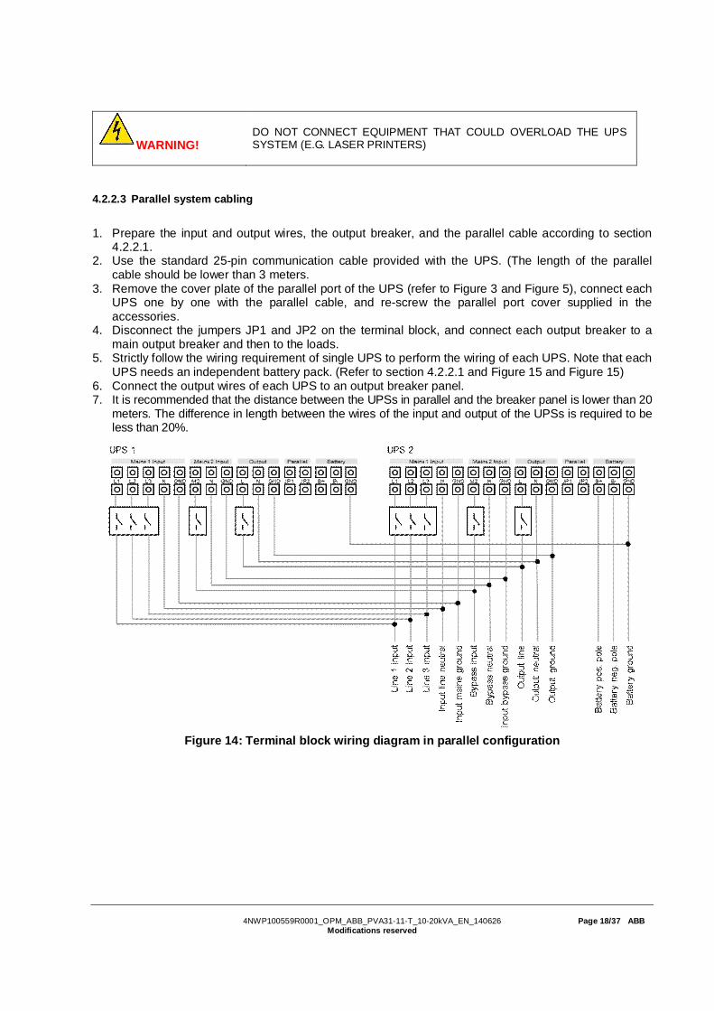
WARNING!DO NOT CONNECT EQUIPMENT THAT COULD OVERLOAD THE UPSSYSTEM (E.G. LASER PRINTERS)
4.2.2.3 Parallel system cabling
1. Prepare the input and output wires, the output breaker, and the parallel cable according to section4.2.2.1.
2. Use the standard 25-pin communication cable provided with the UPS. (The length of the parallelcable should be lower than 3 meters.
3. Remove the cover plate of the parallel port of the UPS (refer to Figure 3 and Figure 5), connect eachUPS one by one with the parallel cable, and re-screw the parallel port cover supplied in theaccessories.
4. Disconnect the jumpers JP1 and JP2 on the terminal block, and connect each output breaker to amain output breaker and then to the loads.
5. Strictly follow the wiring requirement of single UPS to perform the wiring of each UPS. Note that eachUPS needs an independent battery pack. (Refer to section 4.2.2.1 and Figure 15 and Figure 15)
6. Connect the output wires of each UPS to an output breaker panel.7. It is recommended that the distance between the UPSs in parallel and the breaker panel is lower than 20
meters. The difference in length between the wires of the input and output of the UPSs is required to beless than 20%.
Figure 14: Terminal block wiring diagram in parallel configuration

4NWP100559R0001_OPM_ABB_PVA31-11-T_10-20kVA_EN_140626 Page 19/37 ABBModifications reserved
Figure 15: Parallel Installation Diagram
To add or to remove a UPS to an existing system, go to section 5.3.3
4.3 Batteries
Each battery block consists of 24 batteries of 12V in series. The nominal DC voltage of a battery block istherefore 288Vdc.
4.3.1 In-built batteries
Some models of PowerValue 31/11 T have with interbal batteries. These batteries are already installedand connected when the units are delivered. To replace, reduce or increase the amount of batteries,connect the batteries as indicated in Figure 16. Connect the terminals to their matching color terminals.
1x24 batteries 2x24 batteries
Figure 16: Internal batteries connections

4NWP100559R0001_OPM_ABB_PVA31-11-T_10-20kVA_EN_140626 Page 20/37 ABBModifications reserved
4.3.2 External battery cabinets
WARNING!
BATTERY REPLACEMENT AND CONNECTIONS SHOULD ONLY BEPERFORMED BY QUALIFIED PERSONNEL
To achieve longer back up times, connect in parallel several string (with the same amount of batteries inseries – 24 pieces).
1. If the UPS has internal batteries, disconnect the battery connectors.
2. Connect a battery breaker between the external battery cabinet and the UPS according to Table 2.
UPS power # phases Fuse10 kVA 1 80 A10 kVA 3 25 A20 kVA 1 160 A20 kVA 3 50 A
Table 2: Recommended fuse rating
3. Set the battery breaker to the position OFF and connect the batteries (24 batteries in series).4. Connect the battery cabinet to the battery terminals in the rear of the UPS.
5. Reconnect the internal battery cables (if present).6. Connect the input wires of the UPS and then set the battery breaker to the position ON. The UPS will
start charging the batteries.
4.4 Backfeed Protection
To support protection against UPS back feed currents, an additional external isolation device must beinstalled in the bypass path according to Figure 17. Remove the protecting cover of the back feedterminals on the back of the UPS and install a contactor (see Table 1 for dimensioning). Install the backfeed control wire according to relevant wiring rules.

4NWP100559R0001_OPM_ABB_PVA31-11-T_10-20kVA_EN_140626 Page 21/37 ABBModifications reserved
Figure 17: Back feed magnetic contactor installation
4.5 Emergency Power Off (EPO)
The EPO connector gives the user the possibility to block the output of the UPS in case of anemergency. As a default, the EPO is Normally Closed (NC) by a jumper in the rear panel. If the jumper isremoved, the UPS output will not supply energy to the load until the EPO status is again modified.
Enable the EPO status Disable the EPO status
To recover to normal status, close the EPO connector. Then, enter the LCD menu (refer to Section5.4.2.3) to clear the EPO status. The UPS alarm will stop and will transfer to bypass mode. To transfer toonline-mode, press and hold the power-on button for a few seconds.
Note: EPO connector can be configured as Normally Closed (NC) o Normally Opened (NO) through theUSB or RS232 port. Contact your local supplier for further information before modifying the settings.
4.6 Installation Checklist
All packing materials and restraints have been removed from each module.Each module in the UPS system is placed in the installed location.All conduits and cables are properly routed to the UPS and auxiliary enclosures.All power cables are properly sized and terminated.A ground conductor is properly installed.Battery enclosure installation instructions have been completed.Air conditioning equipment is installed and operating properly.The area around the installed UPS system is clean and dust-free.Adequate workspace exists around the UPS and other cabinets.Adequate lighting is provided around all UPS equipment.Any optional accessories are mounted in their installed location and properly wired.Summary alarms and/or building alarms are wired appropriately. (Optional)Start-up and operational checks performed by authorized service personnel.All network connections are completed.

4NWP100559R0001_OPM_ABB_PVA31-11-T_10-20kVA_EN_140626 Page 22/37 ABBModifications reserved
5 OPERATION
This chapter describes how to operate the UPS through the LCD display.
WARNING!
ONLY PERSONS WHICH HAVE BEEN TRAINED BY SERVICETECHNICIANS OF THE SUPPLIER OR HIS AUTHORIZED SERVICEPARTNERS ARE ALLOWED TO OPERATE THE CONTROL PANEL OFTHE UPS.
ALL OTHER INTERVENTIONS ON THE UPS SYSTEM HAVE TO BEDONE ONLY BY SERVICE TECHNICIANS OF THE SUPPLIER.
The only user permitted operations are:
· Operate the LCD display· Start up and shut down of the UPS of the user field (excluding the commissioning start up)· Operation of additional SNMP adapters and their software
5.1 Control Panel
The user-friendly control panel is composed of LEDs, an LCD display and four selection keys.
Figure 18: Control Panel
5.1.1 LEDs
The LEDs gives the UPS mode or a faulty situation at a glance. The LEDs may blink or stay constantlyon depending on the UPS status. Table 3 indicates the meaning of each LED.
UPS status LED Normal(green)
LED Battery(yellow)
LED Bypass(yellow)
LED Fault(red)
Bypass mode / no power in output - - A DBypass mode / powered output - - B DUPS is turning ON C C C COnline mode B - - DBattery mode B B - DECO mode B - B DBattery test mode C C C CFault mode - - D BWarning D D D A
Legend:A: LED flashingB: constantly lightenedC: lightened circularlyD: depends on the failure/warning
Table 3: LEDs indication

4NWP100559R0001_OPM_ABB_PVA31-11-T_10-20kVA_EN_140626 Page 23/37 ABBModifications reserved
5.1.2 Selection Keys
The Button Function Illustration
Power On/Off Turn on and off the UPS or change operating mode.
Scroll up Enter/Exit the menus and scroll across the screens.
Scroll down Scroll down the menu
Select / Edit Select and confirm settings.
To see how to operate the UPS, go to Section 5.4.
5.1.3 LCD Display
The LCD display gives the user a complete overview on the status of the UPS. It shows information onthe input, output, battery, load parameters, working mode and the settings on voltage, frequency andbypass presence.
It has two main backlight colors. The standard color is a blue background with white texts. In case of acritical alarm, the backlight color changes to orange with dark text. The buzzer also indicates differentUPS status. Figure 19 indicates the buzzer status meanings.
UPS condition Buzzer statusActive failure ContinuousActive warning Beep every second
Battery output UPS on battery: Beeps every 4 secondsLow battery: buzzer beeps every second
Bypass Beep every 2 minutesOverload Beep twice every second
Figure 19: Definition of Alarms
When powering on, the UPS display enters the UPS status menu.
The status screen provides the following information:- Status summary, including operating mode and load information- Alarm status, if present (including fault and warning information)- Battery and charger status (including battery voltage, charge level and charger status)- Current runtime informationIf the user does not press any keys for more than 15 minutes, the UPS leads to the status display.
Figure 20: Main UPS screen

4NWP100559R0001_OPM_ABB_PVA31-11-T_10-20kVA_EN_140626 Page 24/37 ABBModifications reserved
5.2 Operating Mode
Different symbols indicate the status and the operating mode of the UPS. Such symbols appear alwaysin the position indicated in Figure 21.
Figure 21: Operating mode
Status Symbol DescriptionOnline-mode UPS is running through the inverter (Online-mode)Battery-mode UPS running on battery.
Bypass-mode
The power used by the load is supplied from the mains power viainternal filter.Note that if there is a power failure and the UPS in on bypass, itwill not transfer back to mains or to battery-mode. (This onlyhappens if the UPS is in ECO-mode).
Stand-by-mode UPS is running on bypass but there is no power in the output.
ECO-mode
After the UPS is turned on, the power used by the load issupplied from the mains via internal filter if its power is in anacceptable range. This guarantees higher efficiency of the UPS.In case of mains failure, the UPS transfers to Online-mode orBattery-mode and the load is supplied continuously.
Note: ECO-mode can be enabled/disabled through the LCDsettings or through the monitoring software.Warning: The transfer time of UPS output from ECO-mode tobattery-mode is 10ms and not recommended for sensitive loads.
Converter-mode
In converter-mode, the UPS runs with fixed output frequency(50Hz or 60Hz). In case of mains power failure, the UPStransfers to battery-mode and the load is supplied continuously.
Note:- Converter-mode function can be enabled/disabled through theLCD settings or the monitoring software.- The load should be de-rated to 60% in converter-mode withsingle phase input. No de-rating is needed in three phase inputconfiguration.
WarningWarnings indicate abnormal situations that do not stop the UPSfrom working. In these cases, the UPS continues running but theuser should do corrective actions. See Section 7 for details.
Fault
In situations of failure, the UPS may disconnect the load ortransfer to bypass depending on the cause of the failure. In allcases, there will be a constant alarm and the backlight of theUPS will become red. See Section 7 for details.
Overload
When the UPS is in overload, unnecessary loads should bedisconnected one by one to decrease the load. The load shouldbe lower than 90% of its nominal power capacity in order to stopalarming.
Battery test UPS is performing a battery test.
Battery disconnected The battery is disconnected or defective. The UPS alarm sounds.

4NWP100559R0001_OPM_ABB_PVA31-11-T_10-20kVA_EN_140626 Page 25/37 ABBModifications reserved
5.3 UPS Start-up and Shutdown
Attention: The first time the UPS is started-up, the utility must be connected to the mains (no cold-start).This is to prevent turning on the UPS by mistake during transportation.IMPORTANT: Switch off the connected loads before turning on the UPS. Then switch on the loads one byone after the UPS is turned on. Switch off all of the connected loads before turning off the UPS.
WARNING!
INSTALLATION OPERATION AND OTHER SERVICE INTERVENTIONSON THE UPS SYSTEM HAVE TO BE PERFORMED BY SERVICETECHNICIANS AUTHORIZED BY THE SUPPLIER.
5.3.1 UPS start-up
With mains supply1. Check that all cables are connected correctly and well-fixed mechanically.2. Measure the power supply current and voltage to ensure it is energized.3. Connect the mains power to the UPS.4. Check that the battery cabinet breaker is on position ON (when using external battery cabinets).5. Set input breakers (M1 and M2) to position-on. The fans start running, the UPS will perform a self-
test and will then display the status menu.6. Press the power-on button for more than 1s, the alarm buzzer sounds and the UPS start-up takes
place.7. After a few seconds, the UPS goes to online-mode. If the mains power is abnormal, the UPS will
transfer to battery-mode without interruption of the UPS’s output power.
Cold Start (UPS start-up without mains supply)1. Check that all cables are connected correctly and well-fixed mechanically.2. Check that the battery cabinet breaker is on position ON (when using external battery cabinets).3. Press the power-on button. The UPS will perform a self-test and display the status screen.4. Press the power-on button continuously for more than 1s, the alarm buzzer sounds and the UPS
start-up takes place.5. After a few seconds, the UPS transfers to battery-mode. When the UPS is again supplied with power
from the mains, the UPS transfers to online-mode without interruption in the output of the UPS.
5.3.2 UPS Shutdown
With mains supply1. If the UPS is working on bypass-mode, go to step 3.2. If the UPS is on online-mode, press the power-on button continuously for more than 3s. The alarm
buzzer will sound and the UPS will transfer to bypass-mode. Note: the output is still energized.3. Disconnect the UPS from the mains power supply through the output breaker. A few seconds later
the display will shut down and the output voltage will be removed from the UPS output terminal.
In case the bypass has been disabled through the Settings menu, press the power-on button for morethan 3s to shutdown the UPS. The unit will change from online to stand-by-mode. Then, simplydisconnect the input power cable and a few seconds later the display will shutdown.
Without mains supply1. To power off the UPS, press the power on/off button continuously for more than 3s. The alarm
buzzer will sound for 3s and the output power will be immediately cut-off.2. After a few seconds, the display will shut down and the output voltage will be removed from the UPS
output terminal.
4NWP100559R0001_OPM_ABB_PVA31-11-T_10-20kVA_EN_140626 Page 26/37 ABBModifications reserved
5.3.3 Parallel UPS system
Installing a new parallel system1. Do not switch on the output breaker of each UPS. Switch on the input breaker of the each UPS and
the UPS will transfer to bypass.2. Observe the UPS displays to check if there are warnings or fault information. Measure the output
voltage of each UPS separately to check if the voltage difference between them is lower than 1V. Ifthe difference is higher than 1V, check the wiring.
3. Press the power-on button of one UPS. Each UPS will start up and all of them will transfer to theinverter at the same time.
4. Measure the output voltage of each UPS separately to check if the voltage difference between themis lower than 0.5V. If the difference is higher than 1V, the UPSs must be regulated.
5. Press the power-on button of one UPS. Each UPS will transfer to the bypass-mode. Switch on theoutput breaker of each UPS to parallel the output of all UPSs at the same time.
6. Press the power-on button of one UPS, each UPS will start up and they will work in parallel in onlinemode.
Adding a UPS to an existing systemRead carefully section 5.4 before following the procedure below.Note: The parallel system must have a main maintenance mechanical switch or static switch accordingto Figure 15.
1. Regulate the output voltage of the new UPS separately: check if the output voltage differencebetween the new UPS and the parallel system is lower than 0.5V.
2. Ensure that the bypass of the parallel system is working and the bypass setting is “enabled”.3. Remove the cover plate of the maintenance switch on the rear panel of each UPS. The UPS system
will transfer to bypass automatically.4. Set the own maintenance switch of each UPS from “UPS” to “BPS”.5. Switch off the main output breaker and the main input breaker. The UPS will shut down.6. Check that that there is no current in the output and that the UPS is switched off.7. Add the new UPS and reinstall the new UPS parallel system by following steps 1-7 of section 4.2.2.3.8. Switch on the main input breaker and the main output breaker, and set the main maintenance switch
or static switch from “BPS” to “UPS”.9. Set the UPS own maintenance switch from “BPS” to “UPS” and screw the maintenance cover plate
back again.10. Press the power-on button of one UPS. Each UPS will start up and all UPSs will run in parallel in
online mode.
How to remove a single UPS from a parallel system:Note: The parallel system must have a main maintenance mechanical switch or static switch accordingto Figure 15.
1. Ensure that the bypass is working and that he bypass setting is “enabled”.2. Remove the cover plate of maintenance switch on the rear panel of each UPS. The UPS system will
transfer to bypass automatically.3. Set the own maintenance switch of each UPS from “UPS” to “BPS”.4. Switch-off the main output breaker and the main input breaker. The UPSs will shutdown.5. Check that that there is no current in the output and that the UPS is switched off.6. Remove the UPS and reinstall the new UPS parallel system by following steps 1-7 of section 4.2.2.3.7. If the removed or the remained UPS are then used in a standalone configuration, JP1 and JP2 on
the terminal block should be connected with a short connection wire.8. Switch on the main input breaker/switch and the main output breaker/switch.9. Set the main maintenance switch or static switch from “BPS” to “UPS” and screw the maintenance
cover plate back to the UPS.1. Press the power-on button of one UPS. Each UPS will start-up and all UPSs will run in parallel in
online mode.

4NWP100559R0001_OPM_ABB_PVA31-11-T_10-20kVA_EN_140626 Page 27/37 ABBModifications reserved
5.4 UPS Operation
Information regarding the status of the UPS, measurements, events and general information on the UPSare available through the LCD display. This chapter describes how to navigate through the display andhow to adjust the user’s settings.
5.4.1 Changing the operating-mode
To change the operating-mode, the power-on button is used as follows:- From online-mode to bypass-mode: Press the power-on button for 3s.- From bypass-mode to online-mode: Press the power-on button for 3s.- From bypass-mode to battery: Disconnect the power supply cable- From battery-mode to online-mode: Connect the power supply to the UPS and it will transfer
automatically to online-mode.
Note: If the bypass is disabled in the settings menu, when pressing the power-on button for 3s, the UPSgoes from online-mode to stand-by-mode.
5.4.2 Navigation
To navigate through the UPS screens, the scroll buttons are used.From the main screen (UPS status screen), press or for information on alarm and battery.From the main screen, press for more than 1s to enter the main menu. The main menu includes thefollowing submenus: Event log, measurements, control, identification, settings. Figure 22 shows detailson how to navigate through the menus and submenus.
Figure 22: Main menu tree
5.4.2.1 Event log
To enter this menu, press . In this menu, the last 50 events, alarms and faults occurred in the UPSare displayed. The alarms are indicated by the corresponding event code and operating time of UPSwhen the event occurred. To navigate through the events and alarms, press or .
4NWP100559R0001_OPM_ABB_PVA31-11-T_10-20kVA_EN_140626 Page 28/37 ABBModifications reserved
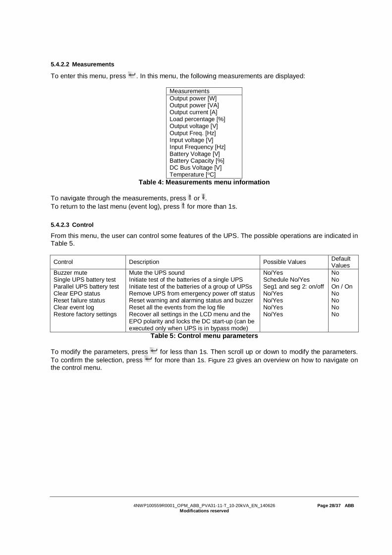
5.4.2.2 Measurements
To enter this menu, press . In this menu, the following measurements are displayed:
MeasurementsOutput power [W]Output power [VA]Output current [A]Load percentage [%]Output voltage [V]Output Freq. [Hz]Input voltage [V]Input Frequency [Hz]Battery Voltage [V]Battery Capacity [%]DC Bus Voltage [V]Temperature [oC]
Table 4: Measurements menu information
To navigate through the measurements, press or .To return to the last menu (event log), press for more than 1s.
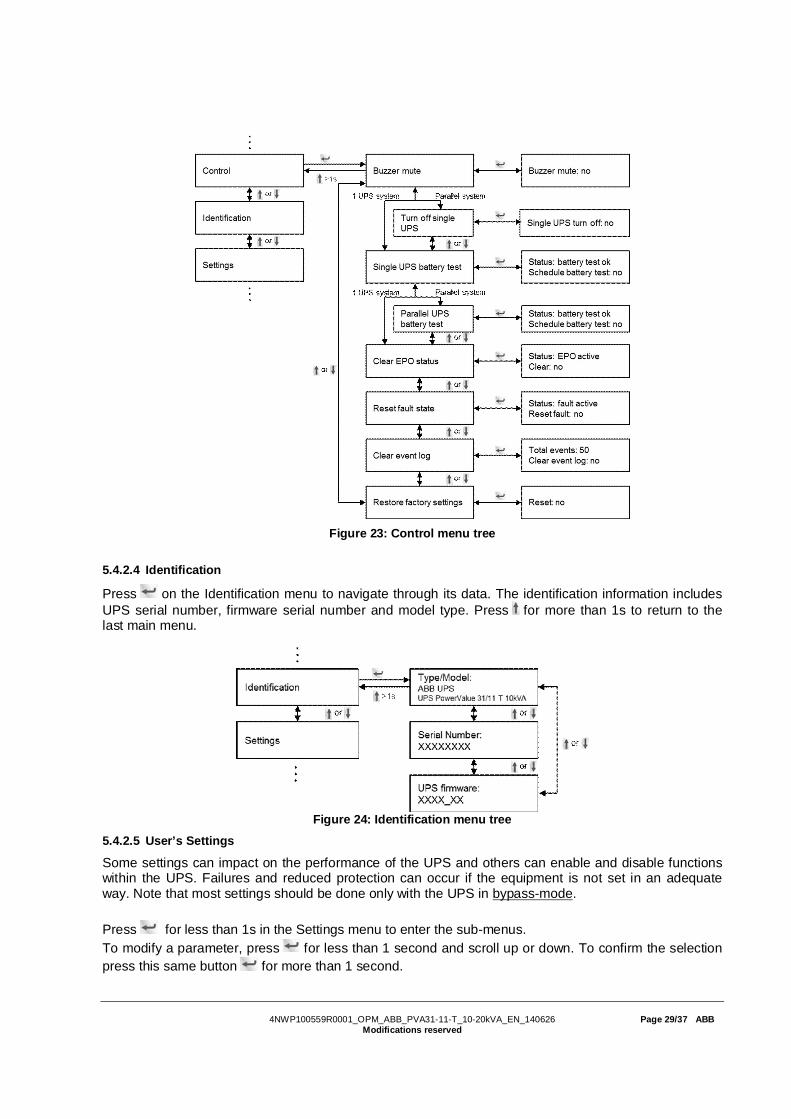
5.4.2.3 Control
From this menu, the user can control some features of the UPS. The possible operations are indicated inTable 5.
Control Description Possible Values DefaultValues
Buzzer muteSingle UPS battery testParallel UPS battery testClear EPO statusReset failure statusClear event logRestore factory settings
Mute the UPS soundInitiate test of the batteries of a single UPSInitiate test of the batteries of a group of UPSsRemove UPS from emergency power off statusReset warning and alarming status and buzzerReset all the events from the log fileRecover all settings in the LCD menu and theEPO polarity and locks the DC start-up (can beexecuted only when UPS is in bypass mode)
No/YesSchedule No/YesSeg1 and seg 2: on/offNo/YesNo/YesNo/YesNo/Yes
NoNoOn / OnNoNoNoNo
Table 5: Control menu parameters
To modify the parameters, press for less than 1s. Then scroll up or down to modify the parameters.To confirm the selection, press for more than 1s. Figure 23 gives an overview on how to navigate onthe control menu.
4NWP100559R0001_OPM_ABB_PVA31-11-T_10-20kVA_EN_140626 Page 29/37 ABBModifications reserved
Figure 23: Control menu tree
5.4.2.4 Identification
Press on the Identification menu to navigate through its data. The identification information includesUPS serial number, firmware serial number and model type. Press for more than 1s to return to thelast main menu.
Figure 24: Identification menu tree
5.4.2.5 User’s Settings
Some settings can impact on the performance of the UPS and others can enable and disable functionswithin the UPS. Failures and reduced protection can occur if the equipment is not set in an adequateway. Note that most settings should be done only with the UPS in bypass-mode.
Press for less than 1s in the Settings menu to enter the sub-menus.To modify a parameter, press for less than 1 second and scroll up or down. To confirm the selectionpress this same button for more than 1 second.

4NWP100559R0001_OPM_ABB_PVA31-11-T_10-20kVA_EN_140626 Page 30/37 ABBModifications reserved
Figure 25: Setting menu tree
If the password is enabled, the user must enter the password USER by pressing the buttons , and. It is used mainly to protect against modifications in the Settings menu. The possible operations are
indicated in Table 6.
Submenu item Description Optional Values Defaultvalue
Language Select menu language English / Chinese EnglishUser password* Protects against settings modifications enabled/disabled disabledAudio alarm Enable/disable alarm sounds enabled/disabled enabledOutput voltage Define local output voltage 200/208/220/230/240V 230V
Output frequency Define local output frequencyautosensing/50/60HzUPS detects the frequencywhen in ‘autosensing’
autosensing
Power strategy** Define the running mode to normal, ECO-mode or high efficiency and converter mode
normal/high efficiency (ECO-mode)/ converter normal
DC start (Cold start) Start the UPS from the batteries (withoutmains power) enabled/disabled enabled
Automatic batterytests period Define the frequency of the battery tests 0-31 days 7 days
Auto restartAfter power outage, the loads restartautomatically when mains power isrecovered.
enabled/disabled enabled
Automatic overloadrestart
The UPS is automatically restarted if itshutdown for overload. enabled/disabled enabled
Auto bypassThe automatic bypass can be disabled forcountries where the power supply is veryunstable. UPS runs only online or on battery.
enabled/disabled disabled
Short circuitclearance
- When enabled, short circuit will last for 4sbefore cutting off the output. If short circuit isremoved during this time, the UPS willcontinue to run normally.- When disabled, short circuit will only last
enabled/disabled disabled

4NWP100559R0001_OPM_ABB_PVA31-11-T_10-20kVA_EN_140626 Page 31/37 ABBModifications reserved
for 100ms before UPS output is cut off.Bypass voltage lowlimit
When the voltage in the bypass is below thislimit, the UPS changes running mode. 176~215V 184V
Bypass voltage highlimit
When the voltage in the bypass is above thislimit, the UPS changes running mode. 245~276V 264V
Bypass frequencylow limit
When the frequency in the bypass is belowthis limit, the UPS changes running mode. 40~49.5 Hz 45 Hz
Bypass frequencyhigh limit
When the frequency in the bypass is abovethis limit, the UPS changes running mode. 50.5~70 Hz 55 Hz
Eco-mode voltagelow limit
When the voltage in the bypass is below thislimit, the UPS changes running mode. 1%~10% 5%
Eco-mode voltagehigh limit
When the voltage in the bypass is above thislimit, the UPS changes running mode. 1%~10% 5%
Eco-mode frequencylow limit
When the frequency in the bypass is belowthis limit, the UPS changes running mode. 1%~10% 5%
Eco-mode frequencyhigh limit
When the frequency in the bypass is abovethis limit, the UPS changes running mode. 1%~10% 5%
External Batterymodules***
Define the number of external batterymodules. 0 - 97 0
Set running time Used to reset the UPS running time for testspurposes.
Day:hour:minute:second0000:0000:00~9999:23:59:59
Runningtime
LCD contrast Change the contrast in the LCD display -5~+5 0Battery remainingtime
When enabled, the battery remaining time isdisplayed in the menu measurements enabled/disabled enabled
Table 6: Settings menu information
**Read Section 5.2, before using ECO-mode or converter function.***Ensure the real battery quantity is same as indicated in the settings not to damage the batteries.
Example: Setting the rated output voltage value (Figure 26).
Figure 26: Setting rated output voltage value

4NWP100559R0001_OPM_ABB_PVA31-11-T_10-20kVA_EN_140626 Page 32/37 ABBModifications reserved
6 COMMUNICATION
A USB and an RS-232 port are available to enable the communication between the UPS and a remotecomputer/station. Only one communication port can be active at a time and the priority is given to theUSB port.Once the communication cable is installed, the power management software can exchange informationwith the UPS. The software collects information from the UPS and indicates the status of the device, thepower quality of the mains and the battery autonomy of the units.In case of a power failure and a predicted shutdown of the UPS due to low battery autonomies, themonitoring system is capable of saving the data in the load and of initiating the shutdown of theequipment connected to the UPS.
6.1 RS-232 port
An RS-232 port is available for UPS monitoring, control and firmware updates. To establish acommunication between the UPS and a computer, connect one end of the serial communication cablethat comes with the UPS to the RS-232 port on the UPS and the other end of the serial cable to the RS-232 port on a computer. The cable pins for the RS-232 communication port are described in Figure 27and in Table 7.
Figure 27: RS-232 Communication Port (DB-9 Connector)
Table 7: RS- 232 Port Pin Assignment
6.2 USB port
The UPS can communicate with an USB-compliant computers. To establish communication between theUPS and a computer, connect the USB cable that comes with the UPS to the USB port on the UPS.Connect the other end of the USB cable to the USB port on a computer. The USB port is compliant withUSB 1.1 protocol.
6.3 Network Management Card (Optional)
PowerValue 31/11 T is equipped with two intelligent slots for optional cards for remote management ofthe UPS through internet / intranet. The accessories below can be installed in any of the intelligent slots.
SNMP Card - SNMP, HTTP and monitoring capabilities through a Web browser interface.AS400 Card - AS400 card for AS400 communication protocol.
Pin Number Signal Description I/O2 TXD Transmit to external device Output3 RXD Receive from external device Input5 GND Ground (tied to chassis) Input
4NWP100559R0001_OPM_ABB_PVA31-11-T_10-20kVA_EN_140626 Page 33/37 ABBModifications reserved
6.3.1 Installing a Serial Network Management Card (optional)
Each UPS has a communication slot for an optional Serial Network Management (SNMP) Card. Afterinstalling an SNMP card, an environmental monitoring probe can be connected to the UPS.
Note: The UPS does not have to be shutdown before installing a communication card.
To install the Network Management Card, go through the following steps:1. Remove the two screws that protect the communication slot of the UPS.2. Insert the SNMP card into the communication slot.3. Screw the SNMP card onto the slot using the screws removed in step 1.
For more information on the SNMP Cards, see the SNMP User's Manual.
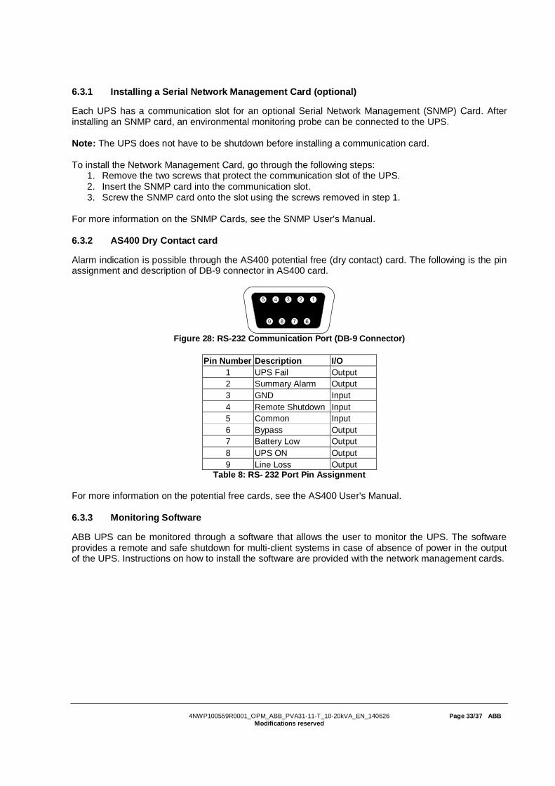
6.3.2 AS400 Dry Contact card
Alarm indication is possible through the AS400 potential free (dry contact) card. The following is the pinassignment and description of DB-9 connector in AS400 card.
Figure 28: RS-232 Communication Port (DB-9 Connector)
Pin Number Description I/O1 UPS Fail Output2 Summary Alarm Output3 GND Input4 Remote Shutdown Input5 Common Input6 Bypass Output7 Battery Low Output8 UPS ON Output9 Line Loss Output
Table 8: RS- 232 Port Pin Assignment
For more information on the potential free cards, see the AS400 User's Manual.
6.3.3 Monitoring Software
ABB UPS can be monitored through a software that allows the user to monitor the UPS. The softwareprovides a remote and safe shutdown for multi-client systems in case of absence of power in the outputof the UPS. Instructions on how to install the software are provided with the network management cards.
4NWP100559R0001_OPM_ABB_PVA31-11-T_10-20kVA_EN_140626 Page 34/37 ABBModifications reserved
7 TROUBLESHOOTING
7.1 Fault identification and rectification
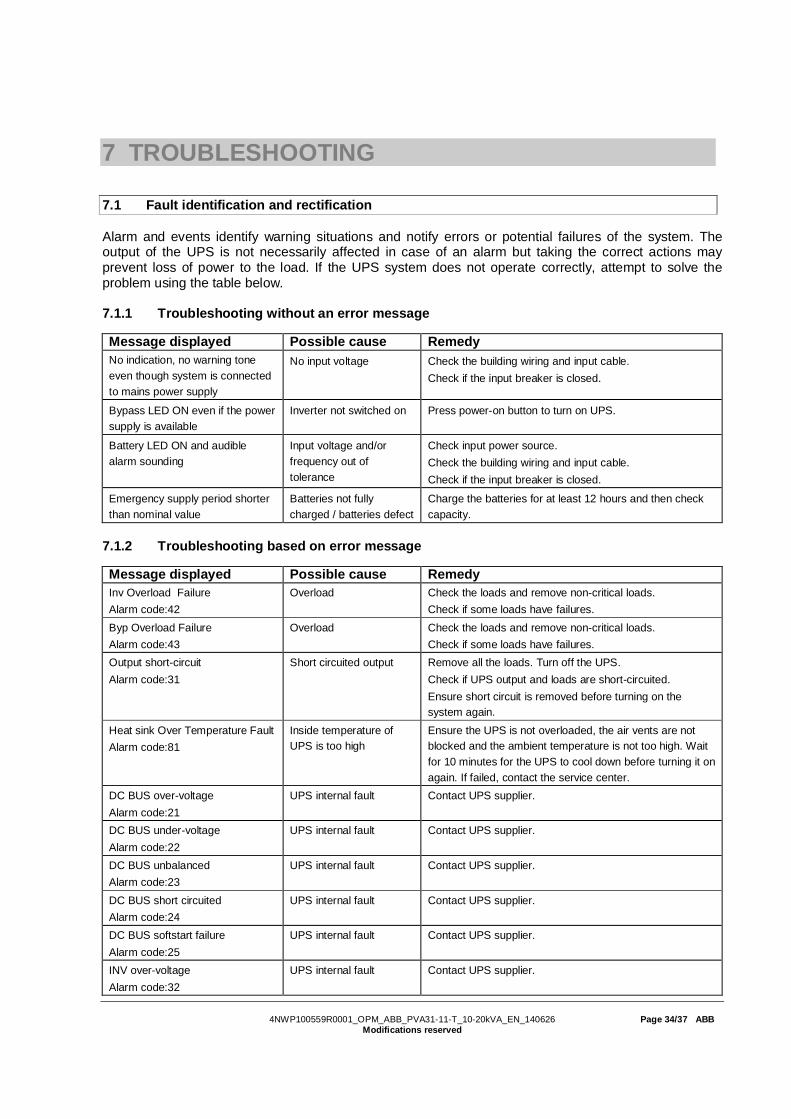
Alarm and events identify warning situations and notify errors or potential failures of the system. Theoutput of the UPS is not necessarily affected in case of an alarm but taking the correct actions mayprevent loss of power to the load. If the UPS system does not operate correctly, attempt to solve theproblem using the table below.
7.1.1 Troubleshooting without an error message
Message displayed Possible cause RemedyNo indication, no warning toneeven though system is connectedto mains power supply
No input voltage Check the building wiring and input cable.Check if the input breaker is closed.
Bypass LED ON even if the powersupply is available
Inverter not switched on Press power-on button to turn on UPS.
Battery LED ON and audiblealarm sounding
Input voltage and/orfrequency out oftolerance
Check input power source.Check the building wiring and input cable.Check if the input breaker is closed.
Emergency supply period shorterthan nominal value
Batteries not fullycharged / batteries defect
Charge the batteries for at least 12 hours and then checkcapacity.
7.1.2 Troubleshooting based on error message
Message displayed Possible cause RemedyInv Overload FailureAlarm code:42
Overload Check the loads and remove non-critical loads.Check if some loads have failures.
Byp Overload FailureAlarm code:43
Overload Check the loads and remove non-critical loads.Check if some loads have failures.
Output short-circuitAlarm code:31
Short circuited output Remove all the loads. Turn off the UPS.Check if UPS output and loads are short-circuited.Ensure short circuit is removed before turning on thesystem again.
Heat sink Over Temperature FaultAlarm code:81
Inside temperature ofUPS is too high
Ensure the UPS is not overloaded, the air vents are notblocked and the ambient temperature is not too high. Waitfor 10 minutes for the UPS to cool down before turning it onagain. If failed, contact the service center.
DC BUS over-voltageAlarm code:21
UPS internal fault Contact UPS supplier.
DC BUS under-voltageAlarm code:22
UPS internal fault Contact UPS supplier.
DC BUS unbalancedAlarm code:23
UPS internal fault Contact UPS supplier.
DC BUS short circuitedAlarm code:24
UPS internal fault Contact UPS supplier.
DC BUS softstart failureAlarm code:25
UPS internal fault Contact UPS supplier.
INV over-voltageAlarm code:32
UPS internal fault Contact UPS supplier.
4NWP100559R0001_OPM_ABB_PVA31-11-T_10-20kVA_EN_140626 Page 35/37 ABBModifications reserved
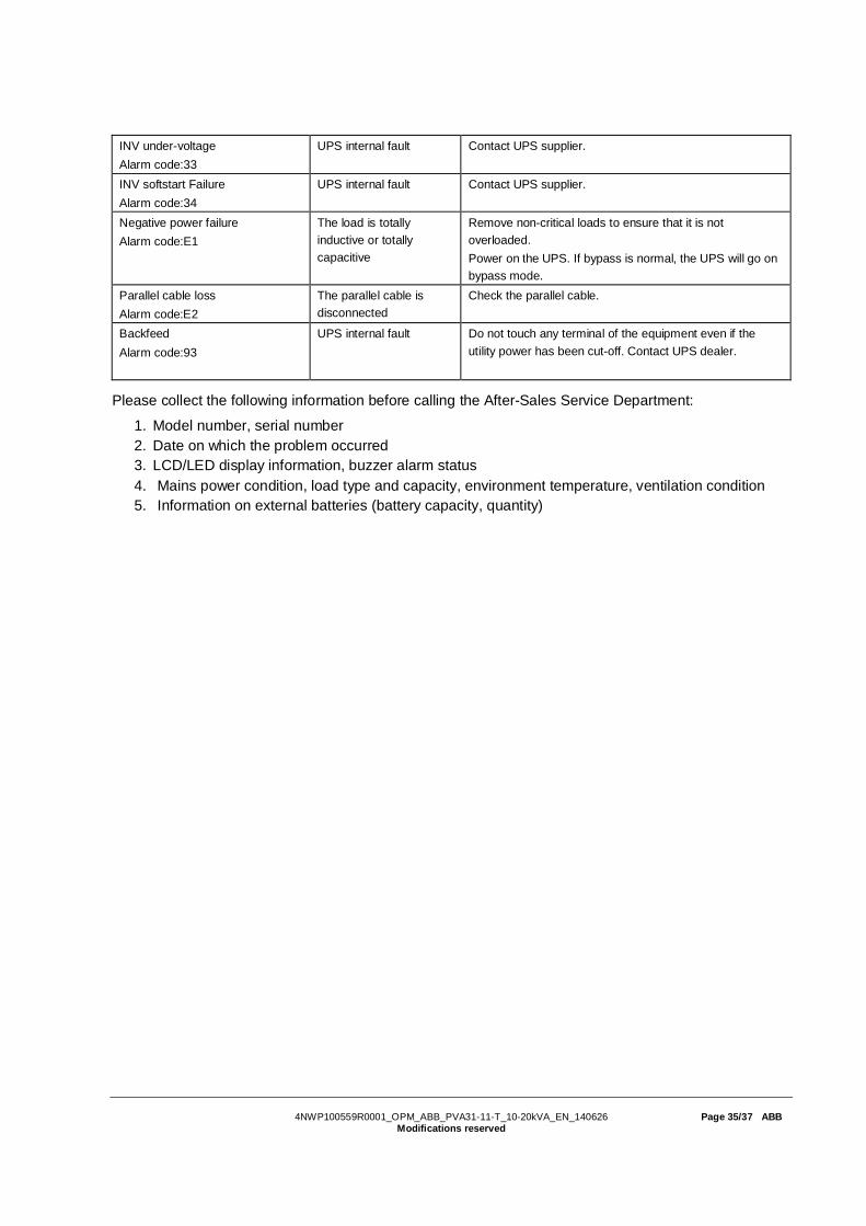
INV under-voltageAlarm code:33
UPS internal fault Contact UPS supplier.
INV softstart FailureAlarm code:34
UPS internal fault Contact UPS supplier.
Negative power failureAlarm code:E1
The load is totallyinductive or totallycapacitive
Remove non-critical loads to ensure that it is notoverloaded.Power on the UPS. If bypass is normal, the UPS will go onbypass mode.
Parallel cable lossAlarm code:E2
The parallel cable isdisconnected
Check the parallel cable.
BackfeedAlarm code:93
UPS internal fault Do not touch any terminal of the equipment even if theutility power has been cut-off. Contact UPS dealer.
Please collect the following information before calling the After-Sales Service Department:
1. Model number, serial number2. Date on which the problem occurred3. LCD/LED display information, buzzer alarm status4. Mains power condition, load type and capacity, environment temperature, ventilation condition5. Information on external batteries (battery capacity, quantity)

4NWP100559R0001_OPM_ABB_PVA31-11-T_10-20kVA_EN_140626 Page 36/37 ABBModifications reserved
8 TECHNICAL SPECIFICATION
GENERAL DATA 10 kVA 10 kVA5 min
10kVA16 min 20 kVA 20kVA
5 minOutput rated power [W] 9 kW 18 kWOutput power factor 0.9 0.9Topology True online double conversion True online double conversionParallel configuration Up to 4 units Up to 4 unitsInbuilt batteries No Yes Yes No YesINPUT
Nominal input voltage 1ph + N: 220 / 230 / 240 VAC3ph + N: 380 / 397 / 415 VAC
Input voltage tolerance 1ph + N: 110-276 VAC
3ph + N: 190-486 VAC
Input current THD <5% linear load, <7% non-linear loadFrequency range 45-55Hz for 50Hz systems / 55-65Hz for 60Hz systemFrequency tolerance ±0.05 HzPower factor ≥0.99OUTPUTRated output voltage 220 / 230 / 240 VAC
Voltage tolerance ±2%Voltage distortion ≤2% linear load, ≤5% non-linear loadOverload capability(linear load)
5 min: 105%~110%, 1 min: 110%~130%,10 s: 130%~150%, 2s: >150%
Nominal frequency 50 or 60 Hz ± 0.1 HzCrest factor 3:1EFFICIENCYAC-AC Up to 93%In eco-mode Up to 97%ENVIRONMENTProtection rating IP 20Storage temperature -15 – +60°C for UPS, 0~35°C for batteryOperating temperature 0 – 40°CRelative humidity 0-95% (Non-condensing)Altitude (above sealevel) 1000m without de-rating
BATTERIESType VRLA, vented lead-acidNumber of batteries - 1x24 2 x 24 - 2 x 24Battery capacity - 9 Ah 9 Ah - 9 AhCharging current 4 A 4 A 4 A 4 A 4ARecharge time 3h to 90% 8h to 90% 8h to 90%COMMUNICATIONSUser interface LCD displayCommunication cards(option) Network interface (SNMP card), dry- contact card (AS400)
STANDARDSSafety IEC/EN 62040-1EMC IEC/EN 62040ROHS EN50581:2012Performance IEC/EN 62040-3Manufacturing ISO 9001:2008, ISO 14001:2004WEIGHT, DIMENSIONSWeight 56 kg 117 kg 177 kg 66 kg 187 kgDimensions WxHxD 350*890*712 350*890*712 350*890*712 350*890*712 350*890*172*Technical specifications are subject to change without notice

4NWP100559R0001_OPM_ABB_PVA31-11-T_10-20kVA_EN_140626 Page 37/37 ABBModifications reserved