pr -705/715 spectrascan instruction manual · pr -705/715 spectrascan instruction manual ... the pr...
TRANSCRIPT

PR-705/715 SpectraScan
Instruction Manual
PPHHOOTTOO RREESSEEAARRCCHH,, IINNCC..
PHOTO RESEARCH
, Inc. 9731 Topanga Canyon Place Chatsworth, CA 91311-4135 Phone: (818) 341-5151 FAX: (818) 341-7070 Home Page: www.photoresearch.com

Notice The information contained in this document is subject to change without notice. If there are any questions pertaining to the use of this system, contact PHOTO RESEARCH. PHOTO RESEARCH shall not be liable for errors contained herein or for incidental consequential damages in connection with the furnishing, performance, or use of this system. This document contains proprietary information that is protected by copyright. All rights are reserved worldwide. No part of this document may be reproduced photographically, electronically or by any other means without the express written permission of the President of PHOTO RESEARCH. Patents Pending. 1999 by PHOTO RESEARCH, Inc. All right reserved worldwide.
PR is a registered trademark of PHOTO RESEARCH, Inc. PHOTO RESEARCH, Inc. is a registered trademark of PHOTO RESEARCH, Inc. Pritchard is a registered trademark of PHOTO RESEARCH, Inc. SpectraScan is a registered trademark of PHOTO RESEARCH, Inc. Automatic Adaptive Sensitivity is a registered trademark of PHOTO RESEARCH, Inc.
Document # 9903-0006-40 Rev. C Printed in Chatsworth, California, U.S.A.

Customer Support PHOTO RESEARCH, Inc. has support services available to users in case of problems using the PR-705 / 715. PHOTO RESEARCH, Inc. personnel are available from 8:00 AM to 4:30 PM (Pacific Time) Monday through Friday, except legal holidays, to aid in technical support. Call (818) 341-5151, FAX: (818) 341-7070 or e-mail: [email protected] for technical support. If calling, please have the following information ready: • Instrument Model • Instrument Serial Number • This manual • Any printed data you feel might aid in
resolving the problem such as test data.

Table of Contents
PR-705 Instruction Manual i
Table of Contents
CHAPTER 1 CHAPTER 1 -- THEORY OF OPERATION...1-1
Description ............................................................................. 1-1
System Components .............................................................. 1-2
Measurement Sequences ....................................................... 1-3
CHAPTER 2 CHAPTER 2 -- GETTING STARTED............2-1
Hardware Setup..................................................................... 2-1
Connectors ............................................................................. 2-3
Hardware Set-up Procedure................................................. 2-5
CHAPTER 3 CHAPTER 3 -- MAKING A MEASUREMENT.3-1
Overview................................................................................. 3-1
Focusing and Aligning the PR-705....................................... 3-1
Selecting Setup Parameters .................................................. 3-4
Selecting an Aperture............................................................ 3-5
Starting a Measurement........................................................ 3-6
CHAPTER 4 CHAPTER 4 -- PR-705 KEYS.......................4-1
LITE ....................................................................................... 4-2

Table of Contents
PR-705 Instruction Manual ii
ALT.........................................................................................4-2
UP ARROW (ss) ....................................................................4-3
DOWN ARROW (tt) ............................................................4-3
BACK / FRWD ......................................................................4-4
ENTR ......................................................................................4-4
CALC / PRNT........................................................................4-5
STOP / MEAS ........................................................................4-6
CHAPTER 5 CHAPTER 5 -- PR-705 SCREENS ...............5-1
Overview.................................................................................5-1
Screen Icons............................................................................5-1
Screen Navigation ..................................................................5-3
Calculated Values ..................................................................5-6
Screen Descriptions ...............................................................5-8
Setup Screen #1 – Accessory Selection.................................5-8
Setup Screen #2 – Display Options, Aperture Selection and Photometric Units Selection..................................................5-9
Setup Screen #3 – Detector Exposure Time, Capture Method and Cycles to Average Selection .........................................5-12
Setup Screen #4 – Calculation Mode, Trigger Method and File Operations.....................................................................5-14
Setup Screen #5 – View Shutter, CIE Observer Selection5-22
Table of Contents
PR-705 Instruction Manual iii
Print Setup ........................................................................... 5-24
Date, Time Setup ................................................................. 5-31
Save, Load Setup ................................................................. 5-32
CHAPTER 6 CHAPTER 6 -- MAINTENANCE ...................6-1
Cleaning Lenses ..................................................................... 6-1
Re-calibration ........................................................................ 6-2
Factory Repair....................................................................... 6-2
In-Warranty Repair .............................................................. 6-2
Returning an Instrument ...................................................... 6-3
GLOSSARY OF TERMS .................................. A
CIE.............................................................................................A
CIE Chromaticity Coordinates ...............................................A
CIELAB.....................................................................................A
Correlated Color Temperature (CCT) ...................................B
Filter Photometer......................................................................B
Hue.............................................................................................B
Illuminance................................................................................C
Lambertian surface ..................................................................C
Luminance.................................................................................C

Table of Contents
PR-705 Instruction Manual iv
Luminous Efficiency Function................................................ D
Luminous Flux ......................................................................... D
Luminous Intensity (Candlepower)........................................ D
Metamerism.............................................................................. D
Photometer ................................................................................E
Photometry ................................................................................E
Saturation ..................................................................................E
Spectroradiometer ....................................................................E
Standard Illuminant .................................................................F
Standard Observer Functions..................................................F
Steradian....................................................................................F
Supplemental Observer Functions ..........................................F
Tristimulus Values................................................................... G
Visible Light ............................................................................. G
APPENDIX A APPENDIX A -- REMOTE MODE OPERATIONS................... A-1
APPENDIX B APPENDIX B -- GPIB-232 INTERFACE ..... B-1
APPENDIX C APPENDIX C -- IS-700 INTEGRATING SPHERE................... C-1

Table of Contents
PR-705 Instruction Manual v
APPENDIX D APPENDIX D -- ERROR CODES ................D-1
APPENDIX E APPENDIX E -- EXTERNAL TRIGGER....... E-1
APPENDIX F APPENDIX F -- CR-55 COSINE RECEPTOR......................... F-1
APPENDIX G APPENDIX G -- SPECIFICATIONS.............G-1
APPENDIX H APPENDIX H -- PR-705 / 715 BATTERY PACK.....................H-1
APPENDIX I APPENDIX I -- FP-55 FIBER PROBE ...........I-1
APPENDIX JAPPENDIX J - LR-55 LED RECEPTOR......J-1


Chapter 1 - Theory of Operation
PR-705 Instruction Manual 1-1
Chapter 1 Chapter 1 -- Theory of Operation
Description The PR-705 is a parallel acquisition (fast-scan) spectroradiometer and has a fixed polychromator (diffraction grating), which disperses the majority of the visible spectrum (380 nm to 780 nm for the PR-705, 380 nm to 1068 nm for the PR-715) onto a thermoelectrically cooled, 256 silicon photodiode array detector. Each of the 256 detectors measures a specific color (wavelength), and the entire spectrum is measured simultaneously. The photodiode array is scanned electronically and the entire scan can be done in as little as a fraction of a second. By thermo-electrically cooling the detector, changing the detectors exposure time (Adaptive Sensitivity®) and digitally integrating many scans, the sensitivity and dynamic range is optimized for the source being measured.
VViieewweerr
OObbjjeeccttiivvee LLeennss
Chapter 1
PPrriittcchhaarrdd MMiirrrroorr
DDiiffffrraaccttiioonn GGrraattiinngg
225566 eelleemmeenntt DDeetteeccttoorr
PR-705 Block Diagram

Chapter 1 - Theory of Operation
PR-705 Operating Manual 1-2
System Components
Hardware A 486 “computer on chip” controls the PR-705, which is responsible for controlling and or monitoring all motors, communications, measurements and calculations. Silicon memory circuits are used as the “hard drive” for the instrument and, like a traditional hard drive, does not require battery back-up.
Communications The PR-705 / 715 is equipped with two interfaces to handle communications to the outside world. A 9 pin, sub-d connector is provided for RS-232C communications, and a Centronics parallel 25-pin connector is available for connecting to a standard DOS printer. See the “Connectors” sections for complete details.
Data Storage Following a measurement, data can be stored as binary or text files to the built-in, 1.44 Mbytes floppy disk drive.
Custom Applications Each PR-705 / 715 is equipped with Remote Mode programming capabilities. Remote Mode programming enables the user to control the PR-705 / 715 from an application program by sending commands and receiving reports in ASCII (text) format.

Chapter 1 - Theory of Operation
PR-705 Instruction Manual 1-3
This provides a powerful tool for Automated Test Equipment (ATE) applications or any task that requires specialized measurement procedures.
SpectraWin Software An optional operating program, SpectraWin, is available for control and measurements with the PR-705 / 715 from a Windows (’95, ’98, NT) based application. SpectraWin utilizes a full Graphical Users Interface (GUI), displays measured results using full color graphs, has numerous pre-canned measurement routines such as reflectance and transmittance and like other Windows based programs, allows cutting and pasting of graphics and or text to other programs (e.g. Microsoft Word and Excel). Additionally, an option to SpectraWin allows complete on-site re-calibration of the PR-705 / 715. Please call Photo Research for more information.
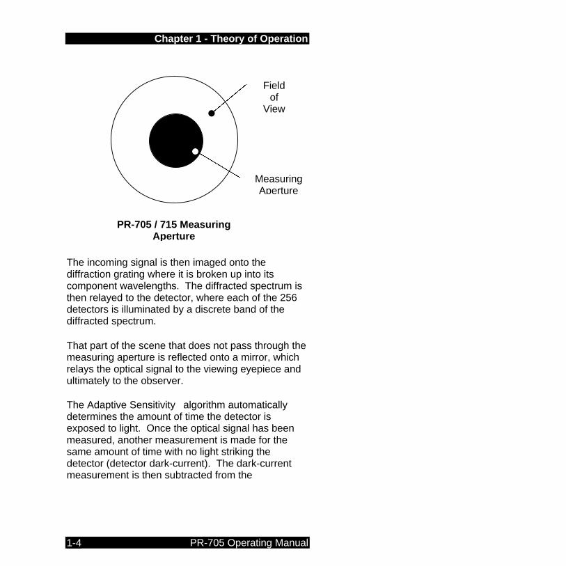
Measurement Sequences During a measurement, the optical signal enters the collection optics (the default collection optics for the PR-705 is a 55 mm variable focus objective lens – the MS-55). The objective lens then images the signal on the Pritchard Mirror measuring field (up to six available on a single instrument) which also serves as the entrance slit for the spectrometer. The measuring aperture appears as a black area in the center of the field of view.
Chapter 1 - Theory of Operation
PR-705 Operating Manual 1-4
The incoming signal is then imaged onto the diffraction grating where it is broken up into its component wavelengths. The diffracted spectrum is then relayed to the detector, where each of the 256 detectors is illuminated by a discrete band of the diffracted spectrum. That part of the scene that does not pass through the measuring aperture is reflected onto a mirror, which relays the optical signal to the viewing eyepiece and ultimately to the observer. The Adaptive Sensitivity algorithm automatically determines the amount of time the detector is exposed to light. Once the optical signal has been measured, another measurement is made for the same amount of time with no light striking the detector (detector dark-current). The dark-current measurement is then subtracted from the
Field of
View
Measuring Aperture
PR-705 / 715 Measuring Aperture
Chapter 1 - Theory of Operation
PR-705 Instruction Manual 1-5
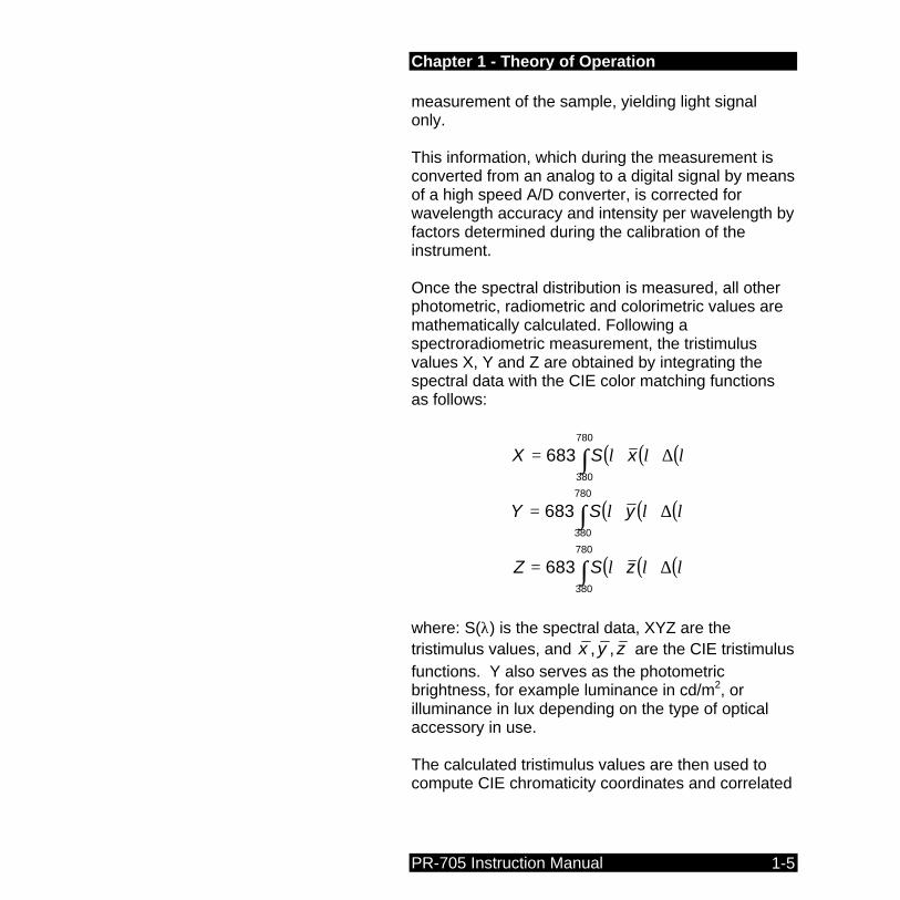
measurement of the sample, yielding light signal only. This information, which during the measurement is converted from an analog to a digital signal by means of a high speed A/D converter, is corrected for wavelength accuracy and intensity per wavelength by factors determined during the calibration of the instrument. Once the spectral distribution is measured, all other photometric, radiometric and colorimetric values are mathematically calculated. Following a spectroradiometric measurement, the tristimulus values X, Y and Z are obtained by integrating the spectral data with the CIE color matching functions as follows:
( ) ( ) ( )∫ ∆=780
380
683 λλλ xSX
( ) ( ) ( )∫ ∆=780
380
683 λλλ ySY
( ) ( ) ( )∫ ∆=780
380
683 λλλ zSZ
where: S(λ) is the spectral data, XYZ are the tristimulus values, and zyx ,, are the CIE tristimulus functions. Y also serves as the photometric brightness, for example luminance in cd/m2, or illuminance in lux depending on the type of optical accessory in use. The calculated tristimulus values are then used to compute CIE chromaticity coordinates and correlated
Chapter 1 - Theory of Operation
PR-705 Operating Manual 1-6
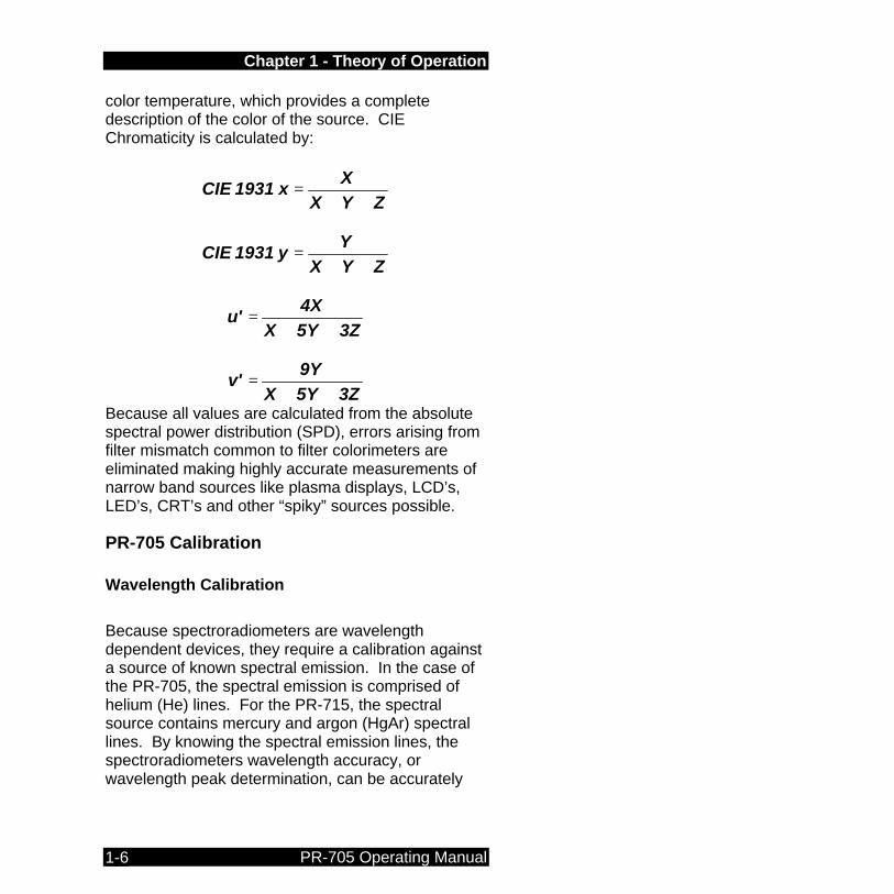
color temperature, which provides a complete description of the color of the source. CIE Chromaticity is calculated by:
ZYXX
x 1931 CIE++
=
ZYXY
y1931 CIE++
=
3Z5YX4X
u'++
=
3Z5YX9Y
v'++
=
Because all values are calculated from the absolute spectral power distribution (SPD), errors arising from filter mismatch common to filter colorimeters are eliminated making highly accurate measurements of narrow band sources like plasma displays, LCD’s, LED’s, CRT’s and other “spiky” sources possible.
PR-705 Calibration Wavelength Calibration
Because spectroradiometers are wavelength dependent devices, they require a calibration against a source of known spectral emission. In the case of the PR-705, the spectral emission is comprised of helium (He) lines. For the PR-715, the spectral source contains mercury and argon (HgAr) spectral lines. By knowing the spectral emission lines, the spectroradiometers wavelength accuracy, or wavelength peak determination, can be accurately

Chapter 1 - Theory of Operation
PR-705 Instruction Manual 1-7
calibrated. The wavelength calibration is the first phase in the calibration process. Intensity Calibration
The second phase of a spectroradiometer calibration consists of a calibration for intensity versus wavelength. The standards used for this calibration are the same types used for photometer calibrations such as an integrating sphere source (like the Photo Research Model LRS-455 or LRS-462), or irradiance lamp standard in combination with a calibrated reflectance standard. Spectral standards are calibrated for intensity versus wavelength (spectral intensity calibration). The PR-705 measures the spectral standard, and factors are determined for each wavelength based on the measured value and published data for the standard. This calibration insures that whatever type of spectral sample, the result is an accurate spectral power distribution (SPD).


Chapter 2 - Getting Started
PR-705 Instruction Manual 2-1
Chapter 2 Chapter 2 -- Getting Started
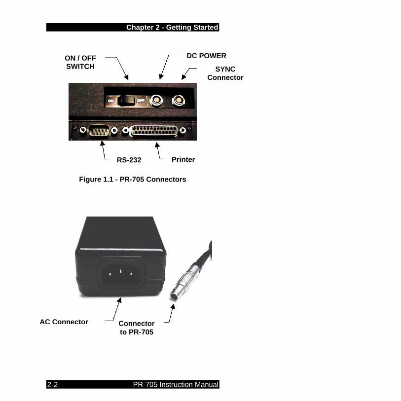
Hardware Setup The PR-705 / 715 SpectraScan Spectroradiometer is supplied with an AC Adapter Power Supply and RS-232 cable. The AC Adapter can be used for AC input voltages from 90 to 250 volts. The AC frequency range is from 50 to 60 Hertz (cycles per second). The RS-232 cable is used to connect the PR-705 (PR-715) to a remote host (PC) for using the optional SpectraWin software package, or to transfer measured data reports from the PR-705 to a PX following a measurement. The Printer connector supports a standard DOS or Windows Centronics parallel printer. Use this to print measurement results directly from the PR-705 (ASCII text data only - no graphics). The SYNC Connector is used to make measurements synchronized to an external source. See Appendix E for further details on PR-705 / 715 externally triggered measurements.
Chapter 2 - Getting Started
PR-705 Instruction Manual 2-2
Figure 1.1 - PR-705 Connectors
Connector to PR-705
AC Connector
RS-232 Printer
ON / OFF SWITCH
DC POWER
SYNC Connector
Chapter 2 - Getting Started
PR-705 Instruction Manual 2-3
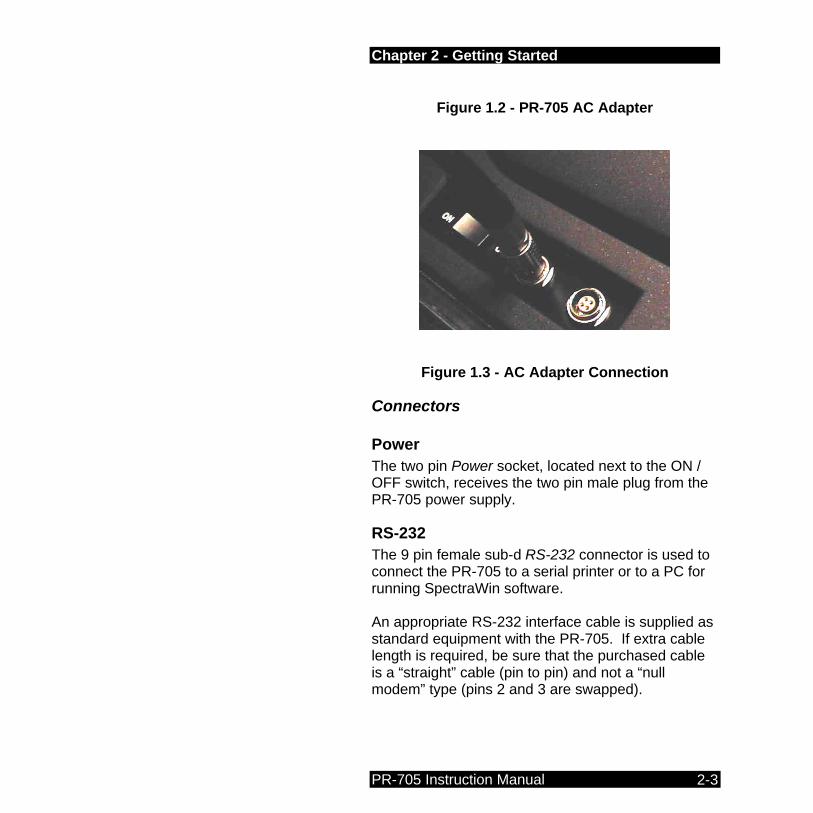
Figure 1.2 - PR-705 AC Adapter
Figure 1.3 - AC Adapter Connection
Connectors
Power The two pin Power socket, located next to the ON / OFF switch, receives the two pin male plug from the PR-705 power supply.
RS-232 The 9 pin female sub-d RS-232 connector is used to connect the PR-705 to a serial printer or to a PC for running SpectraWin software.
An appropriate RS-232 interface cable is supplied as standard equipment with the PR-705. If extra cable length is required, be sure that the purchased cable is a “straight” cable (pin to pin) and not a “null modem” type (pins 2 and 3 are swapped).

Chapter 2 - Getting Started
PR-705 Instruction Manual 2-4
Handshaking During operation, the PR-705 / 715 uses the RTS and CTS lines for communications handshaking. Therefore, if using a terminal emulator such as Microsoft Windows HyperTerminal, configure the Flow Control to Hardware.
RS-232 Interface Pin Assignments
PIN Description Abbreviation
1 Data Carrier Detect DCD
2 Receive Data RX
3 Send Data TX
4 Data Terminal Ready DTR
5 Signal Ground
6 Data Set Ready DSR
7 Request To Send RTS
8 Clear To Send CTS
9 Ring Indicator RI
SYNC See Appendix E for more details.
Printer This is a standard Centronics parallel printer connector; the same as found on most desktop and laptop Microsoft DOS or Microsoft Windows based PC’s

Chapter 2 - Getting Started
PR-705 Instruction Manual 2-5
Hardware Set-up Procedure STEP 1 - Make sure the ON / OFF switch is set to
OFF.
STEP 2 - Insert the receptacle on the AC Power Cord into the AC Adapter Power Supply jack. Insert the other end of the AC cord into a suitable wall outlet.
STEP 3 - Carefully insert the two-pin plug from the PR-705 power supply into the two-pin socket on the PR-705. This is a keyed connector. Rotate the connector
until the orientation keys align, then gently insert the connector until it “clicks”. To remove the connector, pull back on the spring loaded knurled ring and gently pull.
STEP 4 - (OPTIONAL) – Insert an IBM formatted
3.5" floppy disk in the disk drive located on the side opposite the connectors.
Note: Do not use any other power supply except the one supplied by PHOTO RESEARCH to power the PR-705. Irreparable damage could result

Chapter 2 - Getting Started
PR-705 Instruction Manual 2-6
Note: If a floppy disk with a valid Setup file located on the root directory, the PR-705/715 will utilize the setup parameters on the disk.
STEP 5 - Toggle the ON / OFF Switch to the ON position.
The PR-705 will perform a self-test sequence and when finished, will display a screen similar to the following:
This screen may be exited by pressing the FRWD key at any time. Warning: If a measurement is made before the
PR-705 / 715 detector is sufficiently stabilized, inaccurate results may occur.
STEP 6 - Once the detector temperature is
stabilized, a screen similar to the following screen appears.
PR-705 Press MEAS, or FRWD for setup options. Dec 10 1997 11:53:31
Detector Stabilizing 10 min
Next calibration due Dec 09 1999

Chapter 2 - Getting Started
PR-705 Instruction Manual 2-7
STEP 7 - Press the FRWD key to change
instrument set-up parameters, or press the MEAS key to make a measurement with the current parameters (see Chapter 3, Making Measurements).

Chapter 3 - Making a Measurement
PR-705 Instruction Manual 3-1
Chapter 3 Chapter 3 -- Making a Measurement
Overview In general, a PR-705 measurement consists of a few basic steps. These steps include: • Focusing and aligning the instrument
• Selecting the setup parameters through the
software and
• Executing the measurement. The remainder of this describes the steps required to make a successful PR-705 measurement.
Focusing and Aligning the PR-705 To insure measurements made with the PR-705 are as accurate as possible, it is important to properly align and focus the instrument onto the target.
Focusing Proper focus of the PR-705 is essential to insuring accurate measurement results. If the instrument is not focused correctly, a parallax condition will exist resulting in improper alignment of the measurement aperture on the target.
Chapter 3 - Making a Measurement
PR-705 Instruction Manual 3-2
Focusing Procedure
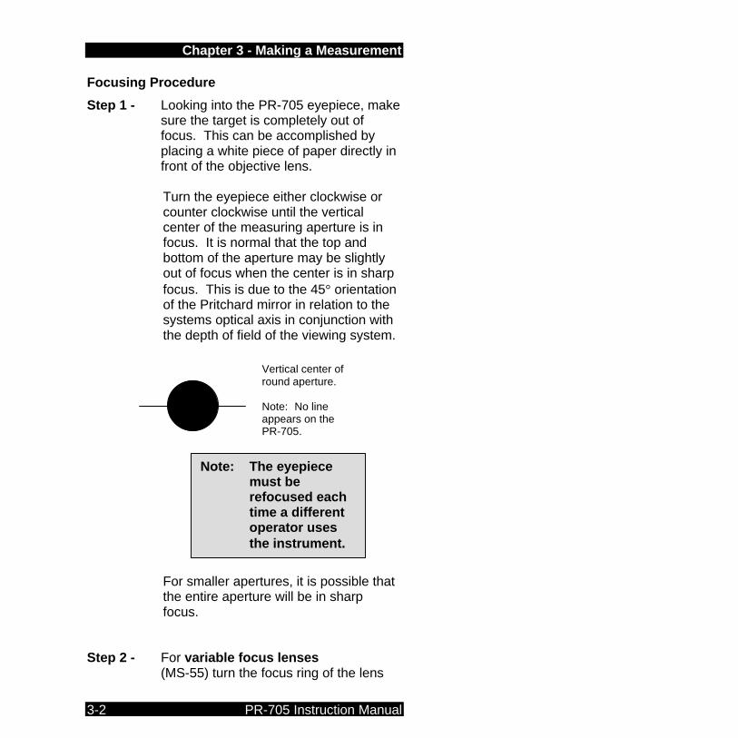
Step 1 - Looking into the PR-705 eyepiece, make sure the target is completely out of focus. This can be accomplished by placing a white piece of paper directly in front of the objective lens. Turn the eyepiece either clockwise or counter clockwise until the vertical center of the measuring aperture is in focus. It is normal that the top and bottom of the aperture may be slightly out of focus when the center is in sharp focus. This is due to the 45° orientation of the Pritchard mirror in relation to the systems optical axis in conjunction with the depth of field of the viewing system.
For smaller apertures, it is possible that the entire aperture will be in sharp focus.
Step 2 - For variable focus lenses
(MS-55) turn the focus ring of the lens
Vertical center of round aperture. Note: No line appears on the PR-705.
Note: The eyepiece must be refocused each time a different operator uses the instrument.
Chapter 3 - Making a Measurement
PR-705 Instruction Manual 3-3
until the target is in sharp focus in the vertical center of the field of view.
Step 3 - For fixed focus lenses (MS-1X, MS-77,
and MS-5X) move either the PR-705 or target until the horizontal center of the field of view is in sharp focus.
Alignment When using an objective lens, attention must be paid to the proper alignment of the measuring aperture on the target. Improper aperture alignment will result in inaccurate results.
Alignment Procedure
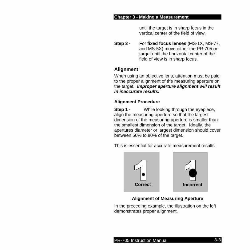
Step 1 - While looking through the eyepiece, align the measuring aperture so that the largest dimension of the measuring aperture is smaller than the smallest dimension of the target. Ideally, the apertures diameter or largest dimension should cover between 50% to 80% of the target. This is essential for accurate measurement results.
In the preceding example, the illustration on the left demonstrates proper alignment.
Alignment of Measuring Aperture on the Target
Correct Incorrect

Chapter 3 - Making a Measurement
PR-705 Instruction Manual 3-4
Refocus the objective lens on the target if necessary after aligning the PR-705. It is not necessary to refocus the eyepiece.
Selecting Setup Parameters All measurement setup parameters including hardware setup, data display selection and printing options are accessed from one of 8 setup screens. Screen descriptions are detailed in Chapter 5 – PR-705 Screens. Following are procedures covering selection of three primary hardware attributes: optical accessory selection, Aperture selection and Display options.
Selecting an Optical Accessory Step 1 - Press the FRWD until Setup Screen #1
appears.
Step 2 - Press the s or t key until the > symbol is aligned to the left of the Lens: field.
Step 3 - Press the ENTR key to cause the field to the right of Lens: to begin blinking.
Step 4 - Press the s or t key to scroll through calibrated Lens: choices.
Step 5 - Press ENTR to accept the currently displayed Lens:.
Step 6 - Repeat Steps 2 – 5 for the Add1: and or Add2: fields.
Chapter 3 - Making a Measurement
PR-705 Instruction Manual 3-5
Selecting an Aperture The PR-705 can be equipped with as many as six apertures (measuring fields). If your system is supplied with more one aperture (standard equipment), use the following procedure to select the aperture to be used for the next measurement. Step 1 - Press the FRWD key until Setup Screen
#2 appears.
Step 2 - Press the s or t key until the > symbol is to the left of Aperture:.
Step 3 - Press the ENTR key to cause the field to the right of Aperture: to begin blinking.
Step 4 - Press the s or t key until the aperture of choice appears.
Step 5 - Press the ENTR key to accept the displayed selection.
Selecting a Data Display Option Following a PR-705 measurement, the data can be displayed is one of several formats. These display options are described in detail in Chapter 5 – PR-705 screens. The following procedure describes the steps required to select a data display option. Step 1 - Press the FRWD until Setup Screen #2
appears.
Step 2 - Press the s or t key until the > symbol is to the lift of Display:.

Chapter 3 - Making a Measurement
PR-705 Instruction Manual 3-6
Step 3 - Press the ENTR key to cause the field to the right of Display: to begin blinking.
Step 4 - Press the s or t key until the display option of choice appears.
Step 5 - Press the ENTR key to accept the displayed selection.
Redisplaying Data Use the following procedure to re-display calculated values other than those displayed following a measurement. For example, if Yxy, CCT was displayed following a measurement, and now Yxy, u’v’ is required: Step - After a measurement, use Steps 1-5 from
the preceding section to select a Display type (Yxy,u’v’ for example).
Step - Press the Alt key.
Step - Press the CALC key. The measured values are re-displayed. This becomes the default for future measurements.
Starting a Measurement After hardware and display options have been selected, and if the symbol appears in the upper right hand corner of the PR-705 display, a measurement may now commence. To make a measurement: Step 1 - Press the MEAS key to begin the
measurement.
Chapter 3 - Making a Measurement
PR-705 Instruction Manual 3-7
Step 2 - At the completion of the measurement, the measured data is displayed according to the current Display selection.

Chapter 4 - PR-705 Keys
PR-705 Instruction Manual 4-1
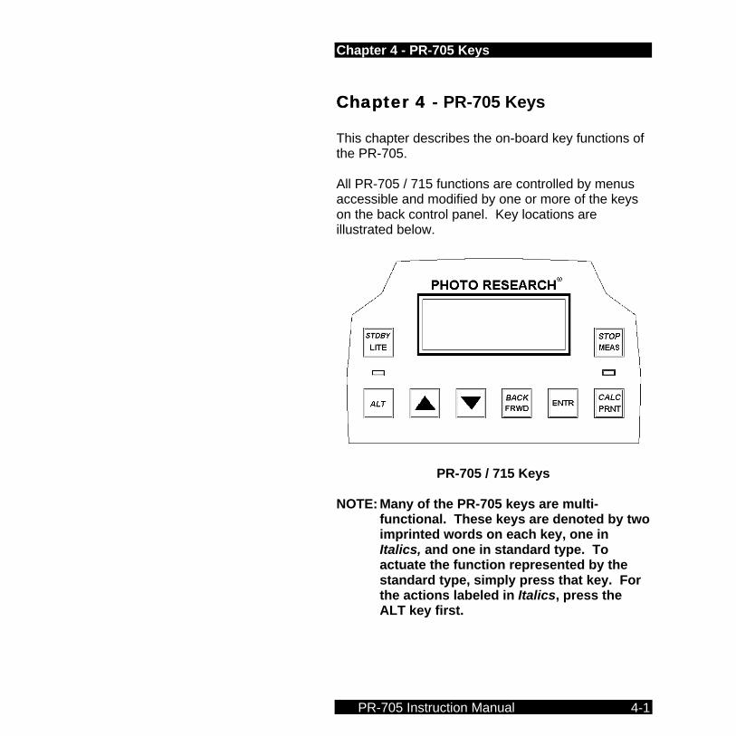
Chapter 4 Chapter 4 -- PR-705 Keys This chapter describes the on-board key functions of the PR-705. All PR-705 / 715 functions are controlled by menus accessible and modified by one or more of the keys on the back control panel. Key locations are illustrated below.
PR-705 / 715 Keys NOTE: Many of the PR-705 keys are multi-
functional. These keys are denoted by two imprinted words on each key, one in Italics, and one in standard type. To actuate the function represented by the standard type, simply press that key. For the actions labeled in Italics, press the ALT key first.

Chapter 4 - PR-705 Keys
PR-705 Instruction Manual 4-2
LITE Pressing the LITE key sequentially changes the intensity of the PR-705 back light. There are four levels of back light - low, medium high and off. Keep pressing LITE to toggle between back light levels.
STBY Press ALT, then STDBY to put the PR-705 in a standby mode. The standby mode turns off the display only and the message Standby appears on the PR-705 display. Press STDBY again (do not press ALT first) to "wake-up" the PR-705.
ALT The ALT key is used to actuate the functions indicated by Italics on the PR-705 keys. By pressing ALT once, a small blinking "a” appears in the upper right hand corner of the PR-705 display indicating that the ALT mode function is active. Pressing another key executes the alternate function then, returns to the standard (non-italic) key functions.
STDBY
LITE
ALT

Chapter 4 - PR-705 Keys
PR-705 Instruction Manual 4-3
Pressing ALT twice displays an upper case A in the upper right hand corner of the display, and locks the ALT function so that repetitive actions may be undertaken without the need of pressing ALT each time. If another key is not pressed with 12 seconds, the locked ALT function is disabled and the PR-705 returns to the normal mode.
UP ARROW (ss) The s key is multi-purpose. When scrolling through a menu, use the s key to cause the > selection icon to move through the menu. Once a line item on a menu (for example, a Setup Screen) has been selected, use the s arrow to scroll through available choices. Press and hold the s key to automatically scroll through selections.
DOWN ARROW (tt) Like the UP ARROW (s) key, the t key is used to select line items in a menu, and scroll through selections once a line item has been selected. Press and hold the t key to continuously scroll through selections.
ss
tt

Chapter 4 - PR-705 Keys
PR-705 Instruction Manual 4-4
BACK / FRWD Use this key to scroll through the PR-705 menus. Press ALT then FRWD (BACK) to scroll through menus in reverse order. Press and hold the FRWD key to continuously scroll through selections.
ENTR The ENTR (Enter) key is used to select an item for change from a menu (for example Display Options) denoted by the > symbol, and once a choice has been made from within a menu item (for example, selecting a Display Option or setting the time or date), use the ENTR key to accept the displayed selection.
BACK
FRWD
ENTR
Chapter 4 - PR-705 Keys
PR-705 Instruction Manual 4-5
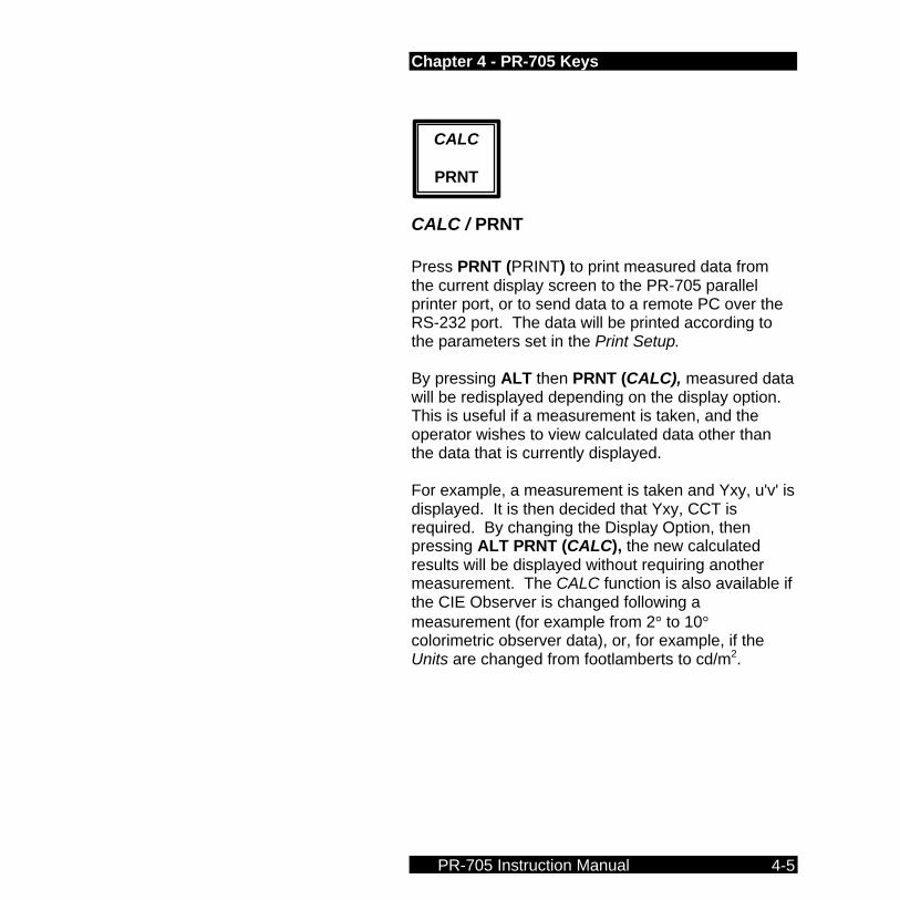
CALC / PRNT Press PRNT (PRINT) to print measured data from the current display screen to the PR-705 parallel printer port, or to send data to a remote PC over the RS-232 port. The data will be printed according to the parameters set in the Print Setup. By pressing ALT then PRNT (CALC), measured data will be redisplayed depending on the display option. This is useful if a measurement is taken, and the operator wishes to view calculated data other than the data that is currently displayed. For example, a measurement is taken and Yxy, u'v' is displayed. It is then decided that Yxy, CCT is required. By changing the Display Option, then pressing ALT PRNT (CALC), the new calculated results will be displayed without requiring another measurement. The CALC function is also available if the CIE Observer is changed following a measurement (for example from 2° to 10° colorimetric observer data), or, for example, if the Units are changed from footlamberts to cd/m2.
CALC
PRNT

Chapter 4 - PR-705 Keys
PR-705 Instruction Manual 4-6
STOP / MEAS Press the MEAS key to begin a measurement sequence. Press ALT then MEAS (STOP) to abort a measurement in progress. All data from the aborted measurement will be lost.
STOP
MEAS
Chapter 5 - PR-705 Screens
PR-705 Instruction Manual 5-1
Chapter 5 Chapter 5 -- PR-705 Screens Overview The PR-705 is controlled and data is displayed on the built-in 4 x 20 back lit LCD display. All hardware options including optical accessories (lenses, reflectance standards etc.), apertures, measurement display options, printing options, time and date and file operations are controlled from one of 8 set-up screens. NOTE: Changes to hardware setup parameters
are lost when the instrument is turned off. For more information on saving changes, see the Save, Load Setup section later in this chapter for more details.
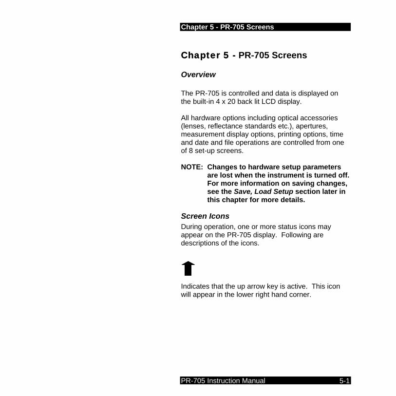
Screen Icons During operation, one or more status icons may appear on the PR-705 display. Following are descriptions of the icons.
Indicates that the up arrow key is active. This icon will appear in the lower right hand corner.

Chapter 5 - PR-705 Screens
PR-705 Instruction Manual 5-2
Indicates that the down arrow key is active. This icon will appear in the lower right hand corner of the display.
Indicates that the FRWD key is active. This icon will appear in the lower right corner of the display.
Indicates that the ENTR key is active. This icon will appear in the lower right hand corner of the display.
Indicates that the PRNT key is active. This icon will appear in the lower right hand corner of the display.
This icon, which appears in the upper right hand corner of the display, means that a measurement may be started by pressing the MEAS key.
FF
EE
PP
Chapter 5 - PR-705 Screens
PR-705 Instruction Manual 5-3
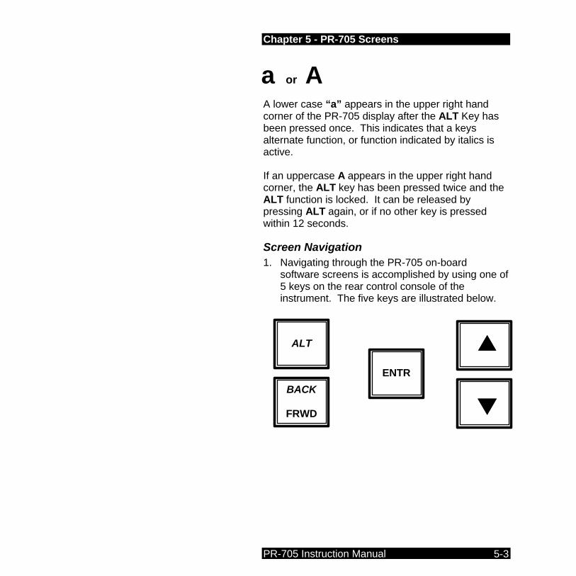
A lower case “a” appears in the upper right hand corner of the PR-705 display after the ALT Key has been pressed once. This indicates that a keys alternate function, or function indicated by italics is active. If an uppercase A appears in the upper right hand corner, the ALT key has been pressed twice and the ALT function is locked. It can be released by pressing ALT again, or if no other key is pressed within 12 seconds.
Screen Navigation 1. Navigating through the PR-705 on-board
software screens is accomplished by using one of 5 keys on the rear control console of the instrument. The five keys are illustrated below.
ALT
ss
tt
BACK
FRWD
ENTR
a or A

Chapter 5 - PR-705 Screens
PR-705 Instruction Manual 5-4
The BACK / FRWD key is used to scroll through screens. For example, press FRWD to go from Setup Screen #1 to Setup Screen #2. Press ALT then FRWD (same as BACK) to go from Setup Screen #2 to Setup Screen #1. The UP / DOWN (ss tt) arrow keys are used to select an item from within a menu by causing the > symbol to move from one choice to another. These keys are also used to scroll through options that are associated with a menu selection. Press the ENTR key to either select a menu item for change as indicated by the > symbol, or to select an option from within a menu item that has been changed. Once a menu item has been chosen by placing the > symbol next to it, press the ENTR key to make the options associated with the menu item active for change.
Sample Procedure #1 The following procedure outlines one of the more common menu selection procedures for the PR-705. The procedure involves scrolling through then selecting an option from within a menu item selection. For this example, a Display Option will be selected.
Procedure STEP 1 - Press FRWD until Setup Screen #2
appears.

Chapter 5 - PR-705 Screens
PR-705 Instruction Manual 5-5
STEP 2 - Press the ss or tt keys until the > symbol appears next to Display:.
STEP 3 - Press ENTR.
STEP 4 - The parameter field next to Display begins blinking indicating that this field may now be changed.
STEP 5 - Press the ss or tt keys to scroll through the available Display options until the item of choice appears.
STEP 6 - Press ENTR to select the item.
Sample Procedure #2 This is one of the more involved PR-705 menu operations. The following procedure can also be used to change the internal time or date of the PR-705. The Detector Exposure Time will be changed in this example.
Procedure
STEP 1 - Press FRWD until Setup Screen #3 appears.
STEP 2 - Press ss or tt until the > symbol is next to the left of Adptv (or Fixed).
STEP 3 - Press ENTR.
STEP 4 - Press ss or tt until Fixed appears.
STEP 5 - Press ENTR.

Chapter 5 - PR-705 Screens
PR-705 Instruction Manual 5-6
STEP 6 - Press ss or tt until the > is to the left of Expsre.
STEP 7 - Press ENTR.
STEP 8 - Press FRWD until the desired integer begins blinking.
STEP 9 - Press ss or tt until the desired integer appears.
STEP 10 - Press FRWD to cause the next field to begin blinking.
STEP 11 - Repeat STEPS 9 - 10 until the required value appears.
STEP 12 - Press ENTR to accept and exit.
Calculated Values
Following are descriptions for several of the values displayed following a measurement. Since one or more of the following parameters appears in every display screen, this list was compiled in the interest of brevity.
Y
The photometric intensity value with the possibilities being:
Chapter 5 - PR-705 Screens
PR-705 Instruction Manual 5-7
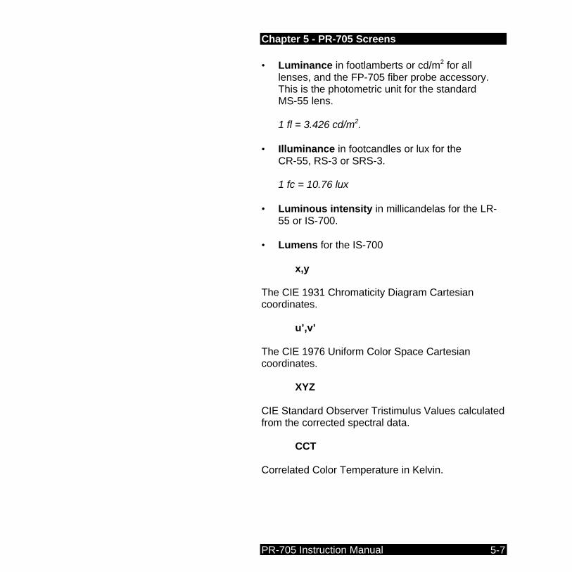
• Luminance in footlamberts or cd/m2 for all lenses, and the FP-705 fiber probe accessory. This is the photometric unit for the standard MS-55 lens. 1 fl = 3.426 cd/m2.
• Illuminance in footcandles or lux for the CR-55, RS-3 or SRS-3. 1 fc = 10.76 lux
• Luminous intensity in millicandelas for the LR-55 or IS-700.
• Lumens for the IS-700 x,y
The CIE 1931 Chromaticity Diagram Cartesian coordinates.
u’,v’
The CIE 1976 Uniform Color Space Cartesian coordinates.
XYZ
CIE Standard Observer Tristimulus Values calculated from the corrected spectral data.
CCT
Correlated Color Temperature in Kelvin.

Chapter 5 - PR-705 Screens
PR-705 Instruction Manual 5-8
Screen Descriptions
Setup Screen #1 – Accessory Selection This screen is used to select the optical accessories that will be used for the next measurement including the Primary Lens and any ancillary accessories (Add1 or Add2).
Setup Screen #1 >Lens:MS-55 Add1:None Add2:None
Lens This field provides a menu for the user to select the Primary Lens to be used for a measurement. The standard Primary Lens for the PR-705 is the MS-55 variable focus objective lens. At least one Lens must be selected to perform a measurement. Use Sample Procedure #1 to select the Lens.
NOTE: Only those Lenses and other accessories calibrated with the PR-705 will appear as choices in the Lens or Add menus.

Chapter 5 - PR-705 Screens
PR-705 Instruction Manual 5-9
Add1 or Add2 These are optical accessories that may be used in combination with the Lens. For example, Neutral Density (ND) Filters such as the ND-700-10 and Reflectance Standards such as the SRS-3. The optical characteristics for these types of accessories remain constant regardless of the type of Lens in use. Use Sample Procedure #1 to select an Add1 or Add2 optical accessory.
Setup Screen #2 – Display Options, Aperture Selection and Photometric Units Selection This section will provide instructions selecting the data type displayed following a measurement, the aperture used for the next and subsequent measurements and the photometric units (English or SI) type.
Setup Screen #2 >Display:Yxy, u'v' Aperture:2 deg. Units:fL
Display Use Sample Procedure #1 to select Display options. Display options include:
Yxy, u’v’
Sample Result Screen 2.919e+1 fL - x=.4476 y=.4074 u'=.2560 v'=.5243 2°
Y x, y
u', v' 2°° observer used

Chapter 5 - PR-705 Screens
PR-705 Instruction Manual 5-10
Yxy, CCT
Sample result screen 2.919e+1 fL - x=.4476 y=.4074 CCT=2856K +.0000 uv 2°
Yu’v’, CCT
Sample result screen: 2.919e+1 fL - u'=.2560 v'=.5243 CCT=2856K +.0000 uv 2°
XYZ, CCT
Sample result screen: X=1.098e+2 - Y=1.000e+2 CT=2856K Z=3.558e+1 +.0000 uv 2°
Radiometric
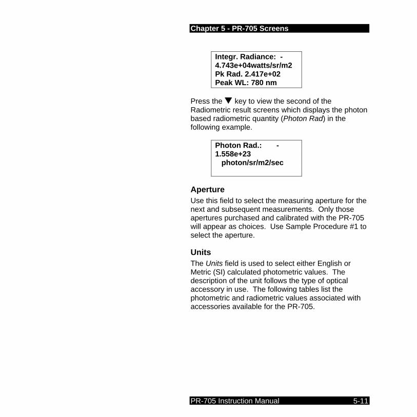
After a measurement with the Radiometric display option selected, the following screen appears displaying the integrated (total) radiometric value (Integr. Radiance in the sample result screen), the radiometric value at the peak (Pk Rad. In the sample result screen) and the wavelength in nanometers (nm) where the peak value occurs.
Sample result screen:
Correlated Color Temperature and 1960 uv deviation or distance from Planck’s blackbody radiator in CIE 1960 uv chromaticity coordinates.
Chapter 5 - PR-705 Screens
PR-705 Instruction Manual 5-11
Integr. Radiance: - 4.743e+04watts/sr/m2 Pk Rad. 2.417e+02 Peak WL: 780 nm
Press the t key to view the second of the Radiometric result screens which displays the photon based radiometric quantity (Photon Rad) in the following example.
Photon Rad.: - 1.558e+23 photon/sr/m2/sec
Aperture Use this field to select the measuring aperture for the next and subsequent measurements. Only those apertures purchased and calibrated with the PR-705 will appear as choices. Use Sample Procedure #1 to select the aperture.
Units The Units field is used to select either English or Metric (SI) calculated photometric values. The description of the unit follows the type of optical accessory in use. The following tables list the photometric and radiometric values associated with accessories available for the PR-705.

Chapter 5 - PR-705 Screens
PR-705 Instruction Manual 5-12
Photometric Units
Accessory English Metric (SI)
All lenses and the FP-55 Fiber
Probe
fL (foot-lamberts) Cd/m2
CR-55, RS-3, SRS-3
fc (foot-candles) Lux
LR-55 mcd (milli-candelas)
mcd (milli-candelas)
IS-700 mcd or lumens mcd or lumens
Radiometric Units
Accessory Radiometric Unit
All lenses and the FP-55 Fiber
Probe
w/sr/m2 (watts per steradian per square meter)
CR-55, RS-3, SRS-3 w/m2 (watts/square meter)
LR-55 w/sr (watts per steradian)
IS-700 w/sr or w (watts)
Setup Screen #3 – Detector Exposure Time, Capture Method and Cycles to Average Selection From Setup Screen #3, data capture parameters such as detector exposure time (Expsre), Adaptive Sensitivity or Fixed Exposure time, (Adptv in the following example screen), single or continuous

Chapter 5 - PR-705 Screens
PR-705 Instruction Manual 5-13
Capture and 1 - 99 Cycles to average can be selected.
Setup Screen #3 >Expsre:00300 Fixed Capture:Single Cycles:01
Expsre Select from 25 ms to 60,000 ms (1 minute) as a fixed detector exposure time, if the field to the right of Expsre is set to Fixed as shown above. If this field is set to Adptv, the PR-705 will automatically select the proper detector exposure time. Use Sample Procedure #2 to enter the exposure time.
Fixed Set this field to either Fixed or Adptv. If set to Fixed, the user sets the detector exposure time in the Exprse field. When set to Adptv, the PR-705 automatically determines the proper exposure time and disregards the value in the Expsre field. Use Sample Procedure #1 to change this field.
Capture The setting in the Capture field commands the PR-705 / 715 to either make a Single measurement, or to make Continuous measurements.
Setup Screen #3 Expsre:00300 >Adptv Capture:Single Chapter 2 Cycles:01
Chapter 5 - PR-705 Screens
PR-705 Instruction Manual 5-14
If Continuous is selected, the PR-705 continually makes measurements until ALT then MEAS (STOP) is pressed between measurements (abort sequence). Use Sample Procedure #1 to change this field.
Cycles For each measurement, the PR-705 will average the number of Cycles specified in this field. The range of possible cycles is 1 (factory default) to 99 cycles. During the measurement, the PR-705 / 715 sums the uncorrected measured data then averages these data after all cycles are completed. Photometric and colorimetric are calculated from the averaged data.
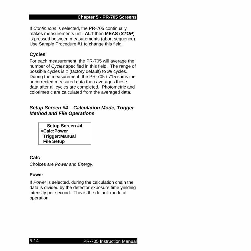
Setup Screen #4 – Calculation Mode, Trigger Method and File Operations
Setup Screen #4 >Calc:Power Trigger:Manual File Setup
Calc Choices are Power and Energy.
Power
If Power is selected, during the calculation chain the data is divided by the detector exposure time yielding intensity per second. This is the default mode of operation.
Chapter 5 - PR-705 Screens
PR-705 Instruction Manual 5-15
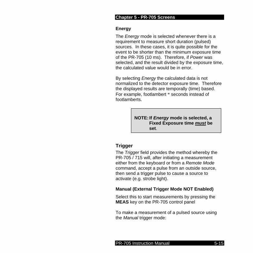
Energy
The Energy mode is selected whenever there is a requirement to measure short duration (pulsed) sources. In these cases, it is quite possible for the event to be shorter than the minimum exposure time of the PR-705 (10 ms). Therefore, if Power was selected, and the result divided by the exposure time, the calculated value would be in error.
By selecting Energy the calculated data is not normalized to the detector exposure time. Therefore the displayed results are temporally (time) based. For example, footlambert ∗ seconds instead of footlamberts.
Trigger The Trigger field provides the method whereby the PR-705 / 715 will, after initiating a measurement either from the keyboard or from a Remote Mode command, accept a pulse from an outside source, then send a trigger pulse to cause a source to activate (e.g. strobe light).
Manual (External Trigger Mode NOT Enabled)
Select this to start measurements by pressing the MEAS key on the PR-705 control panel
To make a measurement of a pulsed source using the Manual trigger mode:
NOTE: If Energy mode is selected, a
Fixed Exposure time must be set.
Chapter 5 - PR-705 Screens
PR-705 Instruction Manual 5-16
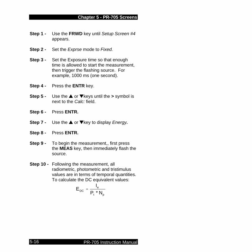
Step 1 - Use the FRWD key until Setup Screen #4
appears. Step 2 - Set the Exprse mode to Fixed. Step 3 - Set the Exposure time so that enough
time is allowed to start the measurement, then trigger the flashing source. For example, 1000 ms (one second).
Step 4 - Press the ENTR key. Step 5 - Use the ss or ttkeys until the > symbol is
next to the Calc: field. Step 6 - Press ENTR. Step 7 - Use the ss or ttkey to display Energy. Step 8 - Press ENTR. Step 9 - To begin the measurement,, first press
the MEAS key, then immediately flash the source.
Step 10 - Following the measurement, all
radiometric, photometric and tristimulus values are in terms of temporal quantities. To calculate the DC equivalent values:
pt
eDC NP
IE
*=

Chapter 5 - PR-705 Screens
PR-705 Instruction Manual 5-17
where:
EDC = Equivalent DC value
Ie = PR-705 Energy reading
Pt = Width of a single pulse
Np = Number of pulses measured in a single measurement sequence.
External
External triggering is an option to the standard PR-705 features. If your instrument was equipped with this option, please see Appendix E for further details.
File Setup The File Setup options are used to define if and how files are stored to the PR-705 on-board disk drive.
The PR-705 creates or checks for three files if a removable disk is present in the drive when the instrument is turned on. These files are useable by the PR-705 only and cannot be directly read by other programs. The files are:
• 12345678.MEA
This is a binary file that contains measured data and is appended whenever the PR-705 is instructed to store a measurement.
NOTE: The numbers (for example: 12345678) in the following file names represent all or part of the serial number of the PR-705.
Chapter 5 - PR-705 Screens
PR-705 Instruction Manual 5-18
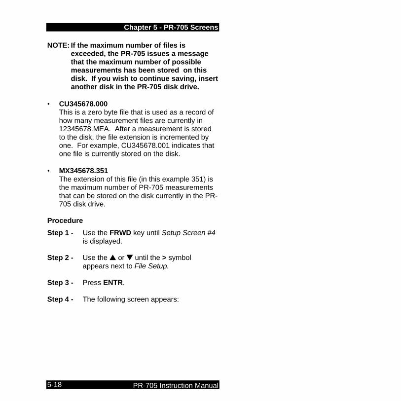
NOTE: If the maximum number of files is exceeded, the PR-705 issues a message that the maximum number of possible measurements has been stored on this disk. If you wish to continue saving, insert another disk in the PR-705 disk drive.
• CU345678.000
This is a zero byte file that is used as a record of how many measurement files are currently in 12345678.MEA. After a measurement is stored to the disk, the file extension is incremented by one. For example, CU345678.001 indicates that one file is currently stored on the disk.
• MX345678.351
The extension of this file (in this example 351) is the maximum number of PR-705 measurements that can be stored on the disk currently in the PR-705 disk drive.
Procedure
Step 1 - Use the FRWD key until Setup Screen #4 is displayed.
Step 2 - Use the ss or tt until the > symbol
appears next to File Setup. Step 3 - Press ENTR. Step 4 - The following screen appears:

Chapter 5 - PR-705 Screens
PR-705 Instruction Manual 5-19
Store
This field is used to instruct the PR-705 to either disallow storing measurement data, allow manual (keyboard initiated) storage or unattended (automatic) file storage.
While the PR-705 is storing the measurement data, the following screen will briefly appear
In the preceding example, the number on the bottom line of the display, 0106981601 is the Volume Label of the disk in the PR-705 disk drive.
If there is no disk in the drive when the Store command is given, the following screen appears:
File Store/Recall >Store:Off Recall:File # N.A Vol:0106981444
Writing Meas #010 on disk 0106981601
ERROR Storage Disk is: Not AVAILABLE
Retry: Cancel:

Chapter 5 - PR-705 Screens
PR-705 Instruction Manual 5-20
Insert an IBM formatted disk in the drive and press the s key to store the data, or press the t key to cancel the operation. Following a successful measurement store function, the system returns to the display screen. At this point, the current display screen is updated with the measurement number as shown in the following example:
2.919e+1 fL - u'=.2560 v'=.5243 CCT=2856K +.0000 uv I.D #: 002 2°
In the preceding example, the measurement data is saved as file (ID#) 2.
Use Sample Procedure #1 to select the desired option in the Store Field.
• Off No data storage is allowed.
• Manual Data is saved after a measurement by pressing the ENTR key. Alternately, data may be saved after a CALC (ALT PRNT key sequence) operation by pressing the ENTR key.
• Auto The PR-705 will automatically store data following a measurement.

Chapter 5 - PR-705 Screens
PR-705 Instruction Manual 5-21
• If both Store and Print are simultaneously set to Auto, the PR-705 will store the measured data before printing.
Recall
The Recall function is used to view and or print previously stored measurement data. Recall Procedure
STEP 1 - Press the s or t key to place the > symbol next to the file number (see following example). Press the ENTR key.
STEP 2 - The least significant digit of the File #
begins blinking and can now be edited.
STEP 3 - Press the s or t key to change the digit number (press and hold either key to scroll).
STEP 4 - Press FRWD to cause the next digit to begin blinking.
STEP 5 - Press the s or t keys to change the digit.
STEP 6 - Repeat Steps 5 – 6 until the desired File # appears.
File Store/Recall Store:Manual Recall:File # >001 Vol:0106981444
Chapter 5 - PR-705 Screens
PR-705 Instruction Manual 5-22
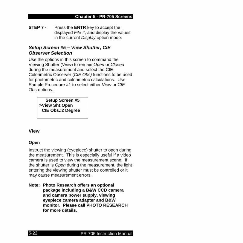
STEP 7 - Press the ENTR key to accept the displayed File #, and display the values in the current Display option mode.
Setup Screen #5 – View Shutter, CIE Observer Selection Use the options in this screen to command the Viewing Shutter (View) to remain Open or Closed during the measurement and select the CIE Colorimetric Observer (CIE Obs) functions to be used for photometric and colorimetric calculations. Use Sample Procedure #1 to select either View or CIE Obs options.
Setup Screen #5 >View Sht:Open CIE Obs.:2 Degree
View
Open
Instruct the viewing (eyepiece) shutter to open during the measurement. This is especially useful if a video camera is used to view the measurement scene. If the shutter is Open during the measurement, the light entering the viewing shutter must be controlled or it may cause measurement errors. Note: Photo Research offers an optional
package including a B&W CCD camera and camera power supply, viewing eyepiece camera adapter and B&W monitor. Please call PHOTO RESEARCH for more details.

Chapter 5 - PR-705 Screens
PR-705 Instruction Manual 5-23
If in doubt whether to leave this shutter open or closed during a measurement, make sure it is set to the Closed position.
Closed (Power on default)
The viewing shutter remains closed during the measurement, then opens when the measurement is completed.
CIE Obs
2 Degree (Power on default)
The CIE 1931 Standard Observer Functions for a 2° visual field are used following the measurement to calculate photometric brightness, CIE 1931 xy, CIE 1976 u’v’ chromaticity coordinates and correlated color temperature.
Chapter 5 - PR-705 Screens
PR-705 Instruction Manual 5-24
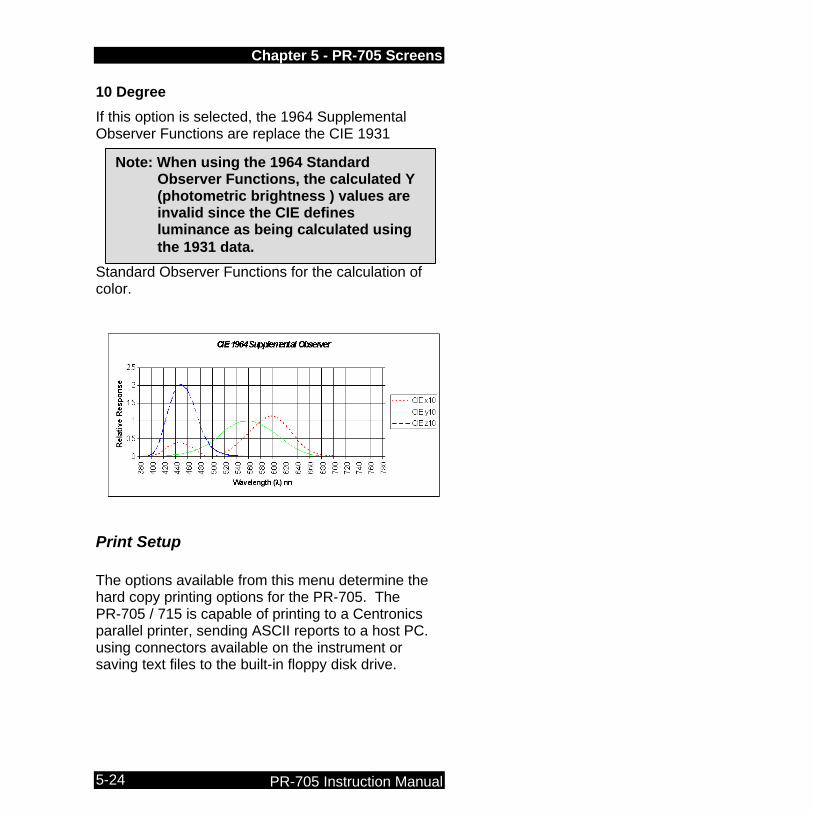
10 Degree
If this option is selected, the 1964 Supplemental Observer Functions are replace the CIE 1931
Standard Observer Functions for the calculation of color.
Print Setup The options available from this menu determine the hard copy printing options for the PR-705. The PR-705 / 715 is capable of printing to a Centronics parallel printer, sending ASCII reports to a host PC. using connectors available on the instrument or saving text files to the built-in floppy disk drive.
Note: When using the 1964 Standard Observer Functions, the calculated Y (photometric brightness ) values are invalid since the CIE defines luminance as being calculated using the 1931 data.

Chapter 5 - PR-705 Screens
PR-705 Instruction Manual 5-25
Since the PR-705 prints only American Standard Code for Information Interchange (ASCII) formatted text data with no graphics, it will work with virtually any printer: laser jet, ink jet or dot matrix.
Mode
The mode selection is used to choose between no printing (Off), Manual printing or Auto printing. Use Sample Procedure #1 to select the print Mode.
Off
Select Off to disable all printing functions.
Manual
By choosing Manual, the data is sent to the selected port after a measurement by pressing the PRNT key.
Manual store is available following a measurement, or whenever the Calc (ALT PRNT key sequence) is executed.
Print Setup >Mode: Manual Format: View Screen Port: Parallel
Note: If the Mode field is set to Off, no other menu choices (Format or Port) can be accessed. The Mode must be set to either Manual or Auto.

Chapter 5 - PR-705 Screens
PR-705 Instruction Manual 5-26
Auto
Set the Mode field to Auto to instruct the PR-705 to automatically print to the selected Port in the selected Format after each measurement. The Auto store function is only available following a measurement.
Format The Format field determines what type of report is to be printed. The choices are Disp. Scrn, Full Report and Spectral. Use Sample Procedure #1 to make changes in the Format field.
Disp. Scrn
Prints a copy of what is currently being displayed on the PR-705 screen. Using this format, up to 12 screens can be printed on an 8.5" x 11" page. To see hard copy results before the twelfth display is printed, use your printers form feed function.
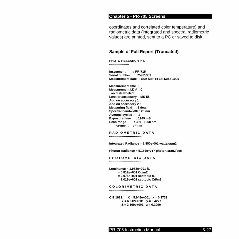
Full Report
This two page print out is a full, verbose report of all measured data including instrument setup information, measurement time and date, measurement ID# and disk label if data from a recalled measurement is being printed. Additionally, photometric (luminance, illuminance etc., scotopic luminance), colorimetric (CIE chromaticity
Note: If Auto Print and Auto Store are enabled simultaneously, the PR-705 will store data before printing.
Chapter 5 - PR-705 Screens
PR-705 Instruction Manual 5-27
coordinates and correlated color temperature) and radiometric data (integrated and spectral radiometric values) are printed, sent to a PC or saved to disk. Sample of Full Report (Truncated) PHOTO RESEARCH Inc. ------------------- Instrument : PR-715 Serial number : 75981301 Measurement date : Sun Mar 14 18:43:54 1999 Measurement title : Measurement I.D # : 0 on disk labeled : Lens or accessory : MS-55 Add on accessory 1 : Add on accessory 2 : Measuring field : 1 deg. Spectral bandwidth : 20 nm Average cycles : 1 Exposure time : 1249 mS Scan range : 380 - 1068 nm increment : 4 nm R A D I O M E T R I C D A T A ------------------------------- Integrated Radiance = 1.850e-001 watts/sr/m2 Photon Radiance = 5.186e+017 photon/sr/m2/sec P H O T O M E T R I C D A T A ------------------------------- Luminance = 1.988e+001 fL = 6.812e+001 Cd/m2 = 2.975e+001 scotopic fL = 1.019e+002 scotopic Cd/m2 C O L O R I M E T R I C D A T A --------------------------------- CIE 1931: X = 5.945e+001 x = 0.3733 Y = 6.812e+001 y = 0.4277 Z = 3.169e+001 z = 0.1990
Chapter 5 - PR-705 Screens
PR-705 Instruction Manual 5-28
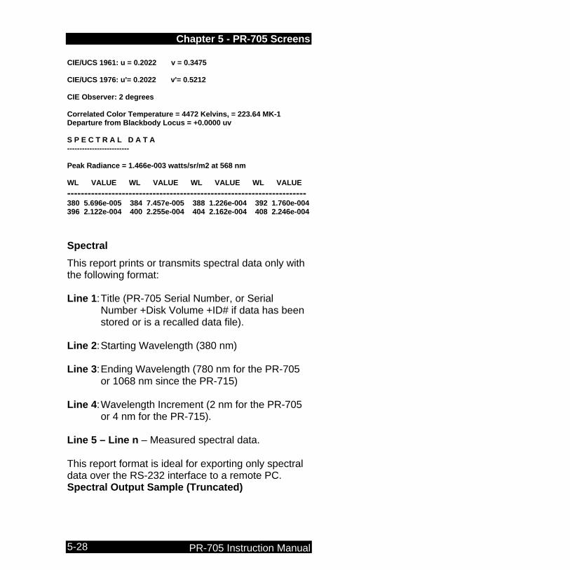
CIE/UCS 1961: u = 0.2022 v = 0.3475 CIE/UCS 1976: u'= 0.2022 v'= 0.5212 CIE Observer: 2 degrees Correlated Color Temperature = 4472 Kelvins, = 223.64 MK-1 Departure from Blackbody Locus = +0.0000 uv S P E C T R A L D A T A ------------------------- Peak Radiance = 1.466e-003 watts/sr/m2 at 568 nm WL VALUE WL VALUE WL VALUE WL VALUE ---------------------------------------------------------------------- 380 5.696e-005 384 7.457e-005 388 1.226e-004 392 1.760e-004 396 2.122e-004 400 2.255e-004 404 2.162e-004 408 2.246e-004 Spectral
This report prints or transmits spectral data only with the following format: Line 1: Title (PR-705 Serial Number, or Serial
Number +Disk Volume +ID# if data has been stored or is a recalled data file).
Line 2: Starting Wavelength (380 nm) Line 3: Ending Wavelength (780 nm for the PR-705
or 1068 nm since the PR-715) Line 4: Wavelength Increment (2 nm for the PR-705
or 4 nm for the PR-715). Line 5 – Line n – Measured spectral data. This report format is ideal for exporting only spectral data over the RS-232 interface to a remote PC. Spectral Output Sample (Truncated)

Chapter 5 - PR-705 Screens
PR-705 Instruction Manual 5-29
75981301 380 1068 4 5.092e-005 7.063e-005 1.272e-004 1.800e-004 2.126e-004 2.258e-004 2.151e-004 2.246e-004 2.613e-004 3.342e-004 5.611e-004 Use Sample Procedure #1 to make Printer Setup selections.
Port The Port field provides selection for sending data to the on-board Parallel printer port or RS-232 Serial interface. Parallel
Select Parallel if a standard parallel printer is connected to the PR-705 25-pin sub-d female connector.
Serial
Serial should be selected if the user wishes to "print" (send) data to a remote PC or RS-232 printer. The PR-705 can be connected to a PC via the 9 pin sub-d female connector and supplied RS-232 cable (see the Connectors section in Chapter 2 for RS-232 pin-out information).
Chapter 5 - PR-705 Screens
PR-705 Instruction Manual 5-30
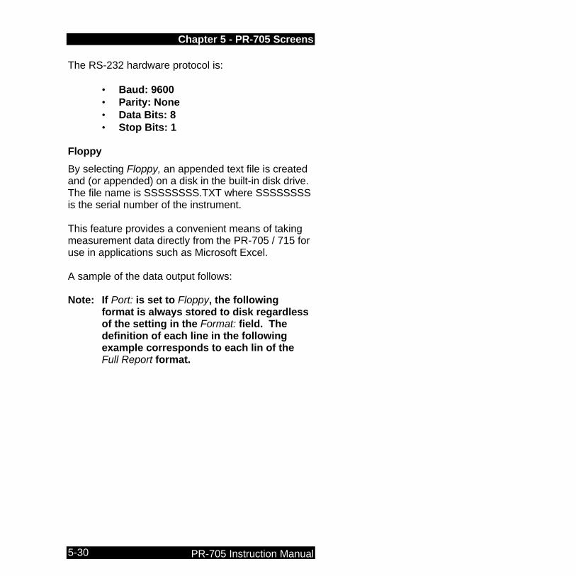
The RS-232 hardware protocol is: • Baud: 9600 • Parity: None • Data Bits: 8 • Stop Bits: 1
Floppy
By selecting Floppy, an appended text file is created and (or appended) on a disk in the built-in disk drive. The file name is SSSSSSSS.TXT where SSSSSSSS is the serial number of the instrument. This feature provides a convenient means of taking measurement data directly from the PR-705 / 715 for use in applications such as Microsoft Excel. A sample of the data output follows: Note: If Port: is set to Floppy, the following
format is always stored to disk regardless of the setting in the Format: field. The definition of each line in the following example corresponds to each lin of the Full Report format.
Chapter 5 - PR-705 Screens
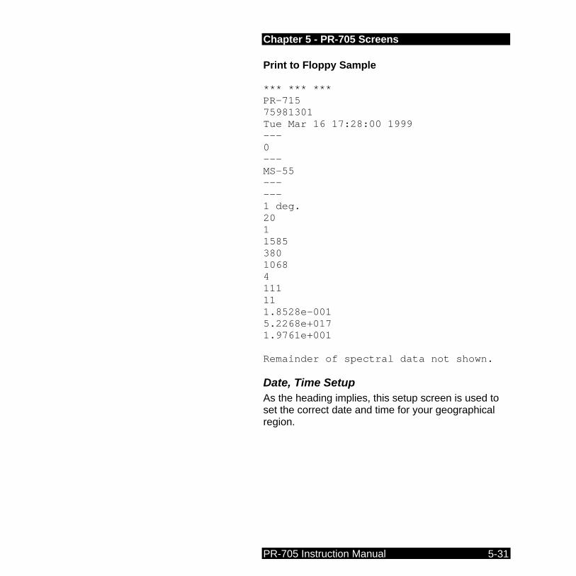
PR-705 Instruction Manual 5-31
Print to Floppy Sample *** *** *** PR-715 75981301 Tue Mar 16 17:28:00 1999 --- 0 --- MS-55 --- --- 1 deg. 20 1 1585 380 1068 4 111 11 1.8528e-001 5.2268e+017 1.9761e+001 Remainder of spectral data not shown.
Date, Time Setup As the heading implies, this setup screen is used to set the correct date and time for your geographical region.
Chapter 5 - PR-705 Screens
PR-705 Instruction Manual 5-32
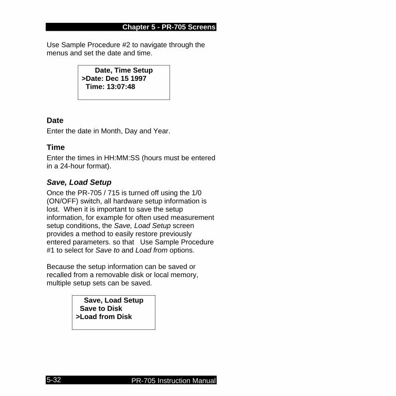
Use Sample Procedure #2 to navigate through the menus and set the date and time.
Date, Time Setup >Date: Dec 15 1997 Time: 13:07:48
Date Enter the date in Month, Day and Year.
Time Enter the times in HH:MM:SS (hours must be entered in a 24-hour format).
Save, Load Setup Once the PR-705 / 715 is turned off using the 1/0 (ON/OFF) switch, all hardware setup information is lost. When it is important to save the setup information, for example for often used measurement setup conditions, the Save, Load Setup screen provides a method to easily restore previously entered parameters. so that Use Sample Procedure #1 to select for Save to and Load from options. Because the setup information can be saved or recalled from a removable disk or local memory, multiple setup sets can be saved.
Save, Load Setup Save to Disk >Load from Disk

Chapter 5 - PR-705 Screens
PR-705 Instruction Manual 5-33
Save to Memory Saves the current hardware setup information to memory on-board the PR-705. Only one set of instrument setup parameters can be saved in memory.
Save to Disk Saves the current hardware setup information to a disk in the built-in floppy drive. Only one set of instrument setup parameters can be saved per disk.
Load from to Memory Loads the saved setup parameters from the PR-705 on-board memory.
Load from Disk Recalls a file containing setup parameters from a floppy disk in the built-in disk drive. Procedure STEP 1 - Use the FRWD key until the Save, Load
Setup screen appears. STEP 2 - Use the s or t keys to position the >
symbol next to either the Load or Save fields.
STEP 3 - Press the ENTR key. STEP 4 - Use the s or t keys to select Memory
or Disk. STEP 5 - Press the ENTR key again to execute
the selection.
Chapter 5 - PR-705 Screens
PR-705 Instruction Manual 5-34
or Press ENTR twice to execute the currently displayed selection.
Chapter 6 - Maintenance
PR-705 Instruction Manual 6-1
Chapter 6 Chapter 6 -- Maintenance The PR-705/715 SpectraScan has been designed to give long, trouble-free service requiring a minimum in routine maintenance. The PR-705 does not require any routine maintenance with the exception of cleaning optical surfaces such as those found on objective lenses. To clean lenses:
Cleaning Lenses Step 1 - Remove the objective lens from the
instrument. All objective lenses can be removed from the front of the PR-705 by grasping at the base of the lens (part of the lens closest to the instrument)
Step 2 - Using a lint free cloth such as commercially available lens tissue and lens cleaning fluid or anhydrous alcohol, gently clean the surface using a circular motion. Do not use excessive pressure.
Note: Attempting unauthorized repairs beyond the instructions in this manual voids the instrument warranty.

Chapter 6 - Maintenance
PR-705 Instruction Manual 6-2
Re-calibration The PR-705 / 715 factory calibration is certified for six months. Although the instrument may provide accurate results beyond the six-month period, it is recommended that re-calibration be performed every six months. Contact PHOTO RESEARCH regarding re-calibration services for the PR-705 / 715. User Calibration Contact PHOTO RESEARCH for information on user calibration software and calibration standards (wavelength and intensity).
Factory Repair
In-Warranty Repair PHOTO RESEARCH warrants trouble free operation for one year from date the instrument leaves the factory. If the instrument malfunctions during the one-year period, it will be repaired at no charge to the customer. The one-year is voided if the PR-705/715 has bee tampered with, is subject to physical damage intentional or unintentional or is misused. Contact the PHOTO RESEARCH Service Department at 818-341-5151 for a Returned Material Authorization number before sending the instrument in for any reason. When returning the instrument, make sure to include all optical accessories. Accessories that are not returned cannot be calibrated.
Chapter 6 - Maintenance
PR-705 Instruction Manual 6-3
Returning an Instrument When returning an instrument to PHOTO RESEARCH for any reason, contact PHOTO RESEARCH for an Returned Material Authorization RMA number. Instruments returned without an RMA number will not be processed. Pack the PR-705 / 715, preferably in the original crates or carrying cases. Shipping Charges Ship the instrument pre-paid. Instruments shipped COD will be returned unopened.


Glossary of Terms
PR-705 Operating Manual A
Glossary of Terms
CIE The Commission Internationale de l’Eclairage (CIE) is the international commission on illumination. They are dedicated to creating and maintaining international standards in the field of lighting.
CIE Chromaticity Coordinates The proportions of CIE tristimulus values required to define a color in a Cartesian system such as the CIE 1931 Chromaticity Diagram or the CIE 1976 Uniform Color Space. They are designated as x, y, z or u',v' and are the ratios of each of the tristimulus values X, Y and Z in relation to the sum of the three.
CIELAB Internationally accepted color space model used as a standard to define color within many industries. This 3-dimensional model designates L for the lightness axis, A for the red-green axis and B for the yellow-blue axis.

Glossary of Terms
B PR-705 Instruction Manual
Correlated Color Temperature (CCT) Term used to describe the color of white light sources. Specifically, it is the temperature of a Planckian (black body) radiator, which produces the chromaticity coordinates most similar to that of the light source. It is customarily expressed in degrees Kelvin (K).
Filter Photometer A photometer which incorporates a filter with a response that matches the detector to the 1931 CIE luminous efficiency (V(λ)) function. Photometric quantities are obtained directly by measuring the light after it passes through the photopic filter.
Hue The attribute of color by which a color is perceived to be red, green, blue, yellow etc. Achromatic colors like black, white and gray do not exhibit hue.

Glossary of Terms
PR-705 Operating Manual C
Illuminance Luminous Flux incident on a surface per unit area. The SI unit of illuminance is the Lux (lumens/m2). The English unit of illuminance is the Foot-candle (lumens/ft2).
1 Lux = .0929 Foot-candles
1 Foot-candle = 10.76 Lux.
Lambertian surface A perfectly diffusing surface exhibiting the property that the light intensity emitted from any small surface component in a given direction is proportional to the cosine of the angle from the normal to the surface.
Luminance Luminous Flux emitted from a surface per unit solid angle per unit area in a given direction. The SI unit is the candela per square meter (cd/m2) and the English unit is the footlambert (1/π cd/ft2).
1 cd/m2 = 0.2919 footlambert
1 footlambert = 3.426 cd/m2.

Glossary of Terms
D PR-705 Instruction Manual
Luminous Efficiency Function The spectral response of the daylight (2° foveal) vision of the average human observer defined in 1924 by the CIE. Also called the photopic response function. The luminous efficiency function for the dark-adapted (7.5° extra foveal) eye is also known as the scotopic function.
Luminous Flux Radiant Flux weighed by the 1931 CIE photopic V(λ) function. The unit of luminous flux is the Lumen. The luminous flux per steradian from a source whose luminous intensity is one candela is one lumen.
Luminous Intensity (Candlepower) The luminous flux per unit solid angle emitted or reflected from a point source. The unit of luminous intensity is the candela.
Metamerism Phenomenon by which spectrally dissimilar radiation produces the same color sensation for an observer. A pair of metameric colors may match under one or more sets of conditions, but will appear to change in hue under spectrally different ambient lighting conditions.
Glossary of Terms
PR-705 Operating Manual E
Photometer An instrument used to measure photometric quantities like luminance, illuminance, luminous flux and luminous intensity. It can either be a filter photometer or a spectroradiometer.
Photometry The science of measuring visible light based upon the response of an average human observer.
Saturation The attribute of color perception that expresses the degree of departure from gray of the same lightness - in other words, how monochromatic or pure a color is. A completely saturated color is monochromatic (radiates at a single wavelength).
Spectroradiometer An instrument for measuring the spectral energy radiated by a source. The spectral data can be used to calculate photometric and colorimetric parameters.

Glossary of Terms
F PR-705 Instruction Manual
Standard Illuminant A series of illuminant spectral power distribution curves recommended by the CIE as standard light sources for light measurement. Examples are Illuminants A, B, C, D55, D65 etc.
Standard Observer Functions Spectral response curves that, when integrated with the spectral power distribution of the sample under test, generate the CIE tristimulus values. These curves approximate the red, green and blue responsivity of human color (2° foveal) vision.
Steradian The steradian is the unit of solid angle defined as the solid angle subtended at the center of a sphere by an area on its surface equal to the square of the radius. A sphere has 4π steradians
Supplemental Observer Functions Published in 1964, these spectral response curves, similar to the standard observer functions, are based on a 10° observation cone instead or a 2° cone. The 10° cone includes contributions from both human rods and cones.

Glossary of Terms
PR-705 Operating Manual G
Tristimulus Values The values of the three stimuli required for matching a color. The CIE tristimulus values are designated as X, Y and Z and can be used as a method of color definition.
Visible Light Electromagnetic radiation in the spectral range from 360 - 830 nm that is visible to the human observer