practical information on gears
TRANSCRIPT

Practical
Information on
Gears
This chapter provides fundamental theoretical and practical information about gearing. It also introduces various gear-related
standards as an aid for the designer who is going to use gears for his planning.

Gear Tooth Modifications...............................................................Gear Trains……………………………..............................................2.1 Planetary Gear System…………………………….....................2.2 Hypocycloid Mechanism……………….....................................2.3 Constrained Gear System……………………............................Tooth Thickness……………………………………...........................3.1 Chordal Tooth Thickness Measurement……………………………….3.2 Span Measurement ………………………………………................3.3 Measurement Over Rollers………………………….........................Backlash…………………………......................................................4.1 Backlash Relationships……………….......................................4.2 Tooth Thickness and Basklash……………………....................4.3 Gear Train and Backlash………………….................................4.4 Methods of Controlling Backlash………...................................Gear Accuracy……………………………………..............................5.1 Accuracy of Spur and Helical Gears………..............................5.2 Accuracy of Bevel Gears…………………………......................5.3 Running (Dynamic) Gear Testing……………………................Features of Tooth Contact……………………………….......……....6.1 Tooth Contact of a Bevel Gear…...………………….................6.2 Tooth Contact of a Worm Gear Pair…...…………….................Lubrication of Gears…………………………………........................7.1 Methods of Lubrication……………………………......................7.2 Gear Lubricants…………………………….................................Gear Forces………………………………..........................................8.1 Forces in a Spur Gears Mesh…………………..........................8.2 Forces in a Helical Gear Mesh……………...............................8.3 Forces in a Straight Bevel Gear Mesh………...........................8.4 Forces in a Spiral Bevel Gear Mesh……..................................8.5 Forces in a Worm Gear Pair Mesh………….............................8.6 Forces in a Screw Gear Mesh……………….............................Contact Ratio……………………………….......................................9.1 Transverse Contact Ratio, εα …………………………..............9.2 Overlap Ratio, εβ …………………….........................................Gear Noise…………………………...................................................A Method for Determining the Specifications of a Spur Gear...A Method for Determining the Specifications of a Helical Gear…...
5
21
3
4
6
7
8
9
101112
1446677
121322222525262828303132323335353739394040414345464648495050
2
Table of Contents

Practical Information on Gears
Intentional deviations from the involute tooth profile are used to avoid excessive tooth load deflection interference and thereby enhances load capacity. Also, the elimination of tip interference reduces meshing noise. Other modifications can accommodate assembly misalignment and thus preserve load capacity.
(1) Tooth Tip Relief
There are two types of tooth relief. One modifies the addendum, and the other the dedendum. See Figure 1.1. Tip relief is much more popular than root modification.Care should be taken, however, not to modify excessively since that will cause bad effect in meshing.
(2) Crowning and End Relief
Crowning and end relief are tooth surface modifications in the axial direction. Crowning is the removal of a slight amount of tooth from the center on out to reach edge, making the tooth surface slightly convex. This method allows the gear to maintain contact in the central region of the tooth and permits avoidance of edge contact with consequent lower load capacity. Crowning also allows a greater tolerance in the misalignment of gears in their assembly, maintaining central contact. The crowning should not be larger than necessary as otherwise it would reduce dimentions of tooth contact, thus weakening durable strength.End relief is the chamfering of both ends of tooth surface. See Figure 1.2.
3
(3) Topping And Semitopping
In topping, often referred to as top hobbing, the top or tip diameter of the gear is cut simultaneously with the generation of the teeth. See page 387 "The Generating of a Spur Gear". Also, refer to Figure 3.5, 3.6 and 3.7 in that section. An advantage is that there will be no burrs on the tooth top. Also, the tip diameter is highly concentric with the pitch circle. Semitopping is the chamfering of the tooth's top corner, which is accomplished simultaneously with tooth generation. Figure 1.3 shows a semitopping cutter and the resultant generated semitopped gear. Such a tooth tends to prevent corner damage. Also, it has no burr. The magnitude of semitopping should not go beyond a proper limit as otherwise it would significantly shorten the addendum and contact ratio.
Figure 1.4 specifies a recommended magnitude of semitopping They are independent modifications but, if desired, can be applied simultaneously.
1 GEAR TOOTH MODIFICATIONS
Fig. 1.1 Tip relief
Fig. 1.2 Crowning and end relief
Crowning End relief
Fig.1.3 Semitopping cutter and the gear profile generated
Teeth form of semitopping cutter Semitopped teeth form
Fig.1.4 Recommended magnitude of semitopping
90° -α2
0.1m
Practical Information on Gears
(1) Relationship Among the Gears in a Planetary Gear SystemIn order to determine the relationship among the numbers of teeth of the sun gear A (za), the planet gears B (zb) and the internal gear C (zc) and the number of planet gears (N) in the system, the parameters must satisfy the following three conditions:
Condition No.1: zc = za + 2 zb (2.1)
This is the condition necessary for the center distances of the gears to match. Since the equation is true only for the standard gear system, it is possible to vary the numbers of teeth by using profile shifted gear designs.
To use profile shifted gears, it is necessary to match the center distance between the sun A and planet B gears, a1, and the center distance between the planet B and internal C gears, a2. a1 = a2 (2.2)
Condition No.2: = Integer (2.3)
This is the condition necessary for placing planet gears evenly spaced around the sun gear. If an uneven placement of planet gears is desired, then Equation (2.4) must be satisfied.
= Integer (2.4)
Where θ : half the angle between adjacent planet gears (° )
4
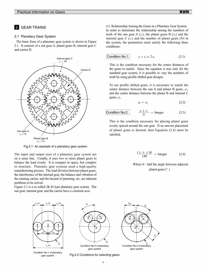
2.1 Planetary Gear System
The basic form of a planetary gear system is shown in Figure 2.1. It consists of a sun gear A, planet gears B, internal gear C and carrier D.
The input and output axes of a planetary gear system are on a same line. Usually, it uses two or more planet gears to balance the load evenly. It is compact in space, but complex in structure. Planetary gear systems need a high-quality manufacturing process. The load division between planet gears, the interference of the internal gear, the balance and vibration of the rotating carrier, and the hazard of jamming, etc. are inherent problems to be solved.Figure 2.1 is a so called 2K-H type planetary gear system. The sun gear, internal gear, and the carrier have a common axis.
2 GEAR TRAINS
Nza + zc
180( za + zc )θ
Fig.2.1 An example of a planetary gear system
Sun gear A
Carrier D
Internal gear C
Planet gear B
za =16
zb = 16
zc = 48
Fig.2.2 Conditions for selecting gearsCondition No.1 of planetary
gear system
Condition No.2 of planetary gear system
Condition No.3 of planetary gear system
CC
C
B BA
B B
A
B B
A
zb m za m zb m
zc m
a1 a2
θ dabθ
a 1
Practical Information on Gears
No.
5
Condition No.3 zb +2 < (za +zb) sin (2.5)
Satisfying this condition insures that adjacent planet gears can operate without interfering with each other. This is the condition that must be met for standard gear design with equal placement of planet gears. For other conditions, the system must satisfy the relationship: dab< 2a1 sin θ (2.6)Where:
dab : tip diameter of the planet gears a1 : center distance between the sun and
planet gearsBesides the above three basic conditions, there can be an interference problem between the internal gear C and the planet gears B. See Section 4.2 Internal Gears (Page 394).
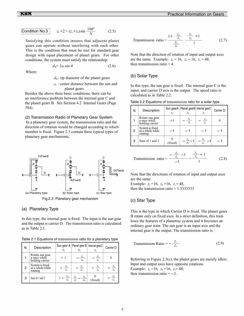
(2) Transmission Radio of Planetary Gear System In a planetary gear system, the transmission ratio and the direction of rotation would be changed according to which member is fixed. Figure 2.3 contain three typical types of planetary gear mechanisms,
Transmission ratio = = (2.7)
Note that the direction of rotation of input and output axes are the same. Example: za = 16, zb = 16, zc = 48, then transmission ratio = 4.
(b) Solar Type
In this type, the sun gear is fixed. The internal gear C is the input, and carrier D axis is the output. The speed ratio is calculated as in Table 2.2.
Transmission ratio = = (2.8)
Note that the directions of rotation of input and output axes are the same.Example: za =16, zb =16, zc = 48,then the transmission ratio = 1.3333333
(c) Star Type
This is the type in which Carrier D is fixed. The planet gears B rotate only on fixed axes. In a strict definition, this train loses the features of a planetray system and it becomes an ordinary gear train. The sun gear is an input axis and the internal gear is the output. The transmission ratio is :
Transmission Ratio = - (2.9)
Referring to Figure 2.3(c), the planet gears are merely idlers. Input and output axes have opposite rotations.Example: za =16, zb =16, zc= 48; then transmission ratio = -3 .
Table 2.1 Equations of transmission ratio for a planetary type
1
2
3
Description
Rotate sun gear a once while holding carrierSystem is fixed as a whole while rotating
Sum of 1 and 2
Sun gear Aza
+ 1
+
1 +
Planet gear Bzb
-
+
-
-
+
0(fixed)
Carrier D
0
+
+
No.
Table 2.2 Equations of transmission ratio for a solar type
1
2
3
Description
Rotate sun gear a once while holding carrierSystem is fixed as a whole while rotating
Sum of 1 and 2
Sun gearAza
+1
-1
0(fixed)
Planet gearBzb
-
- 1
- -1
Internal gearCzc
-
- 1
- -1
Carrier D
0
- 1
- 1
N 180°
Fig.2.3 Planetary gear mechanism
C(Fixed)
D
B
A
B B
DD(Fixed)
C C
A(Fixed) A
(a) Planetary type (b) Solar type (c) Star type
zc
za
zc
zazb
zazc
za
zc
za
zc
zazc
zazc
za
zc
zazb
za
zb
zazc
za
zb
za
zc
za
zc
za
1+
zc
za
zc
za
za
zc +1
1
zc
za
-1
- -1 zc
za + 1
1
(a) Planetary Type
In this type, the internal gear is fixed. The input is the sun gear and the output is carrier D. The transmission ratio is calculated as in Table 2.1.
Internal gearCzc
Practical Information on Gears
6
2.3 Constrained Gear System
A planetary gear system which has four gears is an example of a constrained gear system. It is a closed loop system in which the power is transmitted from the driving gear through other gears and eventually to the driven gear. A closed loop gear system will not work if the gears do not meet specific conditions.
Let z1, z2 and z3 be the numbers of gear teeth, as in Figure 2.5. Meshing cannot function if the length of the heavy line (belt) does not divide evenly by pitch. Equation (2.11) defines this condition.
+ + = integer (2.11)
F igure 2 .6 shows a constrained gear system in which a rack is meshed. The heavy line in Figure 2.6 corresponds to the belt in Figure 2.5. If the length of the belt cannot be evenly divided by pitch then the system does not work. It is described by Equation (2.12).
+ + = integer (2.12)
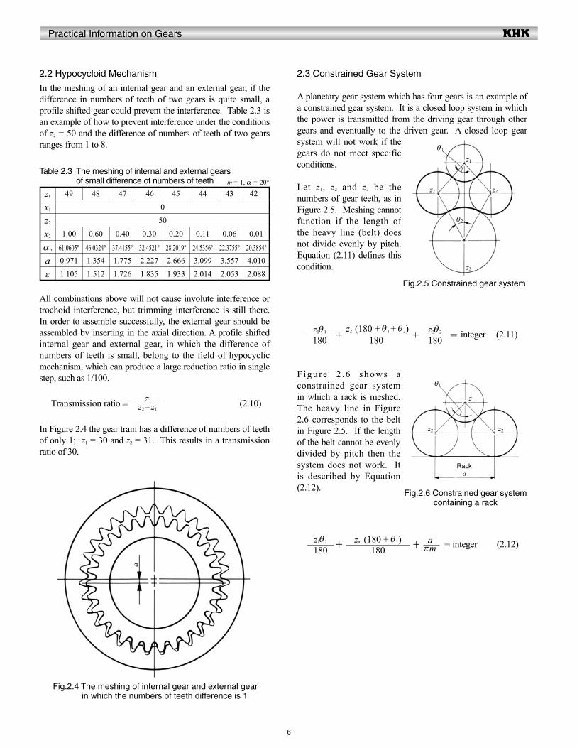
2.2 Hypocycloid Mechanism
In the meshing of an internal gear and an external gear, if the difference in numbers of teeth of two gears is quite small, a profile shifted gear could prevent the interference. Table 2.3 is an example of how to prevent interference under the conditions of z2 = 50 and the difference of numbers of teeth of two gears ranges from 1 to 8.
Table 2.3 The meshing of internal and external gears of small difference of numbers of teeth
All combinations above will not cause involute interference or trochoid interference, but trimming interference is still there. In order to assemble successfully, the external gear should be assembled by inserting in the axial direction. A profile shifted internal gear and external gear, in which the difference of numbers of teeth is small, belong to the field of hypocyclic mechanism, which can produce a large reduction ratio in single step, such as 1/100.
Transmission ratio = (2.10)
In Figure 2.4 the gear train has a difference of numbers of teeth of only 1; z1 = 30 and z2 = 31. This results in a transmission ratio of 30.
46m = 1, α = 20°
z1
x1
z2
x2
αb
aε
49
0
50
1.00 0.60 0.40 0.30 0.20 0.11 0.06 0.01
61.0605° 46.0324° 37.4155° 32.4521° 28.2019° 24.5356° 22.3755° 20.3854°0.971 1.354 1.775 2.227 2.666 3.099 3.557 4.010
1.105 1.512 1.726 1.835 1.933 2.014 2.053 2.088
48 47 45 44 43 42
z1z2 - z1
Fig.2.4 The meshing of internal gear and external gear in which the numbers of teeth difference is 1
a
Fig.2.5 Constrained gear system
θ1
θ2
z2 z2
z1
z3
θ1
z2 z2
z1
Fig.2.6 Constrained gear systemcontaining a rack
Racka
180z3θ 2
180z2 (180 + θ 1 + θ 2)
180z1θ 1
180z1θ 1
180za (180 + θ 1)
πma
Practical Information on Gears
Exmple
7
There are direct and indirect methods for measuring tooth thickness. In general, there are three methods: • Chordal tooth thickness measurement • Span measurement • Over pin or ball measurement
3.1 Chordal Tooth Thickness Measurement
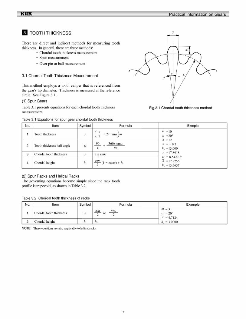
This method employs a tooth caliper that is referenced from the gear's tip diameter. Thickness is measured at the reference circle. See Figure 3.1.(1) Spur Gears
Table 3.1 presents equations for each chordal tooth thicknessmeasurement.
3 TOOTH THICKNESS
No.
2
Table 3.1 Equations for spur gear chordal tooth thickness
1
z m sinψ
(1 - cosψ) + ha
+
Formula
3
4
Item
Tooth thickness
Tooth thickness half angle
Chordal tooth thickness
Chordal height
Symbol
s
ψ
s
ha
+ 2x tanα m =10 =20° =12 = + 0.3 =13.000 =17.8918 = 8.54270° =17.8256 =13.6657
mαzxha
sψsha
(2) Spur Racks and Helical RacksThe governing equations become simple since the rack tooth profile is trapezoid, as shown in Table 3.2.
ExampleNo.
2
Table 3.2 Chordal tooth thickness of racks
1
ha
FormulaItem
Chordal tooth thickness
Chordal height
Symbol
s
ha
or= 3= 20°= 4.7124= 3.0000
mαsha
NOTE: These equations are also applicable to helical racks.
Fig.3.1 Chordal tooth thickness method
s
h adψ
2z m
z90
2π
π z360x tanα
2πm
2πmn
Practical Information on Gears
8
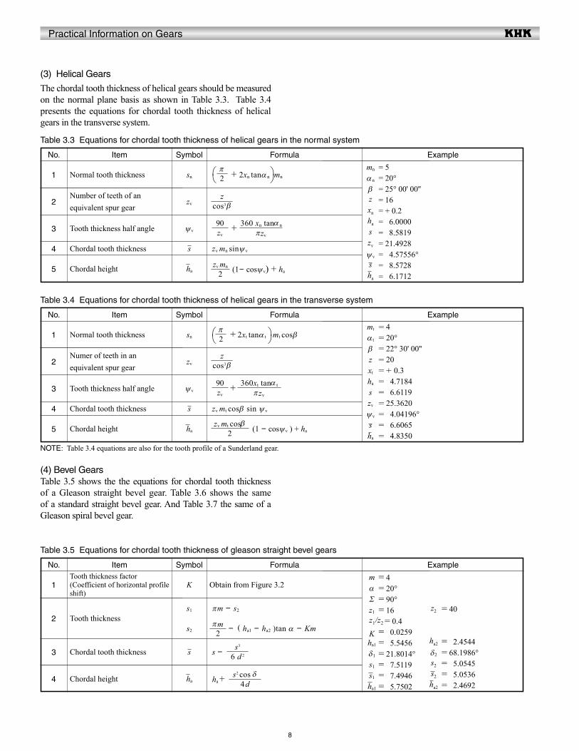
(3) Helical Gears
The chordal tooth thickness of helical gears should be measured on the normal plane basis as shown in Table 3.3. Table 3.4 presents the equations for chordal tooth thickness of helical gears in the transverse system.
ExampleNo.
2
Table 3.3 Equations for chordal tooth thickness of helical gears in the normal system
1
+
zv mn sinψ v
(1- cosψv) + ha
Formula
3
4
5
Item
Normal tooth thickness
Number of teeth of an equivalent spur gear
Tooth thickness half angle
Chordal tooth thickness
Chordal height
Symbol
sn
zv
ψv
s
ha
+ 2xn tanα n mn
= 5= 20°= 25° 00' 00''= 16= + 0.2= 06.0000= 08.5819= 21.4928= 04.57556°= 08.5728= 06.1712
mn
αn
βzxn
ha
szv
ψv
sha
ExampleNo.
2
Table 3.4 Equations for chordal tooth thickness of helical gears in the transverse system
1
+
zv mt cosβ sin ψ v
(1 - cosψv ) + ha
Formula
3
4
5
Item
Normal tooth thickness
Numer of teeth in an equivalent spur gear
Tooth thickness half angle
Chordal tooth thickness
Chordal height
Symbol
sn
zv
ψv
s
ha
+ 2xt tanα t mt cosβ= 4= 20°= 22° 30' 00''= 20= + 0.3= 04.7184= 06.6119= 25.3620= 04.04196°= 06.6065= 04.8350
mt
α t
βzxt
ha
szv
ψv
sha
NOTE: Table 3.4 equations are also for the tooth profile of a Sunderland gear.
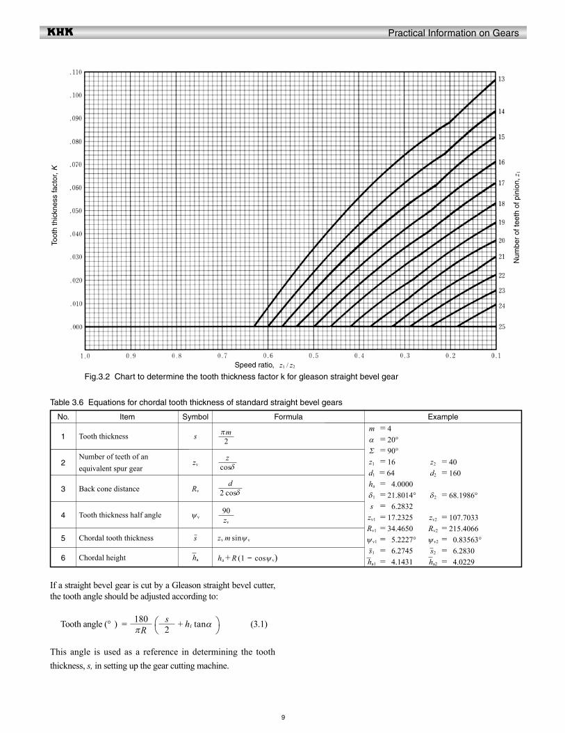
(4) Bevel GearsTable 3.5 shows the the equations for chordal tooth thickness of a Gleason straight bevel gear. Table 3.6 shows the same of a standard straight bevel gear. And Table 3.7 the same of a Gleason spiral bevel gear.
ExampleNo.
2
Table 3.5 Equations for chordal tooth thickness of gleason straight bevel gears
1
s -
ha +
πm - s2
- ( ha1 - ha2 )tan α - Km
Formula
3
4
ItemTooth thickness factor (Coefficient of horizontal profile shift)
Tooth thickness
Chordal tooth thickness
Chordal height
Symbol
K
s1
s2
s
ha
Obtain from Figure 3.2= 4= 20°= 90°= 16 = 0.4= 00.0259= 05.5456= 21.8014°= 07.5119= 07.4946= 05.7502
= 40
= 02.4544= 68.1986°= 05.0545= 05.0536= 02.4692
mαΣz1
Kha1
δ1
s1
s1
ha1
z2
ha2
δ2
s2
s2
ha2
z1/z2
2π
πzv
360 xn tanα n
zv
90
2zv mn
cos3 βz
2π
cos3 βz
πzv
360xt tanα t
zv
90
2zv mt cosβ
2πm
6 d 2
s3
4 ds2 cos δ
Practical Information on Gears
5
9
ExampleNo.
2
Table 3.6 Equations for chordal tooth thickness of standard straight bevel gears
1
zv m sinψ v
ha +R (1 - cosψ v)
Formula
3
4
6
Item
Tooth thickness
Number of teeth of an equivalent spur gear
Back cone distance
Tooth thickness half angle
Chordal tooth thickness
Chordal height
Symbol
s
zv
Rv
ψv
s
ha
= 4= 20°= 90°= 16
= 64= 04.0000= 21.8014°= 06.2832= 17.2325= 34.4650= 25.2227°= 06.2745= 04.1431
= 40= 160
= 68.1986°
= 107.7033= 215.4066= 00.83563°= 06.2830= 04.0229
mαΣz1
d1
ha
δ1
szv1
Rv1
ψv1
s1
ha1
z2
d2
δ2
zv2
Rv2
ψv2
s2
ha2
If a straight bevel gear is cut by a Gleason straight bevel cutter, the tooth angle should be adjusted according to:
Tooth angle (° ) = + hf tanα (3.1)
This angle is used as a reference in determining the tooth thickness, s, in setting up the gear cutting machine.
2πm
cosδz
2 cosδd
zv
90
πR180
2s
Fig.3.2 Chart to determine the tooth thickness factor k for gleason straight bevel gearSpeed ratio, z1 / z2
Num
ber
of te
eth
of p
inio
n, z 1
Toot
h th
ickn
ess
fact
or, K
Practical Information on Gears
10
ExampleNo.
2
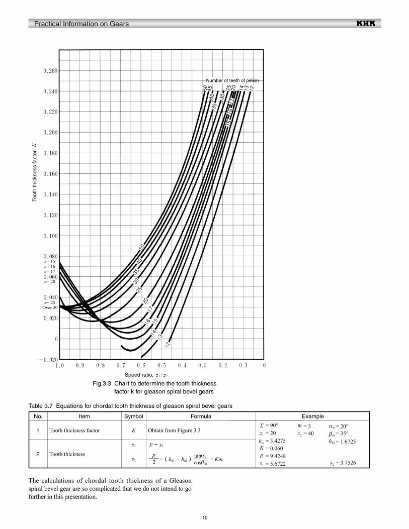
Table 3.7 Equations for chordal tooth thickness of gleason spiral bevel gears
1
- ( ha1 - ha2 ) - Km
p - s2
FormulaItem
Tooth thickness factor
Tooth thickness
Symbol
K
s2
s1
Obtain from Figure 3.3= 90°= 20= 3.4275= 0.060= 9.4248= 5.6722
= 1.6725
= 3.7526
= 3= 40
= 20°= 35°
Σz1
ha1
Kps1
ha2
s2
mz2
αn
βm
The calculations of chordal tooth thickness of a Gleason spiral bevel gear are so complicated that we do not intend to go further in this presentation.
Speed ratio, z1 / z2
Toot
h th
ickn
ess
fact
or.
K
Number of teeth of pinion
z= 15z= 16z= 17
z= 20
z= 25Over 30
Fig.3.3 Chart to determine the tooth thickness factor k for gleason spiral bevel gears
2p
cosβm
tanαn
Practical Information on Gears
11
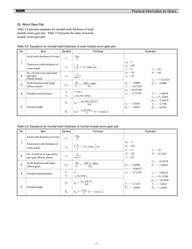
(5) Worm Gear Pair
Table 3.8 presents equations for chordal tooth thickness of axial module worm gear pair. Table 3.9 presents the same of normal module worm gear pair.
ExampleNo.
2
Table 3.8 Equations for chordal tooth thickness of axial module worm gear pair
1
+
st1 cos γzv mt cosγ sinψv2
ha1 +
ha2 + (1 - cosψv2)
Formula
3
4
5
Item
Axial tooth thickness of worm
Transverse tooth thickness of worm wheel
No. of teeth in an equivalent spur gear(Worm wheel)
Tooth thickness half angle (Worm wheel)
Chordal tooth thickness
Chordal height
Symbol
st1
st2
zv2
ψv2
s1
s2
ha1
ha2
+ 2xt2 tanα t mt
= 3= 20°= 2= 38= 65
= 03.0000= 08.97263°= 20.22780°= 04.71239
= 04.6547= 03.0035
= 30= 90
= + 0.33333= 04.0000
= 05.44934= 31.12885= 03.34335°= 05.3796= 04.0785
mt
α n
z1
d1
a
ha1
γα t
st1
s1
ha1
z2
d2
xt2
ha2
st2
zv2
ψ v2
s2
ha2
ExampleNo.
2
Table 3.9 Equations for chordal tooth thickness of normal module worm gear pair
1
+
sn1
zv2 mn sinψ v2
ha1 +
ha2 + (1 - cosψ v2)
Formula
3
4
5
Item
Axial tooth thickness of worm
Transverse tooth thickness of worm wheel
No. of teeth in an equivalent spur gear (Worm wheel)
Tooth thickness half angle (Worm gear)
Chordal tooth thickness
Chordal height
Symbol
sn1
sn2
zv2
ψv2
s1
s2
ha1
ha2
+ 2xn2 tanα n mn
= 3= 20°= 2= 38= 65
= 03.0000= 09.08472°= 04.71239
= 04.7124= 03.0036
= 30= 91.1433
= 00.14278= 03.42835
= 05.02419= 31.15789= 03.07964°= 05.0218= 03.4958
mn
α n
z1
d1
a
ha1
γsn1
s1
ha1
z2
d2
xn2
ha2
sn2
zv2
ψ v2
s2
ha2
2πmt
2π
cos 3 γz2
πzv2
360 xt2 tanα tzv2
90
4 d 1
(st1 sin γ cos γ) 2
2zv mt cos γ
2πmn
2π
cos 3 γz2
πzv2
360 xn2 tanα nzv2
90
4 d 1
(sn1 sin γ ) 2
2zv mn

Practical Information on Gears
= 3 ,= 25° 00' 00''= + 0.4= 21.88023°= 04.63009= 05= 42.0085
= 20° , = 24
12
3.2 Span Measurement of Teeth
Span measurement of teeth, W, is a measure over a number of teeth, k, made by means of a special tooth thickness micrometer. The value measured is the sum of normal tooth thickness on the base circle, sbn, and normal pitch, pbn (k – 1). See Figure 3.4.
(1) Spur and Internal GearsThe applicable equations are presented in Table 3.10.
ExampleNo.
2
Table 3.10 Span measurement of spun and internal gear teeth
1
m cosα {π (k - 0.5) + z invα} + 2xm sinα
FormulaItem
Span number of teeth
Span measurement over k teeth
Symbol
k
W
kth = z K ( f ) + 0.5 See NOTE
Select the nearest natural number of zmth as zm
= 3= 20°= 24= + 0.4= 03.78787= 04= 32.8266
mαzxkth
kW
ExampleNo.
2
Table 3.11 Equations for span measurement of the normal system helical gears
1
mn cosα n {π(k - 0.5 )+ z invα t } +2xn mn sinα n
FormulaItem
Span number of teeth
Span measurement over k teeth
Symbol
k
W
kth = z K ( f ,β ) + 0.5 See NOTE
Select the nearest natural number of zmth as zm
mn
βxn
α tkth
kW
αn z
NOTE: K ( f ) = {secα (1+2 f ) 2 - cos2α -invα-2 f tanα} (3.2)
where f =
Figure 3.4 shows the span measurement of a spur gear. This measurement is on the outside of the teeth.For internal gears the tooth profile is opposite to that of the external spur gear. Therefore, the measurement is between the inside of the tooth profiles.
(2) Helical Gears
Tables 3.11 and 3.12 present equations for span measurement of the normal and the transverse systems, respectively, of helical gears.
NOTE:
K ( f ,β ) = 1 + (cos2β + tan2α n ) (secβ + 2 f )2 - 1 - invα t - 2 f tanα n (3.3)
where f =
π1
π1
cos2β + tan2α n
sin2β
zxn
W
d
Fig.3.4 Span measurement over k teeth (spur gear)
zx
Practical Information on Gears
13
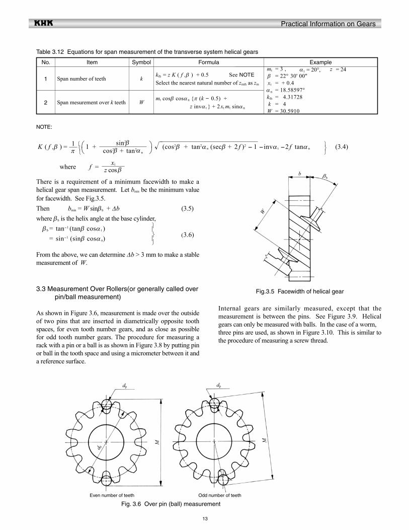
There is a requirement of a minimum facewidth to make a helical gear span measurement. Let bmin be the minimum value for facewidth. See Fig.3.5. Then bmin = W sinβb + Δb (3.5) where βb is the helix angle at the base cylinder, β b = tan-1 (tanβ cosα t ) = sin-1 (sinβ cosα n)
From the above, we can determine Δb > 3 mm to make a stable measurement of W.
Internal gears are similarly measured, except that the measurement is between the pins. See Figure 3.9. Helical gears can only be measured with balls. In the case of a worm,three pins are used, as shown in Figure 3.10. This is similar to the procedure of measuring a screw thread.
ExampleNo.
2
Table 3.12 Equations for span measurement of the transverse system helical gears
1
mt cosβ cosα n {π (k - 0.5) +z invα t } + 2xt mt sinα n
FormulaItem
Span number of teeth
Span mesurement over k teeth
Symbol
k
W
kth = z K ( f ,β ) + 0.5 See NOTE
Select the nearest natural number of zmth as zm
NOTE:
K ( f ,β ) = 1 + (cos2β + tan2α n (secβ + 2 f )2 - 1 -invα t -2 f tanα n (3.4) where f =
(3.6)
3.3 Measurement Over Rollers(or generally called over pin/ball measurement)
As shown in Figure 3.6, measurement is made over the outside of two pins that are inserted in diametrically opposite tooth spaces, for even tooth number gears, and as close as possible for odd tooth number gears. The procedure for measuring a rack with a pin or a ball is as shown in Figure 3.8 by putting pin or ball in the tooth space and using a micrometer between it and a reference surface.
= 3 ,= 22° 30' 00''= + 0.4= 18.58597°= 04.31728= 04= 30.5910
= 20°, = 24mt
βxt
α n
kth
kW
α t z
π1
cos2β + tan2α n
sin2β
z cos βxt
Fig.3.5 Facewidth of helical gear
b βb
W
Fig. 3.6 Over pin (ball) measurement
dp dp
d 0
M M
Even number of teeth Odd number of teeth

Practical Information on Gears
14
(1) Spur GearsIn measuring a standard gear, the size of the pin must meet the condition that its surface should have the tangent point at the standard pitch circle. While, in measuring a shifted gear, the surface of the pin should have the tangent point at the d + 2xm circle.
ExampleNo.
2
Table 3.13 Equations for calculating ideal pin diameters
1
tanα ' + η
z m cosα (invφ + η)
cos- 1
Formula
3
4
Item
Spacewidth half angle
Pressure angle at the point pin is tangent to tooth surface
Pressure angle at pin center
Ideal pin diameter
Symbol
η
α '
φ
d'p
- invα -= 1= 20°= 20= 0= 0.0636354= 20°= 0.4276057= 1.7245
mαzxηα 'φd'p
ExampleNo.
2
Table 3.14 Equations for over pins measurement for spur gears
1
Find from involute function table
Even teeth + dp
Odd teeth cos + dp
- + invα +
Formula
3
4
Item
Pin diameter
Involute function φ
Pressure angle at pin center
Measurement over pin (ball)
Symbol
dp
inv φ
φ
M
NOTE 1
= 1.7= 0.0268197= 24.1350°= 22.2941
dp
invφ
φ
M
NOTE: The units of angles η and φ are radians.
The ideal diameters of pins when calculated from the equations of Table 3.13 may not be practical. So, in practice, we select a standard pin diameter close to the ideal value. After the actual diameter of pin dp is determined, the over pin measurement M can be calculated from Table 3.14.
NOTE: The value of the ideal pin diameter from Table 3.13, or its approximate value, is applied as the actual diameter of pin dp here.
2 zπ
z
2x tanα
( z + 2x) m
z m cosα
z mcosαdp
2zπ
z2x tanα
cos φz m cosα
cos φz m cosα
z90°
dp
Fig.3.7 Over pins measurement of spur gear
φ
tan α '
α '
inv φ
η
inv α
d b dd +
2xm
M
Practical Information on Gears
Number of teeth z
010020030040050
060070080090100
110120130140150
160170180190200
15
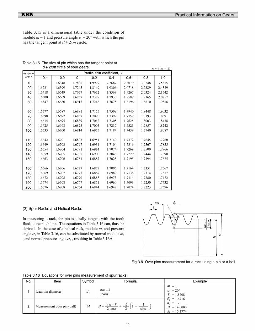
Table 3.15 is a dimensional table under the condition of module m = 1 and pressure angle α = 20° with which the pin has the tangent point at d + 2xm circle.
Profile shift coefficient, x- 0.4 - 0.2 0 0.2 0.4 0.6 0.8 1.0
1.62311.64181.65001.6547
1.65771.65981.66141.66251.6635
1.66421.66491.66541.66591.6663
1.66661.66691.66721.66741.6676
1.63481.65991.66491.66691.6680
1.66871.66921.66951.66981.6700
1.67011.67031.67041.67051.6706
1.67061.67071.67081.67081.6708
1.78861.72451.70571.69671.6915
1.68811.68571.68391.68251.6814
1.68051.67971.67911.67851.6781
1.67771.67731.67701.67671.6764
1.99791.81491.76321.73891.7248
1.71551.70901.70421.70051.6975
1.69511.69311.69141.69001.6887
1.68771.68671.68581.68511.6844
2.26871.93061.83691.79301.7675
1.75091.73921.73051.72371.7184
1.71401.71041.70741.70481.7025
1.70061.69891.69731.69601.6947
2.60792.07181.92671.85891.8196
1.79401.77591.76251.75211.7439
1.73721.73161.72691.72291.7195
1.71641.71381.71141.70931.7074
3.02482.23892.03241.93651.8810
1.84481.81931.80031.78571.7740
1.76451.75671.75001.74441.7394
1.73511.73141.72801.72501.7223
3.53152.43292.15422.02571.9516
1.90321.86911.84381.82421.8087
1.79601.78551.77661.76901.7625
1.75671.75171.74721.74321.7396
m = 1 , α = 20°
Table 3.15 The size of pin which has the tangent point at d + 2xm circle of spur gears
(2) Spur Racks and Helical Racks
In measuring a rack, the pin is ideally tangent with the tooth flank at the pitch line. The equations in Table 3.16 can, thus, be derived. In the case of a helical rack, module m, and pressure angle α, in Table 3.16, can be substituted by normal module mn
, and normal pressure angle αn , resulting in Table 3.16A.
ExampleNo.
2
Table 3.16 Equations for over pins measurement of spur racks
1
H - + 1 +
FormulaItem
Ideal pin diameter
Measurement over pin (ball)
Symbol
d'p
M
= 1= 20°= 1.5708= 1.6716= 1.7= 14.0000= 15.1774
mαs
d'pdp
HM
cosαπm - s
2 tanαπm - s
2dp
sinα
1
dp
Fig.3.8 Over pins measurement for a rack using a pin or a ball
πms
MH
2 ta
nαπm
- s
Practical Information on Gears
16
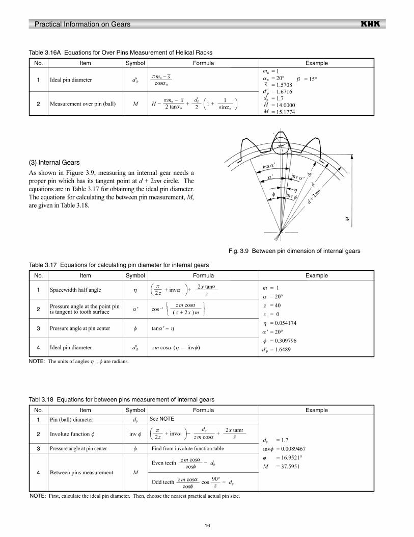
(3) Internal Gears
As shown in Figure 3.9, measuring an internal gear needs a proper pin which has its tangent point at d + 2xm circle. The equations are in Table 3.17 for obtaining the ideal pin diameter. The equations for calculating the between pin measurement, M, are given in Table 3.18.
ExampleNo.
2
Table 3.16A Equations for Over Pins Measurement of Helical Racks
1
H - + 1 +
FormulaItem
Ideal pin diameter
Measurement over pin (ball)
Symbol
d'p
M
ExampleNo.
2
Table 3.17 Equations for calculating pin diameter for internal gears
1
tanα ' - η
z m cosα (η - invφ)
cos -1
Formula
3
4
Item
Spacewidth half angle
Pressure angle at the point pin is tangent to tooth surface
Pressure angle at pin center
Ideal pin diameter
Symbol
η
α '
φ
d'p
+ invα + = 1= 20°= 40= 0= 0.054174= 20°= 0.309796= 1.6489
mα
zxη
α 'φ
d'p
NOTE: The units of angles η , φ are radians.
ExampleNo.
2
Tabl 3.18 Equations for between pins measurement of internal gears
1
Find from involute function table
Even teeth - dp
Odd teeth cos - dp
+ invα - +
Formula
3
4
Item
Pin (ball) diameter
Involute function φ
Pressure angle at pin center
Between pins measurement
Symbol
dp
inv φ
φ
M
See NOTE
= 1.7= 0.0089467= 16.9521°= 37.5951
dp
invφ
φ
M
NOTE: First, calculate the ideal pin diameter. Then, choose the nearest practical actual pin size.
= 1= 20°= 1.5708= 1.6716= 1.7= 14.0000= 15.1774
mn
αns
d'pdpHM
= 15°βcosαn
πmn - s
2 tanαn
πmn - s2dp
sinαn
1
2 zπ
z
2x tanα
( z + 2x ) m
z m cosα
z m cosαdp
2zπ
z2x tanα
cosφz m cosα
cosφz m cosα
z90°
Fig. 3.9 Between pin dimension of internal gears
φ
tan α '
α '
inv φη
inv α ' d bd
d + 2xm
M
Practical Information on Gears
17
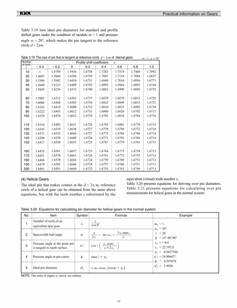
Table 3.19 lists ideal pin diameters for standard and profile shifted gears under the condition of module m = 1 and pressure angle α = 20°, which makes the pin tangent to the reference circle d + 2xm.
equivalent (virtual) teeth number zv.Table 3.20 presents equations for deriving over pin diameters. Table 3.21 presents equations for calculating over pin measurements for helical gears in the normal system.
(4) Helical Gears
The ideal pin that makes contact at the d + 2xn mn reference circle of a helical gear can be obtained from the same above equations, but with the teeth number z substituted by the
Number of teeth
z
010020030040050
060070080090100
110120130140150
160170180190200
Profile shift coefficient, x- 0.4 - 0.2 0 0.2 0.4 0.6 0.8 1.0
- 1.46871.53091.56401.5845
1.59851.60861.61621.62221.6270
1.63101.63431.63711.63961.6417
1.64351.64511.64661.64791.6491
1.47891.56041.59421.61231.6236
1.63121.63681.64101.64431.6470
1.64921.65101.65251.65391.6550
1.65611.65701.65781.65851.6591
1.59361.62841.64181.64891.6533
1.65621.65831.66001.66121.6622
1.66311.66381.66441.66491.6653
1.66571.66611.66641.66661.6669
1.67581.67591.67511.67451.6740
1.67371.67341.67321.67311.6729
1.67281.67271.67271.67261.6725
1.67251.67241.67241.67241.6723
1.72831.70471.69491.68951.6862
1.68391.68221.68101.68001.6792
1.67851.67791.67751.67711.6767
1.67641.67611.67591.67571.6755
1.75191.71541.70161.69441.6900
1.68701.68491.68331.68201.6810
1.68011.67941.67881.67831.6779
1.67751.67721.67681.67661.6763
1.74601.70841.69561.68931.6856
1.68321.68151.68021.67921.6784
1.67781.67721.67681.67641.6761
1.67581.67551.67531.67511.6749
1.70921.68371.67711.67441.6732
1.67251.67211.67181.67171.6716
1.67151.67141.67141.67141.6713
1.67131.67131.67131.67131.6713
m = 1 , α = 20°Table 3.19 The size of pin that is tangent at reference circle d + 2xm of internal gears
5
ExampleNo.
2
Table 3.20 Equations for calculating pin diameter for helical gears in the normal system
1
cos-1
tanα 'v + ηv
zv mn cosα n (invφv + η v)
- inv αn -
Formula
3
4
Item
Number of teeth of an equivalent spur gear
Spacewidth half angle
Pressure angle at the point pin is tangent to tooth surface
Pressure angle at pin center
Ideal pin diameter
Symbol
zv
η v
α 'v
φv
d'p
= 1= 20°= 20= 15° 00' 00''
= + 0.4= 22.19211= 00.0427566= 24.90647°= 00.507078= 01.9020
mn
α n
zβxn
zv
η v
α 'vφv
d'p
NOTE: The units of angles ηv and φv are radians.
cos3 βz
2zv
πzv
2xn tanαn
zv+2xn
zv cosα n
Practical Information on Gears
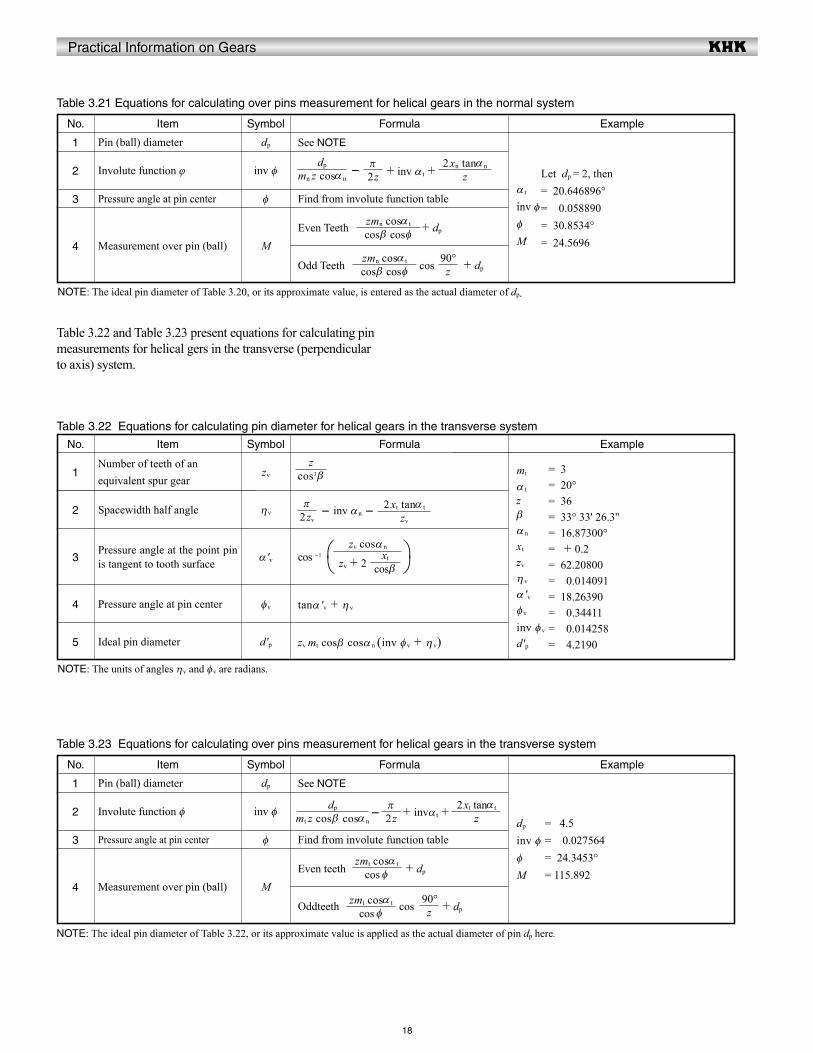
18
ExampleNo.
2
Table 3.21 Equations for calculating over pins measurement for helical gears in the normal system
1
Find from involute function table
Even Teeth + dp
Odd Teeth cos + dp
- + inv α t +
Formula
3
4
Item
Pin (ball) diameter
Involute function φ
Pressure angle at pin center
Measurement over pin (ball)
Symbol
dp
inv φ
φ
M
See NOTE
Let dp = 2, then = 20.646896°= 00.058890= 30.8534°= 24.5696
α t
inv φφ
M
NOTE: The ideal pin diameter of Table 3.20, or its approximate value, is entered as the actual diameter of dp.
Table 3.22 Equations for calculating pin diameter for helical gears in the transverse system
Table 3.22 and Table 3.23 present equations for calculating pin measurements for helical gers in the transverse (perpendicular to axis) system.
5
ExampleNo.
2
1
cos -1
tanα 'v + η v
zv mt cosβ cosα n (inv φv + η v)
- inv αn -
Formula
3
4
Item
Number of teeth of an equivalent spur gear
Spacewidth half angle
Pressure angle at the point pin is tangent to tooth surface
Pressure angle at pin center
Ideal pin diameter
Symbol
zv
ηv
α 'v
φv
d'p
= 3= 20°= 36= 33° 33' 26.3''= 16.87300°= + 0.2= 62.20800= 00.014091= 18.26390= 00.34411= 00.014258= 04.2190
mt
α t
zβα n
xt
zv
η v
α 'vφv
inv φv
d'p
ExampleNo.
2
Table 3.23 Equations for calculating over pins measurement for helical gears in the transverse system
1
Find from involute function table
Even teeth + dp
Oddteeth cos + dp
- + invα t +
Formula
3
4
Item
Pin (ball) diameter
Involute function φ
Pressure angle at pin center
Measurement over pin (ball)
Symbol
dp
inv φ
φ
M
See NOTE
=0 4.5= 0 0.027564=024.3453°= 115.892
dp
inv φφ
M
NOTE: The ideal pin diameter of Table 3.22, or its approximate value is applied as the actual diameter of pin dp here.
mn z cosα n
dp
2zπ
z2xn tanα n
cos β cos φzmn cosα t
z90°
cos β cos φzmn cosα t
cos3 βz
2zv
πzv
2xt tanα t
zv + 2zv cosα n
cos β
xt
mt z cos β cosα n
dp
2zπ
z2xt tanα t
cos φzmt cosα t
z90°
cos φzmt cosα t
NOTE: The units of angles ηv and φv are radians.

Practical Information on Gears
19
(5) Three Wire Method of Worm Measurement
The teeth profile of type III worms which are most popular are cut by standard cutters with a pressure angle αn = 20°. This results in the normal pressure angle of the worm being a bit smaller than 20°. The equation below shows how to calculate a type III worm in an AGMA system.
αn = α0 - sin3γ (3.7)
where r : Worm reference radius r0 : Cutter radius z1 : Number of threads γ : Lead angle of worm
The exact equation for a three wire method of type III worm is not only difficult to comprehend, but also hard to calculate precisely. We will introduce two approximate calculation methods here:(a) Regard the tooth profile of the worm as a straight
tooth profile of a rack and apply its equations.
Using this system, the three wire method of a worm can be calculated by Table 3.24.
ExampleNo.
2
Table 3.24 Equations for three wire method of worm measurement, (a)-1
1
d1 - + dp 1 +
FormulaItem
Ideal pin diameter
Three wire measuremnt
Symbol
d'p
M
= 2= 1= 03.691386°= 20.03827°= 03.3440Let dp be 03.3 = 35.3173
= 20°= 31
mx
z1
γα x
d'pdp
M
αn
d1
These equations presume the worm lead angle to be very small and can be neglected. Of course, as the lead angle gets larger, the equations' error gets correspondingly larger. If the lead angle is considered as a factor, the equations are as in Table 3.25.
ExampleNo.
2
Table 3.25 Equations for three wire method of worm measurement, (a)-2
1
d1 - + dp 1 +
-
FormulaItem
Ideal pin diameter
Three wire measurement
Symbol
d'p
M
z1
90r0 cos2 γ + r
r
2cosα x
πmx
2cosα n
πmn
2 tanα x
πmx
sinα x
1
2 tanα n
πmn
sinα n
1
2d1
(dp cosα n sin γ )2
= 2= 1= 03.691386°= 01.99585= 03.3363Let dp be 03.3 = 35.3344
= 20°= 31
mx
z1
γmn
d'pdp
M
αn
d1
Fig.3.10 Three wire method of a worm
dp
d M
Practical Information on Gears
20
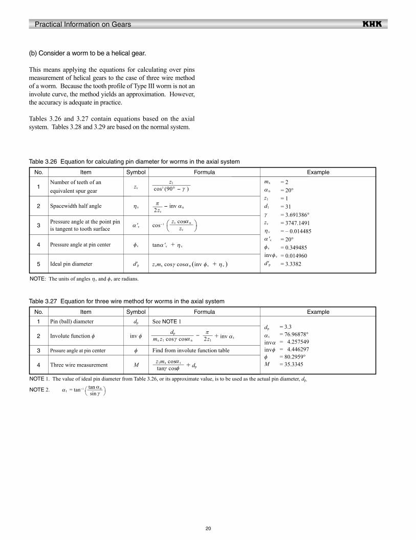
(b) Consider a worm to be a helical gear.
This means applying the equations for calculating over pins measurement of helical gears to the case of three wire method of a worm. Because the tooth profile of Type III worm is not an involute curve, the method yields an approximation. However, the accuracy is adequate in practice.
Tables 3.26 and 3.27 contain equations based on the axial system. Tables 3.28 and 3.29 are based on the normal system.
Table 3.26 Equation for calculating pin diameter for worms in the axial system
5
ExampleNo.
2
1
cos-1
tanα 'v + η v
zvmx cosγ cosα n (inv φv + η v )
- inv αn
Formula
3
4
Item
Number of teeth of an equivalent spur gear
Spacewidth half angle
Pressure angle at the point pin is tangent to tooth surface
Pressure angle at pin center
Ideal pin diameter
Symbol
zv
ηv
α 'v
φv
d'p
= 2= 20°= 1= 31= 3.691386°= 3747.1491= – 0.014485= 20°= 0.349485= 0.014960= 3.3382
mx
α n
z1
d1
γzv
η v
α 'vφv
invφv
d'p
ExampleNo.
2
Table 3.27 Equation for three wire method for worms in the axial system
1
Find from involute function table
+ dp
- + inv α t
Formula
3
4
Item
Pin (ball) diameter
Involute function φ
Prssure angle at pin center
Three wire measurement
Symbol
dp
inv φ
φ
M
See NOTE 1= 3.3= 76.96878°= 04.257549= 04.446297= 80.2959°= 35.3345
dp
α t
invαinvφφM
NOTE 1. The value of ideal pin diameter from Table 3.26, or its approximate value, is to be used as the actual pin diameter, dp.
NOTE 2. α t = tan-1
cos3 (90° - γ )
z1
2zv
π
zv
zv cosα n
mx z1 cos γ cosα n
dp
2z1
π
tanγ cosφz1mx cosα t
sin γtan αn
NOTE: The units of angles ηv and φv are radians.
Practical Information on Gears
21
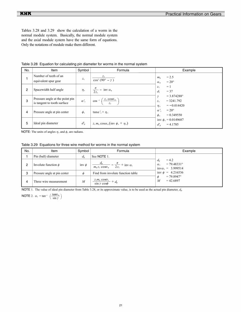
Tables 3.28 and 3.29 show the calculation of a worm in the normal module system. Basically, the normal module system and the axial module system have the same form of equations. Only the notations of module make them different.
Table 3.28 Equation for calculating pin diameter for worms in the normal system
5
ExampleNo.
2
1
cos -1
tanα 'v + η v
zv mn cosα n (inv φv + η v)
- inv αn
Formula
3
4
Item
Number of teeth of an equivalent spur gear
Spacewidth half angle
Pressure angle at the point pin is tangent to tooth surface
Pressure angle at pin center
Ideal pin diameter
Symbol
zv
ηv
α 'v
φv
d'p
= 2.5= 20°= 1= 37= 3.874288°
= 3241.792 = -0.014420= 20°= 0.349550= 0.0149687= 4.1785
mn
α n
z1
d1
γzv
η v
α 'vφv
inv φv
d'p
ExampleNo.
2
Table 3.29 Equations for three wire method for worms in the normal system
1
Find from involute function table
+ dp
- + inv α t
Formula
3
4
Item
Pin (ball) diameter
Involute function φ
Pressure angle at pin center
Three wire measurement
Symbol
dp
inv φ
φ
M
See NOTE 1.= 4.2= 79.48331°= 03.999514= 04.216536= 79.8947°= 42.6897
dp
α t
invα t
inv φφM
NOTE 1. The value of ideal pin diameter from Table 3.28, or its approximate value, is to be used as the actual pin diameter, dp.
NOTE 2. α t = tan-1
cos3 (90° - γ ) z1
2zv
π
zv
zv cosα n
mn z1 cosα n
dp
2z1
π
sin γ cosφz1mn cosα t
sin γtanαn
NOTE: The units of angles ηv and φv are radians.
Practical Information on Gears
4
5
22
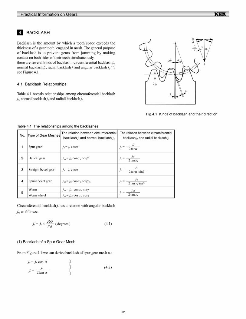
Backlash is the amount by which a tooth space exceeds the thickness of a gear tooth engaged in mesh. The general purpose of backlash is to prevent gears from jamming by making contact on both sides of their teeth simultaneously.there are several kinds of backlash: circumferential backlash jt , normal backlash jn , radial backlash jr and angular backlash jθ (°), see Figure 4.1.
4.1 Backlash Relationships
Table 4.1 reveals relationships among circumferential backlash jt , normal backlash jn and radiall backlash jr .
4 BACKLASH
Circumferential backlash jt has a relation with angular backlash jθ , as follows:
jθ = jt × ( degrees ) (4.1)
(1) Backlash of a Spur Gear Mesh
From Figure 4.1 we can derive backlash of spur gear mesh as:
jn = jt cos α
jr =
No.
2
Table 4.1 The relationships among the backlashes
1
jr =
jr =
jr =
jr =
The relation between circumferential backlash jt and radial backlash jr
3
Type of Gear Meshes
Spur gear
Helical gear
Straight bevel gear
Spiral bevel gear
Worm
Worm wheel
The relation between circumferential backlash jt and normal backlash jn
jn = jt cosα
jnn = jtt cosα n cosβ
jn = jt cosα
jnn = jtt cosα n cosβm
jnn = jtt1 cosα n sinγ
jnn = jtt2 cosα n cosγ
jr =
(4.2)
2 tanα x
jtt2
2 tanα t sinδjtt
2 tanα sinδjt
2 tanα t
jtt
2 tanαjt
2tan αjt
πd360
Fig.4.1 Kinds of backlash and their direction
jr
jn
jt
2 jr
αjθ
α
2jt
2jn
Practical Information on Gears
23
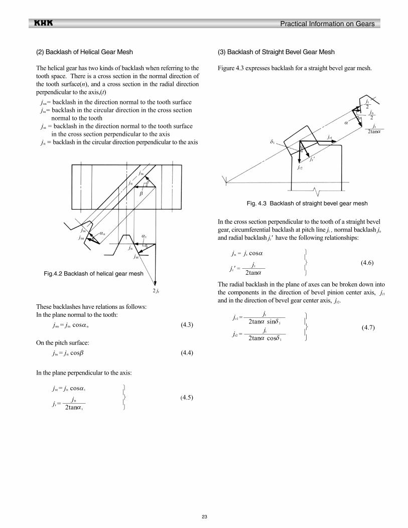
(2) Backlash of Helical Gear Mesh
The helical gear has two kinds of backlash when referring to the tooth space. There is a cross section in the normal direction of the tooth surface(n), and a cross section in the radial direction perpendicular to the axis,(t) jnn= backlash in the direction normal to the tooth surface jtn= backlash in the circular direction in the cross section normal to the tooth jnt = backlash in the direction normal to the tooth surface in the cross section perpendicular to the axis jtt = backlash in the circular direction perpendicular to the axis
(3) Backlash of Straight Bevel Gear Mesh
Figure 4.3 expresses backlash for a straight bevel gear mesh.
In the cross section perpendicular to the tooth of a straight bevel gear, circumferential backlash at pitch line jt , normal backlash jn and radial backlash jr' have the following relationships:
jn = jt cosα
jr' =
The radial backlash in the plane of axes can be broken down into the components in the direction of bevel pinion center axis, jr1
and in the direction of bevel gear center axis, jr2.
jr1 =
jr2 =
These backlashes have relations as follows:In the plane normal to the tooth: jnn = jtn cosα n (4.3)
On the pitch surface: jtn = jtt cosβ (4.4)
In the plane perpendicular to the axis:
jnt = jtt cosα t
jr =
(4.5)
(4.6)
(4.7)
2tanα t
jtt
2tanαjt
2tanα sinδ 1
jt
2tanα cosδ 1
jt
Fig.4.2 Backlash of helical gear mesh
Fig. 4.3 Backlash of straight bevel gear mesh
jnt
αn
2 jr
jtt
jnn
jtn
jtn
jtt
α t
β
α
jr2
2jt
2jn
jr1δ1
2tanαjt
jr'

Practical Information on Gears
24
(4) Backlash of a Spiral Bevel Gear Mesh
Figure 4.4 delineates backlash for a spiral bevel gear mesh.
In the tooth space cross section normal to the tooth: jnn = jtn cosα n (4.8)On the pitch surface jtn= jtt cosβm (4.9)In the plane perpendicular to the generatrix of the pitch cone: jnt = jtt cosα t
jr' =
The transverse backlash in the plane of axes jr' can be broken down into the components in the direction of bevel pinion center axis, jr1, and in the direction of bevel gear center axis, jr2.
jr1 =
jr2 =
(5) Backlash of Worm Gear Pair Mesh
Figure 4.5 expresses backlash for a worm gear pair mesh.
On the pitch surface of a worm: jtn = jtt1 sinγ jtn = jtt2 cosγ
tan γ =
In the cross section of a worm perpendicular to its axis:
jnt1 = jtt1 cosα t
jr =
In the plane perpendicular to the axis of the worm wheel:
jnt2 = jtt2 cosα x
jr =
(4.10)
(4.11)
(4.12)
(4.13)
2 tanα t
jtt
2 tan α t sin δ 1
jtt
2 tan α t cos δ 1
jtt
jtt1
jtt2
2 tanα t
jtt1
2 tanα x
jtt2
(4.14)
Fig.4.4 Backlash of spiral bevel gear mesh
Fig.4.5 Backlash of worm gear pair
α t
jr2
2jtt
2jnt
jr1δ1
2tan αjtt
αn
jtnjnnjtt
jtn βm
αx
2 jr
jtt2
jnt2
jtt1
jtt2
jtn
jtt1
jnt1
α t
2 jr
γ
jr'
Practical Information on Gears
25
4.2 Tooth Thickness and Backlash
There are two ways to produce backlash. One is to enlarge the center distance. The other is to reduce the tooth thickness. The latter is much more popular than the former. We are going to discuss more about the way of reducing the tooth thickness.
In SECTION 3, we have discussed the standard tooth thickness s1 and s2. In the meshing of a pair of gears, if the tooth thickness of pinion and gear were reduced by Δs1 and Δs2, they would produce a backlash of Δs1 and Δs2 in the direction of the pitch circle. Let the magnitude of Δs1 and Δs2 be 0.1. We know that α = 20° , then: jt = Δs1 + Δs2
= 0.1+ 0.1 = 0.2We can convert it into the backlash on normal direction jn:
jn = jt cos α = 0.2 × cos 20 = 0.1879
Let the backlash on the center distance direction be jr, then:
jr =
= = 0.2747 They express the relationship among several kinds of backlashes. In application, one should consult the JIS standard.There are two JIS standards for backlash – one is JIS B 1703-76 for spur gears and helical gears, and the other is JIS B 1705-73 for bevel gears. All these standards regulate the standard backlashes in the direction of the pitch circle jt or jtt. These standards can be applied directly, but the backlash beyond the standards may also be used for special purposes. When writing tooth thicknesses on a drawing, it is necessary to specify, in addition, the tolerances on the thicknesses as well as the backlash. For example:
Tooth thickness 3.141Backlash 0.100 ~ 0.200Since the tooth thickness directly relates to backlash, the tolerances on the thickness will become a very important factor.
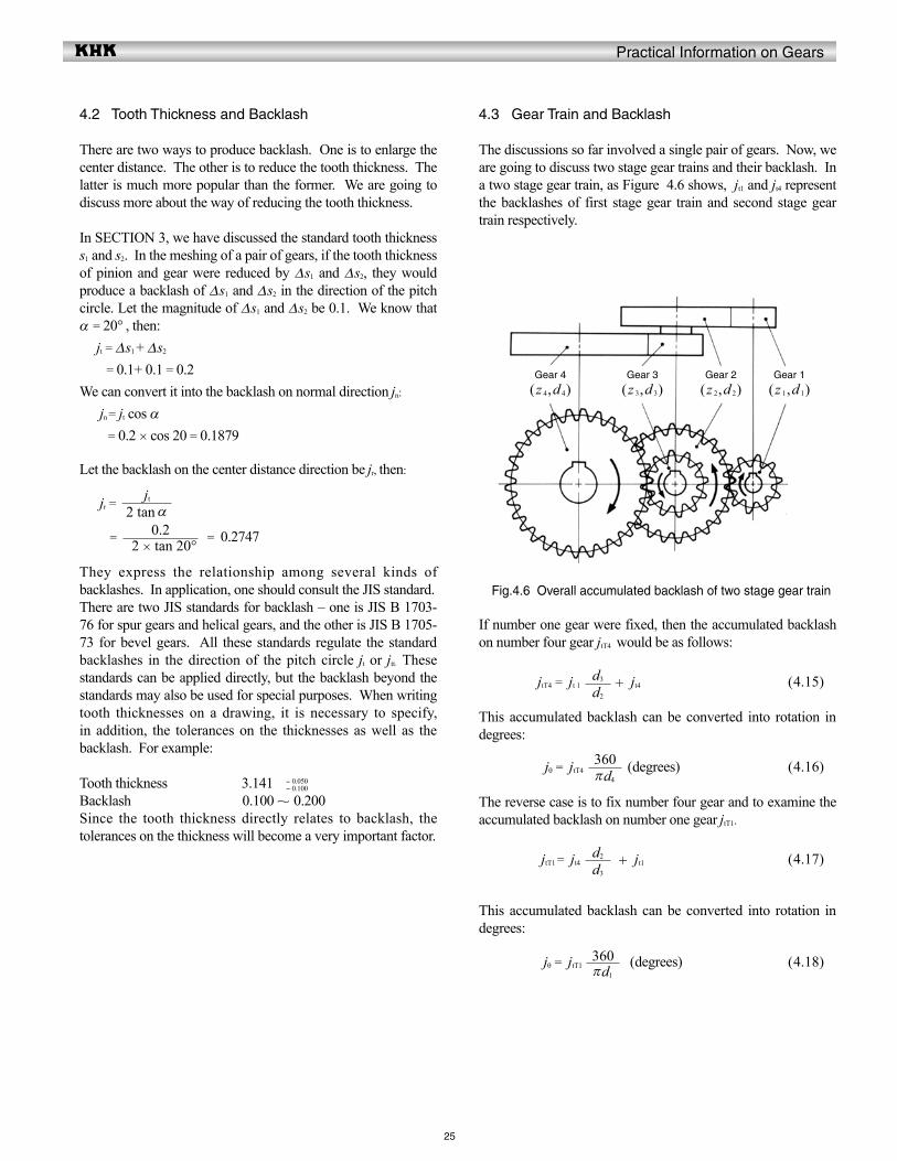
4.3 Gear Train and Backlash
The discussions so far involved a single pair of gears. Now, we are going to discuss two stage gear trains and their backlash. In a two stage gear train, as Figure 4.6 shows, jt1 and jt4 represent the backlashes of first stage gear train and second stage gear train respectively.
If number one gear were fixed, then the accumulated backlash on number four gear jtT4 would be as follows:
jtT4 = jt 1 + jt4 (4.15)
This accumulated backlash can be converted into rotation in degrees:
jθ = jtT4 (degrees) (4.16)
The reverse case is to fix number four gear and to examine the accumulated backlash on number one gear jtT1.
jtT1 = jt4 + jt1 (4.17)
This accumulated backlash can be converted into rotation in degrees:
jθ = jtT1 (degrees) (4.18)
- 0.050- 0.100
2 tan αjt
2 × tan 20°0.2
d2
d3
d3
d2
πd4
360
πd1
360
Fig.4.6 Overall accumulated backlash of two stage gear train
Gear 4
(z 4,d 4)Gear 3
(z 3,d 3)Gear 2
(z 2,d 2)Gear 1
(z 1,d 1)
Practical Information on Gears
26
4.4 Methods of Controlling Backlash
In order to meet special needs, precision gears are used more frequently than ever before. Reducing backlash becomes an important issue. There are two methods of reducing or eliminating backlash – one a static, and the other a dynamic method. The static method concerns means of assembling gears and then making proper adjustments to achieve the desired low backlash. The dynamic method introduces an external force which continually eliminates all backlash regardless of rotational position.
(1) Static Method
This involves adjustment of either the gear's effective tooth thickness or the mesh center distance. These two independent adjustments can be used to produce four possible combinations as shown in Table 4.2.
(A) Case A
By design, center distance and tooth thickness are such that they yield the proper amount of desired minimum backlash. Center distance and tooth thickness size are fixed at correct values and require precision manufacturing.
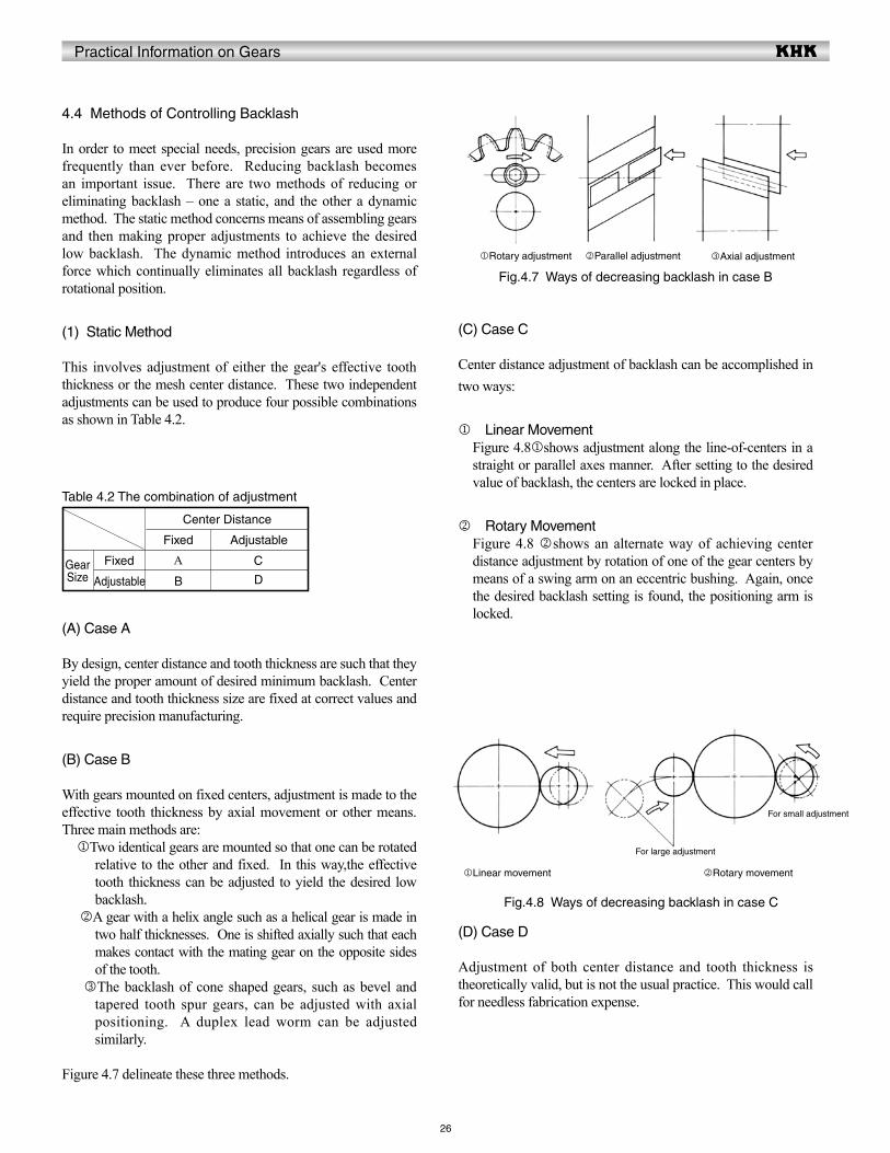
(B) Case B
With gears mounted on fixed centers, adjustment is made to the effective tooth thickness by axial movement or other means. Three main methods are: jTwo identical gears are mounted so that one can be rotated
relative to the other and fixed. In this way,the effective tooth thickness can be adjusted to yield the desired low backlash.
kA gear with a helix angle such as a helical gear is made in two half thicknesses. One is shifted axially such that each makes contact with the mating gear on the opposite sides of the tooth.
lThe backlash of cone shaped gears, such as bevel and tapered tooth spur gears, can be adjusted with axial positioning. A duplex lead worm can be adjusted similarly.
Figure 4.7 delineate these three methods.
(C) Case C
Center distance adjustment of backlash can be accomplished in two ways:
j Linear MovementFigure 4.8jshows adjustment along the line-of-centers in a straight or parallel axes manner. After setting to the desired value of backlash, the centers are locked in place.
k Rotary MovementFigure 4.8 kshows an alternate way of achieving center distance adjustment by rotation of one of the gear centers by means of a swing arm on an eccentric bushing. Again, once the desired backlash setting is found, the positioning arm is locked.
Table 4.2 The combination of adjustment
Gear Size
Center Distance
Fixed
A
B
Adjustable
C
D
Fixed
Adjustable
(D) Case D
Adjustment of both center distance and tooth thickness is theoretically valid, but is not the usual practice. This would call for needless fabrication expense.
Fig.4.7 Ways of decreasing backlash in case B
Fig.4.8 Ways of decreasing backlash in case C
jRotary adjustment kParallel adjustment lAxial adjustment
jLinear movement
For large adjustment
kRotary movement
For small adjustment
Practical Information on Gears
27
(2) Dynamic Methods
Dynamic methods relate to the static techniques. However, they involve a forced adjustment of either the effective tooth thickness or the center distance.
(A) Backlash Removal by Forced Tooth ContactThis is derived from static Case B. Referring to Figure 4.7j, a forcing spring rotates the two gear halves apart. This results in an effective tooth thickness that continually fills the entire tooth space in all mesh positions.
(B) Backlash Removal by Forced Center Distance ClosingThis is derived from static Case C. A spring force is applied to close the center distance; in one case as a linear force along the line-of-centers, and in the other case as a torque applied to the swing arm. In all of these dynamic methods, the applied external force should be known and properly specified. The theoretical relationship of the forces involved is as follows: F > F1 + F2 (4.19)
where: F1 = Transmission Load on Tooth Surface F2 = Friction Force on Tooth Surface
If F < F1 + F2, then it would be impossible to remove backlash. But if F is excessively greater than a proper level, the tooth surfaces would be needlessly loaded and could lead to premature wear and shortened life. Thus, in designing such gears, consideration must be given to not only the needed transmission load, but also the forces acting upon the tooth surfaces caused by the spring load.
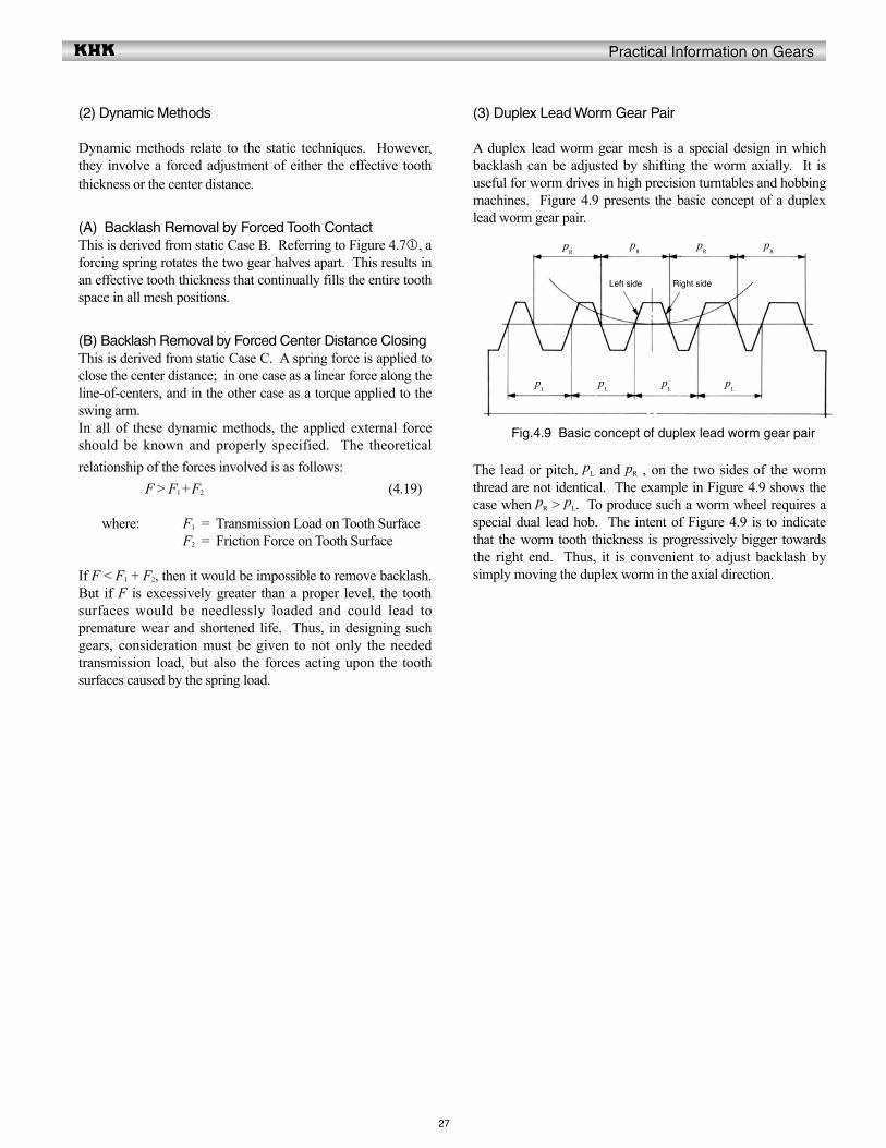
(3) Duplex Lead Worm Gear Pair
A duplex lead worm gear mesh is a special design in which backlash can be adjusted by shifting the worm axially. It is useful for worm drives in high precision turntables and hobbing machines. Figure 4.9 presents the basic concept of a duplex lead worm gear pair.
The lead or pitch, pL and pR , on the two sides of the worm thread are not identical. The example in Figure 4.9 shows the case when pR > pL. To produce such a worm wheel requires a special dual lead hob. The intent of Figure 4.9 is to indicate that the worm tooth thickness is progressively bigger towards the right end. Thus, it is convenient to adjust backlash by simply moving the duplex worm in the axial direction.
Fig.4.9 Basic concept of duplex lead worm gear pair
pR
pR
pR
pR
pL
pL
pL
pL
Right sideLeft side
Practical Information on Gears
28
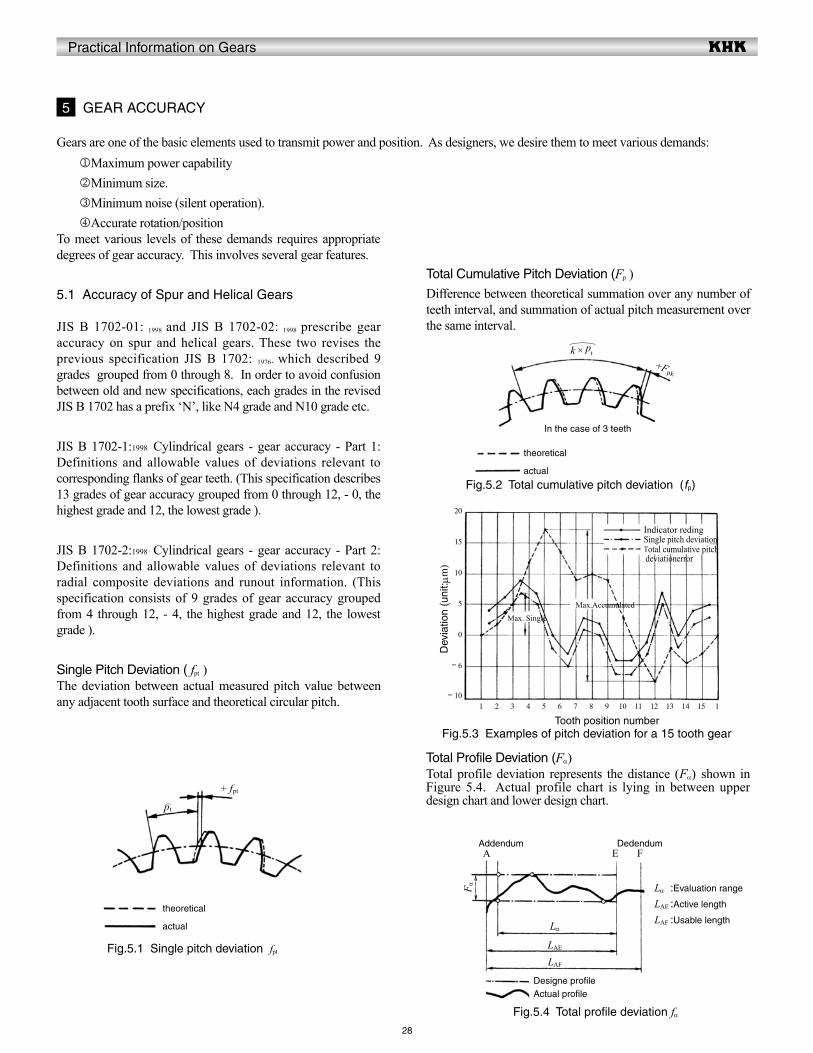
Gears are one of the basic elements used to transmit power and position. As designers, we desire them to meet various demands:
Total Profile Deviation (Fα)Total profile deviation represents the distance (Fα) shown in Figure 5.4. Actual profile chart is lying in between upper design chart and lower design chart.
5 GEAR ACCURACY
jMaximum power capabilitykMinimum size.lMinimum noise (silent operation).mAccurate rotation/position
To meet various levels of these demands requires appropriate degrees of gear accuracy. This involves several gear features.
5.1 Accuracy of Spur and Helical Gears
JIS B 1702-01: 1998 and JIS B 1702-02: 1998 prescribe gear accuracy on spur and helical gears. These two revises the previous specification JIS B 1702: 1976. which described 9 grades grouped from 0 through 8. In order to avoid confusion between old and new specifications, each grades in the revised JIS B 1702 has a prefix ‘N’, like N4 grade and N10 grade etc.
JIS B 1702-1:1998 Cylindrical gears - gear accuracy - Part 1: Definitions and allowable values of deviations relevant to corresponding flanks of gear teeth. (This specification describes 13 grades of gear accuracy grouped from 0 through 12, - 0, the highest grade and 12, the lowest grade ).
JIS B 1702-2:1998 Cylindrical gears - gear accuracy - Part 2: Definitions and allowable values of deviations relevant to radial composite deviations and runout information. (This specification consists of 9 grades of gear accuracy grouped from 4 through 12, - 4, the highest grade and 12, the lowest grade ).
Single Pitch Deviation ( fpt )The deviation between actual measured pitch value between any adjacent tooth surface and theoretical circular pitch.
Fig.5.3 Examples of pitch deviation for a 15 tooth gear
Fig.5.4 Total profile deviation fα
Fig.5.1 Single pitch deviation fpt
theoretical
actual
+ fpt
pt
Fig.5.2 Total cumulative pitch deviation (fp)
theoretical
actual
In the case of 3 teeth
+Fpk
k × pt
Total Cumulative Pitch Deviation (Fp )Difference between theoretical summation over any number of teeth interval, and summation of actual pitch measurement over the same interval.
20
15
10
5
0
- 6
- 101 2 3 4 5 6 7 8 9 10 11 12 13 14 15 1
Indicator redingSingle pitch deviationTotal cumulative pitch deviationerror
Max. Single
Max.Accumulated
Dev
iatio
n (u
nit: m
m)
Tooth position number
Designe profileActual profile
Addendum DedendumA E F
Lα :Evaluation range
LAE :Active length
LAF :Usable length
F α
Lα
LAE
LAF
Practical Information on Gears
29
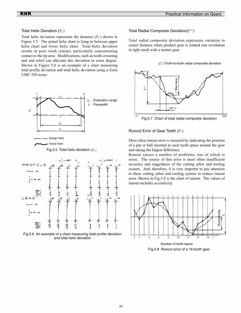
Total Helix Deviation (Fβ )Total helix deviation represents the distance (Fβ ) shown in Figure 5.5. The actual helix chart is lying in between upper helix chart and lower helix chart. Total helix deviation results in poor tooth contact, particularly concentrating contact to the tip area. Modifications, such as tooth crowning and end relief can alleviate this deviation to some degree. Shown in Figure 5.6 is an example of a chart measuring total profile deviation and total helix deviation using a Zeiss UMC 550 tester.
Total Radial Composite Deviation(Fi'' )
Total radial composite deviation represents variation in center distance when product gear is rotated one revolution in tight mesh with a master gear.
Runout Error of Gear Teeth (Fr )
Most often runout error is mesured by indicating the position of a pin or ball inserted in each tooth space around the gear and taking the largest difference.Runout causes a number of problems, one of which is noise. The source of this error is most often insufficient accuracy and ruggedness of the cutting arbor and tooling system. And, therefore, it is very importnt to pay attention to these cutting arbor and tooling system to reduce runout error. Shown in Fig.5.8 is the chart of runout. The values of runout includes eccentricity.
Fig.5.5 Total helix deviation (Fβ )
Fig.5.6 An example of a chart measuring total profile deviation and total helix deviation
Fig.5.7 Chart of total radial composite deviation
Fig.5.8 Runout error of a 16-tooth gear
Design helix
Actual helix
Lβ : Evaluation range b : Facewidth
F β
Lβ
b
-
+
(fi'' ):Tooth-to-tooth radial composite deviation
F i''
f i' M
ax.v
alue
0° 360°
360° /z
1 2 4 6 8 10 12 14 16 1
F rE
ccen
tric
ity
Number of tooth space
Practical Information on Gears
Single pitch error, k
30
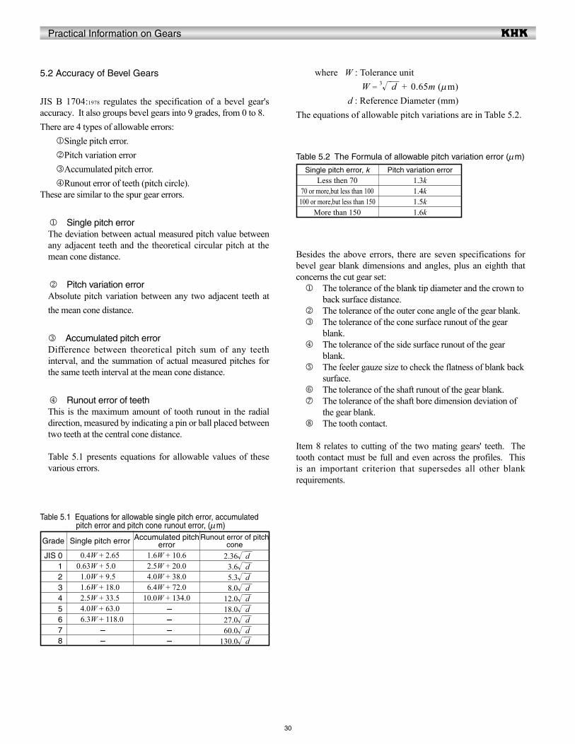
5.2 Accuracy of Bevel Gears
JIS B 1704:1978 regulates the specification of a bevel gear's accuracy. It also groups bevel gears into 9 grades, from 0 to 8.There are 4 types of allowable errors:jSingle pitch error.kPitch variation errorlAccumulated pitch error.mRunout error of teeth (pitch circle).
These are similar to the spur gear errors.
j Single pitch error The deviation between actual measured pitch value between any adjacent teeth and the theoretical circular pitch at the mean cone distance.
k Pitch variation error Absolute pitch variation between any two adjacent teeth at the mean cone distance.
l Accumulated pitch error Difference between theoretical pitch sum of any teeth interval, and the summation of actual measured pitches for the same teeth interval at the mean cone distance.
m Runout error of teeth This is the maximum amount of tooth runout in the radial direction, measured by indicating a pin or ball placed between two teeth at the central cone distance.
Table 5.1 presents equations for allowable values of these various errors.
where W : Tolerance unit W = 3 d + 0.65m (mm) d : Reference Diameter (mm)The equations of allowable pitch variations are in Table 5.2.
Table 5.1 Equations for allowable single pitch error, accumulated pitch error and pitch cone runout error, (mm)
Grade
JIS 0JIS 1JIS 2JIS 3JIS 4JIS 5JIS 6JIS 7JIS 8
Single pitch error
00.4W + 2.6500.63W + 5.00001.0W + 9.50001.6W + 18.0002.5W + 33.5004.0W + 63.0006.3W + 118.0
- -
Accumulated pitch error
01.6W + 10.6002.5W + 20.0004.0W + 38.0006.4W + 72.0010.0W + 134.0
- - - -
Runout error of pitch cone
02.36 d003.6 d005.3 d008.0 d012.0 d018.0 d027.0 d060.0 d130.0 d
Table 5.2 The Formula of allowable pitch variation error (mm)
Less then 7070 or more,but less than 100
100 or more,but less than 150More than 150
Pitch variation error1.3k1.4k1.5k1.6k
Besides the above errors, there are seven specifications for bevel gear blank dimensions and angles, plus an eighth that concerns the cut gear set: j The tolerance of the blank tip diameter and the crown to
back surface distance. k The tolerance of the outer cone angle of the gear blank. l The tolerance of the cone surface runout of the gear
blank. m The tolerance of the side surface runout of the gear
blank. n The feeler gauze size to check the flatness of blank back
surface. o The tolerance of the shaft runout of the gear blank. p The tolerance of the shaft bore dimension deviation of
the gear blank. q The tooth contact.
Item 8 relates to cutting of the two mating gears' teeth. The tooth contact must be full and even across the profiles. This is an important criterion that supersedes all other blank requirements.

Practical Information on Gears
31
5.3 Running (Dynamic) Gear Testing
An alternate simple means of testing the general accuracy of a gear is to rotate it with a mate, preferably of known high quality, and measure characteristics during rotation. This kind of tester can be either single contact (fixed center distance method) or dual (variable center distance method). This refers to action on one side or simultaneously on both sides of the tooth. This is also commonly referred to as single and double flank testing. Because of simplicity, dual contact testing is more popular than single contact.
(1) Dual Contact (Double Flank) Testing
In this technique, the gear is forced meshed with a master gear such that there is intimate tooth contact on both sides and, therefore, no backlash. The contact is forced by a loading spring. As the gears rotate, there is variation of center distance due to various errors, most notably runout. This variation is measured and is a criterion of gear quality. A full rotation presents the total gear error, while rotation through one pitch is a tooth-to-tooth error. Figure 5.9 presents a typical plot for such a test.
where W : Tolerance unit W = 3√ d + 0.65m (μm) d : Reference diameter (mm) m : Module (mm)
(2) Single Contact Testing
In this test, the gear is mated with a master gear on a fixed center distance and set in such a way that only one tooth side makes contact. The gears are rotated through this single flank contact action, and the angular transmission error of the driven gear is measured. This is a tedious testing method and is seldom used except for inspection of the very highest precision gears.
Allowable errors per JGMA 116-01 are presented in Table 5.3.
Grade Tooth-to-tooth composite error Total composite error
Table 5.3 Allowable values of running errors, (mm)
Extra fine (0) 1.12m + 3.5501.6m + 5.002.24m + 7.103.15m + 10.004.5m + 14.006.3m + 20.009.0m + 28.012.5m + 40.018.0m + 56.0
( ( 1.4W + 4.0) + 0.5 ( 1.12m + 3.55) ((12.0W + 05.6) + 0.5 ((1.6 m + 05.0) ((12.8W + 08.0) + 0.5 ((2.24m + 07.1) ((14.0W + 11.2) + 0.5 ((3.15m + 10.0) ((15.6W + 16.0) + 0.5 ((04.5m + 14.0) ((18.0W + 22.4) + 0.5 ((06.3m + 20.0) ((11.2W + 31.5) + 0.5 ((09.0m + 28.0) ((22.4W + 63.0) + 0.5 ((12.5m + 40.0) ( 45.0W + 125.0) + 0.5 ((18.0m + 56.0)
1
2
3
4
5
6
7
8
Fig.5.9 Example of dual contact running testing report
One pitch running error
Total running error
One turn
Practical Information on Gears
Level
32
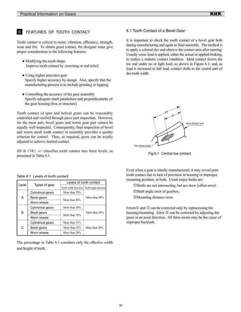
6.1 Tooth Contact of a Bevel Gear
It is important to check the tooth contact of a bevel gear both during manufacturing and again in final assembly. The method is to apply a colored dye and observe the contact area after running. Usually some load is applied, either the actual or applied braking, to realize a realistic contact condition. Ideal contact favors the toe end under no or light load, as shown in Figure 6.1; and, as load is increased to full load, contact shifts to the central part of the tooth width.
6 FEATURES OF TOOTH CONTACT
Tooth contact is critical to noise, vibration, efficiency, strength, wear and life. To obtain good contact, the designer must give proper consideration to the following features:
● Modifying the tooth shape Improve tooth contact by crowning or end relief.
● Using higher precision gear Specify higher accuracy by design. Also, specify that the manufacturing process is to include grinding or lapping.
● Controlling the accuracy of the gear assembly Specify adequate shaft parallelism and perpendicularity of the gear housing (box or structure)
Tooth contact of spur and helical gears can be reasonably controlled and verified through piece part inspection. However, for the most part, bevel gears and worm gear pair cannot be equally well inspected. Consequently, final inspection of bevel and worm mesh tooth contact in assembly provides a quality criterion for control. Then, as required, gears can be axially adjusted to achieve desired contact.
JIS B 1741: 1977 classifies tooth contact into three levels, as presented in Table 6.1.
Table 6.1 Levels of tooth contact
A
B
C
Types of gear
Cylindrical gears
Bevel gears
Worm wheels
Cylindrical gears
Bevel gears
Worm wheels
Cylindrical gears
Bevel gears
Worm wheels
Levels of tooth contact
Tooth width direction
More than 70%
More than 50%
More than 50%
More than 35%
More than 35%More than 25%More than 20%
Tooth height direction
More than 40%
More than 30%
More than 20%
The percentage in Table 6.1 considers only the effective width and height of teeth.
Even when a gear is ideally manufactured, it may reveal poor tooth contact due to lack of precision in housing or improper mounting position, or both. Usual major faults are:jShafts are not intersecting, but are skew (offset error)kShaft angle error of gearbox.lMounting distance error.
Errorsj and k can be corrected only by reprocessing the housing/mounting. Error l can be corrected by adjusting the gears in an axial direction. All three errors may be the cause of improper backlash.
Fig.6.1 Central toe contact
Toe (Inner) end
Heel (Outer) end
10060
Practical Information on Gears
33
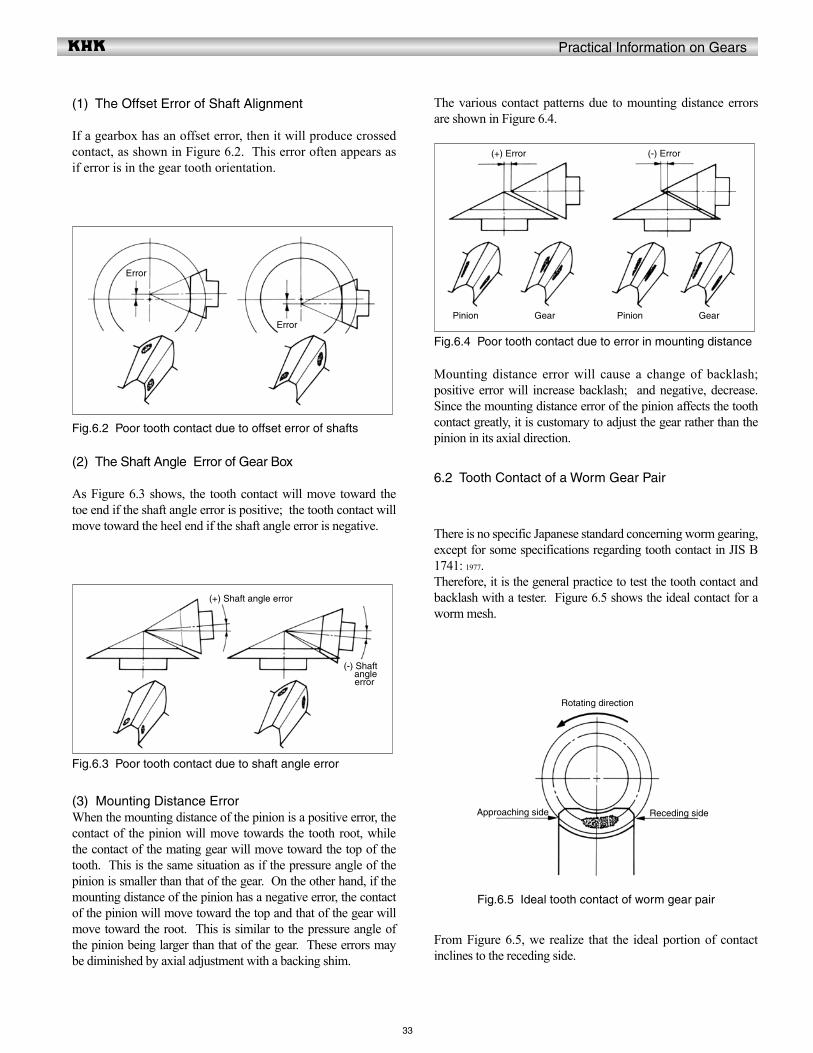
(1) The Offset Error of Shaft Alignment
If a gearbox has an offset error, then it will produce crossed contact, as shown in Figure 6.2. This error often appears as if error is in the gear tooth orientation.
The various contact patterns due to mounting distance errors are shown in Figure 6.4.
(2) The Shaft Angle Error of Gear Box
As Figure 6.3 shows, the tooth contact will move toward the toe end if the shaft angle error is positive; the tooth contact will move toward the heel end if the shaft angle error is negative.
(3) Mounting Distance ErrorWhen the mounting distance of the pinion is a positive error, the contact of the pinion will move towards the tooth root, while the contact of the mating gear will move toward the top of the tooth. This is the same situation as if the pressure angle of the pinion is smaller than that of the gear. On the other hand, if the mounting distance of the pinion has a negative error, the contact of the pinion will move toward the top and that of the gear will move toward the root. This is similar to the pressure angle of the pinion being larger than that of the gear. These errors may be diminished by axial adjustment with a backing shim.
Mounting distance error will cause a change of backlash; positive error will increase backlash; and negative, decrease. Since the mounting distance error of the pinion affects the tooth contact greatly, it is customary to adjust the gear rather than the pinion in its axial direction.
6.2 Tooth Contact of a Worm Gear Pair
There is no specific Japanese standard concerning worm gearing, except for some specifications regarding tooth contact in JIS B 1741: 1977.Therefore, it is the general practice to test the tooth contact and backlash with a tester. Figure 6.5 shows the ideal contact for a worm mesh.
From Figure 6.5, we realize that the ideal portion of contact inclines to the receding side.
Fig.6.2 Poor tooth contact due to offset error of shafts
Fig.6.3 Poor tooth contact due to shaft angle error
Fig.6.4 Poor tooth contact due to error in mounting distance
Fig.6.5 Ideal tooth contact of worm gear pair
Error
Error
(+) Shaft angle error
(-) Shaft angle error
(+) Error (-) Error
Pinion Gear Pinion Gear
Rotating direction
Approaching side Receding side
Practical Information on Gears
34
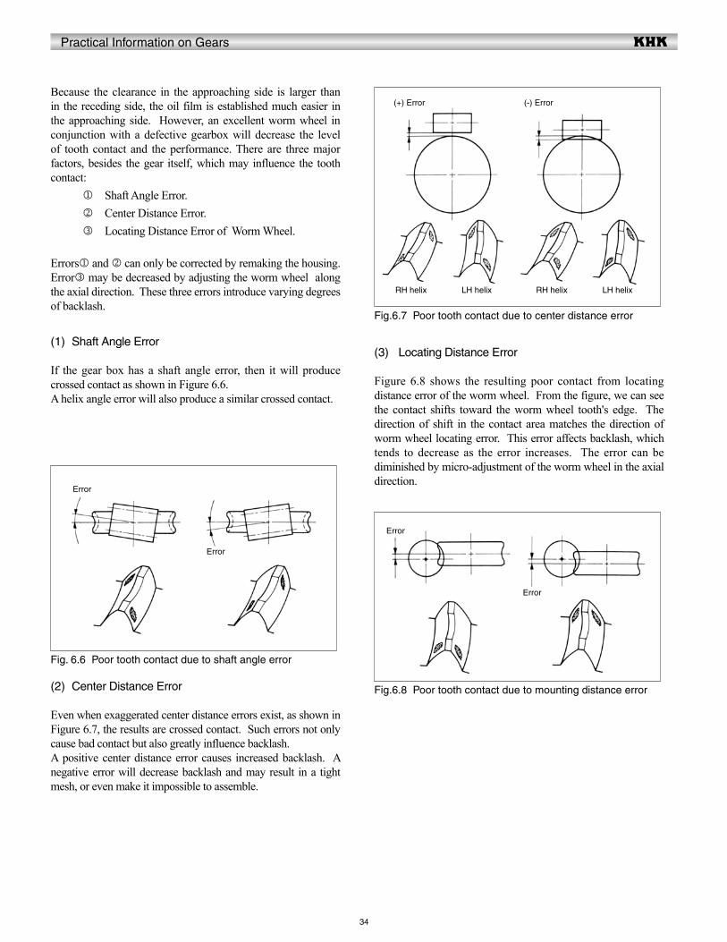
Because the clearance in the approaching side is larger than in the receding side, the oil film is established much easier in the approaching side. However, an excellent worm wheel in conjunction with a defective gearbox will decrease the level of tooth contact and the performance. There are three major factors, besides the gear itself, which may influence the tooth contact:
j Shaft Angle Error.k Center Distance Error.l Locating Distance Error of Worm Wheel.
Errorsj and k can only be corrected by remaking the housing. Errorl may be decreased by adjusting the worm wheel along the axial direction. These three errors introduce varying degrees of backlash.
(1) Shaft Angle Error
If the gear box has a shaft angle error, then it will produce crossed contact as shown in Figure 6.6.A helix angle error will also produce a similar crossed contact.
(3) Locating Distance Error
Figure 6.8 shows the resulting poor contact from locating distance error of the worm wheel. From the figure, we can see the contact shifts toward the worm wheel tooth's edge. The direction of shift in the contact area matches the direction of worm wheel locating error. This error affects backlash, which tends to decrease as the error increases. The error can be diminished by micro-adjustment of the worm wheel in the axial direction.
(2) Center Distance Error
Even when exaggerated center distance errors exist, as shown in Figure 6.7, the results are crossed contact. Such errors not only cause bad contact but also greatly influence backlash. A positive center distance error causes increased backlash. A negative error will decrease backlash and may result in a tight mesh, or even make it impossible to assemble.
Fig. 6.6 Poor tooth contact due to shaft angle error
Fig.6.7 Poor tooth contact due to center distance error
Fig.6.8 Poor tooth contact due to mounting distance error
Error
(+) Error
Error
Error
Error
(-) Error
RH helix LH helix RH helix LH helix
Practical Information on Gears
The purpose of lubricating gears is as follows: 1. Promote sliding between teeth to reduce the coefficient of friction m . 2. Limit the temperature rise caused by rolling and sliding friction.
To avoid difficulties such as tooth wear and premature failure, the correct lubricant must be chosen.
7.1 Methods of Lubrication
There are three gear lubrication methods in general use: (1) Grease lubrication. (2) Splash lubrication (oil bath method). (3) Forced oil circulation lubrication.
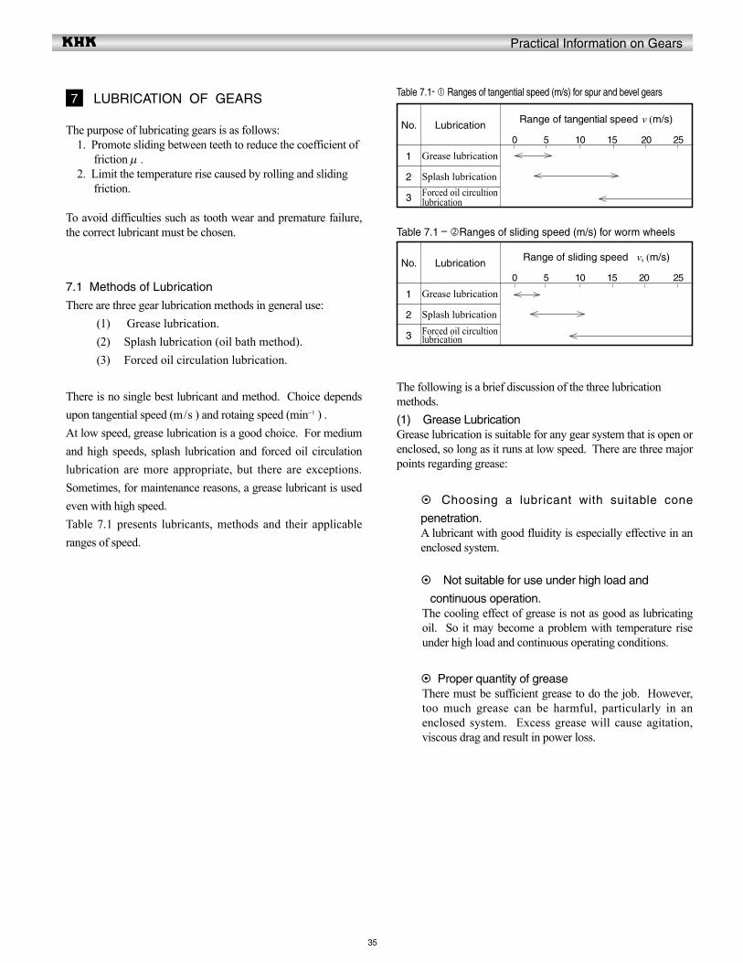
There is no single best lubricant and method. Choice depends upon tangential speed (m/s ) and rotaing speed (min-1 ) .At low speed, grease lubrication is a good choice. For medium and high speeds, splash lubrication and forced oil circulation lubrication are more appropriate, but there are exceptions. Sometimes, for maintenance reasons, a grease lubricant is used even with high speed. Table 7.1 presents lubricants, methods and their applicable ranges of speed.
35
The following is a brief discussion of the three lubrication methods.(1) Grease LubricationGrease lubrication is suitable for any gear system that is open or enclosed, so long as it runs at low speed. There are three major points regarding grease:
Choosing a lubricant with suitable cone
penetration.A lubricant with good fluidity is especially effective in an enclosed system.
Not suitable for use under high load and
continuous operation.The cooling effect of grease is not as good as lubricating oil. So it may become a problem with temperature rise under high load and continuous operating conditions.
Proper quantity of greaseThere must be sufficient grease to do the job. However, too much grease can be harmful, particularly in an enclosed system. Excess grease will cause agitation, viscous drag and result in power loss.
7 LUBRICATION OF GEARS Table 7.1- Ranges of tangential speed (m/s) for spur and bevel gears
No.
1
2
3
Lubrication
Grease lubrication
Splash lubricationForced oil circultion lubrication
Range of tangential speed v (m/s)
0 5 10 15 20 25
Table 7.1 – Ranges of sliding speed (m/s) for worm wheels
No.
1
2
3
Lubrication
Grease lubrication
Splash lubricationForced oil circultion lubrication
Range of sliding speed vs (m/s)
0 5 10 15 20 25
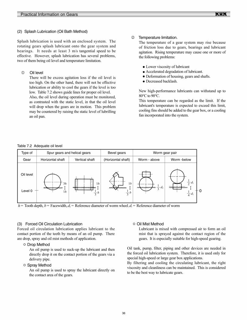
Practical Information on Gears
36
(2) Splash Lubrication (Oil Bath Method)
Splash lubrication is used with an enclosed system. The rotating gears splash lubricant onto the gear system and bearings. It needs at least 3 m/s tangential speed to be effective. However, splash lubrication has several problems, two of them being oil level and temperature limitation.
j Oil levelThere will be excess agitation loss if the oil level is too high. On the other hand, there will not be effective lubrication or ability to cool the gears if the level is too low. Table 7.2 shows guide lines for proper oil level.Also, the oil level during operation must be monitored, as contrasted with the static level, in that the oil level will drop when the gears are in motion. This problem may be countered by raising the static level of lubrilling an oil pan.
k Temperature limitation.The temperature of a gear system may rise because of friction loss due to gears, bearings and lubricant agitation. Rising temperature may cause one or more of the following problems:
Lower viscosity of lubricant Accelerated degradation of lubricant. Deformation of housing, gears and shafts. Decreased backlash.
New high-performance lubricants can withstand up to 80°C to 90°C.This temperature can be regarded as the limit. If the lubricant's temperature is expected to exceed this limit, cooling fins should be added to the gear box, or a cooling fan incorporated into the system.
Table 7.2 Adequate oil level
Type of Spur gears and helical gears Bevel gears Worm gear pair
Gear
Oil level
Level 0
Horizontal shaft Vertical shaft (Horizontal shaft) Worm - above Worm -below
h = Tooth depth, b = Facewidth, d2 = Reference diameter of worm wheel, d1 = Reference diameter of worm
(3) Forced Oil Circulation LubricationForced oil circulation lubrication applies lubricant to the contact portion of the teeth by means of an oil pump. There are drop, spray and oil mist methods of application. O Drop Method
An oil pump is used to suck-up the lubricant and then directly drop it on the contact portion of the gears via a delivery pipe.
O Spray MethodAn oil pump is used to spray the lubricant directly on the contact area of the gears.
O Oil Mist MethodLubricant is mixed with compressed air to form an oil mist that is sprayed against the contact region of the gears. It is especially suitable for high-speed gearing.
Oil tank, pump, filter, piping and other devices are needed in the forced oil lubrication system. Therefore, it is used only for special high-speed or large gear box applications. By filtering and cooling the circulating lubricant, the right viscosity and cleanliness can be maintained. This is considered to be the best way to lubricate gears.
0
3h↑↓1h
1h↑↓ h
1b↑↓ b
↑↓
d131
31
d231 2
1
41
d1
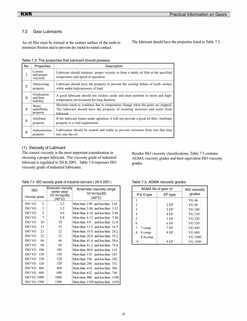
Practical Information on Gears
37
7.2 Gear Lubricants
An oil film must be formed at the contact surface of the teeth to minimize friction and to prevent dry metal-to-metal contact.
The lubricant should have the properties listed in Table 7.3.
Table 7.3 The properties that lubricant should possess
No.
1
2
3
4
5
6
Properties
Correct and proper viscosity
Antiscoring property
Oxidization and heat stabilityWater antiaffinity property
Antifoam property
Anticorrosion property
Description
Lubricant should maintain proper vicosity to form a stable oil film at the specified temperature and speed of operation.
Lubricant should have the property to prevent the scoring failure of tooth surface while under high-pressure of load.
A good lubricant should not oxidize easily and must perform in moist and high-temperature environment for long duration.Moisture tends to condense due to temperature change when the gears are stopped. The lubricant should have the property of isolating moisture and water from lubricantIf the lubricant foams under agitation, it will not provide a good oil film. Antifoam property is a vital requirement.
Lubrication should be neutral and stable to prevent corrosion from rust that may mix into the oil.
(1) Viscosity of LubricantThe correct viscosity is the most important consideration in choosing a proper lubricant. The viscosity grade of industrial lubricant is regulated in JIS K 2001. Table 7.4 expresses ISO viscosity grade of industrial lubricants.
Besides ISO viscosity classifications, Table 7.5 contains AGMA viscosity grades and their equivalent ISO viscosity grades.
Table 7.4 ISO viscosity grade of industrial lubricant ( JIS K 2001 ) Table 7.5 AGMA viscosity grades
ISO
Viscosity grade
AGMA No.of gear oil
R & O type
ISO VG 1502 ISO VG 1503ISO VG 1505ISO VG 1507ISO VG 1510ISO VG 1515ISO VG 1522ISO VG 1532ISO VG 1546ISO VG 1568ISO VG 1100ISO VG 1150ISO VG 1220ISO VG 1320ISO VG 1460ISO VG 1680ISO VG 1000ISO VG 1500
1 8 Acomp2 8 Acomp3 8 Acomp4 8 Acomp5 8 Acomp6 8 Acomp7 7 compA8 8 compA1 8 Acomp9 8 Acomp
Kinematic viscosity center value
10-6m2/s(cSt)(40°C)
EP type
1502.21503.21504.61506.81510.01515.01522.21532.21546.21568.21100.21150.21220.21320.21460.21680.21000.21500.2
2 Ep2 EP3 EP4 EP5 EP6 EP7 EP8 EP2 Ep9 EP
Kinematic viscosity range10-6m2/s(cSt)
(40°C)
ISO viscosity grades
More than 1.98 and less than 2.42 More than 2.88 and less than 3.52 More than 4.14 and less than 5.06 More than 6.12 and less than 7.48 More than 9.0 and less than 11.00More than 13.5 and less than 16.5More than 19.8 and less than 24.2More than 28.8 and less than 35.2More than 41.4 and less than 50.6More than 61.2 and less than 74.8More than 90.0 and less than 110More than 135 and less than 165More than 198 and less than 242More than 288. and less than 352More than 414 and less than 506.More than 612. and less than 748More than 900 and less than 1100.More than 1350 and less than 1650
VG 4600VG 6800VG 1000VG 1500VG 2200VG 3200VG 4600VG 6800VG 1000VG 1500
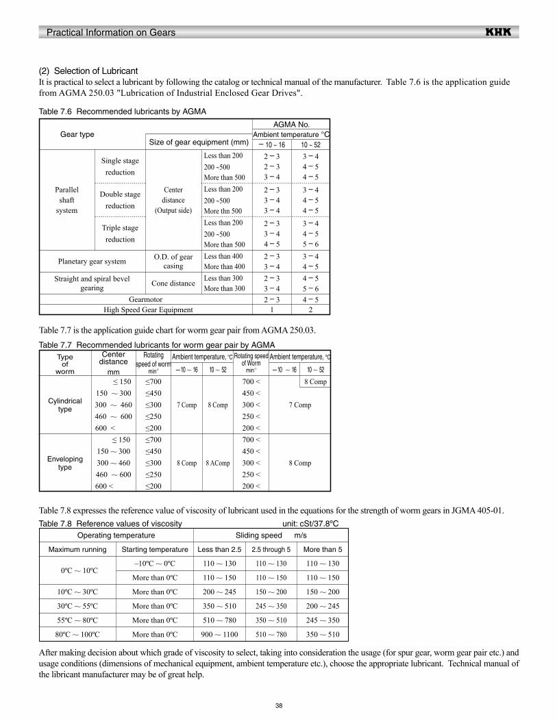
Practical Information on Gears
38
(2) Selection of LubricantIt is practical to select a lubricant by following the catalog or technical manual of the manufacturer. Table 7.6 is the application guide from AGMA 250.03 "Lubrication of Industrial Enclosed Gear Drives".
Table 7.7 is the application guide chart for worm gear pair from AGMA 250.03.
Table 7.6 Recommended lubricants by AGMA
Gear typeAGMA No.
Ambient temperature °C– 10 ~ 16
2 – 32 – 33 – 4
2 – 33 – 43 – 4
2 – 33 – 44 – 52 – 33 – 42 – 33 – 42 – 3
1
10 ~ 52
3 – 44 – 54 – 5
3 – 44 – 54 – 5
3 – 44 – 55 – 63 – 44 – 54 – 55 – 64 – 5
2
Size of gear equipment (mm)
Less than 200200 ~500More than 500
Centerdistance
(Output side)
Double stage reduction
Single stage reduction
Triple stage reduction
Planetary gear system O.D. of gear casing
Cone distance
Less than 400More than 400Less than 300More than 300
Straight and spiral bevel gearing
GearmotorHigh Speed Gear Equipment
Less than 200200 ~500More thn 500Less than 200200 ~500More than 500
Parallelshaft
system
Table 7.7 Recommended lubricants for worm gear pair by AGMAType
ofworm
Cylindricaltype
Envelopingtype
Center distance
mm1 ≤ 150150 ~ 300300 ~ 460460 ~ 600
600 <150150 ≤ 150150 ~ 300300 ~ 460460 ~ 600
600 <150
Rotating speed of worm
min-1
≤700≤450≤300≤250≤200≤700≤450≤300≤250≤200
Rotating speed of Worm
min-1
700 <450 <300 <250 <200 <700 <450 <300 <250 <200 <
Ambient temperature, ºC Ambient temperature, ºC
– 10 ~ 16
7 Comp
8 Comp
– 10 ~ 16
7 Comp
8 Comp
10 ~ 52
8 Comp
8 AComp
10 ~ 52
8 Comp
Table 7.8 expresses the reference value of viscosity of lubricant used in the equations for the strength of worm gears in JGMA 405-01.Table 7.8 Reference values of viscosity unit: cSt/37.8ºC
Operating temperature
Maximum running
10ºC ~ 10ºC
10ºC ~ 30ºC
30ºC ~ 55ºC
55ºC ~ 80ºC
80ºC ~ 100ºC
Starting temperature
–10ºC ~ 0ºC
More than 0ºC
More than 0ºC
More than 0ºC
More than 0ºC
More than 0ºC
Less than 2.5
110 ~ 130
110 ~ 150
200 ~ 245
350 ~ 510
510 ~ 780
900 ~ 1100
2.5 through 5
110 ~ 130
110 ~ 150
150 ~ 200
245 ~ 350
350 ~ 510
510 ~ 780
More than 5
110 ~ 130
110 ~ 150
150 ~ 200
200 ~ 245
245 ~ 350
350 ~ 510
Sliding speed m/s
After making decision about which grade of viscosity to select, taking into consideration the usage (for spur gear, worm gear pair etc.) and usage conditions (dimensions of mechanical equipment, ambient temperature etc.), choose the appropriate lubricant. Technical manual of the libricant manufacturer may be of great help.
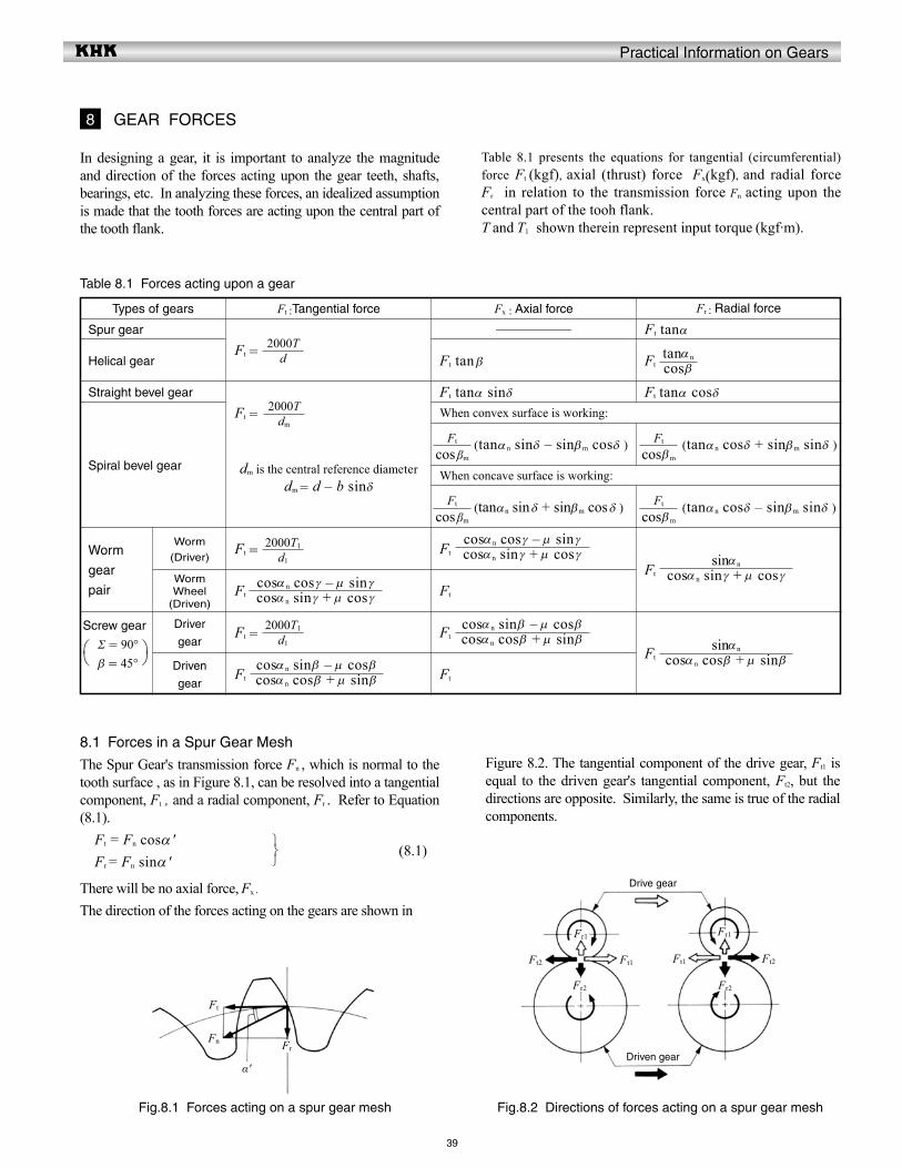
Practical Information on Gears
39
Table 8.1 presents the equations for tangential (circumferential) force Ft (kgf), axial (thrust) force Fx(kgf), and radial force Fr in relation to the transmission force Fn acting upon the central part of the tooh flank.T and T1 shown therein represent input torque (kgf·m).
In designing a gear, it is important to analyze the magnitude and direction of the forces acting upon the gear teeth, shafts, bearings, etc. In analyzing these forces, an idealized assumption is made that the tooth forces are acting upon the central part of the tooth flank.
8 GEAR FORCES
Table 8.1 Forces acting upon a gear
Types of gears
Spur gear
Straight bevel gear
Helical gear
Spiral bevel gear
Worm
gear
pair
Screw gear
Σ = 90° β = 45°
Worm
(Driver)
Worm Wheel
(Driven)
Driver
gear
Driven
gear
Ft :Tangential force
Ft =
Ft =
dm is the central reference diameterdm = d – b sinδ
Ft =
Ft
Ft =
Ft
Fx : Axial force
——————
Ft tanα sinδ
(tanα n sinδ – sinβm cosδ )
(tanαn sin δ + sinβm cos δ )
Ft
Ft
Ft
Ft
(tanα n cosδ + sinβm sinδ )
(tanα n cosδ – sinβm sinδ )
Ft
Ft
Ft tan β
Fr : Radial force
Ft tanα
Ft tanα cosδ
When convex surface is working:
When concave surface is working:
Ft
8.1 Forces in a Spur Gear Mesh
The Spur Gear's transmission force Fn , which is normal to the tooth surface , as in Figure 8.1, can be resolved into a tangential component, Ft , and a radial component, Fr . Refer to Equation (8.1). Ft = Fn cosα ' Fr = Fn sinα '
There will be no axial force, Fx .
The direction of the forces acting on the gears are shown in
(8.1)
Table 7.8 expresses the reference value of viscosity of lubricant used in the equations for the strength of worm gears in JGMA 405-01.
d2000T
dm
2000T
d1
2000T1
d1
2000T1
cosα n sin γ + m cos γcosα n cos γ – m sin γ
cosα n cos β + m sin βcosα n sin β – m cos β
cosα n cos β + m sin βcosα n sin β – m cos β
cosα n sin γ + m cos γcosα n cos γ – m sin γ
cos βm
Ft
cos βm
Ft
cos βm
Ft
cos βm
Ft
cos βtanα n
cosα n sin γ + m cos γsinαn
cosα n cos β + m sin βsinαn
Fig.8.1 Forces acting on a spur gear mesh Fig.8.2 Directions of forces acting on a spur gear mesh
Ft
Fn Fr
α'
Ft2 Ft1 Ft1 Ft2
Drive gear
Driven gear
Fr1 Fr1
Fr2 Fr2
Figure 8.2. The tangential component of the drive gear, Ft1 is equal to the driven gear's tangential component, Ft2, but the directions are opposite. Similarly, the same is true of the radial components.
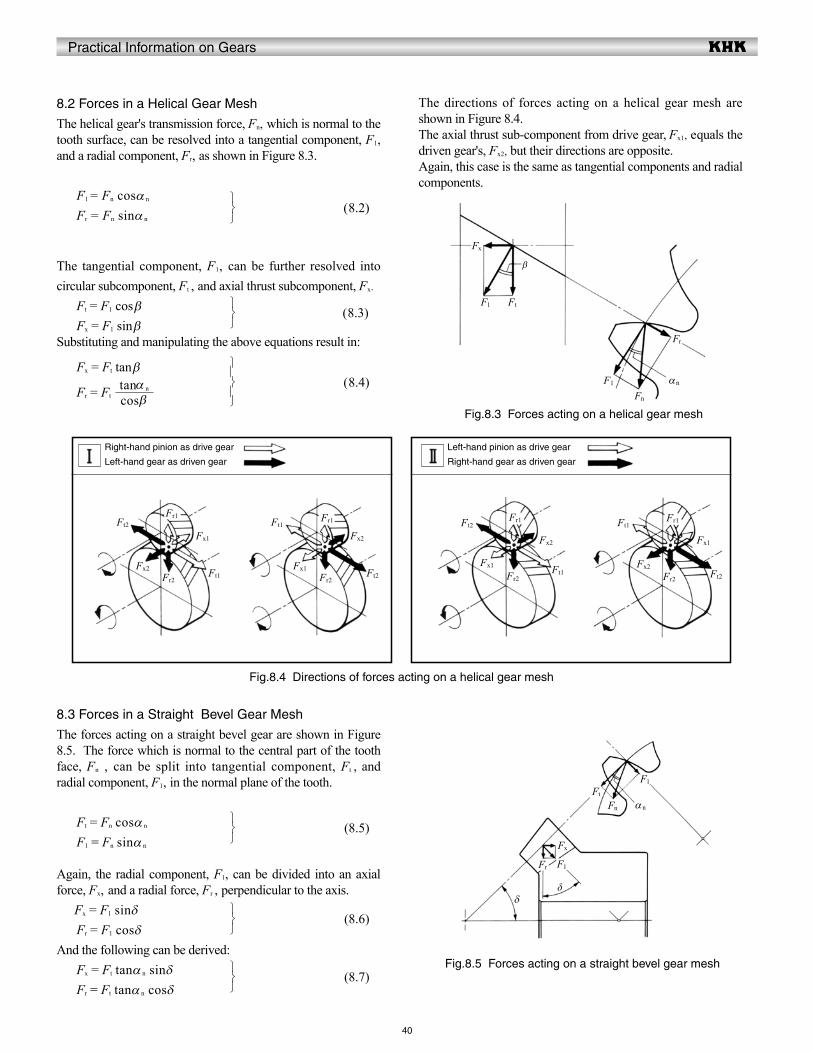
Practical Information on Gears
40
8.2 Forces in a Helical Gear Mesh
The helical gear's transmission force, Fn, which is normal to the tooth surface, can be resolved into a tangential component, F1, and a radial component, Fr, as shown in Figure 8.3.
F1 = Fn cosα n
Fr = Fn sinα n
The tangential component, F1, can be further resolved into circular subcomponent, Ft , and axial thrust subcomponent, Fx.
Ft = F1 cos β Fx = F1 sin βSubstituting and manipulating the above equations result in:
Fx = Ft tan β
Fr = Ft
The directions of forces acting on a helical gear mesh are shown in Figure 8.4.The axial thrust sub-component from drive gear, Fx1, equals the driven gear's, Fx2, but their directions are opposite.Again, this case is the same as tangential components and radial components.
(8.2)
(8.3)
(8.4)
8.3 Forces in a Straight Bevel Gear Mesh
The forces acting on a straight bevel gear are shown in Figure 8.5. The force which is normal to the central part of the tooth face, Fn , can be split into tangential component, Ft , and radial component, F1, in the normal plane of the tooth.
Ft = Fn cosα n
F1 = Fn sinα n
Again, the radial component, F1, can be divided into an axial force, Fx, and a radial force, Fr , perpendicular to the axis. Fx = F1 sinδ Fr = F1 cosδAnd the following can be derived: Fx = Ft tanα n sinδ Fr = Ft tanα n cosδ
(8.5)
(8.6)
(8.7)
cos βtanα n
Fig.8.3 Forces acting on a helical gear mesh
Fig.8.4 Directions of forces acting on a helical gear mesh
Fig.8.5 Forces acting on a straight bevel gear mesh
Ft2
Right-hand pinion as drive gear
Left-hand gear as driven gear
Left-hand pinion as drive gear
Right-hand gear as driven gear
Ft1
Fx1
Fr1
Fx2Fr2
Ft1
Ft2
Fx2
Fr1
Fx1Fr2
Ft2
Ft1
Fx2
Fr1
Fx1
Fr2
Ft1
Ft2
Fx1
Fr1
Fx2
Fr2
Fx
F1 Ft
β
F1
Fn
Fr
αn
Fn αn
Ft
Fx
F1Fr
F1
δδ
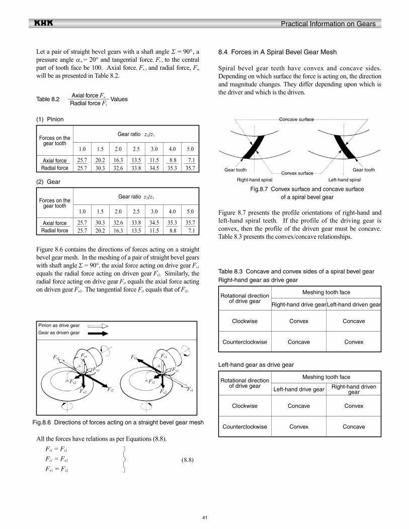
Practical Information on Gears
41
Let a pair of straight bevel gears with a shaft angle Σ = 90° , a pressure angle αn = 20° and tangential force, Ft , to the central part of tooth face be 100. Axial force, Fx , and radial force, Fr, will be as presented in Table 8.2.
Table 8.2 Values
8.4 Forces in A Spiral Bevel Gear Mesh
Spiral bevel gear teeth have convex and concave sides. Depending on which surface the force is acting on, the direction and magnitude changes. They differ depending upon which is the driver and which is the driven.
(1) Pinion
Forces on the gear tooth
Axial forceRadial force
Gear ratio z2/z1
1.0
25.725.7
20.230.3
16.332.6
13.533.8
11.534.5
8.835.3
7.135.7
1.5 2.0 2.5 3.0 4.0 5.0
(2) Gear
Forces on the gear tooth
Axial forceRadial force
Gear ratio z2/z1
1.0
25.725.7
30.320.2
32.616.3
33.813.5
34.511.5
35.3 8.8
35.7 7.1
1.5 2.0 2.5 3.0 4.0 5.0
Figure 8.6 contains the directions of forces acting on a straight bevel gear mesh. In the meshing of a pair of straight bevel gears with shaft angle Σ = 90° , the axial force acting on drive gear Fx1 equals the radial force acting on driven gear Fr2. Similarly, the radial force acting on drive gear Fr1 equals the axial force acting on driven gear Fx2. The tangential force Ft1 equals that of Ft2.
All the forces have relations as per Equations (8.8). Ft1 = Ft2
Fr1 = Fx2
Fx1 = Fr2
(8.8)
Figure 8.7 presents the profile orientations of right-hand and left-hand spiral teeth. If the profile of the driving gear is convex, then the profile of the driven gear must be concave. Table 8.3 presents the convex/concave relationships.
Table 8.3 Concave and convex sides of a spiral bevel gearRight-hand gear as drive gear
Rotational direction of drive gear
Meshing tooth face
Right-hand drive gearLeft-hand driven gear
Clockwise Convex Concave
Counterclockwise Concave Convex
Left-hand gear as drive gear
Rotational direction of drive gear
Meshing tooth face
Left-hand drive gear Right-hand driven gear
Clockwise Concave Convex
Counterclockwise Convex ConcaveFig.8.6 Directions of forces acting on a straight bevel gear mesh
Fig.8.7 Convex surface and concave surface of a spiral bevel gear
Radial force Fr
Axial force Fx
Pinion as drive gear
Gear as driven gear
Ft2
Ft1
Fx2
Fr1
Fx1
Fr2
Fr1
Fx1
Ft2
Ft1
Fr2
Fx2
Concave surface
Convex surfaceGear tooth Gear tooth
Right-hand spiral Left-hand spiral
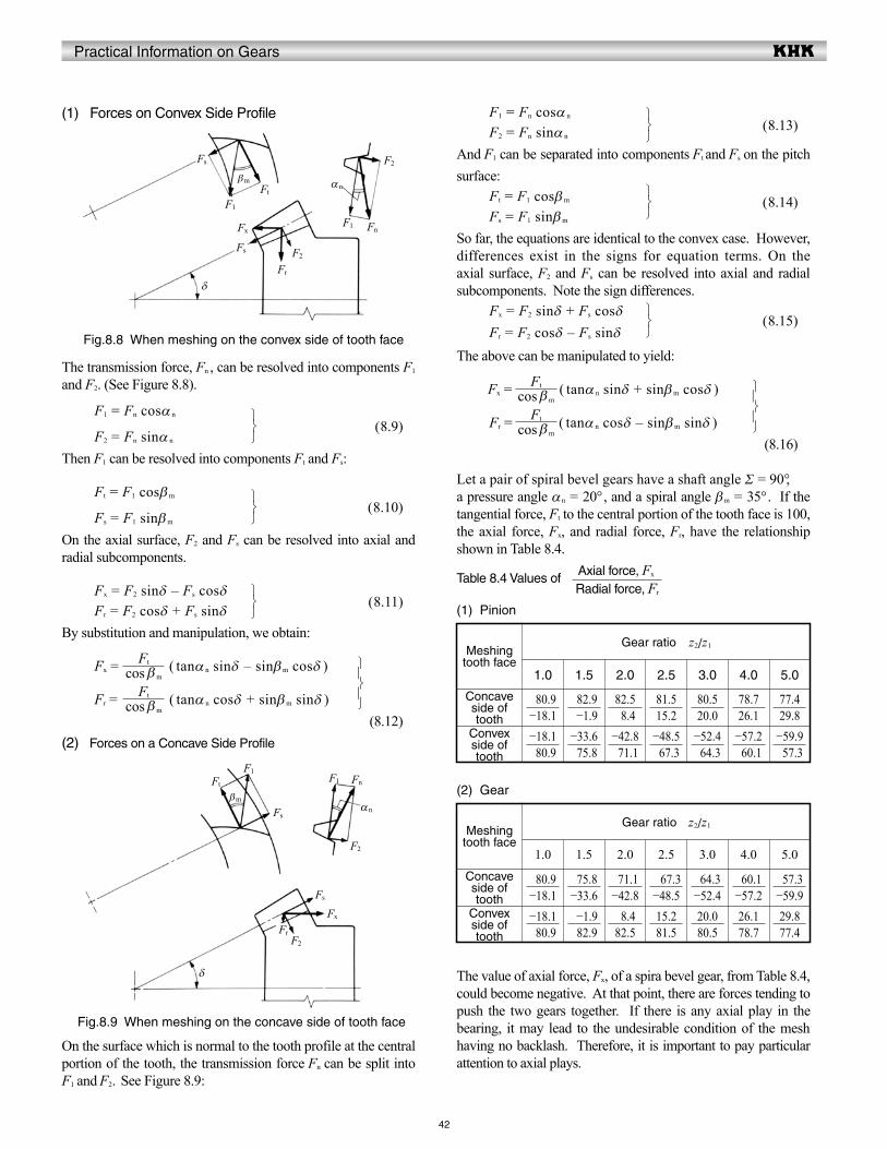
Practical Information on Gears
42
(1) Forces on Convex Side Profile F1 = Fn cosα n
F2 = Fn sinα n
And F1 can be separated into components Ft and Fs on the pitch surface: Ft = F1 cosβm
Fs = F1 sinβm
So far, the equations are identical to the convex case. However, differences exist in the signs for equation terms. On the axial surface, F2 and Fs can be resolved into axial and radial subcomponents. Note the sign differences. Fx = F2 sinδ + Fs cosδ Fr = F2 cosδ – Fs sinδ
The above can be manipulated to yield:
Fx = ( tanα n sinδ + sinβm cosδ )
Fr = ( tanα n cosδ – sinβm sinδ ) (8.16)
Let a pair of spiral bevel gears have a shaft angle Σ = 90° , a pressure angle αn = 20° , and a spiral angle βm = 35° . If the tangential force, Ft to the central portion of the tooth face is 100, the axial force, Fx, and radial force, Fr, have the relationship shown in Table 8.4.
Table 8.4 Values of
The transmission force, Fn , can be resolved into components F1 and F2. (See Figure 8.8).
F1 = Fn cosα n
F2 = Fn sinα n
Then F1 can be resolved into components Ft and Fs:
Ft = F1 cosβm
Fs = F1 sinβm
On the axial surface, F2 and Fs can be resolved into axial and radial subcomponents.
Fx = F2 sinδ – Fs cosδ Fr = F2 cosδ + Fs sinδBy substitution and manipulation, we obtain:
Fx = ( tanα n sinδ – sinβm cosδ )
Fr = ( tanα n cosδ + sinβm sinδ ) (8.12)(2) Forces on a Concave Side Profile
(8.9)
(8.10)
(8.11)
On the surface which is normal to the tooth profile at the central portion of the tooth, the transmission force Fn can be split into F1 and F2. See Figure 8.9:
(8.13)
(8.14)
(8.15)
(1) Pinion
Meshing tooth face
Concave side of tooth
Convex side of tooth
Gear ratio z2/z1
1.0
80.9−18.1
82.9 −1.9
82.5 8.4
81.515.2
80.520.0
78.726.1
77.429.8
−18.1 80.9
−33.6 75.8
−42.8 71.1
−48.5 67.3
−52.4 64.3
−57.2 60.1
−59.9 57.3
1.5 2.0 2.5 3.0 4.0 5.0
(2) Gear
Meshing tooth face
Concave side of tooth
Convex side of tooth
Gear ratio z2/z1
1.0
80.9−18.1
75.8−33.6
71.1−42.8
67.3−48.5
64.3−52.4
60.1−57.2
57.3−59.9
−18.1 80.9
−1.9 82.9
8.482.5
15.281.5
20.080.5
26.178.7
29.877.4
1.5 2.0 2.5 3.0 4.0 5.0
The value of axial force, Fx, of a spira bevel gear, from Table 8.4, could become negative. At that point, there are forces tending to push the two gears together. If there is any axial play in the bearing, it may lead to the undesirable condition of the mesh having no backlash. Therefore, it is important to pay particular attention to axial plays.
cos βm
Ft
cos βm
Ft
cos βm
Ft
cos βm
Ft
Radial force, Fr
Axial force, Fx
Fig.8.8 When meshing on the convex side of tooth face
Fig.8.9 When meshing on the concave side of tooth face
F1 Fn
Fr
αn
F2
F2
Fx
Fs
Fs
F1
Ft
βm
δ
F1Fn
Fr
αn
F2
F2
Fx
Fs
Fs
F1Ft
βm
δ
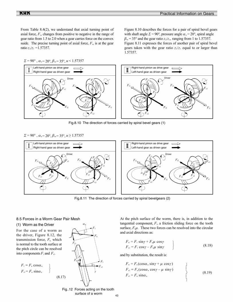
Practical Information on Gears
43
From Table 8.4(2), we understand that axial turning point of axial force, Fx, changes from positive to negative in the range of gear ratio from 1.5 to 2.0 when a gear carries force on the convex suide. The precise turning point of axial force, Fx, is at the gear ratio z2/z1 =1.57357.
Figure 8.10 describes the forces for a pair of spiral bevel gears with shaft angle Σ = 90° , pressure angle αn = 20° , spiral angle βm = 35° and the gear ratio z2/z1, ranging from 1 to 1.57357. Figure 8.11 expresses the forces of another pair of spiral bevel gears taken with the gear ratio z2/z1 equal to or larger than 1.57357.
8.5 Forces in a Worm Gear Pair Mesh
(1) Worm as the Driver
For the case of a worm as the driver, Figure 8.12, the transmission force, Fn, which is normal to the tooth surface at the pitch circle can be resolved into components F1 and Fr1.
F1 = Fn cosα n
Fr1 = Fn sinα n
(8.17)
At the pitch surface of the worm, there is, in addition to the tangential component, F1, a friction sliding force on the tooth surface, Fnm. These two forces can be resolved into the circular and axial directions as:
Ft1 = F1 sinγ + Fnm cosγ Fx1 = F1 cosγ – Fnm sinγ
and by substitution, the result is:
Ft1 = Fn (cosα n sinγ + m cosγ ) Fx1 = Fn (cosα n cosγ – m sinγ ) Fr1 = Fn sinα n
(8.18)
(8.19)
Σ = 90° , αn = 20°, βm = 35°, u < 1.57357
Σ = 90° , αn = 20°, βm = 35°, u ≥ 1.57357
Fig.8.10 The direction of forces carried by spiral bevel gears (1)
Fig.8.11 The direction of forces carried by spiral bevelgears (2)
Ft2
Left-hand pinion as drive gear
Right-hand gear as driven gear
Right-hand pinion as drive gear
Left-hand gear as driven gear
Ft1Fx1
Fr1
Fx2
Fr2 Ft1
Ft2
Fx2
Fr1
Fx1
Fr2
Ft2
Ft1
Fx2
Fr1
Fx1
Fr2
Ft1
Ft2Fx1
Fr1
Fx2
Fr2
Driver Driver
Ft2
Left-hand pinion as drive gear
Right-hand gear as driven gear
Right-hand pinion as drive gear
Left-hand gear as driven gear
Ft1 Fx1Fr1
Fx2Fr2 Ft1
Ft2
Fx2
Fr1
Fx1
Fr2
Ft2
Ft1
Fx2
Fr1
Fx1
Fr2
Ft1
Ft2 Fx1Fr1
Fx2Fr2
Driver Driver
Fn
αn
F1
F1
Fr1
Ft1
Fx1
Fn μ
γ
Fig..12 Forces acting on the tooth surface of a worm
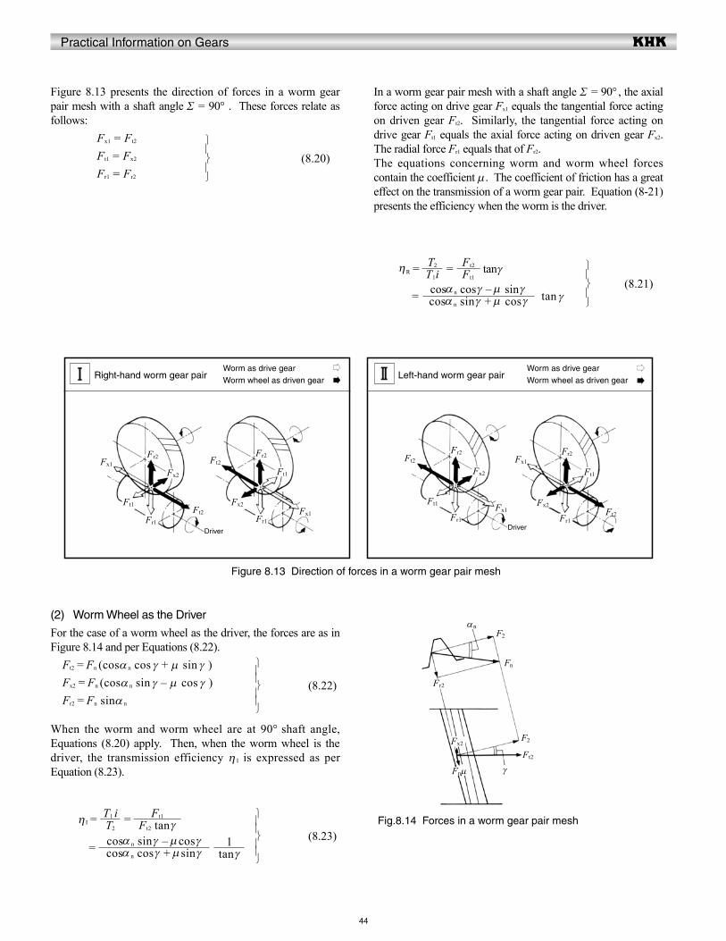
Practical Information on Gears
44
Figure 8.13 presents the direction of forces in a worm gear pair mesh with a shaft angle Σ = 90° . These forces relate as follows: Fx1 = Ft2
Ft1 = Fx2
Fr1 = Fr2
In a worm gear pair mesh with a shaft angle Σ = 90° , the axial force acting on drive gear Fx1 equals the tangential force acting on driven gear Ft2. Similarly, the tangential force acting on drive gear Ft1 equals the axial force acting on driven gear Fx2. The radial force Fr1 equals that of Fr2.The equations concerning worm and worm wheel forces contain the coefficient m. The coefficient of friction has a great effect on the transmission of a worm gear pair. Equation (8-21) presents the efficiency when the worm is the driver.
ηR = = tanγ
= tan γ
(8.20)
(8.21)
(2) Worm Wheel as the Driver
For the case of a worm wheel as the driver, the forces are as in Figure 8.14 and per Equations (8.22). Ft2 = Fn (cosα n cos γ + m sin γ ) Fx2 = Fn (cosα n sin γ – m cos γ ) Fr2 = Fn sinα n
When the worm and worm wheel are at 90° shaft angle, Equations (8.20) apply. Then, when the worm wheel is the driver, the transmission efficiency η I is expressed as per Equation (8.23).
η I = =
=
(8.22)
(8.23)
T1iT2
cosα n sin γ + m cos γcosα n cos γ – m sin γ
Ft1
Ft2
T2
T1 i
cosα n cos γ + msin γcosα n sin γ – mcos γ
Ft2 tan γFt1
tan γ1
Figure 8.13 Direction of forces in a worm gear pair mesh
Fig.8.14 Forces in a worm gear pair mesh
Worm as drive gearWorm wheel as driven gearRight-hand worm gear pair
Worm as drive gearWorm wheel as driven gearLeft-hand worm gear pair
Ft2Ft1
Fx1
Fr1
Fx2
Fr2
Ft1
Ft2
Fx2
Fr1Fx1
Fr2
Driver Driver
Ft1
Ft2
Fx2
Fr1
Fx1
Fr2
Fx2
Fx1
Fr1
Fr2
Ft2
Ft1
Fn
αn
Fr2
Fnm γ
F2
Fx2F2
Ft2

Practical Information on Gears
45
8.6 Forces in a Screw Gear Mesh
The forces in a screw gear mesh are similar to those in a worm gear pair mesh. For screw gears that have a shaft angle Σ = 90° , merely replace the worm's lead angle γ, in Equation (8.22), with the screw gear's helix angle β1.
In the general case when the shaft angle is not 90° , as in Figure 8.15, the driver screw gear has the same forces as for a worm mesh. These are expressed in Equations (8.24).
Ft1 = Fn (cos α n cos β 1 + msin β 1) Fx1 = Fn (cos α n sin β 1 – mcos β 1) Fr1 = Fn sin α n
Forces acting on the driven gear can be calculated per Equations (8.25).
Ft2 = Fx1 sinΣ + Ft1 cosΣ Fx2 = Ft1 sinΣ – Fx1 cosΣ Fr2 = Fr1
If the Σ term in Equation (8.25) is 90°, it becomes identical to Equation (8.20). Figure 8.16 presents the direction of forces in a screw gear mesh when the shaft angle Σ = 90° , and β1 = β2 = 45° .
(8.24)
(8.25)
Fig.8.15 The forces in a screw gear mesh
Fig.8.16 Direction of forces in a screw gear mesh
Fx2Ft2
Ft1
Fx1I
II
II
I
β1
β2
Σ
Pinion as drive gearGear as driven gearRight-hand gear
Pinion as drive gearGear as driven gearLeft-hand gear
Ft2Ft1
Fx2
Fr1
Fx1 Fr2
Driver
Ft2 Ft1
Fx2 Fr1 Fx1
Fr2Ft2
Ft1
Fx2
Fr1Fx1
Fr2
Ft2
Ft1
Fx2 Fr1
Fx1 Fr2
Driver
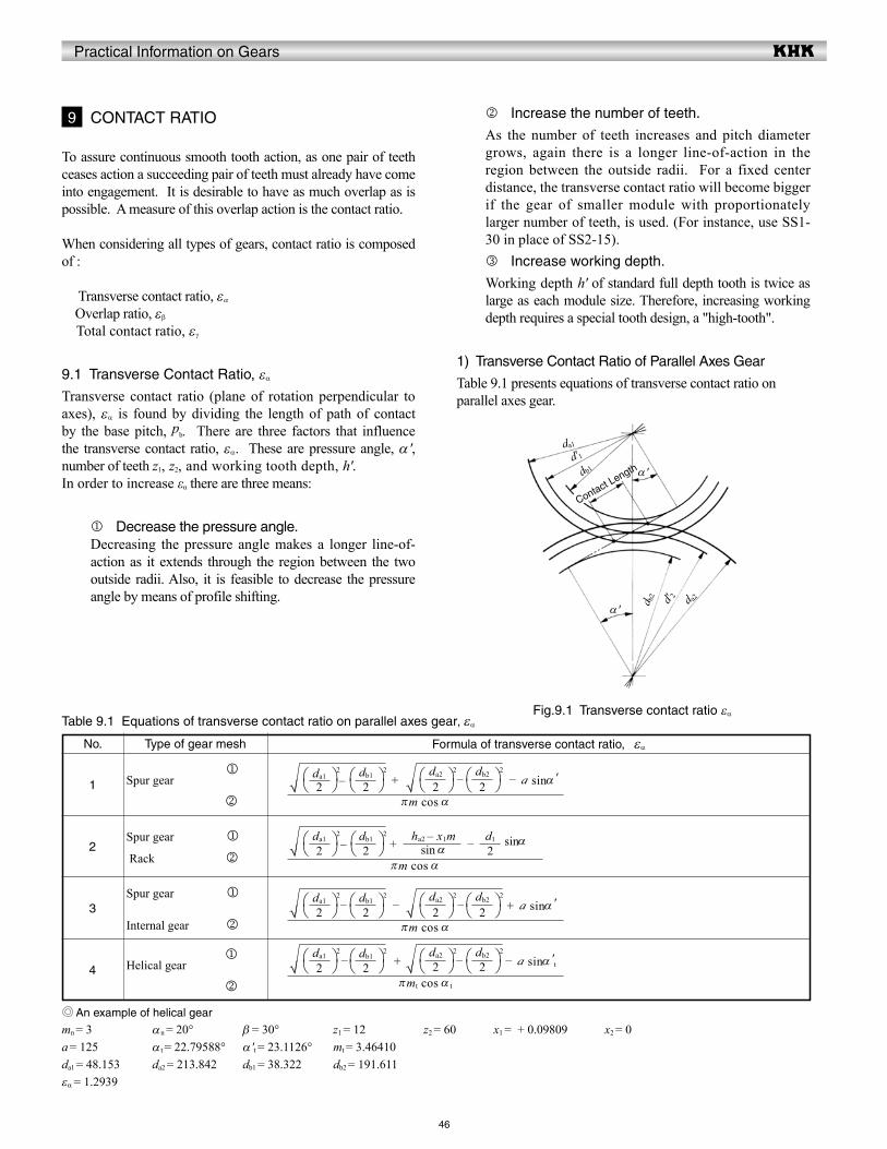
Practical Information on Gears
No.
46
k Increase the number of teeth.
As the number of teeth increases and pitch diameter grows, again there is a longer line-of-action in the region between the outside radii. For a fixed center distance, the transverse contact ratio will become bigger if the gear of smaller module with proportionately larger number of teeth, is used. (For instance, use SS1-30 in place of SS2-15).l Increase working depth.
Working depth h' of standard full depth tooth is twice as large as each module size. Therefore, increasing working depth requires a special tooth design, a "high-tooth".
1) Transverse Contact Ratio of Parallel Axes Gear
Table 9.1 presents equations of transverse contact ratio on parallel axes gear.
To assure continuous smooth tooth action, as one pair of teeth ceases action a succeeding pair of teeth must already have come into engagement. It is desirable to have as much overlap as is possible. A measure of this overlap action is the contact ratio.
When considering all types of gears, contact ratio is composed of :
Transverse contact ratio, εα
Overlap ratio, εβ Total contact ratio, εγ
9.1 Transverse Contact Ratio, εα
Transverse contact ratio (plane of rotation perpendicular to axes), εα is found by dividing the length of path of contact by the base pitch, pb. There are three factors that influence the transverse contact ratio, εα. These are pressure angle, α ', number of teeth z1, z2, and working tooth depth, h'.In order to increase εα there are three means:
j Decrease the pressure angle.Decreasing the pressure angle makes a longer line-of-action as it extends through the region between the two outside radii. Also, it is feasible to decrease the pressure angle by means of profile shifting.
9 CONTACT RATIO
Table 9.1 Equations of transverse contact ratio on parallel axes gear, εα
1
2
3
4
Type of gear mesh
jSpur gear
k
Spur gear j
Rack k
Spur gear j
Internal gear k
jHelical gear
k
Formula of transverse contact ratio, εα
An example of helical gear
mn = 3a = 125da1 = 48.153εα = 1.2939
αn = 20°α t = 22.79588°da2 = 213.842
β = 30°α 't = 23.1126°db1 = 38.322
z1 = 12mt = 3.46410db2 = 191.611
z2 = 60 x1 = + 0.09809 x2 = 0
πm cos α
– + – – a sinα '2
da1 2
√ 2
db1 2
2
da2 2
√ 2
db2 2
πm cos α
– – – + a sinα '2
da1 2
√ 2
db1 2
2
da2 2
√ 2
db2 2
πmt cos α t
– + – – a sinα 't2da1 2
√ 2
db1 2
2
da2 2
√ 2
db2 2
πm cos α
– + – sinα2
da1 2
√ 2
db1 2
sin α
ha2 – x1m2d1
Fig.9.1 Transverse contact ratio εα
da1
α '
α '
d'1db1
d a2d' 2d b2
Contact Length
Practical Information on Gears
No.
No.
47
(2) Transverse Contact Ratio of Bevel Gears, εα
The transverse contact ratio of a bevel gear pair, εα can be derived from consideration of the equivalent spur gears, when viewed from the back cone. (See Figure 4.9 on page 404.)Table 9.2 presents equations calculating the transverse contact ratio.Table 9.2 Equations for transverse contact ratio for a bevel gear pair, εα
1
2
3
4
Item
Back cone distance
Base radius of an equivalent spur gear
Tip radius of an equivalent spur gear
Transverse contact ratio
Symbol
Rv
Rvb
Rva
εα
Equations for Contact Ratio
Straight bevel gearRvcosα
Spiral bevel gearRvcosα t
Rv + ha
Straight bevel gear
Spiral bevel gear
An example of spiral bevel gearm = 3 , α n = 20° , β = 35° , z1 = 20 , z2 = 40 , α t = 23.95680°d1 = 60 , d2 = 120 , Rv1=33.54102 , Rv2 = 134.16408Rvb1 = 30.65152 , Rvb2 = 122.6061, ha1 =3.4275 , ha2 = 1.6725Rva1 = 36.9685 , Rva2 = 135.83658εα = 1.2825
(3) Transverse Contact Ratio For Nonparallel and Nonintersecting Axes Gear Pairs, εα
Table 9.3 presents equations for contact ratio, εα, of nonparallel and nonintersecting gear meshes.The equations are approximations by considering the worm gear pair mesh in the plane perpendicular to worm wheel axis and likening it to spur gear and rack mesh.
Table 9.3 Equations for transverse contact ratio of nonparallel and nonintersecting meshes, εα
1
Type of gear mesh
Worm j
Worm wheel k
Equation of transverse contact ratio, εα
An example of worm gear pair meshmx = 3 , α n = 20° , z1 = 2 , z2 = 30d1 = 44 , d2 = 90 , γ = 7.76517°α x = 20.17024° , ha1 = 3dt = 96 , db2 = 84.48050εα = 1.8066
2cosδd
πm cosα Rva1
2 – Rvb12 + Rva2
2 – Rvb2
2 – ( Rv1+Rv2 ) sinα√ √
πm cos α t
Rva12 – Rvb1
2 + Rva22 – Rvb2
2 – ( Rv1+Rv2 ) sinα t√ √
πmx cosαx
+ – – sinα xsinα x
ha12– xt2 mx
2dt 2
√ 2
db2 2
2
d2

Practical Information on Gears
48
9.2 Overlap Ratio, εβ
Helical gears and spiral bevel gears have an overlap of tooth action in the axial direction. Overlap ratio is obtained by dividing gear width, b, by px , the axial pitch. (See the illustration in Figure 9.2.) Equations for calculating overlap ratio are presented in Table 9.4.
Table 9.4 Equation for overlap ratio, εβ
No.
1
2
Type of Gear
Helical gear
Spiral bevel gear
Equation Example
b = 50 , β = 30°, mn = 3εβ =2.6525
From Table 4.21 (Page 409): R = 67.08204 , b = 20 , βm = 35°, m = 3εβ =1.7462
NOTE: The module m in spiral bevel gear equation is the transverse module.
πmn
b sinβ
R – 0.5bR
πmb tan β m
Fig.9.2 Overlap ratio, εβ
px
β
b
p n
Practical Information on Gears
49
(6) Use Small GearslAdopt smaller module gears and smaller tip diameter gears.
(7) Use High-Rigidity GearslIncreasing face width can give a higher rigidity that will help
in reducing noise.lReinforce housing and shafts to increase rigidity.
(8) Use High-Vibration-Damping MateriallPlastic gears will be quiet in light load, low speed operation.
Care should be taken, however, to the reduced ability to operate at elevated temperatures.lCast iron gears have lower noise than steel gears.
(9) Apply Suitable LubricationlLubricate gears sufficiently.lHigh-viscosity lubricant will have the tendency to reduce the
noise.
(10) Lower Load and SpeedlLowering rotational speed and load as far as possible will
reduce gear noise.
There are several causes of noise. The noise and vibration in rotating gears, especially at high loads and high speeds, need to be addressed. Following are ways to reduce the noise. These points should be considered in the design stage of gear systems.
(1) Use High-Precision GearslReduce the pitch error, tooth profile error, runout error and
lead error.lGrind teeth to improve the accuracy as well as the surface
finish.
(2) Use Better Surface Finish on GearslGrinding, lapping and honing the tooth surface, or running
in gears in oil for a period of time can also improve the smoothness of tooth surface and reduce the noise.
(3) Ensure a Correct Tooth ContactlCrowning and end relief can prevent edge contact.lProper tooth profile modification is also effective.lEliminate impact on tooth surface.
(4) Have A Proper Amount of BacklashlA smaller backlash will help reduce pulsating transmission.lA bigger backlash, in general, causes less problems.
(5) Increase the Contact RatiolBigger contact ratio lowers the noise. Decreasing pressure
angle and/or increasing tooth depth can produce a larger contact ratio.lEnlarging overlap ratio will reduce the noise. Because of this
relationship, a helical gear is quieter than the spur gear and a spiral bevel gear is quieter than the straight bevel gear.
10 GEAR NOISE
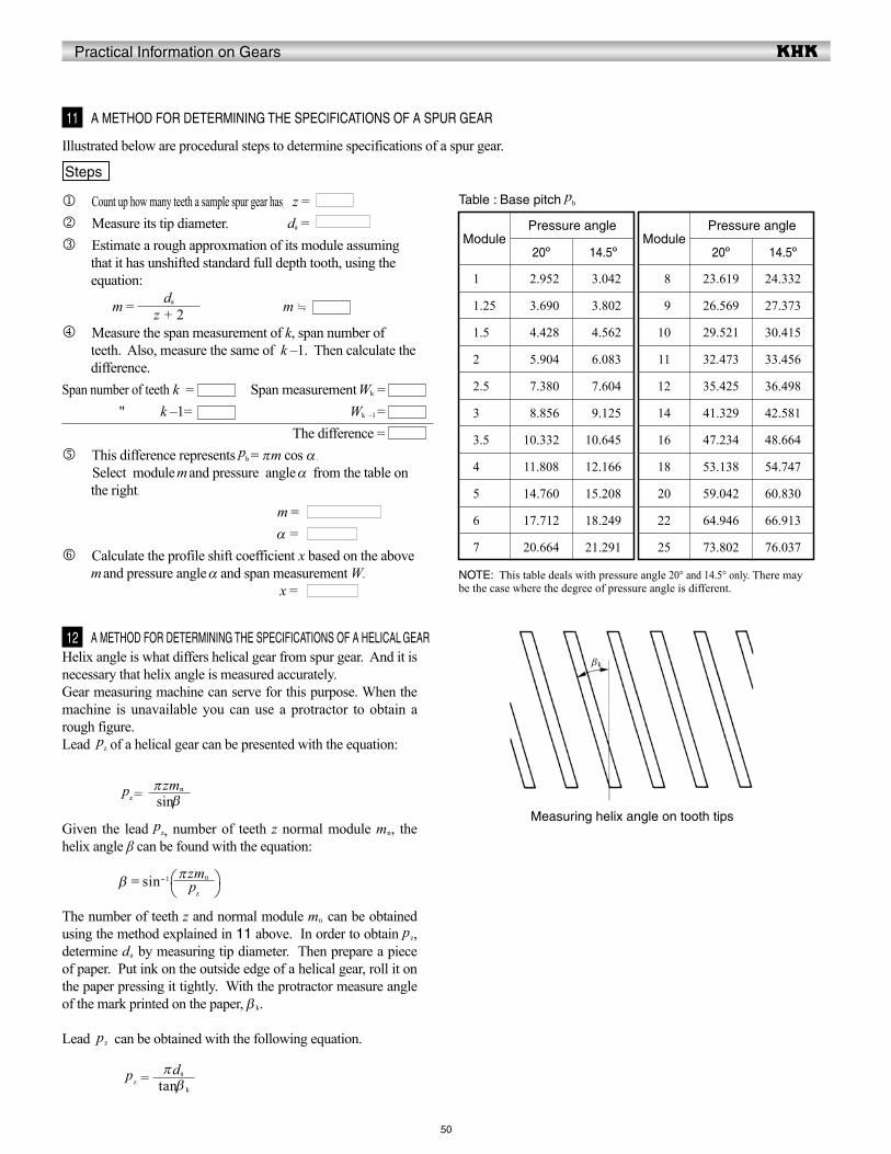
Practical Information on Gears
Helix angle is what differs helical gear from spur gear. And it is necessary that helix angle is measured accurately.Gear measuring machine can serve for this purpose. When the machine is unavailable you can use a protractor to obtain a rough figure.Lead pz of a helical gear can be presented with the equation:
pz =
Given the lead pz, number of teeth z normal module mn, the helix angle β can be found with the equation:
β = sin-1
The number of teeth z and normal module mn can be obtained using the method explained in 11 above. In order to obtain pz, determine da by measuring tip diameter. Then prepare a piece of paper. Put ink on the outside edge of a helical gear, roll it on the paper pressing it tightly. With the protractor measure angle of the mark printed on the paper, β k.
Lead pz can be obtained with the following equation.
pz =
j Count up how many teeth a sample spur gear has. z = k Measure its tip diameter. da =l Estimate a rough approxmation of its module assuming
that it has unshifted standard full depth tooth, using the equation:
m = m
m Measure the span measurement of k, span number of teeth. Also, measure the same of k –1. Then calculate the difference.
Span number of teeth k = Span measurement Wk = " k –1= Wk –1 = The difference =n This difference represents pb = πm cos α .
Select module m and pressure angle α from the table on the right.
m = α =o Calculate the profile shift coefficient x based on the above
m and pressure angle α and span measurement W. x =
50
Table : Base pitch pb
Illustrated below are procedural steps to determine specifications of a spur gear.
11 A METHOD FOR DETERMINING THE SPECIFICATIONS OF A SPUR GEAR
Steps
12 A METHOD FOR DETERMINING THE SPECIFICATIONS OF A HELICAL GEAR
Module
1.00
1.25
1.50
2.00
2.50
3.00
3.50
4.00
5.00
6.00
7.00
Module
08
09
10
11
12
14
16
18
20
22
25
Pressure angle Pressure angle
20º
02.952
03.690
04.428
05.904
07.380
08.856
10.332
11.808
14.760
17.712
20.664
20º
23.619
26.569
29.521
32.473
35.425
41.329
47.234
53.138
59.042
64.946
73.802
14.5º
03.042
03.802
04.562
06.083
07.604
09.125
10.645
12.166
15.208
18.249
21.291
14.5º
24.332
27.373
30.415
33.456
36.498
42.581
48.664
54.747
60.830
66.913
76.037
NOTE: This table deals with pressure angle 20° and 14.5° only. There may be the case where the degree of pressure angle is different.
z + 2da
tanβ k
πda
pz
πzmn
sinβπzmn
Measuring helix angle on tooth tips
βk
.= .