prd 1/79 - the national board of boiler and pressure ... meetings/agenda... · 2 nbic part 4...
TRANSCRIPT

PRD 1/79

PRD 2/79

PRD 3/79

PRD 4/79
PRD 5/79

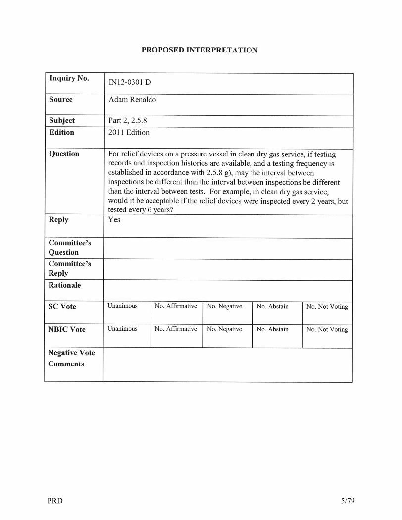
����������� ���������������������������������������� � �!�"�#$�� �"�"��������!����������� ����#%��&'�$��������%����""#���(����������)���"����*+��� ����,��$&��������-������.�/������!����#)�01 )21�2� 3�(# 001)��1�2)��&��#%��&4$�����5���(������&� 67���#���������������������������������� 8 �"�����#�����6���" ,,�"�����"!�����������"����� �����"������ 9�:���"������ ����� &����;��"�3��� �����<�"���" ,,�"�����"����� �������"�&��"���" ,,�"�����"!���������� ����=���!�"��$�!�#.�"8 �"�����#>�����"�������"���?����"!��������"�����"����@���6��������, ������"������ 9,:6� "�����"��6�"���"!�����������"����� �����"��@�����" ,,�"������� �����",�@���������6������� 9�:=���!�"��$�!�#.�"8 �"����A#3���������@���"���!��"" ��@�""����������,�""��@��������"���,������"����@���6��������"���,���� �����"�"��6�"���������������-������� 9,:�&����������@�6��-����������@�����"�"�(���������"=���!�"��$�!�#.�"8 �"����/#3���������@���"���!��"" ��@�""����������,�""��@��������"���,������"�����"!��������"�����"����@���6��������"���,���� �����"�"��6�"���������������-������� 9,:�&����������@�6��-�����"!������"6����������������������@�6��-�����"�"�3���(�&!�����������,�""��@����-� ���6�����!��6�������������@���"-�����"!������@��������"�6 ���"����@���0����"=���!�"��$�!�#.�"8 �"�����#B���������!��6��������@�����"������@���"6����"��6�"���!������ 9,:��"������!��6�����!�������������@���"-�����-��@���"������"�&�&�*������"�,��������"��6�"�����"����� ��������� ����"���,����������@���"=3���(�&!�����������,�""��@����-� ���6�����!��6�������������@���"-�����"!������@��������"������!�����@���0����"���� ��� ���������"���,�-���������&"�&!�����!������@���"6���,6������"�����������&�������01���������@��""������!��6�=���!�"��$�!�#.�"
PRD 6/79

���*,�� ��#�(���!����&���������������������������������� ������������������� ������ ������� ������������ ��� ������� ����������������������������������������������� ������ ������������������������� �� ��� ����� �������������� �� ���� ���������� ���������������� ��� ����� ������������ ����� ���� �������� ��� ������� ������ ������������������� ���������� ������� �������������������������� ����������������������������������������� �� ������ ��� ������� ��� ����������������������� ��� ���������������� ������� ����������������� ������������������������ � ���� ������� ������������� �����������������������!� ��� ������� �� ������������ �����������������"
���#���������� ������ ������� �� ��$����� ����������������������� �������������� ������ �������������������������� ��� ������������������� ��� ��������� ������������ ������������ ������� �� ��������%������������������ ��������� ���&� �������������� ���� ����"�'��(��������� ����������� ��)�*��+��������������������� ��� ������� �������������������������� ������������������� ��������� �����������������)�,��+������ ����� �������������������� �������-
PRD 7/79

1
SC-PRD ITEM NB11-0401, Draft 4-25-12 Open Issues: 1. Editorial items A. Renumbering needs to be checked B. All cross references need to be checked/updated C. Index not complete D. Several tables did not import correctly Organizational Comments: 1. Part 3 supplement 7 has been changed to main body text, and rearranged for flow 2. Administrative requirements moved after general repair requirements Editorial/ other comments
1. Safety valve and safety relief valve changed to “pressure relief valve” where appropriate 2. “mounted” changed to “installed” in numerous locations 3. Organic fluid heater pressure relief requirements expanded based upon Section I of ASME Code 4. Does not include NBIC changes that have been approved by the committee but not yet published
Key: Italics indicate new material written for this draft Strikethrough indicates deleted material (Parenthetical notes are for information only, and are not to be included in publications) Document: NBIC Part 4 draft4-12.doc
PRD 8/79

2
NBIC PART 4
PRESSURE RELIEF DEVICES
Table of Contents (TO BE COMPLETED)
1.0 Installation of Pressure Relief Devices 1.1 Pressure Relief Valves For Boilers 1.1.1 Valve Requirements — General/Definitions 1.1.1.1 Number 1.1.1.2 Location 1.1.1.3 Capacity 2.0 In-Service Inspection of Pressure Relief Devices 3.0 Repair of Pressure Relief Devices (following index is incorrect) 1.7 Accreditation of “VR” Repair Organizations......................................................
1.7.1 Scope ................................................................................................ 1.7.2 Jurisdictional Participation ................................................................. 1.7.3 General Rules .................................................................................... 1.7.4 Repair of Nuclear Valves ................................................................... 1.7.5 Issuance and Renewal of the “VR” Certificate of Authorization ..........
1.7.5.1 General................................................................................ 1.7.5.2 Issuance of Certificate.......................................................... 1.7.5.3 Renewal of Certificate.......................................................... 1.7.5.4 Review of Applicant’s Facility.............................................. 1.7.5.5 Verification Testing.............................................................. 1.7.5.6 Verification Testing Alternatives...........................................
1.7.6 Use of the “VR” Authorization ........................................................... 1.7.6.1 Technical Requirements...................................................... 1.7.6.2 Stamp Use.......................................................................... 1.7.6.3 Return of Stamp.................................................................. 1.7.6.4 Multiple Locations.............................................................. 1.7.6.5 Certificate of Authorization Contents ................................. 1.7.6.6 Changes to Certificates of Authorization............................. 1.7.6.7 Issuance of More Than One “VR” Symbol Stamp to a
Certificate of Authorization Holder..................................... 1.7.7 Quality System .................................................................................
1.7.7.1 General.............................................................................. 1.7.7.2 Written Description ........................................................... 1.7.7.3 Review............................................................................... 1.7.7.4 Maintenance of Controlled Copy....................................... 1.7.7.5 Outline of Requirements for a Quality System...................
1.7.8 ASME “V,” “HV,” or “UV” Certificate Holders ................................. Section 4 Examination and Testing......................................................................... 4.1 Scope .............................................................................................................. 4.5 Pressure Relief Valve Performance Testing and Testing Equipment ..................
4.5.1 Test Medium and Testing Equipment ................................................ 4.5.2 Owner-User ASME Code Section VIII Steam Testing ........................ 4.5.3 Lift Assist Testing ............................................................................... 4.5.4 Pressure Test of Parts ..........................................................................
PRD 9/79

3
Section 5 Certification/Documentation and Stamping.............................................. 5.1 Scope ............................................................................................................... 5.9 Stamping Requirements for Pressure Relief Devices ..........................................
5.9.1 Nameplates ........................................................................................ 5.9.2 Repair Nameplate .............................................................................. 5.9.3 Changes to Original Pressure Relief Valve Nameplate Information .... 5.9.4 Test Only Nameplate ......................................................................... 5.9.5 Replacement of Illegible or Missing Nameplates ….............................. 5.10 Alternative Marking and Stamping for Graphite Pressure Equipment ….
Section 6 Supplements........................................................................................... Supp. 7 Requirements for Repairs to Pressure Relief Devices .................................
S7.1 Scope ................................................................................................. S7.2 General Requirements ........................................................................ S7.4 Materials for Pressure Relief Devices .................................................. S7.5 Replacement Parts for Pressure Relief Devices .................................... S7.6 Initial Adjustments to Pressure Relief Valves ....................................... S7.7 Field Repair ........................................................................................ S7.8 Audit Requirements ............................................................................ S7.9 Use of Owner-User Personnel ............................................................ S7.10 Guide to Jurisdictions for Authorization of Owners-Users to Make
Adjustments to Pressure Relief Valves .............................................. S7.10.1 General ............................................................................. S7.10.2 Training ............................................................................. S7.10.3 Documentation .................................................................. S7.10.4 Quality System ................................................................... S7.10.5 External Adjustments .......................................................... S7.10.6 Repairs ...............................................................................
S7.11 Training and Qualification of Personnel ........................................................ S7.11.1 General .......................................................................................... S7.11.2 Contents of Training Program ......................................................... S7.11.3 Qualification of Personnel .............................................................. S7.11.4 Annual Review of Qualification ......................................................
S7.12 Welding for Pressure Relief Valves ................................................................. S7.12.1 Welding Procedure Specifications ................................................... S7.12.2 Standard Welding Procedure Specifications .................................... S7.12.3 Performance Qualification .............................................................. S7.12.4 Welding Records ............................................................................. S7.12.5 Welders’ Identification .................................................................... S7.12.6 Welders’ Continuity ........................................................................ S7.3 Weld Repairs to Pressure Relief Valve Parts ........................................
S7.13 Heat Treatment .............................................................................................. S7.13.1 Preheating .......................................................................................
S7.13.2 Postweld Heat Treatment ................................................................. S7.14 Recommended Procedures for Repairing Pressure Relief Valves .....................
S7.14.1 Introduction .................................................................................... S7.14.2 Spring-Loaded Pressure Relief Valves .............................................. S7.14.3 Pilot Operated Pressure Safety Relief Valves ..................................................
Supp. 8 Recommended Guide for the Design of a Test System for Pressure Relief Devices in Compressible Fluid Service ........................................................... S8.1 Introduction ................................................................................................... S8.2 General .......................................................................................................... S8.3 Test System Description ................................................................................. S8.4 Test Vessel Sizing Data ................................................................................... S8.5 Tables, Charts, and Figures ............................................................................. Supp. 9 Procedures to Extend the “VR” Certificate of Authorization and Stamp to ASME “NV” Stamped Pressure Relief Devices .................................................... S9.1 Introduction ................................................................................................... S9.2 Administrative Procedures ............................................................................. S9.3 General Rules ................................................................................................
PRD 10/79

4
INTRODUCTION
This Part of the NBIC addresses requirements for the installation, in-service inspection, and repair of pressure relief devices used for the overpressure protection of pressure retaining items (PRI). (NOTE: Include Forward, Committee member Information, copyright information, introduction (up to XVIII), table of contents (All as part of Introduction) Also include information on jurisdictional oversight. Part 1, Par 1.1 through 1.4.4 Glossary, Interpretations, Index to be at end of document)
National Board Inspection Code 2013 Edition Date of Issue — July 31, 2013 This code was developed under procedures accredited as meeting the criteria for American National Standards. The Consensus Committee that approved the code was balanced to ensure that individuals from competent and concerned interests had an opportunity to participate. The proposed code was made available for public review and comment, which provided an opportunity for additional public input from industry, academia, regulatory and jurisdictional agencies, and the public-at-large. The National Board does not “approve,” “rate,” or “endorse” any item, construction, proprietary device, or activity. The National Board does not take any position with respect to the validity of any patent rights asserted in connection with any items mentioned in this document, and does not undertake to insure anyone utilizing a standard against liability for infringement of any applicable Letters Patent, nor assume any such liability. Users of a code are expressly advised that determination of the validity of any such patent rights, and the risk of infringement of such rights, is entirely their own responsibility. Participation by federal agency representative(s) or person(s) affiliated with industry is not to be interpreted as government or industry endorsement of this code. The National Board accepts responsibility for only those interpretations issued in accordance with governing National Board procedures and policies that preclude the issuance of interpretations by individual committee members. The footnotes in this document are part of this American National Standard. R
R NR R R
®
The above National Board symbols are registered with the US Patent Office. “National Board” is the abbreviation for The National Board of Boiler and Pressure Vessel Inspectors. No part of this document may be reproduced in any form, in an electronic retrieval system or otherwise, without the prior written permission of the publisher.
PRD 11/79

5
Foreword The National Board of Boiler and Pressure Vessel Inspectors is an organization comprised of Chief Inspectors for the states, cities, and territories of the United States and provinces and territories of Canada. It is organized for the purpose of promoting greater safety to life and property by securing concerted action and maintaining uniformity in post-construction activities of pressure-retaining items, thereby ensuring acceptance and interchangeability among Jurisdictional authorities responsible for the administration and enforcement of various codes and standards. In keeping with the principles of promoting safety and maintaining uniformity, the National Board originally published The NBIC in 1946, establishing rules for inspection and repairs to boilers and pressure vessels. The National Board Inspection Code (NBIC) Committee is charged with the responsibility for maintaining and revising the NBIC. In the interest of public safety, the NBIC Committee decided, in 1995, to revise the scope of the NBIC to include rules for installation, inspection, and repair or alteration to boilers, pressure vessels, piping, and nonmetallic materials. In 2007, the NBIC was restructured into three Parts specifically identifying important postconstruction activities involving safety of pressure-retaining items. This restructuring provides for future expansion, transparency, and uniformity, ultimately improving public safety. The NBIC Committee’s function is to establish rules of safety governing post-construction activities for the installation, inspection and repair and alteration of pressure-retaining items, and to interpret these rules when questions arise regarding their intent. In formulating the rules, the NBIC Committee considers the needs and concerns of individuals and organizations involved in the safety of pressure-retaining items. The objective of the rules is to afford reasonably certain protection of life and property, so as to give a reasonably long, safe period of usefulness. Advancements in design and material and the evidence of experience are recognized. The rules established by the NBIC Committee are not to be interpreted as approving, recommending, or endorsing any proprietary or specific design, or as limiting in any way an organization’s freedom to choose any method that conforms to the NBIC rules. The NBIC Committee meets regularly to consider revisions of existing rules, formulation of new rules, and respond to requests for interpretations. Requests for interpretation must be addressed to the NBIC Secretary in writing and must give full particulars in order to receive Committee consideration and a written reply. Proposed revisions to the Code resulting from inquiries will be presented to the NBIC Committee for appropriate action. Proposed revisions to the Code approved by the NBIC Committee are submitted to the American National Standards Institute and published on the National Board Web site to invite comments from all interested persons. After the allotted time for public review and final approval the new edition is published. Organizations or users of pressure-retaining items are cautioned against making use of revisions that are less restrictive than former requirements without having assurance that they have been accepted by the Jurisdiction where the pressure-retaining item is installed. The general philosophy underlying the NBIC is to parallel those provisions of the original code of construction, as they can be applied to post-construction activities. The NBIC does not contain rules to cover all details of post-construction activities. Where complete details are not given, it is intended that individuals or organizations, subject to the acceptance of the Inspector and Jurisdiction when applicable, provide details for postconstruction activities that will be as safe as otherwise provided by the rules in the original Code of Construction. Activities not conforming to the rules of the original code of construction or the NBIC must receive specific approval of the Jurisdiction, who may establish requirements for design,
PRD 12/79

6
construction, inspection, testing, and documentation. There are instances where the NBIC serves to warn against pitfalls; but the Code is not a handbook, and cannot substitute for education, experience, and sound engineering judgment. It is intended that this Edition of the NBIC not be retroactive. Unless the Jurisdiction imposes the use of an earlier edition, the latest effective edition is the governing document.
Introduction It is the purpose of the National Board Inspection Code (NBIC) to maintain the integrity of pressure-retaining items by providing rules for installation, and after the items have been placed into service, by providing rules for inspection and repair and alteration, thereby ensuring that these items may continue to be safely used. The NBIC is intended to provide rules, information and guidance to manufacturers, Jurisdictions, inspectors, owner-users, installers, contractors, and other individuals and organizations performing or involved in post-construction activities, thereby encouraging the uniform administration of rules pertaining to pressure-retaining items. Scope The NBIC recognizes three important areas of post-construction activities where information, understanding, and following specific requirements will promote public and personal safety. These areas include: • Installation • Inspection • Repairs and Alterations The NBIC provides rules, information, and guidance for post-construction activities, but does not provide details for all conditions involving pressure-retaining items. Where complete details are not provided in this Code, the Code user is advised to seek guidance from the Jurisdiction and from other technical sources. The words shall, should, and may are used throughout the NBIC and have the following intent: • Shall – action that is mandatory and required. • Should – indicates a preferred but not mandatory means to accomplish the requirement unless specified by others such as the Jurisdiction. • May – permissive, not required or a means to accomplish the specified task. Organization The NBIC is organized into three Parts to coincide with specific post-construction activities involving pressure-retaining items. Each Part provides general and specific rules, information, and guidance within each applicable post-construction activity. Other NBIC Parts or other published standards may contain additional information or requirements needed to meet the rules of the NBIC. Specific references are provided in each Part to direct the user where to find this additional information. NBIC Parts are identified as: • Part 1, Installation – This Part provides requirements and guidance to ensure all types of pressure-retaining items are installed and function properly. Installation includes meeting specific safety criteria for construction, materials, design, supports, safety devices, operation, testing, and maintenance. • Part 2, Inspection – This Part provides information and guidance needed to perform and document inspections for all types of pressure-retaining items. This Part includes information on personnel safety, non-destructive examination, tests, failure mechanisms, types of pressure equipment, fitness for service, risk-based assessments, and performance-based standards.
PRD 13/79

7
• Part 3, Repairs and Alterations – This Part provides information and guidance to perform, verify, and document acceptable repairs or alterations to pressure-retaining items regardless of code of construction. Alternative methods for examination, testing, heat treatment, etc., are provided when the original code of construction requirements cannot be met. Specific acceptable and proven repair methods are also provided. • Part 4, Pressure Relief Devices – This part provides information and guidance on the installation, inservice inspection and repair of pressure relief devices. Each NBIC Part is divided into major Sections as outlined in the Table of Contents. Tables, charts, and figures provide relevant illustrations or supporting information for text passages, and are designated with numbers corresponding to the paragraph they illustrate or support within each Section. Multiple tables, charts, or figures referenced by the same paragraph will have additional letters reflecting the order of reference. Tables, charts, and figures are located in or after each major Section within each NBIC Part. Text Identification and Numbering Each page in the text will be designated in the top header with the publication’s name, part number, and part title. The numbering sequence for each section begins with the section number followed by a dot to further designate major sections (e.g., 1.1, 1.2, 1.3). Major sections are further subdivided using dots to designate subsections within that major section (e.g., 1.1.1, 1.2.1, 1.3.1). Subsections can further be divided as necessary. Paragraphs under sections or subsections shall be designated with small letters in parenthesis (e.g., a), b), c)) and further subdivided using numbers in parenthesis (e.g., 1), 2), 3)). Subdivisions of paragraphs beyond this point will be designated using a hierarchical sequence of letters and numbers followed by a dot. Example: 2.1 Major Section 2.1.1 Section 2.1.2 Section 2.1.2. Subsection a) paragraph b) paragraph 1) subparagraph 2) subparagraph a. subdivisions 1. subdivisions 2. subdivisions b. subdivisions 1. subdivisions 2. subdivisions Tables and figures will be designated with the referencing section or subsection identification. When more than one table or figure is referenced in the same section or subsection, letters or numbers in sequential order will be used following each section or subsection identification. Supplements Supplements are contained in each Part of the NBIC to designate information only pertaining to a specific type of pressure-retaining item (e.g., Locomotive Boilers, Historical Boilers, Graphite Pressure Vessels.) Supplements follow the same numbering system used for the main text only preceded by the Letter “S.” Each page of the supplement will identify the supplement number and name in the top heading.
PRD 14/79

8
Interpretations On request, the NBIC Committee will render an interpretation of any requirement of this Code. Interpretations are provided for each Part and are specific to the Code edition and addenda referenced in the interpretation. Interpretations provide information only and are not part of this Code. Jurisdictional Precedence Reference is made throughout this Code to the requirements of the “Jurisdiction.” Where any provision herein presents a direct or implied conflict with any jurisdictional regulation, the Jurisdictional regulation shall govern. Units of Measurement Both U.S. customary units and metric units are used in the NBIC. The value stated in U.S. customary units or metric units are to be regarded separately as the standard. Within the text, the metric units are shown in parentheses. In Supplement 6, Parts 2 and 3, Continued Service and Inspection of DOT Transport Tanks, the metric units are shown first with the U.S. customary units shown in parentheses. U.S. customary units or metric units may be used with this edition of the NBIC, but one system of units shall be used consistently throughout a repair or alteration of pressure-retaining items. It is the responsibility of National Board accredited repair organizations to ensure the appropriate units are used consistently throughout all phases of work. This includes materials, design, procedures, testing, documentation, and stamping. The NBIC policy for metrication is outlined in each part of the NBIC. Accreditation Programs The National Board administers and accredits three specific repair programs1 as shown below: “R”……….Repairs and Alterations to Pressure-Retaining Items “VR”……..Repairs to Pressure Relief Valves “NR”……..Repair and Replacement Activities for Nuclear Items Part 3, Repairs and Alterations, of the NBIC describes the administrative requirements for the accreditation of “R” and NR” repair organizations. Requirements for “VR” repair organziations are included in Part 4. The National Board also administers and accredits four specific inspection agency programs as shown below: New Construction Criteria for Acceptance of Authorized Inspection Agencies for New Construction (NB-360) Inservice Qualifications and Duties for Authorized Inspection Agencies (AIAs) Performing Inservice Inspection Activities and Qualifications for Inspectors of Boilers and Pressure Vessels (NB-369) Owner-User Accreditation of Owner-User Inspection Organizations (OUIO) (NB-371) Owners or users may be accredited for both a repair and inspection program provided the requirements for each accreditation program are met. Federal Government
PRD 15/79
9
Qualifications and Duties for Federal Inspection Agencies Performing Inservice Inspection Activities (FIAs) (NB-390) These programs can be viewed on the National Board Web site. For questions or further information regarding these programs contact: The National Board of Boiler and Pressure Vessel Inspectors 1055 Crupper Avenue Columbus, OH 43229-1183 Phone — 614.888.8320 Fax — 614.847.1828 Web site — www.nationalboard.org Certificates of Authorization for Accreditation Programs Any organization seeking an accredited program may apply to the National Board to obtain a Certificate of Authorization for the requested scope of activities. A confidential review shall be conducted to evaluate the organization’s quality system. Upon completion of the evaluation, a recommendation will be made to the National Board regarding issuance of a Certificate of Authorization. Certificate of Authorization scope, issuance, and revisions for National Board accreditation programs are specified in the applicable National Board procedures. When the quality system requirements of the appropriate accreditation program have been met, a Certificate of Authorization and appropriate National Board symbol stamp shall be issued. 1 Caution, some Jurisdictions may independently administer a program of authorization for organizations to perform repairs and alterations within that Jurisdiction.
All charts, graphs, tables, and other criteria that have been reprinted from the ASME Boiler and Pressure Vessel Code, Sections I, IV, VIII, and X are used with the permission of the American Society of Mechanical Engineers. All Rights Reserved.
PRD 16/79

10
INSTALLATION of Pressure Relief Devices (previously in Part 1)
1.0 Installation of Pressure Relief Devices The correct selection of appropriate pressure relief devices (PRDs) and the proper installation of those devices are critical to the safe operation of pressure retaining Items. Following are requirements for the installation of pressure relief devices for protection of different types of pressurized equipment. See NBIC Part 1 for general installation requirements. 1.1.1 2.9.1 Pressure Relief Devices — Definitions a) Pressure Relief Device: A device designed to prevent pressure or vacuum from exceeding a predetermined value in a pressure by the transfer of fluid during emergency or abnormal conditions. b) Pressure Relief Valve (PRV): A pressure relief device designed to actuate on inlet static pressure and reclose after normal conditions have been restored. c) Safety valve: A pressure relief valve characterized by rapid opening and normally used to relief compressible fluids. d) Safety relief valve: A pressure relief valve characterized by rapid opening or by gradual opening that is generally proportional to the increase in pressure. It can be used for compressible or incompressible fluids. e) Relief valve; A pressure relief valve characterized by gradual opening that is generally proportional to the increase in pressure. It is normally used for incompressible fluids. f) Pilot operated pressure relief valve: A pressure relief valve in which the disk is held closed by system pressure, and the holding pressure is controlled by a pilot valves actuated by system pressure. 1.1.1.1 1.4 Additional DEFINITIONS RELATING TO PRESSURE RELIEF DEVICES Unless otherwise specified in these rules and procedures, the definitions relating to pressure relief devices in Section 2 of ASME PTC25-2008 shall apply. 1.1 2.9 Pressure Relief Valves For Boilers See NBIC Part 1, par. 2.2 for the boilers covered under this section. 1.1.2 General requirements a) Safety valves, safety relief valves or pilot operated pressure relief valves designed to relieve steam shall be used for steam service. b) Safety relief valves are valves designed to relieve either steam or water, depending on the application. c) Safety and safety relief Pressure relief valves are to be manufactured in accordance with a national or international standard. d) Deadweight or weighted-lever pressure reliefving valves shall not be used. e) For high temperature water boilers, pressure safety relief valves shall have a closed bonnet, and safety relief valve bodies shall not be constructed of cast iron. f) Safety and safety relief pressure relief valves with an inlet connection greater than NPS 3 (DN 80) used for pressure greater than 15 psig (1003 kPa), shall have a flanged inlet connection or a welding-end inlet connection. The dimensions of flanges subjected to boiler pressure shall conform to the applicable standards. g) When a safety or safety relief valve is exposed to outdoor elements that may affect operation of the valve, it is permissible to shield the valve with a cover. The cover shall be properly vented and arranged to permit servicing and normal operation of the valve. 1.1.1.1 2.9.1.1 Number At least one National Board capacity certified pressure safety or safety relief valve shall be installed on the boiler. If the boiler has more than 500 sq. ft. (46 sq. m.) of heating surface, or if an electric boiler has a
PRD 17/79

11
power input of more than 3.76 million BTU/hr (1100 kW), two or more National Board capacity certified pressure safety or safety relief valves shall be installed. 1.1.1.2 2.9.1.2 Location a) Pressure Safety or safety relief valves shall be placed on, or as close as physically possible, to the boiler proper. b) Pressure Safety or safety relief valves shall not be placed on the feedline. c) Pressure Safety or safety relief valves shall be connected to the boiler independent of any other connection without any unnecessary intervening pipe or fittings. Such intervening pipe or fittings shall not be longer than the face-to-face dimension of the corresponding tee fitting of the same diameter and pressure rating as listed in the applicable standards. 1.1.1.3 2.9.1.3 Capacity a) The pressure-relieving valve capacity for each boiler shall be such that the valve or valves will discharge all the steam that can be generated by the boiler without allowing the pressure to rise more than 6% above the highest pressure at which any valve is set and in no case to more than 6% above the maximum allowable working pressure of the boiler. b) The minimum relieving capacity for other than electric boilers and forced-flow steam generators with no fixed steam line and waterline shall be estimated for the boiler and waterwall heating surfaces as given in Table 1.1.1.3 2.9.1.3, but in no case should the minimum relieving capacity be less than the maximum designed steaming capacity as determined by the manufacturer. c) The required relieving capacity in pounds per hour of the pressure safety or safety relief valves on a high temperature water boiler shall be determined by dividing the maximum output in Btu at the boiler nozzle obtained by the firing of any fuel for which the unit is designed by one thousand. d) The minimum pressure safety or safety relief valve relieving capacity for electric boilers is 3.5 lbs/hr/kW (1.6 kg/hr/kW) input. e) If the pressure safety or safety relief valve capacity cannot be computed, or if it is desirable to prove the computations, it should be checked by any one of the following methods; and if found insufficient, additional relieving capacity shall be provided: 1) By performing an accumulation test, that is, by shutting off all other steam discharge outlets from the boiler and forcing the fires to the maximum. This method should not be used on a boiler with a superheater or reheater or on a high temperature water boiler. 2) By measuring the maximum amount of fuel that can be burned and computing the corresponding evaporative capacity upon the basis of the heating value of the fuel. 3) By determining the maximum evaporative capacity by measuring the feedwater. The sum of the safety valve capacities marked on the valves shall be equal to or greater than the maximum evaporative capacity of the boiler. This method should not be used on high temperature water boilers. Table 1.1.1.3 2.9.1.3 - Minimum Pounds of steam per hour per square foot of Heating Surface lb steam/hr/sq.ft (kg/hr/sq m)
Firetube Boilers Watertube Boilers Boiler heating surface Hand-fired 5 (24) 6(29) stoker-fired 7 (34) 8 (39) oil, gas, or pulverized fuel-fired 8 (39) 10 (49) Waterwall heating surface hand-fired 8 (39) 8 (39) stoker-fired 10 (49) 12 (59) oil, gas, or pulverized fuel-fired 14 (68) 16 (78) Copper-finned watertubes hand-fired 4 (20) stoker-fired 5 (24) oil, gas, or pulverized fuel-fired 6 (29) NOTES:
PRD 18/79
12
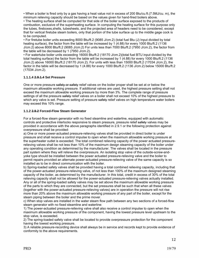
• When a boiler is fired only by a gas having a heat value not in excess of 200 Btu/cu.ft.(7.5MJ/cu. m), the minimum relieving capacity should be based on the values given for hand-fired boilers above. • The heating surface shall be computed for that side of the boiler surface exposed to the products of combustion, exclusive of the superheating surface. In computing the heating surface for this purpose only the tubes, fireboxes,shells, tubesheets, and the projected area of headers need to be considered, except that for vertical firetube steam boilers, only that portion of the tube surface up to the middle gage cock is to be computed. • For firetube boiler units exceeding 8000 Btu/ft.2 (9085 J/cm.2) (total fuel Btu (J) Input divided by total heating surface), the factor from the table will be increased by 1 (4.88) for every 1000 Btu/ft.2 (1136 J/cm.2) above 8000 Btu/ft.2 (9085 J/cm.2) For units less than 7000 Btu/ft.2 (7950 J/cm.2), the factor from the table will be decreased by 1 (7950 J/cm.2). • For watertube boiler units exceeding 16000 Btu/ft.2 (18170 J/cm.2)(total fuel BTU input divided by the total heating surface) the factor from the table will be increased by 1 (4.88) for every 1000 Btu/ft.2 (1136 J/cm.2) above 16000 Btu/ft.2 (18170 J/cm.2). For units with less than 15000 Btu/ft.2 (17034 J/cm.2), the factor in the table will be decreased by 1 (4.88) for every 1000 Btu/ft.2 (1136 J/cm.2) below 15000 Btu/ft.2 (17034 J/cm.2). 1.1.1.4 2.9.1.4 Set Pressure One or more pressure safety or safety relief valves on the boiler proper shall be set at or below the maximum allowable working pressure. If additional valves are used, the highest pressure setting shall not exceed the maximum allowable working pressure by more than 3%. The complete range of pressure settings of all the pressure safety relief valves on a boiler shall not exceed 10% of the highest pressure to which any valve is set. Pressure setting of pressure safety relief valves on high temperature water boilers may exceed this 10% range. 1.1.2 2.9.2 Forced-Flow Steam Generator For a forced-flow steam generator with no fixed steamline and waterline, equipped with automatic controls and protective interlocks responsive to steam pressure, pressure relief safety valves may be provided in accordance with the above paragraphs identified in 2.9.1 or the following protection against overpressure shall be provided: a) One or more power-actuated pressure-relieving valves shall be provided in direct boiler is under pressure and shall receive a control impulse to open when the maximum allowable working pressure at the superheater outlet is exceeded. The total combined relieving capacity of the power actuated pressure-relieving valves shall be not less than 10% of the maximum design steaming capacity of the boiler under any operating condition as determined by the manufacturer. The valves shall be located in the pressure part system where they will relieve the overpressure. An isolating stop valve of the outside-screw-and-yoke type should be installed between the power actuated pressure-relieving valve and the boiler to permit repairs provided an alternate power-actuated pressure-relieving valve of the same capacity is so installed as to be in direct communication with the boiler. b) Spring-loaded safety valves shall be provided having a total combined relieving capacity, including that of the power-actuated pressure-relieving valve, of not less than 100% of the maximum designed steaming capacity of the boiler, as determined by the manufacturer. In this total, credit in excess of 30% of the total relieving capacity shall not be allowed for the power-actuated pressure-relieving valves actually installed. Any or all of the spring-loaded safety valves may be set above the maximum allowable working pressure of the parts to which they are connected, but the set pressures shall be such that when all these valves (together with the power-actuated pressure-relieving valves) are in operation the pressure will not rise more than 20% above the maximum allowable working pressure of any part of the boiler, except for the steam piping between the boiler and the prime mover. c) When stop valves are installed in the water steam flow path between any two sections of a forced-flow steam generator with no fixed steamline and waterline: 1) The power-actuated pressure-relieving valve shall also receive a control impulse to open when the maximum allowable working pressure of the component, having the lowest pressure level upstream to the stop valve, is exceeded. 2) The spring-loaded safety valve shall be located to provide overpressure protection for the component having the lowest working pressure. 3) A reliable pressure-recording device shall always be in service and records kept to provide evidence of conformity to the above requirements.
PRD 19/79

13
1.1.3 2.9.3 Superheaters a) Every attached superheater shall have one or more safety valves. The location shall be suitable for the service intended and shall provide the overpressure protection required. The pressure drop upstream of each safety valve shall be considered in determining the set pressure and relieving capacity of that valve. If the superheater outlet header has a full, free steam passage from end to end and is so constructed that steam is supplied to it at practically equal intervals throughout its length so that there is a uniform flow of steam through the superheater tubes and the header, the safety valve or valves may be located anywhere in the length of header. b) The pressure-relieving capacity of the safety valve or valves on an attached superheater shall be included in determining the number and size of the safety valves for the boiler provided there are no intervening valves between the superheater safety valve and the boiler and the discharge capacity of the pressure safety relief valve or valves, on the boiler, as distinct from the superheater, is at least 75% of the aggregate capacity required. c) Every independently fired superheater that may be shut off from the boiler and permit the superheater to become a fired pressure vessel shall have one or more safety valves having a discharge capacity equal to six pounds of steam per hr/sq. ft. (29 kg per hr per sq. m) of superheater surface measured on the side exposed to the hot gases. d) Every safety valve used on a superheater discharging superheated steam at a temperature over 450°F (230°C) shall have a casing, including the base, body, bonnet, and spindle constructed of steel, steel alloy, or equivalent heat-resistant material. The valve shall have a flanged inlet connection or a welding-end inlet connection. The seat and disk shall be constructed of suitable heat-erosive and corrosive-resistant material, and the spring fully exposed outside of the valve casing so that it is protected from contact with the escaping steam. 1.1.4 2.9.4 ECONOMIZERS An economizer that may not be isolated from a boiler does not require a pressure safety relief valve. Economizers that may be isolated from a boiler or other heat transfer device, allowing the economizer to become a fired pressure vessel, shall have a minimum of one pressure relief valve. Discharge capacity, rated in lbs/hr (kg/hr), of the pressure safety relief valve or valves shall be calculated from the maximum expected heat absorption rate in Btu/hr (Joules/hr) of the economizer, and will be determined from manufacturer data, divided by 1000. The pressure relief valve shall be located as close as possible to the economizer outlet. 1.1.5 2.9.5 Pressure-Reducing Valves a) Where pressure-reducing valves are used, one or more pressure safety or safety relief valves shall be installed on the low pressure side of the reducing valve in those installations where the piping or equipment on the low pressure side does not meet the requirements for the steam supply piping. b) The pressure safety or safety relief valves shall be located as close as possible to the pressure reducing valve. c) Capacity of the pressure safety or safety relief valves shall not be less than the total amount of steam that can pass from the high pressure side to the low pressure side and be such that the pressure rating of the lower pressure piping or equipment shall not be exceeded. d) The use of hand-controlled bypasses around reducing valves is permissible. The bypass around a reducing valve may not be greater in capacity than the reducing valve unless the piping or equipment is adequately protected by pressure safety or safety relief valves or meets the requirements of the high pressure system. e) See Supplement XX1 (check x-ref) for additional information on the calculation of the required capacity of pressure relief valves installed after pressure-reducing valves. 1.1.6 2.9.6 Installation Mounting and Discharge Requirements a) Every boiler shall have outlet connections for the pressure relief valve, or valves, independent of any other outside steam connection, the area of opening shall be at least equal to the aggregate areas of inlet connections of all of the attached pressure relief valves. An internal collecting pipe, splash plate, or pan should be used, provided the total area for inlet of steam thereto is not less than twice the aggregate areas of the inlet connections of the attached pressure relief valves. The holes in such collecting pipes shall be at least 1/4 in. (6 mm) in diameter, and the least dimension in any other form of
PRD 20/79

14
opening for inlet of steam shall be 1/4 in. (6 mm). If pressure relief valves are attached to a separate steam drum or dome, the opening between the boiler proper and the steam drum or dome shall be not less than 10 times the total area of the safety valve inlet. b) Every pressure relief valve shall be connected so as to stand in an upright position with spindle vertical. c) The opening or connection between the boiler and the pressure relief valve shall have at least the area of the valve inlet. No valve of any description should be placed between the pressure relief valves and the boiler, nor on the discharge pipe between the pressure relief valves and the atmosphere. When a discharge pipe is used, the cross-sectional area shall not be less than the full area of the valve outlet or of the total of the areas of the valve outlets, discharging thereinto and shall be as short and straight as possible and arranged to avoid undue stresses on the valve or valves. d) When two or more safety valves are used on a boiler, they should be mounted either separately or as twin valves made by placing individual valves on Y-bases, or duplex valves having two valves in the same body casing. Twin valves made by placing individual valves on Y-bases or duplex valves having two valves in the same body shall be of equal size. e) When two valves of different sizes are installed mounted singly, the relieving capacity of the smaller valve shall not be less than 50% of that of the larger valve. f) When a boiler is fitted with two or more pressure relief valves on one connection, this connection to the boiler shall have a cross sectional area not less than the combined areas of inlet connections of all the pressure relief valves with which it connects. g) All pressure relief valves shall be piped to a safe point of discharge so located or piped as to be carried clear from running boards or platforms. Ample provision for gravity drain shall be made in the discharge pipe at or near each pressure relief valve, and where water or condensation may collect. Each valve shall have an open gravity drain through the casing below the level of the valve seat. For iron- and steel bodied valves exceeding NPS 2 (DN 50), the drain hole shall be tapped not less than NPS 3/8 (DN 10). h) Discharge piping from pressure relief valves on high temperature water boilers shall have adequate provisions for water drainage as well as steam venting. i) If a muffler is used on a pressure relief valve, it shall have sufficient outlet area to prevent back pressure from interfering with the proper operation and discharge capacity of the valve. The muffler plates or other devices shall be so constructed as to avoid a possibility of restriction of the steam passages due to deposits. Mufflers shall not be used on high temperature water boiler pressure relief valves. 1.1.6.1 2.3.1 SUPPORTS, FOUNDATIONS, AND SETTINGS Each boiler pressure relief valve and its associated piping must be safely supported. Design of supports, foundations, and settings shall consider vibration (including seismic where necessary), movement (including thermal movement), and loadings (including reaction forces the weight of water during a hydrostatic test) in accordance with jurisdictional requirements, manufacturer’s recommendations, and/or other industry standards, as applicable. (adapted from Part 1, 2.3.1) 1.1.7 2.2.12.7 Pressure Relief Valves for Thermal Fluid Heaters f. Pressure Relief Valves — Pressure relief valves shall be a closed bonnet design with no manual lift lever. A valve body drain is not required. The pressure relief discharge should be connected to a closed, vented storage tank or blowdown tank with solid piping (no drip pan elbow, or other air gap). When outdoor discharge is used, the following should be considered for discharge piping at the point of discharge: 1. Both thermal and chemical reactions (personnel hazard) 2. Combustible materials (fire hazard) 3. Surface drains (pollution and fire hazard) 4. Loop seal or rain cap on the discharge (keep both air and water out of the system) 5. Drip leg near device (prevent liquid collection) 6. Heat tracing for systems using high freeze point fluids (prevent blockage) ( The following was developed based upon ASME Code Section I, Part PVG) 7. A suitable condenser that will condense all the vapors discharged from the pressure relief valve may be used in lieu of piping the vapors to the atmosphere.
PRD 21/79

15
8. In order to minimize the loss by leakage of material through the pressure relief valve, a rupture disk may be installed between the pressure relief valve and the vaporizer, provided the following requirements are met. 8.1 The cross‐sectional area of the connection to a vaporizer shall be not less than the required relief area of the rupture disk. 8.2 The maximum pressure of the range for which the disk is designed to rupture does not exceed the opening pressure for which the pressure relief valve is set or the maximum allowable working pressure of the vessel. 8.3 The opening provided through the rupture disk, after breakage, is sufficient to permit a flow equal to the capacity of the attached valve, and there is no chance of interference with the proper functioning of the valve, but in no case shall this area be less than the inlet area of the valve. 8.4 The space between a rupture disk and the valve should be provided with a pressure gage, try cock, free vent, or a suitable telltale indicator. This arrangement permits the detection of disk rupture or leakage. 8.5 Pressure relief valve discharge capacity shall be determined from the following equation: W = CKAP √M/T Where A = discharge area of pressure relief valve C = constant for vapor that is a function of the ratio of Specific Heats k = cp/cv . Note: Where k is not known, k = 1.001. K = coefficient of discharge for the valve design M = molecular weight P = (set pressure × 1.03) + Atmosphere Pressure T = absolute temperature at inlet, °F + 460 (°C + 273) W = flow of vapor The required minimum pressure relief valve relieving capacity shall be determined from the following equation: W= C x H x 0.75/h where C = maximum total weight or volume of fuel burned per hour, lb (kg) or ft3 (m3) H = heat of combustion of fuel, Btu/lb (J/kg) or Btu/ft3 (J/m3)
h = latent heat of heat transfer fluid at relieving pressure, Btu/lb (J/kg) W = weight of organic fluid vapor generated per hour The sum of the pressure relief valve capacities marked on the valves shall be equal to or greater than W. 1.2 3.9 Pressure Relief Valves for Steam Heating Boilers, Hot-Water heating boilers, Hot water supply Boilers and Potable Hot Water Heaters See PART 1, par. 3.2 for the scope of pressure retaining items covered by these requirements. 1.2.1 3.9.1 Pressure Relief Safety Valve Requirements — general The following general requirements pertain to the installation of mounting, and connecting pressure relief safety valves on heating boilers. 1.2.1.1 3.9.1.1 Installation of Mounting Pressure Relief Safety and Safety Relief Valves for Steam Heating, Hot-Water Heating, and Hot-Water Supply Boilers 1.2.1.1.1 3.9.1.1.1 Permissible Installation Mounting Safety valves and safety relief valves shall be located at the top side of the boiler. The top side of the boiler shall mean the highest practicable part of the boiler proper but in no case shall the safety valves be located below the normal operating level and in no case shall the safety relief valve be located below the lowest permissible water level. They shall be connected directly to a tapped or flanged opening in the boiler, to a fitting connected to the boiler by a short nipple, to a Y-base, or to a valveless header connecting steam or water outlets on the
PRD 22/79

16
same boiler. Coil or header type boilers shall have the safety valve or safety relief valve located on the steam or hot water outlet end. Safety valves and safety relief valves shall be installed with their spindles vertical. The opening or connection between the boiler and any safety valve or safety relief valve shall have at least the area of the valve inlet. 1.2.1.1.2 3.9.1.1.2 Requirements for Common Connections for Two or More Valves a) When a boiler is fitted with two or more safety valves on one connection, this connection shall have a cross-sectional area not less than the combined areas of inlet connections of all the safety valves with which it connects. b) When a Y-base is used, the inlet area shall be not less than the combined outlet areas. When the size of the boiler requires a safety valve or safety relief valve larger than NPS-4 (DN100), two or more valves having the required combined capacity shall be used. When two or more valves are used on a boiler, they may be single, directly attached, or installed mounted on a Y-base. 1.2.1.2 3.9.1.2 Threaded Connections A threaded connection may be used for attaching a valve. 1.2.1.3 3.9.1.3 Prohibited Installations Mountings Pressure relief Safety and safety relief valves shall not be connected to an internal pipe in the boiler. 1.2.1.4 3.9.1.4 Use of Shutoff Valves Prohibited No shutoff valve of any description shall be placed between the safety or safety relief valve and the boiler or on discharge pipes between such valves and the atmosphere. 1.2.1.5 3.9.1.5 Pressure Relief Safety and Safety Relief Valve Discharge Piping a) A discharge pipe shall be used. Its internal cross-sectional area shall be not less than the full area of the valve outlet or of the total of the valve outlets discharging thereinto, and shall be as short and straight as possible and so arranged as to avoid undue stress on the valve or valves. A union may be installed in the discharge piping close to the valve outlet. When an elbow is placed on a safety or a safety relief valve discharge pipe, it shall be located close to the valve outlet downstream of the union to minimize reaction moment stress. b) The discharge from safety or safety relief valves shall be so arranged that there will be no danger of scalding attendants. The safety or safety relief valve discharge shall be piped away from the boiler to a safe point of discharge, and there shall be provisions made for properly draining the piping. The size and arrangement of discharge piping shall be such that any pressure that may exist or develop will not reduce the relieving capacity of the relieving devices below that required to protect the boiler. 1.2.1.6 3.9.1.6 Temperature and Pressure Safety Relief Valves Hot-water heating or supply boilers limited to a water temperature of 210°F (99°C) may have one or more National Board capacity certified temperature and pressure safety relief valves installed. The requirements of 3.9.1.1 through 3.9.1.5 shall be met, except as follows: a) A Y-type fitting shall not be used. b) If additional valves are used, they shall be temperature and pressure safety relief valves. c) When the temperature and pressure safety relief valve is installed mounted directly on the boiler with no more than 4 in. (100 mm) maximum interconnecting piping, the valve may should be installed in the horizontal position with the outlet pointed down. 1.2.2 3.9.2 Safety Valve Requirements for Steam Heating Boilers a) Safety valves are to be manufactured in accordance with a national or international standard. b) Each steam boiler shall have one or more National Board capacity certified safety valves of the spring pop type adjusted and sealed to discharge at a pressure not to exceed 15 psig (100 kPa).
PRD 23/79

17
c) No safety valve for a steam boiler shall be smaller than NPS 1/2 (DN 15). No safety valve shall be larger than NPS 4 (DN 100). The inlet opening shall have an inside diameter equal to, or greater than, the seat diameter. d) The minimum valve capacity in pounds (kilograms) per hour shall be the greater of that determined by dividing the maximum Btu (Watts) output at the boiler nozzle obtained by the firing of any fuel for which the unit is installed by 1000 Btu/lb (645 W/hr/kg), or shall be determined on the basis of the pounds (kilograms) of steam generated per hour per square foot (square meter) of boiler heating surface as given in Table 3.9.2. For cast-iron boilers, the minimum valve capacity shall be determined by the maximum output method. In many cases a greater relieving capacity of valves will have to be provided than the minimum specified by these rules. In every case, the requirement of 3.9.2(e) shall be met. e) The safety valve capacity for each steam boiler shall be such that with the fuel burning equipment installed, and operated at maximum capacity, the pressure cannot rise more than 5 psig (34 kPa) above the maximum allowable working pressure. f) When operating conditions are changed, or additional boiler heating surface is installed, the valve capacity shall be increased, if necessary, to meet the new conditions and be in accordance with 3.9.2(e). The additional valves required, on account of changed conditions, may be installed on the outlet piping provided there is no intervening valve. 1.2.3 3.9.3 Safety Relief Valve Requirements for Hot Water Heating or Hot Water Supply Boilers a) Safety relief valves are to be manufactured in accordance with a national or international standard. b) Each hot-water heating or hot-water supply boiler shall have at least one National Board capacity certified safety relief valve, of the automatic reseating type set to relieve at or below the maximum allowable working pressure of the boiler. c) Hot-water heating or hot-water supply boilers limited to a water temperature not in excess of 210°F (99°C) may have, in lieu of the valve(s) specified in (b) above, one or more National Board capacity certified temperature and pressure safety relief valves of the automatic reseating type set to relieve at or below the maximum allowable working pressure of the boiler. d) When more than one safety relief valve is used on either hot-water heating or hot water supply boilers, the additional valves shall be National Board capacity certified and may have a set pressure within a range not to exceed 6 psig (40 kPa) above the maximum allowable working pressure of the boiler up to and including 60 psig (414kPa), and 5% for those having a maximum allowable working pressure exceeding 60 psig (413 kPa). e) No safety relief valve shall be smaller than NPS 3/4 (DN 20) nor larger than NPS 4 (DN 100), except that boilers having a heat input not greater than 15,000 Btu/hr (4.4kW) should be equipped with a rated safety relief valve of NPS 1/2 (DN 15). f) The required relieving capacity, in pounds per hour (kg/hr), of the pressure relieving device or devices on a boiler shall be the greater of that determined by dividing the maximum output in Btu (Watts) at the boiler nozzle obtained by the firing of any fuel for which the unit is installed by 1000 Btu/lb (645 w/kg), or shall be determined on the basis of pounds (kilograms) of steam generated per hour per square foot (square meter) of boiler heating surface as given in Table 3.9.2. For cast-iron boilers, the minimum valve capacity shall be determined by the maximum output method. In many cases a greater relieving capacity of valves will have to be provided than the minimum specified by these rules. In every case, the requirements of 3.9.3(h) shall be met. When operating conditions are changed, or additional boiler heating surface is installed, the valve capacity shall be increased, if necessary, to meet the new conditions and shall be in accordance with 3.9.3(h). The additional valves required, on account of changed conditions, may be installed on the outlet piping provided there is no intervening valve. h) Safety relief valve capacity for each boiler with a single safety relief valve shall be such that, with the fuel burning equipment installed and operated at maximum capacity, the pressure cannot rise more than 10% above the maximum allowable working pressure. When more than one safety relief valve is used, the over pressure shall be limited to 10% above the set pressure of the highest set valve allowed by 3.9.3(b). 1.2.4 3.9.4 Safety Relief Valve Requirements for Potable Water Heaters a) Each water heater shall have at least one National Board capacity certified temperature and pressure safety relief valve. No safety relief valve shall be smaller than NPS 3/4 (DN 20). b) The pressure setting shall be less than or equal to the maximum allowable working pressure of the water heater. However, if any of the other components in the hot-water supply system (such as valves,
PRD 24/79

18
pumps, expansion or storage tanks, or piping) have a lesser working pressure rating than the water heater, the pressure setting for the safety relief valve(s) shall be based upon the component with the lowest maximum allowable working pressure rating. If more than one safety relief valve is used, the additional valve(s) may be set within a range not to exceed 10% over the set pressure of the first valve. c) The required relieving capacity in Btu/hr (W) of the safety relief valve shall not be less than the maximum allowable input unless the water heater is marked with the rated burner input capacity of the water heater on the casing in a readily visible location, in which case the rated burner input capacity may be used as a basis for sizing the safety relief valves. The relieving capacity for electric water heaters shall be 3500 Btu/hr (1.0 kW) per kW of input. In every case, the following requirements shall be met. Safety relief valve capacity for each water heater shall be such that with the fuel burning equipment installed and operating at maximum capacity, the pressure cannot rise more than 10% above the maximum allowable working pressure. d) If operating conditions are changed or additional heating surface is installed, the safety relief valve capacity shall be increased, if necessary, to meet the new conditions and shall be in accordance with the above provisions. In no case shall the increased input capacity exceed the maximum allowable input capacity. The additional valves required, on account of changed conditions, may be installed on the outlet piping providing there is no intervening valve. 1.2.4.1 3.9.4.1 Installation Safety relief valves shall be installed by either the installer or the manufacturer before a water heater is placed in operation. 1.2.4.2 3.9.4.2 Permissible Installations Mountings Safety relief valves shall be connected directly to a tapped or flanged opening in the top of the water heater, to a fitting connected to the water heater by a short nipple, to a Y-base, or to a valveless header connecting water outlets on the same heater. Safety relief valves shall be installed with their spindles upright and vertical with no horizontal connecting pipe, except that, when the safety relief valve is installed mounted directly on the water heater vessel with no more than 4 in. (100 mm) maximum interconnecting piping, the valve may be installed in the horizontal position with the outlet pointed down. The center line of the safety relief valve connection shall be no lower than 4 in. (100 mm) from the top of the shell. No piping or fitting used to install mount the safety valve shall be of nominal pipe size less than that of the valve inlet. 1.2.4.3 3.9.4.3 Requirements for Common Connection for Two or More Valves a) When a potable water heater is fitted with two or more safety relief valves on one connection, this connection shall have a cross sectional area not less than the combined areas of inlet connections of all the safety release valves with which it connects. b) When a Y-base is used, the inlet area shall be not less than the combined outlet areas. c) When the size of the water heater requires a safety relief valve larger than NPS 4 (DN 100) two or more valves having the required combined capacity shall be used. When two or more valves are used on a water heater, they may be single, directly attached, or installed mounted on a Y-base. 1.2.4.4 3.9.4.4 Threaded Connections A threaded connection may be used for attaching a pressure relief valve. 1.2.4.5 3.9.4.5 Prohibited Installations Mountings Pressure Safety relief valves shall not be connected to an internal pipe in the water heater or a cold water feed line connected to the water heater. 1.2.4.6 3.9.4.6 Use of Shutoff Valves Prohibited No shutoff valve of any description shall be placed between the safety relief valve and the water heater or on discharge pipes between such valves and the atmosphere. 1.2.4.7 3.9.4.7 Safety Relief Valve Discharge Piping
PRD 25/79

19
a) When a discharge pipe is used, its internal cross-sectional area shall be not less than the full area of the valve outlet or of the total of the valve outlets discharging thereinto, and shall be as short and straight as possible and so arranged as to avoid undue stress on the valve or valves. When an elbow is placed on a safety relief discharge pipe, it shall be located close to the valve outlet. b) The discharge from safety relief valves shall be so arranged that there will be no danger of scalding attendants. When the safety relief valve discharge is piped away from the water heater to the point of discharge, there shall be provisions for properly draining the piping and valve body. The size and arrangement of discharge piping shall be such that any pressure that may exist or develop will not reduce the relieving capacity of the relieving devices below that required to protect the water heater. 1.2.5 3.9.5 Pressure Relief Safety and Safety Relief Valves for Tanks and Heat Exchangers 1.2.5.1 3.9.5.1 Steam to Hot-Water Supply When a hot-water supply is heated indirectly by steam in a coil or pipe within the service limitations set forth in Part 1, paragraph 3.2, Definitions, the pressure of the steam used shall not exceed the safe working pressure of the hot water tank, and a safety relief valve at least NPS 1 (DN 25), set to relieve at or below the maximum allowable working pressure of the tank, shall be applied on the tank. 1.2.5.2 3.9.5.2 High Temperature Water to Water Heat Exchanger When high temperature water is circulated through the coils or tubes of a heat exchanger to warm water for space heating or hot-water supply, within the service limitations set forth in Part 1, paragraph 3.2, Definitions, the heat exchanger shall be equipped with one or more National Board capacity certified pressure safety relief valves set to relieve at or below the maximum allowable working pressure of the heat exchanger, and of sufficient rated capacity to prevent the heat exchanger pressure from rising more than 10% above the maximum allowable working pressure of the vessel. 1.2.5.3 3.9.5.3 High Temperature Water to Steam Heat Exchanger When high temperature water is circulated through the coils or tubes of a heat exchanger to generate low pressure steam, within the service limitations set forth in Part 1, paragraph 3.2, Definitions, the heat exchanger shall be equipped with one or more National Board capacity certified pressure relief safety valves set to relieve at a pressure not to exceed 15 psig (100 kPa), and of sufficient rated capacity to prevent the heat exchanger pressure from rising more than 5 psig (34 kPa) above the maximum allowable working pressure of the vessel. For heat exchangers requiring steam pressures greater than 15 psig (100 kPa), refer to Part 1, Section 2 or Section 4 of this Part. 1.3 Pressure Vessel Pressure Relief Devices See Part 1, par. 4.1 for the scope of pressure vessels covered by these requirements.. All pressure vessels shall be protected by pressure relief devices in accordance with the following requirements. 1.3.1 4.5.1 Device Requirements a) Pressure relief devices are to be manufactured in accordance with a national or international standard and shall be certified for capacity (or resistance to flow for rupture disk devices) by the National Board. b) Dead weight or weighted lever pressure relief valves shall not be used. c) An unfired steam boiler shall be equipped with pressure relief valves as required in Section 2 of this Part. (See 2.9). d) Pressure relief devices shall be selected (i.e., material, pressure, etc.) and installed such that their proper functioning will not be hindered by the nature of the vessel’s contents. 1.3.2 4.5.2 Number of Devices
PRD 26/79

20
At least one device shall be provided for protection of a pressure vessel. Pressure vessels with multiple chambers with different maximum allowable working pressures shall have a pressure relief device to protect each chamber under the most severe coincident conditions. 1.3.3 4.5.3 Location a) The pressure relief device shall be installed directly on the pressure vessel, unless the source of pressure is external to the vessel and is under such positive control that the pressure cannot exceed the maximum overpressure permitted by the original code of construction and the pressure relief device cannot be isolated from the vessel, except as permitted by 4.5.6 e) 2) (CHECK PAR. X-REF). b) Pressure relief devices intended for use in compressible fluid service shall be connected to the vessel in the vapor space above any contained liquid or in the piping system connected to the vapor space. c) Pressure relief devices intended for use in liquid service shall be connected below the normal liquid line. The liquid level during upset conditions shall be considered. 1.3.4 4.5.4 Capacity a) The pressure relief device(s) shall have sufficient capacity to ensure that the pressure vessel is not exposed to pressure greater than that specified in the original code of construction. b) If an additional hazard can be created by exposure of a pressure vessel to fire or other unexpected source of external heat, supplemental pressure relief devices shall be installed to provide any additional capacity that should be required. c) Vessels connected together by a system of piping not containing valves that can isolate any pressure vessel may should be considered as one unit when determining capacity requirements. d) Heat exchangers and similar vessels shall be protected with a pressure relief device of sufficient capacity to avoid overpressure in case of internal failure. e) When a non-reclosing device is installed between a pressure relief valve and the pressure vessel, the reduction in capacity due to installation of the non-reclosing device shall be determined in accordance with the code of construction by use of a National Board certified Combination Capacity Factor (CCF). For rupture disks, if a certified combination capacity factor is not available, the capacity of the pressure relief valve shall be multiplied by 0.9 and this value used as the capacity of the combination installation. f) The owner shall document the basis for selection of the pressure relief devices used, including capacity, and have such calculations available for review by the Jurisdiction. 1.3.5 4.5.5 Set Pressure a) When a single pressure relief device is used, the set pressure marked on the device shall not exceed the maximum allowable working pressure. b) When more than one pressure relief device is provided to obtain the required capacity, only one pressure relief device set pressure needs to be at the maximum allowable working pressure. The set pressures of the additional pressure relief devices shall be such that the pressure cannot exceed the overpressure permitted by the code of construction. 1.3.6 4.5.6 Installation and Discharge Piping Requirements a) The opening through all pipe and fittings between a pressure vessel and its pressure relief device shall have at least the area of the pressure relief device inlet. The characteristics of this upstream system shall be such that the pressure drop will not reduce the relieving capacity below that required or adversely affect the proper operation of the pressure relief device. b) A non-reclosing device installed between a pressure vessel and a pressure relief valve shall meet the requirements of 4.5.6(a) (check cross reference here). c) The opening in the pressure vessel wall shall be designed to provide unobstructed flow between the vessel and its pressure relief device. d) When two or more required pressure relief devices are placed on one connection, the inlet cross-sectional area of this connection shall be sized either to avoid restricting flow to the pressure relief devices or made at least equal to the combined inlet areas of the pressure relief devices connected to it. The flow characteristics of the upstream system shall satisfy the requirements of 4.5.6(a). e) There shall be no intervening stop valves between the vessel and its pressure relief device(s), or between the pressure relief device(s) and the point of discharge, except under the following conditions:
PRD 27/79
21
1) When these stop valves are so constructed or positively controlled that the closing of the maximum number of block valves at one time will not reduce the pressure relieving capacity below the required relieving capacity; or, 2) Upon specific acceptance of the Jurisdiction, when necessary for the continuous operation of processing equipment of such a complex nature that shutdown of any part is not feasible, a full area stop valve between a pressure vessel and its pressure relief device should be provided for inspection and repair purposes only. This stop valve shall be arranged so that it can be locked or sealed open, and it shall not be closed except by an authorized person who shall remain stationed there during that period of operation while the valve remains closed. The valve shall be locked or sealed in the open position before the authorized person leaves the station. 3) A full area stop valve should also be placed on the discharge side of a pressure relief device when its discharge is connected to a common header for pressure relief devices to prevent discharges from these other devices from flowing back to the first device during inspection and repair. This stop valve shall be arranged so that it can be locked or sealed open, and it shall not be closed except by an authorized person who shall remain stationed there during that period of operation while the valve remains closed. The valve shall be locked and sealed in the open position before the authorized person leaves the station. This valve shall only be used when a stop valve on the inlet side of the pressure relief device is first closed. 4) A pressure vessel in a system where the pressure originates from an outside source should have a stop valve between the vessel and the pressure relief device, and this valve need not be sealed open, provided it also closes off that vessel from the source of the pressure. 5) Pressure vessels designed for human occupancy (such as decompression or hyperbaric chambers) shall be provided with a quick opening stop valve between the pressure vessel and its pressure relief valve. The stop valve shall be normally sealed open with a frangible seal and be readily accessible to the pressure relief attendant. f) Pressure relief device discharges shall be arranged such that they are not a hazard to personnel or other equipment and, when necessary, lead to a safe location for disposal of fluids being relieved. g) Discharge lines from pressure relief devices shall be designed to facilitate drainage or be fitted with drains to prevent liquid from collecting in the discharge side of a pressure relief device. The size of discharge lines shall be such that any pressure that may exist or develop will not reduce the relieving capacity of the pressure relief device or adversely affect the operation of the pressure relief device. h) Pressure relief devices shall be installed so they are readily accessible for inspection, repair, or replacement. i) Pressure vessel pressure relief devices and discharge piping shall be safely support. Design of supports, foundations, and settings shall consider vibration (including seismic where necessary), movement (including thermal movement), and loadings (including reaction forces during device operation the weight of water during a hydrostatic test) in accordance with jurisdictional requirements, manufacturer’s recommendations, and/or other industry standards, as applicable. (Based upon Part 1, 4.3.1.) 1.4 5.3 Piping System Pressure Relief Devices See NBIC Part 1, par. X.x for the piping systems covered under this section. When required by the original code of construction, piping shall be protected by pressure relief devices in accordance with the following requirements. 1.4.1 5.3.1 Device Requirements a) Pressure relief devices are to be manufactured in accordance with a national or international standard and be certified for capacity (or resistance to flow for rupture disc devices) by the National Board. 1) In certain cases piping standards permit the use of regulators, which may include integral pressure relief valves to limit the pressure in a piping system. In this case, capacity certification of the pressure relief valve is not required. b) Dead weight or weighted lever pressure relief devices shall not be used. c) Pressure relief devices shall be selected (i.e., material, pressure, etc.) and installed such that their proper functioning will not be hindered by the nature of the piping system’s contents. 1.4.2 5.3.2 Number of Devices
PRD 28/79
22
At least one pressure relief device shall be provided for protection of a piping system. A pressure relief device installed on a pressure vessel or other component connected to the piping system should be used to meet this requirement. Portions of piping systems with different maximum allowable working pressures shall have a pressure relief device to protect each portion separately. 1.4.3 5.3.3 Location Pressure relief devices, except those covered by Sections 1.1 through 1.3 2 and 3 of this Part, may be installed at any location in the system provided the pressure in any portion of the system cannot exceed the maximum overpressure permitted by the original code of construction. Pressure drop to the pressure relief device under flowing conditions shall be considered when determining pressure relief device location. The pressure-relief device shall not be isolated from the piping system except as permitted by 5.3.6 e). check cross reference 1.4.4 5.3.4 Capacity a) The pressure relief device(s) shall have sufficient capacity to ensure that the piping is not exposed to pressures greater than that specified in the original code of construction. b) When a non-reclosing device is installed between a pressure relief valve and the pipe, the reduction in capacity due to installation of the non-reclosing device shall be determined in accordance with the code of construction by use of a National Board certified Combination Capacity Factor (CCF). For rupture disks, if a certified combination capacity factor is not available, the capacity of the pressure relief valve shall be multiplied by 0.9 and this value used as the capacity of the combination installation. c) The owner shall document the basis for selection of the pressure relief devices used, including capacity, and have such calculations available for review by the Jurisdiction, when required. 1.4.5 5.3.5 Set Pressure a) When a single pressure relief device is used, the set pressure marked on the device shall not exceed the maximum allowable working pressure, except when allowed by the original code of construction. b) When more than one pressure relief device is provided to obtain the required capacity, only one pressure relief device set pressure needs to be at the maximum allowable working pressure. The set pressures of the additional pressure relief devices shall be such that the pressure cannot exceed the overpressure permitted by the code of construction. 1.4.6 5.3.6 inlet and Discharge Piping Requirements a) The opening through all pipes and fittings between a piping system and its pressure relief device shall have at least the area of the pressure relief device inlet. The characteristics of this upstream system shall be such that the pressure drop will not reduce the relieving capacity below that required or adversely affect the operation of the pressure relief device. b) A non-reclosing device installed between a piping system and a pressure relief valve shall meet the requirements of 5.3.6(a). check cross reference c) The opening in the pipe shall be designed to provide unobstructed flow between the pipe and its pressure relief device. d) When two or more required pressure relief devices are placed on the connection, the inlet cross-sectional area of this connection shall be sized either to avoid restricting flow to the pressure relief devices or made at least equal to the combined inlet areas of the pressure relief devices connected to it. The flow characteristics of the upstream system shall satisfy the requirements of 5.3.6(a). e) There shall be no intervening stop valves between the piping system and its pressure relief device(s), or between the pressure relief device(s) and the point of discharge except under the following conditions: 1) When these stop valves are so constructed or positively controlled that the closing of the maximum number of block valves at one time will not reduce the pressure relieving capacity below the required relieving capacity; or,
PRD 29/79

23
2) Upon specific acceptance of the Jurisdiction, when necessary for the continuous operation of processing equipment of such a complex nature that shutdown of any part is not feasible, a full area stop valve between a piping system and its pressure relief device should may be provided for inspection and repair purposes only. This stop valve shall be arranged so that it can be locked or sealed open and it shall not be closed except by an authorized person who shall remain stationed there during that period of operation while the valve remains closed. The valve shall be locked or sealed in the open position before the authorized person leaves the station. 3) A full area stop valve may be placed on the discharge side of a pressure relief device when its discharge is connected to a common header for pressure relief devices to prevent discharges from these other devices from flowing back to the first device during inspection and repair. This stop valve shall be arranged so that it can be locked or sealed open, and it shall not be closed except by an authorized person who shall remain stationed there during that period of operation while the valve remains closed. The valve shall be locked or sealed in the open position before the authorized person leaves the station. This valve shall only be used when a stop valve on the inlet side of the pressure relief device is first closed. 4) A piping system where the pressure originates from an outside source should have a stop valve between the system and the pressure relief device, and this valve need not be sealed open, provided it also closes off that vessel from the source of pressure. f) Pressure relief device discharges shall be arranged such that they are not a hazard to personnel or other equipment and, when necessary, lead to a safe location for disposal of fluids being relieved. g) Discharge lines from pressure relief devices shall be designed to facilitate drainage or be fitted with drains to prevent liquid from collecting in the discharge side of a pressure relief device. The size of discharge lines shall be such that any pressure that may exist or develop will not reduce the relieving capacity of the pressure relief device or adversely affect the operation of the pressure relief device. h) The reaction forces due to discharge of pressure relief devices shall be considered in the design of the inlet and discharge piping. I) Pressure relief devices shall be installed so they are accessible for inspection, repair, or replacement.
PRD 30/79
24
In-Service Inspection (previously in Part 2) 2.0 2.5 In-Service Inspection of Pressure Relief Devices Once a pressure relief device is installed on a piece of pressurized equipment or system, it must be periodically inspected and tested to assure that the pressure relieving function can still be relied upon. The inspection of pressure relief devices is often coordinated with the inspection of the system. See NBIC Part 2 for in service inspection requirements and procedures for other portions of the equipment not discussed below. 2.1 2.5.1 Scope a) The most important appurtenances on any pressurized system are the pressure relief devices provided for overpressure protection of that system. These are devices such as safety valves, safety relief valves, pilot valves, and rupture disks or other nonreclosing devices that are called upon to operate and reduce an overpressure condition. b) These devices are not designed or intended to control the pressure in the system during normal operation. Instead, they are intended to function when normal operating controls fail or abnormal system conditions are encountered. c) Periodic inspection and maintenance of these important safety devices is critical to ensure their continued functioning and to provide assurance that they will be available when called upon to operate. See 2.5.8 (CHECK X-REF) for recommended testing frequency for PRDs. d) Inspection areas of concern include: 1) correct set pressure; (matching of set pressure to MAWP) 2) safety considerations; (is something missing here? Need information on respecting pressure, noise, heat etc) 3) device data; 4) condition of the device; 5) condition of the installation; and 6) testing and operational inspection. 2.1.1 2.5.2 Pressure Relief Device Data a) Nameplate marking or stamping of the device should be compared to stamping on the protected pressure-retaining item. For a single device, the set pressure shall be no higher than the maximum allowable working pressure (MAWP) marked on the protected pressure-retaining item or system. b) If multiple devices are provided, the difference between set pressures shall not exceed that permitted by the original code of construction. The set pressure of additional devices may exceed the MAWP, as permitted by the original Code of Construction. c) Verify nameplate capacity and, if possible, compare to system capacity requirements. d) Check identification on seals and ensure they match nameplates or other identification (repair or reset nameplate) on the valve or device. 2.1.2 2.5.3 Device conditions a) Check for evidence that the valve or device is leaking or not sealing properly. Evidence of leakage through pressure-relief valves may indicate that the system is being operated at a pressure that is too close to the valve’s set pressure. (See Part 2, Supplement 2 8 for guidance on the pressure differential between the pressure relief valve set pressure and system operating pressure.) b) Seals for adjustments shall should be intact and show no evidence of tampering. c) Connecting bolting should be tight and all bolts intact. d) The valve or device should be examined for deposits or material buildup. e) Evidence of rust or corrosion should be checked. f) Check for damaged or misapplied parts. g) If a drain hole is visible, ensure it is not clogged with debris or deposits. h) Check for test gags left in place after pressure testing of the unit.
PRD 31/79

25
i) Bellows valves shall be checked to ensure the bonnet vent is open or piped to a safe location. The vent shall not be plugged since this will cause the valve set pressure to be high if the bellows develops a leak. Leakage noted from the vent indicates the bellows is damaged and will no longer protect the valve from the effects of back pressure. 2.1.3 2.5.4 Installation Condition a) Inspect inlet piping and ensure it meets the requirements of the original Code of Construction. For pressure relief valves, check that the inlet pipe size is not smaller than the device inlet size. b) Inspect discharge piping and ensure it meets the original Code of Construction. Check that the discharge pipe size is not smaller than the device outlet size. c) Check that the valve drain piping is open. d) Check drainage of discharge piping. e) Check that inlet and discharge piping are not binding or placing excessive stress on the valve body, which can lead to distortion of the valve body and leakage or malfunction. f) Check the condition and adequacy of piping supports. Discharge piping should be supported independent of the device itself. g) Check for possible hazards to personnel from the valve discharge or discharge pipe. h) Check that there are no intervening isolation valves between the pressure source and the valve inlet or between the valve outlet and its point of discharge. (Isolation valves may be permitted in some pressure vessel service. See Part 1, 5.3.6 e.), and jurisdictional requirements. Isolation valves are not permitted for power boilers, heating boilers, or water heaters.) i) A change-over valve, which is used to install two pressure relief devices on a single vessel location for the purpose of switching from one device to a spare device, is not considered a block valve if it is arranged such that there is no intermediate position that will isolate both pressure relief devices from the protected system. Change-over valves should be carefully evaluated to ensure they do not have excessive pressure drop that could affect the pressure relief device operation or capacity. These devices are commonly used in pressure vessel service. They may also be used in some boiler applications. It is recommended that the Jurisdiction be contacted to determine their acceptability on boiler applications. 2.1.4 2.5.5 Additional Inspection Requirements Following are additional items that should be considered for the specified types of installations or services. 2.1.4.1 2.5.5.1 BOILERS a) If boilers are piped together with maximum allowable working pressures differing by more than 6%, additional protective devices may be required on the lower pressure units to protect them from overpressure from the higher pressure unit. b) Hot-Water Heating Boilers and Water Heaters 1) These units generally do not use any water treatment and therefore may be more prone to problems with deposits forming that may impair a safety device’s operation. Particular attention should be paid to signs of leakage through valves or buildups of deposits. 2) Hot-water boilers tend to have buildups of corrosion products since the system is closed with little makeup. These products can foul or block the valve inlet. 3) Water heaters will have cleaner water due to continuous makeup. However, these valves usually have a thermal element that will cause the valve to open slightly when the water is heated and the heat is not removed from the system. When this hot water evaporates in the discharge piping, scale calcium deposits may tend to form in the valve inlet and outlet. 2.1.4.2 2.5.5.2 PRESSURE VESSELS AND PIPING Standard practice for overpressure protection devices is to not permit any type of isolation valve either before or after the device. However, some pressure vessel standards permit isolation valves under certain controlled conditions when shutting down the vessel to repair a damaged or leaking valve. If isolation block valves are employed, their use should be carefully controlled by written procedures. Block valves should have provisions to be either car-sealed or locked in an open position when not being used. For ASME Section VIII, Div. 1 pressure vessels, see UG-135, Appendix M, and jurisdictional rules for more information.
PRD 32/79

26
2.1.4.3 2.5.5.3 RUPTURE DISKS a) Rupture disks or other non-reclosing devices may be used as sole relieving devices or in combination with safety relief valves to protect pressure vessels. b) The selection of the correct rupture disk device for the intended service is critical to obtaining acceptable disk performance. Different disk designs are intended for constant pressure, varying pressure, or pulsating pressure. Some designs include features that make them suitable for back pressure and/or internal vacuum in the pressure vessel. c) The margin between the operating pressure and the burst pressure is an important factor in obtaining acceptable performance and service life of the disk. Flat and prebulged solid metal disks are typically used with an operating pressure that is no more than 60% to 70% of the burst pressure. Other designs are available that increase the operating pressure to as much as 90% of the burst pressure. Disks that have been exposed to pressures above the normal operating pressure for which they are designed are subject to fatigue or creep and may fail at unexpectedly low pressures. Disks used in cyclic service are also subject to fatigue and may require a greater operating margin or selection of a device suitable for such service. d) The disk material is also critical to obtaining acceptable service life from the disk. Disks are available in a variety of materials and coatings, and materials that are unaffected by the process fluid should be used. Disks that experience corrosion may fail and open at an unexpectedly low pressure. e) Disk designs must also be properly selected for the fluid state. Some disk types are not suitable for use in liquid service. Some disks may have a different flow resistance when used in liquid service, which may affect the sizing of the disk. f) Information from the rupture disk manufacturer, including catalog data and installation instructions, should be consulted when selecting a disk for a particular service. g) For rupture disks and other non-reclosing devices, the following additional items should be considered during inspections. 1) The rupture disk nameplate information, including stamped burst pressure and coincident temperature, should be checked to ensure it is compatible with the intended service. The coincident temperature on the rupture disk shall be the expected temperature of the disk when the disk is expected to burst and will usually be related to the process temperature, not the temperature on the pressure vessel nameplate. 2) Markings indicating direction of flow should be carefully checked to ensure they are correct. Some rupture disks when installed in the incorrect position may burst well above the stamped pressure. 3) The marked burst pressure for a rupture disk installed at the inlet of a safety relief valve shall be equal to or less than the safety relief valve set pressure. A marked burst pressure of 90% to 100% of the safety relief valve set pressure is recommended. A disk with a non-fragmenting design that cannot affect the safety relief valve shall be used. Note: If the safety relief valve set pressure is less than the vessel MAWP, the marked burst pressure may be higher than the valve set pressure, but no higher than the MAWP. 4) Check that the space between a rupture disk and a safety relief valve is supplied with a pressure gage, try cock, or telltale indicator to indicate signs of leakage through the rupture disk. The safety relief valve shall be inspected and the leaking disk shall be replaced if leakage through the disk is observed. 5) If a rupture disk is used on a valve outlet, the valve design must be of a type not influenced by back pressure due to leakage through the valve. Otherwise, for nontoxic and non-hazardous fluids, the space between the valve and the rupture disk shall be vented or drained to prevent the accumulation of pressure. 6) For rupture disks installed on the valve inlet, the installation should be reviewed to ensure that the combination rules of the original Code of Construction have been applied. A reduction in the valve capacity up to 10% is expected when used in combination with a non-reclosing device. 7) The frequency of inspection for rupture disks and other non-reclosing devices is greatly dependent on the nature of the contents and operation of the system and only general recommendations can be given. Inspection frequency should be based on previous inspection history. If devices have been found to be leaking, defective, or damaged by system contents during inspection, intervals should be shortened until acceptable inspection results are obtained. With this in mind, the inspection frequency guidelines specified in 2.5.8 are suggested for similar services. 8) Rupture disks are often used to isolate pressure relief valves from services where fouling or plugging of the valve inlet occurs. This tendency should be considered in establishing the inspection frequency.
PRD 33/79

27
9) Since these devices are for one time use, a visual inspection is the only inspection that can be performed. Rupture disks that are installed using a specified bolting torque procedure cannot be reused after inspection and must be replaced. 10) It is recommended that all rupture disks be periodically replaced to prevent unintended failure while in service due to deterioration of the device. Rupture disks should be carefully checked for damage prior to installation and handled by the disk edges, if possible. Any damage to the surface of the ruptured disk can affect the burst pressure. 2.5.6 Packaging, Shipping and Transportation of Pressure Relief Devices (moved to Supplement 4 for repair procedures and combined with similar text) 2.1.5 2.5.7 Testing and Operational Inspection of Pressure Relief Devices a) Pressure relief valves must be periodically tested to ensure that they are free to operate and will operate in accordance with the requirements of the original Code of Construction. Testing should include device set or opening pressure, reclosing pressure, where applicable, and seat leakage evaluation. Tolerances specified for these operating requirements in the original Code of Construction shall be used to determine the acceptability of test results. b) Testing may be accomplished by the owner on the unit where the valve is installed or at a qualified test facility. In many cases, testing on the unit may be impractical, especially if the service fluid is hazardous or toxic. Testing on the unit may involve the bypassing of operating controls and should only be performed by qualified individuals under carefully controlled conditions. It is recommended that a written procedure be available to conduct this testing. 1) The Inspector should ensure that calibrated equipment has been used to perform this test and the results should be documented by the owner. 2) If the testing was performed at a test facility, the record of this test should be reviewed to ensure the valve meets the requirements of the original Code of Construction. Valves which have been in toxic, flammable, or other hazardous services shall be carefully decontaminated before being tested. In particular, the closed bonnet of valves in these services may contain fluids that are not easily removed or neutralized. If a test cannot be safely performed, the valve shall be disassembled, cleaned, and decontaminated, repaired, and reset. 3) If a valve has been removed for testing, the inlet and outlet connections should be checked for blockage by product buildup or corrosion. c) Valves may be tested using lift assist devices when testing at full pressure may cause damage to the valve being tested, or it is impractical to test at full pressure due to system design considerations. Lift assist devices apply an auxiliary load to the valve spindle or stem, and using the measured inlet pressure, applied load and other valve data allow the set pressure to be calculated. If a lift assist device is used to determine valve set pressure, the conditions of Part 3, Repairs and Alterations, Section 4.5.3 (need new cross reference here) shall be met. It should be noted that false set pressure readings may be obtained for valves which are leaking excessively or otherwise damaged. d) If valves are not tested on the system using the system fluid, the following test mediums shall be used: 1) High pressure boiler safety valves, high temperature hot-water boiler safety relief valves, low pressure steam heating boilers: steam; 2) Hot-water heating boiler safety relief valves: steam, air, or water; 3) Hot water heater temperature and pressure relief valves: air or water; 4) Air and gas service process safety relief valves: air, nitrogen, or other suitable gas; 5) Liquid service process pressure relief valves: water or other suitable fluid; 6) Process steam service safety relief valves: steam or air with manufacturer’s steam to air correction factor. Note: Valves being tested after a repair must be tested on steam except as permitted by Part 3, Repairs and Alterations, Section 4.5.2 (CHECK X-REF). e) As an alternative to a pressure test, the valve may be checked by the owner for freedom of operation by activating the test or “try” lever (manual check). For high pressure boiler and process valves, this test should be performed only at a pressure greater than 75% of the stamped set pressure of the valve or the lifting device may be damaged. This test will only indicate that the valve is free to operate and does not provide any information on the actual set pressure. All manual checks should be performed with some pressure under the valve in order to flush out debris from the seat that could cause leakage.
PRD 34/79
28
Note: The manual check at 75% or higher is based on lift lever design requirements for ASME Section I and VIII valves. Code design requirements for lifting levers for Section IV valves require that the valve be capable of being lifted without pressure. i) Systems with multiple valves will require the lower set valves to be held closed to permit the higher set valves to be tested. A test clamp or “gag” should be used for this purpose. The spring compression screw shall not be tightened. It is recommended that the test clamps be applied in accordance with the valve manufacturer’s instructions when the valve is at or near the test temperature, and be applied hand tight only to avoid damage to the valve stem or spindle. j) Upon completion of set pressure testing, all pressure relief valve gags shall be removed. 2.1.5.1 CORRECTIVE ACTION f) If a valve is found to be stuck closed, the system should immediately be taken out of service until the condition can be corrected, unless special provisions have been made to operate on a temporary basis (such as additional relief capacity provided by another valve). The owner shall be notified and corrective action such as repairing or replacing the inoperable valve shall be taken. 2.1.5.2 VALVE ADJUSTMENTS g) a) If a set pressure test indicates the valve does not open within the requirements of the original Code of Construction, but otherwise is in acceptable condition, minor adjustments (defined as no more than twice the permitted set pressure tolerance) shall be made by an qualified organization accredited by the National Board to reset the valve to the correct opening pressure. All adjustments shall be resealed with a seal identifying the responsible organization and a tag shall be installed identifying the organization and the date of the adjustment. Qualified organizations are considered to be National Board “VR” stamp holders, or organizations authorized by the Jurisdiction to make adjustments. See Supplement 3 for more information. h) b) If a major adjustment is needed, this may indicate the valve is in need of repair or has damaged or misapplied parts. Its condition should be investigated accordingly. 2.1.6 2.5.8 RECOMMENDED INSPECTION AND TEST FREQUENCIES FOR PRESSURE RELIEF DEVICES a) Power Boilers 1) Pressure less than 400 psig (2.76 MPa): Manual check every 6 months; pressure test annually to verify nameplate set pressure or as determined by operating experience as verified by testing history. 2) Pressure greater than 400 psig (2.76 MPa): Pressure test to verify nameplate set pressure every three years or as determined by operating experience as verified by testing history. 3) Pressure tests should be performed prior to bringing the boiler down for planned internal inspection so needed repairs or adjustments can be made while the boiler is down. b) High-Temperature Hot-Water Boilers Pressure test annually to verify nameplate set pressure or as determined by operating experience as verified by testing history. For safety reasons, removal and testing on a steam test bench is recommended. Such testing will avoid damaging the safety valve by discharge of a steam water mixture, which could occur if the valve is tested in place. C) Organic Fluid Vaporizers Pressure relief valves shall be disconnected from the vaporizer at least once yearly, when they shall be inspected, tested, repaired if necessary, and then replaced on the vaporizer. (From Section I part PVG 12.2) d) Low-Pressure Steam Heating Boilers Manual check quarterly; pressure test annually prior to steam heating season to verify nameplate set pressure. e) Hot-Water Heating Boilers Manual check quarterly; pressure test annually prior to heating season to verify nameplate set pressure.
PRD 35/79

29
Note: The frequencies specified for the testing of pressure relief valves on boilers is primarily based on differences between high pressure boilers that are continuously manned, and lower pressure automatically controlled boilers that are not monitored by a boiler operator at all times. When any boiler experiences an overpressure condition such that the safety or safety relief valves actuate, the valves should be inspected for seat leakage and other damage as soon as possible and any deficiencies corrected. f) Water Heaters Manual check every two months. Due to the relatively low cost of safety valves for this service, it is recommended that a defective valve be replaced with a new valve if a repair or resetting is indicated. g) Pressure Vessels and Piping Frequency of test and inspection of pressure relief devices for pressure vessel and piping service is greatly dependent on the nature of the contents and operation of the system and only general recommendations can be given. Inspection frequency should be based on previous inspection history. If valves are found to be defective or damaged by system contents during inspection, intervals should be shortened until acceptable inspection results are obtained. Where test records and/or inspection history are not available, the following inspection and test frequencies are suggested. (following to be presented as a table) Service Inspection Frequency Steam Annual Air and Clean Dry Gases Every three years Pressure relief valves in combination with rupture disks Every five years Propane, Refrigerant Every five years All Others Per inspection history 2.1.6.1 g) Establishment of Inspection and Test Intervals Where a recommended test frequency is not listed, the valve user and Inspector must determine and agree on a suitable interval for inspection and test. Some items to be considered in making this determination are: 1) Jurisdictional requirements; 2) Records of test data and inspections from similar processes and similar devices in operation at that facility; 3) Recommendations from the device manufacturer. In particular, when the valve includes non-metallic parts such as a diaphragm or soft seat, periodic replacement of those parts may be specified; 4) Operating history of the system. Systems with frequent upsets where a valve has actuated require more frequent inspection; 5) Results of visual inspection of the device and installation conditions. Signs of valve leakage, corrosion or damaged parts all indicate more frequent operational inspections; 6) Installation of a valve in a system with a common discharge header. Valves discharging into a common collection pipe may be affected by the discharge of other valves by the corrosion of parts in the outlet portion of the valve or the buildup of products discharged from those valves; 7) Ability to coordinate with planned system shutdowns. The shutdown of a system for other maintenance or inspection activities is an ideal time for the operational inspection and test of a pressure relief valve; 8) Critical nature of the system. Systems that are critical to plant operation or where the effects of the discharge of fluids from the system are particularly detrimental due to fire hazard, environmental damage, or toxicity concerns all call for more frequent inspection intervals to ensure devices are operating properly; 9) Where the effects of corrosion, blockage by system fluid, or ability of the valve to operate under given service conditions are unknown (such as in a new process or installation), a relatively short inspection interval, not to exceed one year or the first planned shutdown, whichever is shorter, shall be established. At that time the device shall be visually inspected and tested. If unacceptable test results are obtained, the inspection interval shall be reduced by 50% until suitable results are obtained. 2.1.6.2 h) Establishment of Service Intervals 1) The above intervals are guidelines for periodic inspection and testing. Typically if there are no adverse findings, a pressure relief valve would be placed back in service until the next inspection. Any unacceptable conditions that are found by the inspection shall be corrected immediately by repair or
PRD 36/79

30
replacement of the device. Many users will maintain spare pressure relief devices so the process or system is not affected by excessive downtime. 2) Pressure relief valves are mechanical devices that require periodic preventive maintenance even though external inspection and test results indicate acceptable performance. There may be wear on internal parts, galling between sliding surfaces or internal corrosion, and fouling which will not be evident from an external inspection or test. Periodic re-establishment of seating surfaces and the replacement of soft goods such as o-rings and diaphragms are also well advised preventive maintenance activities that can prevent future problems. If the valve is serviced, a complete disassembly, internal inspection, and repair as necessary, such that the valve’s condition and performance are restored to a like new condition, should be done by an organization accredited by the National Board. 3) Service records with test results and findings should be maintained for all overpressure protection devices. A service interval of no more than three inspection intervals or ten years, whichever is less, is recommended to maintain device condition. Results of the internal inspection and maintenance findings can then be used to establish future service intervals.
PRD 37/79

31
REPAIR (previously in Part 3) 3.0 S7.1 REPAIR OF PRESSURE RELIEF DEVICES, SCOPE This section supplement provides general requirements that apply to repairs to pressure relief valves. Repairs may be required because of defects found during periodic inspections, because testing has identified that valve performance does not meet the original code of construction requirements, failure during operation, or for routine preventative maintenance. Since pressure relief devices are provided for safety and the protection of personnel and property, repairs are often regulated by the jurisdiction where the pressure relief device is installed. The jurisdiction should be contacted for their specific requirements. 3.1 S7.2 GENERAL REQUIREMENTS a) Repair of a pressure relief valve is considered to include the disassembly, replacement, re-machining, or cleaning of any critical part, lapping of a seat and disc, reassembly, adjustment, testing, or any other operation that may affect the flow passage, capacity, function, or pressure-retaining integrity. b) Conversions, changes, or adjustments affecting critical parts are also considered repairs. The scope of conversions may include changes in service fluid and changes such as bellows, soft seats, and other changes that may affect Type/Model number provided such changes are recorded on the document as required for a quality system and the repair nameplate. (See 5.9.1 check cross reference). c) The scope of repair activities shall not include changes in ASME Code status. 3.1.1 d) When a repair is being performed under the administrative requirements for National Board Accreditation, a repair shall consist of the following operations as a minimum: 1) Complete disassembly, cleaning, and inspection of parts, repair or replacement of parts found to be defective, reassembly, testing as required by 4.5 (check x-ref), sealing and application of a repair nameplate. When completed, the valve’s condition and performance shall be equivalent to the standards for new valves. 2) The administrative requirements for National Board Accreditation apply only to valves that are stamped with an ASME “V,” “UV,” or “NV” Code symbol or marked with an ASME “HV” symbol and have been capacity certified on the applicable fluid by the National Board. 3.1.2 1.2 Construction Standards for pressure relief devices retaining items d) For pressure relief ving devices the applicable new construction standard for new valves to be used for reference during repairs is the ASME Code. ASME code cases shall be used for repairs when they were used in the original construction of the valve. ASME code cases may be used when they have been accepted for use by the NBIC committee and the Jurisdiction where the pressure-retaining item is installed. 1) For pressure relieving devices the code case number shall be noted on the repair document and, when required by the code case, stamped on the repair nameplate. 2) The Jurisdiction where the pressure retaining item is installed shall be consulted for any unique requirements it may have established. 3.1.3 INSTALLATION OF PRESSURE RELIEF DEVICES Installation of a pressure relief device by mechanical methods is not considered to be a repair, as long as no changes or adjustments are made to the device. Seals installed by the device manufacturer or repair organization shall not be removed when the device is installed. When a pressure relief device is to be installed by welding on an existing pressure retaining item, the requirements of Part 3 of the NBIC for welded repairs shall be followed. A. If a pressure relief valve must be disassembled or its adjustments changed as part of the installation process, the reassembly, resetting, retesting or other such activities shall be done by a qualified
PRD 38/79

32
organization which meets the requirements of NBIC, Part 4. For a new pressure relief valve, the original valve manufacturer shall perform this activity as required by the original code of construction. The installation of a non-reclosing pressure relief device or the replaceable element of a non-reclosing pressure relief device such as a rupture disk is not considered to be a repair. The manufacturer’s procedures and instruction shall be followed for the installation of these devices. 3.1.4 S7.6 INITIAL ADJUSTMENTS TO PRESSURE RELIEF VALVES The initial installation testing and adjustments of a new pressure relief valve on a boiler or pressure vessel are not considered a repair if made by the manufacturer or assembler of the valve. 3.2 S7.4 MATERIALS FOR PRESSURE RELIEF DEVICE REPAIR The materials used in making repairs shall conform to the requirements of the original code of construction. The “VR” Certificate Holder is responsible for verifying identification of existing materials from original data, drawings, or unit records and identification of the materials to be installed. 3.2.1 S7.5 REPLACEMENT PARTS FOR PRESSURE RELIEF DEVICES a) Critical parts shall be fabricated by the valve manufacturer or to the manufacturer’s specifications. Critical parts are those that may affect the valve flow passage, capacity, function, or pressure-retaining integrity. b) Critical parts not fabricated by the valve manufacturer shall be supplied with material test certification for the material used to fabricate the part. c) Replacement critical parts receiving records shall be attached or be traceable to the valve repair document (see S7.3[a] check x-ref). These records shall conform to at least one of the following. 1) Receiving records documenting the shipping origin of the part fabricated by the valve manufacturer (such as packing list) from the valve manufacturer or assembler of the valve type. 2) A document prepared by the “VR” Certificate holder certifying that the replacement part used in the repair has the manufacturer’s identification on the part or is otherwise labeled or tagged by the manufacturer and meets the manufacturer’s acceptance criteria (e.g., critical dimensions found in maintenance manual). 3) Receiving records for replacement critical parts obtained from a source other than the valve manufacturer or assembler of the valve type shall include a Certificate of Compliance that provides as a minimum: a. The part manufacturer and part designation. b. A certifying statement that either: 1. The part was fabricated by the valve manufacturer and meets the manufacturer’s acceptance criteria (e.g., critical dimensions found in maintenance manual), or 2. The part meets the manufacturer’s specifications and was fabricated from material as identified by the attached material test report. c. The signature of an authorized individual of the part source. d. The name and address of the part source for whom the authorized individual is signing. d) Material for bolting shall meet the manufacturer’s specification, but does not require material test certification if marked as required by the material specification. 3.3 S7.12 WELDING FOR PRESSURE RELIEF VALVES When welding is used as a repair technique during a pressure relief valve repair, the following requirements shall apply. a) Welding shall be performed in accordance with the requirements of the original code of construction used for the pressure relief valve. b) Cast iron and carbon or alloy steel having a carbon content of more than 0.35% shall not be welded. c) Defects in pressure relief valve parts such as cracks, pits, or corrosion that will be repaired by welding shall be completely removed before the weld repair of the part is performed. Removal of the defect shall be verified by suitable NDE as required. d) Consideration shall be given to the condition of the existing material, especially in the weld preparation
PRD 39/79

33
area. 3.3.1 S7.12.1 WELDING PROCEDURE SPECIFICATIONS Welding shall be performed in accordance with Welding Procedure Specifications (WPS) qualified in accordance with the original code of construction. When this is not possible or practicable, the WPS may be qualified in accordance with Section IX of the ASME Code. 3.3.2 S7.12.2 STANDARD WELDING PROCEDURE SPECIFICATIONS A “VR” Certificate Holder may use one or more applicable Standard Welding Procedure Specifications shown in 2.3 of Part 3 of this part. 3.3.3 S7.12.3 PERFORMANCE QUALIFICATION Welders or welding operators shall be qualified for the welding processes that are used. Such qualification shall be in accordance with the requirements of the original code of construction or Section IX of the ASME Code. 3.3.4 S7.12.4 WELDING RECORDS The “VR” Certificate Holder shall maintain a record of the results obtained in welding procedure qualifications, except for those qualifications for which the provisions of Supplement S7.12.2 are used, and of the results obtained in welding performance qualifications. These records shall be certified by the “VR” Certificate Holder and shall be available to the National Board. 3.3.5 S7.12.5 WELDERS’ IDENTIFICATION The “VR” Certificate Holder shall establish a system for the assignment of a unique identification mark to each welder/welding operator qualified in accordance with the requirements of the NBIC. The “VR” Certificate Holder shall also establish a written procedure whereby welded joints can be identified as to the welder or welding operator who made them. This procedure shall use one or more of the following methods and shall be described in the quality control system written description. The welder’s or welding operator’s identification mark may be stamped (low stress stamp) adjacent to welded joints made by the individual, or the “VR” Certificate Holder may keep a documented record of welded joints and the welders or welding operators used in making the joints. 3.3.6 S7.12.6 WELDERS’ CONTINUITY The performance qualification of a welder or welding operator shall be affected when one of the following conditions occur: a) When the welder or welding operator has not welded using a specific process during a period of six months or more, their qualifications for that process shall expire. b) When there is specific reason to question their ability to make welds that meet the specification, the qualification that supports the welding that is being performed shall be revoked. All other qualifications not questioned remain in effect. 3.3.7 S7.3 WELD REPAIRS TO PRESSURE RELIEF VALVE PARTS BY AN “R” STAMP HOLDER (MOVED HERE SO ALL WELDING REQUIREMENTS ARE IN ONE LOCATION) a) The quality system manual may include controls for the “VR” Certificate Holder to have the pressure relief valve part repaired by a National Board “R” Certificate Holder, per this Supplement provided the following documentation is provided to the “R” Certificate Holder: 1) Code of Construction, year built; 2) Part identification; 3) Part material specified; and 4) “VR” Certificate Holder’s unique identifier for traceability as required by the Repair Inspection Program. b) Prior to performing weld repairs to pressure relief valve (PRV) parts, the “R” Certificate Holder shall receive repair information required by Supplement S7.3(a) check x-ref from the “VR” Certificate Holder responsible for the pressure relief valve repair.
PRD 40/79
34
1) PRV part weld repairs shall be performed under the “R” Certificate Holder’s quality system; however, the requirements for in-process involvement of the Inspector (see Part 1, 1.3.2 check x-ref) may be waived. The requirement for stamping is waived. 2) The process of identifying and controlling repairs shall be documented in the “R” Certificate Holder’s quality system. 3) PRV part repairs shall be documented on a Form R-1 with a statement under Remarks “PRV Part Repair.” The owner’s name and location of installation shall be that of the “VR” Certificate Holder. The information received from the “VR” Certificate Holder as required in Supplement S7.3(a) check x-ref shall be noted under “Description of Work.” 4) Upon completion of the repair, the repaired part and completed Form R-1 shall be returned to the “VR” Certificate Holder responsible for completing the PRV repair. 3.4. S7.13 HEAT TREATMENT 3.4.1 S7.13.1 PREHEATING Preheating may be employed during welding to assist in completion of the welded joint (2.5.1 of this part check x-ref). The need for and the temperature of preheat are dependent on a number of factors, such as chemical analysis, degree of restraint of the items being joined, material thickness, and mechanical properties. The welding procedure specification for the material being welded shall specify the preheat temperature requirements. 3.4.2 S7.13.2 POSTWELD HEAT TREATMENT Postweld heat treatment shall be performed as required by the original code of construction in accordance with a written procedure. The procedure shall contain the parameters for postweld heat treatment. A time and temperature report or temperature record shall be maintained to document the work performed. 3.5 4.5 PRESSURE RELIEF VALVE PERFORMANCE TESTING AND TESTING EQUIPMENT Each pressure relief valve to which the “VR” repair symbol stamp is to be applied shall be subjected to the following tests by the repair certificate holder. 3.5.1 4.5.1 TEST MEDIUM AND TESTING EQUIPMENT Valves marked for steam service, or having special internal parts for steam service, shall be tested on steam. Valves marked for air, gas,or vapor service shall be tested with air or gas. Valves marked for liquid service shall be tested with water or other suitable liquid. ASME Code, Section IV hot-water valves, shall be tested on water, steam, or air. a) Each valve shall be tested to demonstrate the following: 1) Set pressure (as defined by the valve manufacturer and as listed in NB-18, (Pressure Relief Device Certifications); 2) Response to blowdown, when required by the original code of construction; 3) Seat tightness; and 4) For valves designed to discharge to a closed system, the tightness of the secondary pressure zone shall be tested as required by the original code of construction. b) The equipment used for the performance testing prescribed above shall meet the following requirements: 1) The performance testing equipment shall include a pressure vessel of adequate volume and pressure source capacity to ensure compliance with 4.5.1a)1). 2) Prior to use, all performance testing equipment shall be qualified by the certificate holder to ensure that the equipment and testing procedures will provide accurate results when used within the ranges established for that equipment. This qualification may be accomplished by benchmark testing, comparisons to equipment used for verification testing as specified in the quality system, or comparisons to field performance. This qualification shall be documented and provisions made to retain such documentation for a period of at least five years after the testing equipment is retired. Documentation of this qualification shall include but not be limited to: a. Schematic of the performance test equipment;
PRD 41/79

35
b. Size and pressure ranges of valves to be tested and the test fluid to be used; c. Dimensions of test vessels; d. Accuracy of pressure measuring equipment; e. Size and design type of valves used to control flow; and f. Method of qualifying. 3) Prior to the implementation of any addition or modification to the testing equipment that would alter the contents of the document required in 4.5.1(b)(2), the certificate holder shall re-qualify the performance test equipment in accordance with 4.5.1(b)(2). If the equipment changed was used to satisfy the requirements of verification testing, the certificate holder shall notify the National Board and additional verification testing, in accordance with the quality system, may be required. 3.5.2 4.5.2 OWNER-USER ASME CODE SECTION VIII STEAM TESTING When ASME Code Section VIII valves are repaired by the owner for the owner’s own use, valves for steam service may be tested on air for set pressure and, if possible, blowdown adjustment, provided the valve manufacturer’s corrections for differential in set pressure between steam and air are applied to the set pressure. 3.5.3 4.5.3 LIFT ASSIST TESTING a) A device may be used to apply an auxiliary lifting load on the spring of a repaired valve to establish the set pressure in lieu of the tests required in 4.5.1a)1) when such testing at full pressure: 1) may cause damage to the valve being tested; or 2) is impractical when system design considerations preclude testing at full pressure. b) While actual valve blowdown and valve performance characteristics cannot be verified, valve set pressure may be determined to an acceptable degree of accuracy using this testing technique provided, as a minimum, that: 1) equipment utilized is calibrated as required in the quality system; 2) the device and test procedures that have proved to give accurate results are used and followed; 3) a static inlet pressure is applied with the test medium specified in 4.5.1; and 4) adjustments are made in accordance with the valve manufacturer’s recommendations to ensure proper lift and blowdown. 3.5.4 4.5.4 PRESSURE TEST OF PARTS a) Parts used in repaired valves shall be pressure tested and documentation provided according to the following categories: 1) Replacement Parts The “VR” certificate holder is responsible for documentation that the appropriate pressure test has been completed as required by the original code of construction. 2) Parts Repaired by Welding These parts shall be subjected to a pressure test required by the original code of construction. The “VR” certificate holder shall be responsible for documentation of such test. b) Parts repaired by re-machining within part specifications, lapping, or polishing do not require a pressure test. 3.6 5.9 STAMPING REQUIREMENTS FOR PRESSURE RELIEF DEVICES 3.6.1 5.9.1 NAMEPLATES Proper marking and identification of tested or repaired valves is critical to ensuring acceptance during subsequent inspections, and also provide for traceability and identification of any changes made to the valve. All operations that require the valve’s seals to be replaced shall be identified by a nameplate as described in 5.9.2 or 5.9.4 check x-ref. 3.6.2 5.9.2 REPAIR NAMEPLATE
PRD 42/79
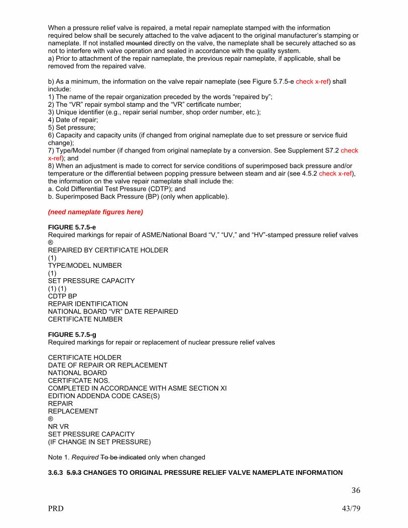
36
When a pressure relief valve is repaired, a metal repair nameplate stamped with the information required below shall be securely attached to the valve adjacent to the original manufacturer’s stamping or nameplate. If not installed mounted directly on the valve, the nameplate shall be securely attached so as not to interfere with valve operation and sealed in accordance with the quality system. a) Prior to attachment of the repair nameplate, the previous repair nameplate, if applicable, shall be removed from the repaired valve. b) As a minimum, the information on the valve repair nameplate (see Figure 5.7.5-e check x-ref) shall include: 1) The name of the repair organization preceded by the words “repaired by”; 2) The “VR” repair symbol stamp and the “VR” certificate number; 3) Unique identifier (e.g., repair serial number, shop order number, etc.); 4) Date of repair; 5) Set pressure; 6) Capacity and capacity units (if changed from original nameplate due to set pressure or service fluid change); 7) Type/Model number (if changed from original nameplate by a conversion. See Supplement S7.2 check x-ref); and 8) When an adjustment is made to correct for service conditions of superimposed back pressure and/or temperature or the differential between popping pressure between steam and air (see 4.5.2 check x-ref), the information on the valve repair nameplate shall include the: a. Cold Differential Test Pressure (CDTP); and b. Superimposed Back Pressure (BP) (only when applicable). (need nameplate figures here) FIGURE 5.7.5-e Required markings for repair of ASME/National Board “V,” “UV,” and “HV”-stamped pressure relief valves ® REPAIRED BY CERTIFICATE HOLDER (1) TYPE/MODEL NUMBER (1) SET PRESSURE CAPACITY (1) (1) CDTP BP REPAIR IDENTIFICATION NATIONAL BOARD “VR” DATE REPAIRED CERTIFICATE NUMBER FIGURE 5.7.5-g Required markings for repair or replacement of nuclear pressure relief valves CERTIFICATE HOLDER DATE OF REPAIR OR REPLACEMENT NATIONAL BOARD CERTIFICATE NOS. COMPLETED IN ACCORDANCE WITH ASME SECTION XI EDITION ADDENDA CODE CASE(S) REPAIR REPLACEMENT ® NR VR SET PRESSURE CAPACITY (IF CHANGE IN SET PRESSURE) Note 1. Required To be indicated only when changed 3.6.3 5.9.3 CHANGES TO ORIGINAL PRESSURE RELIEF VALVE NAMEPLATE INFORMATION
PRD 43/79

37
a) If the set pressure is changed, the set pressure, capacity, and blowdown, if applicable, on the original nameplate or stamping shall be marked out but left legible. The new capacity shall be based on that for which the valve was originally certified. b) If the service fluid is changed, the capacity, including units, on the original nameplate or stamping shall be marked out but left legible. The new capacity shall be based on that for which the valve was originally certified, or if a conversion has been made, as described in S7.2 (check x-ref) on the capacity certification for the valve as converted. c) If the Type/Model number is changed, the Type/Model number on the original nameplate shall be marked out but left legible. d) If the blowdown is changed, the blowdown on the original nameplate or stamping shall be marked out but left legible. The new blowdown may be based on the current ASME Code requirements. e) Incorrect information on the original manufacturer’s nameplate shall be marked out but left legible. Corrected information shall be indicated on the repair nameplate and noted on the document as required by the quality system. 3.6.4 5.9.4 TEST ONLY NAMEPLATE a) Where a valve has been tested and adjusted, as permitted by S7.10.1, (check x-ref) but not otherwise repaired, a “Test Only” nameplate shall be applied that contains the following information: 1) Name of responsible organization; 2) Date of test; 3) Set Pressure; and 4) Identification, such as “Test Only.” b) A “Test Only” nameplate is also recommended when periodic testing has been performed, even when no adjustments have been made, for the purpose of identifying the date the valve was tested. c) The existing repair nameplates, if applicable, shall not be removed during such testing. 3.6.5 5.9.5 REPLACEMENT OF ILLEGIBLE OR MISSING NAMEPLATES a) Illegible Nameplates When the information on the original manufacturer’s or assembler’s nameplate or stamping is illegible, but traceability can be confirmed, the nameplate or stamping will be augmented by a nameplate furnished by the “VR” stamp holder stamped “Duplicate.” It shall contain all information that originally appeared on the nameplate or valve, as required by the applicable section of the ASME Code, except the “V,” “HV,” or “UV” symbol and the National Board mark. The repair organization’s nameplate, with the “VR” stamp and other required data specified in 5.9.2, will make the repairer responsible to the owner and the Jurisdiction that the information on the duplicate nameplate is correct. b) Missing Nameplates When the original valve nameplate is missing, the repair organization is not authorized to perform repairs to the valve under the “VR” program, unless positive identification can be made to that specific valve and verification that the valve was originally stamped with an ASME “V” or UV” symbol or marked with an ASME “HV” symbol. Valves that can be positively identified will be equipped with a duplicate nameplate, as described in this section, in addition to the repairer’s “VR”-stamped nameplate. The repairer’s responsibilities for accurate data, as defined in 5.9.5(a) (Illegible Nameplates), shall apply. c) Marking of Original Code Stamp When a duplicate nameplate is affixed to a valve, as required by this section, it shall be marked “Sec. I,” “Sec. IV,” or “Sec. VIII,” as applicable, to indicate the original ASME Code stamping. 3.7 1.7 ACCREDITATION OF “VR” REPAIR ORGANIZATIONS 3.7.1 1.7.1 SCOPE a) These administrative rules and procedures are provided for those who wish to obtain a National Board Certificate of Authorization for use of the “VR” (Repair of Pressure Relief Valves) symbol stamp. It should be noted that the issuance of the “VR” stamp is not restricted to companies whose primary business is the repair of pressure relief valves, nor to manufacturers or assemblers that hold an ASME “V,” “HV,” “UV,” or “NV” Code symbol stamp. Owners and users of boilers and pressure vessels and other organizations that qualify in accordance with the National Board Rules and Regulations may also obtain the “VR” Certificate and stamp. b) In order to provide due process in the issuance, renewal, and revocation of “VR” symbol stamps and
PRD 44/79

38
certificates of authorization, the National Board Appeals Committee procedures provide an affected “VR” Certificate of Authorization applicant the right of appeal, or to provide additional information that may affect the Committee’s decision. 3.7.2 1.7.2 JURISDICTIONAL PARTICIPATION The National Board member jurisdiction in which the “VR” organization is located is encouraged to participate in the review and demonstration of the applicant’s quality system. The Jurisdiction may require participation in the review of the repair organization and the demonstration and acceptance of the repair organization’s quality system manual. 3.7.3 1.7.3 GENERAL RULES The general rules of the National Board “VR” certification program apply only to the repair of National Board capacity certified ASME Code Section I “V” stamped, Section IV “HV” marked, and Section VIII “UV” stamped pressure relief valves that: a) Have been in service or have been exposed to environmental or other conditions such that there is reason to question their ability to perform equivalent to the standards for new valves; or b) Any or all of the valve’s external adjustment seals have been broken, opened, or otherwise disturbed, regardless of the valve’s age or service status. 3.7.4 1.7.4 REPAIR OF NUCLEAR VALVES Provided that the requirements of Supplement 9 check x-ref and applicable requirements of these rules are met, the “VR” certificate may be extended to apply to the repair of any ASME Code Section III, Class 1, 2, or 3, pressure relief devices that have been capacity certified by the National Board and have been in service, regardless of their intended function, in a nuclear system. 3.7.5 1.7.5 ISSUANCE AND RENEWAL OF THE “VR” CERTIFICATE OF AUTHORIZATION 3.7.5.1 1.7.5.1 GENERAL Authorization to use the stamp bearing the official National Board “VR” symbol as shown in Section 5 of this Part, will be granted by the National Board pursuant to the provisions of the following administrative rules and procedures. Supplement 9 check x-ref of this Part, provides rules for the repair of ASME Section III “NV” stamped pressure relief devices. 3.7.5.2 1.7.5.2 ISSUANCE OF CERTIFICATE a) Repair organizations, manufacturers, assemblers, or users that make repairs to the American Society of Mechanical Engineers (ASME) Code symbol, stamped or marked (as applicable), and The National Board of Boiler and Pressure Vessel Inspectors (National Board) capacity certified pressure relief valves may apply to the National Board for a Certificate of Authorization to use the “VR” symbol. The National Board may at any time, through the NBIC Committee, modify the regulations concerning the issuance and use of such valve repair symbol. All such modified regulations shall become binding upon holders of valid Valve Repair Certificates of Authorization. b) Authorization to use the “VR” stamp may be granted or withheld by the National Board in its absolute discretion. If authorization is granted and proper administrative fees paid, a Certificate of Authorization will be issued evidencing permission to use such a symbol, expiring on the triennial anniversary date. The certificate will be signed by the National Board Chairman of the National Board of Trustees, the Executive Director, or any other duly authorized officer. c) The certificate shall list the physical, permanent address of record for the certificate holder’s shop/plant. For field-only scopes, this address of record shown on the Certificate of Authorization is where administrative, technical, and quality aspects of the business are controlled. 3.7.5.3 1.7.5.3 RENEWAL OF CERTIFICATE The Certificate of Authorization is renewable every three (3) years subject to a review of the Quality System by a representative of the National Board, review and acceptance of the representative’s report by the National Board, and successful completion of capacity verification tests. See 1.7.8 check x-ref for
PRD 45/79

39
exceptions. The applicant should apply to the National Board for renewal of authorization and re-issuance of the certificate prior to the date of expiration. The National Board reserves the absolute right to cancel, refuse to issue, or renew such authorization. 3.7.5.4 1.7.5.4 REVIEW OF APPLICANT’S FACILITY a) Before issuance or renewal of pressure relief “VR” Certificates of Authorization, the repair organization, its written quality system, and its facilities are subject to a review and verification of implementation of its quality system by a representative of the National Board. The implementation demonstration shall include, as a minimum, disassembly, inspection, repair, application of special processes, reassembly, setting, and testing of valves within the scope of the applicant’s quality system. b) The applicant shall repair and submit for verification testing one (1) valve for each Code section (except Section III) and test fluid (steam, air/gas, liquid) which will appear on the Certificate of Authorization. A minimum of two (2) valves are required regardless of Code sections or test fluid. The valves shall be within the capabilities of the National Board accepted laboratory. When an applicant is using the provisions of 4.5.2, the applicant shall submit one additional Section VIII steam valve set on air for verification testing on steam. c) The applicant shall have a copy of the National Board Pressure Relief Device Certifications publication, NB-18, dated within one year (available from the National Board Web page), the latest edition and addenda of the National Board Inspection Code (NBIC), all parts; and the ASME Code section(s) that the organization is including in its scope. d) It is the responsibility of the valve repair organization to make arrangements for this review. Certificates cannot be issued or renewed until the National Board is in receipt of approval of this review. Wherever possible, National Board reviews of valve repair organizations shall be coordinated with ASME reviews, when applicable. e) For field-only repair scopes, the review shall encompass both the applicant’s address of record and field repair demonstration site. The demonstration site shall be representative of that typically encountered by the applicant (see 1.7.5.6). 3.7.5.5 1.7.5.5 VERIFICATION TESTING a) Before the “VR” Certificate of Authorization and stamps may be issued or renewed, the demonstration valves must successfully complete capacity and operational verification tests at a National Board accepted testing laboratory. See 1.7.5.6 and 1.7.8 check x-ref for exceptions. The valves shall be typical of those repaired by the organization and within the capabilities of the testing laboratory. b) Tests conducted at the accepted testing laboratory shall be witnessed by a representative of the National Board. The purpose of the tests is to ensure that the repairs have been satisfactorily carried out and the function and operation of the valves meet the requirements of the section of the ASME Code to which they were manufactured. c) Valves not meeting the function or operational requirements of the section of the ASME Code to which they were manufactured shall be considered to have failed. Replacement valves shall be repaired and selected for testing as stated above, at a rate of two (2) valves for each one (1) that failed. 1) If either or both of these replacement valves fail to meet the above criteria, the applicant shall document the cause of the noted deficiencies and actions taken to guard against future occurrence. Upon acceptance of this information by the National Board, one (1) additional valve for each replacement valve that failed shall be repaired and tested. The valve(s) shall be of the same ASME Code Section, fluid and set pressure scope, as the valve previously failing to meet the test requirement. 2) Failure of this valve(s) to meet the ASME Code to which the valve was manufactured shall be cause for consideration by the National Board of revocation of the “VR” Certificate of Authorization or acceptance of alternative corrective action. 3.7.5.6 1.7.5.6 VERIFICATION TESTING ALTERNATIVES a) In such cases where all valves repaired by the applicant for a specified ASME Code Section or test fluid exceed the capabilities of the accepted testing laboratory, valves for that ASME Code Section or test fluid shall be selected as specified in 1.7.5.4, and a demonstration test shall be successfully performed in lieu of verification testing specified in 1.7.5.5 above. The demonstration tests shall be conducted at a facility mutually agreeable to the National Board representative, the facility owner, and the applicant. The purpose of these tests is to demonstrate, in the presence of a National Board representative, that the repaired valves shall have adequate seat tightness at the maximum expected operating pressure prior to
PRD 46/79

40
lifting, shall open within the required set pressure tolerance, operate consistently without chatter, and reclose within the required blowdown. b) If a valve lift-assist device is used by the applicant to establish set pressure after repairs, this device must also be used to set the demonstration valves. c) If either of these valves fail to meet the above criteria, then replacement valves shall be repaired and tested at a rate of two valves for each one that failed. 1) If either or both of these replacement valves fail to meet the above criteria, the applicant shall document the cause of the noted deficiencies and actions taken to guard against future occurrence. Upon acceptance of this information by the National Board, one (1) additional valve for each replacement valve that failed shall be repaired and tested. The valve(s) shall be of the same ASME Code section, fluid, and set pressure scope as the valve previously failing to meet the test requirement. 2) Failure of this valve(s) to meet the ASME Code to which the valve was manufactured shall be cause for consideration by the National Board of revocation of the “VR” Certificate of Authorization or acceptance of alternative corrective action. 3.7.6 1.7.6 USE OF THE “VR” AUTHORIZATION 3.7.6.1 1.7.6.1 TECHNICAL REQUIREMENTS The administrative requirements of 1.7 for use of the “VR” stamp shall be used in conjunction with the technical requirements for valve repair as described in NBIC Part 4, sections 3.0 through 3.6 Supplement 7 of the NBIC. Those requirements shall be mandatory when a “VR” repair is performed. 3.7.6.2 1.7.6.2 STAMP USE Each “VR” symbol stamp shall be used only by the repair firm within the scope, limitations, and restrictions under which it was issued. 3.7.6.3 1.7.6.3 RETURN OF STAMP Each applicant shall agree, if authorization to use the stamp is granted, that the stamp is at all times the property of the National Board and will be promptly returned upon demand. If the applicant discontinues the repair of such valves or if the “VR” Certificate of Authorization issued to such applicant has expired and no new certificate has been issued, the stamp will be returned to the National Board. 3.7.6.4 1.7.6.4 MULTIPLE LOCATIONS A holder of a National Board “VR” stamp shall not permit any others to use the “VR” symbol stamp loaned to it by the National Board. When a repair organization, manufacturer, or user has a repair department and/or equipment in fixed plants or shops located in more than one geographical area, it must submit separate applications for each plant or shop with the addresses of all such repair locations. 3.7.6.5 1.7.6.5 CERTIFICATE OF AUTHORIZATION CONTENTS Qualification for repair location (shop, shop and field, or field only), code section (Section I, III, IV, and/or VIII valves), special processes, and test media shall be specified on the repair organization’s “VR” Certificate of Authorization. 3.7.6.6 1.7.6.6 CHANGES TO VR CERTIFICATES OF AUTHORIZATION a) When a “VR” Certificate Holder intends to change the address of record (location), the certificate holder shall notify the National Board in writing prior to relocating. The new facilities and related quality system for the new location shall be reviewed in accordance with 1.7.5.4. Issuance of a new Certificate of Authorization is subject to the procedures herein. b) When a “VR” Certificate Holder intends to change ownership or scope, the certificate holder shall notify the National Board in writing prior to the change. A review, in accordance with 1.7.5.4, may be required depending upon the nature and extent of the change to the quality system manual, repair procedures, or facilities. Issuance of a new Certificate of Authorization is subject to the procedures herein. 3.7.6.7 1.7.6.7 ISSUANCE OF MORE THAN ONE “VR” SYMBOL STAMP TO A CERTIFICATE OF
PRD 47/79

41
AUTHORIZATION HOLDER The holder of a Certificate of Authorization may obtain more than one “VR” symbol stamp provided its quality system manual controls the use of such stamps from the address of record shown on the Certificate of Authorization. 3.7.7 1.7.7 QUALITY SYSTEM 3.7.7.1 1.7.7.1 GENERAL Each applicant for a new or renewed “VR” Certificate of Authorization shall have and maintain a quality system which shall establish that all of these rules and administrative procedures and applicable ASME Code requirements, including material control, fabrication, machining, welding, examination, setting, testing, inspection, sealing, and stamping will be met. 3.7.7.2 1.7.7.2 WRITTEN DESCRIPTION A written description, in the English language, of the system the applicant will use shall be available for review and shall contain, as a minimum, the features set forth in 1.7.7.5. This description may be brief or voluminous, depending upon the projected scope of work, and shall be treated confidentially. In general, the quality system shall describe and explain what documents and procedures the repair firm will use to validate a valve repair. 3.7.7.3 1.7.7.3 REVIEW A review of the applicant’s quality system will be performed by a representative of the National Board. The review will include a demonstration of the implementation of the provisions of the applicant’s quality system. 3.7.7.4 1.7.7.4 MAINTENANCE OF CONTROLLED COPY Each applicant to whom a “VR” Certificate of Authorization is issued shall maintain thereafter a controlled copy of the accepted quality system manual with the National Board. Except for changes that do not affect the quality system, revisions to the quality system manual shall not be implemented until such revisions are accepted by the National Board. 3.7.7.5 1.7.7.5 OUTLINE OF REQUIREMENTS FOR A QUALITY SYSTEM The following establishes the minimum requirements of the written description of the quality system. It is required that each valve repair organization develop its own quality system that meets the requirements of its organization. For this reason it is not possible to develop one quality system that could apply to more than one organization. The written description shall include, as a minimum, the following features: a) Title Page The title page shall include the name and address of the company to which the National Board Certificate of Authorization is to be issued. b) Revision Log A revision log is required to assure revision control of the quality system manual. The log should contain sufficient space for date, description and section of revision, company approval, and National Board acceptance. c) Contents Page The contents page should list and reference, by paragraph and page number, the subjects and exhibits contained therein. d) Statement of Authority and Responsibility A statement of authority and responsibility shall be dated and signed by an officer of the company. It shall include: 1) A statement that the “VR” stamp shall be applied only to pressure relief valves that meet both of the following conditions: a. Are stamped with an ASME “V”, “UV”, or “NV” Code symbol or marked with an ASME “HV” symbol and have been capacity certified by the National Board; and b. Have been disassembled, inspected, and repaired by the Certificate Holder such that the valves’
PRD 48/79

42
condition and performance are equivalent to the standards for new valves. 2) The title of the individual responsible to ensure that the quality system is followed and who has authority and freedom to effect the responsibility; 3) A statement that if there is a disagreement in the implementation of the written quality system, the matter is to be referred to a higher authority in the company for resolution; and 4) The title of the individual authorized to approve revisions to the written quality system and the method by which such revisions are to be submitted to the National Board for acceptance before implementation. e) Organization Chart A chart showing the relationship between management, purchasing, repairing, inspection, and quality control personnel is required and shall reflect the actual organization in place. f) Scope of Work 1) The scope of work section shall indicate the scope and type of valve repairs, including conversions the organization is capable of and intends to perform. The location of repairs (shop, shop and field, or field only), ASME Code Section(s) to which the repairs apply, the test medium (air, gas, liquid, or steam, or combinations thereof), and special processes (machining, welding, postweld heat treatment, or nondestructive examination, or combinations thereof) shall be specifically addressed. 2) The types and sizes of valves to be repaired, pressure ranges and other limitations, such as engineering and test facilities, should also be addressed. g) Drawings and Specification Control The drawings and specification control system shall provide procedures assuring that the latest applicable drawings, specifications, and instructions required are used for valve repair, including conversions, inspection, and testing. h) Material and Part Control The material and part control section shall describe purchasing, receiving, storage, and issuing of parts. 1) State the title of the individual responsible for the purchasing of all material. 2) State the title of the individual responsible for certification and other records as required. 3) All incoming material and parts shall be checked for conformance with the purchase order and, where applicable, the material specifications or drawings. Indicate how material or part is identified and how identity is maintained by the quality system. i) Repair and Inspection Program The repair and inspection program section shall include reference to a document (such as a report, traveler, or checklist) that outlines the specific repair and inspection procedures used in the repair of pressure relief valves. Repair procedures shall require verification that the critical parts meet the valve manufacturer’s specification. Supplement S7.14 outlines recommended procedures covering some specific items. Provisions shall be made to retain this document for a period of at least five years. 1) Each valve or group of valves shall be accompanied by the document referred to above for processing through the plant. Each valve shall have a unique identifier (i.e., repair serial number, shop order number, etc.) appearing on the repair documentation and repair nameplate such that traceability is established. 2) The document referred to above shall describe the original nameplate information, including the ASME Code symbol stamping and the repair nameplate information, if applicable. In addition, it shall include material checks, replacement parts, conversion parts (or both), reference to items such as the welding procedure specifications (WPS), fitup, NDE technique, heat treatment, and pressure test methods to be used. Application of the “VR” stamp to the repair nameplate shall be recorded in this document. Specific conversions performed with the new Type/Model number shall be recorded on the document. There shall be a space for “signoffs” at each operation to verify that each step has been properly performed. 3) The system shall include a method of controlling the repair or replacement of critical valve parts. The method of identifying each spring shall be indicated. 4) The system shall also describe the controls used to ensure that any personnel engaged in the repair of pressure relief valves are trained and qualified in accordance with Supplement S7. j) Welding, NDE, and Heat Treatment (when applicable) The quality system manual shall indicate the title of the person(s) responsible for and describe the system used in the selection, development, approval, and qualification of welding procedure specifications, and the qualification of welders and welding operators in accordance with the provisions of S7. 1) The quality system manual may include controls for the “VR” Certificate Holder to have the pressure relief valve part repaired by a National Board “R” Certificate Holder, per Supplement S7. 2) The completed Form R-1 shall be noted on and attached to the “VR” Certificate Holder’s document required in 1.7.7.5(i). Similarly, NDE and heat treatment techniques must be covered in the quality system manual. When outside services are used for NDE and heat treatment, the quality system manual shall describe the
PRD 49/79

43
system whereby the use of such services meet the requirements of the applicable section of the ASME Code. k) Valve Testing, Setting, and Sealing The system shall include provisions that each valve shall be tested, set, and all external adjustments sealed according to the requirements of the applicable ASME Code Section and the National Board. The seal shall identify the “VR” Certificate Holder making the repair. Abbreviations or initials shall be permitted, provided such identification is acceptable to the National Board. l) Valve Repair Nameplates An effective valve stamping system shall be established to ensure proper stamping of each valve as required by 5.9.2. The manual shall include a description of the nameplate or a drawing. m) Calibration 1) The manual shall describe a system for the calibration of examination, measuring, and test equipment used in the performance of repairs. Documentation of these calibrations shall include the standard used and the results. 2) All calibration standards shall be calibrated against certified equipment having known valid relationships to nationally recognized standards. n) Manual Control The quality system shall include: 1) Measures to control the issuance of and revisions to the quality system manual; 2) Provisions for a review of the system in order to maintain the manual current with these rules and the applicable sections of the ASME Code; 3) The title(s) of the individual(s) responsible for control, revisions, and review of the manual; 4) Provision of a controlled copy of the written quality system manual to be submitted to the National Board; and 5) Revisions shall be submitted for acceptance by the National Board prior to being implemented. o) Nonconformities The system shall establish measures for the identification, documentation, evaluation, segregation, and disposition of nonconformities. A nonconformity is a condition of any material, item, product, or process in which one or more characteristics do not conform to the established requirements. These may include, but are not limited to, data discrepancies, procedural and/or documentation deficiencies, or material defects. Also, the title(s) of the individual(s) involved in this process shall be included. p) Exhibits Forms used in the quality system shall be included in the manual with a written description. Forms exhibited should be marked SAMPLE and completed in a manner typical of actual valve repair procedures. q) Testing Equipment (See Supplement 5 for a guide on the sizing of pressure vessels used as part of pressure relief valve test equipment) The system shall include a means to control the development, addition, or modification of testing equipment to ensure the requirements of 4.5.1(b) are met. r) Field Repairs (See Supplement S7.7 check x-ref) If field repairs are included in the scope of work, the system shall address any differences or additions to the quality system required to properly control this activity, including the following: 1) Provisions for annual audits of field activities shall be included; 2) Provisions for receipt and inspection of replacement parts, including parts received from the owner-user, shall be addressed; 3) If owner-user personnel will assist with repairs, provisions for the use of owner user personnel shall be included; and 4) Provisions for use of owner-user measurement and test equipment, if applicable, shall be addressed. 3.7.8 1.7.8 ASME “V,” “HV,” OR “UV” CERTIFICATE HOLDERS a) A manufacturer holding a valid ASME Certificate of Authorization for use of an ASME “V”, “HV”, or “UV” Code symbol stamp may obtain the “VR” Certificate of Authorization for the repair of pressure relief valves covered by the ASME Certificate of Authorization and that meet the requirements of 1.7.3 check x-ref. This can be accomplished without a review of the facilities provided there is a written quality system to cover the scope of the repairs to be made and the repairs are carried out at the same location where the ASME valves are manufactured. Unless the repaired valves are tested on the same facilities and to the same procedures as new valves, two (2) repaired valves shall be selected by a National Board representative
PRD 50/79

44
for verification tests. b) The initial Certificate of Authorization shall be issued to expire concurrent with the ASME Certificate of Authorization. Subsequent certificates shall be renewed upon a successful review and verification of implementation of its quality system by a National Board representative. This review shall be performed concurrently with the ASME Certificate renewal review. c) A manufacturer may also perform field repairs of pressure relief valves covered by the ASME Certificate of Authorization provided the provisions of Supplement S7.7 are met. d) Assemblers holding ASME Certificates of Authorization shall qualify for the “VR” Certificate of Authorization as required elsewhere in these rules. e) The quality system manual shall be submitted for review and acceptance by the National Board. f) In order for an ASME Code symbol stamp holder to qualify for the National Board “VR” stamp, the following areas to the written quality system usually require attention. 1) Statement of Authority and Responsibility This should clearly indicate that valve repairs are carried out in accordance with the requirements and the rules of the National Board and the quality system manual. In addition, the scope and type of valve repairs covered by the manual should be indicated. 2) Organization Unless the functions which affect the quality of valve repairs are carried out by individuals other than those responsible for manufacturing or assembly, it should not be necessary to revise the organization chart. 3) General Quality Functions Usually quality system requirements regarding valve repairs may be controlled in the same manner as for ASME manufacturing or assembly provided applicable shop and/or field activities are covered. If this is the case, the applicant for the “VR” stamp should include in its quality system manual a separate section covering valve repairs that references the applicable section of the manual. For a more explicit explanation see 1.7.7.5, Outline of Requirements for a Quality System. 3.7.9 S7.7 FIELD REPAIR Repair organizations may obtain a “VR” Certificate of Authorization for field repair, either as an extension to their in-shop/plant scope, or as a field-only scope, provided that: a) Qualified technicians in the employ of the certificate holder perform such repairs; b) An acceptable quality system covering field repairs, including field audits, is maintained; c) Functions affecting the quality of the repaired valves are supervised from the address of record where the “VR” certification is issued. 3.7.9.1 S7.8 AUDIT REQUIREMENTS Upon issuance of a Certificate of Authorization, provided field repairs are performed, annual audits of the work carried out in the field shall be performed to ensure that the requirements of the certificate holder’s quality system are met. The audit shall include, but not be limited to, performance testing, in accordance with 4.5, of valve(s) that were repaired in the field. The audits shall be documented. 3.7.9.2 S7.9 USE OF OWNER-USER PERSONNEL For the repair of pressure relief valves at an owner-user’s facility for the owner-user’s own use, the “VR” Certificate Holder may utilize owner-user personnel to assist certificate holder technician(s) in the performance of repairs provided: a) The use of such personnel is addressed in the “VR” Certificate Holder’s quality system; b) The owner-user personnel are trained and qualified in accordance with Supplement S7.10 check x-ref; c) Owner-user personnel work under direct supervision and control of the “VR” Certificate Holder’s technician(s) during any stage of the repair when they are utilized; d) The “VR” Certificate Holder shall have the authority to assign and remove owner-user personnel at its own discretion; and e) The names of the owner-user personnel utilized are recorded on the document as required for a quality system. 3.8 S7.11 TRAINING AND QUALIFICATION OF PERSONNEL
PRD 51/79

45
S7.11.1 GENERAL 3.8.1 S7.11.2 CONTENTS OF TRAINING PROGRAM The repair organization shall establish a documented in-house training program. This program shall establish training objectives and provide a method of evaluating training effectiveness. As a minimum, training objectives for knowledge level shall include: a) Applicable ASME Code and NBIC requirements; b) Responsibilities within the organization’s quality system; and c) Knowledge of the technical aspects and mechanical skills for the applicable position held. 3.8.2 S7.11.3 QUALIFICATION OF PERSONNEL Each repair organization shall establish minimum qualification requirements for those positions within the organization as they directly relate to pressure relief valve repair. Each repair organization shall document the evaluation and acceptance of an individual’s qualification for the applicable position. 3.8.3 S7.11.4 ANNUAL REVIEW OF QUALIFICATION The repair organization shall annually review the qualifications of repair personnel to verify proficiency as well as compliance with the certificate holder’s quality system. This review shall include training records, documented evidence of work performed, and when necessary, monitoring job performance. The review shall be documented.
PRD 52/79

46
SUPPLEMENTS SUPPLEMENT 1 PRESSURE RELIEF VALVES ON THE LOW PRESSURE SIDE OF STEAM PRESSURE-REDUCING VALVES (was Part 1 Supplement 2) S1.1 S2.1 SCOPE a) The subject of protection of vessels in steam service connected to the low-pressure side of a steam-pressure-reducing valve is of considerable importance to proper operation of auxiliary equipment such as pressure cookers, hot-water heating systems, etc., operating at pressures below that which the primary boiler generating unit is operating. b) To automatically reduce the primary boiler pressure for such processing equipment, pressure-reducing valves are used. The manufacturers of such equipment have data available listing the volume of flow through reducing valves manufactured by them, but such data are not compiled in a form that the results can be deduced readily. To protect the equipment operating on the low pressure side of a pressure-reducing valve, safety valves of a relieving capacity sufficient to prevent an unsafe pressure rise in case of failure of the pressure-reducing valve, should be installed. c) The pressure-reducing valve is a throttling device, the design of which is based on certain diaphragm pressures opposed by spring pressure which, in turn, controls the opening through the valve. If the spring, the diaphragm, or any part of the pressure- reducing valve fails, steam will flow directly through the valve and the low pressure equipment will be subjected to the boiler pressure. To protect the equipment operating on the low pressure side of the pressure-reducing valve, safety valve(s) should be installed on the low pressure side of the pressure-reducing valve, which will provide a relieving capacity sufficient to prevent the pressure from rising above the system design pressure. d) In most cases pressure-reducing valves used for the reduction of steam pressures have the same pipe size on the inlet and outlet. In case of failure of a pressure-reducing valve, the safety valve on the low-pressure side must have a capacity to take care of the volume of steam determined by the high pressure side and the area of the pipe. S1.2 S2.2 SAFETY VALVE CAPACITY a) The capacity of the safety valve(s) on the low-pressure side of the pressure-reducing valve should be based on the capacity of the pressure-reducing valve when wide open or under maximum flow conditions or the flow capacity through the bypass valve. b) By using the formula in S2.3 below, Inspectors may calculate the required relieving capacities of the safety valve(s) installed on the low-pressure side of the pressure reducing valve. c) Usually a pressure-reducing valve has a bypass arrangement so that in case of failure of the pressure-reducing valve the boiler pressure may be short circuited into the low-pressure line without passing through the pressure-reducing valve. When determining the required relieving capacity of safety valves for the low-pressure side of the pressure-reducing valve, the steam flow through the bypass must be taken into consideration. S1.3 S2.3 CALCULATION OF SAFETY VALVE RELIEVING CAPACITY a) When a pressure-reducing valve is installed, there are two possibilities of introducing boiler pressure into the low-pressure system: 1) the failure of the pressure-reducing valve so that it remains wide open; and 2) the possibility of the bypass valve being open. b) It is necessary therefore, to determine the flow under both circumstances in paragraph a) above and check that the size of the safety valve under either condition will be adequate. The following formula should be used: 1) steam flow, W in lbs/hr (kg/hr) through the pressure-reducing valve W = AKC where,
PRD 53/79

47
A = internal area in sq. in. (sq. mm) of the inlet pipe size of the pressure reducing valve (see S2.5) K = flow coefficient for the pressure reducing valve (see S2.4) C = flow of saturated steam through a 1 sq. in. (1 sq. mm) pipe at various pressure differentials from Tables S2.3-a, S2.3-b, or S2.3-c. (for U.S. Customary units) or Tables S2.3M-a, S2.3M-b, or S2.3M-c ( for metric units). 2) steam flow, W in lbs/hr (kg/hr) through the by-pass valve W = A1 K1 C1 where, A1 = internal area in sq. in. (sq. mm) of the pipe size of the bypass around the pressure-reducing valve K1 = flow coefficient for the bypass valves (see S2.4) C1 = flow of saturated steam through a 1 sq. in. (1 aq. mm) pipe at various pressure differentials from Tables S2.3-a, S2.3-b, or S2.3-c. (for U.S. Customary units) or Tables S2.3M-a, S2.3M-b, or S2.3M-c ( for metric units). S 1.4 S2.4 STEAM FLOW WHEN FLOW COEFFICIENTS ARE NOT KNOWN a) It is possible that the flow coefficients K and K1 may not be known and in such instances for approximating the flow, a factor of 1/3 may be substituted for K and 1/2 for K1. The formulas in S2.3 then becomes: W = 1/3 AC for the capacity through the pressure-reducing valve; and W = 1/2 A1 C1 for the capacity through the bypass valve. b) Caution should be exercised when substituting these factors for the actual coefficients since this method will provide approximate values only and the capacities so obtained may in fact be lower than actual. It is recommended that the actual flow coefficient be obtained from the pressure-reducing valve manufacturer and reference books be consulted for the flow coefficient of the bypass valve.
(Tables did not import correctly) TABLE S2.3-a Capacity of Saturated Steam, in lb./hr., per sq. in. of Pipe Area
1500 1450 1400 1350 1300 1250 1200 1150 1100 1050 1000 950 900 1000 76560 72970 69170 64950 60540 55570 49930 43930 35230 25500 . . . . . . . . . . . . . . . 950 77430 74180 70760 67000 63100 58770 53920 48610 42380 34890 24910 . . . . . . . . . . 900 77750 74810 71720 68340 64870 61040 56820 52260 47050 41050 33490 23960 . . . . . 850 77830 74950 72160 69130 66020 62610 58900 54930 50480 45470 39660 29080 23190 800 . . . . . 75070 72330 69490 66700 63680 60390 56910 53060 48800 43980 38340 31610 750 . . . . . . . . . . . . . . . 69610 66880 64270 61260 58200 54840 51170 47080 42420 37110 700 . . . . . . . . . . . . . . . . . . . . 66900 64270 61520 58820 55870 52670 49170 45230 40860 650 . . . . . . . . . . . . . . . . . . . . . . . . . . . . . . 61550 58860 56260 53480 50440 47070 43400 600 . . . . . . . . . . . . . . . . . . . . . . . . . . . . . . . . . . . 58980 56270 53660 51020 48470 45010 550 . . . . . . . . . . . . . . . . . . . . . . . . . . . . . . . . . . . . . . . . . . . . . 53810 51040 48470 45800 500 . . . . . . . . . . . . . . . . . . . . . . . . . . . . . . . . . . . . . . . . . . . . . . . . . . . . . . . . . . . . 45850 450 . . . . . . . . . . . . . . . . . . . . . . . . . . . . . . . . . . . . . . . . . . . . . . . . . . . . . . . . . . . . 45870 400 . . . . . . . . . . . . . . . . . . . . . . . . . . . . . . . . . . . . . . . . . . . . . . . . . . . . . . . . . . . . . . . . . 350 . . . . . . . . . . . . . . . . . . . . . . . . . . . . . . . . . . . . . . . . . . . . . . . . . . . . . . . . . . . . . . . . . 300 . . . . . . . . . . . . . . . . . . . . . . . . . . . . . . . . . . . . . . . . . . . . . . . . . . . . . . . . . . . . . . . . . 250 . . . . . . . . . . . . . . . . . . . . . . . . . . . . . . . . . . . . . . . . . . . . . . . . . . . . . . . . . . . . . . . . . 200 . . . . . . . . . . . . . . . . . . . . . . . . . . . . . . . . . . . . . . . . . . . . . . . . . . . . . . . . . . . . . . . . . 175 . . . . . . . . . . . . . . . . . . . . . . . . . . . . . . . . . . . . . . . . . . . . . . . . . . . . . . . . . . . . . . . . . 150 . . . . . . . . . . . . . . . . . . . . . . . . . . . . . . . . . . . . . . . . . . . . . . . . . . . . . . . . . . . . . . . . . 125 . . . . . . . . . . . . . . . . . . . . . . . . . . . . . . . . . . . . . . . . . . . . . . . . . . . . . . . . . . . . . . . . . 110 . . . . . . . . . . . . . . . . . . . . . . . . . . . . . . . . . . . . . . . . . . . . . . . . . . . . . . . . . . . . . . . . . 100 . . . . . . . . . . . . . . . . . . . . . . . . . . . . . . . . . . . . . . . . . . . . . . . . . . . . . . . . . . . . . . . . . 85 . . . . . . . . . . . . . . . . . . . . . . . . . . . . . . . . . . . . . . . . . . . . . . . . . . . . . . . . . . . . . . . . . 75 . . . . . . . . . . . . . . . . . . . . . . . . . . . . . . . . . . . . . . . . . . . . . . . . . . . . . . . . . . . . . . . . . 60 . . . . . . . . . . . . . . . . . . . . . . . . . . . . . . . . . . . . . . . . . . . . . . . . . . . . . . . . . . . . . . . . . 50 . . . . . . . . . . . . . . . . . . . . . . . . . . . . . . . . . . . . . . . . . . . . . . . . . . . . . . . . . . . . . . . . . 40 . . . . . . . . . . . . . . . . . . . . . . . . . . . . . . . . . . . . . . . . . . . . . . . . . . . . . . . . . . . . . . . . . 30 . . . . . . . . . . . . . . . . . . . . . . . . . . . . . . . . . . . . . . . . . . . . . . . . . . . . . . . . . . . . . . . . . 25 . . . . . . . . . . . . . . . . . . . . . . . . . . . . . . . . . . . . . . . . . . . . . . . . . . . . . . . . . . . . . . . . .
PRD 54/79
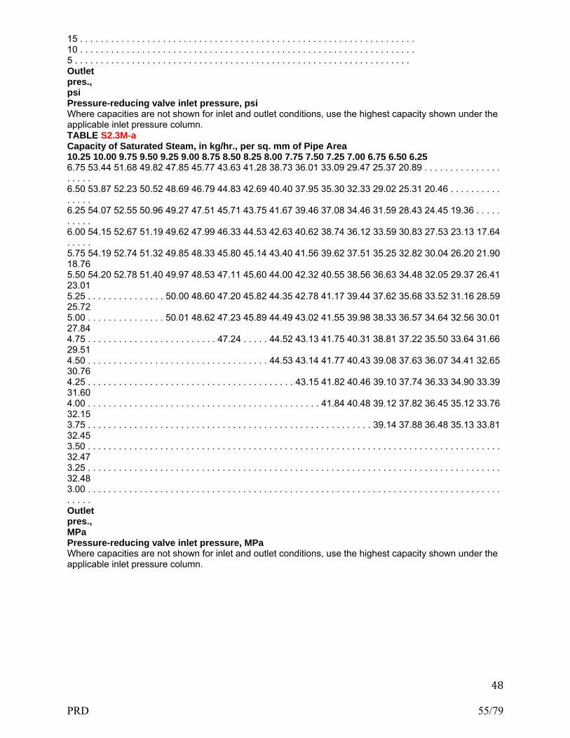
48
15 . . . . . . . . . . . . . . . . . . . . . . . . . . . . . . . . . . . . . . . . . . . . . . . . . . . . . . . . . . . . . . . . . 10 . . . . . . . . . . . . . . . . . . . . . . . . . . . . . . . . . . . . . . . . . . . . . . . . . . . . . . . . . . . . . . . . . 5 . . . . . . . . . . . . . . . . . . . . . . . . . . . . . . . . . . . . . . . . . . . . . . . . . . . . . . . . . . . . . . . . . Outlet pres., psi Pressure-reducing valve inlet pressure, psi Where capacities are not shown for inlet and outlet conditions, use the highest capacity shown under the applicable inlet pressure column. TABLE S2.3M-a Capacity of Saturated Steam, in kg/hr., per sq. mm of Pipe Area 10.25 10.00 9.75 9.50 9.25 9.00 8.75 8.50 8.25 8.00 7.75 7.50 7.25 7.00 6.75 6.50 6.25 6.75 53.44 51.68 49.82 47.85 45.77 43.63 41.28 38.73 36.01 33.09 29.47 25.37 20.89 . . . . . . . . . . . . . . . . . . . . 6.50 53.87 52.23 50.52 48.69 46.79 44.83 42.69 40.40 37.95 35.30 32.33 29.02 25.31 20.46 . . . . . . . . . . . . . . . 6.25 54.07 52.55 50.96 49.27 47.51 45.71 43.75 41.67 39.46 37.08 34.46 31.59 28.43 24.45 19.36 . . . . . . . . . . 6.00 54.15 52.67 51.19 49.62 47.99 46.33 44.53 42.63 40.62 38.74 36.12 33.59 30.83 27.53 23.13 17.64 . . . . . 5.75 54.19 52.74 51.32 49.85 48.33 45.80 45.14 43.40 41.56 39.62 37.51 35.25 32.82 30.04 26.20 21.90 18.76 5.50 54.20 52.78 51.40 49.97 48.53 47.11 45.60 44.00 42.32 40.55 38.56 36.63 34.48 32.05 29.37 26.41 23.01 5.25 . . . . . . . . . . . . . . . 50.00 48.60 47.20 45.82 44.35 42.78 41.17 39.44 37.62 35.68 33.52 31.16 28.59 25.72 5.00 . . . . . . . . . . . . . . . 50.01 48.62 47.23 45.89 44.49 43.02 41.55 39.98 38.33 36.57 34.64 32.56 30.01 27.84 4.75 . . . . . . . . . . . . . . . . . . . . . . . . . 47.24 . . . . . 44.52 43.13 41.75 40.31 38.81 37.22 35.50 33.64 31.66 29.51 4.50 . . . . . . . . . . . . . . . . . . . . . . . . . . . . . . . . . . . 44.53 43.14 41.77 40.43 39.08 37.63 36.07 34.41 32.65 30.76 4.25 . . . . . . . . . . . . . . . . . . . . . . . . . . . . . . . . . . . . . . . . 43.15 41.82 40.46 39.10 37.74 36.33 34.90 33.39 31.60 4.00 . . . . . . . . . . . . . . . . . . . . . . . . . . . . . . . . . . . . . . . . . . . . . 41.84 40.48 39.12 37.82 36.45 35.12 33.76 32.15 3.75 . . . . . . . . . . . . . . . . . . . . . . . . . . . . . . . . . . . . . . . . . . . . . . . . . . . . . . . 39.14 37.88 36.48 35.13 33.81 32.45 3.50 . . . . . . . . . . . . . . . . . . . . . . . . . . . . . . . . . . . . . . . . . . . . . . . . . . . . . . . . . . . . . . . . . . . . . . . . . . . . . . . . 32.47 3.25 . . . . . . . . . . . . . . . . . . . . . . . . . . . . . . . . . . . . . . . . . . . . . . . . . . . . . . . . . . . . . . . . . . . . . . . . . . . . . . . . 32.48 3.00 . . . . . . . . . . . . . . . . . . . . . . . . . . . . . . . . . . . . . . . . . . . . . . . . . . . . . . . . . . . . . . . . . . . . . . . . . . . . . . . . . . . . . Outlet pres., MPa Pressure-reducing valve inlet pressure, MPa Where capacities are not shown for inlet and outlet conditions, use the highest capacity shown under the applicable inlet pressure column.
PRD 55/79

49
SUPPLEMENT 2 PRESSURE DIFFERENTIAL BETWEEN SAFETY OR SAFETY RELIEF VALVE SETTING AND BOILER OR PRESSURE VESSEL OPERATING PRESSURE (Was Part 2, Supplement 8) S 2.1 S8.1 SCOPE If a safety valve or safety relief valve is subjected to pressure at or near its set pressure, it will tend to weep or simmer, and deposits may accumulate in the seat and disk area. Eventually, this can cause the valve to freeze closed and thereafter the valve could fail to open at the set pressure. Unless the source of pressure to the boiler or pressure vessel is interrupted, the pressure could exceed the rupture pressure of the vessel. It is important that the pressure differential between the valve set pressure and the boiler or pressure vessel operating pressure is sufficiently large to prevent the valve from weeping or simmering. S2.2 S8.2 HOT WATER HEATING BOILERS For hot-water heating boilers, the recommended pressure differential between the pressure relief valve set pressure and the boiler operating pressure should be at least 10 psi (70 kPa), or 25% of the boiler operating pressure, whichever is greater. Two examples follow: a) If the safety relief valve of a hot-water heating boiler is set to open at 30 psi (200 kPa), the boiler operating pressure should not exceed 20 psi (140 kPa). b) If the safety relief valve of a hot water heating boiler is set to open at 100 psi (700 kPa), the boiler operating pressure should not exceed 75 psi (520 kPa). Section IV of the ASME Code does not require that safety relief valves used on hot water heating boilers have a specified blowdown. Therefore, to help ensure that the safety relief valve will close tightly after opening and when the boiler pressure is reduced to the normal operating pressure, the pressure at which the valve closes should be well above the operating pressure of the boiler. S2.3 S8.3 STEAM HEATING BOILERS For steam heating boilers, the recommended pressure differential between the safety valve set pressure and boiler operating pressure should be at least 5 psi (35 kPa), i.e., the boiler operating pressure should not exceed 10 psi (70 kPa). Since some absorption-type refrigeration systems use the steam heating boiler for their operation, the boiler operating pressure may exceed 10 psi (70 kPa). If the boiler operating pressure is greater than 10 psi (70 kPa), it should not exceed 15 psi (100 kPa), minus the blowdown pressure of the safety valve. This recommendation can be verified by increasing the steam pressure in the boiler until the safety valve pops, then slowly reducing the pressure until it closes, to ensure that this closing pressure is above the operating pressure. S2.4 S8.4 POWER BOILERS For power boilers (steam), the recommended pressure differentials between the safety valve set pressure and the boiler operating pressure are as follows: (following to be prepared in table format) MINIMUM PRESSURE DIFFERENTIAL AS PERCENTAGE OF BOILER DESIGN PRESSURE over 15 psi to 300 psi (100 KPa to 2.10 MPa): 10% but not less than 7 psi (50 KPa) over 300 psi to 1000 psi (2.14 MPa to 6.89 MPa): 7% but not less than 30 psi (200 KPa) over 1000 psi to 2000 psi (6.89 MPa to 13.8 MPa): 5% but not less than 70 psi (480 KPa) over 2000 psi (13.8 MPa): per designer’s judgment Notes: 1. Above 2000 psi (13.8 MPa) the pressure differential between operating pressure and the maximum allowable working pressure is a matter for the designer’s judgment , taking into consideration such factors as satisfactory operating experience and the intended service conditions. 2. Safety relief valves in hot water service are more susceptible to damage and subsequent leakage, than safety valves relieving steam. It is recommended that the maximum allowable working pressure of
PRD 56/79

50
the boiler and safety relief valve setting for high-temperature hot -water boilers be selected substantially higher than the desired operating pressure, so as to minimize the time the safety relief valve must lift. 3. For organic fluid vaporizers a pressure differential of 40 psi (280 kPa) is recommended. S2.5 S8.5 PRESSURE VESSELS Due to the variety of service conditions and the various designs of pressure relief valves, only general guidelines can be given regarding differentials between the set pressure of the valve and the operating pressure of the vessel. Operating difficulty will be minimized by providing an adequate differential for the application. The following is general advisory information on the characteristics of the intended service and of the pressure relief valves that may bear on the proper pressure differential selection for a given application. These considerations should be reviewed early in the system design since they may dictate the maximum allowable working pressure of the system. To minimize operational problems it is imperative that the user consider not only normal operating conditions of the fluids (liquids or gases), pressures, and temperatures, but also start-up and shutdown conditions, process upsets, anticipated ambient conditions, instrument response time, and pressure surges due to quick-closing valves, etc. When such conditions are not considered, the pressure relief devices may become, in effect, a pressure controller, a duty for which it was not designed. Additional consideration should be given to the hazard and pollution associated with the release of the fluid. Larger differentials may be appropriate for fluids which are toxic, corrosive, or exceptionally valuable. The blowdown characteristics and capabilities are the first consideration in selecting a compatible valve and operating margin. After a self-actuated release of pressure, the valve must be capable of reclosing above the normal operating pressure. For example: if the valve is set at 100 psi (700 kPa) with a 7% blowdown, it will close at 93 psi (640 kPa). The operating pressure must be maintained below 93 psi (640 kPa) in order to prevent leakage or flow from a partially open valve. Users should exercise caution regarding the blowdown adjustment of large, spring-loaded valves. Test facilities, whether owned by the manufacturer, repair house, or user, may not have sufficient capacity to accurately verify the blowdown setting. The setting cannot be considered accurate unless made in the field on an actual installation. Pilot operated valves represent a special case from the standpoint of both blowdown and tightness. The pilot portion of some pilot operated valves can be set at blowdowns as short as 2%. This characteristic is not, however, reflected in the operation of the main valve in all cases. The main valve can vary considerably from the pilot depending on the location of the two components in the system. If the pilot is installed remotely from the main valve, significant time and pressure lags can occur, but reseating of the pilot ensures reseating of the main valve. The pressure drop in connecting piping between the pilot and the main valve must not be excessive, otherwise the operation of the main valve will be adversely affected. Tightness capability is another factor affecting valve selection, whether spring-loaded or pilot operated. Tightness varies somewhat depending on whether metal or resilient seats are specified and also on such factors as corrosion and temperature. The required tightness and test method should be specified to comply at a pressure not lower than the normal operating pressure of the process. It should be remembered that any degree of tightness obtained should not be considered permanent. Service operation of a valve almost invariably reduces the degree of tightness. The following minimum pressure differentials are recommended unless the safety or safety relief valve has been designed or tested in a specific or similar service and a smaller differential has been recommended by the manufacturer: (following to be prepared in table format) a) for set pressures up to 70 psi (480 kPa), the recommended pressure differential is 5 psi (35 kPa); b) for set pressure between 70 and 1000 psi (480 kPa and 6.89 MPa), the recommended pressure differential is 10% of set pressure; and c) for set pressures above 1000 psi (6.89MPa), the recommended pressure differential is 7% of set pressure.
PRD 57/79

51
SUPPLEMENT 3 GUIDE TO JURISDICTIONS FOR AUTHORIZATION OF OWNERS-USERS TO MAKE ADJUSTMENTS TO PRESSURE RELIEF VALVES (WAS PART 3 S7.10) S3.1 S7.10.1 GENERAL The Jurisdiction may authorize properly trained and qualified employees of boiler and pressure owners-users or their designees to restore set pressure and/or performance of pressure relief valves. All external adjustments shall be resealed with a seal identifying the responsible organization and a metal tag that identifies the organization and the date the adjustment shall be installed. S3.2 S7.10.2 TRAINING a) The user shall establish a documented in house training program. This program shall establish training objectives and provide a method of evaluating the training effectiveness. As a minimum, training objectives for knowledge level shall include: 1) Applicable ASME Code and NBIC requirements; 2) Responsibilities within the organization’s quality system; 3) Knowledge of the technical aspects and mechanical skills for making set pressure and/or blowdown adjustments to pressure relief valves; 4) Knowledge of the technical aspects and mechanical skills for marking of pressure relief valve adjustments. b) If the user established a designee, the designee shall establish a training program and make their documentation available to the user and the jurisdictional authority. S3.3 S7.10.3 DOCUMENTATION Each user shall document the evaluation and acceptance of an employee’s or designee’s qualifications. S3.4 S7.10.4 QUALITY SYSTEM a) A written quality system shall be established by either the user or the designee with a written description available to the jurisdictional authority. b) The written description shall include at a minimum: 1) Calibration of Test Equipment: This shall describe a system for the calibration of measuring and test equipment. Documentation of these calibrations shall include the standard used and the results. Calibration standards shall be calibrated against the equipment having valid relationships to nationally recognized standards. 2) Valve Testing, Setting, and Sealing: This system shall include provisions that each valve shall be tested, set, and all external adjustments sealed according to the requirements of the applicable ASME Code Section and S7.10.1(a). 3) Valve Marking: An effective marking system shall be established to ensure proper marking of the metal tag required by S7.10.1(a). The written quality system shall include a description or drawing of the metal tag. S3.5 S7.10.5 EXTERNAL ADJUSTMENTS Only external adjustments to restore the required set pressure and/or performance of a pressure relief valve shall be made under the provisions of S3.1 S7.10.1. S3.6 S7.10.6 REPAIRS If disassembly, change of set pressure, or additional repairs are necessary, the valve shall be repaired by an organization that meets the requirements of the NBIC.
PRD 58/79

52
SUPPLEMENT 4 RECOMMENDED PROCEDURES FOR REPAIRING PRESSURE RELIEF VALVES ( Was supplement S7.14) S4.1 S7.14.1 INTRODUCTION a) It is essential that the repair organization establish basic, specific procedures for the repair of pressure relief valves. The purpose of these recommended procedures is to provide the repair organization with guidelines for this important aspect of valve repair. It is realized that there are many types of valves and conditions under which they are repaired and, for this reason, the specific items in these recommended procedures may not apply, or they may be inadequate for each of those types or to the detailed repairs that may be required for each valve. b) S4.2 S7.14.2 contains recommended procedures for the repair of spring-loaded pressure relief valves, and S4.3 S7.14.3 contains recommended procedures for the repair of pilot operated types of safety relief valves. Information on Packaging, Shipping and Transportation is included as S4.5. S4.2 S7.14.2 SPRING-LOADED PRESSURE RELIEF VALVES Prior to removal of a valve from a system for a repair or any disassembly, ensure that all sources of pressure have been removed from the valve. a) Visual Inspection as Received 1) This information is to be recorded: a. Record user (customer) identification number. b. Complete nameplate data, plus any important information received from customer. c. Check external adjustment seals for warranty repair. d. Check bonnet for venting on bellows type valves. e. Check appearance for any unusual damage, missing, or misapplied parts. 2) If sufficient damage or other unusual conditions are detected that may pose a safety risk during preliminary testing, then proceed directly to S7.14.2 c). 3) Valves that are to be repaired in place proceed to S7.14.2 c), unless preliminary testing has been authorized by the owner. b) Preliminary Test as Received 1) Information from the recommended preliminary performance test and subsequent disassembly and inspections will provide a basis for any repair interval change that should be necessary to ensure that the valve will function as intended. 2) Determine set pressure or Cold Differential Test Pressure (CDTP) in accordance with manufacturer’s recommendations and appropriate ASME Code Section. Do not allow test pressure to exceed 116% of set pressure unless otherwise specified by the owner. A minimum of three tests is usually required to obtain consistent results. 3) If results do not correlate with field performance, then steps to duplicate field conditions (fluid and temperature) may be necessary. 4) Record preliminary test results and test bench identification data. c) Disassembly 1) Remove cap and lever assembly, if applicable. 2) Remove release nut assembly, if applicable. 3) Loosen jam nut on adjusting (compression) screw. 4) Record measurement and remove adjusting (compression) screw. 5) Remove bonnet or yoke. 6) Remove spring and washers, and tag (identify) including upper and lower washers, as appropriate. 7) Remove spindle and disk assembly. 8) Remove ring pins. 9) Record measurement and remove adjusting rings, nozzle, and guide, as applicable. d) Cleaning 1) Wire all small parts together and clean by means of an abrasive. (Caution: do not use a cleaning method that will damage the parts.) 2) Do not clean in a chemical solution except under acceptable circumstances. 3) Protect seating surfaces and nameplates prior to cleaning. e) Inspection
PRD 59/79
53
1) Check spring for damage such as erosion, corrosion, cracking, breakage, or compression below free height. 2) Check nozzle for cracks (NDE as applicable) or unusual wear. 3) Check disk assembly for cracks (NDE as applicable) or unusual wear. 4) Check spindle for trueness, bearing areas, and thread condition. 5) Check guide for wear and galling. 6) Check adjusting ring(s) for worn threads and wear. 7) Check ring pins for bent or broken pin and thread condition. 8) Check bellows, if provided, for pinholes and corrosion. 9) Check flange gasket facings for wear and cuts. f) Machining Machine nozzle and disk as necessary to the manufacturer’s critical dimension charts. g) Lapping 1) Machine or hand lap disk and nozzle to be sure of flatness. 2) Lap bevel seats to a grey finish; then re-machine disk or plug to the manufacturer’s critical dimension. h) Adjusting Rings Install lower ring and guide ring to the same position they were when removed, or to manufacturer’s specifications. i) Bearing Points Grind all bearing areas with grinding compound to make sure they are round and true. j) Testing Test data shall be recorded. Testing will be done in accordance with manufacturer’s recommendations and appropriate ASME Code section. To preclude unsafe and unstable valve operations or erroneous performance test results, it is recommended that low volume testing equipment (e.g., gas cylinders without a test vessel, hand pumps, tubing) should be avoided. k) Sealing After final adjusting and acceptance by quality control inspection, all external adjustments will be sealed with a safety seal providing a means of identification of the organization performing the repair. l) Nameplate The repairer will place a repair nameplate on each repaired valve. The nameplate shall, as a minimum, meet the requirements of 5.9.1 (CHECK X-REF). m) Packaging, Shipping and Transportation (moved to the end of this section and combined with Part 2 info) 1) Valves should be securely fastened to pallets in the vertical position to avoid side loads on guiding surfaces. 2) Threaded and socket-weld valves up to 2 in. (50 mm) may be securely packaged and cushioned during transport. 3) Valve inlet and outlet connection, drain connections and bonnet vents should be protected during shipment and storage to avoid internal contamination of the valve. Ensure all covers and/or plugs are removed prior to installation. 4) Lifting levers should be wired or secured so they cannot be moved while the valve is being shipped or stored. 5) Valves for special services, including but not limited to oxygen, chlorine, and hydrogen peroxide, should be packaged in accordance with appropriate standards and/or owner procurement requirements. S4.3 S7.14.3 PILOT OPERATED SAFETY RELIEF VALVES a) Visual Inspection as Received 1) This information is to be recorded: a. Complete nameplate data, plus any other important information received from the customer. b. User identification number, if applicable. c. Seals on external adjustments (yes/no, are seals intact?). d. Identification on seal. e. Obvious damage and external condition including missing or misapplied parts. b) Disassembly 1) Remove pilot and disassemble per manufacturer’s maintenance instruction. 2) Disassemble main valve. Where lift adjustments are provided, do not remove the locking device or change the lift unless it is required as part of conversion. 3) Remove the nozzle if recommended by the manufacturer’s maintenance instructions and/or when required as part of conversion.
PRD 60/79

54
c) Cleaning 1) Pilot — Components of pilot are small and must be handled carefully to prevent damage or loss. Clean parts and nameplates with solvents that will not affect the parent metal and/or polish with 500 grit paper. 2) Main Valve — Clean by appropriate means such as abrasive blast. Finishes of machined surfaces must not be affected. (Caution: Do not use a cleaning method that will damage the parts or nameplates.) d) Inspection 1) Pilot a. Check spring for damage such as corrosion, cracks, out of square ends, etc. b. Inspect all parts for damage. Small burrs or scratches may be removed by polishing. Severely damaged parts should be replaced. (Internal components or pilots should not be repaired by machining as the functions of the pilot could easily be impaired.) c. Check strainers and filters on inlet and outlet lines. d. Replace all soft goods per manufacturer’s recommendation. 2) Main Valve a. Check nozzle seating surface for nicks. These can be removed by machining or lapping as required. b. Check the piston and liner (or other moving member) for galling or excessive wear. The piston should move freely in the liner. c. Replace soft goods or re-lap disk as required. d. Where lift adjustments are provided, measure the lift per the manufacturer’s specifications. e) Testing Test data shall be recorded. Testing will be done in accordance with the manufacturer’s recommendation and in accordance with the applicable ASME Code section. To preclude unsafe and unstable valve operations or erroneous performance test results, it is recommended that low volume testing equipment (e.g., gas cylinders without a test vessel, hand pumps, tubing) should be avoided. f) Sealing After final adjustment and acceptance by quality control, all external adjustments will be sealed by means assuring positive identification of the organization performing the repair. g) Nameplate The repairer will place a repair nameplate on each repaired valve. The nameplate, as a minimum, shall meet the requirements of 5.9.1 (NEED NEW X-REF). S4.5 2.5.6 Packaging, Shipping and Transportation of Pressure Relief Devices (moved from in-service inspection and combined with similar information from spring loaded and pilot operated repair) a) The improper packaging, shipment, and transport of pressure relief devices can have detrimental effects on device operation. Pressure relief devices should be treated with the same precautions as instrumentation, with care taken to avoid rough handling or contamination prior to installation. b) The following practices are recommended: 1) Valves should be securely fastened to pallets in the vertical position to avoid side loads on guiding surfaces except threaded and socket-weld valves up to 2 in. (DN 50 50mm) may be securely packaged and cushioned during transport. 2) Valve inlet and outlet connection, drain connections, and bonnet vents should be protected during shipment and storage to avoid internal contamination of the valve. Ensure all covers and/or plugs are removed prior to installation. 3) The valve should not be picked up or carried using the lifting lever. Lifting levers should be wired or secured so they cannot be moved while the valve is being shipped or stored. These wires shall be removed before the valve is placed in service. 4) Pilot valve tubing should be protected during shipment and storage to avoid damage and/or breakage. h) Packaging, Shipping and Transportation 1) Valves should be securely fastened to pallets in the vertical position to avoid side loads on guiding surfaces. 2) Threaded and socket-weld valves up to 2 in. (50 mm) may be securely packaged and cushioned during transport. 3) Valve inlet and outlet connection and drain connections should be protected during shipment and storage to avoid internal contamination of the valve. Ensure all covers and/or plugs are removed prior to installation. 4) Lifting levers should be wired or secured so they cannot be moved while the valve is being shipped or
PRD 61/79

55
stored. 5) Tubing should be protected during shipment and storage to avoid damage and/or breakage. 6) 5)Valves for special services, including but not limited to oxygen, chlorine, and hydrogen peroxide, should be packaged in accordance with appropriate standards and/or owner procurement requirements.
PRD 62/79

56
SUPPLEMENT 5 RECOMMENDED GUIDE FOR THE DESIGN OF A TEST SYSTEM FOR PRESSURE RELIEF DEVICES IN COMPRESSIBLE FLUID SERVICE (Was Part 3, Supplement 8) S5.1 S8.1 INTRODUCTION This supplement provides guidance for the design of a test system using compressible fluids (e.g., steam or air/gas) and permits the determination of pressure relief valve set pressure and valve operating characteristics such as blowdown. The size of the test vessel needed depends on the size of the valve, its set pressure, the design of the test system, and whether blowdown must be demonstrated. A repair organization may use the information provided in this supplement to determine the minimum size test vessel needed so that the measured performance is characteristic of the valve and not the test system. S5.2 S8.2 GENERAL a) The National Board administrative rules and procedures for the “VR” Certificate of Authorization and symbol stamp require that pressure relief valves, after repair, be tested in accordance with the manufacturer’s recommendations and the applicable ASME Code. The purpose of this testing is to provide reasonable assurance that valves will perform according to design when they are returned to service. b) It is recognized that a full evaluation of the performance of some pressure relief valve designs requires testing at maximum allowable overpressure. However, it is beyond the scope of this supplement to define test equipment or facilities for such testing. c) Section 9 of this part provides a glossary, S8.3 describes typical test equipment, and S8.4 provides data for estimating the size of test vessels required. S5.3 S8.3 TEST SYSTEM DESCRIPTION a) An optimum configuration, particularly when the test medium source is of small capacity, is shown in Figure S8.3-a. The test medium flows from the pressure source, usually a compressor or boiler, to an accumulator. It then flows through a pressure-controlling valve into the test vessel, from which it is discharged, through the pressure relief valve installed mounted on the test vessel. The pressure-controlling valve is usually a globe valve, although any throttling valve is acceptable. If the pressure-controlling valve is of adequate size and can open quickly, large transient flows can be generated, increasing the pressure above the pressure relief valve set pressure, causing it to lift, and be sustained in its lifted condition. b) Figure S8.3-b shows a simpler test system in which the test vessel is pressurized directly from the pressure source without the use of an accumulator. In this configuration, flow-rates through the pressure relief valve and any consequent over-pressure are dependent on the flow generating capacity of the pressure source. c) In a test facility, the pressure relief valve is usually installed mounted on an isolating valve that should be of sufficient size that it will not choke flow to the pressure relief valve. There should be no intervening piping between the two valves to avoid any significant pressure drop between the test vessel and the pressure relief valve. d) The isolating valve and any adapter flanges or valve test nozzles must be designed to sustain pressure relief valve discharge forces, and so secured that these forces are not transmitted to the test vessel. This is especially important for larger valves set at pressures greater than 100 psig (700 kPa).
PRD 63/79
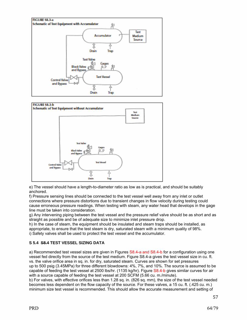
57
e) The vessel should have a length-to-diameter ratio as low as is practical, and should be suitably anchored. f) Pressure sensing lines should be connected to the test vessel well away from any inlet or outlet connections where pressure distortions due to transient changes in flow velocity during testing could cause erroneous pressure readings. When testing with steam, any water head that develops in the gage line must be taken into consideration. g) Any intervening piping between the test vessel and the pressure relief valve should be as short and as straight as possible and be of adequate size to minimize inlet pressure drop. h) In the case of steam, the equipment should be insulated and steam traps should be installed, as appropriate, to ensure that the test steam is dry, saturated steam with a minimum quality of 98%. i) Safety valves shall be used to protect the test vessel and the accumulator. S 5.4 S8.4 TEST VESSEL SIZING DATA a) Recommended test vessel sizes are given in Figures S8.4-a and S8.4-b for a configuration using one vessel fed directly from the source of the test medium. Figure S8.4-a gives the test vessel size in cu. ft. vs. the valve orifice area in sq. in. for dry, saturated steam. Curves are shown for set pressures up to 500 psig (3.45MPa) for three different blowdowns: 4%, 7%, and 10%. The source is assumed to be capable of feeding the test vessel at 2500 lbs/hr. (1135 kg/hr). Figure S8.4-b gives similar curves for air with a source capable of feeding the test vessel at 200 SCFM (5.66 cu. m./minute). b) For valves, with effective orifices less than 1.28 sq. in. (826 sq. mm), the size of the test vessel needed becomes less dependent on the flow capacity of the source. For these valves, a 15 cu. ft. (.425 cu. m.) minimum size test vessel is recommended. This should allow the accurate measurement and setting of
PRD 64/79
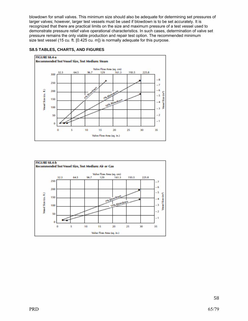
58
blowdown for small valves. This minimum size should also be adequate for determining set pressures of larger valves; however, larger test vessels must be used if blowdown is to be set accurately. It is recognized that there are practical limits on the size and maximum pressure of a test vessel used to demonstrate pressure relief valve operational characteristics. In such cases, determination of valve set pressure remains the only viable production and repair test option. The recommended minimum size test vessel (15 cu. ft. [0.425 cu. m]) is normally adequate for this purpose. S8.5 TABLES, CHARTS, AND FIGURES
PRD 65/79
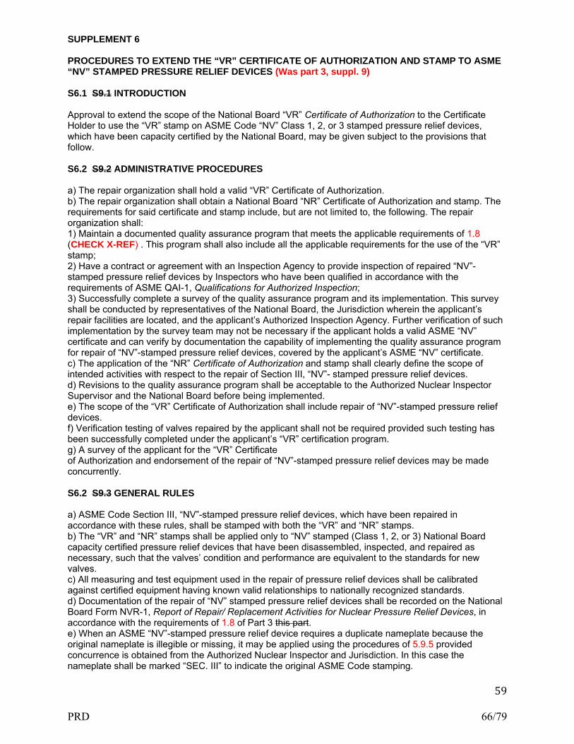
59
SUPPLEMENT 6 PROCEDURES TO EXTEND THE “VR” CERTIFICATE OF AUTHORIZATION AND STAMP TO ASME “NV” STAMPED PRESSURE RELIEF DEVICES (Was part 3, suppl. 9) S6.1 S9.1 INTRODUCTION Approval to extend the scope of the National Board “VR” Certificate of Authorization to the Certificate Holder to use the “VR” stamp on ASME Code “NV” Class 1, 2, or 3 stamped pressure relief devices, which have been capacity certified by the National Board, may be given subject to the provisions that follow. S6.2 S9.2 ADMINISTRATIVE PROCEDURES a) The repair organization shall hold a valid “VR” Certificate of Authorization. b) The repair organization shall obtain a National Board “NR” Certificate of Authorization and stamp. The requirements for said certificate and stamp include, but are not limited to, the following. The repair organization shall: 1) Maintain a documented quality assurance program that meets the applicable requirements of 1.8 (CHECK X-REF) . This program shall also include all the applicable requirements for the use of the “VR” stamp; 2) Have a contract or agreement with an Inspection Agency to provide inspection of repaired “NV”-stamped pressure relief devices by Inspectors who have been qualified in accordance with the requirements of ASME QAI-1, Qualifications for Authorized Inspection; 3) Successfully complete a survey of the quality assurance program and its implementation. This survey shall be conducted by representatives of the National Board, the Jurisdiction wherein the applicant’s repair facilities are located, and the applicant’s Authorized Inspection Agency. Further verification of such implementation by the survey team may not be necessary if the applicant holds a valid ASME “NV” certificate and can verify by documentation the capability of implementing the quality assurance program for repair of “NV”-stamped pressure relief devices, covered by the applicant’s ASME “NV” certificate. c) The application of the “NR” Certificate of Authorization and stamp shall clearly define the scope of intended activities with respect to the repair of Section III, “NV”- stamped pressure relief devices. d) Revisions to the quality assurance program shall be acceptable to the Authorized Nuclear Inspector Supervisor and the National Board before being implemented. e) The scope of the “VR” Certificate of Authorization shall include repair of “NV”-stamped pressure relief devices. f) Verification testing of valves repaired by the applicant shall not be required provided such testing has been successfully completed under the applicant’s “VR” certification program. g) A survey of the applicant for the “VR” Certificate of Authorization and endorsement of the repair of “NV”-stamped pressure relief devices may be made concurrently. S6.2 S9.3 GENERAL RULES a) ASME Code Section III, “NV”-stamped pressure relief devices, which have been repaired in accordance with these rules, shall be stamped with both the “VR” and “NR” stamps. b) The “VR” and “NR” stamps shall be applied only to “NV” stamped (Class 1, 2, or 3) National Board capacity certified pressure relief devices that have been disassembled, inspected, and repaired as necessary, such that the valves’ condition and performance are equivalent to the standards for new valves. c) All measuring and test equipment used in the repair of pressure relief devices shall be calibrated against certified equipment having known valid relationships to nationally recognized standards. d) Documentation of the repair of “NV” stamped pressure relief devices shall be recorded on the National Board Form NVR-1, Report of Repair/ Replacement Activities for Nuclear Pressure Relief Devices, in accordance with the requirements of 1.8 of Part 3 this part. e) When an ASME “NV”-stamped pressure relief device requires a duplicate nameplate because the original nameplate is illegible or missing, it may be applied using the procedures of 5.9.5 provided concurrence is obtained from the Authorized Nuclear Inspector and Jurisdiction. In this case the nameplate shall be marked “SEC. III” to indicate the original ASME Code stamping.
PRD 66/79
60
PRESSURE RELIEF DEVICES – NBIC POLICY FOR METRICATION
PART 4, SECTION 7 SECTION 7
PART 4, SECTION 7 INSTALLATION — NBIC POLICY FOR METRICATION 7.1 GENERAL This policy provides guidance for the use of US customary units and metric units. Throughout the NBIC, metric units are identified and placed in parentheses after the US customary units referenced in the text and associated tables. In Supplement 6, Continued Service and Inspection of DOT Transport Tanks the metric units are shown first with U.S. Customary units shown in parentheses. For each repair or alteration performed, selection of units shall be based on the units used in the original code of construction. For example, items constructed using US customary units shall be repaired or altered using US customary units. The same example applies to items constructed using metric units. Whichever units are selected, those units are to be used consistently throughout each repair or alteration. Consistent use of units includes all aspects of work required for repairs or alterations (i.e. materials, design, procedures, testing, documentation, and stamping, etc.). 7.2 EQUIVALENT RATIONALE The rationale taken to convert metric units and US customary units involves knowing the difference between a soft conversion and a hard conversion. A soft conversion is an exact conversion. A hard conversion is simply performing a soft conversion and then rounding off within a range of intended precision. When values specified in the NBIC are intended to be approximate values, a hard conversion is provided. If an exact value is needed to maintain safety or required based on using good engineering judgment, then a soft conversion will be used. In general, approximate accuracy is acceptable for most repairs or alterations performed using the requirements of the NBIC. Therefore, within the NBIC, metric equivalent units are primarily hard conversions. The following examples are provided for further clarification and understanding of soft conversions versus hard conversions: Example 1: Using 1 in. = 25.4 mm; 12 in. = 304.8 mm (soft conversion) Example 2: Using the above conversion, a hard conversion may be 300 mm or 305 mm depending on the degree of precision needed. 7.3 PROCEDURE FOR CONVERSION The following guidelines shall be used to convert between US customary units and metric units within the text of the NBIC: a) All US customary units will be converted using a soft conversion; b) Soft conversion calculations will be reviewed for accuracy; c) Based on specified value in the NBIC, an appropriate degree of precision shall be identified; d) Once the degree of precision is decided, rounding up or down may be applied to each soft conversion in order to obtain a hard conversion; and e) Use of hard conversion units shall be used consistently throughout the NBIC wherever soft conversions are not required. Note: Care shall be taken to minimize percentage difference between units. 7.4 REFERENCING TABLES The following tables are provided for guidance and convenience when converting between US customary units and metric units. See NBIC Part 1, Tables 7.4-1 through 7.4-8. Temperature shall be converted to within 1°C as shown in NBIC Part 1, Table 7.4-2. Fractions of an inch shall be converted according to NBIC Part 1, Table 7.4-3. Even increments of inches are in even multiples of 25 mm. For example, 40 inches is equivalent to 1000 mm. Intermediate values may be interpolated rather than converting and rounding to the nearest mm. For nominal pipe sizes, the following relationships were used as shown in NBIC Parts 1, 2 or 3, Table 7.4-4. Areas in square inches (in2) were converted to square mm (mm2) and areas in square feet (ft2) were converted
PRD 67/79

61
to square meters (m2). See examples in NBIC Parts 1, 2 or 3 Tables 7.4-5a and 7.4-5b. Volumes in cubic inches (in.3) were converted to cubic mm (mm3) and volumes in cubic feet (ft3) were converted to cubic meters (m3). See examples in NBIC Parts 1, 2 or 3, Tables 7.4-6a and 7.4-6b. Although the pressure should always be in MPa for calculations, there are cases where other units are used in the text. For example, kPa is used for small pressures. Also, rounding was to two significant figures. See examples in Table 7.4-7. (Note that 14.7 psi converts to 101 kPa, while 15 psi converts to 100 kPa. While this may seem at first glance to be an anomaly, it is consistent with the rounding philosophy.) Material properties that are expressed in psi or ksi (e.g., allowable stress, yield and tensile strength, elastic modulus) were generally converted to MPa to three significant figures. See example in NBIC Parts 1, 2 or 3, Table 7.4-8. An often seen metric pressure rating is the expression BAR, one BAR equals 14.5 psi — to convert psi rating to a BAR rating, multiply by 0.069. SECTION 7
TABLE 7.4-3 US Fractions/Metric Equivalents Inches Millimeters 1/32 0.8 3/64 1.2 1/16 1.5 3/32 2.5 1/8 3 5/32 4 3/16 5 7/32 5.5 1/4 6 5/16 8 3/8 10 7/16 11 1/2 13 9/16 14 5/8 16 11/16 17 3/4 19 7/8 22 1 25
TABLE 7.4-1 Soft Conversion Factors (US x Factor = Metric) US Customary Metric Factor in. mm 25.4 ft. m 0.3048 in.2 mm2 645.16 ft.2 m2 0.09290304 in.3 mm3 16,387.064 ft.3 m3 0.02831685 US gal. m3 0.003785412 US gal. liters 3.785412 psi MPa 0.0068948 psi kPa 6.894757 ft-lb J 1.355818 °F °C 5/9 x (°F–32) R K 5/9 lbm kg 0.4535924 lbf N 4.448222 in.-lb N-mm 112.98484 ft.-lb N-m 1.3558181 ksi√in MPa√m 1.0988434 Btu/hr W 0.2930711 lb/ft3 kg/m3 16.018463 in.-wc kPa 0.249089 Note: The actual pressure corresponding to the height of a vertical column of fluid depends on the local gravitational field and the density of the fluid, which in turn depends upon the temperature. This conversion factor is the conventional value adopted by ISO. The conversion assumes a standard gravitational field (gn – 9.80665 N/kg) and a density of water equal to 1,000 kg/m3.
PRD 68/79

62
TABLE 7.4-2 Temperature Equivalents Temperature °F Temperature °C 60 16 70 21 100 38 120 49 350 177 400 204 450 232 800 427 1150 621 SECTION 7
TABLE 7.4-4 Pipe Sizes/Equivalents US CustomaryPractice Metric Practice NPS 1/8 DN 6 NPS 1/4 DN 8 NPS 3/8 DN 10 NPS 1/2 DN 15 NPS 3/4 DN 20 NPS 1 DN 25 NPS 1-1/4 DN 32 NPS 1-1/2 DN 40 NPS 2 DN 50 NPS 2-1/2 DN 65 NPS 3 DN 80 NPS 3-1/2 DN 90 NPS 4 DN 100 NPS 5 DN 125 NPS 6 DN 150 NPS 8 DN 200 NPS 10 DN 250 NPS 12 DN 300 NPS 14 DN 350 NPS 16 DN 400 NPS 18 DN 450 NPS 20 DN 500 NPS 22 DN 550 NPS 24 DN 600 NPS 26 DN 650 NPS 28 DN 700 NPS 30 DN 750 NPS 32 DN 800 NPS 34 DN 850 NPS 36 DN 900 NPS 38 DN 950 NPS 40 DN 1000 NPS 42 DN 1050 NPS 44 DN 1100 NPS 46 DN 1150 NPS 48 DN 1200 NPS 50 DN 1250 NPS 52 DN 1300 NPS 54 DN 1350 NPS 56 DN 1400 NPS 58 DN 1450 NPS 60 DN 1500 Table 7.4-5a Area (US Customary) Area (Metric) 3 in2 650 mm2
6 in2 3,900 mm2
10 in2 6,500 mm2
Table 7.4-5b
PRD 69/79

63
Area (US Customary) Area (Metric) 5 ft2 0.46 mm2
Table 7.4-6a Area (US Customary) Area (Metric) 1 in3 16,000 mm3
6 in3 96,000 mm3
10 in3 160,000 mm3
Table 7.4-6b Area (US Customary) Area (Metric) 5 ft3 0.14 m3
TABLE 7.4-7 Pressure/Equivalents Pressure (US Customary) Pressure (Metric) 0.5 psi 3 kPa 2 psi 15 kPa 3 psi 20 kPa 10 psi 70 kPa 15 psi 100 kPa 30 psi 200 kPa 50 psi 350 kPa 100 psi 700 kPa 150 psi 1.03 MPa 200 psi 1.38 MPa 250 psi 1.72 MPa 300 psi 2.10 MPa 350 psi 2.40 MPa 400 psi 2.76 MPa 500 psi 3.45 MPa 600 psi 4.14 MPa 1,200 psi 8.27 MPa 1,500 psi 10.34 MPa Table 7.4-8 Strength (US Customary) Strength (Metric) 95,000 psi 655 MPa SECTION 8
PRESSURE RELIEF DEVICES – PREPARATION OF TECHNICAL INQUIRIES TO THE NATIONAL BOARD INSPECTION CODE COMMITTEE
PART 4, SECTION 8 SECTION 8
PART 4, SECTION 8 PRESSURE RELIEF DEVICES — PREPARATION OF TECHNICAL INQUIRIES TO THE NATIONAL BOARD INSPECTION CODE COMMITTEE 8.1 INTRODUCTION The NBIC Committee meets regularly to consider written requests for interpretations and revisions to the Code rules. This section provides guidance to Code users for submitting technical inquiries to the Committee. Technical inquires include requests for additions to the Code rules and requests for Code Interpretations, as described below. a) Code Revisions Code revisions are considered to accommodate technological developments, address administrative requirements, or to clarify Code intent. b) Code Interpretations
PRD 70/79

64
Code Interpretations provide clarification of the meaning of existing rules in the Code, and are also presented in question and reply format. Interpretations do not introduce new requirements. In cases where existing Code text does not fully convey the meaning that was intended, and revision of the rules is required to support an Interpretation, an intent Interpretation will be issued and the Code will be revised. As a matter of published policy, the National Board does not approve, certify, or endorse any item, construction, propriety device or activity and, accordingly, inquiries requiring such consideration will be returned. Moreover, the National Board does not act as a consultant on specific engineering problems or on the general application or understanding of the Code rules. Inquiries that do not comply with the provisions of this Section or that do not provide sufficient information for the Committee’s full understanding may result in the request being returned to the inquirer with no action. 8.2 INQUIRY FORMAT Inquiries submitted to the Committee shall include: a) Purpose Specify one of the following: 1) revision of present Code rules; 2) new or additional Code rules; or 3) Code Interpretation. b) Background Provide concisely the information needed for the Committee’s understanding of the inquiry, being sure to include reference to the applicable Code Edition, Addenda, paragraphs, figures, and tables. Provide a copy of the specific referenced portions of the Code.ECTION 8 c) Presentations The inquirer may attend a meeting of the Committee to make a formal presentation or to answer questions from the Committee members with regard to the inquiry. Attendance at a Committee meeting shall be at the expense of the inquirer. The inquirer’s attendance or lack of attendance at a meeting shall not be a basis for acceptance or rejection of the inquiry by the Committee. 8.3 CODE REVISIONS OR ADDITIONS Request for Code revisions or additions shall provide the following: a) Proposed Revisions or Additions For revisions, identify the rules of the Code that require revision and submit a copy of the appropriate rules as they appear in the Code, marked up with the proposed revision. For additions, provide the recommended wording referenced to the existing Code rules. b) Statement of Need Provide a brief explanation of the need for the revision or addition. c) Background Information Provide background information to support the revision or addition, including any data or changes in technology that form the basis for the request that will allow the Committee to adequately evaluate the proposed revision or addition. Sketches, tables, figures, and graphs should be submitted as appropriate. When applicable, identify any pertinent paragraph in the Code that would be affected by the revision or addition and identify paragraphs in the Code that reference the paragraphs that are to be revised or added. 8.4 CODE INTERPRETATIONS Requests for Code Interpretations shall provide the following: a) Inquiry
PRD 71/79

65
Provide a condensed and precise question, omitting superfluous background information and, when possible, composed in such a way that a “yes” or a “no” reply, with brief provisos if needed, is acceptable. The question should be technically and editorially correct. b) Reply Provide a proposed reply that will clearly and concisely answer the inquiry question. Preferably the reply should be “yes” or “no” with brief provisos, if needed. c) Background Information Provide any background information that will assist the Committee in understanding the proposed Inquiry and Reply Requests for Code Interpretations must be limited to an interpretation of the particular requirement in the Code. The Committee cannot consider consulting type requests such as: 1) A review of calculations, design drawings, welding qualifications, or descriptions of equipment or Parts to determine compliance with Code requirements; 2) A request for assistance in performing any Code-prescribed functions relating to, but not limited to, material selection, designs, calculations, fabrication, inspection, pressure testing, or installation; 3) A request seeking the rationale for Code requirements. SECTION 8 8.5 SUBMITTALS Submittals to and responses from the Committee shall meet the following criteria: a) Submittal Inquiries from Code users shall be in English and preferably be submitted in typewritten form; however, legible handwritten inquiries will be considered. They shall include the name, address, telephone number, fax number, and email address, if available, of the inquirer and be mailed to the following address: Secretary, NBIC Committee The National Board of Boiler and Pressure Vessel Inspectors 1055 Crupper Avenue Columbus, OH 43229 As an alternative, inquiries may be submitted via fax or email to: Secretary NBIC Committee Fax: 614.847.1828 Email: [email protected] b) Response The Secretary of the NBIC Committee shall acknowledge receipt of each properly prepared inquiry and shall provide a written response to the Inquirer upon completion of the requested action by the NBIC Committee. PRESSURE RELIEF DEVICES- GLOSSARY OF TERMS PART 4, SECTION 9 PART 4, SECTION 9 PRESSURE RELIEF DEVICES — GLOSSARY OF TERMS 9.1 DEFINITIONS For the purpose of applying the rules of the NBIC, the following terms and definitions shall be used herein as applicable to each Part: Additional terms and definitions specific to DOT Transport Tanks are defined in Part 2, Supplement 6.
PRD 72/79

66
Accumulator — A vessel in which the test medium is stored or accumulated prior to its use for testing. Alteration — A change in the item described on the original Manufacturer’s Data Report which affects the pressure containing capability of the pressure-retaining item. (See Subsection 3.4.3, EXAMPLES OF ALTERATION) Nonphysical changes such as an increase in the maximum allowable working pressure (internal or external), increase in design temperature, or a reduction in minimum temperature of a pressure-retaining item shall be considered an alteration. ANSI — The American National Standards Institute Appliance — A piece of equipment that includes all controls, safety devices, piping, fittings, and vessel(s) within a common frame or enclosure that is listed and labeled by a nationally recognized testing agency for its intended use. ASME Code — The American Society of Mechanical Engineers’ Boiler and Pressure Vessel Code published by that Society, including addenda and Code Cases, approved by the associated ASME Board. Assembler — An organization that purchases or receives from a manufacturer the necessary component parts of valves and assembles, adjusts, tests, seals, and ships safety or safety relief valves at a geographical location, and using facilities other than those used by the manufacturer. Authorized Inspection Agency — New Construction: An Authorized Inspection Agency is one that is accredited by the National Board meeting the qualification and duties of NB-360, Criteria for Acceptance of Authorized Inspection Agencies for New Construction. Inservice: An Authorized Inspection Agency is either: a) a jurisdictional authority as defined in the National Board Constitution; or b) an entity that is accredited by the National Board satisfying the requirements of NB-369, Qualifications and Duties for Authorized Inspection Agencies Performing Inservice Inspection Activities and Qualifications for Inspectors of Boilers and Pressure Vessels; NB-371, Accreditation of Owner-User Inspection Organizations (OUIO) or NB-390, For Federal Inspection Agencies (FIAs) Performing Inservice Inspection Activities. Capacity Certification — The verification by the National Board that a particular valve design or model has successfully completed all capacity testing as required by the ASME Code. Chimney or Stack — A device or means for providing the venting or escape of combustion gases from the operating unit. Confined Space –– Work locations considered “confined” because their configurations hinder the activities of employees who must enter, work in and exit them. A confined space has limited or restricted means for entry or exit, and it is not designed for continuous employee occupancy. Confined spaces include, but are not limited to, underground vaults, tanks, storage bins, manholes, pits, silos, process vessels, and pipelines. Regulatory Organizations often use the term “permit-required confined space” (permit space) to describe a confined space that has one or more of the following characteristics: contains or has the potential to contain a hazardous atmosphere; contains a material that has the potential to engulf an entrant; has walls that converge inward or floors that slope downward and taper into a smaller area which could trap or asphyxiate an entrant; or contains any other recognized safety or health hazard, such as unguarded machinery, exposed live wires, or heat stress. Confined space entry requirements may differ in many locations and the Inspector is cautioned of the need to comply with local or site- specific confined space entry requirements. Conversion — Pressure Relief Devices: The change of a pressure relief valve from one capacity-certified configuration to another by use of manufacturer’s instructions. Units of Measure: Changing the numeric value of a parameter from one system of units to another. Demonstration — Making evident by illustration, expl anation, and completion of tasks documenting evaluation of an applicant’s ability to perform Code activities, including the
PRD 73/79

67
adequacy of the applicant’s quality program, and by a review of the implementation of that program at the address of record and/or work location. Dutchman — Generally limited to tube or pipe cross-section replacement. The work necessary to remove a compromised section of material and replace the section with material meeting the service requirements and installation procedures acceptable to the Inspector. Also recognized as piecing. Examination — In process work denoting the act of performing or completing a task of interrogation of compliance. Visual observations, radiography, liquid penetrant, magnetic particle, and ultrasonic methods are recognized examples of examination techniques. Exit — A doorway, hallway, or similar passage that will allow free, normally upright unencumbered egress from an area. Field — A temporary location, under the control of the Certificate Holder, that is used for repairs and/or alterations to pressure-retaining items at an address different from that shown on the Certificate Holder’s Certificate of Authorization. Forced-Flow Steam Generator — A steam generator with no fixed steamline and waterline. Hydrostatic Test — A liquid pressure test which is conducted using water as the test medium. Inspection — A process of review to ensure engineering design, materials, assembly, examination and testing requirements have been met and are compliant with the Code. Inspector — See National Board Commissioned Inspector and National Board Owner-User Commissioned Inspector. Intervening — Coming between or inserted between, as between the test vessel and the valve being tested. Jurisdiction — A governmental entity with the power, right, or authority to interpret and enforce law, rules, or ordinances pertaining to boilers, pressure vessels, or other pressure-retaining items. It includes National Board member jurisdictions defined as “jurisdictional authorities.” Jurisdictional Authority — A member of the National Board, as defined in the National Board Constitution. Lift Assist Device — A device used to apply an auxiliary load to a pressure relief valve stem or spindle, used to determine the valve set pressure as an alternative to a full pressure test. Liquid Pressure Test — A pressure test using water or other incompressible fluid as a test medium. Manufacturer’s Documentation — The documentation that includes technical information and certification required by the original code of construction. Mechanical Assembly — The work necessary to establish or restore a pressure retaining boundary, under supplementary materials, whereby pressure-retaining capability is established through a mechanical, chemical, or physical interface, as defined under the rules of the NBIC. Mechanical Repair Method — A method of repair, that restores a pressure retaining boundary to a safe and satisfactory operating condition, where the pressure retaining boundary is established by a method other than welding or brazing, as defined under the rules of the NBIC NBIC — The National Board Inspection Code published by The National Board of Boiler and Pressure Vessel Inspectors. “NR” Certificate Holder — An organization in possession of a valid “NR” Certificate of Authorization issued by the National Board. National Board — The National Board of Boiler and Pressure Vessel Inspectors. National Board Commissioned Inspector — An individual who holds a valid and current National Board Commission.
PRD 74/79
68
Nuclear Items — Items constructed in accordance with recognized standards to be used in nuclear power plants or fuel processing facilities. Original Code of Construction — Documents promulgated by recognized national standards writing bodies that contain technical requirements for construction of pressure-retaining items or equivalent to which the pressure retaining item was certified by the original manufacturer. Owner or User — As referenced in lower case letters means any person, firm or corporation legally responsible for the safe operation of any pressure-retaining item. Owner-User Inspection Organization — An owner or user of pressure-retaining items that maintains an established inspection program, whose organization and inspection procedures meet the requirements of the National Board rules and are acceptable to the jurisdiction or jurisdictional authority wherein the owner or user is located. Owner-User Inspector — An individual who holds a valid and current National Board Owner-User Commission. Piecing — A repair method used to remove and replace a portion of piping or tubing material with a suitable material and installation procedure. Pneumatic Test — A pressure test which uses air or another compressible gas as the test medium. Potable Water Heaters — A corrosion resistant appliance that includes the controls and safety devices to supply potable hot water at pressure not exceeding 160 psig (1100 kPa) and temperature not in excess of 210°F (99°C). 1) Fired Storage Water Heater - A potable water heater in which water is heated by electricity, the combustion of solid, liquid, or gaseous fuels and stores water within the same appliance. 2) Indirect Fired Water Heater - A potable water heater in which water is heated by an internal coil or heat exchanger that receives its heat from an external source. Indirect fired water heaters provide water directly to the system or store water within the same appliance. 3) Circulating Water Heater - A potable water heater which furnishes water directly to the system or to a separate storage tank. Circulating water heaters may be either natural or forced flow. Pressure-Retaining Items (PRI) — Any boiler, pressure vessel, piping, or material used for the containment of pressure, either internal or external. The pressure may be obtained from an external source, or by the application of heat from a direct source, or any combination thereof. Pressure Test — A test that is conducted using a fluid (liquid or gas) contained inside a pressure-retaining item. Repair — The work necessary to restore pressure-retaining items to a safe and satisfactory operating condition. Re-ending — A method used to join original code of construction piping or tubing with replacement piping or tubing material for the purpose of restoring a required dimension, configuration or pressure-retaining capacity. Re-rating — See alteration. “R” Certificate Holder — An organization in possession of a valid “R” Certificate of Authorization issued by the National Board. Safety Relief Valves — A safety relief valve is a pressure relief valve characterized by rapid opening or pop action, or by opening in proportion to the increase in pressure over the opening pressure, depending on application. Settings — Those components and accessories required to provide support for the component during operation and during any related maintenance activity. Shop — A permanent location, whose address is shown on the Certificate of Authorization, from which a Certificate Holder controls the repair and/or alteration of pressure-retaining items.
PRD 75/79

69
Testing Laboratory — National Board accepted laboratory that performs functional and capacity tests of pressure relief devices. Transient — An occurrence that is maintained only for a short interval as opposed to a steady state condition. Velocity Distortion — The pressure decrease that occurs when fluid flows past the opening of a pressure sensing line. This is a distortion of the pressure that would be measured under the same conditions for a non or slowly moving fluid. “VR” Certificate Holder — An organization in possession of a valid “VR” Certificate of Authorization issued by the National Board. Water Head — The pressure adjustment that must be taken into account due to the weight of test media (in this case, water) that is 0.433 psi per vertical ft. (10 kPa per m.) added (subtracted) from the gage pressure for each foot the gage is below (above) the point at which the pressure is to be measured. SECTION 10
PRESSURE RELIEF DEVICES – NBIC-APPROVED INTERPRETATIONS
PART 4, SECTION 10
PRD 76/79

PRD 77/79

PRD 78/79

PRD 79/79