pre-service teachers' modeling as a way of thinking in ... teachers' modeling as a way of...
TRANSCRIPT
Paper ID #5867
Pre-service Teachers’ Modeling as a Way of Thinking in Engineering Design
Dr. Matthew D. Lammi, North Carolina State University
Dr. Lammi is an assistant professor in the Department of STEM Education.
Dr. Cameron Denson, North Carolina State University
c©American Society for Engineering Education, 2013
Page 23.972.1
Pre-service Teachers' Modeling as a Way of Thinking in Engineering Design
Matthew D. Lammi, Cameron D. Denson North Carolina State University, Department of STEM Education
Abstract
The purpose of this study was to develop a framework for assessing students working through an engineering design challenge. Using a case study approach to theory building we collected artifacts from a pre-service teachers in a second level Engineering Design Thinking course. The students produced artifacts in the form of conceptual models, graphical models, mathematical models and finally working models. Student-generated mind maps, design journals, final design products and their accompanying documentation, and peer checking procedures were also collected and triangulated with the modeling artifacts for the purpose of this study. The result was a working framework that helps eliminate some of the ambiguity for students producing deliverables for a design challenge and provides the instructor with a practical approach to assessing student work. In addition to offering a new pedagogical approach to engineering design thinking, the following research offers empirical evidence of student cognition as they go through an engineering design process. Finally, we provide definitions and student generated examples of the four modeling artifacts to include; conceptual models, graphical models, mathematical models and working models.
The Need The case for infusing engineering ‒ specifically engineering design ‒ into K-12 settings has
been made by educators and policy makers 1-3 . Yet determining how engineering design will be operationalized in K-12 settings is still a subject of great contention. One pedagogical approach to assist not only the student, but the teacher as well, in engineering design is the focus on modeling and the accompanying artifacts 4 . We proffer that focusing on modeling artifacts is a useful tool for students to demonstrate their engineering design thinking while providing a framework for the assessment of engineering design experiences. This paper will discuss how pre-service teachers approached and engaged in engineering design through the analysis of the modeling artifacts they generated.
This research was pursued to help further understand and elucidate how pre-service engineering education teachers (student-designers) go about engineering design. Specifically, we sought to find out what they did well and where they struggled, what the student-designers understood, and their perception of engineering design when developing modeling artifacts. Although there was the potential for many phenomena to be investigated, we believe an examination of the students’ thoughts and processes around modeling was salient. We also sought to demonstrate the utility of the pedagogical focus on modeling artifacts in engineering design.
Page 23.972.2
Situated in Literature In science, technology, engineering, mathematics (STEM) education at the K-12 level, there
is an established infrastructure for all the sub-disciplines of STEM with the exception of engineering, as it is now only making inroads 2, 5 . Engineering has the potential to integrate the other STEM disciplines as it incorporates mathematical reasoning, scientific inquiry, and technological design. Furthermore, technology and engineering share many concepts in common, primarily design; with both design processes involving modeling and producing artifacts. There are four primary modeling artifacts generated in engineering design: conceptual, graphical, mathematical, and working 1 . It should be noted that the generation of an artifact is not the sole purpose or end being advocated. The process of generating artifacts and the interactions between them is equally if not more important.
In creating learning environments that facilitate the teaching of the engineering design process, it is essential to have rigorous assessment measures of student knowledge 6 . When the goal is to observe the process of thinking or the actual behavior of a performance task, authentic assessment is the key. To achieve this, students must demonstrate knowledge and skills that closely resemble those required in real life in the form of authentic, real-world problem solving 6 . When creating an authentic, real-world client driven problem it is imperative that instructors introduce activities that produce models 7 .
To facilitate this shift from product assessment to process assessment it is important that students communicate their thought process throughout an engineering design problem. To achieve the goal of assessing student thought processes of authentic engineering design problems, students must be able to demonstrate the requirements of design including producing (1) narrative discussion/description, (2) graphical explanation, (3) analytical calculations, and (4) physical creation 3 . Although semantically varying, Wicklein’s 3 assertion proffers that students should be able to demonstrate their understanding of engineering design through the four aforementioned models; conceptual, graphical, mathematical, and physical or working. It is our hypothesis that in order to gain a better understanding of conceptual knowledge and student cognitive abilities, behavior should be demonstrated through the creation of modeling artifacts. According to Jonassen 8 modeling as a tool is very effective in that it helps learners to represent what they know or what they are learning.
Modeling may also provide the key to understanding certain nebulous concepts of engineering and engineering design. This is particularly beneficial when dealing with complex tasks such as understanding systems, a key concept in engineering. One framework suggested for representing and understanding systems is the structure-behavior-function form. Structure-behavior-function or SBF is a concept used to describe the interrelations of systems that focuses on the components (structure), their purpose (function) and the mechanisms that enable them to perform these functions (behavior). Research has shown that engaging students in the building of models is an effective approach to advancing their understanding of SBF 1 . It is clear that the development of models through engineering activities provides a framework for assessing student performance, but more importantly for the learner it provides a pragmatic approach to representing their design thinking, thought processes and advancing certain knowledge acquisition. Katehi et al. 1 further stated that “iterative, purposeful modeling appears to be central
Page 23.972.3
to helping students to a more sophisticated understanding of the salient idea or skill” and this helps students “understand in deeper ways” as “modeling is the most prevalent and challenging form of an activity.”
The germination and expression of the designer’s initial ideas and thoughts is represented as a conceptual model. This is an exploratory exercise characterized by spontaneity and fluid thinking 9 . There is also great flexibility, as decisions have not been made that further constrain the design. Specific details generally do not emerge from this model. This is the artifact of the ideation phase. The artifact is generally a sketch or other loose visualization. There may be multiple conceptual models generated to compare one to the other. Examples include sketches, block diagrams, concept maps, and circuit layouts and may be produced by various media types such as white boards, napkins, and computer software. Although decisions are made at this juncture, a final decision is generally made once the working model is produced.
A graphical model is principally representational. This model is usually shared among the design team in order to solidify the details of the design. The design will take on dimensions and interfaces will be defined. At this point in the design process feasibility is often determined. Therefore, this model contains dimensions, clear specifications, and more accuracy. This model may be termed hard-lined, as it is more concrete in its form 9 . A graphical model is one that is typically ‒ not always ‒ generated with some form of software on a computer. This allows for simulation and testing transitioning into the mathematical model.
One of the principal differences between technological design and engineering design is the generation and analysis of a mathematical model 10 . The mathematical model may be represented early in the design process in tandem with the conceptual model. However, the accuracy, detail, and rigor of the mathematical model will typically improve over time in the design process. “Mathematical modeling and analysis are essential to engineering design” yet, mathematical modeling is often treated as an afterthought or ignored in K-12 education1 . A landscape study of K-12 engineering curricula “did not find any projects or units in which students were instructed to develop and use mathematical models to assist them in designing solutions to problems.” 1 .
Design is a hands-on process that necessitates the use of materials for prototyping and working models 11 . When the design comes to fruition as a palpable artifact, it is a working model. However, the artifact might not be physical or materially tangible, it is nonetheless a working model in that it functions according to the design. This model is also known as a physical model, hands-on, prototype, etc. The term working model is used because an engineer does not always produce a palpable artifact, such as a system or process 12 .
Through a phenomenological study with engineering educators, Asunda and Hill13 were able to generate themes or categories of engineering design. All four of the modeling artifacts were mentioned in the thematic analysis. The terms used were: conceptualizing solutions, graphical output, predictive model, and prototype or working model. However, all four of the models were not put together in one idea or process. Katehi, et al.1 also mentioned the four models but adds
Page 23.972.4
an additional model, “Modeling can take the form of a physical design or a conceptual, graphical, mathematical, or diagrammatic design.”
Table 1. Description of Modeling Artifacts
Artifact Descriptors
Conceptual Model Ideation, brainstorming, flexible, sketches with annotations, alternatives are discussed, emergence of constraints, specifications, and assumptions
Graphical Model Representational, feasibility fleshed out, communicates design, dimensions, can support computer simulations
Mathematical Model Describes how design will work, analysis, testing, informs design, predictive analysis
Working Model Physical prototype, proof of concept, hands-on, can be a virtual model e.g. software program
How We Went about Doing It The purpose of this study was best accomplished by using a case study approach. This
procedure or methodology allows for the in-depth survey of a bounded case, or cases within a case. The context is fully described and salient themes can be explored and explained to represent a phenomenon. According to Creswell 14 , a case study is appropriate when examining a case bounded by time and/or place. More importantly, this approach relies on the gathering of multiple sources of information in an effort to provide an in-depth picture 14 .
The case studied in this research was a group of 11 pre-service teachers in a Technology, Engineering, & Design (TDE) Education program working their way through an engineering design project. The analysis consisted of collecting different forms of physical traces as data. These included student-generated mind maps, design journals, final design products and their accompanying documentation, and peer checking procedures. These data were reviewed as the project moved forward. Themes emerged and were analyzed on an ongoing basis. The different forms of data were compared and measured against each other. As new data were gathered, further insights were gained. Eventually, themes and phenomena emerged and are analyzed and discussed throughout the paper.
What Was the Setting? All of the participants in this research were TDE Education majors; essentially, pre-service
teachers who could become licensed to teach in technology education and graphic communications. Although not all of the student-designers had immediate plans to become teachers upon graduation ‒ non-licensure students ‒ they all were on track to receive an education baccalaureate degree. There were 11 student-designers included in this study.
As part of their major, the student-designers participated in two engineering and design courses. The purpose of these courses was to prepare the pre-service teachers to develop and deliver engineering in and outside their classrooms. The courses introduced not only basic engineering concepts, but the engineering design process as well. The student-designers participated in engineering educational activities such as designing, building, and analyzing
Page 23.972.5

bioreactors, dragsters, model rockets, and assistive technologies. An emphasis was placed on documenting and justifying their design decisions.
The focus of this study was centered around the student-designers’ experiences with the cornerstone design of an assistive technology. The student-designers were tasked with discovering and defining a problem for a disability that can be solved by engineering design. Furthermore, they were to design, build, evaluate, and explain their engineering solution for the assistive technology problem. The student-designers typically worked in groups of three. There was one group of two, but we found the student-designers were most successful in teams of three as it allowed them to accomplish the task by spreading out the work without allowing a group member to coast by. Table 1 is list of the team members and the projects they pursued.
Table 2. Engineering Student-design Groups and Projects
Names Project
Rashida, Aaron, Carlos Ergonomic Grocery Bag Carrier Andrew, Kelly, Curtis One-handed Jar Opener DeShawn, Glenn, Eric Golf Ball and Tee Placer Paul & Kaydron Assisted Chair Lift Note: All names are pseudonyms
What Did We Find? The student-designers were familiar with the idea of engineering design, but were not
afforded the opportunity to engage in a complete engineering design activity prior to the cornerstone design project. Figure 1 contains two concept maps of engineering design generated by student-designers at the start of the course.
Page 23.972.6

Figure 1. Student-designers’ Concept Maps of Engineering Design. Note: These concept maps were generated at the beginning of the course and represent the perception of the engineering design process being a linear procedure.
These concept maps suggest that many of the student-designers misunderstood the engineering design process to be linear, with steps to be followed from start to finish. Additionally, there was a common set of concepts generated by most of the students including: problem definition, brainstorming, research, testing, and analysis.
Modeling Artifacts The four design groups were all given the same problem that follows below:
Discover and define a problem for a disability that can be solved by engineering design. Design, build, evaluate, and explain your engineering solution for the assistive technology problem. Prepare justification and documentation for your project. The design can either be completely novel or build upon existing technologies. You will produce a problem statement and four modeling artifacts: conceptual, graphical, mathematical, and working.
The student-designers were instructed to discover and formulate a problem on their own. The process of formulating a problem is a noteworthy topic that deserves a separate study. After delivering a problem statement, the student-designers were instructed to produce four modeling artifacts and to keep detailed documentation of their processes. The instructor gave feedback to the students from their weekly status updates and personal coaching. Each modeling artifact will be discussed separately below.
Page 23.972.7
Conceptual Model Although the students were not familiar with the term conceptual model, they easily went
about producing them. The majority of the students produced a conceptual model as a sketch, with some of the artifacts containing annotations. A conceptual model is not limited to a sketch or a series of sketches from a brainstorm. Yet, there were students who presented their conceptual models with minimal effort, compromising of a simple sketch or two. What was lacking was detail and justification. Although a conceptual model does not require exact specifications and high detail, small notes and explanations can aid in the design process by spurring creativity and facilitating communication.
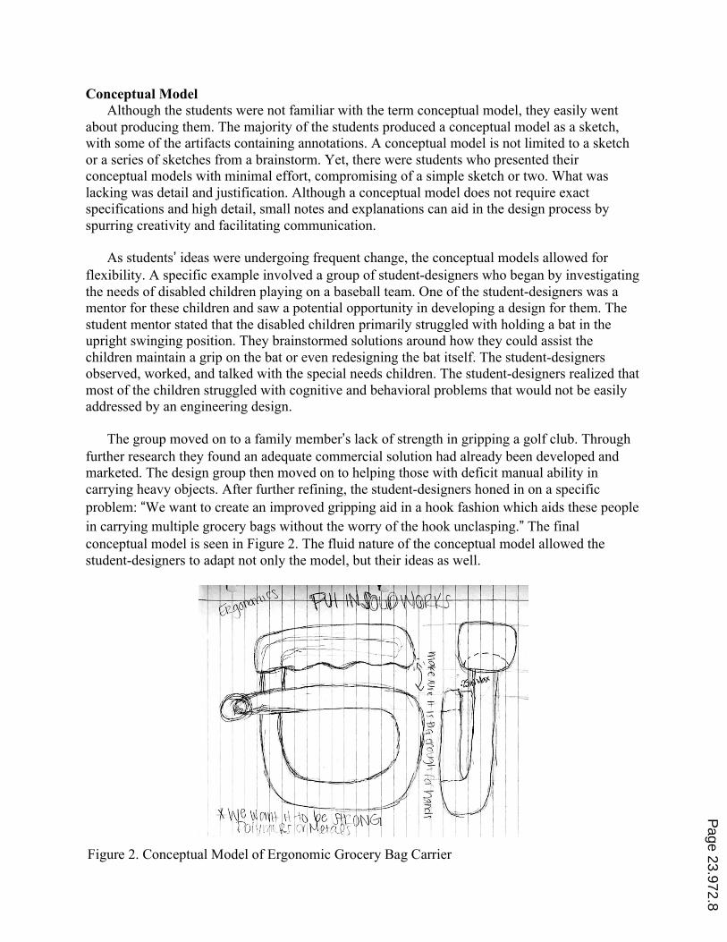
As students’ ideas were undergoing frequent change, the conceptual models allowed for flexibility. A specific example involved a group of student-designers who began by investigating the needs of disabled children playing on a baseball team. One of the student-designers was a mentor for these children and saw a potential opportunity in developing a design for them. The student mentor stated that the disabled children primarily struggled with holding a bat in the upright swinging position. They brainstormed solutions around how they could assist the children maintain a grip on the bat or even redesigning the bat itself. The student-designers observed, worked, and talked with the special needs children. The student-designers realized that most of the children struggled with cognitive and behavioral problems that would not be easily addressed by an engineering design.
The group moved on to a family member’s lack of strength in gripping a golf club. Through further research they found an adequate commercial solution had already been developed and marketed. The design group then moved on to helping those with deficit manual ability in carrying heavy objects. After further refining, the student-designers honed in on a specific problem: “We want to create an improved gripping aid in a hook fashion which aids these people in carrying multiple grocery bags without the worry of the hook unclasping.” The final conceptual model is seen in Figure 2. The fluid nature of the conceptual model allowed the student-designers to adapt not only the model, but their ideas as well.
Figure 2. Conceptual Model of Ergonomic Grocery Bag Carrier
Page 23.972.8
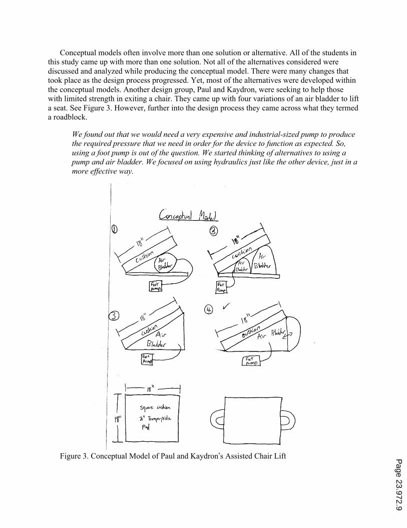
Conceptual models often involve more than one solution or alternative. All of the students in this study came up with more than one solution. Not all of the alternatives considered were discussed and analyzed while producing the conceptual model. There were many changes that took place as the design process progressed. Yet, most of the alternatives were developed within the conceptual models. Another design group, Paul and Kaydron, were seeking to help those with limited strength in exiting a chair. They came up with four variations of an air bladder to lift a seat. See Figure 3. However, further into the design process they came across what they termed a roadblock.
We found out that we would need a very expensive and industrial-sized pump to produce the required pressure that we need in order for the device to function as expected. So, using a foot pump is out of the question. We started thinking of alternatives to using a pump and air bladder. We focused on using hydraulics just like the other device, just in a more effective way.
Figure 3. Conceptual Model of Paul and Kaydron’s Assisted Chair Lift Page 23.972.9
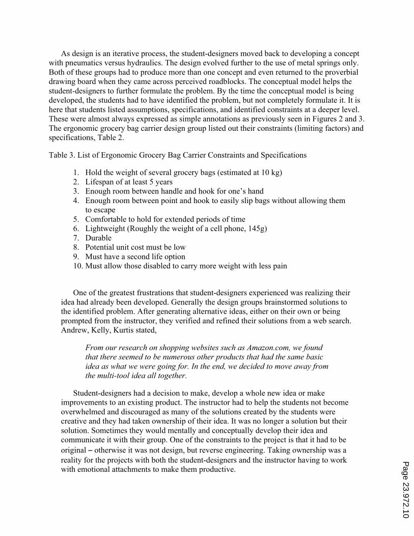
As design is an iterative process, the student-designers moved back to developing a concept with pneumatics versus hydraulics. The design evolved further to the use of metal springs only. Both of these groups had to produce more than one concept and even returned to the proverbial drawing board when they came across perceived roadblocks. The conceptual model helps the student-designers to further formulate the problem. By the time the conceptual model is being developed, the students had to have identified the problem, but not completely formulate it. It is here that students listed assumptions, specifications, and identified constraints at a deeper level. These were almost always expressed as simple annotations as previously seen in Figures 2 and 3. The ergonomic grocery bag carrier design group listed out their constraints (limiting factors) and specifications, Table 2.
Table 3. List of Ergonomic Grocery Bag Carrier Constraints and Specifications
1. Hold the weight of several grocery bags (estimated at 10 kg) 2. Lifespan of at least 5 years 3. Enough room between handle and hook for one’s hand 4. Enough room between point and hook to easily slip bags without allowing them
to escape 5. Comfortable to hold for extended periods of time 6. Lightweight (Roughly the weight of a cell phone, 145g) 7. Durable 8. Potential unit cost must be low 9. Must have a second life option 10. Must allow those disabled to carry more weight with less pain
One of the greatest frustrations that student-designers experienced was realizing their idea had already been developed. Generally the design groups brainstormed solutions to the identified problem. After generating alternative ideas, either on their own or being prompted from the instructor, they verified and refined their solutions from a web search. Andrew, Kelly, Kurtis stated,
From our research on shopping websites such as Amazon.com, we found that there seemed to be numerous other products that had the same basic idea as what we were going for. In the end, we decided to move away from the multi-tool idea all together.
Student-designers had a decision to make, develop a whole new idea or make improvements to an existing product. The instructor had to help the students not become overwhelmed and discouraged as many of the solutions created by the students were creative and they had taken ownership of their idea. It was no longer a solution but their solution. Sometimes they would mentally and conceptually develop their idea and communicate it with their group. One of the constraints to the project is that it had to be original ‒ otherwise it was not design, but reverse engineering. Taking ownership was a reality for the projects with both the student-designers and the instructor having to work with emotional attachments to make them productive.
Page 23.972.10
Sketching is an important part of engineering design, especially in the development of a conceptual model 15 . Although there was a disparity in drawing ability, each student-design group produced multiple drawings. A similar finding was found with novice high school student-designer as well 16 .
Graphical Model One of the roles of the graphical model was to encourage the student-designers to
flesh out and refine their conceptual design. Further design details, specifications, and constraints emerged; as well as any obstacles or necessary changes. Paul and Kaydron reflected on their project and stated, “Teaching your students that your design is not going to come out exactly the way you planned is crucial. Major design changes are necessary most of the time and more than likely you will have to make them.” Student-designers who allowed for flexibility in their design process developed the most successful projects; as they did not become fixated and limited to one idea only.
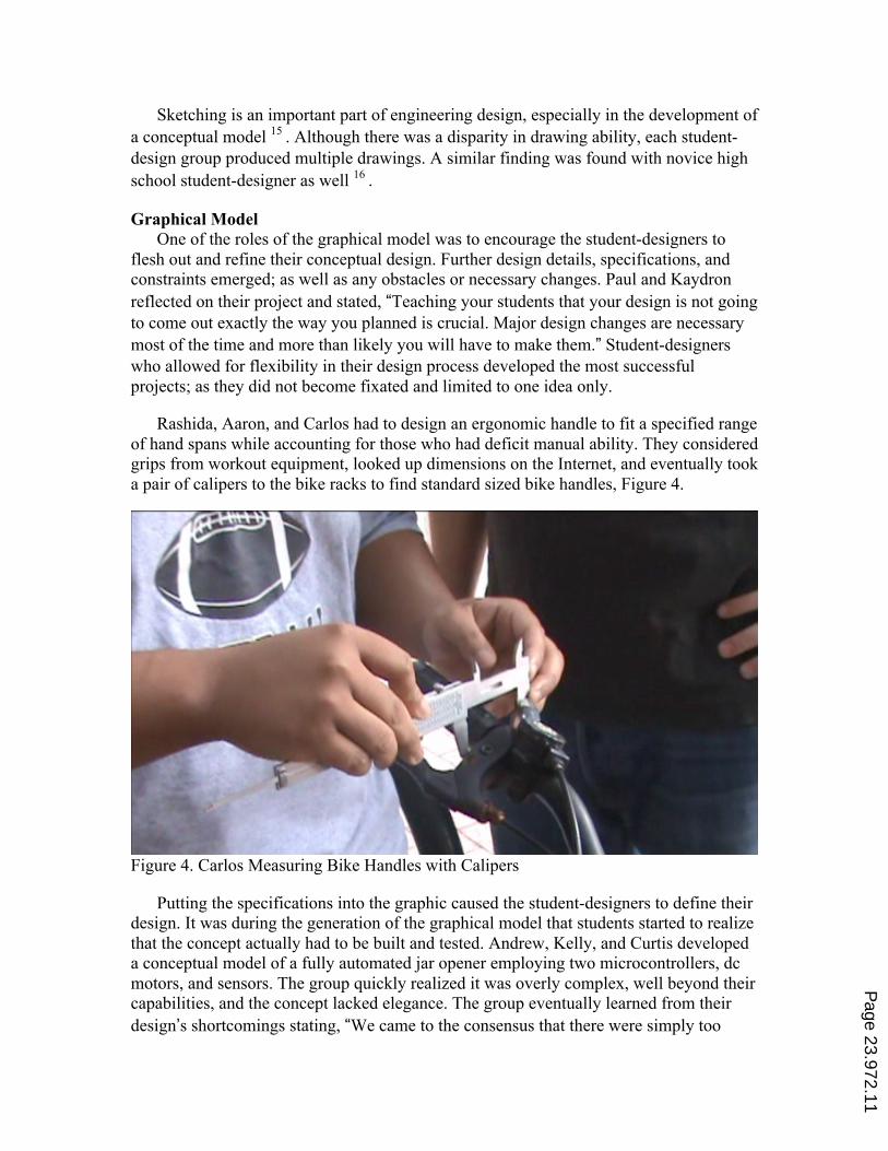
Rashida, Aaron, and Carlos had to design an ergonomic handle to fit a specified range of hand spans while accounting for those who had deficit manual ability. They considered grips from workout equipment, looked up dimensions on the Internet, and eventually took a pair of calipers to the bike racks to find standard sized bike handles, Figure 4.
Figure 4. Carlos Measuring Bike Handles with Calipers
Putting the specifications into the graphic caused the student-designers to define their design. It was during the generation of the graphical model that students started to realize that the concept actually had to be built and tested. Andrew, Kelly, and Curtis developed a conceptual model of a fully automated jar opener employing two microcontrollers, dc motors, and sensors. The group quickly realized it was overly complex, well beyond their capabilities, and the concept lacked elegance. The group eventually learned from their design’s shortcomings stating, “We came to the consensus that there were simply too
Page 23.972.11
many potential points of failure associated with our design and moved on to our next idea.” Their final design ended up being one simple device completely free of moving parts. As the student-designers had to justify each design decision, balancing the trade-offs between functionality and simplicity, they exercised deeper metacognition.
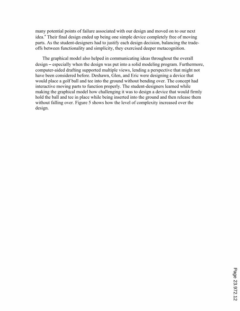
The graphical model also helped in communicating ideas throughout the overall design ‒ especially when the design was put into a solid modeling program. Furthermore, computer-aided drafting supported multiple views, lending a perspective that might not have been considered before. Deshawn, Glen, and Eric were designing a device that would place a golf ball and tee into the ground without bending over. The concept had interactive moving parts to function properly. The student-designers learned while making the graphical model how challenging it was to design a device that would firmly hold the ball and tee in place while being inserted into the ground and then release them without falling over. Figure 5 shows how the level of complexity increased over the design.
Page 23.972.12
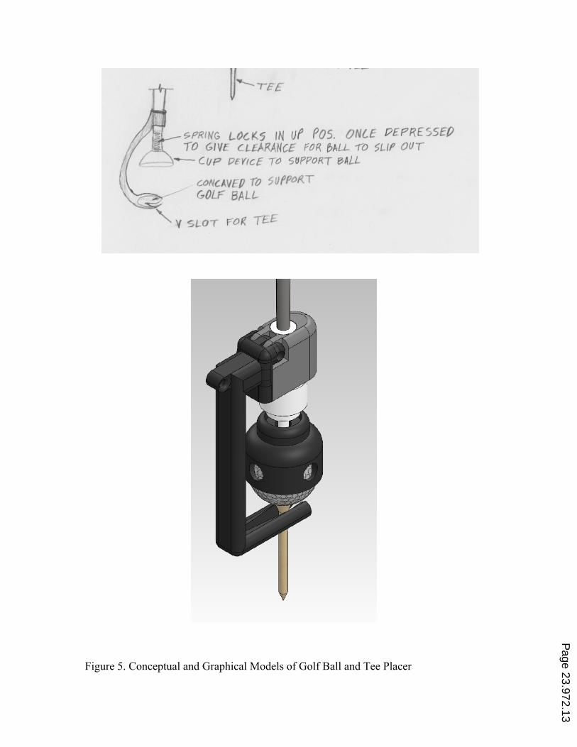
Figure 5. Conceptual and Graphical Models of Golf Ball and Tee Placer
Page 23.972.13
Mathematical Model A mathematical model can be viewed as a mathematical construct that helps us
understand behaviors of interest and real world systems. Mathematical models should be viewed as idealization of the real world and though they help predict behavior they should not be viewed as completely accurate 17 . The mathematical models were the most difficult models for the student-designers to produce. Instead, many of the student-designers wanted to jump straight to a working model. All of the student-designers had multiple courses where they developed and produced working models and prototypes. There was already a high comfort level in producing something tangible. However, creating and applying an abstract mathematical model to their designs was a relatively new practice.
The student-designers had done math in their previous projects, but had not applied it. Furthermore, many of them did not see how a mathematical model could be used to improve a design. If they did see how it could help, they often felt that they were not capable of applying math to their design. One of the failed perspectives of the student-designers was viewing math as computations, rather than as a form of problem solving. In lieu of using the mathematical model to make a better design, most student-designers were not able to grasps the purpose of a mathematical model. Admittedly, most of the student-designers did not see the point of a mathematical model at first, but rather saw it as a “step” in a procedure.
The student-design groups wanted to move forward with a design decision without giving justification for their designs and decisions. An unjustified design often resulted in a flawed or failed design. Glen, DeShawn, and Eric were creating a tool to be used on the golf course that would allow the golfer to place a ball and tee into the ground without having to bend over. There were three weeks allocated to formulating a problem, but this group came up with a solution by the second class meeting. Glen insisted that the problem was understood and that a prototype had to be built to understand the problem further. His group mates were not settled on the idea, but they moved forward with building the working model. They quickly realized that the initial design had many flaws that were not fleshed out. The device used a string to actuate a lever that held the ball and tee. Once the tee was set, the lever was supposed to leave the ball and tee in place. See Figure 5 above. However, the lever either did not release the tee or it knocked over the ball when being removed. The group built another prototype, but found “several more issues with getting the golf tee to stay straight and go into the ground.”
Page 23.972.14
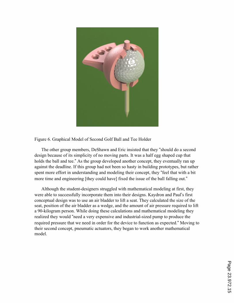
Figure 6. Graphical Model of Second Golf Ball and Tee Holder
The other group members, DeShawn and Eric insisted that they “should do a second design because of its simplicity of no moving parts. It was a half egg shaped cup that holds the ball and tee.” As the group developed another concept, they eventually ran up against the deadline. If this group had not been so hasty in building prototypes, but rather spent more effort in understanding and modeling their concept, they “feel that with a bit more time and engineering [they could have] fixed the issue of the ball falling out.”
Although the student-designers struggled with mathematical modeling at first, they were able to successfully incorporate them into their designs. Kaydron and Paul’s first conceptual design was to use an air bladder to lift a seat. They calculated the size of the seat, position of the air bladder as a wedge, and the amount of air pressure required to lift a 90-kilogram person. While doing these calculations and mathematical modeling they realized they would “need a very expensive and industrial-sized pump to produce the required pressure that we need in order for the device to function as expected.” Moving to their second concept, pneumatic actuators, they began to work another mathematical model.
Page 23.972.15
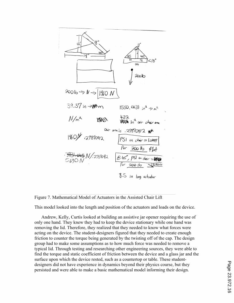
Figure 7. Mathematical Model of Actuators in the Assisted Chair Lift
This model looked into the length and position of the actuators and loads on the device.
Andrew, Kelly, Curtis looked at building an assistive jar opener requiring the use of only one hand. They knew they had to keep the device stationary while one hand was removing the lid. Therefore, they realized that they needed to know what forces were acting on the device. The student-designers figured that they needed to create enough friction to counter the torque being generated by the twisting off of the cap. The design group had to make some assumptions as to how much force was needed to remove a typical lid. Through testing and researching other engineering sources, they were able to find the torque and static coefficient of friction between the device and a glass jar and the surface upon which the device rested, such as a countertop or table. These student-designers did not have experience in dynamics beyond their physics course, but they persisted and were able to make a basic mathematical model informing their design.
Page 23.972.16
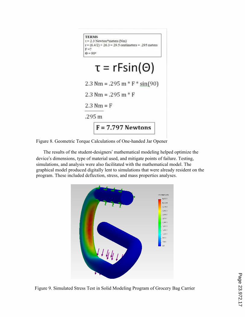
Figure 8. Geometric Torque Calculations of One-handed Jar Opener
The results of the student-designers’ mathematical modeling helped optimize the device’s dimensions, type of material used, and mitigate points of failure. Testing, simulations, and analysis were also facilitated with the mathematical model. The graphical model produced digitally lent to simulations that were already resident on the program. These included deflection, stress, and mass properties analyses.
Figure 9. Simulated Stress Test in Solid Modeling Program of Grocery Bag Carrier
Page 23.972.17
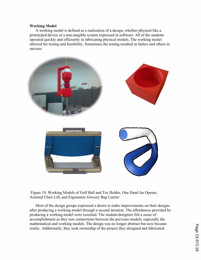
Working Model A working model is defined as a realization of a design, whether physical like a
prototyped device or a non-tangible system expressed in software. All of the students operated quickly and efficiently in fabricating physical models. The working model allowed for testing and feasibility. Sometimes the testing resulted in failure and others in success.
Figure 10. Working Models of Golf Ball and Tee Holder, One Hand Jar Opener, Assisted Chair Lift, and Ergonomic Grocery Bag Carrier
Most of the design groups expressed a desire to make improvements on their designs after producing a working model through a second iteration. The affordances provided by producing a working model were essential. The student-designers felt a sense of accomplishment as they saw connections between the previous models, especially the mathematical and working models. The design was no longer abstract but now became reality. Additionally, they took ownership of the project they designed and fabricated.
Page 23.972.18
Many of the frustrations experienced while producing the mathematical model were allayed when a better working model was produced.
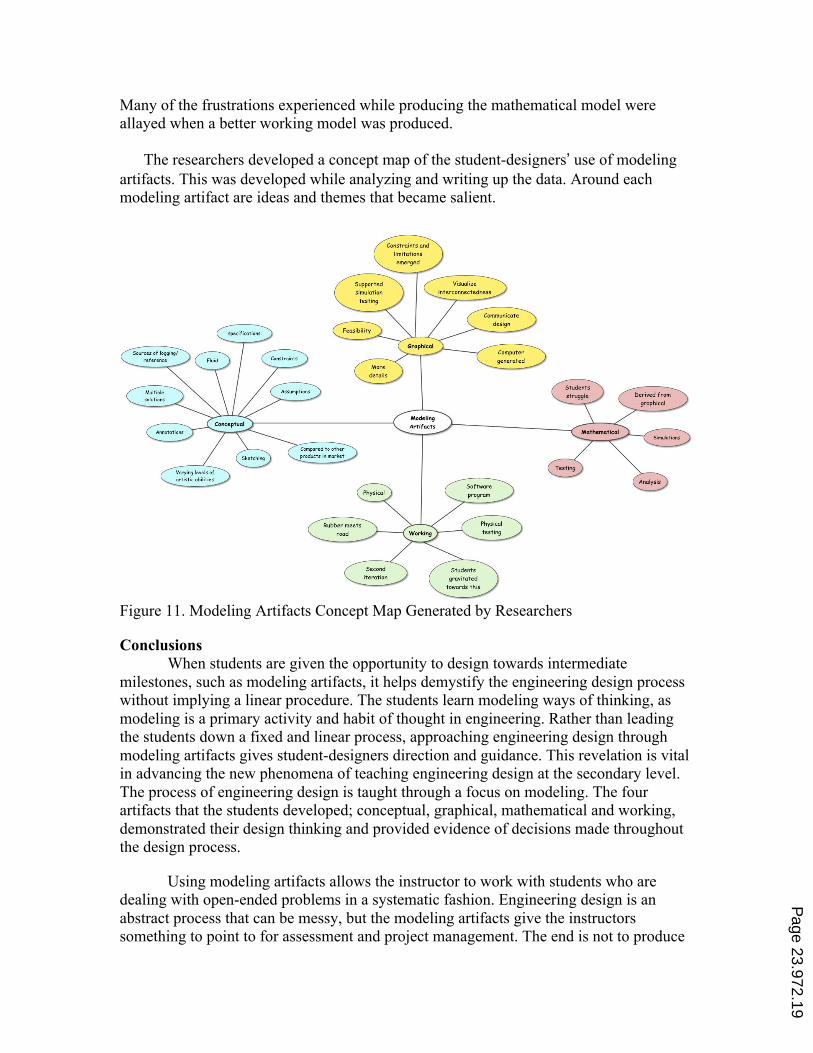
The researchers developed a concept map of the student-designers’ use of modeling artifacts. This was developed while analyzing and writing up the data. Around each modeling artifact are ideas and themes that became salient.
Figure 11. Modeling Artifacts Concept Map Generated by Researchers
Conclusions When students are given the opportunity to design towards intermediate
milestones, such as modeling artifacts, it helps demystify the engineering design process without implying a linear procedure. The students learn modeling ways of thinking, as modeling is a primary activity and habit of thought in engineering. Rather than leading the students down a fixed and linear process, approaching engineering design through modeling artifacts gives student-designers direction and guidance. This revelation is vital in advancing the new phenomena of teaching engineering design at the secondary level. The process of engineering design is taught through a focus on modeling. The four artifacts that the students developed; conceptual, graphical, mathematical and working, demonstrated their design thinking and provided evidence of decisions made throughout the design process.
Using modeling artifacts allows the instructor to work with students who are dealing with open-ended problems in a systematic fashion. Engineering design is an abstract process that can be messy, but the modeling artifacts give the instructors something to point to for assessment and project management. The end is not to produce
Page 23.972.19
modeling artifacts, but rather have the student-designers gain new habits of mind through immersion in the engineering design process. One of the most contentious areas of concern for engineering design in high school settings is the issue of assessment. Without developing adequate measures to assess students’ design experiences it would prove to be an arduous task to introduce authentic real-world problems to high school students. Modeling artifacts counters many of these issues by providing a practical approach for students to demonstrate their design thinking and decision making processes. Although many students struggled with the concept of mathematical modeling, their experiences provided evidence that using modeling artifacts as deliverables helped students understand difficult concepts and offered a framework for assessing students’ designs. Pedagogical advantages that modeling artifacts offer teachers and learners, include providing concrete examples of design thinking of a process that is very abstract. Modeling artifacts provide educators and researchers with a window into student cognition when engaged in engineering design experiences.
References 1. Katehi, L.; Pearson, G.; Feder, M., Engineering in K - 12 education:
Understanding the status and improving the prospects. The National Academies Press: Washington, DC, 2009.
2. National Research Council, A framework for K-12 science education: Practices, crosscutting concepts, and core ideas. The National Academies Press: Washington D.C., 2012.
3. Wicklein, R. C., Five good reasons for engineering design as the focus for technology education. The Technology Teacher 2006, 65, (7), 25-29.
4. Young, R. An engineering modeling approach to problem solving using mathematics; Project MINDSET - North Carolina State University: Raleigh, North Carolina, 2012.
5. International Technology and Engineering Education Association, Standards for technological literacy: Content for the study of technology. Author: Reston, VA, 2000.
6. Bailey, R.; Szabo, Z., Assessing engineering design knowledge. International Journal of Engineering Education 2005, 22, (3), 508-518.
7. Diefes-Dux, H.; Moore, T.; Zawojewski, J.; Imbrie, P.; Follman, D., A framework for posing open-ended engineering problems: Model-eliciting activities. In Frontiers in Education, Savannah, Georgia, 2004.
8. Jonassen, D., Toward a design theory of problem solving. Educational Technology Research and Development 2000, 48, (4), 63-85. P
age 23.972.20
9. MacDonald, D.; Gustafson, B. J.; Gentilini, S., Enhancing children's drawing in design technology planning and making. Research in Science & Technological Education 2007, 25, (1), 59-75.
10. Hailey, C. E.; Erekson, T. L.; Becker, K. H.; Thomas, M., National Center for Engineering and Technology Education. The Technology Teacher 2005, 64, (5), 23-26.
11. Apedoe, X.; Reynolds, B.; Ellefson, M.; Schunn, C., Bringing engineering design into high school science classrooms: The heating/cooling unit. Journal of Science Education and Technology 2008, 17, (5), 454-465.
12. ABET ABET 2009 Requirements. http://www.abet.org/Linked DocumentsUPDATE/Criteria and PP/E001 09-10 EAC Criteria 12-01-08.pdf
13. Asunda, P. A.; Hill, R. B., Critical features of engineering design in technology education. Journal of Industrial Teacher Education 2007, 44, (1), 25-48.
14. Creswell, J. W., Qualitative inquiry and research design: Choosing among five approaches. Sage: Thousand Oaks, CA, 2012.
15. Yang, M. C., Concept generation and sketching: Correlations with design outcome. In ASME Design Engineering Technical Conference 2003, American Society of Mechanical Engineers: Chicago, IL, 2003; pp 1-6.
16. Lammi, M.; Branoff, T., High school students’ habits of mind and action in engineering design. In ASEE Annual Conference, San Antonio, TX, 2012; pp 1-11.
17. Giordano, F.; Fox, W.; Horton, S.; Weir, M., A first course in mathematical modeling. 4 ed.; Brooks/Cole Cengage Learning: Belmont, CA, 2009.
Page 23.972.21