precont ps4sm
TRANSCRIPT

07.17Technical manual
ApplicationsGeneral applications in• Machinery and plant engineering• Air-conditioning and refrigeration plant engineering• Hydraulic and pneumatic systems• Process industry• Environmental technology
Precont PS4SM
Pressure switch for general applicationsMonitoring of absolute or relative pressure in gases, vapors, liquids and dust
Main featuresWide range of applications• Finely graded measuring ranges from 400 mbar up to 1000
bar• Wide process temperature range –40°C to +125°C• Wide variety of process connections • High protection class IP65 / IP67• Wide environmental temperature range –40°C to +85°C
Metallic front-flush or internal diaphragm
High accuracy – characteristic deviation ≤ 0,5% of measuring range
Integrated evaluation electronic• Digital display, function LED’s, keyboard• 2x PNP switch output• 1x current output 4…20mA• Connector plug M12
High operating comfort• Enclosure and display rotatable for optimal operability in
each installation position• Robust high brightness LED display for best readability• 3-key operation without additional assistance with tactile
feedback

ACS-CONTROL-SYSTEM GmbH l Lauterbachstr. 57 l D-84307 Eggenfelden l www.acs-controlsystem.de l [email protected]
You have purchased a high-grade and modern measuring device of ACS-CONTROL-SYSTEM GmbH.
We want to give thanks for your purchase and for your confidence to us.
The actual technical manual includes instructions for installation, electrical connection and inauguration, as well as the technical data of the device.
Modifications, that answer the purpose of the technical progress, are reserved byACS-CONTROL-SYSTEM GmbH without prior notice.
If a question occurs, that can‘t be answered by the listed informations, please call on our technicians team in Eggenfelden Tel: +49 8721/ 9668-0 or [email protected]
All rights reserved

ACS-CONTROL-SYSTEM GmbH l Lauterbachstr. 57 l D-84307 Eggenfelden l www.acs-controlsystem.de l [email protected] 3
Index1 System description . . . . . . . . . . . . . . . . . . . . . . . . . . . . . . . . . . . . . . . . . . . . . . . . 4
1.1 Intended use ................................................... 41.2 Field of application ........................................... 41.3 System components ......................................... 51.4 Function ......................................................... 5
2 Safety notes . . . . . . . . . . . . . . . . . . . . . . . . . . . . . . . . . . . . . . . . . . . . . . . . . . . . . 62.1 Operational safety ............................................ 62.2 Installation, connection, commissioning, operation 6
3 Installation . . . . . . . . . . . . . . . . . . . . . . . . . . . . . . . . . . . . . . . . . . . . . . . . . . . . . . 73.1 Installation place ............................................. 73.2 Process and environmental temperature ............. 73.3 Installation notes ............................................. 73.4 Air pressure compensation ................................ 7
4 Electrical connection . . . . . . . . . . . . . . . . . . . . . . . . . . . . . . . . . . . . . . . . . . . . . . 84.1 Potential equalization - earthing ......................... 84.2 Connection cable ............................................. 84.3 Supply voltage ................................................ 84.4 Switch output .................................................. 84.5 Analogue output .............................................. 84.6 Connection scheme .......................................... 9
5 Operation . . . . . . . . . . . . . . . . . . . . . . . . . . . . . . . . . . . . . . . . . . . . . . . . . . . . . . 115.1 Operation and display parts ............................... 115.2 Function modes ............................................... 125.3 Switch output S1 / S2 ...................................... 125.4 Current output ................................................ 145.5 Menu structure ................................................ 155.6 Parameter overview ......................................... 185.7 Error indication at operation .............................. 22
6 Service . . . . . . . . . . . . . . . . . . . . . . . . . . . . . . . . . . . . . . . . . . . . . . . . . . . . . . . . 236.1 Maintenance .................................................... 236.2 Dismounting.................................................... 236.3 Repair ............................................................ 236.4 Return ............................................................ 236.5 Disposal ......................................................... 23
7 Technical Data . . . . . . . . . . . . . . . . . . . . . . . . . . . . . . . . . . . . . . . . . . . . . . . . . . 247.1 Auxiliary power supply ...................................... 247.2 Output ........................................................... 247.3 Measuring accuracy .......................................... 247.4 Mounting position ............................................ 257.5 Process conditions ............................................ 257.6 Environmental conditions .................................. 257.7 Materials - process wetted ................................ 267.8 Materials - not process wetted ........................... 26
8 Dimension drawings . . . . . . . . . . . . . . . . . . . . . . . . . . . . . . . . . . . . . . . . . . . . . . 278.1 Terminal enclosure ........................................... 278.2 Temperature decoupler ..................................... 278.3 Process connection ........................................... 28
9 Ordering information . . . . . . . . . . . . . . . . . . . . . . . . . . . . . . . . . . . . . . . . . . . . . 309.1 Order code ...................................................... 309.2 Additional options ............................................ 319.3 Accessories ..................................................... 31

ACS-CONTROL-SYSTEM GmbH l Lauterbachstr. 57 l D-84307 Eggenfelden l www.acs-controlsystem.de l [email protected]
1 System description
1 .1 Intended useThe device is an electronic pressure switch for monitoring, control as well as continuous measurement of pressures in gases, vapors, liquids and dusts.
The operational reliability of the device is ensured only at the intended use.
1 .2 Field of applicationDue to the device construction with
• Measuring ranges from -1 bar to 1000 bar, gauge• Measuring ranges from 0 bar to 1000 bar, absolute• Measuring spans from 400 mbar to 1000 bar• Process temperatures from –40°C to +125°C• Process material CrNi-steel
as well as the availability of industrial standard process connections like• thread ISO 228-1, EN 837 manometer• thread ISO 228-1, front-flush
the device is especially suitable for the use for• Machinery and plant engineering• Air-conditioning and refrigeration plant engineering• Hydraulic and pneumatic systems• Process industry• Environmental technology• Facility and building automation
The device is suitable for demanding measuring requirements.
Due to its high accuracy and the high flexibility of configuration, the device can be suited a wide variety of applications.
The front-flush diaphragm has been specifically designed for the measurement of viscous, paste-like, adhesive, crystallizing, particle-laden and contaminated media, which would clog the pressure channel of conventional process connections.
The robust design and the high-quality workmanship turns the device into a very high quality product, which even the most adverse environmental conditions cannot affect, whether the lowest temperatures when used outdoors, extreme shock and vibration or aggressive media.
A captive laser marking of the type label ensures the identifiability throughout the entire lifetime of the device.Obviously is the optional marking of a measurement point designation resp. TAG, a customer label or of a neutral type label, of course also per laser marking.
A LABS-free resp. silicone-free version, a factory calibration with calibration certificate and a customer specific configuration resp. preset is also optionally available like factory certifications for drink water resp. food suitability.
Customer specific special versions can be realized on request, e.g.• software adaption (menu navigation, special functions, etc.),• changed terminal assignment resp. connector orientation,• design adaption of the user surface,• extended process temperature range up to 400°C• special designs for the process connection• other process materials• other fill fluids• special adjustment

ACS-CONTROL-SYSTEM GmbH l Lauterbachstr. 57 l D-84307 Eggenfelden l www.acs-controlsystem.de l [email protected] 5
1 .3 System componentsThe device consists on the components:
• Process connection, for installation into the wall of the container or of the pipeline.• Process diaphragm as junction point in direct contact with the applied medium, fill fluid for the
pressure transfer (only measuring ranges ≤ 25 bar resp. front-flush diaphragm) and pressure measuring sensor.
• Temperature decoupler, for decoupling of the terminal enclosure from high process temperatures.
• Terminal enclosure, rotatable by 300°, for protection of the integrated signal processing electronic and for the electrical connection.
The components cannot be separated by the user.
1 .4 Function1 .4 .1 Measuring principle
At process connections with internal metallic diaphragm and measuring ranges ≥ 40 bar, the system pressure is directly applied to the pressure measuring sensor. A dry pressure measuring sensor is used, without using a fill fluid.
At process connections with front-flush metallic diaphragm resp. at measuring ranges ≤ 25 bar the system pressure is transferred by a fill fluid from the diaphragm to the pressure measuring sensor, which is positioned behind.
The pressure dependent deflection of the diaphragm is transferred to a measuring bridge and causes there a change of the bridge output voltage.
1 .4 .2 Signal processingThe pressure signal is converted by the pressure measuring sensor into an electrical signal and processed by the integrated evaluation electronic according to the respective preferences:
• The measuring value is monitored by two PNP switch outputs for exceedance of limit values.• The measuring value is converted into a continuous current signal 4...20mA.• The measuring value is displayed at the robust high brightness LED display.• Several function LED’s signal the device state.• All settings can be changed comfortable and easy by a 3-key operation without additional
assistance with tactile feedback.
The device includes numerous functions to the adaption to nearly each measuring task:• Adjustable measuring range down to 25% of nominal measuring span• Integrated unit conversion bar – kPa – MPa – PSI• Peak value memory minimum – maximum• Error memory for fast failure analysis• Hysteresis or window function, time delay and working principle of the switch outputs• Error indication function to switch output, current output and display• Simulation of the switch outputs and the current output

ACS-CONTROL-SYSTEM GmbH l Lauterbachstr. 57 l D-84307 Eggenfelden l www.acs-controlsystem.de l [email protected]
2 Safety notes2 .1 Operational safety
The device is safely built and tested according to state-of-the-art technology and has left the factory in perfect condition as regards technical safety.
The device meets the legal requirements of all relevant EU directives. This is confirmed by attaching the CE mark.
This measuring device meets article 4 (3) of the EU directive 2014/68/EU (pressure equipment device directive) and is designed and produced in good engineer practice.Devices with measurement end value > 200 bar are constructed for media of fluid group 2.
2 .2 Installation, connection, commissioning, operationInstallation, electrical connection, commissioning and operation of the device must be made by a qualified and authorized expert according to the information’s in this technical manual and the relevant standards and rules. This expert must have read and understood this technical manual and especially the safety notes.
The device may only be used within the permitted operation limits that are listed in this technical manual. Every use besides these limits as agreed can lead to serious dangers.
The materials of the device must be checked for compatibility with the respective application requirements (contacting materials, process temperature) before use. An unsuitable material can lead to damage, abnormal behavior or destruction of the device and to the resulting dangers.
The sensors may not be used as sole device for prevention of dangerous conditions in machines and plants.
Using the device in a manner that does not fall within the scope of its intended use, disregarding this instruction, using under-qualified personnel, or making unauthorized alterations releases the manufacturer from liability for any resulting damage. This renders the manufacturer‘s warranty null and void.

ACS-CONTROL-SYSTEM GmbH l Lauterbachstr. 57 l D-84307 Eggenfelden l www.acs-controlsystem.de l [email protected] 7
3 InstallationThe correct function of the device within the specific technical data can only be guaranteed, if the permitted process and environmental temperatures (see chapter „Technical data“) will not be exceeded.
3 .1 Installation placeThe installation of the device at locations where high pressure blows can occur should be avoided.
At a pressure measurement in gases, the device should be installed above the tapping point, so that the condensate can flow into the process.
At a pressure measurement in steams, the device should be installed after a siphon and a shut-off device below the tapping point. The siphon reduces the temperature to almost ambient temperature. Fill the siphon with fluid before commissioning.
At a pressure measurement in liquids, the device should be installed after a shut-off device below or at the same level as the tapping point.
At a filling level measurement in liquids, the device should be installed below the lowest measuring point. Do not mount the device in the fill flow, in the suction area of a pump, in the tank outlet or at a point in the container which could be affected by pressure pulses from an agitator. Calibration and functional test can be carried out more easily if you mount the device after a shut-off device.
The installation position can have an influence on the measuring result of the kind of a zero value shift because of the deadweight of the measuring diaphragm. The correction of this deviation at the device is possible.
3 .2 Process and environmental temperatureThe installation of the device should be made if possible at temperature calmed places to get a reliable measuring result.
Strong temperature steps, e.g. at filling of a hot liquid into a cold system, can produce a short-time higher measuring signal deviation.
At high process temperatures a heat transfer to the terminal enclosure can be reduced by isolation of the medium carrying part of the plant.
3 .3 Installation notesDrive the system pressure free prior installation resp. deinstallation of the sensor.
The protective cap, which is attached at the diaphragm, must only be removed immediately before the installation.
The diaphragm must not be point loaded, because this can lead to diaphragm damage.
The installation of the device into a closed off completely with process liquid filled connection can lead to destruction of the measuring diaphragm. The reduction of the volume of the liquid at screw-in leads to a very high pressure boosting, which can exceed the permitted maximum value by a multiple. Thus, before installation, the connection must be sufficiently emptied.
The screw-in of the thread process connection by using the terminal enclosure, the connection plug resp. the connection cable is not permitted.The tightening of the thread process connection may only be done at the hexagon by a suitable spanner and with the maximum permitted torque strength (see chapter „Technical data“).
3 .4 Air pressure compensationAvoid the damaging or pollution of the pressure compensation system.The hindrance of the pressure compensation can lead to faulty measuring results.The filter element of the pressure compensation system is positioned at the side of the enclosure.

ACS-CONTROL-SYSTEM GmbH l Lauterbachstr. 57 l D-84307 Eggenfelden l www.acs-controlsystem.de l [email protected]
4 Electrical connectionThe electrical connection of the device must be carried out according to the respective country specific standards.Incorrect installation or adjustment could cause applicationally conditioned risks.
Warning!The instrument may only be installed if the supply voltage is switched off.
4 .1 Potential equalization - earthingThe device must be grounded.The earthing can be carried out by the metallic process connection.The metallic parts of the device are electrically connected with the socket of the plug M12.
4 .2 Connection cableUse only shielded signal and measurement wires and install these wires separated from power leading wires. Connect the cable shield of a connected cable only at one side to earth, ideally at the installation place of the device.
4 .3 Supply voltageThe voltage applied to the terminal contacts may not exceed the maximum permitted supply voltage to avoid damage of the electronic.The maximum permitted supply voltage range is:
All versions 10,5…35VDC
All connections are reverse polarity protected.
4 .4 Switch outputWarning!Inductive loads at the PNP switch outputs, e.g. relays, contactors or magnetic vents may only be used with a free-wheeling diode or a RC protection circuit to avoid high voltage peaks.
Note!For inauguration it is suggested, to deactivate all connected control devices, to avoid unwanted control reactions.
The load at the PNP switch output will be connected to the terminal +L of the supply voltage by a semiconductor switch contactless and by this bounce-free.At an activated switch state a positive signal near supply voltage is feed to the output.At deactivated switch state and at failure of supply voltage the semiconductor switch is shut off.The PNP switch output is current limited, overload and short circuit protected.
4 .5 Analogue output4 .5 .1 Current output – Load resistor
A load resistor, e.g. the measuring shunt of an evaluation device, requires a minimum supply voltage [USmin]. Dependent on the connected supply voltage [US], it results in a maximum value for this resistor [RLmax], where a correct function is still possible.
ACS-CONTROL-SYSTEM GmbH l Lauterbachstr. 57 l D-84307 Eggenfelden l www.acs-controlsystem.de l [email protected] 9
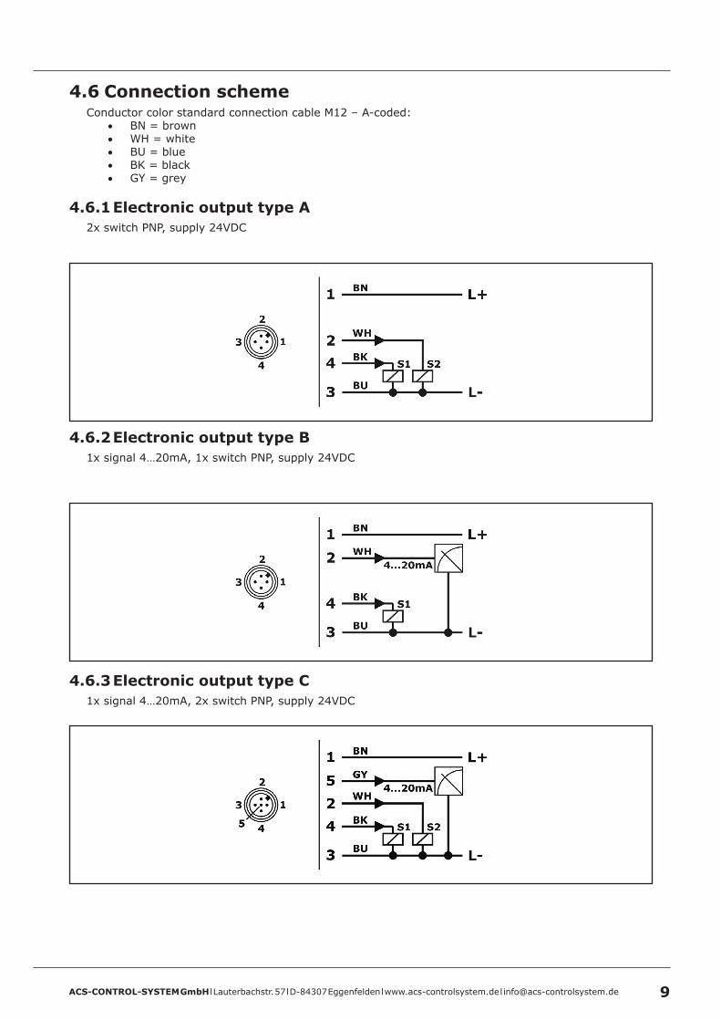
4 .6 Connection schemeConductor color standard connection cable M12 – A-coded:
• BN = brown• WH = white• BU = blue• BK = black• GY = grey
4 .6 .1 Electronic output type A2x switch PNP, supply 24VDC
4 .6 .2 Electronic output type B1x signal 4…20mA, 1x switch PNP, supply 24VDC
4 .6 .3 Electronic output type C1x signal 4…20mA, 2x switch PNP, supply 24VDC

ACS-CONTROL-SYSTEM GmbH l Lauterbachstr. 57 l D-84307 Eggenfelden l www.acs-controlsystem.de l [email protected]
4 .6 .4 Electronic output type D1x signal 4…20mA, 1x switch PNP, supply 24VDC / Desina conformal
ACS-CONTROL-SYSTEM GmbH l Lauterbachstr. 57 l D-84307 Eggenfelden l www.acs-controlsystem.de l [email protected] 11
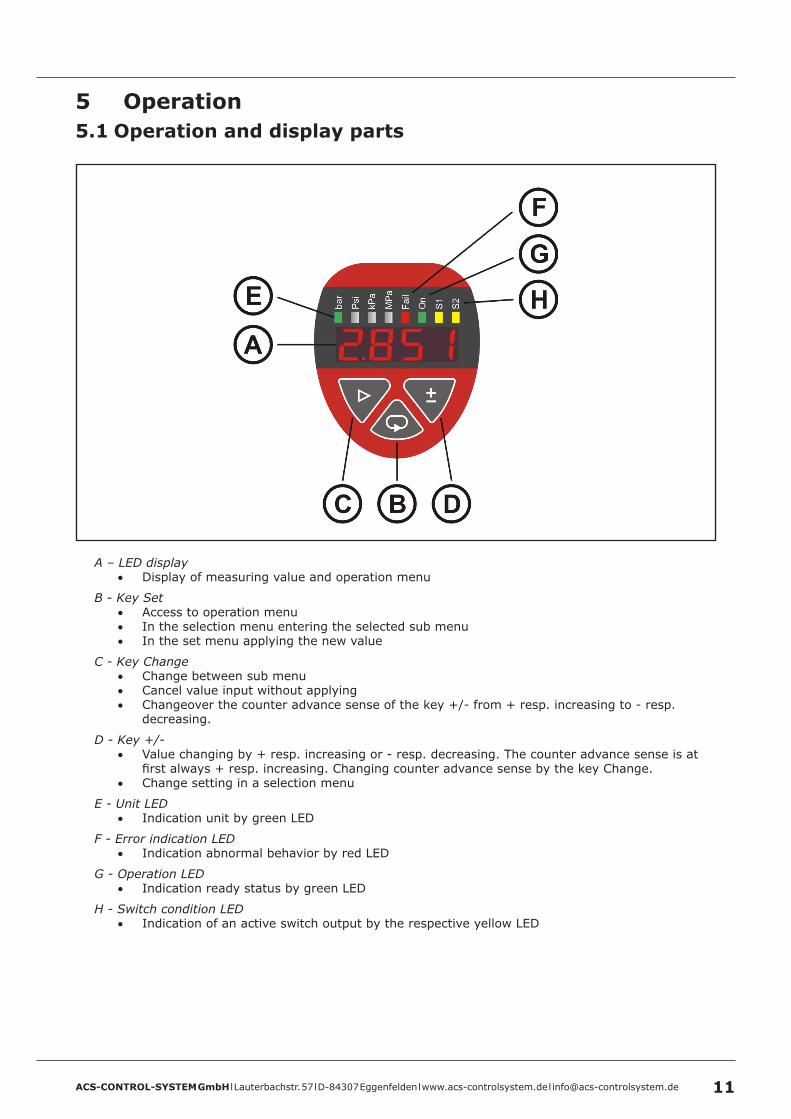
5 Operation5 .1 Operation and display parts
A – LED display• Display of measuring value and operation menu
B - Key Set• Access to operation menu• In the selection menu entering the selected sub menu• In the set menu applying the new value
C - Key Change• Change between sub menu• Cancel value input without applying• Changeover the counter advance sense of the key +/- from + resp. increasing to - resp.
decreasing.
D - Key +/-• Value changing by + resp. increasing or - resp. decreasing. The counter advance sense is at
first always + resp. increasing. Changing counter advance sense by the key Change.• Change setting in a selection menu
E - Unit LED• Indication unit by green LED
F - Error indication LED• Indication abnormal behavior by red LED
G - Operation LED• Indication ready status by green LED
H - Switch condition LED• Indication of an active switch output by the respective yellow LED

ACS-CONTROL-SYSTEM GmbH l Lauterbachstr. 57 l D-84307 Eggenfelden l www.acs-controlsystem.de l [email protected]
5 .2 Function modes5 .2 .1 Run mode
The device records the applied physical measurand and proceeds the chosen functions according to the set parameter.
The active operation is confirmed by the green operation light-emitting diode.
The measuring value is displayed in the display window.
The chosen unit is marked through the come on of the respective green unit light-emitting diode.
The current output and the switch outputs and are driven.
A turned on switch output is signaled by the come on of the respective yellow switch condition LED.
The exceedance of the frame specifications, abnormal behavior conditions and also device malfunctions are displayed static or flashing by the red error indication LED.
5 .2 .2 Programming modeAccess to the function menus by the key Set.
• In the switch function menu – password 1903 – all the adjustable parameter and functions are chosen especially for the use of the device as switch.
• In the transmitter function menu – password 3009 – all the adjustable parameter and functions are chosen especially for the use of the device as transmitter by using the analogue output.
• In the switch point menu – password 1111 – only switch resp. switch back point of the PNP switch output resp. outputs are accessible for fast adjustment. The function of the switch outputs can be displayed.
The display settings, the service parameters system damping, error memory and minimum / maximum value memory and also the reset of all parameter to factory values can be equally accessed from the two menu structures switch function menu and transmitter function menu.
5 .3 Switch output S1 / S25 .3 .1 Switch Point / Reset Switch Point
The input values refer to the current measuring value or acc. to display scaling.The reset switch point must be lower or equal to the switch point.For both switch functions, there is no default minimum difference (hysteresis) between switch resp. switch back point resp. between upper and lower switch point.If the switch back point is set higher or equal to the switch point resp. the lower switch point is set higher or equal to the upper switch point the switch back point is set automatically to the switch point resp. the lower switch point is set automatically to the upper switch point.The red error indication LED is flashing.In the error memory service (SEr) / error memory (ErrM) there will be the indication of the concerning switch output (S1oG or S2oG).
5 .3 .2 Switch Delay Time / Reset Switch Delay TimeThe activation resp. deactivation of the switch output can be biased with a delay time (resolution 0,1s), to realize simple sequence control system.
5 .3 .3 Operating ModeThe operating mode defines the function direction of the switch output.
Normal Open / NO• At the output there is no signal, if the switch condition is not fulfilled.• At the output there is a signal, if the switch condition is fulfilled.
Normal Close / NC• At the output there is a signal, if the switch condition is not fulfilled.• At the output there is no signal, if the switch condition is fulfilled.

ACS-CONTROL-SYSTEM GmbH l Lauterbachstr. 57 l D-84307 Eggenfelden l www.acs-controlsystem.de l [email protected] 13
5 .3 .4 Hysteresis function
The hysteresis function realizes a stable switch state, independent from system conditioned signal fluctuations around the adjusted set point.It can be used for realizing a signal controlled two-position control.The switch range is determined by input the switch point and switch back point. The switch output is activated, if the current measuring value exceeds the switch point and if the set switch point delay time has been expired.The switch output is deactivated, if the current measuring value exceeds the reset switch point and if the set reset switch point delay time has been expired.The actual applied measuring signal can be applied or an arbitrary value can be set as switch resp. switch back point.
5 .3 .5 Window function
The window function realizes a signal range – acceptance region –, where the switch output is set to a definitive switch state.The switch range is determined by input the switch point and switch back point. The switch output is activated, if the current measuring value is inside the area that is defined by the switch point and the reset switch point and if the set switch point delay time has been expired.The switch output is deactivated, if the current measuring value is outside the area that is defined by the switch point and the reset switch point and if the set reset switch point delay time has been expired.The actual applied measuring signal can be applied or an arbitrary value can be set as switch resp. switch back point.
5 .3 .6 Error Indication FunctionThe switch output S1 can be alternatively used for error indication function. Doing this a switch action happens, if the output signal becomes higher than 20mA resp. lower than 4mA.

ACS-CONTROL-SYSTEM GmbH l Lauterbachstr. 57 l D-84307 Eggenfelden l www.acs-controlsystem.de l [email protected]
5 .4 Current outputThe nominal values of the current output (4mA/20 mA) refers to the set signal zero and signal end value.
5 .4 .1 Error SignalDefines, the current output regarding operating range and if errors are registered.
A - Off >> 3.9-21mAB - 3.8mAC - 22mA
5 .4 .2 Invert SignalInverts the current output.
• 4-20mA >> 20-4mA

ACS-CONTROL-SYSTEM GmbH l Lauterbachstr. 57 l D-84307 Eggenfelden l www.acs-controlsystem.de l [email protected] 15
5 .5 Menu structure5 .5 .1 Menu structure switch function - password 1903
ACS-CONTROL-SYSTEM GmbH l Lauterbachstr. 57 l D-84307 Eggenfelden l www.acs-controlsystem.de l [email protected]
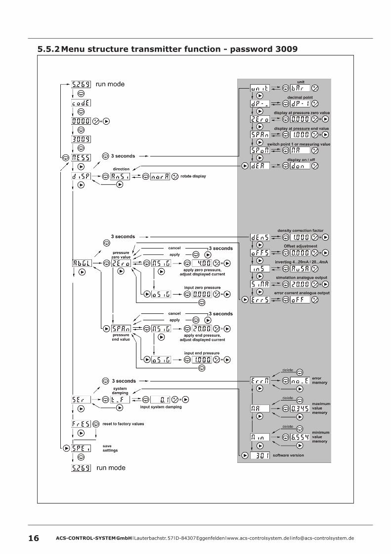
5 .5 .2 Menu structure transmitter function - password 3009
ACS-CONTROL-SYSTEM GmbH l Lauterbachstr. 57 l D-84307 Eggenfelden l www.acs-controlsystem.de l [email protected] 17
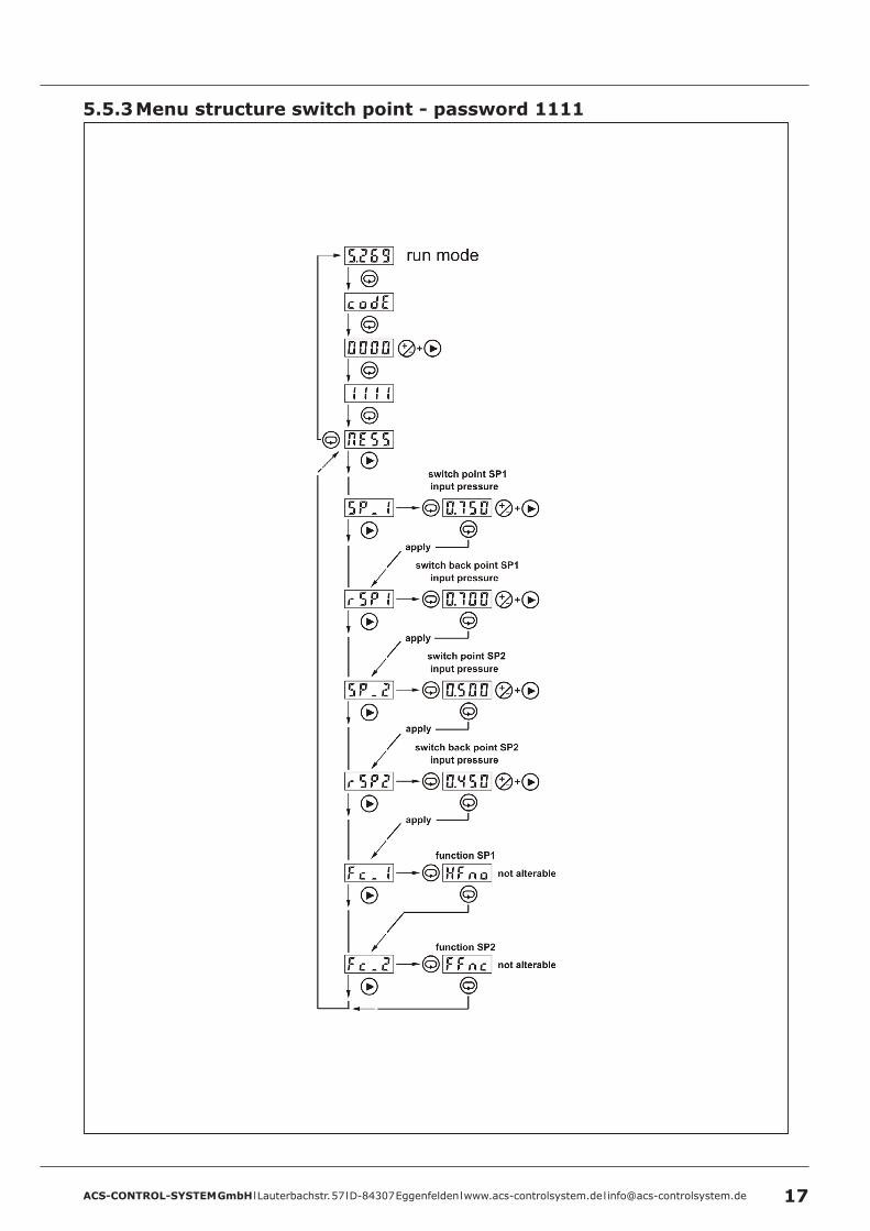
5 .5 .3 Menu structure switch point - password 1111

ACS-CONTROL-SYSTEM GmbH l Lauterbachstr. 57 l D-84307 Eggenfelden l www.acs-controlsystem.de l [email protected]
5 .6 Parameter overviewMenu group Function Input Description
codE 3009 Password input for the access to the transmitter function menu
1903 Password input for the access to the switch function menu
1111 Password input for the access to the switch point menu
Menu group Function Input Description
diSP DISPLAY – includes all parameters concerning the display
AnSi norA View normal
GEdA View rotated by 180°
Unit bAr Unit bar
HPA Unit kPa perhaps not possible when pressure range is too high
PSI Unit psi perhaps not possible when pressure range is too high
NPA Unit MPa perhaps not possible when pressure range is too low
If the gradient of the characteristic >> pressure – display << is changed in the menu group Adjustment, the indication of the unit is deactivated because this value is wrong now.An offset correction, which means an even shift of the lower and the upper pressure reference value does not change the gradient of the characteristic.When changing this settings the switch resp. switch back point are adjusted corresponding to the changed characteristic >> pressure – display <<.
dP-_ dp-0 No decimal point, the measuring value is displayed without decimal place
dp-1 One decimal point, the measuring value is displayed with one decimal place
dp-2 Two decimal point, the measuring value is displayed with two decimal place
dp-3 Three decimal point, the measuring value is displayed with three decimal place
If an increasement of the display resolution is not possible, there will be a scaling correct to the unit. At a conversion e.g. at unit kPa with one decimal point to three decimal points, there will be proceeded automatically a conversion of the unit to bar.Otherwise there is only a shift of the decimal point.When changing this settings the switch resp. switch back point are adjusted corresponding to the changed characteristic >> pressure – display <<.
2Ero Freely adjustable lower display value. This value equals the adjusted lower pressure reference value.When changing this value the switch resp. switch back point are adjusted corresponding to the changed characteristic >> pressure – display <<.
SPAn Freely adjustable upper display value. This value equals the adjusted upper pressure reference value.When changing this value the switch resp. switch back point are adjusted corresponding to the changed characteristic >> pressure – display <<.
SPoN NA Display measuring value - the actual measuring value is shown in the display
SPA Display switch value - the upper limit value of the switch point 1 is shown in the display
dEA don Display indication on – measurement value and status LED are indicated
doFF Display indication off – measurement value and unit LED are deactivated in the run mode.The operation, error and switch condition indicator LED are still in process.When accessing the password input by simultaneous pushing the two operation keys +/- and > for three seconds, the complete display is switched on again.

ACS-CONTROL-SYSTEM GmbH l Lauterbachstr. 57 l D-84307 Eggenfelden l www.acs-controlsystem.de l [email protected] 19
Menu group Function Input Description
SP1 Switch output 1 – includes all parameters concerning the switch output 1
SP_1 NSiG Adjustment with applied signal – The actual applied pressure value is captured as switch point resp. upper switch point
oSiG Adjustment without applied signal – The actual switch point / upper switch point is shown in the display and can now be adjusted by the operation keys +/- and >.
rSP1 NSiG Adjustment with applied signal – The actual applied pressure value is captured as switch back point resp. lower switch point
oSig Adjustment without applied signal – The actual switch back point / lower switch point is shown in the display and can now be adjusted by the operation keys +/- and >.
Fc_1 HF_1 The switch output 1 operates in hysteresis function with switch point and switch back point
FF_1 The switch output 1 operates in window function with lower and upper switch point
Func norF Normal function – The switch output 1 operates in hysteresis or in window function
ErrF Error indication function – The switch output 1 operates in error indication function for the current output. At underrun of 4mA resp. at exceedance of 20mA, the switch output 1 is activated depending on the settings as closed-circuit or as open-circuit.
nonc no The switch output 1 operates in open-circuit principle resp. – no normally open
nc The switch output 1 operates in closed-circuit principle resp. – nc normally closed
dSP1 Switch delay time for switch point / upper switch point of switching output 1.The switching output 1 is only activated, if after the entrance of the switch condition and after the set switch delay time the pressure signal already fulfills the switch conditions. By this e.g. short pressure bursts can be eliminated.The adjustment range is 0...99 seconds, in steps of 0,1 seconds
drP1 Switch delay time for switch back point / lower switch point of switching output 1.The switch output 1 is only activated, if after the entrance of the switch back condition and after the set switch delay time the pressure signal already fulfills the switch back conditions. By this e.g. short pressure bursts can be eliminated.The adjustment range is 0...99 seconds, in steps of 0,1 seconds
SiN1 AuS1 Simulation – the switch output 1 is deactivated
Ein1 Simulation – the switch output 1 is activated
Menu group Function Input Description
SP2 Switch output 2 – includes all parameters concerning the switch output 2
SP_2 NSiG Adjustment with applied signal – The actual applied pressure value is captured as switch point resp. upper switch point
oSiG Adjustment without applied signal – The actual switch point / upper switch point is shown in the display and can now be adjusted by the operation keys +/- and >.
rSP2 NSiG Adjustment with applied signal – The actual applied pressure value is captured as switch back point resp. lower switch point
oSig Adjustment without applied signal – The actual switch back point / lower switch point is shown in the display and can now be adjusted by the operation keys +/- and >.
Fc_2 HF_2 The switch output 2 operates in hysteresis function with switch point and switch back point
FF_2 The switch output 2 operates in window function with lower and upper switch point
nonc no The switch output 2 operates in open-circuit principle resp. – no normally open
nc The switch output 2 operates in closed-circuit principle resp. – nc normally closed
dSP2 Switch delay time for switch point / upper switch point of switching output 2.The switch output 2 is only activated, if after the entrance of the switch condition and after the set switch delay time the pressure signal already fulfills the switch conditions. By this e.g. short pressure bursts can be eliminated.The adjustment range is 0...99 seconds, in steps of 0,1 seconds
drP2 Switch delay time for switch back point / lower switch point of switching output 2.The switch output 2 is only activated, if after the entrance of the switch back condition and after the set switch delay time the pressure signal already fulfills the switch back conditions. By this e.g. short pressure bursts can be eliminated.The adjustment range is 0...99 seconds, in steps of 0,1 seconds
SiN2 AuS2 Simulation – the switch output 2 is deactivated
Ein2 Simulation – the switch output 2 is activated

ACS-CONTROL-SYSTEM GmbH l Lauterbachstr. 57 l D-84307 Eggenfelden l www.acs-controlsystem.de l [email protected]
Menu groupFunction Input Description
AbGL Adjustment – includes all parameters concerning the pressure adjustment
2Ero NSiG Adjustment lower pressure reference value with applied signal- The actual applied pressure value is captured as lower pressure reference value.- The output current of 4mA, that can be adjusted by the control keys +/- and > arbitrarily, is assigned to this pressure reference value. Adjustment range 3,9mA to 21mA.- The 2Ero value of the display refers to this pressure reference value.- If the adjusted measuring range is lower than 25% of the nominal measuring range, the change will be refused and the display shows EEEE.
oSiG Adjustment lower pressure reference value without applied signal- The freely adjustable pressure value, in the set unit - Unit-, is captured as lower pressure reference value.- The 2Ero value of the display refers to this pressure reference value.- The lower output current end value, 4mA, refers to this pressure reference value.- The measuring span cannot be adjusted lower than 25% of the nominal measuring range.
If the end value will not be changed by the same amount as the zero value, the gradient of the characteristic >> pressure – display << is changed and by this the indication of the unit is deactivated because it is no more longer correct.
SpAn NSiG Adjustment upper pressure reference value with applied signal- The actual applied pressure value is captured as upper pressure reference value.- The output current of 20mA, that can be adjusted by the control keys +/- and > arbitrarily, is assigned to this pressure reference value. Adjustment range 3,9mA to 21mA.- The SPAn value of The display refers to this pressure reference value.- If the adjusted measuring range is lower than 25% of the nominal measuring range, the change will be refused and the display shows EEEE.
oSiG Adjustment upper pressure reference value without applied signal- The freely adjustable pressure value, in the set unit - Unit-, is captured as upper pressure reference value.- The SPAn value of The display refers to this pressure reference value.- The upper output current end value, 20mA, refers to this pressure reference value.- The measuring span cannot be adjusted lower than 25% of the nominal measuring range.
If the zero value will not be changed by the same amount as the end value, the gradient of the characteristic >> pressure – display << is changed and by this the indication of the unit is deactivated because it is no more longer correct.
dEnS Freely adjustable density correction factor in the range of 0.500 to 2.000. This factor is applied on the measured pressure concerning to the adjusted pressure range.If a density correction factor divergent to 1 is set, the indication of the unit is deactivated, because the gradient of the characteristic >> pressure – display << has changed and the unit is no more longer correct.
oFFS The measured pressure in the set unit will be shift by the set value accordingly to the sign by maximum ± 5% of the nominal measuring range.Upper and lower pressure reference value will be shift by the same value.To get e.g. a display (desired value) of 0.000 resp. an output current of 4mA at a shown installation dependent pressure of 0.004, the difference between desired pressure value und shown pressure value (0.000 – 0.004) must be input. Thus the value -0.004 must be input.
inS AUSA The output current corresponds to the assignment of the adjustment >> 4...20mA
EinA The output current behaves inverted to the assignment of the adjustment >> 20...4mA
SiNA The current output can be arbitrarily simulated in the whole utilizable range from 3,8mA to 22mA by using the operation keys +/- and >.
ErrS oFF The current output operates linear in the range from 3,9mA to 21,0mA. A current output besides this limits is not possible, the end values are kept at exceedance. An error current output at underrun resp. exceedance does not occur.
FS38 The current output operates linear in the range from 4,0mA to 20,0mA. At underrun of 4mA resp. at exceedance of 20mA a constant current of 3,8mA is generated.
FS22 The current output operates linear in the range from 4,0mA to 20,0mA. At underrun of 4mA resp. at exceedance of 20mA a constant current of 22mA is generated.

ACS-CONTROL-SYSTEM GmbH l Lauterbachstr. 57 l D-84307 Eggenfelden l www.acs-controlsystem.de l [email protected] 21
Menu group Function Input Description
SEr Service – includes all parameters concerning service purposes
t_F Input of the system damping for extraction of short pressure bursts resp. also for reassuring of cyclic fluctuating pressure signals.The adjustment range is 0...40 seconds, in steps of 0,1 seconds
ErrN noE No error recorded in the error memory.
dun Permanent underrun of the maximum permitted system pressure.
dob Permanent transgression of the maximum permitted system pressure.
FLAS An error in the internal nonvolatile data memory (flash) has been detected.
dunt The lower measuring range limit value (display zero) has been underrun.
duEb The upper measuring range limit value (display span) has been exceeded.
Aunt The lower limit value of the current output (3,9mA) has been underrun.
AuEb The upper limit value of the current output (21mA) has been exceeded.
S1oG The switch back point rSP1 of the switch output 1 has been adjusted higher or equal to the switch point SP_1.
S2oG The switch back point rSP2 of the switch output 2 has been adjusted higher or equal to the switch point SP_2.
S1oP The switch output 1 is not activated, although it should be.
S2oP The switch output 2 is not activated, although it should be.
rAN An error in the internal working memory (RAM) has been detected.
NA Maximum value memory – display of the highest measured pressure value.
Nin Minimum value memory – display of the lowest measured pressure value.
301 Version number of the installed firmware
FrES Factory Reset – reset of all parameters to factory values
SPEi Storage – loss protected storage of all parameters
Menu group Function Input DescriptionSwitch point menu
SP_1 The current switch point / upper switch point of switch output 1is shown in the display and can be adjusted by the control keys +/- and >.
rSP1 The current switch back point / lower switch point of switch output 1 is shown in the display and can be adjusted by the control keys +/- and >.
SP_2 The current switch point / upper switch point of switch output 2 is shown in the display and can be adjusted by the control keys +/- and >.
rSP2 The current switch back point / lower switch point of switch output 2 is shown in the display and can be adjusted by the control keys +/- and >.
Fc_1 The set switch function of the switch output 1 is displayed. This setting cannot be changed here.
HFno The switch output 1 operates in hysteresis function with working principle normal open
HFnc The switch output 1 operates in hysteresis function with working principle normal closed
FFno The switch output 1 operates in window function with working principle normal open
FFnc The switch output 1 operates in window function with working principle normal closed
Fc_2 The set switch function of the switch output 2 is displayed. This setting cannot be changed here.
HFno The switch output 2 operates in hysteresis function with working principle normal open
HFnc The switch output 2 operates in hysteresis function with working principle normal closed
FFno The switch output 2 operates in window function with working principle normal open
FFnc The switch output 2 operates in window function with working principle normal closed

ACS-CONTROL-SYSTEM GmbH l Lauterbachstr. 57 l D-84307 Eggenfelden l www.acs-controlsystem.de l [email protected]
5 .7 Error indication at operationThe red error indication light-emitting diode indicates the exceedance of operation limit values, faulty inputs or also device errors.The information, what reason has led to an error indication can be found in each of the two function menus in the area extended functions of the menu point service.Only the last detected error is displayed.The error information in the service menu is not stored in the case of a voltage fail.At every restart of the device the system is completely tested concerning the parameters and settings.
light-emitting diode
error indication in service menu description / remedy
redyellow – flashing no Short circuit at the switch output, whose yellow switch condition LED is flashing.
Check the load at the respective switch output.
red dunPermanent underrun of the minimum permitted system pressure.Check the system pressure in your plant. If the system pressure in within the permitted range, there can be an irreversible device defect.
red dobPermanent exceedance of the maximum permitted system pressure.Check the system pressure in your plant. If the system pressure in within the permitted range, there can be an irreversible device defect.
red FLASAn error in the internal nonvolatile data memory (flash) has been detected.If the error cannot be removed after repeated restart of the device by short voltage interrupts, there can be an irreversible device defect.
red – flashing duntThe lower measuring range limit value (value in Disp-2Ero) has been underrun.Check the system pressure of your plant.This pressure may be lower than the measuring range zero value.
red – flashing duEbThe upper measuring range limit value (value in Disp-SPAn) has been exceeded.Check the system pressure of your plant.This pressure may be higher than the measuring range end value.
red – flashing AuntThe lower limit value of the current output (3,9mA) has been underrun.Check the adjustment of the current output.The system pressure is lower than the pressure concerning to the current output at 3,9mA.
red – flashing AuEbThe upper limit value of the current output (21mA) has been exceeded.Check the adjustment of the current output.The system pressure is higher than the pressure concerning to the current output at 21mA.
red – flashing S1oGThe switch back point rSP1 of the switch output 1 has been adjusted higher or equal to the switch point SP_1.Check the adjustment of the switch output 1
red – flashing S2oGThe switch back point rSP2 of the switch output 2 has been adjusted higher or equal to the switch point SP_2.Check the adjustment of the switch output 2
red – flashing S1oPAn error has been detected at switch output 1.Detach the output load of the switch output 1. If the error cannot be removed after repeated restart of the device by short voltage interrupts, there can be an irreversible device defect.
red – flashing S2oPAn error has been detected at switch output 2.Detach the output load of the switch output 2. If the error cannot be removed after repeated restart of the device by short voltage interrupts, there can be an irreversible device defect.
red – flashing rANAn error in the internal working memory (RAM) has been detected.If the error cannot be removed after repeated restart of the device by short voltage interrupts, there can be an irreversible device defect.
EEEEDisplay while
operation
Wrong password entered – Acknowledgment by control key „Set“Measuring range adjusted to ± 25% of the nominal range – Readjustment necessaryMaximum display value of 9999 has been exceeded – Readjustment necessary
-EEEDisplay while
operation Minimum display value of -999 has been underrun – Readjustment necessary
0.004Display while
operation
At an offset adjustment the unit LED goes outAlways zero and end value must be changed by the same amount. If e.g. only the zero value is changed, the characteristic pressure – display is no more longer correct
ACS-CONTROL-SYSTEM GmbH l Lauterbachstr. 57 l D-84307 Eggenfelden l www.acs-controlsystem.de l [email protected] 23
6 Service6 .1 Maintenance
The device is free of maintenance.
Special substances can lead to solid coatings on the sensor. Seized depositions can lead to faulty measurement results.
In the case of coat forming liquids the sensor must be regularly cleaned e.g. with clear water. Don’t use sharp resp. hard tools or aggressive chemicals for cleaning.
6 .2 DismountingAttention – Risk of burns!Let the device cool down sufficiently fore dismounting itDuring dismounting there is a risk of dangerously hot media escaping.
Attention – Risk of injury!Dismount the device only when the system is pressureless.During dismounting there is a risk of fast escaping media resp. pressure blow.
6 .3 RepairA repair may only be carried out by the manufacturer.
If the device is sent back for repair, the following information’s must be enclosed:• An exact description of the application.• The chemical and physical characteristics of the product.• A short description of the occurred error.
6 .4 ReturnBefore returning the device, the following measures must be performed:
• All adhesive product residues must be removed. This is especially important, if the product is unhealthily, e.g. caustic, toxic, carcinogenic, radioactive etc.
• A returning must be refrained, if it is not possible by 100% to remove the unhealthily product completely, because e.g. it is penetrate into cracks or is diffused through plastic.
6 .5 DisposalDispose of instrument components and packaging materials in an environmentally compatible way and in accordance with the country-specific waste disposal regulations.
This instrument is not subject to the WEEE directive and the respective national laws. Hence, pass the instrument directly on to a specialized recycling company and do not use the municipal collecting points. These may be used only for privately used products according to the WEEE directive.

ACS-CONTROL-SYSTEM GmbH l Lauterbachstr. 57 l D-84307 Eggenfelden l www.acs-controlsystem.de l [email protected]
7 Technical Data7 .1 Auxiliary power supplySupply voltage US 10,5…35VDC, reverse polarity protectedResidual ripple UPP ≤ 2VPP / USmin ≤ US ≤ USmax
Supply current IIn ≤ 60mAAnalogue output max. 22,5mA Switch output with no load
7 .2 Output7 .2 .1 Analogue output – current 4…20mAOperating range IOut
3,9…21mA, min. 3,8mA, max. 22mAPermitted load RL
≤ (US - 10,5V) / 22mAStep response time T90
≤ 3ms (td = 0s)Start-up time tOn
≤ 1s
7 .2 .2 Switch output S1 / S2Function PNP switch to +LOutput voltage UOut UOut ≥ US – 2VOutput current IL 0… ≤ 200mA, current limited, short circuit protectedStep response time T90 ≤ 4ms (td = 0s)Rise time T90 < 30µs (RL < 3kR / IOut > 4,5mA)Start-up time tOn ≤ 1sSwitch cycles ≥ 100.000.000
7 .3 Measuring accuracyReference conditions EN/IEC 60770-1
Environmental temperature 25°CEnvironmental air pressure 860..1060kPaAir humidity 45...75% r.h.Warm-up time tOn 240sSupply voltage US 24VDC ±0,1VCalibration position Vertical
Process connection bottom
Characteristic deviation 3) 5) 6) 12) ≤ ±0,5% FS 2)
Nonlinearity 6) 12) ≤ ±0,3% FS 2)
Hysteresis 6) 12) ≤ ±0,1% FS 2)
Influence of supply voltage ≤ ±0,002% FS 2) / VLong term drift 6) 12) ≤ ±0,2% FS 2) / year - not cumulativeTemperature deviation 6) 12) Tk
4) Zero / Tk 4) Span
Measuring range ≤ 25 bar≤ ±0,02% FS 2) / K (0…80°C)≤ ±0,03% FS 2) / K (-40…0°C / +80…+125°C)Tk
4) Zero / Tk 4) Span
Measuring range ≥ 40 bar≤ ±0,02% FS 2) / K (-40…100°C)≤ ±0,03% FS 2) / K (+100…+125°C)

ACS-CONTROL-SYSTEM GmbH l Lauterbachstr. 57 l D-84307 Eggenfelden l www.acs-controlsystem.de l [email protected] 25
7 .4 Mounting positionMaximum deviation 10) ≤ 4 mbar
Process connection type 5 – Thread G1“, front-flush≤ 10 mbar
2) Referring to nominal measuring span resp. full scale (FS)3) Nonlinearity + Hysteresis + Reproducibility4) Tk = Temperature coefficient5) Limit value adjustment acc. to EN/IEC 60770-16) Specification for TD 7) = 1 (adjusted measuring range = nominal measuring range). Specification for TD 7) ≥ 1 (adjusted measuring range ≤ nominal measuring range) = specification at nominal measuring range x TD 7)
7) Turn-Down TD = nominal measuring range (FS 2)) / adjusted measuring range)10) Device rotated by 180°, process connection upside12) Higher values for special measuring range
7 .5 Process conditionsProcess temperature
The permitted range results from the narrowest limitation of standard range resp. extended range.
-40°C...+100°CExpansionTemperature decoupler -40°C...+125°CLimitationGasket - NBR -25°C...+120°CGasket - FPM -25°C...+200°CGasket - EPDM -40°C...+140°C
Process pressure
[R] Gauge pressure[A] Absolute pressure
Pressure range Over/Burst pressure Vacuum-1…0 bar [R] 5 bar / 6 bar 0 bar [A]
-1…+1 bar [R] 10 bar / 12 bar 0 bar [A]0…0,4 bar [R/A] 2 bar / 2,4 bar 0 bar [A]0…1 bar [R/A] 5 bar / 6 bar 0 bar [A]0…4 bar [R/A] 17 bar / 20,5 bar 0 bar [A]0…6 bar [R/A] 35 bar / 42 bar 0 bar [A]0…10 bar [R/A] 35 bar / 42 bar 0 bar [A]0…16 bar [R/A] 35 bar / 42 bar 0 bar [A]0…25 bar [R/A] 80 bar / 96 bar 0 bar [A]0…40 bar [R] 80 bar / 400 bar 0 bar [A]0…60 bar [R] 80 bar / 400 bar 0 bar [A]0…100 bar [R] 200 bar / 800 bar 0 bar [A]0…160 bar [R] 320 bar / 1000 bar 0 bar [A]0…250 bar [R] 500 bar / 1200 bar 0 bar [A]0…320 bar [R] 800 bar / 1700 bar 0 bar [A]0…400 bar [R] 800 bar / 1700 bar 0 bar [A]0…600 bar [R] 1200 bar / 2400 bar 0 bar [A]0…1000 bar [R] 1500 bar / 3000 bar 0 bar [A]
Measuring range 0…400 bar / 0…600 bar andProcess connection type 0 / type 5 – front-flushValue in the table is only valid at sealing with ring gasket below the hexagon, otherwise max. 1500 bar.
7 .6 Environmental conditionsEnvironmental temperature -40°C...+85°CProtection IP65/IP67 (EN/IEC 60529)Climatic classification 4K4H (EN/IEC 60721-3-4)Shock classification 50g [11ms] (EN/IEC 60068-2-27)Vibration classification 20g [10…2000 Hz] (EN/IEC 60068-2-6)EM compatibility Operation device class B / Industrial range (EN/IEC 61326)Tightening torque ≤ 50NmWeight 0,35kg

ACS-CONTROL-SYSTEM GmbH l Lauterbachstr. 57 l D-84307 Eggenfelden l www.acs-controlsystem.de l [email protected]
7 .7 Materials - process wettedDiaphragm Process connection type 0 / type 5 – front-flush
Process connection type 1 / type 6 – EN 837 / ≤ 25 barSteel 1.4571/316TiProcess connection type 1 / type 6 – EN 837 / ≥ 40 barSteel 1.4542/630Steel 1.4534/SI13800
Process connection Steel 1.4571/316TiGaskets NBR – nitrile-butadiene-rubber
FPM – fluorelastomere (e.g. Viton®)EPDM – ethylene-propylene-dienmonomere
7 .8 Materials - not process wettedTerminal enclosure CrNi-steelControl panel surface PESElectrical connection part Device plug PURPressure compensation element Acrylic copolymerGaskets FPM – fluorelastomere (e.g. Viton®)Fill fluid Process connection type 0 / type 5 – front-flush
Process connection type 1 / type 6 – EN 837 / < 40 barSynthetic oil

ACS-CONTROL-SYSTEM GmbH l Lauterbachstr. 57 l D-84307 Eggenfelden l www.acs-controlsystem.de l [email protected] 27
8 Dimension drawings8 .1 Terminal enclosure
8 .2 Temperature decoupler

ACS-CONTROL-SYSTEM GmbH l Lauterbachstr. 57 l D-84307 Eggenfelden l www.acs-controlsystem.de l [email protected]
8 .3 Process connection8 .3 .1 Internal process membrane
Type 6 – Thread ISO 228-1 – G¼”B, EN 837
Type 1 – Thread ISO 228-1 – G½“B, EN 837

ACS-CONTROL-SYSTEM GmbH l Lauterbachstr. 57 l D-84307 Eggenfelden l www.acs-controlsystem.de l [email protected] 29
8 .3 .2 Front-flush process membraneType 0 – Thread ISO 228-1 – G½”B, front-flush
Type 5 – Thread ISO 228-1 – G1”B, front-flush

C 4PS4S
ACS-CONTROL-SYSTEM GmbH l Lauterbachstr. 57 l D-84307 Eggenfelden l www.acs-controlsystem.de l [email protected] 30
VM S SSPrecont®
Installation material and connection cable are not enclosed in contents of delivery .
TypePS4S Standard
Measuring system – material diaphragm (process wetted) / sensor type M CrNi-steel / strain gauge
Approval S Standard
Process connection 6 Thread ISO 228-1 – G¼”B, EN 837 manometer (without process gasket) 1 Thread ISO 228-1 – G½”B, EN 837 manometer (≥ 40 bar without process gasket) 0 Thread ISO 228-1 – G½”B, front-flush, O-ring gasket not for measuring ranges 0…400 mbar / 0…1 bar / –1…0 bar / 0…1000 bar 5 Thread ISO 228-1 – G1”B, front-flush, O-ring gasket for measuring ranges 0…400 mbar / 0…1 bar / –1…0 bar Y others
Material process gaskets (process wetted) 0 without / NBR – nitrile-butadiene-rubber 1 FPM – fluorelastomere (e.g. Viton®) 3 EPDM – ethylene-propylene-dienmonomere, FDA-listed Y others
Material process connection (process wetted) V CrNi-steel
Material terminal enclosure C CrNi-steel
Measuring range 03 0…400 mbar 05 0…1 bar 08 0…4 bar 09 0…6 bar 10 0…10 bar 11 0…16 bar 12 0…25 bar 13 0…40 bar 14 0…60 bar 19 0…100 bar 20 0…160 bar 21 0…250 bar 22 0…320 bar 23 0…400 bar 24 0…600 bar 25 0…1000 bar, only for process connection type 1, 6 – G½”B, G¼”B (EN 837) 16 –1…0 bar 17 –1…+1 bar YY Special measuring range Electronic – output A 2x switch PNP, supply 24VDC B 1x switch PNP, 1x signal 4…20mA , supply 24VDC C 2x switch PNP, 1x signal 4…20mA, supply 24VDC D 1x switch PNP, 1x signal 4…20mA, supply 24VDC, Desina Electronic – function S Standard
Process temperature 0 Standard –40°C…+100°C 1 Extended –40°C…+125°C, temperature decoupler
Pressure type R Gauge pressure A Absolute pressure (≤ 25 bar)
Measuring system – accuracy 4 0,5%
Electrical connection S Plug M12x1
9 Ordering information9 .1 Order code

ACS-CONTROL-SYSTEM GmbH l Lauterbachstr. 57 l D-84307 Eggenfelden l www.acs-controlsystem.de l [email protected] 31
9 .2 Additional optionsFor the device additional options are available.The respective abbreviation subsequently follows the order code.
• SF LABS-free, silicone-free / paint compatible version• ML Measurement point designation / TAG – Laser marking• KL Customer label on device – Laser marking• TN Type label neutral• WT Factory certification – drink water suitability• WL Factory certification – food suitability• KF Configuration / Preset• WK Factory calibration – calibration certificate
9 .3 AccessoriesAccessories are not content of delivery of the device and must be ordered separately.
9 .3 .1 Installation materialA wide range of accessories for device installation is constantly available, e.g.• Welding sockets• Welding flanges• Blind flanges• Flanges with thread• Reductions• Tube nuts• Siphons• Marking plate measuring point, laser marked• etc.
9 .3 .2 Connection cable / Cable boxConnection cable M12x1, material PUR, shielded• LKZ04##PUR-AS 4-pole, straight, ## = length 2…30m• LKW04##PUR-AS 4-pole, angled, ## = length 2…30m• LKZ05##PUR-AS 5-pole, straight, ## = length 2…30m• LKW05##PUR-AS 5-pole, angled, ## = length 2…30m
Other connection cables, e.g. other material, unshielded or integrated LED are available.
Cable box M12x1• BKZ0412-VA 4-pole• BKZ0512-VA 5-pole
