prediction of helical gear life using wear debris...
TRANSCRIPT

PREDICTION OF HELICAL GEAR LIFE USING WEAR DEBRIS ANALYSIS
MOHD FIRDAUS BIN JAMALUDIN
UNIVERSITI TEKNIKAL MALAYSIA MELAKA

PREDICTION OF HELICAL GEAR LIFE USING WEAR DEBRIS ANALYSIS
MOHD FIRDAUS BIN JAMALUDIN
This report is submitted in
Fulfillment of the requirements for the degree of
Bachelor Degree of Mechanical Engineering (Thermal Fluid )
Fakulti Kejuruteraan Mekanikal
Universiti Teknikal Malaysia Melaka
MAY 2013

ii
DECLARATION
“I acknowledge the work is my own work except for quotations and a summary and
the accompanying expression which have been duly recognized”
Signature :….…………………...............
Author : MOHD FIRDAUS BIN JAMALUDIN
Date : 31 MAY 2012

iii
ACKNOWLEDGEMENT
In the name of Allah S.W.T, the most gracious and the most merciful, thanks
a lot for giving me this strength and opportunity to complete this report. I take this
opportunity to express my gratitude to the people who have been instrumental in the
successful completion of this project.. I would like to express my appreciation to my
Faculty of Mechanical Engineering (FKM) in allowing me to precede final year
project. Furthermore, heartiest gratitude to my supervisor, En. Reduan bin Mat Dan
for his supervision and assistance during my period of research and study. A million
thank for his willingness to evaluate my research papers and revising my report prior
to submission. His kindness, concern, guidance, constructive critics, support,
encouragement and invaluable advice are so precious for me. Besides that,
unforgettable for my beloved family, friends and supportive people, thanks a lot for
everything. Last but not least, I would like to thank to everyone especially my
course mate who have been so supportive and motivation during the project. The
guidance and support received from you, who contributed and are contributing to this
project, was vital for the success. I am grateful for their constant support and help.

iv
ABSTRAK
Hampir semua mesin yang digunakan di industri melibatkan komponen
mekanikal. Antara komponen mekanikal yang akan terlibat dalam kajian ini ialah
gear.Masalah pada gear boleh menyebabkan kos penyelenggaraan dan operasi
meningkat.Jadi dalam kajian ini, pelajar akan mengkaji bagaimana hendak meramal
kegagalan set gear helix dengan menggunakan kaedah wear debris analisis.Kaedah
untuk menganalis kegagalan gear yang akan digunakan ialah kaedah matematik
modeling dan meggunakan kaedah experiment. Kaedah matematik modeling yang
digunakan ialah standad BS ISO 6336-2 yang akan digunakan untuk meramal jangka
hayat sesuatu gear bagi menganalisis secara teori. Dengan menggunakan maklumat
daripada pembuat gear, janka hayat sesuatu gear helix akan di tentukan. Selain itu,
kajian ini juga mengkaji bagaimana mekanisma dan fenomena haus terhadap gear
helix semasa beroperasi melalui gear test rig experiment. Melalui kaedah ini,
pandangan terhadap kehausan gear adalah lebih jelas. Projek ini menerangkan
tentang objektif dan skop projek secara terperinci bagi memberi pandangan yang
jelas terhadap kaedah yang digunakan serta mekanisma oleh set gear sebelum
dibuktikan kegagalanya pada hadnya.

v
ABSTRACT
Almost all machines used in industry involve mechanical components.
Among the mechanical components that are involved in this study was gear. Problem
in gear can increase the cost of maintenance and operation increased .So, this study
try to predict the failure helical gear sets using wear debris analysis .Methods to
predict failure of gear to be used are mathematical modeling and experiment
methods. Mathematical modeling method used is based on BS ISO 6336-2 standards
used to predict the lifespan of a gear to analyze theoretically. By using information
from manufacturer, life of a helical gear will be determined.BS ISO 6336-2
calculation is based on the contact stress at the pitch point of the meshing gears, or at
the inner point of single pair tooth contact. BS ISO 6336-2 also states the contact
stress shall be less than it permissible stressed for preventing failure. In addition, this
study also examines how the mechanism and wear on the helical phenomenon while
operating through gear test rig experiment. The physical inspection is use to assertion
the deterioration of helical gear during experiment. Through the calculation, the
result to start pitting is after 46 hours after run the machine for 30kg applied load. In
experiment, the gear start to have micro pitting defect after 12 hours run the gear test
rig. The number of pitting defect was increase proportionally with time during
experiment. The experiment result use to validate the result of the calculation using
BS ISO 6336-2.

vi
TABLE OF CONTENT
CHAPTER CONTENT PAGE
DECLARATION i
ACKNOWLEDGEMENT iii
ABSTRAK iv
ABSTRACT v
TABLE OF CONTENT vi
LIST OF TABLE viii
LIST OF FIGURE x
LIST OF SYMBOL xii
LIST OF EQUATION xiii
CHAPTER I INTRODUCTION
1.1Research Background 1
1.2 Research Overview 2
1.3 Problem Statement 3
1.4 List of Objective 3
1.5 Scope of Project 3
CHAPTER II LITERATURE REVIEW
2.1 Introduction 4
2.2 Typical Defect in gear 5
2.3 Types of Gear Damage 6
2.3.1 Pitting and Micro pitting 7

vii
2.3.2 Scoring 9
2.3.2.1 Initial Scoring 10
2.3.2.2 Moderate scoring 10
2.3.2.3 Destructive Scoring 10
2.3.3 Scuffing 12
2.3.4 Wear 15
2.4 Wear Mechanism 16
2.5 Stage of Wear 17
2.6 Wear Classification due to Mechanism 18
2.7 Type of Wear 19
2.8 Wear Due to Mechanical Process 20
2.8.1 Abrasive Wear 20
2.8.1.1 Cutting Abrasive wears 22
2.8.1.2 Fracture abrasive wear 22
2.8.2.3 Fatigue abrasive wear 22
2.8.2.4 Grain Pull Out abrasive wears 22
2.8.2 Adhesive Wear 23
2.8.3 Fatigue Wear 24
2.8.4 Erosion Wear 26
2.8.5 Cavitation Wear 27
2.8.6 Fretting Wear 29
2.9 Wear Debris Analysis 30
CHAPTER III METHODOLOGY 31
3.1Introduction 31
3.2 Flow Chart 32
3.3 Theoretical life calculation for gear 33
3.4 Experimental using gear test rig 36
3.4.1 Gear Test Rig Preparation 36
3.4.2 Gear Test Rig Specification 38
3.4.3 Gear Specification 39
3.5 Wear Debris Analysis 40

viii
3.5.1 Procedure of experiment 41
3.6 Gear Test Rig Operation Procedure 42
3.7 Sampling Procedure 46
3.8 Visual Inspection Procedure 47
3.9 Wear Debris Classification 48
CHAPTER IV RESULTS AND DISCUSSION
4.1 Introduction 48
4.2Result 50
4.2.1 Physical inspection 51
4.2.2 Debris Image result 57
4.2.3 Temperature measurement result 62
4.3 Theoretical result 63
4.3.1 Sample Calculation (BS ISO 6336-2) 63
4.3.2 Stress and Force Analysis 74
4.3 Discussion 81
4.3.1 Discussion on experimental results 81
4.3.2 Discussion on the theoretical results. 83
CHAPTER V CONCLUSION
5.0 Conclusion 85

ix
LIST OF TABLE
BIL TITLE PAGE
2.1 Pitting Damage 8
2.2 Type of Scoring Damage 11
2.3 Type of Scuffing Damage 14
3.1 Gear specification 38
4.1 Gear Surface from Visual Inspection during Experiment 51
4.2 Debris Image Result Using Microscope 57
4.3 Tabulate Temperature for Oil Gear during Operation 62
4.4 Variable Result from Calculation 69
4.5 AK, vK
, HK and HK
For Helical And Spur Gear 71
4.6 Contact Stress 72
4.7 Considered Factor 72

x
LIST OF FIGURE
BIL TITLE PAGE
2.1 Initial and Destructive Pitting 11
2.2 Abrasive Wear Mechanism 20
2.3 Moderate Adhesive Wear 24
2.4 Fatigue Wear Mechanism 25
2.5 Cavitation Wear 27
2.6 Fretting Wear 29
3.1 Flow Chart 31
3.2 Gear Test Rig Detail Drawing 36
3.3 Gear Test rig (Frame) 37
3.4 Drawing of Gear 38
3.5 Gear Test Rig Machine 41
3.6 Gear test rig 42
3.7 Clutch Load 42
3.8 Drive gear and stopper 43
3.9 Load lever and weight 43
3.10 Tachometer 55
3.11 Oil sampling apparatus 56
4.1 Graph of temperature, (°c) vs. Time (hour) 62
4.2 Gear Test rig 74
4.3 Gear test rig schematic diagram 74
4.4 Free Body Diagram for gear Test rig system. 74
xi
4.5 Free body Diagram 75
4.6 Reaction force at testing gear 76
4.7 Moment of inertia of circle. 78
xii
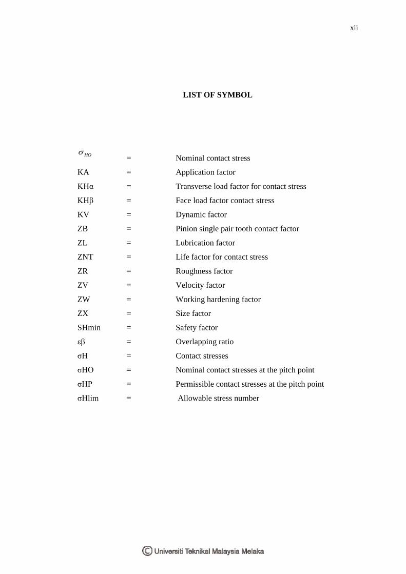
LIST OF SYMBOL
HO = Nominal contact stress
KA = Application factor
KHα = Transverse load factor for contact stress
KHβ = Face load factor contact stress
KV = Dynamic factor
ZB = Pinion single pair tooth contact factor
ZL = Lubrication factor
ZNT = Life factor for contact stress
ZR = Roughness factor
ZV = Velocity factor
ZW = Working hardening factor
ZX = Size factor
SHmin = Safety factor
εβ = Overlapping ratio
σH = Contact stresses
σHO = Nominal contact stresses at the pitch point
σHP = Permissible contact stresses at the pitch point
σHlim = Allowable stress number

xiii
LIST OF EQUATION
NAME OF EQUATION LIST OF EQUATION
Equation 4.1
HHVAHOBH KKKKZ .
Equation 4.2 U
U
bd
FZZZZ t
EHHO
1
1
Equation 4.3 wt
wtH
tZ
sincos
coscos22
b
Equation 4.4 3
4
Z
Equation 4.5 bt
a
p
g
Equation 3.6 ))(cos( ttbt mp
Equation 4.7 cos
nt
mm
Equation 4.8 wtbabaa ddddg sin2
1 2
2
2
2
2
1
2
1
Equation 4.9
1
3
4Z
Equation 4.10 nm
b
sin
Equation 4.11 cosZ
Equation 4.12 lim
lim ))()()()()((
H
XWRVLNTH
HPS
ZZZZZZ

1
CHAPTER I
INTRODUCTION
1.1 Research Background
In recent years, rapid industrialization in the country becomes a phenomenon.
Many factories use machinery or equipment involving mechanical components. Among
these are the gears. Gears are used to transmit energy, power and torque to be converted
into mechanical energy. Some of the gear in use is the helical gear. Helical gear use as
mechanical component or rotating machine part that used to transmit power, energy,
force and torque that convert into mechanical energy. However, until at the certain time
or period the helical gear life reaches the limit. So it will be a challenge in maintenance
engineering to make sure the life of gear is suitable to operate before the gear failure.
Hence, this project helps the maintenance sector to predict gear life using several
methods. Then, the comparison of the result from the method that will be used in this
project.

2
1.2 Research Overview
The project main objective is to predict onset of failure of helical gear life using
wear debris analysis. The research about how to predict helical gear life using identified
method. The method could involve in this research should be theoretical and
experimental method. Then, the comparison about the result of both methods should
give the efficiency view.
By using wear debris that obtains from the test, it used to analyze and then come
out with several data and result to predict the helical gear life. Regarding wear debris
obtain, it could determine the mechanism of wear. In this research also contain a study
about the failure onset helical gear during the test. Then, the finding and understanding
about of the helical gear failure will be cover during the research. Then, the observation
on the behavior of the helical gear wear mechanism is a part of research activities. From
there, several types of wear mechanism should be defined based on the wear debris
obtains. The studies about type of wear mechanism also cover to determine helical gear
life.
In theoretical method, gears wear mathematical modeling that allows
approximate to predict gear life will be useful. Using BS ISO 6336-2 standard
formulation is used to predict helical gear life under pitting condition. The used
formulation estimation is validated by using wear quantitative feature analysis which is
able to provide actual gear wear trends.

3
1.3 Problem Statement
Gear is an important component in a machine or equipment. The rubbing
and rolling action in the gear meshing will normally generate wear debris.
However, the increase in abnormal loading due to misalignment will increase the
risk of unpredicted gear failures. These failures will result in the unexpected lost
of production and increase of maintenance cost. Hence, it is recommended to
predict the onset of failure of the gear to allow replacement at the right time
before catastrophic failure occurs.
1.4 List of Objectives
To study the phenomena and mechanism wear of gear.
To predict the onset of failure of helical gear using Wear Debris Analysis
technique.
1.5 Scopes of Project
Laboratory gear test rig
Study on the helical gear failure.
Wear debris analysis.

4
CHAPTER II
LITERATURE REVIEW
2.0 Literature Review
2.1 Introduction
Nowadays, research and development in the manufacturing process were rapidly
improved day by day. The improvement of research and development in manufacturing
process give to many advantages in manufacturing industry especially. Research and
development in the maintenance sector improved a lot in manufacturing industry.
Maintenance research and development has been looking as important part as the
problem needs to solve in manufacturing or production process. The problem occurs
will cause waste in the industry especially will affect to the core of business itself.
Since then, there is growing involvement in study of wear on a manufacturing
process. Wear is a physical damage on the surface of solid surface that reduce the
mechanical efficiency and a retrievable loss of material in the form of wear debris. Wear
at moving solid body is a normal phenomena in any application The result from that
contact surface between two solid surfaces that moving and experience wear will obtain
particle or wear debris that will be used in analyzing the wear phenomena and
mechanism of gear.

5
2.2 Typical defect in Gear
The majority of problems associated with things as well as moving component
bearings begin because local stage flaws in touch areas in between getting in touch with
physiques. Equipment problems tend to be started within the teeth meshing area as well
as showing problems within the moving get in touch with areas. Defect of gear possible
to identify as well as identify could be categorized within 3 classes regarding their own
cause:
1. Installation defect.
2. Defects develop in operation.
3. Defect on the neighboring element which produce dynamic load on bearings and
gears.
Crack and also spalls will be the many radical problems inside the stand. Spalling is
actually brought on by the higher, nearby, get in touch with tension levels local beneath
the actual get in touch with area. Typically any split will be trigger info substance
introduction positioned through this zoom regarding large tensions. The particular split
moves along as a result of duplicated cyclical packing in the course of equipment
functioning. With a specific period the particular split actually reaches a crucial
dimension as well as the progress grows to be unstable.In the unstable phase the crack
rapidly grows and eventually reaches the surface, and a piece of material comes loose,
creating a spall. All defects in table modify the characteristic vibration signature. One of
the main tasks of machine monitoring is to identify and localize these defects from
measured signatures. There have several typical defects in gear such as:
1. Localized surface damage
2. Wear or inadequate lubrication
3. Tooth root cracks, missing tooth
4. Pitch error
5. Eccentricity

6
2.3 Type of Gear Damage
Gearing is a crucial part of several components in many machines. The particular
extensive application regarding gears in the machine and also mechanism, which
includes high speed and also heavy duty to operate with lower temperatures and also
high temperature and also beneath exposure to any excessive load cause damage and
also catastrophic failure with their tooth result in simply by transmitting load, rotation
speed or perhaps thermal therapy along with manufacture and operating condition .The
result of gear damage majority associated with typical of gear damage. [A. M. Goman
et.al., 2000]
Since there is increasing engagement in examine regarding gear damage inside
manufacturing process, the effect coming from gear damage obtain particle or perhaps
wear debris which will be found in examine the wear phenomena and also the
mechanism of gear. Then, through the process operation the damage of gear were
identified into several types.
The type of damage classification is due to the gears in the machine and
mechanism, including high speed and applying load on the system .The main damage of
gear is state bellow [A. Miltenovic, 2011]
1. Pitting
2. Scoring
3. Scuffing
4. Wear
Study on gear damage give use more advantage to prevent the failure in gearing
system. The research of gear damage gives more information about the process and the
causes of gear damage. Hence, the damage on gear can prevent in term to reduce the
phenomena of gear failure cause by the abnormal load during the operation.

7
2.3.1 Pitting and Micro pitting.
Pitting or macro pitting can be surface damage through cyclic contact to strain
transmit by having a lubrication that may be throughout as well as at the
elastohydrodynamic plan. Pitting is just about the most common reasons behind gear
failure. Then, it also influences antifriction bearings, cams, and also other appliance
factors through which materials experience rolling as well as sliding off the contact
under excessive load. Pitting is definitely the result of repeated contact stresses that
cause gear surface and also subsurface fatigue and detachment with a material fragment
from gear tooth surface types which will surface types undergo rolling or sliding under
excessive load [Hermann Siebert, Michael Hochman, 2012].
Pitting happens when exhaustion crack tends to be initiated about the tooth
surface or simply below the surface. Usually pits are caused by surface crack brought on
by metal to metal get in touch with of asperities or even defect because of low
lubrication layer on the surface that cause the lubricant viscosity was reduced through
the operation. High speed gears along with smooth area and large lubricant layer may
encounter pitting because of subsurface break.
Pits tend to be formed whenever this breakthrough with the tooth surface and
since the particle obtain. Pitting may also cause through contamination associated with
lubricant. These contaminants create surface stress focus points which reduce the
lubrication film thickness to create pitting [K. Gopinath, 2012]. Table below shows the
picture types of pitting damage on gear through the operation. Those types of pitting
damage are:
1. Pitting and micro pitting
2. Pitting through hardened gear
3. Pitting on carburized gear
4. Surface failure of nitride gear

8
Table 2.1: Pitting Damage (Source: Dr. Ing. Klaus Michaelis, 2011)
A huge pressure in surface does not lead to the sudden failure on gear surfaces,
but at the time, small holes (pits) emerge inside shape involving shell in tooth flank. Pit
peak always points inside sliding route. This destruction occurs by having a cyclic
fatigue on account of repeated elastic and plastic deformations in the surface. The holes
occur only from a sufficiently numerous overruling. Only when initial pitting is present,
the situation is just not dangerous but if destructive pitting destroys occurs on the flank
along with cause of failure due to noise along with fatigue.
pitting and micro pitting
Pitting through hardened gear
Pitting on carburized gear
Surface failure on nitride gears

9
Figure 2.1: Initial and Destructive Pitting (Source: A. Miltenovic, 2011).
The Figure 2.2, describes the condition of the gear. From the figure the initial
pitting is not dangerous. Since the initial pitting occurs, it will generate destructive
pitting on the gear surface. Destructive pitting Destructive pitting destroys the flank and
causes failure due to noise and fatigue.
2.3.2 Scoring
Scoring is a result of combination associated with two unique activities: Firstly,
lubrication failure within the contact area and second, establishment associated with
metal to metal surface contact. Later upon, welding as well as tearing action caused by
metal surface contact by removing the actual metal quickly and continuously so far,
speed as well as oil heat remain in the same level. The rating is categorized into
preliminary, moderate as well as destructive [K. Gopinath, 2011].

10
Scoring damage mark is stick to the course of motion on the bearing surface. The
scoring damage marks start the contact surface where the dirt particle connects the
motion layer and form a consistent mark around the end with the gear surface area, the
trailing edge around the right with the pad inside the Photograph, or stop having an
embedded particle. Scoring is among abrasive wear, adhesive wear gives discontinuous
tears as opposed to clear uninterrupted scores.
2.3.2.1 Initial scoring
Initial scoring occurs in the high places left through previous machining.
Lubrication fails at these types of spots results in initial rating or scuffing because shown
within table 2.2. Once these types of high places are eliminated, the stress boils down as
force is distributed on the larger region. The scoring will stop when the load, pace and
heat of essential oil remain the same or decreased. Initial rating is non-progressive and it
has corrective action related to it [K.Gopinath, 2011].
2.3.2.2 Moderate scoring
Moderate scoring occurs if the Scoring progresses at tolerable rate. After initial
scoring if the load, speed or oil temperature increases, the scoring will spread over to a
larger area. It is shown in table:
2.3.2.3 Destructive scoring
After the initial scoring, if the load, speed or even oil heat increases substantially,
then serious scoring sets in with heavy metal torn areas spreading rapidly throughout as
shown within table below. Scoring is usually predominant within the pitch collection
region because elastohydrodynamic lubrication may be the least from that area. In dried
running areas may grab [K.Gopinath, 2011].