prediction of the flow inside a micro gas turbine combustor · prediction of the flow inside a...
TRANSCRIPT
Jurnal Mekanikal June 2008, No. 25, 50 - 63
50
PREDICTION OF THE FLOW INSIDE A MICRO GAS
TURBINE COMBUSTOR
Yehia A. Eldrainy, Johann Jeffrie Muhamad Ridzwan, Mohammad Nazri Mohd Jaafar*
Department of Aeronautical Engineering, Faculty of Mechanical Engineering,
Universiti Teknologi Malaysia, 81310 UTM Skudai, Johor, Malaysia
ABSTRACT
The main purpose of this study is to predict the flow dynamics inside a micro gas turbine combustor model. The flow field inside the combustor is controlled by the liner shape and size, wall side holes shape, size and arrangement (primary, secondary and dilution holes), and primary air swirler configuration. Air swirler adds sufficient swirling to the inlet flow to generate central recirculation region (CRZ) which is necessary for flame stability and fuel air mixing enhancement. Therefore designing an appropriate air swirler is a challenge to produce stable, efficient and low emission combustion with low pressure losses. Four axial flat vane swirlers with 20°, 30°, 45° and 60° vane angle corresponding to swirl number of 0.27, 0.42, 0.74, and 1.285 respectively were used in this analysis to show vane angle effect on the internal flow field. The flow behavior was investigated numerically using CFD solver FLUENT 6.2. This study has provided physical insight into the flow pattern inside the combustion chamber. Results show that the swirling action is augmented with the increase in the vane angle, which leads to increase in the turbulence strength, recirculation zone size, and amount of recirculated mass. However, all these happen at the expense of the increase in pressure losses. In case of 20° swirler (swirl number < 0.4), the produced swirling flow is not enough to generate CRZ. Keywords: Gas turbine combustor, turbulence, combustor aerodynamics, CFD,
numerical simulation 1.0 INTRODUCTION Micro gas turbines are the newest type of gas turbines being used for stationary power generation. They are small gas turbines that develop output power of 25 kW to 500 kW and they have many potential advantages compared to other technologies for small-scale power generation. These advantages include number of moving parts, compact size, light-weight, greater efficiency, lower emissions, lower electricity cost, and opportunity to utilize natural gas, besides other fuels
* Corresponding author: E-mail: [email protected]
Jurnal Mekanikal, June 2008
51
like diesel, landfill gas, ethanol, industrial off-gases and other bio-based liquids and gases [1].
In a micro gas turbine, the combustor operating conditions could be rather different from those of a larger gas turbine. The reduced values of cycle pressure and turbine inlet temperature make the adoption of recuperated cycles mandatory. In consequence the inlet air flow is relatively of low density. Another consequence is the small temperature rise in the combustion chamber, and hence a low value of the fuel to air equivalence ratio [2], [3]. Therefore it is of great importance to develop a combustion system that can offer best performance at these operating conditions of micro gas turbine. For that reason, better understanding of the flow inside the gas turbine combustor can lead to optimum design appropriate for these conditions.
Designing and developing a gas turbine combustor requires expensive testing with many iterations. Previously, the designer, to arrive at final design, relied primarily on the past experience, test results and analyses based on empirical formulations [4]. High ranges of temperatures, pressures and flow rates in the combustor result in a flow field where comprehensive experimental data are so expensive to obtain. Thus, Computational Fluid Dynamics (CFD) is an attractive design tool, since it has the potential to explain the flow physics inside the combustor. A numerical analysis can be used to reduce the number of design iterations by providing an approach to the changes that a design parameter should undergo regarding the characteristics of the flow. This study focuses on flow aerodynamics inside a small gas turbine combustor using CFD. The flow pattern inside the combustor is significantly affected by the air swirler configuration. This paper, therefore, numerically investigates the swirler configuration effects on the flow inside the combustor.
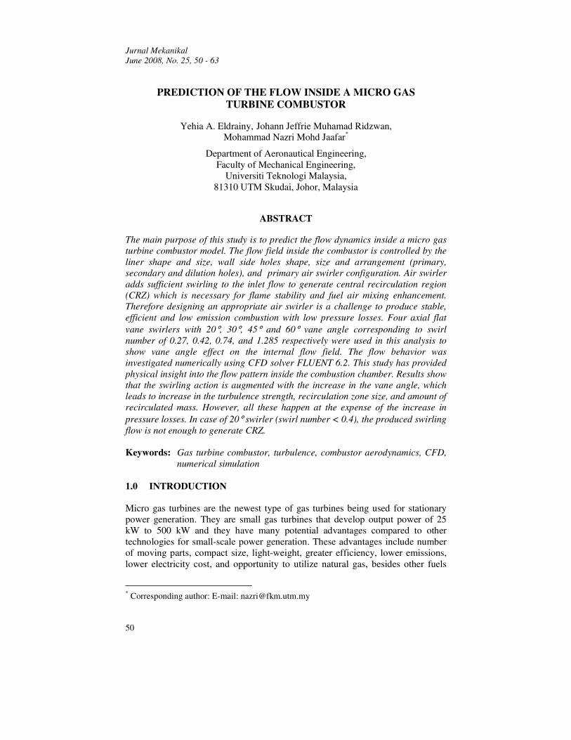
Air swirler introduces air tangentially into the combustion chamber; consequently the air is forced to change its path, which contributes to the formation of swirling flow. The balance in force could be demonstrated by the movement of static pressure in the combustion chamber and can be calculated by measuring the distribution of the tangential velocity. Low pressure in the core centre of the swirling flow is created and as a result, swirl vortex is formed [5]. The recirculation region in free swirl flow is shown in Figure 1.
Figure 1: Recirculation zone in swirling flow [2]
As the level of applied swirl increases, the velocity of the flow along the centreline decreases, until a level of swirl is reached at which the flow becomes
Jurnal Mekanikal, June 2008
52
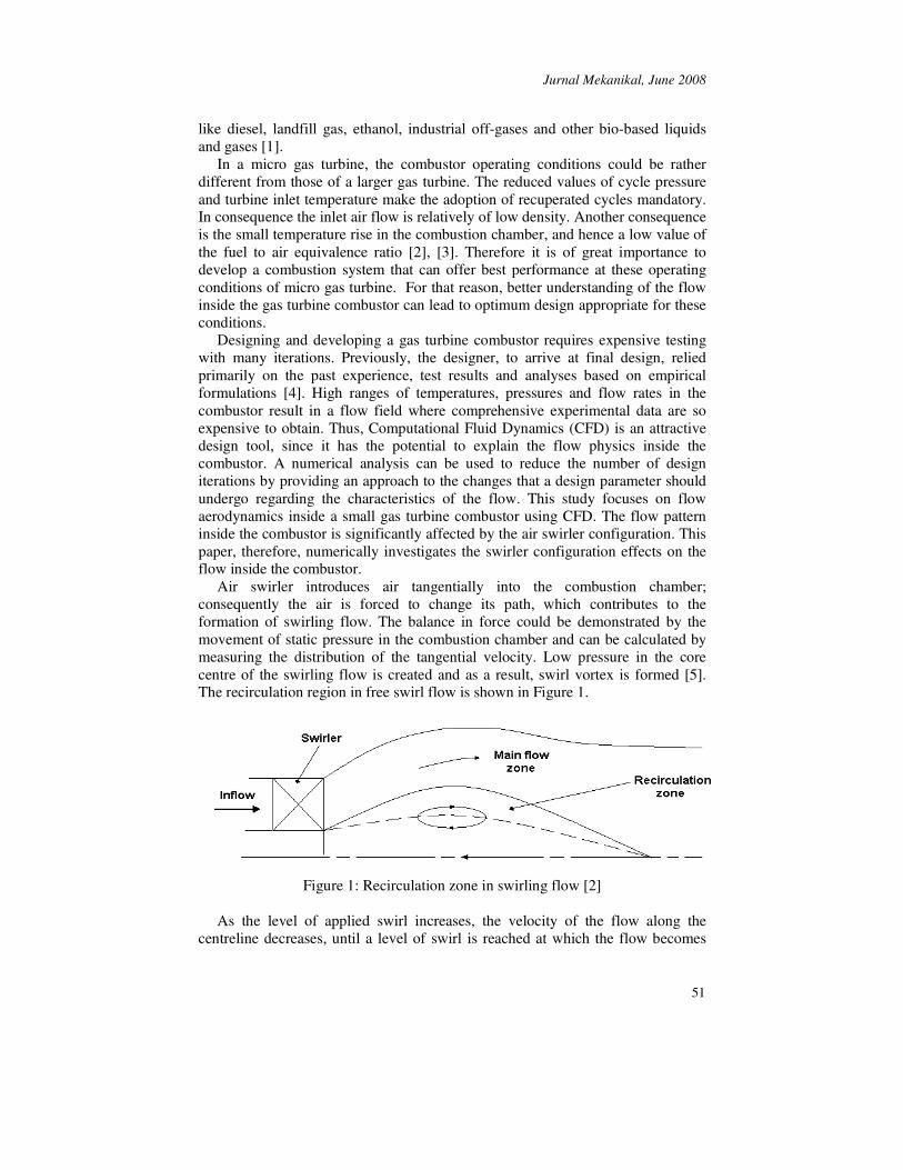
stationary. As the swirl is increased further, a small bubble of internal recirculating zone is formed. This, the vortex breakdown phenomenon, heralds the formation of large-scale recirculation zone that helps in stabilizing the flame. It has been concluded [6], [7] that the large torroidal recirculation zone plays a major role in the flame stabilization process by acting as a store for heat and chemically active species and, since it constitutes a well-mixed region, it serves to transport heat and mass to the fresh combustible mixture of air and fuel.
The level of swirl or swirl strength can be represented in term of swirl number which is defined as the ratio between axial flux of the angular momentum to the axial momentum [4].
��
= R
0
R
0
Nrdr2uuR
rdr2u)wr(S
πρ
πρ (1)
where w, u, ρ and r are the tangential and axial velocity components, density and radius respectively.
For a flat vane axial swirler, the swirl number is related to the swirl angle θ, inner radius ri and outer radius ro as given by [4] and [8]:
θtan)/(1)/(1
32
2
3
��
���
�
−−
=oi
oiN rr
rrS (2)
Previous researchers have studied the effect of varying the blade angle, which
in turn varies the swirl number, on combustion performance. Drake and Hubbard [9] studied the effect of swirl on completeness of combustion and discovered that there was an optimum swirl blade setting. Claypole and Syred [10] investigated the effect of swirl strength on the formation of NOx. Using natural gas (mainly methane), they used swirlers of swirl numbers from 0.63 to 3.04 using natural gas (mainly methane). They concluded that at swirl number of 3.04, much of the NOx in the exhaust gases was recirculated back to the flame front. The total emissions of NOx were reduced, however, at the expense of loss in combustion efficiency.
Mestre [11] compared the effects of swirling and non-swirling systems on combustion characteristics. He clarified that the existence of swirl improves combustion efficiency, decreases pollutant gas-emissions and increases adiabatic flame temperature. In addition he observed that a shorter blue flame was generated with the presence of swirl, indicating a good mixing, while non-swirling combustion resulted in a longer yellow flame as a result of poor mixing.
Chigier [12] concluded in his study that swirling flow could stabilize the combustion process and improve the mixing of fuel and air as well; swirl flow affected the flame length, size, density, and stability.
An important effect of swirl on the flow field is the generation of the recirculation zone or aerodynamic blockage, where adverse pressure gradient occurs in the direction of the flow. This vortex breakdown phenomenon occurs only if the strength of swirl is large enough. For a weak swirl (SN < 0.4), the slope
Jurnal Mekanikal, June 2008
53
of the axial pressure due to swirling motion is not big enough to produce an internal recirculation, whereas for a strong swirl (SN > 0.6), radial and axial pressure slopes are formed downstream of the swirler exit plane creating a recirculation zone (Figure 2) in the axial direction [4].
Figure 2: Axial velocity profile and swirl inside a strong swirl [2]
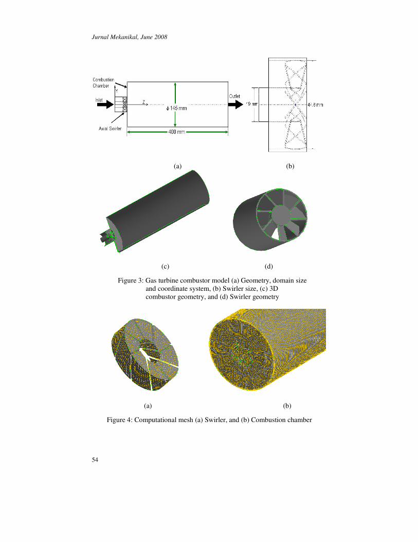
2.0 COMPUTATIONAL FLUID DYNAMICS CFD has grown from a mathematical curiosity to become an essential simulation tool in most fluid dynamics branches (aerospace, propulsion, weather prediction, etc.). CFD has received extensive attention throughout the international community since the advent of the digital computer. The attraction of using CFD is twofold. First, there is the need to model physical fluid phenomena that cannot be easily simulated or measured with a physical experiment, for example highly swirl flow, hypersonic aerospace vehicles and other applications. Second, the use of CFD to investigate physical fluid structure is more cost effective and more rapid than using experimental procedures. 2.1 Mathematical Analysis Figure 3 presents the physical model of the present study and its relevant geometrical dimensions. Four different axial swirlers with vane angles 20°, 30°, 45°, and 60° were investigated in this study to compare their effects on the flow field inside gas turbine combustor. Figure 4 shows the computational domains used in this study. The working fluid is considered to be incompressible with constant thermal properties and the flow is assumed to be steady.
Jurnal Mekanikal, June 2008
54
(a) (b)
(c) (d)
Figure 3: Gas turbine combustor model (a) Geometry, domain size
and coordinate system, (b) Swirler size, (c) 3D combustor geometry, and (d) Swirler geometry
(a) (b)
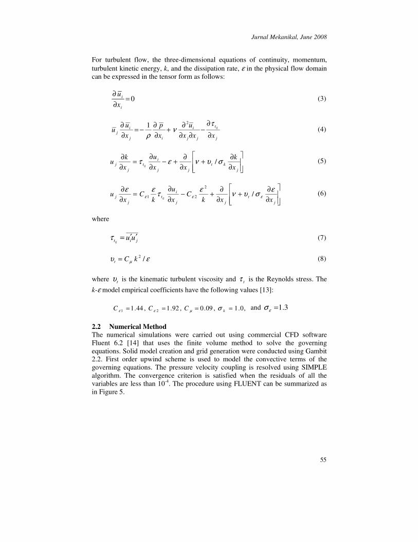
Figure 4: Computational mesh (a) Swirler, and (b) Combustion chamber
Jurnal Mekanikal, June 2008
55
For turbulent flow, the three-dimensional equations of continuity, momentum, turbulent kinetic energy, k, and the dissipation rate, ε in the physical flow domain can be expressed in the tensor form as follows:
0=∂∂
i
i
xu
(3)
j
t
jj
i
ij
ij xxx
uxp
xu
u ij
∂
∂−
∂∂∂+
∂∂−=
∂∂ τ
νρ
21 (4)
���
�
���
�
∂∂+
∂∂+−
∂∂
=∂∂
jkt
jj
it
jj x
kxx
uxk
uij
συνετ / (5)
���
�
���
�
∂∂+
∂∂+−
∂∂
=∂∂
jt
jj
it
jj xxk
Cxu
kC
xu
ij
εσυνετεεεεε /
2
21 ���
where jit uu
ij′′=τ (7)
ευ µ /2kCt = (8)
where tυ is the kinematic turbulent viscosity and tτ is the Reynolds stress. The
k-ε model empirical coefficients have the following values [13]:
,0.1,09.0,92.1,44.1 21 ==== kCCC σµεε and 3.1=εσ
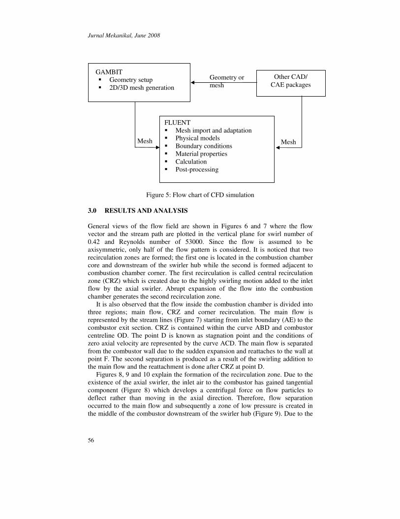
2.2 Numerical Method The numerical simulations were carried out using commercial CFD software Fluent 6.2 [14] that uses the finite volume method to solve the governing equations. Solid model creation and grid generation were conducted using Gambit 2.2. First order upwind scheme is used to model the convective terms of the governing equations. The pressure velocity coupling is resolved using SIMPLE algorithm. The convergence criterion is satisfied when the residuals of all the variables are less than 10-4. The procedure using FLUENT can be summarized as in Figure 5.
Jurnal Mekanikal, June 2008
56
Figure 5: Flow chart of CFD simulation
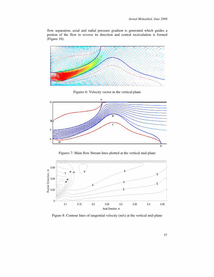
3.0 RESULTS AND ANALYSIS General views of the flow field are shown in Figures 6 and 7 where the flow vector and the stream path are plotted in the vertical plane for swirl number of 0.42 and Reynolds number of 53000. Since the flow is assumed to be axisymmetric, only half of the flow pattern is considered. It is noticed that two recirculation zones are formed; the first one is located in the combustion chamber core and downstream of the swirler hub while the second is formed adjacent to combustion chamber corner. The first recirculation is called central recirculation zone (CRZ) which is created due to the highly swirling motion added to the inlet flow by the axial swirler. Abrupt expansion of the flow into the combustion chamber generates the second recirculation zone.
It is also observed that the flow inside the combustion chamber is divided into three regions; main flow, CRZ and corner recirculation. The main flow is represented by the stream lines (Figure 7) starting from inlet boundary (AE) to the combustor exit section. CRZ is contained within the curve ABD and combustor centreline OD. The point D is known as stagnation point and the conditions of zero axial velocity are represented by the curve ACD. The main flow is separated from the combustor wall due to the sudden expansion and reattaches to the wall at point F. The second separation is produced as a result of the swirling addition to the main flow and the reattachment is done after CRZ at point D.
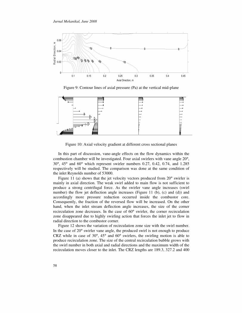
Figures 8, 9 and 10 explain the formation of the recirculation zone. Due to the existence of the axial swirler, the inlet air to the combustor has gained tangential component (Figure 8) which develops a centrifugal force on flow particles to deflect rather than moving in the axial direction. Therefore, flow separation occurred to the main flow and subsequently a zone of low pressure is created in the middle of the combustor downstream of the swirler hub (Figure 9). Due to the
GAMBIT � Geometry setup � 2D/3D mesh generation
FLUENT � Mesh import and adaptation � Physical models � Boundary conditions � Material properties � Calculation � Post-processing
Other CAD/ CAE packages
Mesh
Mesh
Geometry or mesh
Jurnal Mekanikal, June 2008
57
flow separation, axial and radial pressure gradient is generated which guides a portion of the flow to reverse its direction and central recirculation is formed (Figure 10).
Figures 6: Velocity vector in the vertical plane
Figures 7: Main flow Stream lines plotted at the vertical mid-plane
0.1 0.15 0.2 0.25 0.3 0.35 0.4 0.45
Axial Direction, m
0
0.02
0.04
0.06
Rad
ial D
irect
ion,
m
Figure 8: Contour lines of tangential velocity (m/s) at the vertical mid-plane
O
Jurnal Mekanikal, June 2008
58
0.1 0.15 0.2 0.25 0.3 0.35 0.4 0.45
Axial Direction, m
0
0.02
0.04
0.06
Rad
ial D
irect
ion,
m
Figure 9: Contour lines of axial pressure (Pa) at the vertical mid-plane
Figure 10: Axial velocity gradient at different cross sectional planes
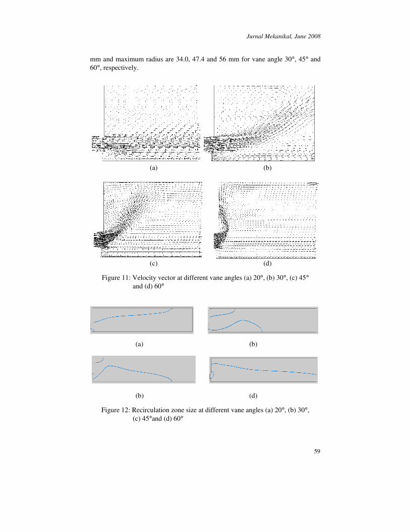
In this part of discussion, vane-angle effects on the flow dynamics within the combustion chamber will be investigated. Four axial swirlers with vane angle 20°, 30°, 45° and 60° which represent swirler numbers 0.27, 0.42, 0.74, and 1.285 respectively will be studied. The comparison was done at the same condition of the inlet Reynolds number of 53000.
Figure 11 (a) shows that the jet velocity vectors produced from 20° swirler is mainly in axial direction. The weak swirl added to main flow is not sufficient to produce a strong centrifugal force. As the swirler vane angle increases (swirl number) the flow jet deflection angle increases (Figure 11 (b), (c) and (d)) and accordingly more pressure reduction occurred inside the combustor core. Consequently, the fraction of the reversed flow will be increased. On the other hand, when the inlet stream deflection angle increases, the size of the corner recirculation zone decreases. In the case of 60° swirler, the corner recirculation zone disappeared due to highly swirling action that forces the inlet jet to flow in radial direction to the combustor corner.
Figure 12 shows the variation of recirculation zone size with the swirl number. In the case of 20° swirler vane angle, the produced swirl is not enough to produce CRZ while in case of 30°, 45° and 60° swirlers, the swirling motion is able to produce recirculation zone. The size of the central recirculation bubble grows with the swirl number in both axial and radial directions and the maximum width of the recirculation moves closer to the inlet. The CRZ lengths are 189.3, 327.2 and 400
Jurnal Mekanikal, June 2008
59
mm and maximum radius are 34.0, 47.4 and 56 mm for vane angle 30°, 45° and 60°, respectively.
(a) (b)
(c) (d)
Figure 11: Velocity vector at different vane angles (a) 20°, (b) 30°, (c) 45° and (d) 60°
(a) (b)
(b) (d)
Figure 12: Recirculation zone size at different vane angles (a) 20°, (b) 30°, (c) 45°and (d) 60°
Jurnal Mekanikal, June 2008
60
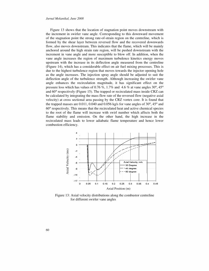
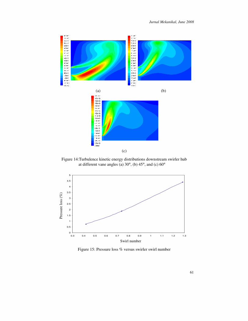
Figure 13 shows that the location of stagnation point moves downstream with the increment in swirler vane angle. Corresponding to this downward movement of the stagnation point the strong rate-of-strain region on the centreline, which is formed by the shear layer between reversed flow and the recovered downwards flow, also moves downstream. This indicates that the flame, which will be mainly anchored around the high strain rate region, will be pushed downstream with the increment in vane angle and more susceptible to blow off. In addition, when the vane angle increases the region of maximum turbulence kinetics energy moves upstream with the increase in its deflection angle measured from the centreline (Figure 14), which has a considerable effect on air fuel mixing processes. This is due to the highest turbulence region that moves towards the injector opening hole as the angle increases. The injection spray angle should be adjusted to suit the deflection angle of the turbulence strength. Although increasing the swirler vane angle enhances the recirculation magnitude, it has significant effect on the pressure loss which has values of 0.76 %, 1.7% and 4.6 % at vane angles 30°, 45° and 60° respectively (Figure 15). The trapped or recirculated mass inside CRZ can be calculated by integrating the mass flow rate of the reversed flow (negative axial velocity) at cross sectional area passing by the CRZ vortex core. It is found that the trapped masses are 0.011, 0.040 and 0.056 kg/s for vane angles of 30°, 45° and 60° respectively. This means that the recirculated heat and active chemical species to the root of the flame will increase with swirl number which affects both the flame stability and emission. On the other hand, the high increase in the recirculated mass leads to lower adiabatic flame temperature and hence lower combustion efficiency.
Figure 13: Axial velocity distributions along the combustor centreline for different swirler vane angles
Axi
al V
eloc
ity (m
s)
Axial Position (m)
Jurnal Mekanikal, June 2008
61
(a) (b)
(c)
Figure 14:Turbulence kinetic energy distributions downstream swirler hub
at different vane angles (a) 30°, (b) 45°, and (c) 60°
0
0.5
1
1.5
2
2.5
3
3.5
4
4.5
5
0.3 0.4 0.5 0.6 0.7 0.8 0.9 1 1.1 1.2 1.3
Swirl Number
Pre
ssur
e lo
ss %
Figure 15: Pressure loss % versus swirler swirl number
Swirl number
Pres
sure
loss
(%)
Jurnal Mekanikal, June 2008
62
4.0 CONCLUSIONS Swirling flow can increase combustor performance by aiding the fuel-air mixing process and by producing recirculation regions which can act as flame holders. Therefore, proper selection of a swirler is needed to reduce emissions and to enhance performance.
The variation in the swirler vane angle has a significant effect on the flow pattern inside the combustor. These can be concluded from the overall streamline pattern, the mean axial and tangential velocity distributions, and turbulence intensity near the inlet. As the swirl number increases, the length and the diameter of the central recirculation zone increases while the size of the corner recirculation decreases. Furthermore, the turbulence strength represented by the turbulence kinetics energy also increases, as well as trapped mass in the recirculation bubble. On the other hand, the increase in the swirl number results in more losses in the total pressure which will affect the combustion performances.
As observed from the analysis that have been done earlier, it can be concluded that the 60˚ vane angle swirler was able to produce the strongest circulation and highest recirculated mass flow inside the combustion chamber but on the contrary it has the disadvantages of the longest recirculation zone which makes the flame more susceptible to blow off and of the highest losses in total pressure.
In the light of this discussion, it can be argued that, the 45° vane angle swirler could be considered as a compromise between turbulence production and pressure losses.
REFERENCES
1. Pilavachi, P.A., 2002. Mini and micro-gas turbines for combined heat and power, Applied Thermal Engineering, 22, No. 18, 2003-2014.
2. Fuligno, L., Micheli, D. and Poloni, C., 2006. An Integrated Design Approach for Micro Gas Turbine Combustors: Preliminary 0-D and Simplified CFD Based Optimization, ASME Turbo Expo, Spain.
3. Cameretti, M. and Tuccillo, R., 2004. Comparing Different Solutions for the Micro-Gas Turbine Combustor, ASME Turbo Expo, Austria.
4. Lefebvre, A., 1983. Gas Turbine Combustion, McGraw-Hill, USA. 5. Collin, R. and Ward, J., 1990. Industrial Furnace Technology, Short Course,
Jld. I and II. Porto: Cenertec, Centro De Energia E Technologia, Portugal. 6. Beer, J.M. and Chigier, N.A, 1972. Combustion Aerodynamics, Applied
Science Publishers, London. 7. Thring, M.W. et al., 1971. The Aerodynamics of Annular Jet Registers, Paper
presented at 2nd Members Conference, IFRF, Ijmuiden, Holland. 8. Mellor, A.M., 1990. Design of Modern Gas Turbine Combustors, Academic
Press. 9. Drake, P.F. and Hubard, E.H., 1963. Effect of air swirl on the completeness of
combustion, J. Inst. Fuel, 36:389. 10. Claypole, T.C. and Syred, N., 1981. The Effect of Swirl Burner
Aerodynamics on NOx Formation, Eighteenth International Symposium on Combustion, 8, 81-89.
Jurnal Mekanikal, June 2008
63
11. Mestre, A., 1974. Efficiency and Pollutant Formation Studies in a Swirling Flow Combustor, Fluid Mechanics of Combustion, Edited by Dussord et al., ASME, New York.
12. Chigier, N.A., 1987. Progress in Energy and Combustion Science, 4, Oxford, Pergamon Press, UK.
13. Yakhot, A. and Orszag, S., 1986. Renormalisation Group Analysis of Turbulence: I, Basic Theory, Journal of Scientific Computing, 1, No. 1, 3-51.
14. FLUENT 6.2 User's Guide, Fluent Inc. 2005.