preface, contents product overview - telemark...
TRANSCRIPT
�
Preface, Contents
Product Overview 1
Installation and Authorization 2Designing a Sequential ControlSystem Based on the Exampleof a Drill
3
Working with an S7 Graph 4
Creating a Project 5Programming the Structure of aSequencer 6Programming Actions andConditions 7
Saving and Compiling 8S7 Graph FB ParameterAssignment and Call 9Downloading the S7 Graph-FBand Instance-DB 10Monitoring and Testing theSequential Control System 11
Printing the Sequencer 12
Overview of all Actions 13
Configuration Instructions 14
Instance DB 15Glossary, Index
SIMATIC
S7 Graph V5.1 for S7-300/400Programming SequentialControl Systems
Manual
This manual has the order number:6ES7 811-0CC04-8BA0
Edition 05/2001A5E00105265-01
Copyright © Siemens AG 2001 All rights reserved
The reproduction, transmission or use of this document or itscontents is not permitted without express written authority.Offenders will be liable for damages. All rights, including rightscreated by patent grant or registration of a utility model or design,are reserved.
Siemens AGBereich Automatisierungs- und AntriebstechnikGeschaeftsgebiet Industrie-AutomatisierungssystemePostfach 4848, D- 90327 Nuernberg
Disclaimer of Liability
We have checked the contents of this manual for agreement withthe hardware and software described. Since deviations cannot beprecluded entirely, we cannot guarantee full agreement. However,the data in this manual are reviewed regularly and any necessarycorrections included in subsequent editions. Suggestions forimprovement are welcomed.
©Siemens AG 2001Technical data subject to change.
Siemens Aktiengesellschaft 6ES7 811-0CC04-8BA0
Safety Guidelines
This manual contains notices intended to ensure personal safety, as well as to protect the products and
connected equipment against damage. These notices are highlighted by the symbols shown below and
graded according to severity by the following texts:
! Dangerindicates that death, severe personal injury or substantial property damage will result if properprecautions are not taken.
! Warningindicates that death, severe personal injury or substantial property damage can result if properprecautions are not taken.
! Cautionindicates that minor personal injury can result if proper precautions are not taken.
Cautionindicates that property damage can result if proper precautions are not taken.
Noticedraws your attention to particularly important information on the product, handling the product, or to aparticular part of the documentation.
Qualified Personnel
Only qualified personnel should be allowed to install and work on this equipment. Qualified persons are
defined as persons who are authorized to commission, to ground and to tag circuits, equipment, and
systems in accordance with established safety practices and standards.
Correct Usage
Note the following:
!WarningThis device and its components may only be used for the applications described in the catalog or the
technical description, and only in connection with devices or components from other manufacturers
which have been approved or recommended by Siemens.
This product can only function correctly and safely if it is transported, stored, set up, and installedcorrectly, and operated and maintained as recommended.
Trademarks
SIMATIC®, SIMATIC HMI® and SIMATIC NET® are registered trademarks of SIEMENS AG.
Third parties using for their own purposes any other names in this document which refer to trademarks might
infringe upon the rights of the trademark owners.

S7 Graph for S7-300/400 Programming Sequential Control SystemsA5E00105265-01 iii
Preface
Purpose of the ManualThis manual provides you with a complete overview of programming withS7 Graph. It supports you during the installation and setting up of the software. Itincludes explanations of how to create a program, the structure of user programs,and the individual language elements.
The manual is intended for persons with the appropriate qualifications who areinvolved in programming, configuration, commissioning, and service ofprogrammable logic controllers.
We recommend that you familiarize yourself with the example in Chapter 3"Designing a Sequential Control System Based on the Example of a Drill". This willhelp you to get to know S7 Graph quickly.
Required ExperienceTo understand the manual, you should have general experience of automationengineering.
You should also be familiar with working on computers or PC-type machines (forexample programming devices with the Windows 95/98/2000 or NT operatingsystems. Since S7 Graph uses the STEP 7 platform, you should also be familiarwith working with the standard software described in the "Programming withSTEP 7 V5.1" manual.
Scope of the ManualThe manual is valid for the S7 Graph V5.1 software package.
05.04.2001
Preface
S7 Graph for S7-300/400 Programming Sequential Control Systemsiv A5E00105265-01
Documentation Packages for S7 Graph and the STEP 7 Standard Software
The following table provides you with an overview of the STEP 7 and S7 Graphdocumentation:
Manuals Purpose Order Number
S7-SCL V5.1 for S7-300/400 Basic and reference informationexplaining how to create aprogram, the structure of userprograms and the individuallanguage elements.
6ES7 811-0CC04-8BA0
Basics of STEP 7:
• Getting Started and Exercises withSTEP 7 V5.1
• Programming with STEP 7 V5.1
• Configuring Hardware andConnections withSTEP 7 V5.1
• Converting from S5 to S7
The basics for technicalpersonnel describing how toimplement control tasks withSTEP 7 and S7-300/400.
6ES7810-4CA05-8BA0
STEP 7 reference:
• LAD/FBD/STL manualsfor S7-300/400
• Standard and System Functionsfor S7-300/400
Reference work describing theLAD, FBD and STL programminglanguages as well as standardand system functions as asupplement to the STEP 7 basics.
6ES7810-4CA05-8BR0
05.04.2001

Preface
S7 Graph for S7-300/400 Programming Sequential Control SystemsA5E00105265-01 v
Manual and Online HelpThis manual is an extract from the Online Help. The manual describes the basicknowledge you require to work with S7 Graph. The online help contains detailed,step-by-step instructions and reference sections. Since the manual and online helphave the same structure, you can change easily between manual and online help.
Access to Online HelpThe help system is integrated in the software with several interfaces:
• The Help menu provides numerous menu commands: Contents opens thecontents of the S7 Graph help system. Introduction provides an overview ofprogramming with S7 Graph. Using Help provides detailed instructions onworking with the online help system.
• The context-sensitive help system provides information about the currentcontext, for example help on an open dialog box or active window. This can bedisplayed by clicking the "Help" button or pressing the F1 key.
• The status bar is another form of context-sensitive help. A brief explanation ofeach menu command is displayed here when you position the mouse pointeron a menu command.
• A brief explanation of the buttons in the toolbar is also displayed if you positionthe mouse pointer briefly over a button.
If you prefer to have a printout of the information in the online help system, you canprint individual topics, books or the entire help system.
Documentation Reply FormTo provide you and future S7 Graph users with the best possible documentation,we need your support. If you have comments about this manual or the online help,please fill out the questionnaire at the end of this manual and send it the addressshown. Please take the time to add your own evaluation grade.
Training CentersSiemens offers a number of training courses to familiarize you with the SIMATICS7 automation system. Please contact your regional training center or our centraltraining center in D 90327 Nuremberg, Germany for details:Telephone: +49 (911) 895–3200.
http://www.ad.siemens.de/training
05.04.2001

Preface
S7 Graph for S7-300/400 Programming Sequential Control Systemsvi A5E00105265-01
SIMATIC Documentation on the Internet / IntranetYou will find the documentation on the internet at:
http://www.ad.siemens.de/support
Use the Knowledge Manager to find the documentation you need quickly. If youhave any questions or suggestions concerning the documentation you can use the"Documentation" conference in the internet forum.
Visit the SIMATIC documentation homepage. Here you can find out about newproducts and innovations, ask questions concerning the documentation and giveus your suggestions, criticism, praise or requests.
http://intra1.khe.siemens.de/e8_doku/index.htm
05.04.2001

Preface
S7 Graph for S7-300/400 Programming Sequential Control SystemsA5E00105265-01 vii
Automation and Drives, Service & SupportAvailable worldwide, around the clock:
Johnson City
Nuremberg
Singapore
SIMATIC Basic Hotline
Worldwide (Nuremberg)Technical Support
Worldwide (Nuremberg)Technical Support
(Free Contact)
Local time: Mo.-Fr. 7:00 to 17:00
Phone: +49 (180) 5050 222
Fax: +49 (180) 5050 223
E-mail: [email protected]
GMT: +1:00
(charged, only withSIMATIC Card)Local time: Mo.-Fr. 0:00 to 24:00
Phone: +49 (911) 895-7777
Fax: +49 (911) 895-7001GMT: +01:00
Europe / Africa (Nuremberg)Authorization
America (Johnson City)Technical Support andAuthorization
Asia / Australia (Singapore)
Technical Support andAuthorization
Local time: Mo.-Fr. 7:00 to 17:00
Phone: +49 (911) 895-7200
Fax: +49 (911) 895-7201
E-mail: [email protected]
GMT: +1:00
Local time: Mo.-Fr. 8:00 to 19:00
Phone: +1 423 461-2522
Fax: +1 423 461-2289
E-mail: [email protected]
GMT: -5:00
Local time: Mo.-Fr. 8:30 to 17:30
Phone: +65 740-7000
Fax: +65 740-7001
E-mail: [email protected]
GMT: +8:00
German and English are spoken on all the SIMATIC hotlines, French, Italian and Spanish are also spoken on the
authorization hotline.
05.04.2001

Preface
S7 Graph for S7-300/400 Programming Sequential Control Systemsviii A5E00105265-01
Service & Support on the InternetIn addition to our documentation, we offer our Know-how online on the internet at:
http://www.ad.siemens.de/support
where you will find the following:
• Current Product Information leaflets, FAQs (Frequently Asked Questions),Downloads, Tips and Tricks.
• A newsletter giving you the most up-to-date information on our products.
• The Knowledge Manager helps you find the documents you need.
• Users and specialists from all over the world share information in the forum.
• Your local customer service representative for Automation & Drives in ourcustomer service representative data bank.
• Information on field service, repairs, spare parts and more under "Services".
05.04.2001
S7 Graph for S7-300/400 Programming Sequential Control SystemsA5E00105265-01 ix
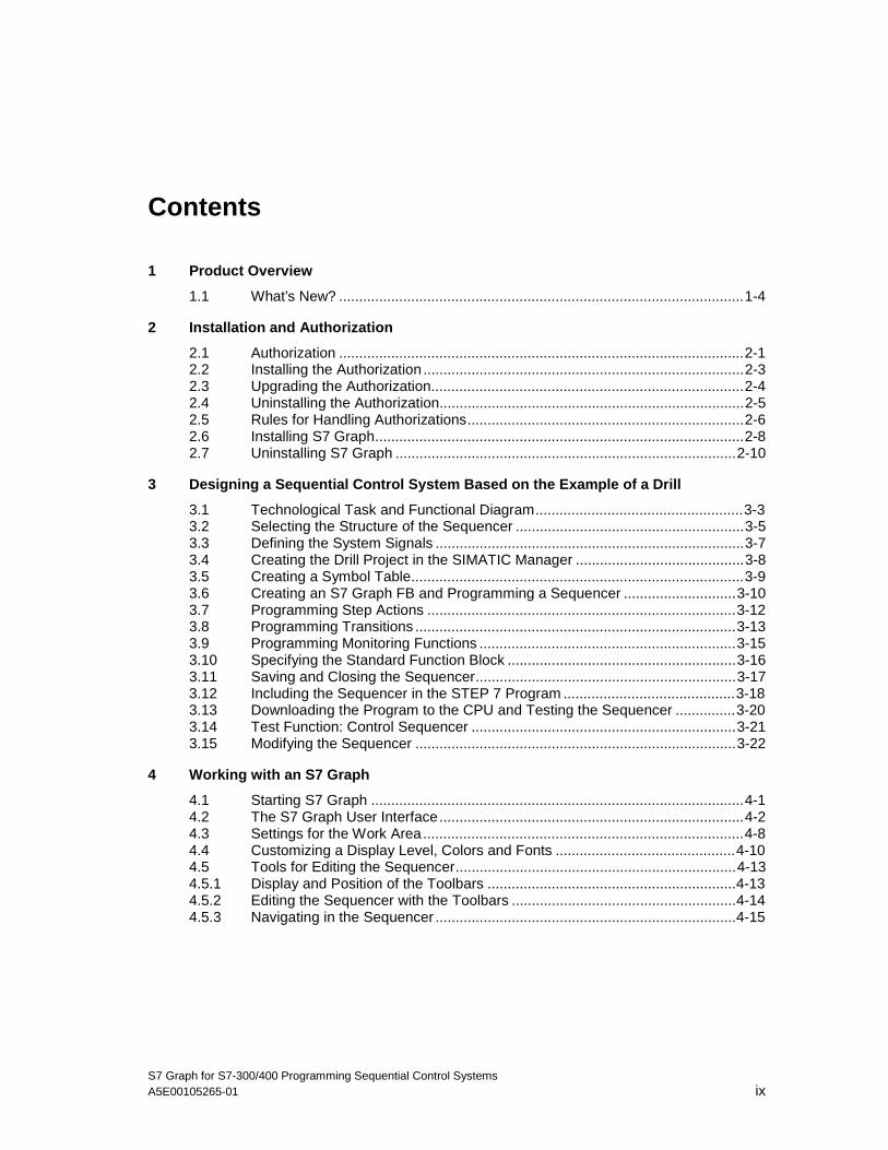
Contents
1 Product Overview
1.1 What’s New? .....................................................................................................1-4
2 Installation and Authorization
2.1 Authorization .....................................................................................................2-12.2 Installing the Authorization ................................................................................2-32.3 Upgrading the Authorization..............................................................................2-42.4 Uninstalling the Authorization............................................................................2-52.5 Rules for Handling Authorizations.....................................................................2-62.6 Installing S7 Graph............................................................................................2-82.7 Uninstalling S7 Graph .....................................................................................2-10
3 Designing a Sequential Control System Based on the Example of a Drill
3.1 Technological Task and Functional Diagram....................................................3-33.2 Selecting the Structure of the Sequencer .........................................................3-53.3 Defining the System Signals .............................................................................3-73.4 Creating the Drill Project in the SIMATIC Manager ..........................................3-83.5 Creating a Symbol Table...................................................................................3-93.6 Creating an S7 Graph FB and Programming a Sequencer ............................3-103.7 Programming Step Actions .............................................................................3-123.8 Programming Transitions ................................................................................3-133.9 Programming Monitoring Functions ................................................................3-153.10 Specifying the Standard Function Block .........................................................3-163.11 Saving and Closing the Sequencer.................................................................3-173.12 Including the Sequencer in the STEP 7 Program ...........................................3-183.13 Downloading the Program to the CPU and Testing the Sequencer ...............3-203.14 Test Function: Control Sequencer ..................................................................3-213.15 Modifying the Sequencer ................................................................................3-22
4 Working with an S7 Graph
4.1 Starting S7 Graph .............................................................................................4-14.2 The S7 Graph User Interface............................................................................4-24.3 Settings for the Work Area................................................................................4-84.4 Customizing a Display Level, Colors and Fonts .............................................4-104.5 Tools for Editing the Sequencer......................................................................4-134.5.1 Display and Position of the Toolbars ..............................................................4-134.5.2 Editing the Sequencer with the Toolbars ........................................................4-144.5.3 Navigating in the Sequencer ...........................................................................4-15
05.04.0105.04.200105.04.2001

Contents
S7 Graph for S7-300/400 Programming Sequential Control Systemsx A5E00105265-01
5 Creating a Project
5.1 Creating the Project in the SIMATIC Manager..................................................5-15.2 S7 Graph FB or S7 Graph Source File? ...........................................................5-25.3 S7 Graph FB .....................................................................................................5-35.4 S7 Graph Source File........................................................................................5-35.5 Opening an S7 Graph FB or an S7 Graph Source File.....................................5-4
6 Programming the Structure of a Sequencer
6.1 Sequencer - Principle........................................................................................6-26.2 Structures of a Sequencer ................................................................................6-36.3 Rules for the Structure of a Sequencer.............................................................6-46.4 Elements of a Sequencer..................................................................................6-56.5 Step-Transition Pair and Initial Step..................................................................6-56.6 Jump..................................................................................................................6-66.7 Alternative Branch.............................................................................................6-76.8 Simultaneous Branch ........................................................................................6-86.9 Branch Stop.......................................................................................................6-96.10 New Sequencer.................................................................................................6-96.11 Permanent Instructions ...................................................................................6-106.12 Block Comment...............................................................................................6-11
7 Programming Actions and Conditions
7.1 Actions...............................................................................................................7-37.2 Standard Actions...............................................................................................7-47.3 Event-Dependent Actions .................................................................................7-67.4 Counters, Timers, and Arithmetic in Actions.....................................................7-97.5 Conditions .......................................................................................................7-147.6 Ladder Logic Elements for Programming Conditions .....................................7-187.7 Logic Operations with Ladder Logic Elements................................................7-207.8 FBD Elements for Programming Conditions ...................................................7-227.9 S7 Graph Addresses in Conditions.................................................................7-257.10 Supervision Errors and Acknowledgment .......................................................7-267.11 Comment, Extended Name, Number, Name ..................................................7-287.12 Programming with Symbolic Addresses .........................................................7-297.13 Editing Variables .............................................................................................7-30
8 Saving and Compiling
8.1 Saving and Compiling .......................................................................................8-18.2 Rules for Saving an S7 Graph FB.....................................................................8-28.3 Rules for Saving an S7 Graph Source File .......................................................8-28.4 Settings for Saving and Compiling ....................................................................8-38.4.1 Settings in the "General" Tab............................................................................8-48.4.2 Settings in the "Compile/Save" Tab: FB Parameters........................................8-68.4.3 Settings in the "Compile/Save" Tab: Executability............................................8-78.4.4 Settings in the "Compile/Save" Tab: Interface Description...............................8-88.4.5 Settings in the "Compile/Save" Tab: Sequencer Properties .............................8-98.4.6 Settings in the "Compile/Save" Tab: Warnings...............................................8-108.4.7 Settings in the "Messages" Tab ......................................................................8-108.5 Saving .............................................................................................................8-118.6 Compiling ........................................................................................................8-14
05.04.0105.04.200105.04.2001
Contents
S7 Graph for S7-300/400 Programming Sequential Control SystemsA5E00105265-01 xi
9 S7 Graph FB Parameter Assignment and Call
9.1 Calling the S7 Graph FB in the S7 Program.....................................................9-19.2 Calling the S7 Graph FB ...................................................................................9-29.3 Selecting an FB Parameter Set.........................................................................9-39.4 Parameter Sets of the FB..................................................................................9-49.5 Input Parameters of the S7 Graph FB ..............................................................9-69.6 Output Parameters of the S7 Graph FB............................................................9-99.7 The Modes of the Sequential Control System ................................................9-109.7.1 Automatic Mode (SW_AUTO).........................................................................9-119.7.2 Manual mode (SW_MAN) ...............................................................................9-129.7.3 Inching mode (SW_TAP) ................................................................................9-139.7.4 Automatic or Switch to Next Mode (SW_TOP) ...............................................9-149.7.5 Selecting a Step with S_SEL ..........................................................................9-159.7.6 Selecting a Step with S_PREV or S_NEXT....................................................9-159.7.7 Progressing to the next Step with T_PUSH....................................................9-16
10 Downloading the S7 Graph-FB and Instance-DB
10.1 Downloading Blocks from the Programming Device to the CPU....................10-110.2 Uploading Blocks from the CPU to the Programming Device.........................10-3
11 Monitoring and Testing the Sequential Control System
11.1 Monitoring and Test Functions in the S7 Graph .............................................11-211.1.1 Monitoring the Status Information ...................................................................11-211.1.2 Control Sequencer ..........................................................................................11-411.1.3 Synchronization...............................................................................................11-411.2 Test Functions of STEP 7 ...............................................................................11-5
12 Printing the Sequencer
13 Overview of all Actions
13.1 Standard Actions with and without Interlock ...................................................13-113.2 Event-Dependent Actions - with and without Interlock ...................................13-213.3 Counters in Actions .......................................................................................13-1013.4 Timers in Actions...........................................................................................13-1613.5 Arithmetic in Actions......................................................................................13-22
14 Configuration Instructions
14.1 General Level and Program Structure ............................................................14-214.2 Points to Note about Programming Sequencers.............................................14-814.3 Linking to Operator Control and Monitoring Systems ...................................14-12
05.04.0105.04.200105.04.2001
Contents
S7 Graph for S7-300/400 Programming Sequential Control Systemsxii A5E00105265-01
15 Instance DB
15.1 Settings for the Instance DB ...........................................................................15-115.2 Assignment of Instance DB and S7 Graph FB................................................15-215.3 Automatic Creation of the Instance DB on Saving..........................................15-315.4 Creating the Instance DB Later.......................................................................15-315.5 Displaying and Printing the Content of the Instance DB.................................15-315.6 Accessing the Instance DB .............................................................................15-415.7 Structure of an Instance DB............................................................................15-415.8 Outline of the Structure of the Instance DB ....................................................15-415.9 FB Parameters ................................................................................................15-515.10 The Transition Structure..................................................................................15-915.11 The Step Structure ........................................................................................15-1115.12 Sequencer Status..........................................................................................15-1315.13 Internal Data Area .........................................................................................15-18
Glossary
Index
05.04.0105.04.200105.04.2001
S7 Graph for S7-300/400 Programming Sequential Control SystemsA5E00105265-01 1-1
1 Product Overview
S7 Graph Programming Language
The S7 Graph programming language extends the range of functions of STEP 7 byallowing you to program sequential control systems graphically.
With S7 Graph, you can configure and write programs to control sequentialprocesses with a SIMATIC programmable logic controller (PLC). The process isdivided into single steps with a clearly defined range of functions. The processsequence is represented graphically and can be documented both as graphics andtext.
In the steps, you specify the actions to be executed. The progression from one stepto the next is controlled by transitions (step enabling conditions). The definitions,interlocks and monitoring of the transitions are programmed using a subset of theLadder Logic (LAD) or FBD (Function Block Diagram) programming languages.
S7 Graph for the S7-300/400 complies with the sequential control language"Sequential Function Chart" specified in the DIN EN 61131-3 (IEC 1131-3)standard.
05.04.0105.04.200105.04.2001
Product Overview
S7 Graph for S7-300/400 Programming Sequential Control Systems1-2 A5E00105265-01
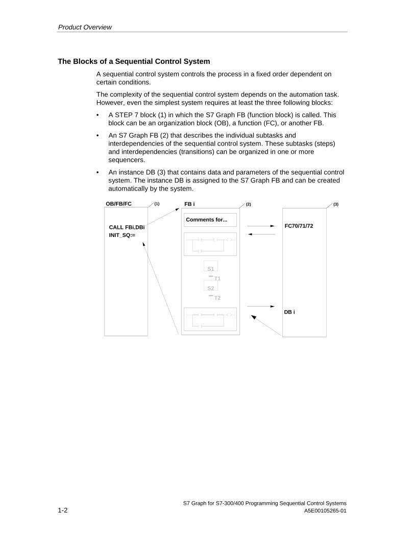
The Blocks of a Sequential Control System
A sequential control system controls the process in a fixed order dependent oncertain conditions.
The complexity of the sequential control system depends on the automation task.However, even the simplest system requires at least the three following blocks:
• A STEP 7 block (1) in which the S7 Graph FB (function block) is called. Thisblock can be an organization block (OB), a function (FC), or another FB.
• An S7 Graph FB (2) that describes the individual subtasks andinterdependencies of the sequential control system. These subtasks (steps)and interdependencies (transitions) can be organized in one or moresequencers.
• An instance DB (3) that contains data and parameters of the sequential controlsystem. The instance DB is assigned to the S7 Graph FB and can be createdautomatically by the system.
OB/FB/FC
FC70/71/72
T2
T1
S2
S1
Comments for...
FB i(1)
CALL FBi,DBiINIT_SQ:=
(2) (3)
DB i
05.04.0105.04.200105.04.2001
Product Overview
S7 Graph for S7-300/400 Programming Sequential Control SystemsA5E00105265-01 1-3
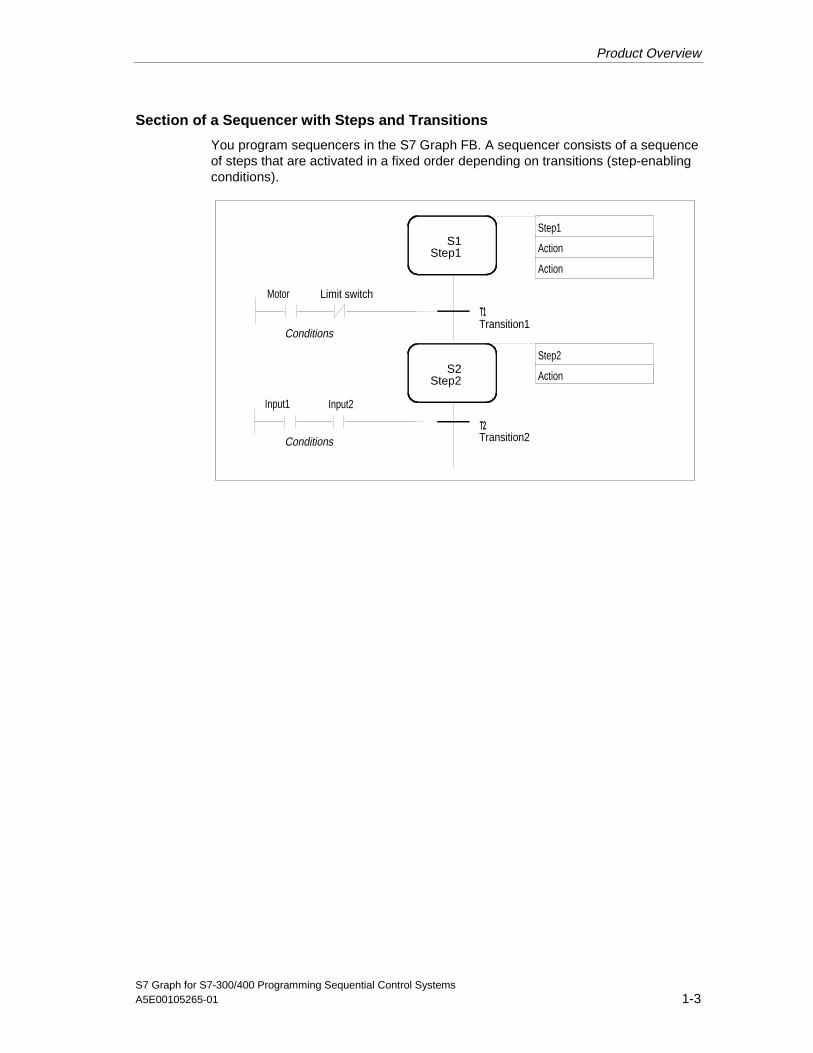
Section of a Sequencer with Steps and Transitions
You program sequencers in the S7 Graph FB. A sequencer consists of a sequenceof steps that are activated in a fixed order depending on transitions (step-enablingconditions).
Motor Limit switch
S1Step1
T1
Step1
Action
S2Step2
Step2
Action
T2
Input1 Input2
Conditions
Action
Transition1
Transition2
Conditions
05.04.0105.04.200105.04.2001

Product Overview
S7 Graph for S7-300/400 Programming Sequential Control Systems1-4 A5E00105265-01
1.1 What’s New?
Version 5.1 of the S7 Graph programming software has the following extendedfunctions and modifications compared with Version 5.0:
PLCopen Basis Level
S7 Graph V5.1 complies with the PLCopen Basis Level for sequential controlsystems as stipulated in the DIN EN 61131-3 standard.
If you have a sequential control system that conforms with the standard, you cannow import it into the STEP 7 data management as an ASCII file using theSIMATIC Manager and then edit it in S7 Graph.
To create sequential control systems complying with the standard, select the"Application Settings" dialog box and activate the "IEC-compliant" in the "General"tab.
Compiler Expansions
• Minimizing the memory requirements for the S7 Graph FBYou can reduce the memory required by the S7 Graph FB considerably byselecting the compilation option "Interface Description: Memory minimized" andusing the new standard function FC73.
• Safe activation mode:There is now a new compilation option known as "Safe activation mode". Thishas the effect that when a step is activated, the system locates and deactivatesall steps that cannot be active at the same time as the step being activated dueto the sequencer structure.
• Checking the standard functions used:When you compile, the compiler checks whether the FC used is adequate toexecute the functions used in the sequencer. If the FC is not adequate, acompilation error is indicated.
• Expanded block information:When you compile a block, the compiler checks whether the block uses theextended functionality of the current S7 Graph version or only the restrictedfunctionality from previous versions. You can see this information in the fileproperties (menu command File > Properties).
05.04.0105.04.200105.04.2001
Product Overview
S7 Graph for S7-300/400 Programming Sequential Control SystemsA5E00105265-01 1-5
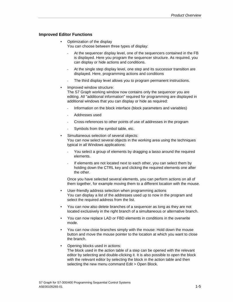
Improved Editor Functions
• Optimization of the displayYou can choose between three types of display:
- At the sequencer display level, one of the sequencers contained in the FBis displayed. Here you program the sequencer structure. As required, youcan display or hide actions and conditions.
- At the single step display level, one step and its successor transition aredisplayed. Here, programming actions and conditions
- The third display level allows you to program permanent instructions.
• Improved window structure:The S7 Graph working window now contains only the sequencer you areediting. All "additional information" required for programming are displayed inadditional windows that you can display or hide as required:
- Information on the block interface (block parameters and variables)
- Addresses used
- Cross-references to other points of use of addresses in the program
- Symbols from the symbol table, etc.
• Simultaneous selection of several objects:You can now select several objects in the working area using the techniquestypical in all Windows applications:
- You select a group of elements by dragging a lasso around the requiredelements.
- If elements are not located next to each other, you can select them byholding down the CTRL key and clicking the required elements one afterthe other.
Once you have selected several elements, you can perform actions on all ofthem together, for example moving them to a different location with the mouse.
• User-friendly address selection when programming actionsYou can display a list of the addresses used up to now in the program andselect the required address from the list.
• You can now also delete branches of a sequencer as long as they are notlocated exclusively in the right branch of a simultaneous or alternative branch.
• You can now replace LAD or FBD elements in conditions in the overwritemode.
• You can now close branches simply with the mouse: Hold down the mousebutton and move the mouse pointer to the location at which you want to closethe branch.
• Opening blocks used in actions:The block used in the action table of a step can be opened with the relevanteditor by selecting and double-clicking it. It is also possible to open the blockwith the relevant editor by selecting the block in the action table and thenselecting the new menu command Edit > Open Block.
05.04.0105.04.200105.04.2001

Product Overview
S7 Graph for S7-300/400 Programming Sequential Control Systems1-6 A5E00105265-01
Other New Features
• New system function: FC73A new system function is supplied with the package allowing you to reduce thememory requirements of the S7 Graph FB considerably. Due to its size of lessthan 8 Kbytes, FC73 can also be processed by smaller CPUs.
FC73 provides the functionality of S7 Graph V5.0. However, the followingrestrictions apply: The blocks created do not have diagnostic capability.Visualization of the blocks is also restricted.
• New versions of FC70/FC71S7 Graph blocks that use arithmetic or word instructions in actions can now beoperated with the FC70 and FC71 system functions.
• Setting the address priorityIn the SIMATIC Manager, you can decide whether the symbol or the absolutevalue has priority when blocks are opened following modifications in thesymbol table. This setting is possible from STEP 7 V5.0 onwards, it alsoapplies to S7 Graph blocks from S7 Graph V5.1 onwards.
• Limiting the maximum number of status jobs usedYou can also specify the maximum number of status jobs for S7 Graph. Youmake this setting in the "General" tab (application settings). Limiting thenumber of status jobs can be useful if you are working with a smaller CPU andwant a status display for several applications at the same time.
05.04.0105.04.200105.04.2001
S7 Graph for S7-300/400 Programming Sequential Control SystemsA5E00105265-01 2-1
2 Installation and Authorization
2.1 Authorization
A product authorization is required to use the S7 Graph software package.Software protected by this mechanism can only be used when the authorizationrequired by the program or software package is detected on the hard disk of theprogramming device.
Different authorizations are necessary, for example for STEP 7 and for the optionalpackages.
Authorization Diskette
To authorize the product, you require the copy-protected authorization disketteshipped with the package. This contains the actual authorization. The "AuthorsW"program required to display, install, and uninstall the authorization is on theinstallation CD-ROM that also contains S7 Graph.
Number of Authorizations
The number of possible authorizations depends on an authorization counter on theauthorization diskette. When you install an authorization, the counter isdecremented by 1. Once the counter reaches the value 0, there are no moreauthorizations on the diskette.
Note
You receive a yellow authorization diskette for the STEP 7 standard software witha corresponding authorization. You do not need an authorization for STEP 7 Mini.
With each optional software package, you receive a red authorization diskettecontaining one authorization.
05.04.0105.04.200105.04.2001

Installation and Authorization
S7 Graph for S7-300/400 Programming Sequential Control Systems2-2 A5E00105265-01
Loss of the Authorization...
You can lose an authorization, for example, due to a defect on the hard disk thatprevents you from uninstalling the authorization from the defective hard disk.
If you lose the authorization, you can use the emergency authorization. This is alsoon the authorization diskette. The emergency authorization allows you to continueto use the software for a restricted time. In this case, when you start S7 Graph, thetime until the authorization expires is displayed. Before this time expires, youshould obtain a replacement for the lost authorization from your Siemens distributoror sales office.
Caution
The restricted period of the emergency authorization begins from the moment youinstall it, even if you do not start S7 Graph. You cannot extend this period even bytransferring the authorization back to the diskette.
Installing AuthorsW
The "AuthorsW" program required to display, install, and uninstall the authorizationis on the same CD-ROM as S7 Graph V5.0. You can install this program on yourhard disk and start it there when you want to install and uninstall authorizations.
Note
The default location for the AuthorsW program is the AuthorsW folder and you canstart it from the taskbar (START > SIMATIC > AuthorsW > AuthorsW).
05.04.0105.04.200105.04.2001
Installation and Authorization
S7 Graph for S7-300/400 Programming Sequential Control SystemsA5E00105265-01 2-3
2.2 Installing the Authorization
Handling the Authorization During Installation
You should transfer the authorization when prompted by Setup when you installS7 Graph for the first time. Follow the steps below:
1. Insert the authorization diskette when Setup asks you for it.
2. Then confirm the next prompt.
3. The authorization is transferred to a physical drive.
Installing the Authorization Later
If you start the S7 Graph software and there is no authorization on your system, amessage to this effect is displayed. To install the authorization at a later point intime:
1. Insert the authorization diskette in your floppy disk drive, for example, drive A.
2. Start the "Authorsw.exe" program on the hard disk drive.
3. Select drive A:\. The authorizations on the authorization diskette are displayed.
4. Select the full authorization for S7 Graph (validity: unlimited).
5. Holding down the left mouse button, drag the selected authorization to thedestination drive. The authorization is transferred to the destination drive.
Caution
The authorization is effective in Windows NT only when full access to both harddisk "C:" and the source drive is possible.
Recovering the Authorization
If you have a problem with your authorization (defective etc.), please contact thehotline. If a problem occurs, it may be possible to avoid loss of the authorizationusing the menu command Authorization > Recover.
05.04.0105.04.200105.04.2001
Installation and Authorization
S7 Graph for S7-300/400 Programming Sequential Control Systems2-4 A5E00105265-01
2.3 Upgrading the Authorization
Use the "Upgrade" menu command to upgrade authorizations. To use this function,you require:
1. The authorization diskette of the authorization you want to upgrade
2. The latest version of the "AuthorsW" authorization program on the hard disk
3. The new S7 Graph upgrade on diskette
4. The old authorization on diskette or hard disk
When you upgrade, the old authorizations are deleted and replaced by new ones.For this reason, the authorization diskette must never be made read-only.
1. Insert the new authorization diskette.
2. Start the "Authorsw.exe" program on the hard disk drive.
3. Select the menu command Authorization > Upgrade. A dialog box is opened.Select the upgrade program in the dialog box. You will then be asked to insertthe authorization diskette of the old authorization.
4. Insert the required authorization diskette. You will then be asked whether youreally want to upgrade. This is the last opportunity to cancel the upgrade. Afteryou confirm this prompt, do not interrupt the upgrade procedure under anycircumstances otherwise you will lose the authorization.
5. After clicking the OK button, you will be prompted to insert the authorizationdiskette with the new authorization.
All the necessary requirements are checked. If these requirements are met, theupgrade is completed by activating the new authorization.
05.04.0105.04.200105.04.2001
Installation and Authorization
S7 Graph for S7-300/400 Programming Sequential Control SystemsA5E00105265-01 2-5
2.4 Uninstalling the Authorization
If, for example, you want to reformat the hard disk containing the authorization, youmust first transfer the authorizations back to the authorization diskette (uninstall).You require the yellow original authorization diskette of the STEP 7 standardsoftware. You can also transfer the authorizations of the optional packages you areusing back to this authorization diskette.
To transfer the authorization back to the authorization diskette:
1. Insert the yellow original authorization diskette in your floppy disk drive, forexample, drive A.
2. Start the "Authorsw.exe" program on the hard disk drive.
3. Select the drive on which your authorization is located. All the authorizationsfound on this drive are displayed.
4. Select the relevant authorization.
5. Holding down the left mouse button, drag the selected authorization to driveA:\. The authorization is transferred to the authorization diskette.
6. Close the dialog box if you do not want to remove any further authorizations.You can use this diskette again to install the authorization.
05.04.0105.04.200105.04.2001

Installation and Authorization
S7 Graph for S7-300/400 Programming Sequential Control Systems2-6 A5E00105265-01
2.5 Rules for Handling Authorizations
Caution
Read the instructions in this section and in the README.WRI file on theauthorization diskette. If you do not keep to the instructions in this file, you maydestroy the authorization.
When is it necessary to uninstall authorizations?
Before you format, compress, or restore your hard disk drive, or before you install anew operating system, you must first uninstall existing authorizations.
Backup
If a backup of your hard disk contains copies of your authorizations, there is a riskthat the valid, installed authorizations will be overwritten and destroyed when youwrite the backup data to the hard disk.
To avoid loss of the authorization by overwriting an authorized system with abackup:
• Either remove all authorizations before you make your backup
• Or exclude the authorizations from the backup.
Hard Disk Optimization
If you use an optimization program that allows fixed blocks to be moved on thehard disk, you should only use this function after first transferring all authorizationsfrom the hard disk back to the authorization diskette.
Defective Sectors
After installing an authorization, a special cluster is created on the hard disk that issometimes indicated as "defective". Do not attempt to repair this. Otherwise, youwill destroy the authorization.
Read-Only and Copy Protection
The authorization diskette must not be made read-only.
Files on the authorization diskette can be copied to a different drive (for examplehard disk) and used there. It is, however, not possible to install an authorizationwith the copied data; this is only possible with the original authorization diskette.
05.04.0105.04.200105.04.2001
Installation and Authorization
S7 Graph for S7-300/400 Programming Sequential Control SystemsA5E00105265-01 2-7
Permitted Drives
The authorization can only be installed on a hard disk drive. If you have acompressed drive (for example DBLSPACE), you can install on its host drive.
The authorization tool prevents installation on unsuitable drives.
Location
When you install an authorization, the files are transferred to the protected folder"AX NF ZZ" with the attributes "system" and "hidden".
• Do not change these attributes.
• The files must not be modified or deleted.
• The folder must not be moved. Files copied from the folder (authorizations) aredetected as invalid authorizations and cannot be used.
If you do not keep to these rules, the authorization will be irretrievably lost.
The protected folder "AX NF ZZ" is created only once per drive. It contains all theauthorizations installed on the drive. It is created when you first install anauthorization and is deleted when you remove the last authorization from it.
For each authorization, two files with the same name but with different extensionsare created. These files are given the authorization name as the file name.
Number of Authorizations
You can install any number of authorizations on one drive providing there isenough space; however, only one of each version (for example only one S7 GraphV4.x and only one S7 Graph V5.x). These authorizations do not affect each other.
Defective Authorization
Defective authorizations on a hard disk can no longer be removed with theAuthorsW authorization tool. They can even block the installation of new, validauthorizations. In this case, contact your Siemens distributor or sales office.
05.04.0105.04.200105.04.2001

Installation and Authorization
S7 Graph for S7-300/400 Programming Sequential Control Systems2-8 A5E00105265-01
Authorization Tool
Use the supplied or latest version of the AuthorsW authorization tool and wherepossible avoid using older versions.
Caution
Since the supplied version does not recognize all older authorizations, you maynevertheless need to use an older AUTHORS version (DOS version) < V3.x.
2.6 Installing S7 Graph
S7 Graph contains a Setup program that installs the package automatically.Prompts on the screen guide you step by step through the entire installation. TheSetup program is started as usual when installing software in Windows.
The essential phases of installation are as follows:
• Copying the data to your programming device/PC
• Installing the authorization (if required)
Requirements for Installation
• Microsoft Windows 95/98/ME/2000 or Windows NT as the operating system
• SIMATIC STEP 7 standard package (for the required version, refer to theReadme.wri file).
• PC or programming device equipped as explained in the readme file
A programming device (PG) is a personal computer designed specifically for use inan industrial environment. It is fully equipped for programming SIMATICprogrammable controllers.
• Disk space:For the space required on your hard disk, refer to the "Readme".
• MPI interface (optional):You only require the MPI interface between the programming device or PC)and PLC if you want to communicate with the PLC via MPI. For this connectionyou require either:
- a PC/MPI cable connected to the communications port of your device or
- an MPI board installed in your device.
An MPI port is integrated in some programming devices.
• External Prommer (optional):An external prommer is only required when you want to blow EPROMs usingyour PC.
05.04.0105.04.200105.04.2001

Installation and Authorization
S7 Graph for S7-300/400 Programming Sequential Control SystemsA5E00105265-01 2-9
Preparations for Installation
Before you start the installation, Windows must first be started.
To install from CD-ROM, insert the CD-ROM in the CD-ROM drive of your PC.
Starting the Installation Program
To install the software:
1. In Windows, open the dialog for installing/uninstalling programs by double-clicking the "Add/Remove Programs" icon in the "Control Panel".
2. Follow the instructions for installing the program step by step.
The program guides you step by step through the installation. You can move on tothe next step or back to the previous step.
During installation, you will be prompted to answer questions and to select options.Please read the following notes so that you have the information you require forthese dialog boxes.
If you already have a version of S7 Graph installed ...
If the installation program detects an S7 Graph installation on your programmingdevice/PC, a message is displayed and you then have the following options:
• Cancel the installation (you can then uninstall the old S7 Graph version underWindows and then start the new installation again) or
• Continue the installation and overwrite the old version with the new version.
In the interests of "clean" data management, you should uninstall an olderinstallation before installing the new version. Simply overwriting an older versionalso has the disadvantage that when you later uninstall the program, existing partsof the older installation will not be removed.
Notes on Authorization
During the installation, the program checks whether an authorization already existson the hard disk. If no authorization is found, a message appears informing youthat the software can only be used with an authorization. You can either install theauthorization immediately or continue the installation and install the authorizationlater. If you decide to install immediately, insert the authorization diskette whenprompted to.
05.04.0105.04.200105.04.2001

Installation and Authorization
S7 Graph for S7-300/400 Programming Sequential Control Systems2-10 A5E00105265-01
Errors During Installation
The following errors lead to the installation being canceled:
• If an initialization error occurs immediately after starting Setup, the mostprobable reason is that Setup was not started under Windows.
• Not enough space on the disk: You must have enough space on your hard diskfor the type of installation you have selected (see readme).
• Defective CD/diskette: If you discover that a CD/diskette is defective, pleasecontact your Siemens distributor or sales office.
• If you make a mistake: Start the installation again and follow the instructionscarefully.
Completion of the installation ...
Successful installation is indicated by a message on the screen.
If changes were made to DOS files during installation, you will be prompted torestart Windows. Following the restart, you can also start S7 Graph.
If DOS files were not changed, you can start S7 Graph in the last installationdialog.
2.7 Uninstalling S7 Graph
To uninstall the software, use the usual method under Windows:
1. Under Windows, open the dialog for installing/uninstalling programs by double-clicking the "Add/Remove Programs" icon in the "Control Panel".
2. Select the STEP 7 entry in the list of installed programs. Click the"Add/Remove" button to uninstall the program.
If the "Remove Released File" dialogs appear, click the "No" button if you areunsure whether you want to remove the file or not.
Caution
This method does not uninstall the authorization. If you also want to uninstall theauthorization, follow the instructions in the section on Authorization.
05.04.0105.04.200105.04.2001

S7 Graph for S7-300/400 Programming Sequential Control SystemsA5E00105265-01 3-1
3 Designing a Sequential Control SystemBased on the Example of a Drill
Welcome to the S7 Graph Beginner’s Example
If you take an hour to work through the beginner’s example, you will learn how tocreate a sequential control system for automating the drill as described below.
You first learn how to configure a sequential control system efficiently and will thenbe guided step by step through the tasks you need to perform in the SIMATICManager and in S7 Graph so that you can
• create the sequential control system,
• download it to the CPU and
• test it.
The correctly programmed sample is supplied with S7 Graph as a project called"ZEn02_01_S7Graph_Drill".
05.04.0105.04.200105.04.2001

Designing a Sequential Control System Based on the Example of a Drill
S7 Graph for S7-300/400 Programming Sequential Control Systems3-2 A5E00105265-01
Requirements
To allow you to program and test the "drill" example, you require the followinghardware and software:
• Programming device/PC with
- STEP 7 standard package and the S7 Graph optional package
- MPI connection to the programmable logic controller
• A programmable logic controller (in our example an S7-300) consisting of thefollowing: standard rail, 24V power supply, CPU 314, and a digital input/outputmodule (8DI + 8DO)
• As an alternative to the PLC: The "PLC Simulation" S7 optional package
Procedure for Creating a Sequential Control System
The flow diagram illustrates the procedure for creating the sequential controlsystem for the drill example:
Create symbol table
Specify structure of sequencerand define signals for system
Create drill project in theSIMATIC Manager
Create sequencer:• create and open S7 Graph FB1 in
the SIMATIC Manager• Program sequencer
Program OB1 with FB1 call andcorresponding instance DB (DB1)
Download sample program (DB1, FB1,OB1) to the CPU in the SIMATICManager and test the sequencer
Symbolicprogramming
yes
no
05.04.0105.04.200105.04.2001

Designing a Sequential Control System Based on the Example of a Drill
S7 Graph for S7-300/400 Programming Sequential Control SystemsA5E00105265-01 3-3
3.1 Technological Task and Functional Diagram
Task
You want to program a sequential control system to automate a drill. The setup ofthe drill is shown by a technological drawing and the process sequence in the formof a function diagram.
Technological Drawing - Set Up of the Drill
The drill consists of the following elements:
• Drill motor with feedback signals for drill running/stopped
• Start button and coolant switch
• Cooling pump with feedback signal for coolant pressure reached
• Clamping device with feedback signal for selected clamp pressure reached
• Carriage raise/lower drill with limit switches for drill up/down
Raise drillDrill motor onFeedback signal:- Drill running
- Drill stopped
Cooling pump onFeedback signalCoolant pressure reached
Start button
Feedback signal:
Selected clamping pressurereached
Limit switch:Drill up
Limit switch:Drill down
Coolant switch
Drill motor
Carriage
Clamp deviceCooling pump
Lower drill
05.04.0105.04.200105.04.2001

Designing a Sequential Control System Based on the Example of a Drill
S7 Graph for S7-300/400 Programming Sequential Control Systems3-4 A5E00105265-01
Initial State
The initial state of the drill is defined as follows:
• The drill motor and cooling pump are stopped
• The carriage/drill is in the upper position
• There is no work piece in the clamping device
Functional Diagram - Drilling Sequence
The entire drilling sequence can be divided into the following sections:
• Insert work piece (manual)
• If required, set switch for coolant (depending on the material)
• Start the machine with the start button (drill motor starts up)
• Clamp the work piece with the selected clamp pressure
• Start the cooling pump (if coolant selected)
• Lower drill and carriage to the bottom target position (drill)
• Wait 0.5 seconds at lower target position (drill)
• Raise drill with carriage to upper target position
• Remove work piece, turn off drill motor and cooling pump
• Remove work piece (manual)
Motorrunning
stopped
Carriageup
down
Element State
Clampingdevice-
On
Off
Start
05.04.0105.04.200105.04.2001

Designing a Sequential Control System Based on the Example of a Drill
S7 Graph for S7-300/400 Programming Sequential Control SystemsA5E00105265-01 3-5
3.2 Selecting the Structure of the Sequencer
Before you create the program for the sequencer, you should include a conceptphase in which you break down the drilling operation into single steps. The basis ofthe concept design is the technological drawing and the flowchart.
Dividing the Drilling Process into Individual Steps - Structure of the Sequencer
The drilling process is described by S7 Graph in the form of a sequencer. Asequencer represents a sequence of single steps and conditions that control howthe process moves on to the next single step. To specify the structure of thesequencer, follow the steps outlined below:
1. Break down the drilling process into steps and specify the order of the steps(for example "step S2 follows S1" or "step S3 follows either step S4 or S7").
2. For each step, specify the actions that must be performed in the step (forexample in S1 the action "Drill ready" or in S3 the action "Turn on drill motor").
3. Then decide for every step which conditions must be met so that the processcan move on to the next step (for example for T1 the condition "Drill started -start button pressed" or for T5 the condition "Drill in upper position").
05.04.0105.04.200105.04.2001

Designing a Sequential Control System Based on the Example of a Drill
S7 Graph for S7-300/400 Programming Sequential Control Systems3-6 A5E00105265-01
T2
S2
T8
T3
T7
S3
S1
T4
T1
T6
S7
S4
Drill ready (initial step)
Clamp work piece
Turn on drill motor
Turn on cooling pump
Lower drill (start drilling)
Drill program started (start buttonpressed)
Work piece clamped with selectedpressure
Drill motor running at selected speed(without coolant)
Coolant pressure reached
Drill in lower position
Drill motor running at selected speed(with coolant)
S5
S6
T5
T6
S1
Raise drill
Release work piece, turn off drill motorand cooling pump
Drill in upper position
Work piece is released, coolingpump stopped, drill motor stoppedWaiting time 500 ms
S = stepT = transition
Monitor clamping
05.04.0105.04.200105.04.2001
Designing a Sequential Control System Based on the Example of a Drill
S7 Graph for S7-300/400 Programming Sequential Control SystemsA5E00105265-01 3-7
3.3 Defining the System Signals
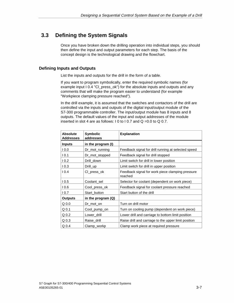
Once you have broken down the drilling operation into individual steps, you shouldthen define the input and output parameters for each step. The basis of theconcept design is the technological drawing and the flowchart.
Defining Inputs and Outputs
List the inputs and outputs for the drill in the form of a table.
If you want to program symbolically, enter the required symbolic names (forexample input I 0.4 "Cl_press_ok") for the absolute inputs and outputs and anycomments that will make the program easier to understand (for example"Workpiece clamping pressure reached").
In the drill example, it is assumed that the switches and contactors of the drill arecontrolled via the inputs and outputs of the digital input/output module of theS7-300 programmable controller. The input/output module has 8 inputs and 8outputs. The default values of the input and output addresses of the moduleinserted in slot 4 are as follows: I 0 to I 0.7 and Q =0.0 to Q 0.7.
AbsoluteAddresses
Symbolicaddresses
Explanation
Inputs in the program (I)
I 0.0 Dr_mot_running Feedback signal for drill running at selected speed
I 0.1 Dr_mot_stopped Feedback signal for drill stopped
I 0.2 Drill_down Limit switch for drill in lower position
I 0.3 Drill_up Limit switch for drill in upper position
I 0.4 Cl_press_ok Feedback signal for work piece clamping pressurereached
I 0.5 Coolant_sel Selector for coolant (dependent on work piece)
I 0.6 Cool_press_ok Feedback signal for coolant pressure reached
I 0.7 Start_button Start button of the drill
Outputs in the program (Q)
Q 0.0 Dr_mot_on Turn on drill motor
Q 0.1 Cool_pump_on Turn on cooling pump (dependent on work piece)
Q 0.2 Lower_drill Lower drill and carriage to bottom limit position
Q 0.3 Raise_drill Raise drill and carriage to the upper limit position
Q 0.4 Clamp_workp Clamp work piece at required pressure
05.04.0105.04.200105.04.2001

Designing a Sequential Control System Based on the Example of a Drill
S7 Graph for S7-300/400 Programming Sequential Control Systems3-8 A5E00105265-01
3.4 Creating the Drill Project in the SIMATIC Manager
Creating a Project
Projects for sequential control systems do not differ from other projects in STEP 7.
To create a new project in the SIMATIC Manager, follow the steps outlined below:
1. Select the menu command File > New.
2. Name the project "Drill".
Inserting an S7 Program
In this example, hardware configuration is unnecessary since the defaultaddressing of the input/output module in slot 4 is used. You can thereforeimmediately insert an S7 program in the project folder in the SIMATIC Manager.The S7 program serves as a folder for the blocks of the user program, the sourcefiles and the symbols. Follow the steps below:
1. Select the "Drill" project.
2. Select the menu command Insert > Program > S7 Program.
3. Name the S7 program "Drill Program".
The folders for source files, blocks, and symbols are created automatically whenyou insert an S7 program. An empty OB1 is also created in the Blocks folder.
05.04.0105.04.200105.04.2001
Designing a Sequential Control System Based on the Example of a Drill
S7 Graph for S7-300/400 Programming Sequential Control SystemsA5E00105265-01 3-9
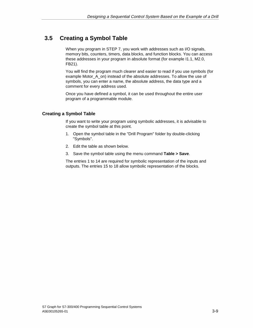
3.5 Creating a Symbol Table
When you program in STEP 7, you work with addresses such as I/O signals,memory bits, counters, timers, data blocks, and function blocks. You can accessthese addresses in your program in absolute format (for example I1.1, M2.0,FB21).
You will find the program much clearer and easier to read if you use symbols (forexample Motor_A_on) instead of the absolute addresses. To allow the use ofsymbols, you can enter a name, the absolute address, the data type and acomment for every address used.
Once you have defined a symbol, it can be used throughout the entire userprogram of a programmable module.
Creating a Symbol Table
If you want to write your program using symbolic addresses, it is advisable tocreate the symbol table at this point.
1. Open the symbol table in the "Drill Program" folder by double-clicking"Symbols".
2. Edit the table as shown below.
3. Save the symbol table using the menu command Table > Save.
The entries 1 to 14 are required for symbolic representation of the inputs andoutputs. The entries 15 to 18 allow symbolic representation of the blocks.
05.04.0105.04.200105.04.2001
Designing a Sequential Control System Based on the Example of a Drill
S7 Graph for S7-300/400 Programming Sequential Control Systems3-10 A5E00105265-01
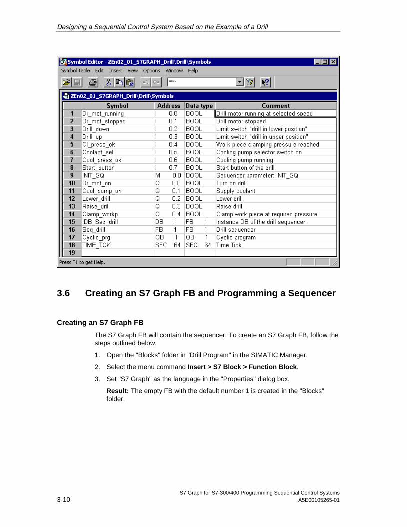
3.6 Creating an S7 Graph FB and Programming a Sequencer
Creating an S7 Graph FB
The S7 Graph FB will contain the sequencer. To create an S7 Graph FB, follow thesteps outlined below:
1. Open the "Blocks" folder in "Drill Program" in the SIMATIC Manager.
2. Select the menu command Insert > S7 Block > Function Block.
3. Set "S7 Graph" as the language in the "Properties" dialog box.
Result: The empty FB with the default number 1 is created in the "Blocks"folder.
05.04.0105.04.200105.04.2001
Designing a Sequential Control System Based on the Example of a Drill
S7 Graph for S7-300/400 Programming Sequential Control SystemsA5E00105265-01 3-11
Programming a Sequencer
After you have started the S7 Graph editor by double-clicking FB1 the systeminserts the first step (initial step) and the first transition. It is advisable to create thestructure at the "Sequencer" display level. To display conditions and actions,activate the View > Display With > Conditions and Actions menu command.
Using the mouse and the "Sequencer" toolbar at the left-hand edge of the screen,you can then position all the remaining steps and transitions, the alternativebranch and the jump from the end of the sequencer to the start of the sequencer.There are two ways of doing this and both are illustrated here.
Method 1: "Direct" Mode
1. Select transition 1 and click with the mouse until the icon
insert step + transitionuntil you arrive at step/transition 6.
2. Select step 3 and then select the icon
open alternative branch.This opens the alternative branch for supplying coolant. The branch beginswith transition 7.
3. With the mouse, select the icon
insert step + transition,and insert step 7 (S7) and transition 8 (T8).
4. Select the icon
close alternative branchand then select transition 3.
5. Now complete the sequencer structure by first selecting transition 6 and thenclicking on the icon
insert jumpand then selecting step 1.
Method 2: "Drag-and-Drop"
1. Return to the SIMATIC Manager and create function block FB2 in the "Blocks"folder as described above. Once again select "GRAPH" as the sourcelanguage.
2. Start the S7 Graph editor by double-clicking FB2 in the "Blocks" folder.
3. Select the menu command Insert > Drag-and-Drop.
05.04.0105.04.200105.04.2001

Designing a Sequential Control System Based on the Example of a Drill
S7 Graph for S7-300/400 Programming Sequential Control Systems3-12 A5E00105265-01
4. With the mouse, select the icon
insert step + transitionand then click on the last transition of the individual elements until you arrive atstep/transition 6.
5. Select the icon
open alternative branchand open the alternative branch for the coolant by clicking on step 3. Thebranch begins with transition 7.
6. With the mouse, select the icon
insert step + transition,to insert step 7 (S7) and transition 8 (T8).
7. Select the icon
close alternative branchand first select transition 8 and then transition 3.
8. Now complete the sequencer structure with
insert jumpby first selecting transition 6 and then step 1.
Note
Before you start to program step actions, close function block FB2. You onlycreated this FB to try out the second method of creating a sequencer structure.When you close the FB, answer all prompts with "No". For the rest of the exercise,you will be working in FB1.
3.7 Programming Step Actions
There are also two methods available for programming step actions andtransitions: Direct and Drag-and-Drop. The procedure described below assumesyou have selected the menu command Insert > Drag-and-Drop:
1. Select the menu command Insert > .Result: The mouse pointer then appears as shown below:
2. Insert an empty action line by clicking the action box.
3. Enter the actions.
05.04.0105.04.200105.04.2001
Designing a Sequential Control System Based on the Example of a Drill
S7 Graph for S7-300/400 Programming Sequential Control SystemsA5E00105265-01 3-13
An action consists of an instruction and an address. For the drill program, fourdifferent instructions are necessary in the steps:
• S Set output
• R Reset output
• N Non holding: As long as the step is active, the signal state of theaddress is 1.
• D Delay: The address is set to 1 after the defined time has elapsedfollowing activation of the step and is reset when the step is deactivated.
3.8 Programming Transitions
The bit logic instructions "normally open contact", "normally closed contact" and"comparator" are used for the step enabling conditions in the transitions. Toprogram transitions:
1. Set the "LAD" view and select the appropriate icons in the "LAD/FBD" toolbar
insert normally-open contact
insert normally-closed contact
insert comparator
2. Position the symbols at the appropriate points by clicking the transition lines.You can exit the insert mode at any time with the ESC key.
3. Enter the addresses. Click the placeholder "??.?" of the required text field.Then enter an absolute or symbolic address (for example I 0.7, "Start_switch").
4. If you wish, you can also enter a comment for the sequencer. In the"sequencer" view, the comment field is at the top left and can be opened byclicking it with the mouse.
05.04.0105.04.200105.04.2001

Designing a Sequential Control System Based on the Example of a Drill
S7 Graph for S7-300/400 Programming Sequential Control Systems3-14 A5E00105265-01
The following figure shows the completed sequencer.
GRAPH: Programming s7 Sequential Control Systems - Drill\...File Edit Insert PLC Debug View Options Window Help
Drill
T1
Trans1
T4Trans4
"Drill_down"
S2Cla...
T2
Trans2
S3Mo...
T3
Trans3
T7
Trans7
T8
Trans8
Drill_ready
Clamp_on
S "Clamp_workp"
Motor_on
S "Dr_mot_on"
Coolant_onS "Cool_pump_on"
Lower_drillN "Lower_drill""
S4Low...
S7Coo...
T6
"Start_button"
Clamp_press_ok"
"Drill_motor_running"
"Coolant_
sel"
"Cool_press_ok"
S1Dr...
"Drill_moto
r_running"
"Coolant_
sel"
S5Rai...
T5
Trans5
"Drill_up"
"Cl_press_ok"
T6
Trans6
"Cool_press_ok"
S6Cla...
S1
CMPTerm_M_pump_off.T
T#500MS
Raise_drillD "Raise_drill""
T#500MS
Term_M_pump_offR ""Clamp_workp"R "Dr_mot_on"R "Cool_pump_on"
"Drill_motor_stopped"
>=
When programming comparators, you can use the system information for steps asthe addresses. The addresses have the following significance:
• Step_name.T: current or last activation time of the step
• Step_name.U: current or last activation time of the step without the time of adisturbance
05.04.0105.04.200105.04.2001
Designing a Sequential Control System Based on the Example of a Drill
S7 Graph for S7-300/400 Programming Sequential Control SystemsA5E00105265-01 3-15
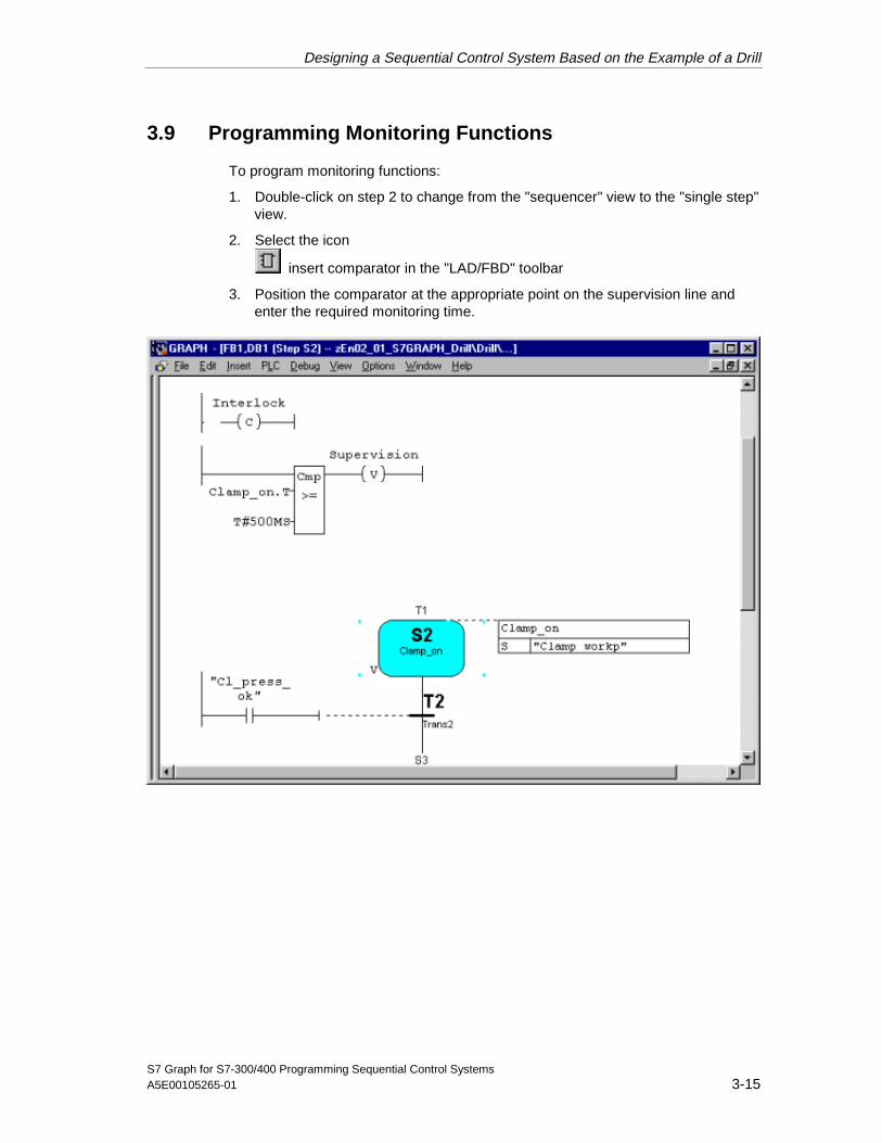
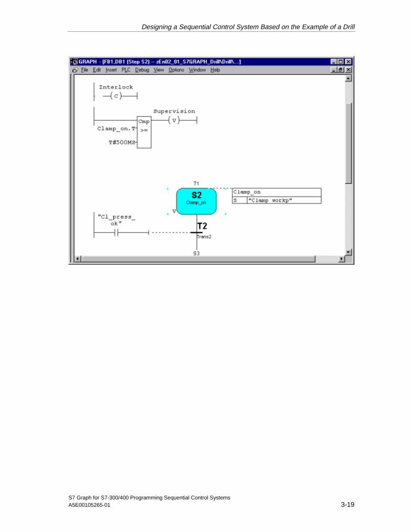
3.9 Programming Monitoring Functions
To program monitoring functions:
1. Double-click on step 2 to change from the "sequencer" view to the "single step"view.
2. Select the icon
insert comparator in the "LAD/FBD" toolbar
3. Position the comparator at the appropriate point on the supervision line andenter the required monitoring time.
05.04.0105.04.200105.04.2001

Designing a Sequential Control System Based on the Example of a Drill
S7 Graph for S7-300/400 Programming Sequential Control Systems3-16 A5E00105265-01
3.10 Specifying the Standard Function Block
Executability of the S7 Graph FB
S7 Graph has two options available for creating FBs.
• Full code:The entire code required to execute each S7 Graph FB is included in the FB. Ifyou have several S7 Graph FBs, this means a considerable increase inmemory requirements.
• Standard FC required:To reduce memory requirements, S7 Graph has the two following alternatives:You use a standard FC containing the main code sections for all FBs. This FCis copied to your project automatically when you select this option. The FBsproduced using this method are considerably smaller.
For this example, use the compilation option "Full code".
The most suitable FC depends on the performance of your CPU. Select one of thefollowing standard FCs:
FC Number Functionality
FC72 As default, you work with FC72. Remember, that your CPU must be capable of processingblocks with more than 8 Kbytes.
FC70/FC71 These two FCs are less than 8 Kbytes in size and can therefore be loaded on a smallerCPU. FC70 uses the diagnostic functionality of SFC17/18 and can only be used on CPUsthat have these functions available. If your CPU does not have these functions, you mustuse FC71 and do without diagnostic capability.
If you want to check whether or not your CPU contains these SFCs, select the menucommand PLC > Obtainable Nodes in the SIMATIC Manager or click the correspondingbutton in the toolbar. Open the "Blocks" folder in the S7 program.
FC73 This block requires less than 8 Kbytes of memory so that it can be executed on all CPUs.
Using this FC considerably reduces the memory requirements of the S7 Graph FBs. Youmust also select the option "Interface Description: Memory minimized" in the blocksettings.
The following restrictions, do, however, apply:
The blocks created do not have diagnostic capability
When you monitor the sequential control system, you will see the status display only forthe selected active element.
05.04.0105.04.200105.04.2001
Designing a Sequential Control System Based on the Example of a Drill
S7 Graph for S7-300/400 Programming Sequential Control SystemsA5E00105265-01 3-17
Setting the Executability
Select the menu command Options > Block Settings and specify that theS7 Graph FB can be executed with a standard FC in the Compile/Save tab. Enterthe FC number that matches the performance of your CPU.
The block is automatically copied to the user project if you select FC70/71, FC72 orFC73 as the block number and there is not yet an FC with this number in the targetproject. If you want to use a different number for the standard block, you must copyand renumber yourself.
3.11 Saving and Closing the Sequencer
When you save the sequencer, it is automatically compiled.
1. Select the menu command File > Save.
Result: The "Select Instance DB" dialog box is opened with the default instanceDB (DB1).
2. Accept the settings by clicking "OK".
Result: The instance data block is automatically created in the "Blocks" folder.
Note
The warning "S1 without content" in the compiler log simply means that no actionis programmed in step 1.
3. To close the sequencer, select the menu command File > Close.
05.04.0105.04.200105.04.2001
Designing a Sequential Control System Based on the Example of a Drill
S7 Graph for S7-300/400 Programming Sequential Control Systems3-18 A5E00105265-01
3.12 Including the Sequencer in the STEP 7 Program
Programming OB1
The sequential control program for the drill is called and started in organizationblock OB1. You can create OB1 in LAD, FBD, STL or SCL (here it was created inLAD). Program OB1 as shown in the following diagram. Follow the steps below:
1. Open the "Blocks" folder in the "Drill Program" S7 program in the SIMATICManager.
2. Start the LAD/STL/FBD editor by double-clicking OB1.
3. With the menu command View, select the programming language LAD.
4. Select segment 1 and insert the sequencer call using the program elementcatalog by double-clicking FB1 (Seq_drill).
5. Type in the name of the corresponding instance data block (IDB_Seq_drill)above the LAD box.
6. Select the input parameter INIT_SQ, insert a normally open element using the"LAD" toolbar and label it M0.0 ("INIT_SQ"). Using this parameter, you can setthe sequencer to the initial step (in the example step 1) in the online mode.
7. Select the menu command File > Save and close the organization block withthe menu command File > Close.
Note
All other block parameters can be ignored for the example.
05.04.0105.04.200105.04.2001
Designing a Sequential Control System Based on the Example of a Drill
S7 Graph for S7-300/400 Programming Sequential Control SystemsA5E00105265-01 3-19
05.04.0105.04.200105.04.2001

Designing a Sequential Control System Based on the Example of a Drill
S7 Graph for S7-300/400 Programming Sequential Control Systems3-20 A5E00105265-01
3.13 Downloading the Program to the CPU and Testing theSequencer
Downloading the User Program
To allow you to download the program to the CPU, you must download all theblocks (DB1, FB1, OB1, FC70/71, FC72 and/or. FC73) to the CPU of theprogrammable controller in the SIMATIC Manager. Follow the steps outlined below:
1. Open the "Drill Program" S7 program in the SIMATIC Manager and select the"Blocks" folder.
2. Select the menu command PLC > Download.
Caution
It is best to download the S7 Graph block in the STOP mode since followingdownloading of the instance DB, the sequencer is automatically set to the initialstate.
You should only download S7 Graph blocks in the RUN-P mode when thesequencer is in the initial state or in the OFF state. If you download the blocks thesequencer in a different state, for example when overwriting an old block,problems may occur in the synchronization of the sequencer with the process.
Testing the User Program
To test the user program, you require an online connection to a CPU.
3. Open the project window in the SIMATIC Manager.
4. Open the sequencer by double-clicking FB1.
5. Select the menu command Debug > Monitor.
Result: The program status is displayed (the initial step is active). Active stepsare displayed in color.
Caution
A monitoring time is programmed in step 2. If the step activation time exceeds theconfigured monitoring time (500 ms) in the supervision condition, the systemrecognizes a supervision error and the disturbed step is displayed in red. If a faultoccurs, you must first satisfy the condition for progressing to the next transition.Using the PG function Debug > Control Sequencer you can then enter anacknowledgment (see also "Control Sequencer").
This does not apply to the inching mode, since the step enabling condition mustbe satisfied and the acknowledgment received within one cycle.
05.04.0105.04.200105.04.2001
Designing a Sequential Control System Based on the Example of a Drill
S7 Graph for S7-300/400 Programming Sequential Control SystemsA5E00105265-01 3-21
3.14 Test Function: Control Sequencer
Control Sequencer is a test function with which you can test the sequencer inS7 Graph in all modes. All the settings and entries for the dialog box have thesame effect as the corresponding FB parameters.
The entries in the "Control Sequencer" dialog box can be different from the settingsyou used to compile the sequencers. The dialog box settings have priority.
"Control Sequencer" Dialog box
The "Control Sequencer" dialog box is used both as an output field that displaysthe current settings and as an input field in which you can change the currentstatus.
If you acknowledge an error, initialize the sequencer, or want to change the step inthe manual mode, call the dialog box with the menu command Debug > ControlSequencer.
Acknowledge
If the "Acknowledge errors" option is clicked, you acknowledge a pending errormessage with the "Acknowledge" button. In this way, you can acknowledge adisturbance caused, for example, by the configured monitoring time in Step 2 beingexceeded.
Note, however, that before you acknowledge the error you must make sure that thesupervision or interlock conditions that led to the error are no longer satisfied.
After an error has occurred, you can enable the next step in the sequencer bysatisfying the step enable condition because the last step enable condition in thecycle in which you acknowledge has priority over the supervision. You mustnevertheless acknowledge the error.
If the error was caused because the undisturbed activation time Step name.U hasexceeded the configured monitoring time, you can move on the sequencer byclicking the "Acknowledge" button.
This is possible because the Step name.U variable is set to "0" when youacknowledge.
Initialize
With the "Initialize" button, you can restart the sequencer completely with thedefined initial step.
05.04.0105.04.200105.04.2001
Designing a Sequential Control System Based on the Example of a Drill
S7 Graph for S7-300/400 Programming Sequential Control Systems3-22 A5E00105265-01
Setting the Mode
If you click one of the round option buttons, you switch the sequencer to theselected mode.
You can, for example, run your sequencer in the manual mode instead of theautomatic mode. In the manual mode, you can activate or deactivate any step.Follow the steps outlined below:
1. Enter the step number of the step you want to process in the "Step number"box or simply click the required step.
2. Select the action to be executed with the step:
- Activate The selected step is activated even if the preceding transition isnot satisfied.
- Deactivate The selected step is deactivated.
Note that before you activate a step you must first deactivate the currently activestep since only one step can be active at any one time in a linear sequencer. Inother words, you can only activate the required step when you have deactivatedthe currently active step.
If you have set a new mode, the original mode is indicated in bold face.
After you have controlled your sequencer in the manual mode, you can return tothe automatic mode and close the "Control Sequencer" dialog box.
3.15 Modifying the Sequencer
Often, a program does not run as required at the first attempt. This means thatchanges and modifications are required. This is also the case in our sampleprogram. The configured monitoring time in Step 2 is too short and the programhangs at this step. The following section explains how to make the requiredchanges. You must first change to the "offline" mode.
Modifying the Monitoring Time
The monitoring time configured in Step 2 is 500 ms. To give you more time forsetting the "Cl_press_ok" variable, change the monitoring time to 5 s as explainedbelow:
1. Double-click on step 2 to change from the "sequencer" view to the "single step"view.
2. Close the status by selecting the menu command Debug > Monitor or clicking
the following button: .
3. Enter the value 5 s for the monitoring time.
4. Save the sequencer with the menu command File > Save, since the sequencermust be recompiled.
05.04.0105.04.200105.04.2001

Designing a Sequential Control System Based on the Example of a Drill
S7 Graph for S7-300/400 Programming Sequential Control SystemsA5E00105265-01 3-23
Downloading the Modified Sequencer
Once you have compiled the sequencer, you must download it to the CPU. Youcan download the sequencer in the SIMATIC Manager or in the S7 Graph editor. Inthe S7 Graph editor, follow the steps outlined below:
1. With the FB open, select the menu command PLC > Download or click on the
Download button . The "Download" dialog box is opened.
2. Accept the defaults by clicking "OK".
3. Confirm the prompt to overwrite the existing blocks.
Include Instance DB
If you have not cleared the system default "Include Instance DB", S7 Graph checkswhether the instance DB has changed since it was last downloaded and whether itmust be updated. The option "Download with Instance DB" is clicked in the"Download" dialog box.
Otherwise, S7 Graph does not check the instance DB and leaves you to decidewhether or not to download the instance DB again. The option "Download withInstance DB" is not clicked in the "Download" dialog box.
Restarting the Status
To be able to monitor or control the sequencer again, restart Status by selecting
the menu command Debug > Monitor or by selecting the Monitor button.
05.04.0105.04.200105.04.2001

Designing a Sequential Control System Based on the Example of a Drill
S7 Graph for S7-300/400 Programming Sequential Control Systems3-24 A5E00105265-01
05.04.0105.04.200105.04.2001

S7 Graph for S7-300/400 Programming Sequential Control SystemsA5E00105265-01 4-1
4 Working with an S7 Graph
4.1 Starting S7 Graph
Requirements for Starting S7 Graph
• The STEP 7 standard package is installed on your PC/programming device.
• S7 Graph is installed on your PC/programming device.
• You have installed the authorization for S7 Graph.
Starting S7 Graph
There are two ways of starting S7 Graph:
• Starting in WindowsStart S7 Graph by clicking the "Start" button on the taskbar in Windows.The S7 Graph entry is under Simatic > STEP 7 > S7 Graph - ProgrammingSequential Control Systems.
• Starting in the SIMATIC managerIn the SIMATIC manager, double-click an S7 Graph FB or an S7 Graph sourcefile.S7 Graph is started and displays the selected block in the default view.
05.04.0105.04.200105.04.2001

Working with an S7 Graph
S7 Graph for S7-300/400 Programming Sequential Control Systems4-2 A5E00105265-01
4.2 The S7 Graph User Interface
Elements of the S7 Graph User Interface
These sections describe the elements of the user interface numbered in the figure.
(1) Toolbars
(2) Work area
(3) Menu bar
(4) Title bar
(5) Overview window
(6) "Details" window
(7) Status bar
05.04.0105.04.200105.04.2001

Working with an S7 Graph
S7 Graph for S7-300/400 Programming Sequential Control SystemsA5E00105265-01 4-3
Title Bar
The title bar is at the upper edge of a window. Apart from the standard Windowsbuttons, the title bars contain the following information:
• Title of the software
• Name and number of the open FB and DB
• Selected display level
• Name of the source with complete path
Working Area
The working area is a window within S7 Graph in which the sequences of anS7 Graph FB or an S7 Graph source file are displayed and can be edited.
Within the main window of S7 Graph, you can open up to 10 windows at the sametime. You can cascade or tile these windows.
Menu Bar
Just like other Windows applications, S7 Graph has a menu bar below the title barof the main window. The display of the menu commands is context-sensitive. Themenu commands are either active (black) or inactive (gray) depending on whetheror not the command can be applied to the currently selected object.
Toolbars
The toolbars contain buttons with which you can start frequently required andcurrently available menu commands.
The names of the toolbars in S7 Graph are visible when the toolbars are positionedwithin the main window.
Name Content
Standard Contains functions for handling files (opening, saving etc.) and for editing(copying, pasting etc.).
View Contains symbols for selecting various views (for example how S7 GraphFBs are displayed, display of symbolic names etc.).
Sequencer Contains buttons for editing the sequencer (for example inserting astep-transition pair).
LAD/FBD Contains buttons for inserting Ladder Logic/FBD elements (for examplecomparator).
05.04.0105.04.200105.04.2001

Working with an S7 Graph
S7 Graph for S7-300/400 Programming Sequential Control Systems4-4 A5E00105265-01
Overview Window
The overview window is displayed to the left of the working area and contains twotabs:
Variables Tab
Displays the variable declaration with the sections IN, OUT, IN_OUT, STAT andTEMP. Further program elements are also displayed: Symbols from the symboltable, preprogrammed blocks from the block folder, blocks from libraries, and stepsand transitions along with their components used in S7 Graph FBs.
In this tab, you can modify existing parameter sets, system parameters can bedeleted but cannot be edited. It is also possible to extend your own parameters.
If you want to use a parameter or a program element in the sequencer, you candrag it from the variable declaration window to the sequencer using the mouse andposition it at the required location.
Changes you have made to the parameters in the variable declaration window areautomatically updated in the sequencer so that no inconsistencies can result.
With the F1 key, detailed help is available on declaring variables in the variabledeclaration window.
For more detailed information on the declared variables and program elements,refer to the "Details" window (Variables tab). You can open this window with themenu command View > Details.
05.04.0105.04.200105.04.2001
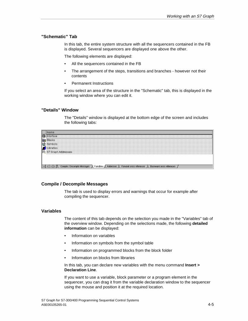
Working with an S7 Graph
S7 Graph for S7-300/400 Programming Sequential Control SystemsA5E00105265-01 4-5
"Schematic" Tab
In this tab, the entire system structure with all the sequencers contained in the FBis displayed. Several sequencers are displayed one above the other.
The following elements are displayed:
• All the sequencers contained in the FB
• The arrangement of the steps, transitions and branches - however not theircontents
• Permanent Instructions
If you select an area of the structure in the "Schematic" tab, this is displayed in theworking window where you can edit it.
"Details" Window
The "Details" window is displayed at the bottom edge of the screen and includesthe following tabs:
Compile / Decompile Messages
The tab is used to display errors and warnings that occur for example aftercompiling the sequencer.
Variables
The content of this tab depends on the selection you made in the "Variables" tab ofthe overview window. Depending on the selections made, the following detailedinformation can be displayed:
• Information on variables
• Information on symbols from the symbol table
• Information on programmed blocks from the block folder
• Information on blocks from libraries
In this tab, you can declare new variables with the menu command Insert >Declaration Line.
If you want to use a variable, block parameter or a program element in thesequencer, you can drag it from the variable declaration window to the sequencerusing the mouse and position it at the required location.
05.04.0105.04.200105.04.2001
Working with an S7 Graph
S7 Graph for S7-300/400 Programming Sequential Control Systems4-6 A5E00105265-01
Addresses
This tab contains a list of the addresses used in the block with their locations,symbols, and data types. During monitoring, the tab displays a further columnwhen "Single Step" or "Permanent Instructions" is set displaying the current statusvalue of the address during program execution.
Whether or not this is displayed depends on the setting for the working area.
Setting for the Working Area Displayed Addresses
Sequencer Addresses in the program
Single step display Addresses of the step and corresponding transition
Permanent Instructions Addresses used in the permanent instruction
Forward Cross References
Show the use of addresses in the memory areas Q, M, T, and C within the userprogram.
The forward cross-references tab displays all the addresses supplied with values inthe current block and evaluated at other points in the program.
Backward Cross References
The backward cross-references tab displays all the addresses supplied with thevalues at other locations in the program and evaluated in the current block.
Status Bar
The status bar is at the bottom edge of the main window of S7 Graph. By selectingthe menu command View > Status Bar, you can display or hide the status bar.
In the left half of the status bar you will see brief information about the selectedmenu command. The right-hand side of the status bar contains the followinginformation:The following symbols identify the various connection and operating states:
Symbol Display Description With
offline You are editing a block saved on theprogramming device/PC.
S7-300andS7-400
Disconnected The connection to the PLC has beendisconnected.
S7-300andS7-400
CONNECTED You are editing a block that is located on a PLC(SIMATIC S7).
S7-300
RUN Operating mode of the module S7-400
STOP Operating mode of the module S7-400
FRCE There is a force job. S7-400
05.04.0105.04.200105.04.2001

Working with an S7 Graph
S7 Graph for S7-300/400 Programming Sequential Control SystemsA5E00105265-01 4-7
The following displays are shown on a colored background in the status bar:
Display Color
FRCE Yellow
STOP Red
HALT Yellow
Disconnected White
RUN in "Program status on" Green bar
Abs/Sym
The address priority set in the properties of the block folder.
The address priority specifies whether the absolute addresses or the symbols arevalid if changes are made in the symbol table.
Ins/OVR/Rd
• Insert/OverwriteEditing mode for input
• ReadThe block is read-only.
Chg/Chg. Interface
Indicates that the block has been changed and whether the change involves theinterface.
05.04.0105.04.200105.04.2001

Working with an S7 Graph
S7 Graph for S7-300/400 Programming Sequential Control Systems4-8 A5E00105265-01
4.3 Settings for the Work Area
To allow you to customize the work area and appearance of the user interface,S7 Graph has various display modes and settings. Some of the settings are savedalong with the block you are editing.
S7 Graph supports you with different display levels that you can select with theView menu:
• Sequencer
• Single Step Display
• Permanent Instructions
Sequencer
At the "Sequencer" display level, one of the sequencers contained in the FB. Ifseveral sequencers exist, you can change from one to the other by selecting the"Graphic" tab in the overview window.
This display level is ideal for configuring the sequencers. At this level, you canspecify the structure of the sequencers and select the numbers, names andcomments for steps and transitions.
With the menu command View > Display With > Conditions and Actions, youcan display the contents of the configured steps and transitions.
The following elements are displayed:
• The block comment
• The arrangement of the steps, transitions, and branches
• As an option, you can display the contents of the steps and transitions
• Depending on the zoom factor, step and transition names are displayed
Single Step Display
At the single step level, only one step-transition pair is displayed. All the detailedinformation can be programmed at this display level, as follows:
• Action: Actions executed within the step
• Supervision: Conditions for monitoring the displayed step
• Interlock: Conditions for interlocking the displayed step
05.04.0105.04.200105.04.2001
Working with an S7 Graph
S7 Graph for S7-300/400 Programming Sequential Control SystemsA5E00105265-01 4-9
• Transition: Conditions for enabling the step following the currently displayedstep
• step comments
• Numbers and names of the displayed step-transition pair
• The extended name
• List of the symbolic addresses
Note
To display a different step without changing the view, you can use the menucommand Edit > Go To.
To change to the next or previous step, use the cursor keys.
Permanent Instructions
At the permanent instructions display level, you can program the following:
• Permanent instructions before the sequencer
• Permanent instructions after the sequencer
Setting a Display Level
To set a display level:
1. Open the View menu.
2. Select the display level suitable for the current task:
- Sequencer for structuring the sequencer
- Single step to program individual steps and transitions.
- Permanent instructions for programming permanent conditions andpermanent block calls
Default Setting of a Display Level
An S7 Graph FB is always opened at the default display level. You select thedefault with the menu command Options > Application Settings in the "General"tab.
Under "New Window View" select the display level at which the S7 Graph FB willbe opened.
05.04.0105.04.200105.04.2001

Working with an S7 Graph
S7 Graph for S7-300/400 Programming Sequential Control Systems4-10 A5E00105265-01
4.4 Customizing a Display Level, Colors and Fonts
Customizing a Display Level
You can adapt the selected display level to suit your purposes. S7 Graph providesthe following options:
• Zoom in and zoom out
• Zoom factor for the current display
• Lasso functions for zooming
• Buttons for handling windows
• Displaying and hiding selected areas
• Setting a default display for certain areas
Zoom In and Zoom Out
Select the menu commands View > Zoom In or Zoom Out to change the size ofthe display.
Specifying a Zoom Factor for the Current Display
You can adapt the size of the current display to suit its contents by selecting themenu command View > Zoom Factor.
If you select a zoom factor that would make text too small to be legible, the stepand transition names are no longer displayed and only the numbers of steps andtransitions are visible. You can, nevertheless, display step and transition names bypositioning the mouse pointer on the step or transition.
If you want to avoid this, you can specify minimum zoom factors for the variousviews so that the display size never becomes illegible.
You can also revert to the previous zoom factor at any time.
Lasso Functions for Zooming
If you want to increase the size of a specific area, you can also use the lassofunction. Select the menu command View > Enlarge Active Area. Then drag arectangle round the area you want to zoom using the mouse. Now only theselected area is displayed in the S7 Graph work area.
05.04.0105.04.200105.04.2001

Working with an S7 Graph
S7 Graph for S7-300/400 Programming Sequential Control SystemsA5E00105265-01 4-11
Buttons for Handling Windows
S7 Graph provides you with a button for displaying and hiding the "Details" and"Overview" windows. This allows you to set up the work area to suit yourrequirements.
Displaying and Hiding Areas
Apart from displaying individual steps and transitions, S7 Graph provides furtheroptions in the work area. Select the required menu commands from the Viewmenu:
• To display a comment field: View > Display With > Comments
• To display addresses in symbolic representation: View > Display With >Symbols
• To display conditions and actions: View > Display With > Conditions andActions
• To display a list box for selecting addresses when editing actions: View >Display With > Symbol List
Defaults for the Display of Additional Elements
Additional elements can also be displayed as part of the default setting when ablock is opened. You select the default with the menu command Options >Application Settings in the "General" tab. Select the displayed options to makethe default setting:
• To display a block comment or a step comment: "Display With: Comments".
• To display addresses in symbolic representation: "Display With: Symbols".
• You can display conditions and actions with View > Display With >Conditions and Actions.
Customizing Colors and Fonts
S7 Graph also allows you to customize the appearance of individual elements.These include the settings for color, font, lines, and Ladder Logic/FBD addresses.
Modifying the Settings
You can make all the required settings in the "Editor" tab. You can display this tabwith the menu command Options > Application Settings. When you close theeditor (when you quit the customize functions) any modifications you have madeare saved.
05.04.0105.04.200105.04.2001

Working with an S7 Graph
S7 Graph for S7-300/400 Programming Sequential Control Systems4-12 A5E00105265-01
Color
You can change the color of the following elements:
Element Create Mode Monitor Mode
Selected element Selected element
Step active/transition valid Elements
Step not active Inactive step
Error Operator input error Disturbed step
LAD/FBD satisfied Satisfied conditions intransition, supervision,interlock and permanentinstructions
LAD/FBD not satisfied Non-satisfied conditions intransitions, supervision,interlock, and permanentinstructions
LAD/FBD not processed Non-executed transitions,supervision conditions orinterlocks
Synchronization point Synchronization points
Font
You can change the font for the following elements
Area
Step/transition number Numbers of the steps/transitions
Step/transition name Name of the steps/transitions
LAD/FBD LAD/FBD addresses
The extended name Titles of the action tables
Actions Contents of the action tables
Comments Contents of the comment fields
Lines
You can change the line style (thickness) for the following types of line:
Line Style
Normal line The entry applies to all lines of the sequencers
Sensitive line Line to which the currently selected Graph element can beappended.
05.04.0105.04.200105.04.2001

Working with an S7 Graph
S7 Graph for S7-300/400 Programming Sequential Control SystemsA5E00105265-01 4-13
Ladder Logic Addresses and Action Lines
You can decide the maximum number of characters permitted for a LAD/FBDaddress or an action line. For the view in the program, you can limit the address toone line.
Tip: If the LAD/FBD address or the action line is not displayed completely in aparticular view, you can display the complete name as a tooltip by positioning themouse pointer on the relevant address or action.
You can also specify whether the LAD/FBD address is right-aligned and the actionsleft-aligned.
4.5 Tools for Editing the Sequencer
4.5.1 Display and Position of the Toolbars
Displaying and Hiding Toolbars
Select the menu command View > Toolbars. In the dialog box that is displayed,you can select the toolbars you want to be displayed.
Positioning the Toolbars
Toolbars can be positioned anywhere within the main window of S7 Graph. Youcan drag and drop them as required.
1. Click the gray area of the toolbar on which the buttons are arranged and holddown the mouse button.
2. Drag the toolbar with the mouse to the required position on the screen.
Display of the Buttons in Toolbars
The display of the buttons in the toolbars is context-sensitive. This means thefollowing:
• Buttons that can be clicked are displayed in black.
• Buttons that cannot be clicked are displayed in gray.
05.04.0105.04.200105.04.2001

Working with an S7 Graph
S7 Graph for S7-300/400 Programming Sequential Control Systems4-14 A5E00105265-01
4.5.2 Editing the Sequencer with the Toolbars
The way in which you edit a sequencer with the buttons of the toolbar is decided bythe menu command Insert > Drag-and-Drop or Insert > Direct.
• In the Drag-and-Drop editing mode, you drag an element button (symbol) fromthe toolbar to the required position.
• In the Direct mode, you position a symbol at the selected point.
"Drag and Drop" editing mode
When you are working in the "Drag and Drop" editing mode, you add elements asfollows:
1. Click an element button in the toolbar with the mouse pointer or select anelement from the Insert menu.
Result: The mouse pointer takes on the appropriate shape.
2. Now click the position at which you want to insert the element. If the mousepointer takes the shape of a "prohibited sign" (a circle with a diagonal bar), thisindicates that the element cannot be inserted at the selected point. Each clickinserts a further element.
3. After you have inserted all the required elements, click the button in the toolbaror the menu command from the Insert menu again to complete the action.
"Direct" Editing Mode
If you are in the "Direct" editing mode, you insert elements as follows:
1. Select the element after which you want to insert a new element.
2. Click an element button in the toolbar with the mouse pointer or select anelement from the Insert menu.
3. To add further elements of the same type at the same position, click the buttonor the menu command from the Insert menu again.
05.04.0105.04.200105.04.2001
Working with an S7 Graph
S7 Graph for S7-300/400 Programming Sequential Control SystemsA5E00105265-01 4-15
4.5.3 Navigating in the Sequencer
To allow you to navigate in the sequencer, you can use not only the keys of thecursor pad but also the functions in the Edit > Go To menu. These functions makeit easier to navigate through large sequencers and when debugging.
Displaying a Specific Step or Transition
With the menu command Edit > Go To > Step / Transition, you can jump to aspecific step-transition pair. You can specify either the number or the name.
Searching for Occurrences of an Address
This function displays a table showing all points at which the selected address isused in the entire S7 program. The table contains information about the following:
• Block: Indicates the block in which the address is used
• Type: Indicates whether the address is read (R) and/or written (W).
• Language/details: Block information
Displaying the Next or Previous Error
If errors are displayed in the message window after compilation, you can use themenu commands Edit > Go To > Next Error and Edit > Go To > Previous Errorto jump to the error. S7 Graph then jumps to the location of the error in thesequencer and displays the error message in the status bar.
05.04.0105.04.200105.04.2001

Working with an S7 Graph
S7 Graph for S7-300/400 Programming Sequential Control Systems4-16 A5E00105265-01
05.04.0105.04.200105.04.2001
S7 Graph for S7-300/400 Programming Sequential Control SystemsA5E00105265-01 5-1
5 Creating a Project
This chapter explains how you create and open your project. The chapter alsoexplains criteria with which you can decide whether to work with an S7 Graph FBor S7 Graph source files.
Steps in Creating a Project
All the information about a sequential control system is contained in a STEP 7project.
Create the project in the SIMATIC Manager and insert your S7 program
Open the block to program the sequencer(s)
Create an S7 Graph source file Create an S7 Graph FB
5.1 Creating the Project in the SIMATIC Manager
Before you can create your sequencers with S7 Graph, you must first create aproject and then an S7 program within the project. All the blocks for the sequentialcontrol system are saved in this folder.
Creating a New Project
You create a new project in the SIMATIC Manager using the menu command File> New. As an alternative, from Version 4 onwards, STEP 7 has a wizard that helpsyou to create an entire project structure. Select the method you prefer to create aproject.
Inserting an S7 Program in the Project
In the SIMATIC Manager, you create an S7 program with the menu commandInsert > Program > S7 Program. The system then automatically creates thefolders for source files, blocks and the symbol table. An empty OB1 is created inthe Blocks folder.
05.04.0105.04.200105.04.2001
Creating a Project
S7 Graph for S7-300/400 Programming Sequential Control Systems5-2 A5E00105265-01
5.2 S7 Graph FB or S7 Graph Source File?
Before you start to create sequencers, you must first decide the type of block inwhich you want to program. You can create sequencers either in an S7 Graph FBor in an S7 Graph source file.
Deciding Between an S7 Graph FB and an S7 Graph Source File
When you save an FB, S7 Graph implicitly compiles the block, in other words thesequencer you have created is checked for syntax errors. Only error-free S7 GraphFBs can be saved and transferred to the CPU. It is not possible to close an FB thatcontains errors.
If you are unable to debug the program immediately, you can also save theS7 Graph FB as a source file or you can first create an S7 Graph FB source fileinstead of an S7 Graph FB. In contrast to the S7 Graph FB, you can save anS7 Graph source file containing errors at any time.
Note
If you find that you cannot program a sequencer in one session, first save the dataas an S7 Graph source file or create an S7 Graph source file in the first place.
05.04.0105.04.200105.04.2001

Creating a Project
S7 Graph for S7-300/400 Programming Sequential Control SystemsA5E00105265-01 5-3
5.3 S7 Graph FB
You can create an S7 Graph FB both in the SIMATIC Manager or directly inS7 Graph, as follows:
• In S7 Graph, you create a new function block with the File > New menucommand. This is then created in the S7 Graph language.
• In the SIMATIC Manager, you create a new function block with the Insert >S7 Block > Function Block menu command. In this case set the language toS7 Graph.
Rules for Creating the S7 Graph FB
The S7 Graph FB is saved in the Blocks folder. The following rules apply:
• You can program the sequencer with absolute and symbolic addresses.
• The FB is displayed depending on its location:
- offline: The FB is displayed from the hard disk of the programming devicealong with the symbols and comments.
- online: The FB from the CPU is displayed along with comments andsymbols from the hard disk of the programming device (assuming thatthese exist offline).
- online without existing project structure: The FB from the CPU is displayed(view "Accessible Nodes" in the "Open" dialog box) like a STEP 7 FB, inother words without symbols and comments.
5.4 S7 Graph Source File
You can create source files both in the SIMATIC Manager and in S7 Graph andusing other editors and then import the files later into an S7 project. Make sure thatyou know the syntax required as described in the online help.
Rules for Creating and Calling the S7 Graph Source File
The S7 Graph source file is saved in the source files folder. The following rulesapply:
1. Empty S7 Graph source files can also be created in the SIMATIC Manager orimported into the open project.
2. In S7 Graph, an S7 Graph source file can also be created from an openS7 Graph FB.
3. Existing S7 Graph source files can be opened both in the SIMATIC Managerand in the S7 Graph editor. They are then displayed in the S7 Graph editor andcan be edited.
4. Source files can only be edited offline in a project.
05.04.0105.04.200105.04.2001

Creating a Project
S7 Graph for S7-300/400 Programming Sequential Control Systems5-4 A5E00105265-01
5.5 Opening an S7 Graph FB or an S7 Graph Source File
You can open an S7 Graph FB or an S7 Graph source file either in the SIMATICManager or in S7 Graph.
Note
If you create a new FB in S7 Graph, this is opened directly.
Opening in the SIMATIC Manager
In the SIMATIC Manager, follow the steps outlined below:
• Select the required object in the blocks or source files folder and double-clickto open it.
Opening in the S7 Graph Editor
In the S7 Graph editor, follow the steps outlined below:
1. Select the menu command File > Open or click the corresponding button.
2. In the dialog box that then appears, select the block or source file you want toopen. Decide whether you want to open a block on the programming device(offline) or directly on the CPU (online).
05.04.0105.04.200105.04.2001

S7 Graph for S7-300/400 Programming Sequential Control SystemsA5E00105265-01 6-1
6 Programming the Structure of a Sequencer
The section below explains the rules and elements for creating a sequencer.
OB/FB/FC DB i
T2
T1
S2
S1
Comment for ...
FB i
CALL FBi,DbiSQ_INIT:=
(1)
(2)
(3)
(4)
(5)
The heart of a sequential control system is made up of the S7 Graph FBs (1).These contain the following:
• The program for step by step execution of the controller in sequencers (4).
• Permanent instructions (3)(5) that are valid for all sequencers of the FB (andare displayed in a separate window)
• A block comment (2) with which you can describe the entire block.
How to Work with S7 Graph FBs
The order in which you perform the steps below is relatively unimportant. The ordershown is simply a suggestion.
Step Task
1 Specify the structure of the sequencer with the S7 Graph elements
2 Program the permanent instructions (optional)
3 Add a comment about the S7 Graph FB in the field for the block comment (optional)
4 Edit the steps and transitions created in point 1 individually
05.04.0105.04.200105.04.2001
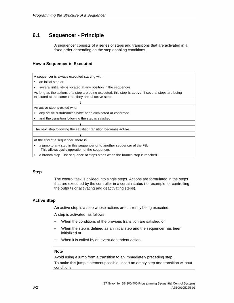
Programming the Structure of a Sequencer
S7 Graph for S7-300/400 Programming Sequential Control Systems6-2 A5E00105265-01
6.1 Sequencer - Principle
A sequencer consists of a series of steps and transitions that are activated in afixed order depending on the step enabling conditions.
How a Sequencer is Executed
A sequencer is always executed starting with
• an initial step or
• several initial steps located at any position in the sequencer
As long as the actions of a step are being executed, this step is active. If several steps are beingexecuted at the same time, they are all active steps.
An active step is exited when
• any active disturbances have been eliminated or confirmed
• and the transition following the step is satisfied.
The next step following the satisfied transition becomes active.
At the end of a sequencer, there is
• a jump to any step in this sequencer or to another sequencer of the FB.This allows cyclic operation of the sequencer.
• a branch stop. The sequence of steps stops when the branch stop is reached.
Step
The control task is divided into single steps. Actions are formulated in the stepsthat are executed by the controller in a certain status (for example for controllingthe outputs or activating and deactivating steps).
Active Step
An active step is a step whose actions are currently being executed.
A step is activated, as follows:
• When the conditions of the previous transition are satisfied or
• When the step is defined as an initial step and the sequencer has beeninitialized or
• When it is called by an event-dependent action.
Note
Avoid using a jump from a transition to an immediately preceding step.
To make this jump statement possible, insert an empty step and transition withoutconditions.
05.04.0105.04.200105.04.2001
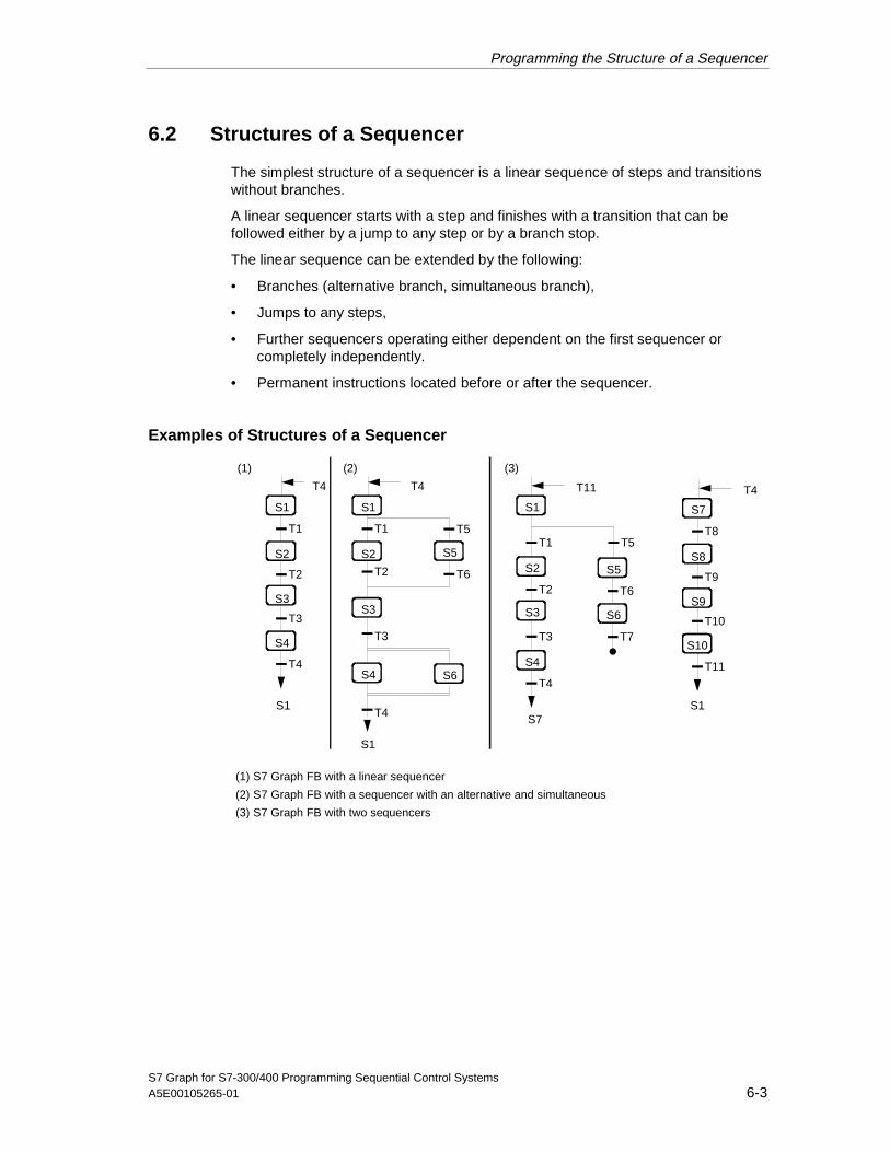
Programming the Structure of a Sequencer
S7 Graph for S7-300/400 Programming Sequential Control SystemsA5E00105265-01 6-3
6.2 Structures of a Sequencer
The simplest structure of a sequencer is a linear sequence of steps and transitionswithout branches.
A linear sequencer starts with a step and finishes with a transition that can befollowed either by a jump to any step or by a branch stop.
The linear sequence can be extended by the following:
• Branches (alternative branch, simultaneous branch),
• Jumps to any steps,
• Further sequencers operating either dependent on the first sequencer orcompletely independently.
• Permanent instructions located before or after the sequencer.
Examples of Structures of a Sequencer
T2
T1
T4
T3
T6T2
T1
T3
T5
T6T2
T1
T4
T3
S1 S1 S1
S2 S2S2
S3
S4
S3
S5
S3
S4
S5
S6
S1
S7
T4 T11
S4 S6
T4
T9
T8
T11
T10
S7
S8
S9
S10
S1
T4
T7
T5
(1) S7 Graph FB with a linear sequencer
(2) S7 Graph FB with a sequencer with an alternative and simultaneous
(3) S7 Graph FB with two sequencers
T4
(1) (2) (3)
S1
05.04.0105.04.200105.04.2001

Programming the Structure of a Sequencer
S7 Graph for S7-300/400 Programming Sequential Control Systems6-4 A5E00105265-01
6.3 Rules for the Structure of a Sequencer
The structure of the sequencer must satisfy the following rules:
• An S7 Graph FB can contain up to 250 steps or 250 transitions. Steps andtransitions can only be inserted as pairs.
• When the S7 Graph FB is called, the sequencers are started
- at the first step of the sequencer or
- at an initial step.
• A sequencer can contain a maximum of 256 branches with
- up to 125 paths in alternative branches or
- up to 249 simultaneous sub-branches.
In practical terms, and depending on the CPU, only 20 to 40 paths areadvisable otherwise extremely long run times will result.
• A branch can only join a path of a branch to the left of the path being closed.
• Jumps can be added following a transition at the end of a path in a branch.These lead to a junction before a step in the same or in a different sequencerin the current FB.
• A branch stop can be added after a transition at the end of a path in a branchand deactivates the execution of the path.
• Permanent instructions can be defined before or after the sequencer in thereserved field. These are called once per cycle.
05.04.0105.04.200105.04.2001

Programming the Structure of a Sequencer
S7 Graph for S7-300/400 Programming Sequential Control SystemsA5E00105265-01 6-5
6.4 Elements of a Sequencer
The following list shows the elements that can make up a sequencer and thecorresponding element buttons in the "Sequencer" toolbar with which you cancreate these elements:
Step + Transition
Jump
Open Alternative Branch
Close Alternative Branch
Open Simultaneous Branch
Close Simultaneous Branch
Branch Stop
Insert Sequencer
You program the structure of the sequencer at the "Sequencer" display level.
6.5 Step-Transition Pair and Initial Step
Step-Transition Pair
As default, the S7 Graph FB already contains one step-transition pair to which youcan append further step-transition pairs.
Steps and transitions can only be inserted in pairs in a sequencer.
When you insert steps and transitions, they are automatically assigned a number.To ensure a better overview, you can renumber steps and transitions within acertain range later so that the numbering is consecutive.
Initial Step
The initial step is the step in a sequencer that becomes active without previouslyquerying conditions when an S7 Graph FB is first called. The initial step is notnecessarily the first step in a sequencer.
When a sequencer is run through cyclically, this step (just like every other step)only becomes active when the conditions of the previous transition are satisfied.
The sequencer is initialized by the FB parameter INIT_SQ = 1. In other words thesequencer starts with the initial step.
05.04.0105.04.200105.04.2001

Programming the Structure of a Sequencer
S7 Graph for S7-300/400 Programming Sequential Control Systems6-6 A5E00105265-01
6.6 Jump
A jump is the change from a transition to any step within the sequencer or withinanother sequencer in the same FB.
A jump always follows a transition and closes the sequencer or the path of thebranch at this point.
In contrast to a branch stop, the jump has the effect of repeating the execution ofthe sequencer or parts of it.
The jump (1) and the jump destination (2) are displayed graphically as an arrow butthe connection itself is not visible.
T5T2
T1
T4
T3
T7
T8
T11
T9
T12
T13
T14
T10
1
2
S1
S2
S3
S4
S1
S5
S6
S7
S8
S9
T8T4T12
S9
S11
S12
S13
S14
S1
Caution
A jump to a simultaneous branch should be avoided.
05.04.0105.04.200105.04.2001

Programming the Structure of a Sequencer
S7 Graph for S7-300/400 Programming Sequential Control SystemsA5E00105265-01 6-7
6.7 Alternative Branch
An alternative branch consists of two or more parallel sub-branches (a maximum of125). Each path in an alternative branch begins with a transition. Only the branchpath whose transition switches first is executed. An alternative branch thereforecorresponds to an OR operation in which only one path can be active.
Each path in an alternative branch ends with a transition and can be closed by abranch stop or a jump.
Tn
TmT2
T1
T4
T3
T6
Ty
Tx
T7
Jump
T5
1 2 3
➀: Alternative sub-branch 1
➁: Alternative sub-branch 2
➂: Alternative sub-branch 3 with a further alternative branch
Tz
Tx+1
Jump
S1
S2
S3
S4
S5
Sm
Sn
Sx
SySz
T5
Tz
Priorities in Alternative Branches
If several transitions are satisfied at the same time at the start of various branches,the transition located furthest left has the highest priority.
05.04.0105.04.200105.04.2001

Programming the Structure of a Sequencer
S7 Graph for S7-300/400 Programming Sequential Control Systems6-8 A5E00105265-01
6.8 Simultaneous Branch
A simultaneous branch consists of more than one parallel path (a maximum of 249)each of which starts with a step. The path are executed simultaneously. Asimultaneous branch corresponds to an AND branch.
The transition before the simultaneous branch (in the figure T1 and T7) activatesthe first steps of the individual simultaneous branch paths.
Every path in a simultaneous branch ends with a step and is completed by asuccessor transition.
If more than one simultaneous branch path joins to a transition, this transition onlyenables the next step when all active simultaneous branch paths have beenexecuted.
1 2 3
➀: Simultaneous sub-branch 1➁: Simultaneous sub-branch 2➂: Simultaneous sub-branch 3 with afurther simultaneous branch
TmT2
T4
T5
T1
T3
T7
Tx
S1
S2
S3
S4
S5
S6
Sm
S7
Sx Sz
T5
Sy
05.04.0105.04.200105.04.2001

Programming the Structure of a Sequencer
S7 Graph for S7-300/400 Programming Sequential Control SystemsA5E00105265-01 6-9
6.9 Branch Stop
A branch stop at the end of a linear sequencer (1) or at the end of a path of analternative branch (2) terminates the sequencer. The sequencer is not executedcyclically.
A branch stop at the end of a branch path of a simultaneous branch (3) terminatesonly this branch path. The execution of the other paths in the simultaneous branchcontinues.
A branch stop always follows a transition.
T4T2
T1
T3
T2
T1
T3
T5
T6
T4
T2
T1
T3 T5
1 2 3
S1
S2
S3
S4
S5
T3
S1
S2
S3
S1
S2
S3
S1 S1
S4
S5
T3
Caution
If all the paths of a sequencer are completed with a branch stop, the sequencercan only be restarted by the parameter INIT_SQ.
6.10 New Sequencer
An S7 Graph FB can consist of several sequencers.
Each sequencer can
1. be executed independent of the other sequencers and therefore at the sametime.
2. be used with a jump to continue it or connect it as the branch of anothersequencer. This allows you to represent technically complicated functions inone block providing you with a clearer structure for the program.
In every sequencer, an initial step can identify the first active step.
05.04.0105.04.200105.04.2001

Programming the Structure of a Sequencer
S7 Graph for S7-300/400 Programming Sequential Control Systems6-10 A5E00105265-01
6.11 Permanent Instructions
Permanent instructions are conditions (1) and block calls (2) located before or afterthe sequencer. These are executed once per scan cycle regardless of the state ofthe sequencer.
You can program any number of permanent instructions in an S7 Graph FB. Eachpermanent instruction is assigned a number.
You program permanent conditions in the "permanent instructions" view.
E2.3
E2.5
M2.0E0.0
CALL
1
2
(1)
(2)
Permanent Condition
Conditions that must be satisfied at more than one point in the sequencers can beprogrammed once centrally as permanent conditions. You can use the LadderLogic elements: normally-open contact, normally-closed contact, and comparatoror the FBD elements AND box, OR box, and comparator. A maximum of 32Ladder Logic/FBD elements can be programmed per permanent condition.
The result of combining the conditions is stored in a ladder coil or in an FBDassignment with which the functions set and reset are available. The address used(for example a memory bit) can be queried in a transition, interlock, andsupervision.
05.04.0105.04.200105.04.2001
Programming the Structure of a Sequencer
S7 Graph for S7-300/400 Programming Sequential Control SystemsA5E00105265-01 6-11
Permanent Block Call
Blocks that were created in a programming language other than S7 Graph can becalled using permanent block calls in an S7 Graph FB or action. After the calledblock has been executed, the execution of the S7 Graph FB is continued.
When using a block call, note the following points:
• You can call the following blocks:
- Functions (FC) and function blocks (FB) programmed in STL, LAD, FBD orSCL and
- System functions (SFC) and system function blocks (SFB).
• Function blocks and system function blocks must be assigned an instance DBwhen they are called.
• The blocks must already exist in the "Blocks" folder of the S7 program beforethey are called.
• The names of the blocks can be specified in absolute form (for example FC1)or, if they are declared in the symbol table, symbolically (for example Motor 1).·
• When the blocks are called, you must supply the formal parameters of thecalled block with actual values.
6.12 Block Comment
Every S7 Graph FB can include a block comment. The block comment can be amaximum of 2048 characters long. It has no influence on the execution of theprogram.
Block comments are displayed only in the "Sequencer" view.
Entering the Block Comment
You can enter a block comment when the menu command View > Display with >Comment is selected (check mark).
1. Select the "Sequencer" display level.
2. Enter the block comment directly in the text box located above the sequencer.
05.04.0105.04.200105.04.2001

Programming the Structure of a Sequencer
S7 Graph for S7-300/400 Programming Sequential Control Systems6-12 A5E00105265-01
05.04.0105.04.200105.04.2001
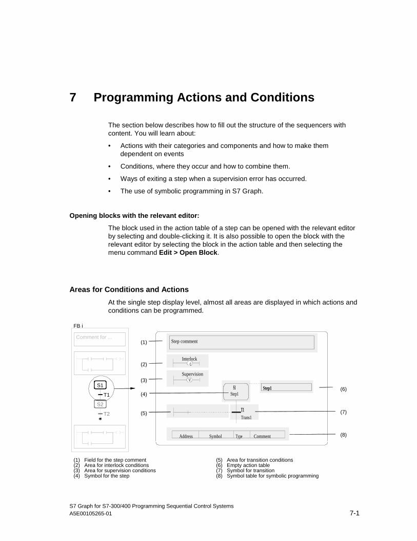
S7 Graph for S7-300/400 Programming Sequential Control SystemsA5E00105265-01 7-1
7 Programming Actions and Conditions
The section below describes how to fill out the structure of the sequencers withcontent. You will learn about:
• Actions with their categories and components and how to make themdependent on events
• Conditions, where they occur and how to combine them.
• Ways of exiting a step when a supervision error has occurred.
• The use of symbolic programming in S7 Graph.
Opening blocks with the relevant editor:
The block used in the action table of a step can be opened with the relevant editorby selecting and double-clicking it. It is also possible to open the block with therelevant editor by selecting the block in the action table and then selecting themenu command Edit > Open Block.
Areas for Conditions and Actions
At the single step display level, almost all areas are displayed in which actions andconditions can be programmed.
T2
T1
S2
S1
Comment for ...
FB i
Interlock
Supervision
S1Step1
Step1
Step comment
V
C
T1Trans1
Address Symbol Type Comment
(1)
(6)
(7)
(8)
(2)
(3)
(4)
(5)
(1) Field for the step comment(2) Area for interlock conditions(3) Area for supervision conditions(4) Symbol for the step
(5) Area for transition conditions(6) Empty action table(7) Symbol for transition(8) Symbol table for symbolic programming
05.04.0105.04.200105.04.2001

Programming Actions and Conditions
S7 Graph for S7-300/400 Programming Sequential Control Systems7-2 A5E00105265-01
Steps for Editing a Step/Transition Pair
Once you have programmed the structure of the sequencers in the S7 Graph FB,you can start to program the individual steps and transitions.
The order in which you work is of little importance. The order of the steps as shownbelow is simply a suggestion.
Step Task
1 Programming the actions in the action table
2 Programming the conditions in transitions, interlocks, supervisions and thepermanent conditions
3 Editing the numbers and names of steps and transitions or entering a stepcomment
4 Editing the section of the STEP 7 symbol table for this step
05.04.0105.04.200105.04.2001
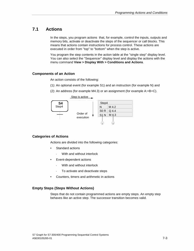
Programming Actions and Conditions
S7 Graph for S7-300/400 Programming Sequential Control SystemsA5E00105265-01 7-3
7.1 Actions
In the steps, you program actions that, for example, control the inputs, outputs andmemory bits, activate or deactivate the steps of the sequencer or call blocks. Thismeans that actions contain instructions for process control. These actions areexecuted in order from "top" to "bottom" when the step is active.
You program the step contents in the action table at the "single step" display level.You can also select the "Sequencer" display level and display the actions with themenu command View > Display With > Conditions and Actions.
Components of an Action
An action consists of the following:
(1): An optional event (for example S1) and an instruction (for example N) and
(2): An address (for example M4.3) or an assignment (for example A:=B+C).
N
S1 N
M 4.2
M 4.3
S4
S0 R Q 4.4
Step is active
Order ofexecution
Step4Step4
1 2
Categories of Actions
Actions are divided into the following categories:
• Standard actions
- With and without interlock
• Event-dependent actions
- With and without interlock
- To activate and deactivate steps
• Counters, timers and arithmetic in actions
Empty Steps (Steps Without Actions)
Steps that do not contain programmed actions are empty steps. An empty stepbehaves like an active step. The successor transition becomes valid.
05.04.0105.04.200105.04.2001

Programming Actions and Conditions
S7 Graph for S7-300/400 Programming Sequential Control Systems7-4 A5E00105265-01
7.2 Standard Actions
Standard Actions with and without Interlock
All standard actions can be combined with an interlock. The actions are onlyexecuted when the conditions of the interlock are fulfilled (letter C added).
Standard actions without an interlock are executed as long as the step is active.
Instruction AddressIdentifier
AddressLocation
Meaning:
N[C] Q,I,M,D m.n As long as the step is active [and interlocksatisfied], theaddress is set to 1.
S[C] Q,I,M,D m.n Set: As soon as the step is active [and theinterlock is satisfied],the address is set to 1 and then remains set to 1(latching)
R[C] Q,I,M,D m.n Reset: As soon as the step is active [and theinterlock issatisfied], the address is set to 0 and remains at 0(latching).
D[C] Q,I,M,D m.n On (Delay): n seconds after the step is activated,the addresshas signal 1 [if the interlock is satisfied] while thestep is active.This does not apply if the step is active for a timeshorter than nseconds (non-latching).
T#<const> Time constant
L[C] Q,I,M,D m.n Limited pulse: If the step is active [and theinterlock is satisfied],the address is set to 1 for n seconds (nonlatching).
T#<const> Time constant
CALL[C] FB, FC,SFB,SFC
Blocknumber
Block call: As long as the step is active [and theinterlock issatisfied], the specified block is called.
[ ] = optional addition to the interlock; m = byte address; n = bit address; addressrange: 0.0 to 65535.7
Address D: DBi.DBXm.n = data block number i; DBXm.n = bit in the DB;
SFB/FB = System function block/ function block; SFC/FC = Systemfunction/function
For CALL[C] FB/SFB, an instance DB is required.
Note
You can open the called block or its instance DB using the Open Block functionor by right-clicking or double-clicking on the block.
05.04.0105.04.200105.04.2001

Programming Actions and Conditions
S7 Graph for S7-300/400 Programming Sequential Control SystemsA5E00105265-01 7-5
Time Constant
All actions that contain the instructions D or L require a time to be specified. Timesare programmed as constants with the syntax T#<const> and can be combined asrequired.
<const>= nD (n days), nH (n hours), nM (n minutes), nS (n seconds), nMS (nmilliseconds), where n = a number (integer)
Example: T#2D3H: time constant = 2 days and 3 hours
Example: Action Table with Standard Actions
N A1.0
T#1M20S
S4
D A1.1
Step4Step4
(1)
(2)
(1): As long as the step is active, the signal at output Q1.0 is set to 1.
(2): 1 minute and 20 seconds after step activation and providing the step is stillactive, the signal at output Q1.1 is set to 1. If the step is no longer active, the signalat Q1.1 is 0.
05.04.0105.04.200105.04.2001

Programming Actions and Conditions
S7 Graph for S7-300/400 Programming Sequential Control Systems7-6 A5E00105265-01
7.3 Event-Dependent Actions
Events
An action can be logically combined with an event. An event is the change in thesignal state of a step, a supervision or an interlock or the acknowledgment of amessage or a registration is set.
If an action is logically combined with an event, the signal state of the event isrecognized by edge detection. This means that the instructions can only beexecuted in the cycle in which the event took place.
Events and Signal Evaluation
Step
• S1: Step becomes active
• S0: Step is deactivated
1
0t
S1 S0
Supervision
• V1: Supervision error occurred (disturbance)
• V0: Supervision error cleared (no disturbance)
1
0t
V1 V0
Disturbance
Interlock
• L0: Interlock condition entering state
• L1: Interlock condition leaving state (for example disturbance)
• C: Interlock condition is satisfied
1
0t
L0L1
[C = 0]
Message and Registration
• A1: A message is acknowledged
• R1: A registration is set(rising edge at input REG_EF / REG_S)
1
0t
A1=1
05.04.0105.04.200105.04.2001
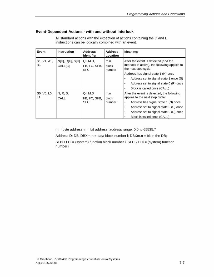
Programming Actions and Conditions
S7 Graph for S7-300/400 Programming Sequential Control SystemsA5E00105265-01 7-7
Event-Dependent Actions - with and without Interlock
All standard actions with the exception of actions containing the D and Linstructions can be logically combined with an event.
Event Instruction AddressIdentifier
AddressLocation
Meaning:
S1, V1, A1,R1
N[C], R[C], S[C]
CALL[C]
Q,I,M,D,
FB, FC, SFB,SFC
m.n
blocknumber
After the event is detected [and theinterlock is active], the following applies tothe next step cycle:
Address has signal state 1 (N) once
• Address set to signal state 1 once (S)
• Address set to signal state 0 (R) once
• Block is called once (CALL)
S0, V0, L0,L1
N, R, S,
CALL
Q,I,M,D
FB, FC, SFB,SFC
m.n
blocknumber
After the event is detected, the followingapplies to the next step cycle:
• Address has signal state 1 (N) once
• Address set to signal state 0 (S) once
• Address set to signal state 0 (R) once
• Block is called once (CALL)
m = byte address; n = bit address; address range: 0.0 to 65535.7
Address D: DBi.DBXm.n = data block number i; DBXm.n = bit in the DB;
SFBi / FBi = (system) function block number i; SFCi / FCi = (system) functionnumber i
05.04.0105.04.200105.04.2001

Programming Actions and Conditions
S7 Graph for S7-300/400 Programming Sequential Control Systems7-8 A5E00105265-01
Event-Dependent Actions - to Activate and Deactivate Steps
Other steps can be activated or deactivated using the ON and OFF instructions.The instructions are always dependent on a step event, in other words the eventdetermines the time at which the step is activated or deactivated.
These instructions can be combined with an interlock. The actions are onlyexecuted when the conditions of the interlock are satisfied.
Event Instruction AddressIdentifier
AddressLocation
Meaning:
S1, V1, A1,R1
ON[C], OFF[C] S i Activate (ON) or deactivate (OFF) the stepdependent on the event [and interlock]
S1, V1 OFF[C] S_ALL Deactivate all steps dependent on theevent [andinterlock]. The exception to this is the stepin which the action is located.
S0, V0, L0,L1
ON, OFF S i Activate (ON) or deactivate (OFF)dependent onthe event
L1 OFF S_ALL Deactivate all steps dependent on theevent. The exception to this is the step inwhich the action is located.
i: step number
Note
If a step is both activated and deactivated in one cycle, deactivating has higherpriority.
Example: Action Table with Event-Dependent Actions
S1 RC
L0 CALL
A1.0
FC10
S4
V1 OFF S_ALL
Step 4Step 4
1
2
3
(1): As soon as the step is active and the interlock is satisfied, output Q1.0 is set to0 and remains set to 0.
(2): As soon as the supervision error occurs, all active steps are deactivated,except for step S4 in which the action is located.
(3): As soon as the interlock condition is satisfied, the specified block (FC10) iscalled.
05.04.0105.04.200105.04.2001

Programming Actions and Conditions
S7 Graph for S7-300/400 Programming Sequential Control SystemsA5E00105265-01 7-9
7.4 Counters, Timers, and Arithmetic in Actions
Counters in Actions
All counters in actions are always dependent on an event, in other words the eventdetermines the time at which the instruction is activated. You also have the optionof combining counters with an interlock. The count instructions combined with theinterlock are only executed when the conditions of the interlock are satisfied (letterC added) as well as the event occurring. Counters without an interlock areexecuted when the event occurs.
The counters in actions behave like the counters in other S7 programminglanguages: There is no overflow and no underflow and with a counter reading of 0,the counter bit is also 0, otherwise it is 1.
Event Instruction AddressIdentifier
AddressLocation
Meaning:
S1, S0, L1,L0, V1, V0,A1, R1
CS[C] C X Set: As soon as the event occurs [and theinterlock is satisfied], the initial countervalue is loaded in the counter.
<initial countervalue>
Initial counter value
S1, S0, L1,L0, V1, V0,A1, R1
CU[C] C X Count up: As soon as the event occurs [andthe interlock is satisfied], the counter valueis incremented by "1".
S1, S0, L1,L0, V1, V0,A1, R1
CD[C] C X Count down: As soon as the event occurs[and the interlock is satisfied], the countervalue is decremented by "1".
S1, S0, L1,L0, V1, V0,A1, R1
CR[C] C X Reset: As soon as the event occurs [andthe interlock is satisfied], the counter valueis reset to 0.
[ ] = optional supplement to interlock; x = number of the counter
Initial Counter Value
All actions containing the CS instruction require an initial counter value. The initialcounter value is programmed with the following syntax:
<initial counter value> = IWy, QWy, MWy, LWy, DBWy, DIWy; variable of typeWORD; C#0 ... C#999
Y = 0 ... 65534
05.04.0105.04.200105.04.2001

Programming Actions and Conditions
S7 Graph for S7-300/400 Programming Sequential Control Systems7-10 A5E00105265-01
Timers in Actions
All timers in actions are always dependent on an event, in other words the eventdetermines the time at which the instruction is activated. You also have the optionof combining timers with an interlock. The timer instructions combined with aninterlock are only executed when the conditions of the interlock are satisfied inaddition to the event occurring (additional letter C). Timers without an interlock areexecuted when the event occurs.
Event Instruction AddressIdentifier
AddressLocation
Meaning:
S1, S0, L1,L0, V1, V0,A1, R1
TL[C] T X Extended pulse, non-latching behavior of thetimer bit (status of the timer): As soon as theevent occurs, the timer starts. The condition Cis only relevant for the point at which the timerstarts. Once the timer starts, it continues torun regardless of the interlock and stepactivity. During the period <time>, the timer bitis set to "1", afterwards it is reset to "0". Thestarted timer can be restarted by an eventoccurring. The timer bit remains set to "1", thetimer starts again with the value of <time>.
<time> time
S1, S0, L1,L0, V1, V0,A1, R1
TD[C] T X Latching on delay, latching behavior of thetimer bit (status of the timer): As soon as theevent occurs, the timer starts. The condition Cis only relevant for the point at which the timerstarts. Once the timer starts, it continues torun regardless of the interlock and stepactivity. During the <time>, the timer bit is setto "0". The started timer can be restarted byan event occurring. The timer bit remains setto "0", the total time the timer runs is extendedby <time>. The timer bit is set to "1" only afterthe total time has elapsed.
<time> time
S1, S0, L1,L0, V1, V0,A1, R1
TR[C] T X Reset: As soon as the event occurs [and theinterlock is satisfied], the timer is stopped.Timer bit (status of the timer) and timer valueare reset to "0".
[ ] = optional supplement to interlock; x = number of the timer

Programming Actions and Conditions
S7 Graph for S7-300/400 Programming Sequential Control SystemsA5E00105265-01 7-11
Time (duration)
All actions containing one of the TL or TD instructions require a time (duration) tobe specified. The time is programmed with the following syntax:
<time> = IWy, QWy, MWy, LWy, DBWy, DIWy; variable of the type S5TIME,WORD; S5T#time_cnstant
Y = 0 ... 65534
Arithmetic in Actions
You can provide statements with simple arithmetic expressions in actions. Thereare assignments in the form A:=B, A:=func(B) and A:=B<operator>C. An actioncontaining an arithmetic expression requires the N instruction. The action can bedependent on an event. This means that the assignment can either be executedonly when the relevant event occurs or in each cycle in which the step is active. Asan option, the action can also be combined with an interlock (letter C added).
Event Instruction Assignment Meaning
-- N[C] A:=B
A:=func(B)
A:=B<operator>C
As long as the step is active [and the interlock issatisfied], the assignment is executed.
S0, S1, V0,V1, L0, L1,A1, R1
N[C] A:=B
A:=func(B)
A:=B<operator>C
After the event occurs [and the interlock is true], theassignment is executed.
Direct Assignments
You can enter direct assignments with the syntax A:=B. The following data typescan be used for a direct assignment:
• 8 bits: BYTE, CHAR
• 16 bits: WORD, INT, DATE, S5TIME
• 32 bits: DWORD, DINT, REAL, TIME, TIME_OF_DAY
The following table is an overview of all the permitted types of assignment. You canassign not only addresses of the same type but also addresses with different datatypes with the same length and addresses of different lengths to each other:
05.04.0105.04.200105.04.2001
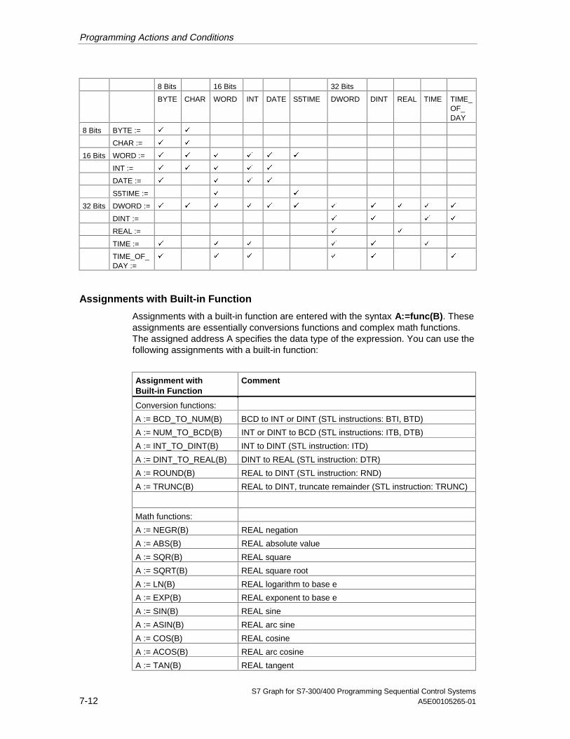
Programming Actions and Conditions
S7 Graph for S7-300/400 Programming Sequential Control Systems7-12 A5E00105265-01
8 Bits 16 Bits 32 Bits
BYTE CHAR WORD INT DATE S5TIME DWORD DINT REAL TIME TIME_OF_DAY
8 Bits BYTE := á á
CHAR := á á
16 Bits WORD := á á á á á á
INT := á á á á á
DATE := á á á á
S5TIME := á á
32 Bits DWORD := á á á á á á á á á á á
DINT := á á á á
REAL := á á
TIME := á á á á á á
TIME_OF_DAY :=
á á á á á á
Assignments with Built-in Function
Assignments with a built-in function are entered with the syntax A:=func(B). Theseassignments are essentially conversions functions and complex math functions.The assigned address A specifies the data type of the expression. You can use thefollowing assignments with a built-in function:
Assignment withBuilt-in Function
Comment
Conversion functions:
A := BCD_TO_NUM(B) BCD to INT or DINT (STL instructions: BTI, BTD)
A := NUM_TO_BCD(B) INT or DINT to BCD (STL instructions: ITB, DTB)
A := INT_TO_DINT(B) INT to DINT (STL instruction: ITD)
A := DINT_TO_REAL(B) DINT to REAL (STL instruction: DTR)
A := ROUND(B) REAL to DINT (STL instruction: RND)
A := TRUNC(B) REAL to DINT, truncate remainder (STL instruction: TRUNC)
Math functions:
A := NEGR(B) REAL negation
A := ABS(B) REAL absolute value
A := SQR(B) REAL square
A := SQRT(B) REAL square root
A := LN(B) REAL logarithm to base e
A := EXP(B) REAL exponent to base e
A := SIN(B) REAL sine
A := ASIN(B) REAL arc sine
A := COS(B) REAL cosine
A := ACOS(B) REAL arc cosine
A := TAN(B) REAL tangent
05.04.0105.04.200105.04.2001
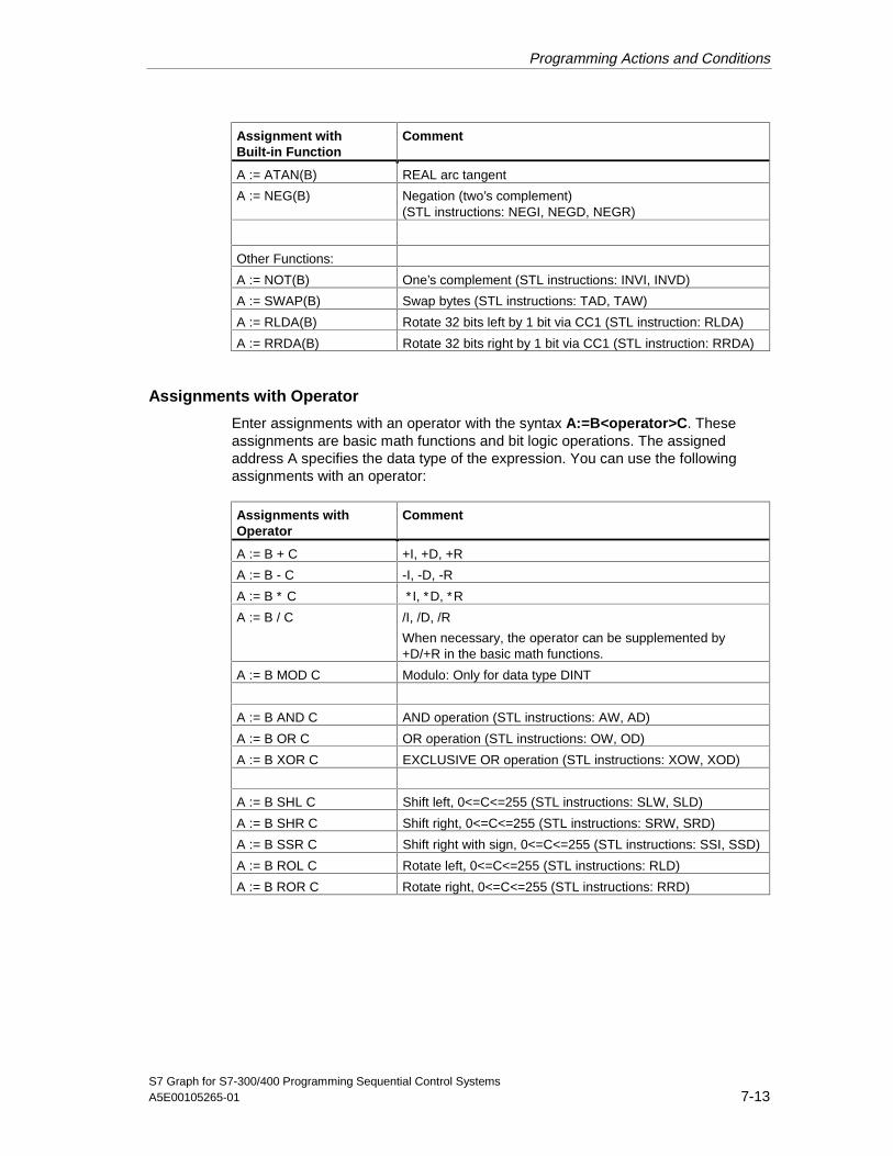
Programming Actions and Conditions
S7 Graph for S7-300/400 Programming Sequential Control SystemsA5E00105265-01 7-13
Assignment withBuilt-in Function
Comment
A := ATAN(B) REAL arc tangent
A := NEG(B) Negation (two’s complement)(STL instructions: NEGI, NEGD, NEGR)
Other Functions:
A := NOT(B) One’s complement (STL instructions: INVI, INVD)
A := SWAP(B) Swap bytes (STL instructions: TAD, TAW)
A := RLDA(B) Rotate 32 bits left by 1 bit via CC1 (STL instruction: RLDA)
A := RRDA(B) Rotate 32 bits right by 1 bit via CC1 (STL instruction: RRDA)
Assignments with Operator
Enter assignments with an operator with the syntax A:=B<operator>C. Theseassignments are basic math functions and bit logic operations. The assignedaddress A specifies the data type of the expression. You can use the followingassignments with an operator:
Assignments withOperator
Comment
A := B + C +I, +D, +R
A := B - C -I, -D, -R
A := B ∗ C ∗I, ∗D, ∗R
A := B / C /I, /D, /R
When necessary, the operator can be supplemented by+D/+R in the basic math functions.
A := B MOD C Modulo: Only for data type DINT
A := B AND C AND operation (STL instructions: AW, AD)
A := B OR C OR operation (STL instructions: OW, OD)
A := B XOR C EXCLUSIVE OR operation (STL instructions: XOW, XOD)
A := B SHL C Shift left, 0<=C<=255 (STL instructions: SLW, SLD)
A := B SHR C Shift right, 0<=C<=255 (STL instructions: SRW, SRD)
A := B SSR C Shift right with sign, 0<=C<=255 (STL instructions: SSI, SSD)
A := B ROL C Rotate left, 0<=C<=255 (STL instructions: RLD)
A := B ROR C Rotate right, 0<=C<=255 (STL instructions: RRD)
05.04.0105.04.200105.04.2001

Programming Actions and Conditions
S7 Graph for S7-300/400 Programming Sequential Control Systems7-14 A5E00105265-01
Example: Action Table with Counters and Arithmetic
S1 CU Z23S4
S1 N A:=A+1
Step 4Step 4
1
2
Two alternatives for counting production cycles:
(1): As soon as the step is active, the counter C23 is incremented by 1. Thecounter therefore counts the number of times the step is activated.
(2): As soon as the step becomes active, the value of A is incremented by 1. In thisway, the arithmetic can be used to count actions based on the number ofactivations of the step.
7.5 Conditions
Conditions are binary states of the process that are combined with each other asLAD or FBD elements (normally-open contact, normally-closed contact, AND box,OR box, comparator) in the LAD diagram or in the function block diagramaccording to Boolean logic. The result of the logic operation (RLO) can influenceindividual actions of a step, the entire step, the enabling of the next step or theentire sequencer. Logic operations are programmed in Ladder Logic or FBD.
Conditions are :
• Events (for example active step is exited) and
• States (for example input I2.1 is set)
Areas in which Conditions Can Occur
Conditions occur in the following areas:
• Transition (enabling the next step)
• Interlock
• Supervision
• Permanent instructions (conditions and block calls at the start and/or at the endof the sequencer)
05.04.0105.04.200105.04.2001

Programming Actions and Conditions
S7 Graph for S7-300/400 Programming Sequential Control SystemsA5E00105265-01 7-15
Transition
In a transition, you program conditions that control how the sequencer passescontrol from one step to the next.
Interlock
Supervision
S1Step1
V
T1Trans1
E2.3
E2.5
C
S1 RC
L0 CALL
A1.0
FC10
V1 OFF S_ALL
Step1
A transition is displayed and programmed at the single step display level. You canalso select the "Sequencer" display level and display the transitions with the menucommand View > Display With > Conditions and Actions.
The transition passes control to the next step of the sequencer when the logicoperation of the conditions is satisfied, in other words when the network producesthe result 1. The step following the transition becomes active.
The transition does not pass control to the next step of the sequencer if the logicoperation of the conditions is not satisfied; in other words, when the networkproduces the result 0. The active step remains active.
Empty Transition
Transitions without programmed conditions are empty transitions. This does notaffect the execution of the sequencer. The active step is run through only once.The following step becomes valid.
Skipping Steps
If both the transition before a step and the transition after a step are valid at thesame time, the step does not become active.
In the "Compile/Save" tab of the "Block Settings" dialog box (menu commandOptions > Block Settings), the option "Skip Steps" must be selected.
05.04.0105.04.200105.04.2001

Programming Actions and Conditions
S7 Graph for S7-300/400 Programming Sequential Control Systems7-16 A5E00105265-01
Interlock
An interlock is a programmable condition for interlocking the step that influencesthe execution of individual actions.
Interlock
Supervision
S1Step1
V
C
T1Trans1
E2.3 E2.5
C
S1 RC
L0 CALL
A1.0
FC10
V1 OFF S_ALL
Step1
If the logic operation of the conditions is satisfied, the actions combined withinterlocks are executed.
If the logic operation of the conditions is not satisfied, there is a disturbance:
• Actions combined with an interlock are not executed
• An interlock error is signaled (event L1).
You program an interlock at the single step display level. A maximum of 32 LadderLogic/FBD elements can be programmed per interlock. The result of the operationis managed automatically by the system.
A programmed interlock is indicated by the letter C following the step at all displaylevels.
Caution
If you program an interlock this is only used in the actions when their instructionshave been extended by the letter C.
Empty Interlock
An interlock without a condition (in other words without Ladder Logic or FBDelements) behaves like a satisfied interlock.
05.04.0105.04.200105.04.2001
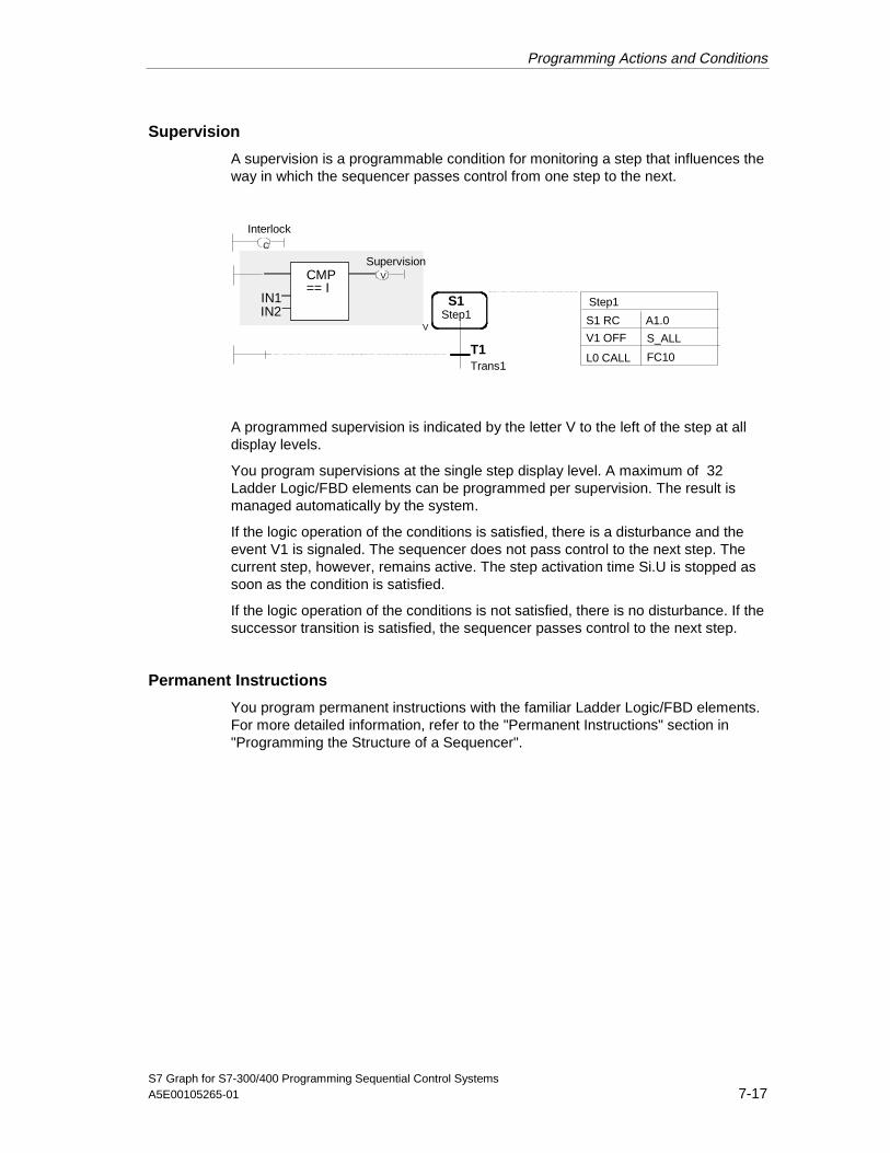
Programming Actions and Conditions
S7 Graph for S7-300/400 Programming Sequential Control SystemsA5E00105265-01 7-17
Supervision
A supervision is a programmable condition for monitoring a step that influences theway in which the sequencer passes control from one step to the next.
Interlock
Supervision
S1Step1
V
C
T1Trans1
V
IN1IN2
CMP== I
S1 RC
L0 CALL
A1.0
FC10
V1 OFF S_ALL
Step1
A programmed supervision is indicated by the letter V to the left of the step at alldisplay levels.
You program supervisions at the single step display level. A maximum of 32Ladder Logic/FBD elements can be programmed per supervision. The result ismanaged automatically by the system.
If the logic operation of the conditions is satisfied, there is a disturbance and theevent V1 is signaled. The sequencer does not pass control to the next step. Thecurrent step, however, remains active. The step activation time Si.U is stopped assoon as the condition is satisfied.
If the logic operation of the conditions is not satisfied, there is no disturbance. If thesuccessor transition is satisfied, the sequencer passes control to the next step.
Permanent Instructions
You program permanent instructions with the familiar Ladder Logic/FBD elements.For more detailed information, refer to the "Permanent Instructions" section in"Programming the Structure of a Sequencer".
05.04.0105.04.200105.04.2001
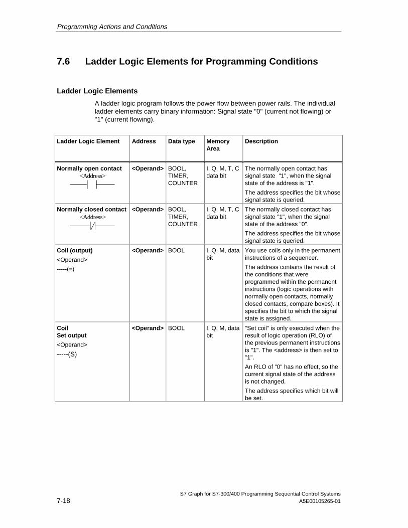
Programming Actions and Conditions
S7 Graph for S7-300/400 Programming Sequential Control Systems7-18 A5E00105265-01
7.6 Ladder Logic Elements for Programming Conditions
Ladder Logic Elements
A ladder logic program follows the power flow between power rails. The individualladder elements carry binary information: Signal state "0" (current not flowing) or"1" (current flowing).
Ladder Logic Element Address Data type MemoryArea
Description
Normally open contact<Address>
<Operand> BOOL,TIMER,COUNTER
I, Q, M, T, Cdata bit
The normally open contact hassignal state "1", when the signalstate of the address is "1".
The address specifies the bit whosesignal state is queried.
Normally closed contact<Address>
<Operand> BOOL,TIMER,COUNTER
I, Q, M, T, Cdata bit
The normally closed contact hassignal state "1", when the signalstate of the address "0".
The address specifies the bit whosesignal state is queried.
Coil (output)
<Operand>
-----(=)
<Operand> BOOL I, Q, M, databit
You use coils only in the permanentinstructions of a sequencer.
The address contains the result ofthe conditions that wereprogrammed within the permanentinstructions (logic operations withnormally open contacts, normallyclosed contacts, compare boxes). Itspecifies the bit to which the signalstate is assigned.
CoilSet output
<Operand>
-----(S)
<Operand> BOOL I, Q, M, databit
"Set coil" is only executed when theresult of logic operation (RLO) ofthe previous permanent instructionsis "1". The <address> is then set to"1".
An RLO of "0" has no effect, so thecurrent signal state of the addressis not changed.
The address specifies which bit willbe set.
05.04.0105.04.200105.04.2001

Programming Actions and Conditions
S7 Graph for S7-300/400 Programming Sequential Control SystemsA5E00105265-01 7-19
Ladder Logic Element Address Data type MemoryArea
Description
CoilReset output
<Operand>
-----(R)
<Operand> BOOL I, Q, M, databit
"Reset coil" is only executed whenthe result of logic operation (RLO)of the previous permanentinstructions is "1". The <address> isthen set to "0".
An RLO of "0" has no effect, so thecurrent signal state of the addressis not changed.
The address specifies which bit willbe reset.
Rules for Entering Ladder Logic Elements
When entering Ladder elements, keep to the following rules:
• All elements and branches must be connected together.
• Each branch in a Ladder Logic network must contain at least one Ladder Logicelement.
Modes for Inserting Ladder Elements
There are two editing modes available for inserting Ladder elements:
• Insert > Direct In this mode, you first select the position in the sequencer atwhich you want to insert an element and then select the element to beinserted.
• Insert > Drag and Drop In this mode, you first select the element you want toinsert and then select the position at which the element will be inserted usingthe mouse pointer. This mode is particularly suitable when you want to insertthe same element at more than one position in the sequencer.
Entering Addresses
There are two ways of entering addresses:
• Click the placeholder "??.?" of the required text field. Then enter an absolute orsymbolic address (for example I1.0, "limit_switch"). You can use both theGerman mnemonics (E, A) and the English mnemonics (I, O) for addresses.Set the mnemonics you require in the SIMATIC Manager.
• Select the address and then select an absolute or symbolic address from thedrop-down list box (for example I1.0, "Limit switch"). The address is thenentered.
05.04.0105.04.200105.04.2001

Programming Actions and Conditions
S7 Graph for S7-300/400 Programming Sequential Control Systems7-20 A5E00105265-01
Changing Over Between Ladder Logic and FBD
In S7 Graph, you can program conditions in one of two programming languages: Inladder diagram (LAD) or in function block diagram (FBD). You can display theconditions in LAD or in FBD at any time. To toggle the display, simply select theappropriate menu command: View > LAD or View > FBD.
7.7 Logic Operations with Ladder Logic Elements
A logic operation queries the signal state of a Ladder element for "0" (not activated,off) or "1" (activated, on) and then supplies a result of logic operation (RLO). Theinstruction either saves the result or executes a Boolean logic operation with it.
The two logic operations AND and OR must be distinguished:
Logic operation Example of a logic operation in a transition
AND E0.0 E0.1 The condition is satisfied whenthe signal state at input I ’0.0 is"1" AND and the signal state atinput I 0.1 is "0".
OR E0.0
IN1IN2
CMP== I
The condition is satisfied when
• The signal state at input I 0.0is "1"OR
• The compare box producesthe result “true" aftercomparing the twoaddresses.
05.04.0105.04.200105.04.2001

Programming Actions and Conditions
S7 Graph for S7-300/400 Programming Sequential Control SystemsA5E00105265-01 7-21
Ladder LogicElement
Addresses Data Memory Area Description
Compare box
IN1
IN2
CMP==
= =
><
> =
< =
< >
INTDINTREAL
IN1: Firstcomparison value
INT/ DINT/ REAL/TIMER/ CONST
I, Q, M, data(double) word
The compare boxhas the signal state"1" when thecomparisonbetween the twoaddresses IN1 andIN2 is true.
INT: 16-bit integercomparatorParameter: words
DINT: 32-bit integercomparator andcomparator fortimers Parameter:double words,timers
REAL: 32-bitfloating-pointnumber comparatorParameter: doublewords
IN2: Secondcomparison value
INT / DINT / REAL /TIMER / CONST
I, Q, M, data(double) word
Note:
When you enter thecomparator you onlyneed to specify thedata type D/R/Iexplicitly when youenter the 32 bitvalues withoutspecifying a type(for example whenaccessing absoluteaddresses in thedouble word area).Otherwise the datatype is detected bythe system so thatthe specification canbe omitted.
05.04.0105.04.200105.04.2001

Programming Actions and Conditions
S7 Graph for S7-300/400 Programming Sequential Control Systems7-22 A5E00105265-01
7.8 FBD Elements for Programming Conditions
FBD Elements
An FBD program follows the signal flow of a logic string. The individual FBDelements carry binary information: Signal state "0" (current not flowing) or "1"(current flowing).
FBD Element Address Data type MemoryArea
Description
Insert binary input
<Address>
<Operand> BOOL I, Q, M, T,C, D, L
The instruction adds a furtherbinary input to an AND or OR boxafter the position selected.
The address specifies the bitwhose signal state is queried.
Negate binary input None: -- -- The instruction negates the resultof logic operation (RLO).
Output You use output operations only inthe permanent instructions of asequencer.
Assign output
<Address> =
<Operand> BOOL I, Q, M, D, L The address contains the result ofthe conditions that wereprogrammed within the permanentinstructions (logic operationsbefore the output box). It specifiesthe bit to which the signal state isassigned.
Set output
<Address> S
<Operand> BOOL I, Q, M, D, L This instruction is executed onlywhen the RLO of the previouspermanent instruction is "1". The<address> is then set to "1".
An RLO of "0" has no effect, so thecurrent signal state of the addressis not changed.
The address specifies which bit willbe set.
Reset output
<Address> R
<Operand> BOOL,TIMER,COUNTER
I, Q, M, T,C, D, L
This instruction is executed onlywhen the RLO of the previouspermanent instruction is "1". The<address> is then reset to "0".
An RLO of "0" has no effect, so thecurrent signal state of the addressis not changed.
The address specifies which bit willbe reset.
05.04.0105.04.200105.04.2001
Programming Actions and Conditions
S7 Graph for S7-300/400 Programming Sequential Control SystemsA5E00105265-01 7-23
Rules for Entering FBD Elements
When entering FBD elements, keep to the following rules:
• All elements and branches must be connected together.
• Each branch in an FBD network must contain at least one FBD element.
Modes for Inserting FBD Elements
There are two editing modes available for inserting FBD elements:
• Insert > Direct In this mode, you first select the position in the sequencer atwhich you want to insert an element and then select the element to beinserted.
• Insert > Drag and Drop In this mode, you first select the element you want toinsert and then select the position at which the element will be inserted usingthe mouse pointer. This mode is particularly suitable when you want to insertthe same element at more than one position in the sequencer.
Entering Addresses
There are two ways of entering addresses:
• Click the placeholder "??.?" of the required text field. Then enter an absolute orsymbolic address (for example I1.0, "limit_switch"). You can use both theGerman mnemonics (E, A) and the English mnemonics (I, O) for addresses.Set the mnemonics you require in the SIMATIC Manager.
• Select the address and then select an absolute or symbolic address from thedrop-down list box (for example I1.0, "Limit switch"). The address is thenentered.
Changing Over Between FBD and Ladder Logic Diagram
In S7 Graph, you can program conditions in one of two programming languages: Inladder diagram (LAD) or in function block diagram (FBD). You can display theconditions in LAD or in FBD at any time. To toggle the display, simply select theappropriate menu command: View > LAD or View > FBD.
05.04.0105.04.200105.04.2001

Programming Actions and Conditions
S7 Graph for S7-300/400 Programming Sequential Control Systems7-24 A5E00105265-01
Logic Operations with FBD Elements
The two logic operations AND and OR must be distinguished: Here, two FBDelements are available.
FBD Element Address Data type MemoryArea
Description
AND operation
<Address><Address>
&
<Operand> BOOL I, Q, M, T,C, D, L
The instruction provides the signal"1" when the signal state of all<addresses> is "1". If the signalstate of an <address> is "0", theinstruction produces the result "0".
The address specifies the bitwhose signal state is queried.
OR operation
<Address><Address> >=1
<Operand> BOOL I, Q, M, T,C, D, L
The instruction provides the signal"1" when the signal state of one ofthe <addresses> is "1". If the signalstate of all <address> is "0", theinstruction produces the result "0".
The address specifies the bitwhose signal state is queried.
Compare box
IN1
IN2
CMP==
= =
><
> =
< =
< >
INTDINTREAL
IN1: Firstcomparisonvalue
INT/ DINT/REAL
I, Q, M, D,L, constant
The result of the logic operationhas the signal state "1" when thecomparison between the twoaddresses IN1 and IN2 is true.
INT: 16-bit integer comparison :Parameter words
DINT: 32-bit integer comparison :Parameter double words
REAL: 32-bit floating-point numbercomparisonParameter: double words
IN2:Secondcomparisonvalue
INT / DINT /REAL
I, Q, M, D,L, constant
Note:
When you enter the comparatoryou only need to specify the datatype D/R/I explicitly when you enterthe 32 bit values without specifyinga type (for example whenaccessing absolute addresses inthe double word area). Otherwisethe data type is detected by thesystem so that the specificationcan be omitted.
05.04.0105.04.200105.04.2001
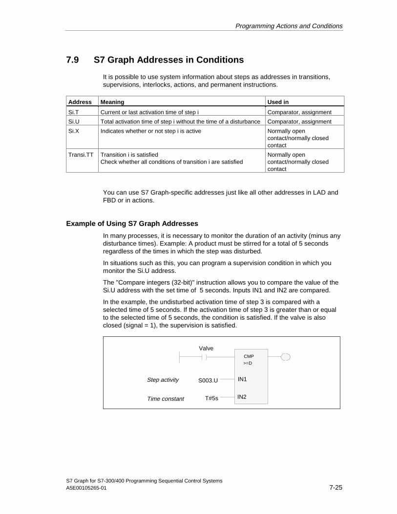
Programming Actions and Conditions
S7 Graph for S7-300/400 Programming Sequential Control SystemsA5E00105265-01 7-25
7.9 S7 Graph Addresses in Conditions
It is possible to use system information about steps as addresses in transitions,supervisions, interlocks, actions, and permanent instructions.
Address Meaning Used in
Si.T Current or last activation time of step i Comparator, assignment
Si.U Total activation time of step i without the time of a disturbance Comparator, assignment
Si.X Indicates whether or not step i is active Normally opencontact/normally closedcontact
Transi.TT Transition i is satisfiedCheck whether all conditions of transition i are satisfied
Normally opencontact/normally closedcontact
You can use S7 Graph-specific addresses just like all other addresses in LAD andFBD or in actions.
Example of Using S7 Graph Addresses
In many processes, it is necessary to monitor the duration of an activity (minus anydisturbance times). Example: A product must be stirred for a total of 5 secondsregardless of the times in which the step was disturbed.
In situations such as this, you can program a supervision condition in which youmonitor the Si.U address.
The "Compare integers (32-bit)" instruction allows you to compare the value of theSi.U address with the set time of 5 seconds. Inputs IN1 and IN2 are compared.
In the example, the undisturbed activation time of step 3 is compared with aselected time of 5 seconds. If the activation time of step 3 is greater than or equalto the selected time of 5 seconds, the condition is satisfied. If the valve is alsoclosed (signal = 1), the supervision is satisfied.
CMP
>=D
Step activity
Time constant
S003.U
T#5s
Valve
IN1
IN2
05.04.0105.04.200105.04.2001

Programming Actions and Conditions
S7 Graph for S7-300/400 Programming Sequential Control Systems7-26 A5E00105265-01
7.10 Supervision Errors and Acknowledgment
Every step can be assigned a supervision condition. Only active step aremonitored. S7 Graph recognizes whether or not the supervision conditions aresatisfied (in other words when a supervision error has occurred).
A supervision error entering the state (1) results in event "V1", a supervision errorleaving the state (2) results in the event "V0".
1
0t
V1 V0
Disturbance No disturbance
1 2
Disturbance: conditions in the supervision are satisfiedNo disturbance: conditions in the supervision are not satisfied
Signaling and Acknowledgment - Requirements
The signaling and acknowledgment of a supervision error is only possible with thefollowing settings in the "Compile / Save" tab of the "Block Settings" dialog (menucommand Options > Block Settings):
• "Standard", "Maximum", or "Definable" is set in the "FB Parameters" box.S7 Graph then signals a supervision error with the output parameterERR_FLT.
• "Acknowledge errors" is set in the "Sequencer Properties" group.This means that supervision errors occurring during operation must beacknowledged with the input parameter ACK_EF.
Whether or not an error must be acknowledged can be set as "definable" not onlyin the settings in the dialog box but alternatively also using the relevant parameter(EN_ACKREQ) in the parameter set.
Handling Supervision Errors
Errors that must be acknowledged affect only the relevant sequencer paths, so thatthe remaining sequencer can be processed while the sequencer path affected isonly processed again after the error is acknowledged.
05.04.0105.04.200105.04.2001

Programming Actions and Conditions
S7 Graph for S7-300/400 Programming Sequential Control SystemsA5E00105265-01 7-27
Supervision error occurs(event V1 enters state)
Actions with V1 are executed once in thenext sequencer cycle.
Step activation time Si.U is stopped
Compilationsetting:Acknowledge
Message in FB parameter ERR_FLT
Ackn. signal?
Ackn. signal orSV not true?
Si.U:=0
SV not true?
Step enablingcondition true?
Supervision errorleaves state
Event V0 enters
End
Sequencer switches
Supervision errorleaves state
Event V0 enters
Ackn. signal?
Si.U:=0
SV not true?
Step enablingcondition true?
No
Yes No
Yes
Yes Yes
Yes
Yes Yes
Yes
No
No
No
NoNo
No
Supervision errorleaves state
Event V0 enters
05.04.0105.04.200105.04.2001

Programming Actions and Conditions
S7 Graph for S7-300/400 Programming Sequential Control Systems7-28 A5E00105265-01
7.11 Comment, Extended Name, Number, Name
Step Comment
A step comment can contain a maximum of 2048 characters. It has no influence onthe execution of the program.
Step comments are displayed only at the single step display level. If you do notenter an extended step name, the step name is displayed instead.
The Extended Name
The extended name is displayed in the text line above the actions. It can be used,on the one hand, as a simple comment, and on the other hand the extended namecan also be used instead of the step name to identify the step to the diagnosticsystem.
The number of characters in the extended name is not limited. Make sure,however, that you assign extended names that are unique in the program.
If you do not enter an extended name, the step name is displayed instead.
Step Number (for example S1) and Step Name (for example Step1)
The step name and step number must be unique and can be adapted at any of thedisplay levels.
• The step number is automatically assigned by the system (range: 1 to 999).If the step number of the first step is set manually in a branch path, whenfurther step-transition pairs are inserted, the numbers are assignedautomatically by the system in ascending order starting at the manuallyentered number. This simply leads to interrupted numbering of the step-transition pairs. You can renumber the steps and transitions at any time so thatindividual areas are consecutively numbered.
• The step name is automatically assigned by the system (range: step1 tostep999).It can consist of a maximum of 24 alphanumeric characters. The first charactermust be a letter. If the zoom factor is too low, the display of step names issuppressed.If you modify the name of a step in the "Step Properties" dialog box, S7 Graphautomatically searches for the old name and replaces it throughout the entireprogram when you save or compile. All instructions in which the step isreferenced are therefore updated.
05.04.0105.04.200105.04.2001

Programming Actions and Conditions
S7 Graph for S7-300/400 Programming Sequential Control SystemsA5E00105265-01 7-29
Transition Number (for example T1) and Transition Name (for example Trans1)
The transition name and transition number must be unique and can be adaptedlater in all three programming language representations.
• The transition number is assigned automatically by the system (range: 1 to999).If the transition number of the first transition is assigned manually in a branchpath, when you insert further step-transition pairs, the numbers are assignedby the system automatically starting at the number entered manually. Thissimply leads to interrupted numbering of the step-transition pairs. You canrenumber the steps and transitions at any time so that individual areas areconsecutively numbered.
• The transition name is automatically assigned by the system (range: Trans1 toTrans999).It can consist of a maximum of 24 alphanumeric characters. The first charactermust be a letter. If the zoom factor is too low, the display of the transition nameis suppressed. You can modify the transition name in the "TransitionProperties" dialog box.
7.12 Programming with Symbolic Addresses
To make the program and sequential control system clearer, you can useaddresses with symbolic identifiers or names instead of absolute addresses.
Setting the Address Priority
Symbolic addresses are assigned in the symbol table. You can add furthersymbolic addresses to the symbol table that you define while creating thesequencer with S7 Graph.
The symbol table is automatically created in the S7 program and can be displayedusing the menu command Options > Symbol Table or in the SIMATIC managerusing the "Symbols" folder.
The symbols used are displayed in the symbols folder in the "Variables" tab of theoverview window. The corresponding addresses, data types, and comments aredisplayed in the "Variables" tab of the details window.
Requirements for Using Symbolic Addresses
Symbolic addresses can only be used when a symbolic name has been assignedto the absolute addresses in the symbol table.
05.04.0105.04.200105.04.2001

Programming Actions and Conditions
S7 Graph for S7-300/400 Programming Sequential Control Systems7-30 A5E00105265-01
Displaying Symbol Information when Entering Addresses
You can simplify the entry of symbolic addresses in conditions and actions bydisplaying existing symbols in a drop-down list box. If the menu command View >Display with > Symbol List is selected, the list box with the symbols is displayedautomatically when you enter addresses. If the menu command is not selected,you can open the list box with the symbols at any time using the right mouse buttonand the Insert Symbol command.
Example of Using Symbolic Names
• Instead of the address I0.1, use the defined name “Dr_mot_stopped" or
• Instead of the absolute block identifier FB11, use the symbolic name“Seq_drill".
7.13 Editing Variables
You can edit variables in the "Variables" tab in S7 Graph. This tab is displayed inthe "Overview" window to the left of the working area. You can toggle the displayon or off with the View > Overviews menu command.
You can modify existing parameter sets in the "Variables" tab. You can also defineyour own parameters and variables. You can delete, but not edit systemparameters.
In most cases, you only require the information that is displayed in the "Variables"tab of the overview window. You can obtain more detailed information on thevariables in the "Details" window. This window also contains a "Variables" tab inwhich you can see information about addresses, initial values, and comments onthe variables.
You can display detailed help on declaring variables in the "Variables" tab bypressing the F1 key.
Inserting Parameters in the Sequencer
If you want to use a parameter or variable in the sequencer, you can drag theparameter or variable from the "Variables" tab to the sequencer using the mouseand position it at the required location.
Automatic Updating of Changes
Changes you have made to the parameters or variables in the "Variables" tab areautomatically updated in the sequencer so that no inconsistencies can result.
05.04.0105.04.200105.04.2001

S7 Graph for S7-300/400 Programming Sequential Control SystemsA5E00105265-01 8-1
8 Saving and Compiling
Principle: Saving and Compiling
After you have programmed a sequencer, you must save the program. Whensaving and compiling, S7 Graph makes a distinction between an S7 Graph FB andan S7 Graph source file.
Syntax check
Trigger: Save an FB
Error?Yes
No
Trigger: Save a sourcefile
Trigger: Compile asource file
Error messages
Correction of errors
FB is created
Instance DB is created
Source file is saved
8.1 Saving and Compiling
Make sure that you keep to the following rules:
• The size of an S7 Graph FB with sequencers is restricted for all
- CPU 3xx to a maximum of 8 Kbytes or 16 Kbytes.
- CPU 4xx to 64 Kbytes.
• Each FB has an instance DB that can be understood as the memory of the FB.This contains all the data and parameters required to execute the FB. Theinstance DB can be created either automatically during compilation or laterusing a menu command.
• The size of the instance DB depends on the number of programmed steps andtransitions but is a minimum of 300 bytes.
05.04.0105.04.200105.04.2001
Saving and Compiling
S7 Graph for S7-300/400 Programming Sequential Control Systems8-2 A5E00105265-01
• Before saving the S7 Graph FB or S7 Graph source file, you can start aconsistency check.
- Errors and warnings during the compilation of an S7 Graph source file canbut do not need to be corrected.
- Errors during the compilation of an S7 Graph FB must, however, becorrected before the FB can be saved.
• If you want to download several sequencers to the PLC at the same time, it isoften better to include the system functionality in one of the supplied standardblocks. This reduces the size of every S7 Graph block by approximately 5000bytes. The requirement of the standard block must, however, be added to this(once) (FC70 approx. 8200 bytes, FC71 approx. 7750 bytes, FC72 approx.10700 bytes, FC73 approx. 8150 bytes).
8.2 Rules for Saving an S7 Graph FB
• Only error-free S7 Graph FBs can be saved and transferred to the CPU, inother words errors must be eliminated before the FB can be saved. Lesssignificant errors that cause warnings do not need to be eliminated, in otherwords it is possible to “Save" or “Save As" FBs with warnings.
• When you save an FB, S7 Graph implicitly compiles it, in other words thesequencer you have created is checked for syntax errors. Following this, theS7 Graph FB does not need to be compiled.A detailed window in the "Compile/Decompile Messages" tab displays errorsthat have occurred (for example jump destination not defined) and/or warnings(for example action without content) as compilation messages.
• A sequencer still containing errors in the S7 Graph FB can also be saved as anS7 Graph source file with which you can continue to work (menu commandFile > Generate Source file). This allows you to eliminate the errors at a laterpoint in time.
• The block created after compilation is saved in the Blocks folder of the sameS7 program.
8.3 Rules for Saving an S7 Graph Source File
• Incomplete and syntactically incorrect sequencers can be saved.
• Once an error-free sequencer has been programmed in the S7 Graph sourcefile, it can be converted to an S7 Graph FB using the "Compile" function.
• Source files are saved in the Source Files folder in the same S7 program.
• Addresses can be saved in source files either in absolute or symbolic format.
05.04.0105.04.200105.04.2001

Saving and Compiling
S7 Graph for S7-300/400 Programming Sequential Control SystemsA5E00105265-01 8-3
Creating a Source File
Follow the steps outlined below:
1. Select the menu command File > Create Source File.
2. In the "New" dialog box, select the project and the S7 program and enter thename under which you want to save the source file.
Note
If your S7 Graph source file is error-free, you can then create an S7 Graph FBwith File > Compile.
8.4 Settings for Saving and Compiling
Before you save and compile a block, check and correct the settings.
• Select the menu command Options > Block Settings. The dialog has threetabs that are relevant for saving and compiling.
- The "Compile / Save" tab defines the structure and content of the FB andthe corresponding DB, some properties of the sequencers and the displayof warnings during compilation.
- The "Messages" tab decides the options for configuring messages.
- The "Process Diagnostics" tab decides the blocks for which processdiagnostics is used.
• Select the menu command Options > Application Settings. The dialog has afurther tab that is relevant for saving and compiling.
- The "General" tab determines, among other things, the data to be createdwhen you save your program.
05.04.0105.04.200105.04.2001

Saving and Compiling
S7 Graph for S7-300/400 Programming Sequential Control Systems8-4 A5E00105265-01
8.4.1 Settings in the "General" Tab
All the settings that you make in this tab are used as the defaults for new blocks.
New Window View
• Here you set the display level at which S7 Graph will open a block: Sequencer,single step or permanent instructions.
• Here you select the components to be displayed after a block is opened
Component Meaning
Comments A field in which you can enter the block comment or (at the singlestep level) the step comment.
Symbols Displays the symbolic names of the addresses in theworking window.
Conditions andActions
A table that displays the assignment of the symbolic names to theabsolute addresses at the single step level.
Reference data Displays the reference data for your program.
On Saving
The settings decide which data are created when you save your program.
• Include instance DB:If you select this option, whenever a function block is compiled or downloaded,S7 Graph checks whether the instance DB requires updating and if necessaryupdates it automatically. If you do not select this option, you must create orupdate the instance DB manually with the menu command File > GenerateInstance DB.CautionIf you have set the option "Message with ALARM_SQ/ALARM_S(SFC17/SFC18)" in the "Messages" tab (Options > Application Settingsmenu command) the instance DB is automatically included. If the instance DBis deleted, make sure you only recreate it with S7 Graph, otherwise messagesare lost.
• Generate reference dataIf you select this option, the reference data are created automatically when yousave the block. If you do not select the option, you can nevertheless create orupdate the reference data manually with the menu command Options >Reference Data.
• Generate PDIAG dataIf you select this option, S7 Graph generates diagnostic data that can bedisplayed on an operator interface system.
• Use extended names for display systemClick this check box if you want to use the extended names of the step namesfor the diagnostic systems.
05.04.0105.04.200105.04.2001

Saving and Compiling
S7 Graph for S7-300/400 Programming Sequential Control SystemsA5E00105265-01 8-5
Addresses in Source Files
The addresses can be saved in source files either in absolute or symbolic format.
• AbsoluteSelect this option to access the addresses in absolute format.
• SymbolicSelect this option to access the addresses in symbolic format. The symbolsused must be defined in the symbol table.
Automatically create a new window when a step is opened
• If you select this option, when you double-click a step it is displayed at thesingle-step level in a separate window.
Save window arrangement on closing
• If you select this option, the settings are saved when you exit the editor and willbe displayed again next time you start an editor session.
Maximum number of status jobs used
• You can specify the maximum number of status jobs that will be used byS7 Graph.
All the settings that you make in this tab selected with the menu commandOptions > Application Settings apply to the currently open block.
IEC-compliant
S7 Graph V5.1 complies with the PLCopen Basis Level for sequential controlsystems as stipulated in the DIN EN 61131-3 standard.
If you have a sequential control system that conforms with the standard, you cannow import it into the STEP 7 data management as an ASCII file using theSIMATIC Manager and then edit it in S7 Graph.
To create sequential control systems conforming with the standard, select the"IEC-compliant" option. This setting has the following effects:
• All sequential control systems must contain an initial step. Otherwise, an erroris indicated during compilation and no block is created.
• Direct identifiers in source files and blocks (for example M0.0) are preceded bythe% character (%M0.0)
• Addresses in source files are always represented by their absolute addresses.
• Compare instructions are displayed without a data type specification if the datatype of the address is unambiguous.
• The "Addresses in Source Files Absolute/Symbolic" option is not available andis set to absolute.
05.04.0105.04.200105.04.2001

Saving and Compiling
S7 Graph for S7-300/400 Programming Sequential Control Systems8-6 A5E00105265-01
To ensure that the source files comply with the PLCopen Standard, the followingmodifications are made automatically:
• "function_block" is replaced by "program"
• The semicolon is used as the separator
• The "Condition:=" expression is suppressed
• The program name is displayed symbolically in the source file
• The pseudo comment "$_Jump" is no longer required to recognize jumps.
8.4.2 Settings in the "Compile/Save" Tab: FB Parameters
This setting decides the available parameters and the intended functionality of theFB that will be created.
• Minimum: The FB contains only the start parameter INIT_SQ which can besupplied with a value. Only the automatic mode is possible.
• Standard: The FB contains the standard parameters that can be supplied withvalues. All modes are possible.
• Maximum: The FB contains all the parameters that can be supplied withvalues. All modes are possible.
• Definable: With this option, you can define your own parameter set in the"Variables" tab in the overview or details window.
Caution
If you edit a user-defined parameter set and then select a standard parameter setlater in this tab, you will lose the self-defined parameters.
05.04.0105.04.200105.04.2001

Saving and Compiling
S7 Graph for S7-300/400 Programming Sequential Control SystemsA5E00105265-01 8-7
8.4.3 Settings in the "Compile/Save" Tab: Executability
S7 Graph has two options available for creating FBs.
• Full code:The entire code required to execute each S7 Graph FB is included in the FB. Ifyou have several S7 Graph FBs, this means a considerable increase inmemory requirements.
• Standard FC required:To reduce memory requirements, S7 Graph has the two following alternatives:You use a standard FC containing the main code sections for all FBs. This FCis copied to your project automatically when you select this option. The FBsproduced using this method are considerably smaller.
To optimize your memory requirements, it is advisable to use the secondmethod with the standard FC if you have two or more S7 Graph FBs.
You have the choice between the following standard FCs:
- FC70/FC71These two FCs are less than 8 Kbytes in size and can therefore be loadedon a smaller CPU.Remember that FC70 and FC71 only support the functionality of S7 GraphV4.0. You cannot, for example, program user-defined parameters for theFB, however you can use arithmetic functions, timers, or counters in yourprogram from S7 Graph V5.1 onwards.FC70 uses the diagnostic functionality of SFC17/18 and can only be usedon CPUs that have these functions available. If this is not the case withyour CPU, you must use FC71 and do without the diagnostic capability orselect "Full Code".
- FC72FC72 provides the entire system functionality but can only be loaded onlarger CPUs since it is 11 Kbytes in size.
- FC73Due to its size of less than 8 Kbytes, FC73 can also be processed bysmaller CPUs. If you use this FC, you can considerably reduce thememory requirements of the S7 Graph FBs in the same dialog by selectingthe "Interface Description: Memory minimized" in the block settings.FC73 provides the functionality of S7 Graph V5.x. However, the followingrestrictions apply: The blocks created are not capable of diagnostics andonly include status displays when you monitor the sequential controlsystem if you click on the area of the permanent instructions or on thecurrently active transition.
05.04.0105.04.200105.04.2001

Saving and Compiling
S7 Graph for S7-300/400 Programming Sequential Control Systems8-8 A5E00105265-01
8.4.4 Settings in the "Compile/Save" Tab: Interface Description
The interface description decides how data for steps and transitions are created inthe instance DB. The data can be stored as arrays (ARRAY) or structures(STRUCT) with more or less detailed information.
• Memory minimizedThe interface descriptions are stored in the instance DB as structures. Aseparate structure with detailed information is created for each step and eachtransition of the sequencer.This option reduces the memory requirements of your S7 Graph FBconsiderably. The blocks created are, however, not capable of diagnostics andonly include status displays when you monitor the sequential control system ifyou click on the area of the permanent instructions or on the currently activetransition.If you use this option, you must use the supplied FC75 standard block.
• Structure arrays:The step and transition descriptions are stored in the instance DB as arrays.This option reduces the memory requirements of your S7 Graph FB. The stepnames are, however, not stored. Symbolic addressing of other blocks is notpossible in this case.
• Individual structures:The interface descriptions are stored in the instance DB as structures(STRUCT). These contain extremely detailed information about the steps andtransitions.The blocks created have all the monitoring and diagnostic functions.The interface descriptions also include information about the step names sothat you have the option of internal and external access using symbolic names.The instance DB can be evaluated both using direct access to the data orusing the step and transition names.The structures increase the size of the instance DB but do not affect theperformance when executing the sequencer.
• Interface Description - Download to PLCIf you select this option, the interface description is also downloaded to thePLC when you download an FB with S7 Graph. This allows you to decompilethe block on a programming device on which the suitable project structure isavailable.
05.04.0105.04.200105.04.2001
Saving and Compiling
S7 Graph for S7-300/400 Programming Sequential Control SystemsA5E00105265-01 8-9
8.4.5 Settings in the "Compile/Save" Tab: Sequencer Properties
Sequencer properties influence the way in which sequencers are operated.
• Criteria analysis data in the DB:This option is only required if you do not want to run process diagnostics withthe SIMATIC standard applications ProTool/ProAgent.The data required for criteria analysis are written as additional information tothe instance DB. They contain a compact form of the condition descriptions ofthe sequencer.
• Skip StepsIf both the transition before a step and the transition after the step are valid atthe same time, the step does not become active and is skipped.
• Acknowledge ErrorsIf a supervision error occurs during operation (conditions of a supervisionsatisfied), this must be acknowledged with the input parameter "ACK_EF" toallow the controller to continue operation. This option is not available if youhave selected the options "FB Parameters: Minimum".
• Synchronization (>= V4.x):Synchronization is a function of S7 Graph that finds possible synchronizationpoints between the program and process when the sequencer is in the manualmode.In the manual mode, in particular, it is often useful to have all the interlocksexecuted permanently. Here, you can therefore select the permanentexecution of interlocks. During operation, the status display (menu commandDebug > Monitor) displays a missing interlock and with it the step that mayhave a disturbance.
• Lock operating mode selection:If you select this parameter, it is no longer possible to change the mode at aprogramming device or operator panel (for example in the "Control Sequencer"dialog box).
• Safe activation mode:When a step is activated, the system locates and deactivates all steps thatcannot be active at the same time as the step being activated due to thesequencer structure.If, for example, a step is to be activated in an alternative branch, all steps in theother branch paths will be deactivated.
05.04.0105.04.200105.04.2001
Saving and Compiling
S7 Graph for S7-300/400 Programming Sequential Control Systems8-10 A5E00105265-01
8.4.6 Settings in the "Compile/Save" Tab: Warnings
During compilation, S7 Graph displays error messages and warnings in the"Compile/Decompile Messages" tab. The display of the warnings can besuppressed:
• None: Warnings occurring during compilation are not displayed.
• All: All warnings occurring during compilation are displayed in the messagewindow.
8.4.7 Settings in the "Messages" Tab
Validity of the Settings
• If you click this tab with the Options > Application Settings menu command,the settings apply to all newly created blocks.
• If you click this tab with the Options > Block Settings menu command, thesettings apply to the currently open block.
Options in the "Messages" tab:
Message Handling
• None:Messages are not generated.
• Messages with WR_USMSG (SFC52):Here, you decide whether messages about interlock or supervision errors areentered in the diagnostic buffer.And send:Click this check box, if you also want the messages sending to network nodes(for example OPs).
• Message with ALARM_SQ/ALARM_S (SFC17/SFC18):With this option, message numbers and step numbers are entered in themessage memory of the CPU and sent from there to the registered nodes.To allow an operator panel to display the message text and possibly otherinformation if a disturbance occurs, you must first create an OP project. Thedata for this are created by S7 Graph if you have selected the "GeneratePDIAG Data" option in the "General" Tab (menu command Options >Application Settings).
- Interlock with acknowledgmentIf you click this check box, messages about interlock errors must beacknowledged.
- Supervision with acknowledgmentIf you click this check box, messages about supervision errors must beacknowledged.
The following entries are possible only in the "Application Settings" dialog box.They do, however, also apply to the current block.
05.04.0105.04.200105.04.2001
Saving and Compiling
S7 Graph for S7-300/400 Programming Sequential Control SystemsA5E00105265-01 8-11
Create the Messages:
• Interlock:An interlock message can be created as an event message or as an alarmmessage. Write a message text in the text field. This message text is enteredin the OP project along with the diagnostic data. The text is extendeddynamically by S7 Graph with current information.
• Supervision conditions:A supervision message can be created as an event message or alarmmessage. Write a message text in the text field. This message text is enteredin the OP project along with the diagnostic data. The text is extendeddynamically by S7 Graph with current information.
8.5 Saving
Calculating Memory Requirements
Memory Requirements of a Full-Code FB
With the following formula, you can estimate how much space is required for anS7 Graph FB and instance DB in the work memory (n = number of steps).
FB = 4900 Byte + n * 130 ByteDB = 270 Byte + n * 70 Byte
The following conditions apply:
• The "with criteria analysis data" option is not selected in the "Compile" tab.
• Each step contains an average of 1.2 transitions, 1.5 actions and 0.8 timemonitoring functions.
• Each transition contains an average of 3.5 conditions.
If many more conditions were programmed per transition, interlock orsupervision, the memory requirements can be considerably increased. Percondition, 10-12 bytes and per action 6-8 bytes are required. Complex access,actions with assignments or similar can also greatly increase the memoryrequirements.
From this, it is clear that the maximum number of 250 steps is only theoreticallypossible.
05.04.0105.04.200105.04.2001
Saving and Compiling
S7 Graph for S7-300/400 Programming Sequential Control Systems8-12 A5E00105265-01
Memory Requirements when Using FC70, FC71, FC72 or FC73
To save space, you can move the system functionality out to one of the suppliedstandard blocks. This reduces the size of every S7 Graph block by approximately5000 bytes. The requirement of the standard block must, however, be added to this(once) (FC70 approx. 8200 bytes, FC71 approx. 7750 bytes, FC72 approx. 10700bytes, FC73 approx. 8150 bytes).
You can check which standard FC is suitable for your configuration in the table inthe section "Using the Standard Function Blocks FC70, FC71, FC72 and FC73".
Memory requirements when using FC73
If you use FC73, you can considerably reduce the memory requirements of theS7 Graph FB. The "Full-Code" option is not available for this minimized memorymodel.
The following restrictions also apply:
• The blocks created do not have diagnostic capability.
• When monitoring the sequential control system, you do not receive a statusdisplay for all processed conditions, but only for the selected condition.
With the following formula, you can estimate how much space is required for anS7 Graph FB and instance DB in the work memory (n = number of steps).
FB = 150 Byte + n * 16 ByteDB = 236 Byte + n * 26 Byte
Each programmed condition requires an additional 2-4 bytes, each action requires6-8 bytes.
05.04.0105.04.200105.04.2001

Saving and Compiling
S7 Graph for S7-300/400 Programming Sequential Control SystemsA5E00105265-01 8-13
Using Standard Function Blocks FC70, FC71, FC72, and FC73
The following table shows you which FC is suitable for your purposes. If yourprogram is made up of several S7 Graph FB, it is advisable to use the samestandard function for all FBs so that you do not need to load more than onestandard FC on your CPU.
Full code Standard FC70 Standard FC71 Standard FC72 Standard FC73
Memoryrequirements
Dependent onthe numberand size ofthesequencers
Approx. 8200bytes
Approx. 7750bytes
Approx. 10700bytes
Approx. 8150bytes
Restric-tions in termsof the task
No restriction arithm.functions,timers, andcounters canonly be usedwith S7 GraphV5.1 and higher
No user-definedparameters,
arithm. functions,timers, andcounters can onlybe used withS7 Graph V5.1and higher, nomessages withSFC17/SFC18
howevermessages can besent with SFC52
No restriction no messages canbe sent andtherefore noconnection toprocessdiagnostics
no step activationtime (.U)
"Skip Steps"option notpossible
No user-specificstep andtransitionnumberingpossible
Restric-tions in termsof the CPU
less than 8Kbytes andcan be loadedon smallerCPUs.
particularlysuitable forsmallapplications(for example30 steps)
Can only beloaded onCPUs that haveSFC17 andSFC18(ALARM_S andALARM_SQ).
No restriction Due to the 8Kbyte limit,cannot beloaded on thefollowing:
all CPU 313
all CPU314
all CPU314 IFM
CPU315-1 (upto version -1AF02)
no restrictions
CPU no special requirements
The 8 Kbytelimit must beadhered toboth for theFB and forthe DB.
Can only beloaded onCPUs that haveSFC17 andSFC18(ALARM_S andALARM_SQ).(all S7-400CPUs and allnewer S7-300CPUs)
No restriction The CPU mustbe capable ofloading blockslarger than 8Kbytes (allS7-400 andS7-300 CPUsfrom Version -1AF03 / -2AF03of the CPU315onwards)
No restriction
05.04.0105.04.200105.04.2001
Saving and Compiling
S7 Graph for S7-300/400 Programming Sequential Control Systems8-14 A5E00105265-01
Saving an S7 Graph FB or an S7 Graph Source File
The following options are available when you save an open object (block or sourcefile):
1. Select the menu command File > Save or click the "Save" button in thetoolbar. The object is saved under its present name.
2. If you require a copy of the current object, select the menu command File >Save As. The "Save As" dialog appears which you can specify the objectname and path of the copy.
3. If you select the menu command File > Close, the Close button or the menucommand File > Exit and the modified object has not yet been saved, you willbe prompted to decide whether or not you want to save or discard themodifications or cancel the Close command.
Caution
If the sequencer still contains errors, it cannot be saved as an FB. As analternative, you can save it as an S7 Graph source file in which you can continueto work. This allows you to eliminate the errors at a later point in time.
8.6 Compiling
Compiling produces a program that can be understood by the CPU. Duringcompilation, the syntax of the program is checked, the S7 Graph FB is created and,if required, the instance DB.
Requirements
Before an FB can be compiled, all the errors must be eliminated. You can haveS7 Graph check your blocks as follows:
• Either run a consistency check prior to compilation or
• Compile more than once.
Methods for Compiling Sequencers
• Running the consistency checkBy running the consistency check, you can detect syntax errors in yourprogram without compiling it. You can use the consistency check both with anS7 Graph FB and with an S7 Graph source file.
• Automatic compilation on saving an S7 Graph FBIf you program the sequencers in an S7 Graph FB, compiling is part of saving.
05.04.0105.04.200105.04.2001
Saving and Compiling
S7 Graph for S7-300/400 Programming Sequential Control SystemsA5E00105265-01 8-15
• Compiling an S7 Graph source fileIf you program the sequencers in an S7 Graph source file, you must startcompilation explicitly.
• Eliminating errors after compilation or after the consistency checkAll errors that occurred during compilation are displayed in a message windowfollowing compilation. The message window is anchored to the work area andcan be toggled on and off with a button in the toolbar.
Running a Consistency Check
Using a consistency check, you can find syntax errors in your program withoutcompiling it. You can use the consistency check both with an S7 Graph FB andwith an S7 Graph source file.
1. Select the menu command File > Consistency Check.Result: On completion of the consistency check, the number of errors found isdisplayed in the "Compile/Decompile Messages" tab and the errors are listedindividually.
2. Correct the displayed errors.
Automatically Compiling on Saving an S7 Graph FB
If you program the sequencers in an S7 Graph FB, the FB is compiled when yousave.
1. Select the menu command File > Save or click the corresponding button.The S7 Graph FB is automatically compiled and then saved.
2. Check the information in the "Compile/Decompile Messages" tab for errors andcorrect them. Save the FB again.
Caution
If errors are indicated, S7 Graph has not created an FB. You must eliminate theerrors before the S7 Graph FB can be saved.
Compiling an S7 Graph Source File
If you program your sequencers in an S7 Graph source file, you must start thecompilation explicitly.
1. Select the menu command File > Compile or click the corresponding button.
Result: An S7 Graph FB is created automatically from the source file.
2. Check the information in the "Compile/Decompile Messages" tab for errors andcorrect them. Then recompile your source file.
Caution
If errors are indicated, S7 Graph has not created an FB. You must first eliminatethe errors before you can compile the file into an FB.
05.04.0105.04.200105.04.2001

Saving and Compiling
S7 Graph for S7-300/400 Programming Sequential Control Systems8-16 A5E00105265-01
Debugging after Compiling or after the Consistency Check
All the errors that occurred during compilation are displayed in the"Compile/Decompile" messages tab following compilation. This tab is part of thedetailed window and can be displayed or hidden with the View > Details menucommand.To eliminate the errors, follow the procedure below:
1. Locate the error in the program by double-clicking the error message in themessage window.
2. Press the F1 key to obtain a description of the error and how to eliminate it.
3. Correct the sequencer or program as described.
Other errors can be found with the menu commands Edit > Go To > PreviousError or Edit > Go To > Next Error.
05.04.0105.04.200105.04.2001

S7 Graph for S7-300/400 Programming Sequential Control SystemsA5E00105265-01 9-1
9 S7 Graph FB Parameter Assignment and Call
9.1 Calling the S7 Graph FB in the S7 Program
Before a loaded S7 Graph FB can be executed on the CPU, it must be called in ablock that is executed cyclically. This call can be in OB1 or in any other FB or FCcalled in OB1.
OB/FB/FC DB i
T1
S1
Comments for ...
FB i(1)
CALL FBi,DBiINIT_SQ:=
(2) (3)
05.04.0105.04.200105.04.2001

S7 Graph FB Parameter Assignment and Call
S7 Graph for S7-300/400 Programming Sequential Control Systems9-2 A5E00105265-01
9.2 Calling the S7 Graph FB
Program the logic block (for example OB1, FBn, ...), in which the S7 Graph FB willbe called with one of the STEP 7 programming languages (for example LAD, FBD,STL, SCL):
• If you program in Statement List, use the CALL instruction.
• If you program in LAD/FBD, double-click the FB in the program elementscatalog.
Note
You only need to assign values to the parameters of the FB that you actuallyrequire during operation.
Example: Assignment of the FB for the inching mode
To call and operate the sequencer in the inching mode, you do not require alladdresses. The following diagram shows the addresses that must be assignedwhen programming Ladder Logic. The FB was created with the standard parameterset.
FB Sequencer
BOOLBOOLBOOLBOOLBOOLBOOLBOOLBOOLINTBOOLBOOLBOOL
INTBOOLBOOLBOOLBOOLBOOLBOOL
S_NOS_MORE
S_ACTIVEERR_FLT
AUTO_ONTAP_ONMAN_ON
OFF_SQINIT_SQACK_EFS_PREVS_NEXTSW_AUTOSW_TAPSW_MAN
S_ONS_OFFT_PUSH
S_SEL
EN ENO
DB Sequencer
BOOLBOOL
05.04.0105.04.200105.04.2001
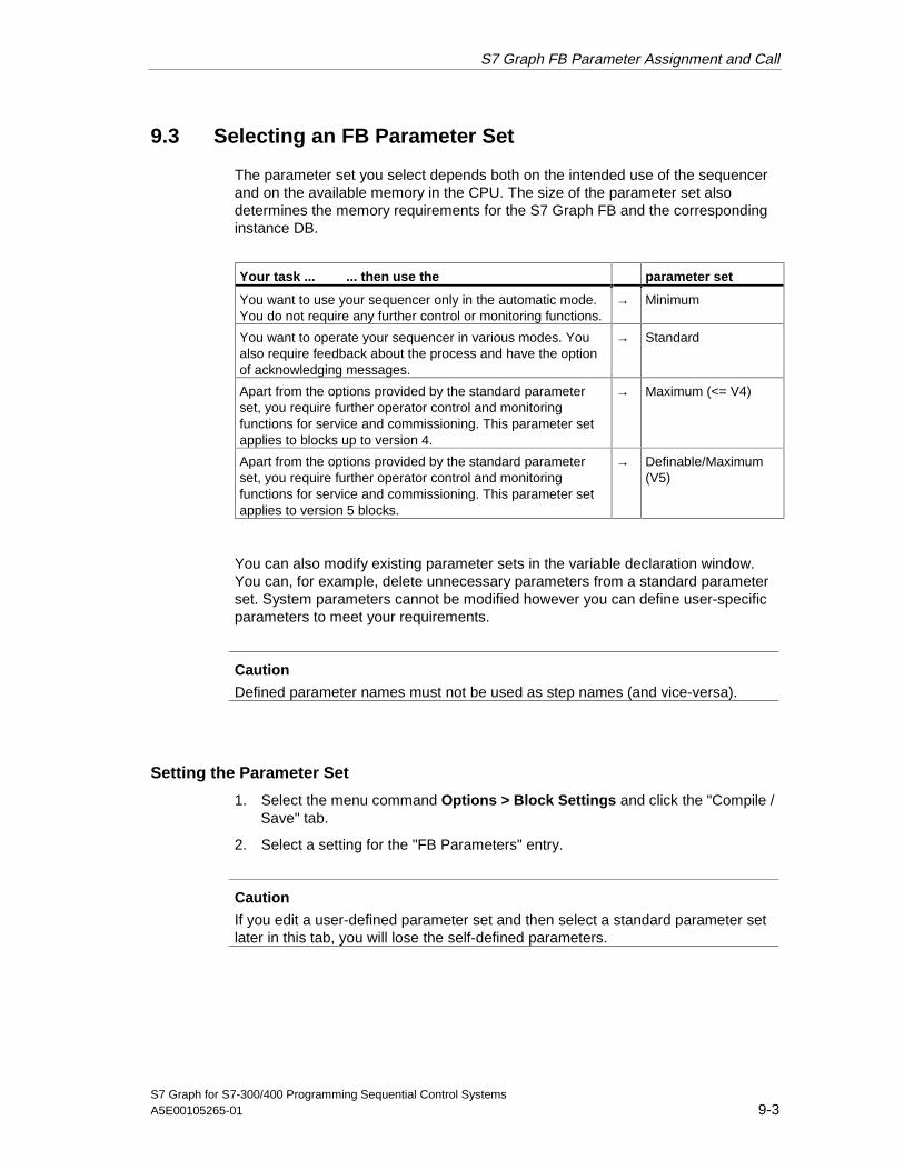
S7 Graph FB Parameter Assignment and Call
S7 Graph for S7-300/400 Programming Sequential Control SystemsA5E00105265-01 9-3
9.3 Selecting an FB Parameter Set
The parameter set you select depends both on the intended use of the sequencerand on the available memory in the CPU. The size of the parameter set alsodetermines the memory requirements for the S7 Graph FB and the correspondinginstance DB.
Your task ... ... then use the parameter set
You want to use your sequencer only in the automatic mode.You do not require any further control or monitoring functions.
→ Minimum
You want to operate your sequencer in various modes. Youalso require feedback about the process and have the optionof acknowledging messages.
→ Standard
Apart from the options provided by the standard parameterset, you require further operator control and monitoringfunctions for service and commissioning. This parameter setapplies to blocks up to version 4.
→ Maximum (<= V4)
Apart from the options provided by the standard parameterset, you require further operator control and monitoringfunctions for service and commissioning. This parameter setapplies to version 5 blocks.
→ Definable/Maximum(V5)
You can also modify existing parameter sets in the variable declaration window.You can, for example, delete unnecessary parameters from a standard parameterset. System parameters cannot be modified however you can define user-specificparameters to meet your requirements.
Caution
Defined parameter names must not be used as step names (and vice-versa).
Setting the Parameter Set
1. Select the menu command Options > Block Settings and click the "Compile /Save" tab.
2. Select a setting for the "FB Parameters" entry.
Caution
If you edit a user-defined parameter set and then select a standard parameter setlater in this tab, you will lose the self-defined parameters.
05.04.0105.04.200105.04.2001
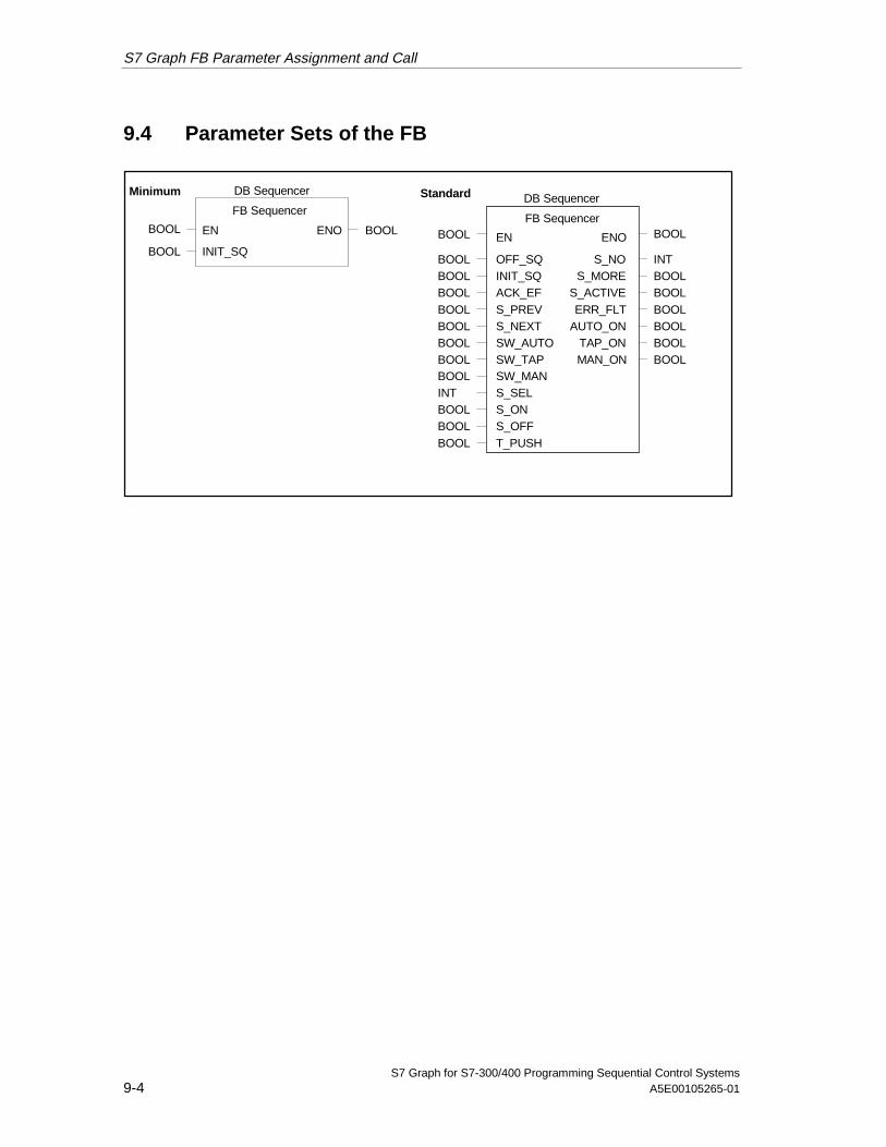
S7 Graph FB Parameter Assignment and Call
S7 Graph for S7-300/400 Programming Sequential Control Systems9-4 A5E00105265-01
9.4 Parameter Sets of the FB
FB Sequencer
BOOL INIT_SQ
EN ENO
DB Sequencer
BOOL BOOL
Minimum
FB Sequencer
BOOLBOOLBOOLBOOLBOOLBOOLBOOLBOOLINTBOOLBOOLBOOL
INTBOOLBOOLBOOLBOOLBOOLBOOL
S_NOS_MORE
S_ACTIVEERR_FLT
AUTO_ONTAP_ONMAN_ON
OFF_SQINIT_SQACK_EFS_PREVS_NEXTSW_AUTOSW_TAPSW_MAN
S_ONS_OFFT_PUSH
S_SEL
EN ENO
DB Sequencer
BOOLBOOL
Standard
05.04.0105.04.200105.04.2001
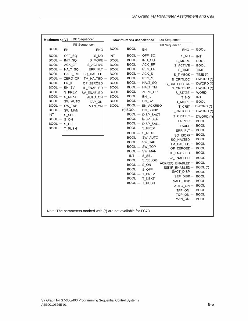
S7 Graph FB Parameter Assignment and Call
S7 Graph for S7-300/400 Programming Sequential Control SystemsA5E00105265-01 9-5
FB Sequencer
BOOLBOOLBOOLBOOLBOOLBOOLBOOLBOOLBOOLBOOLBOOLBOOL
INTBOOLBOOLBOOLBOOLBOOLBOOL
S_NOS_MORE
S_ACTIVEERR_FLT
AUTO_ONTAP_ON
MAN_ON
OFF_SQINIT_SQACK_EF
S_PREVS_NEXTSW_AUTOSW_TAPSW_MAN
S_ONS_OFFT_PUSH
S_SEL
EN ENO
DB Sequencer
BOOLBOOL
BOOLINTBOOLBOOLBOOL
HALT_SQ
ZERO_OPEN_ILEN_SV
HALT_TM
BOOLBOOLBOOLBOOLBOOL
SQ_HALTEDTM_HALTED
OP_ZEROEDIL_ENABLED
SV_ENABLED
Maximum <= V4 DB Sequencer
FB Sequencer
INTBOOLBOOLTIMETIME (*)
DWORD (*)
S_NO
S_MORES_ACTIVE
S_TIME
T_NOT_MORE
T_CRIT
ENO BOOL
DWORD (*)WORDINTBOOL
DWORD (*)
S_TIMEOK
S_CRITLOCS_CRITLOCERR
S_CRITSUPS_STATE
Maximum V5/ user-defined
T_CRITOLD DWORD (*)
SALL_DISP
BOOL (*)BOOLBOOLBOOLBOOLBOOL
SSKIP_ENABLEDSACT_DISP
SEF_DISP
BOOLBOOL
AUTO_ONTAP_ONTOP_ONMAN_ON
EN_ACKREQ
BOOLBOOLBOOLBOOLBOOLBOOLBOOLBOOLBOOLBOOLBOOLBOOL
OFF_SQINIT_SQACK_EF
ZERO_OPEN_ILEN_SV
EN_SSKIP
DISP_SEFDISP_SALLS_PREV
DISP_SACTL
ENBOOL
(*) BOOLBOOLBOOLBOOLBOOL
REG_EF
REG_SHALT_SQHALT_TM
ACK_S
BOOLBOOLBOOLBOOLBOOL
INTBOOLBOOLBOOLBOOLBOOLBOOL
S_NEXTSW_AUTOSW_TAP
S_OFFT_PREVT_NEXTT_PUSH
SW_TOP
S_SELS_SELOKS_ON
SW_MAN
ERR_FLT
DWORD (*)BOOLBOOLBOOLBOOLBOOL
T_CRITFLT
ERROR
FAULT
IL_ENABLED
SV_ENABLED
ACKREQ_ENABLED
BOOLBOOLBOOL
BOOL
BOOL
SQ_ISOFFSQ_HALTEDTM_HALTEDOP_ZEROED
Note: The parameters marked with (*) are not available for FC73
05.04.0105.04.200105.04.2001

S7 Graph FB Parameter Assignment and Call
S7 Graph for S7-300/400 Programming Sequential Control Systems9-6 A5E00105265-01
9.5 Input Parameters of the S7 Graph FB
The FB reacts to the rising edge of the input parameter (exception EN).
Parameter DataType
Description Min. Std. Max. User-def.
EN BOOL Controls execution of the FB (enable input). IfEN is not connected, the FB is alwaysexecuted.
á á á á
OFF_SQ BOOL OFF_SEQUENCE:Sequencer off, in other words deactivate allsteps
á á á
INIT_SQ BOOL INIT_SEQUENCE:Activate initial steps (reset sequencer)
á á á á
ACK_EF BOOL ACKNOWLEDGE_ERROR_FAULT:Acknowledgment of a disturbance, forceswitching to next step
á á á
REG_EF BOOL REGISTRATE_ERROR_FAULT:Register all errors and disturbances
á
ACK_S BOOL ACKNOWLEDGE_STEP:Acknowledge step indicated in S_NO
á
REG_S BOOL REGISTRATE_STEP:Register step indicated in S_NO
á
HALT_SQ BOOL HALT_SEQUENCE:Stop/reactivate sequencer
á á
HALT_TM BOOL HALT_TIMES:Stop/reactivate all step activation times andtime-dependent instructions (L and D) of thesequencer
á á
ZERO_OP BOOL ZERO_OPERANDS:Reset all addresses of the instructions N, D, Lin active steps to zero and do not executeCALL instructions in actions/reactivateaddresses and CALL instructions.
á á
EN_IL BOOL ENABLE_INTERLOCKS:Deactivate/reactivate interlocks (the sequencerbehaves as if interlocks were satisfied)
á á
EN_SV BOOL ENABLE_SUPERVISIONS:Deactivate/reactivate supervision conditions(the sequencer behaves as if supervisionconditions were not satisfied)
á á
EN_ACKREQ BOOL ENABLE_ACKNOWLEDGE_REQUIRED:Activate mandatory acknowledgment
á
DISP_SACT BOOL DISPLAY_ACTIVE_STEPS:Display active steps only
á
DISP_SEF BOOL DISPLAY_STEPS_WITH_ERROR_OR_FAULT:Display steps with errors and disturbed stepsonly
á
DISP_SALL BOOL DISPLAY_ALL_STEPS:Display all steps
á
05.04.0105.04.200105.04.2001
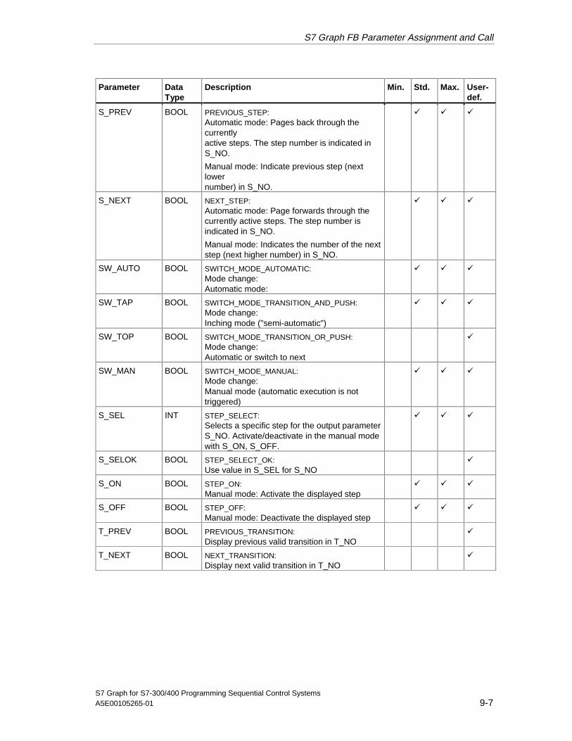
S7 Graph FB Parameter Assignment and Call
S7 Graph for S7-300/400 Programming Sequential Control SystemsA5E00105265-01 9-7
Parameter DataType
Description Min. Std. Max. User-def.
S_PREV BOOL PREVIOUS_STEP:Automatic mode: Pages back through thecurrentlyactive steps. The step number is indicated inS_NO.
Manual mode: Indicate previous step (nextlowernumber) in S_NO.
á á á
S_NEXT BOOL NEXT_STEP:Automatic mode: Page forwards through thecurrently active steps. The step number isindicated in S_NO.
Manual mode: Indicates the number of the nextstep (next higher number) in S_NO.
á á á
SW_AUTO BOOL SWITCH_MODE_AUTOMATIC:Mode change:Automatic mode:
á á á
SW_TAP BOOL SWITCH_MODE_TRANSITION_AND_PUSH:Mode change:Inching mode ("semi-automatic")
á á á
SW_TOP BOOL SWITCH_MODE_TRANSITION_OR_PUSH:Mode change:Automatic or switch to next
á
SW_MAN BOOL SWITCH_MODE_MANUAL:Mode change:Manual mode (automatic execution is nottriggered)
á á á
S_SEL INT STEP_SELECT:Selects a specific step for the output parameterS_NO. Activate/deactivate in the manual modewith S_ON, S_OFF.
á á á
S_SELOK BOOL STEP_SELECT_OK:Use value in S_SEL for S_NO
á
S_ON BOOL STEP_ON:Manual mode: Activate the displayed step
á á á
S_OFF BOOL STEP_OFF:Manual mode: Deactivate the displayed step
á á á
T_PREV BOOL PREVIOUS_TRANSITION:Display previous valid transition in T_NO
á
T_NEXT BOOL NEXT_TRANSITION:Display next valid transition in T_NO
á
05.04.0105.04.200105.04.2001

S7 Graph FB Parameter Assignment and Call
S7 Graph for S7-300/400 Programming Sequential Control Systems9-8 A5E00105265-01
Parameter DataType
Description Min. Std. Max. User-def.
T_PUSH BOOL PUSH_TRANSITION:Transition passes control when the condition issatisfiedand T_PUSH (edge)
Requirement: Inching (SW_TAP) or automaticor step –by-step (SW_TOP) mode
If the block is Version V4 (or earlier), the firstvalid transition switches. If the block is VersionV5 and if the input parameter T_NO isspecified, the transition whose number isdisplayed switches.Otherwise, the first valid transition switches.
á á á
EN_SSKIP BOOL ENABLE_STEP _SKIPPING:Activate skip step
á
Parameter set: Min. = Minimum; Std. = Standard; Max. = Maximum; User-def. User-defined
05.04.0105.04.200105.04.2001
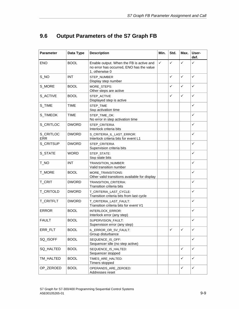
S7 Graph FB Parameter Assignment and Call
S7 Graph for S7-300/400 Programming Sequential Control SystemsA5E00105265-01 9-9
9.6 Output Parameters of the S7 Graph FB
Parameter Data Type Description Min. Std. Max. User-def.
ENO BOOL Enable output. When the FB is active andno error has occurred, ENO has the value1, otherwise 0
á á á á
S_NO INT STEP_NUMBERDisplay step number
á á á
S_MORE BOOL MORE_STEPS:Other steps are active
á á á
S_ACTIVE BOOL STEP_ACTIVEDisplayed step is active
á á á
S_TIME TIME STEP_TIMEStep activation time
á
S_TIMEOK TIME STEP_TIME_OK:No error in step activation time
á
S_CRITLOC DWORD STEP_CRITERIAInterlock criteria bits
á
S_CRITLOCERR
DWORD S_CRITERIA_IL_LAST_ERROR:Interlock criteria bits for event L1
á
S_CRITSUP DWORD STEP_CRITERIASupervision criteria bits
á
S_STATE WORD STEP_STATE:Step state bits
á
T_NO INT TRANSITION_NUMBER:Valid transition number
á
T_MORE BOOL MORE_TRANSITIONS:Other valid transitions available for display
á
T_CRIT DWORD TRANSITION_CRITERIA:Transition criteria bits
á
T_CRITOLD DWORD T_CRITERIA_LAST_CYCLE:Transition criteria bits from last cycle
á
T_CRITFLT DWORD T_CRITERIA_LAST_FAULT:Transition criteria bits for event V1
á
ERROR BOOL INTERLOCK_ERROR:Interlock error (any step)
á
FAULT BOOL SUPERVISION_FAULT:Supervision error (any step)
á
ERR_FLT BOOL IL_ERROR_OR_SV_FAULT:Group disturbance
á á á
SQ_ISOFF BOOL SEQUENCE_IS_OFF:Sequencer idle (no step active)
á
SQ_HALTED BOOL SEQUENCE_IS_HALTED:Sequencer stopped
á á
TM_HALTED BOOL TIMES_ARE_HALTED:Timers stopped
á á
OP_ZEROED BOOL OPERANDS_ARE_ZEROED:Addresses reset
á á
05.04.0105.04.200105.04.2001

S7 Graph FB Parameter Assignment and Call
S7 Graph for S7-300/400 Programming Sequential Control Systems9-10 A5E00105265-01
Parameter Data Type Description Min. Std. Max. User-def.
IL_ENABLED BOOL INTERLOCK_IS_ENABLED:Interlock enabled
á á
SV_ENABLED BOOL SUPERVISION_IS_ENABLED:Supervision enabled
á á
ACKREQ_ENABLED
BOOL ACKNOWLEDGE_REQUIRED_IS_ENABLED:Mandatory acknowledgment activated
á
SSKIP_ENABLED
BOOL STEP_SKIPPING_IS_ENABLED:Skip step activated
á
SACT_DISP BOOL ACTIVE_STEPS _WERE_DISPLAYED:Display active steps only in S_NO
á
SEF_DISP BOOL STEPS_WITH_ERROR_FAULT_WERE_DISPLAYED:Display only steps with error and disturbedsteps in S_NO
á
SALL_DISP BOOL ALL_STEPS_WERE_DISPLAYED:Display all steps in S_NO
á
AUTO_ON BOOL AUTOMATIC_IS_ON:Indicates the automatic mode
á á á
TAP_ON BOOL T_AND_PUSH_IS_ON:Indicates the inching mode
á á á
TOP_ON BOOL T_OR_PUSH_IS_ON:Display SW_TOP mode
á
MAN_ON BOOL MANUAL_IS_ON:Indicates the manual mode
á á á
Parameter set: Min. = Minimum; Std. = Standard; Max. = Maximum; User-def. = User-defined
9.7 The Modes of the Sequential Control System
By selecting one of the four possible modes, you decide how the sequencerprogresses from step to step. By setting suitable parameters for the S7 Graph FB,you can select the mode of the sequential control system as required. Thefollowing modes are available:
• Automatic Mode:In the automatic mode control passes to the next step when a transition issatisfied.
• Manual mode:In contrast to the automatic mode, in the manual mode, the next step in notenabled when the transition is satisfied. The steps are selected and deselectedmanually.
• Inching mode:The inching mode corresponds to the automatic mode with an additional stepenabling condition. Not only must the transition be satisfied, but there mustalso be a rising edge at the T_PUSH parameter before control passes to thenext step.
05.04.0105.04.200105.04.2001

S7 Graph FB Parameter Assignment and Call
S7 Graph for S7-300/400 Programming Sequential Control SystemsA5E00105265-01 9-11
• Automatic or switch to nextIn the "automatic or step-by-step" mode, control is passed to the next stepwhen the transition is satisfied or when there is a rising edge at the T_PUSHparameter.
Requirements for Operation in Different Modes
Automatic mode is the standard mode for sequencers. It is the default for allparameter sets of the S7 Graph FB.
To be able to select a different mode, you must compile the S7 Graph FB with thestandard, maximum or definable parameter set.
Selecting Modes
You select one of the four modes using the input parameters of the FB. Apply arising edge to one of the following parameters to activate the corresponding mode.
• SW_AUTO (Automatic Mode)
• SW_MAN (Manual Mode)
• SW_TAP (Inching Mode)
• SW_TOP (Automatic or Switch to next)
9.7.1 Automatic Mode (SW_AUTO)
In the automatic mode control passes to the next step when the transition issatisfied.
Input Parameters for the Automatic Mode
Parameters not listed are not mode-dependent.
Parameter Data Description
OFF_SQ BOOL Sequencer off; in other words, deactivate all stepsINIT_SQ BOOL Initialize sequencer, jump to initial stepACK_EF BOOL Acknowledgment of a disturbance, force switching to next stepS_PREV BOOL Pages back through the currently active steps. The step number is
indicated in S_NO.S_NEXT BOOL Page forwards through the currently active steps. The step number
is indicated in S_NO.SW_TAP BOOL Request inching modeSW_MAN BOOL Request manual modeSW_TOP BOOL Set automatic or switch to next mode
05.04.0105.04.200105.04.2001

S7 Graph FB Parameter Assignment and Call
S7 Graph for S7-300/400 Programming Sequential Control Systems9-12 A5E00105265-01
Output Parameters of the Automatic Mode
Parameter Data Description
S_NO INT Displays the active step selected with S_PREV or S_NEXT
S_MORE BOOL Further active steps exist and can be indicated in S_NO
S_ACTIVE BOOL The step indicated in S_NO is active
ERR_FLT BOOL Error/disturbance occurred
AUTO_ON BOOL Automatic mode is active
TAP_ON BOOL Inching mode is not active
MAN_ON BOOL Manual mode is not active
TOP_ON BOOL Automatic or switch to next mode is not activated
9.7.2 Manual mode (SW_MAN)
The manual mode is selected, for example, to test the sequencer. The manualmode is characterized as follows:
1. Next step not enabled when a transition is satisfied
2. Steps can be manually selected and deselected
Input Parameters of the Manual Mode
Parameters not listed are not mode-dependent.
Parameter Data Description
OFF_SQ BOOL All steps are immediately deactivated, in other words"Sequencer Off"
INIT_SQ BOOL Initialize sequencer, jump to initial step
ACK_EF BOOL Acknowledgment of a disturbance
S_PREV BOOL Indicate previous step in S_NO
S_NEXT BOOL Indicate next step in S_NO
SW_AUTO BOOL Request the automatic mode
SW_TAP BOOL Request inching mode
SW_TOP BOOL Set automatic or switch to next mode
S_SEL INT Step number for step selection, indicated in S_NO followingselection
S_ON BOOL The step indicated in S_NO is activated
S_OFF BOOL The step indicated in S_NO is deactivated
05.04.0105.04.200105.04.2001

S7 Graph FB Parameter Assignment and Call
S7 Graph for S7-300/400 Programming Sequential Control SystemsA5E00105265-01 9-13
Output Parameters of the Manual Mode
Parameter Data Description
S_NO INT Step number, indicates the selected step
S_MORE BOOL Other steps exist and can be indicated in S_NO.
S_ACTIVE BOOL The step indicated in S_NO is active
ERR_FLT BOOL Error/disturbance occurred
AUTO_ON BOOL The automatic mode is not active
TAP_ON BOOL Inching mode is not active
MAN_ON BOOL The manual mode is active
TOP_ON BOOL Automatic or switch to next mode is not activated
Caution
The input parameters DISP_SACT, DISP_SEF, DISP_SALL influence the numberof steps displayed at the S_NO parameter.
In the manual mode, an unsuitable parameter assignment can mean that no stepis displayed.
If you want to display all the steps, set the DISP_SALL parameter to TRUE ordelete the three input parameters DISP_SACT, DISP_SEF, DISP_SALL.
9.7.3 Inching mode (SW_TAP)
To install or test a system step by step, the inching mode can be very useful:
• The sequencer passes control when the transition is satisfied and there is anedge change from 0 to 1 at the parameter T_PUSH.
Input Parameters of the Inching Mode
Parameters not listed are not mode-dependent.
Parameter Data Description
OFF_SQ BOOL All steps are immediately deactivated, in other words"Sequencer Off"
INIT_SQ BOOL Initialize sequencer, jump to initial stepACK_EF BOOL Acknowledgment of a disturbanceS_PREV BOOL As for automaticS_NEXT BOOL As for automaticSW_AUTO BOOL Request the automatic modeSW_MAN BOOL Request manual modeSW_TOP BOOL Set automatic or switch to next modeT_PUSH BOOL The transition passes control when its conditions are satisfied
and there is a rising edge at T_PUSH.
05.04.0105.04.200105.04.2001

S7 Graph FB Parameter Assignment and Call
S7 Graph for S7-300/400 Programming Sequential Control Systems9-14 A5E00105265-01
Output Parameters of the Inching Mode
Parameter Data Description
S_NO INT Step number, indicates the selected step
S_MORE BOOL Further active steps exist and can be indicated in S_NO
S_ACTIVE BOOL The indicated step is active
ERR_FLT BOOL Error/disturbance occurred
AUTO_ON BOOL The automatic mode is not active
TAP_ON BOOL The inching mode is active
MAN_ON BOOL Manual mode is not active
TOP_ON BOOL Automatic or switch to next mode is not activated
9.7.4 Automatic or Switch to Next Mode (SW_TOP)
For initial project start up or for testing a control system step-by-step, the"automatic or switch to next" mode can be extremely useful:
• The sequencer progresses when the Transition is satisfied or when there is anedge change from 0 to 1 at the parameter T_PUSH.
Input Parameters of the Automatic or Switch to next Mode
Parameters not listed are not mode-dependent.
Parameter Data Description
OFF_SQ BOOL All steps are immediately deactivated, in other words"Sequencer Off"
INIT_SQ BOOL Initialize sequencer, jump to initial step
ACK_EF BOOL Acknowledgment of a disturbance
S_PREV BOOL As for automatic
S_NEXT BOOL As for automatic
SW_AUTO BOOL Request the automatic mode
SW_MAN BOOL Request manual mode
SW_TAP BOOL Request inching mode
T_PUSH BOOL The transition passes control when there is a rising edge atT_PUSH regardless of whether the transition is satisfied.
05.04.0105.04.200105.04.2001

S7 Graph FB Parameter Assignment and Call
S7 Graph for S7-300/400 Programming Sequential Control SystemsA5E00105265-01 9-15
Output Parameters of the Automatic or Switch to Next Mode
Parameter Data Description
S_NO INT Step number, indicates the selected step
S_MORE BOOL Further active steps exist and can be indicated in S_NO
S_ACTIVE BOOL The indicated step is active
ERR_FLT BOOL Error/disturbance occurred
AUTO_ON BOOL The automatic mode is not active
TAP_ON BOOL Inching mode is not active
MAN_ON BOOL Manual mode is not active
TOP_ON BOOL Automatic or switch to next mode is activated
9.7.5 Selecting a Step with S_SEL
1. Set the manual mode using the input parameter SW_MAN (edge change from0 to 1).
2. Enter the number of the step you want to select using the input parameterS_SEL. If the S_SELOK parameter exists in the compilation model, you mustconfirm the adoption of the step number with the parameter. The step is thenincluded in the display.
3. Activate the selected step with the input parameter S_ON (edge change from 0to 1).
If the sequencer has paths in simultaneous branches and you want to select morethan one step, repeat steps 2. and 3.
9.7.6 Selecting a Step with S_PREV or S_NEXT
1. Depending on whether you want to page forwards or backwards,
- select a previous step (lower step number) with the input parameterS_PREV,
- select a later step (higher step number) with the input parameter S_NEXT.
2. Activate the selected step with the input parameter S_ON (edge change from 0to 1).
Note
Remember that this procedure can lead to somewhat longer reaction times.
05.04.0105.04.200105.04.2001
S7 Graph FB Parameter Assignment and Call
S7 Graph for S7-300/400 Programming Sequential Control Systems9-16 A5E00105265-01
9.7.7 Progressing to the next Step with T_PUSH
1. Set the inching mode using the input parameter SW_TAP or the automatic orstep-by-step mode using the input parameter SW_TOP.
2. Apply an edge to the T_PUSH input parameter so that the transition switches.If you have set the SW_TAP parameter, the sequencer only progresses whenthe transition is satisfied. If you have set SW_TOP, the sequencer progresseseven if the transition is not satisfied.
Caution
• If the block is Version V4 (or earlier), the first valid transition switches.
• If the block is Version V5 and if the input parameter T_NO is specified, thetransition whose number is displayed switches. If there is no T_NO inputparameter, the first valid transition switches.
05.04.0105.04.200105.04.2001
S7 Graph for S7-300/400 Programming Sequential Control SystemsA5E00105265-01 10-1
10 Downloading the S7 Graph-FB andInstance-DB
10.1 Downloading Blocks from the Programming Device tothe CPU
Requirements for Downloading the S7 Graph FB to the CPU
To download the user program to the CPU, the following requirements must bemet:
• There is a connection between the programming device and the programmablelogic controller.
• The sequential control system consisting of the FB, instance DB and, forexample, OB1 has been created.
- The S7 Graph FB was compiled free of errors.
- The instance DB for the S7 Graph FB has been created.
• Whenever possible, download the S7 Graph block in the STOP mode sincefollowing downloading of the instance DB, the sequencer is automatically set tothe initial state.
• The S7 Graph FB is called in a block (for example OB1) that is executedcyclically, and the block has already been downloaded to the CPU.
Download with instance DB:
If you select the option "Include Instance DB" in the "General" tab selected with themenu command Options > Application Settings , S7 Graph checks whether theinstance DB has changed since it was last downloaded and whether it must beupdated. The option "Download with instance DB" is selected when necessary inthe "Download" dialog box. The instance DB must only be downloaded along withthe FB to the CPU in this situation.
Otherwise, S7 Graph does not check the loaded instance DB and leaves you todecide whether or not to transfer the instance DB again. The option "Downloadwith Instance DB" is not selected in the "Download" dialog box.
05.04.0105.04.200105.04.2001
Downloading the S7 Graph-FB and Instance-DB
S7 Graph for S7-300/400 Programming Sequential Control Systems10-2 A5E00105265-01
Download with Standard FC
If you select this option with the Options > Block Settings menu command in the"Compile / Save" tab, the system checks whether the specified standard FCalready exists online on the CPU. If the FC does not exist, it is made available fordownloading.
Turn off the sequencer before download
If this option is selected, the active structure element of the sequencer, the activetransition or the active step is stopped when you download the program to theCPU.
If the instance DB is downloaded as well, the function block starts at theinitialization step.
If the instance DB is not downloaded as well, the structural element active beforethe download is activated again on completion of the download.
Downloading to the CPU
To download the S7 Graph FB with its instance DB to the CPU, follow the stepsoutlined below:
1. With the FB open, click the menu command PLC > Download. The FBcurrently open in the working window is downloaded to the CPU.
2. Make the relevant entries and selections in the "Download" dialog box:
- If you have clicked "Include instance DB", the system automaticallyprepares the values according to the actual situation. You can change thisdefault.
- If you have not clicked "Include instance DB", you yourself must decidewhether or not the instance DB is downloaded as well.
- If the FB requires a standard FC, you can specify whether or not this FC isdownloaded as well. If the FC already exists online, this option isdeactivated.
3. If the blocks already exist on the CPU, confirm the prompt to overwrite theblocks.
Caution
You should only download S7 Graph blocks in the RUN mode when thesequencer is in the initial state or in the OFF state. If you download the blocks thesequencer in a different state, when overwriting an old block, problems may occurin the synchronization of the sequencer with the process. For example, bothlatching and non-latching actions of the steps active at the time of downloadingare not reset.
If it is not possible to change the sequencer to the initial state or to the OFF state,deactivate all steps (for example using the "Control Sequencer" function) beforeyou download the blocks to the CPU.
05.04.0105.04.200105.04.2001
Downloading the S7 Graph-FB and Instance-DB
S7 Graph for S7-300/400 Programming Sequential Control SystemsA5E00105265-01 10-3
10.2 Uploading Blocks from the CPU to the ProgrammingDevice
Requirements for Uploading Blocks to the Programming Device
To upload an FB from the CPU, there must be a connection between theprogramming device and the programmable controller.
Uploading from the CPU to the Programming Device
It is possible to upload blocks from the CPU using the SIMATIC Manager ofSTEP 7. The SIMATIC Manager decompiles the blocks to S7 Graph. You can thenedit the sequential control system as described in Section 5. For more informationabout uploading from the CPU to the programming device, refer to the online helpof the SIMATIC Manager.
Remember that you can only decompile again to a PG that does not contain theproject structure if you click the option "Interface Description - Download to PLC" inthe "Compile/Save" tab of the "Block Settings" dialog box.
05.04.0105.04.200105.04.2001

Downloading the S7 Graph-FB and Instance-DB
S7 Graph for S7-300/400 Programming Sequential Control Systems10-4 A5E00105265-01
05.04.0105.04.200105.04.2001

S7 Graph for S7-300/400 Programming Sequential Control SystemsA5E00105265-01 11-1
11 Monitoring and Testing the SequentialControl System
Using the Monitoring and Test Functions
The monitoring functions allow you to monitor and check a program while it is beingexecuted on the CPU.
This allows you to locate errors that were not indicated by the formal consistencycheck while you were writing the program or by the syntax check performed duringcompilation. These errors include the following:
• Programming errors, for example incorrectly set monitoring times in thesupervision conditions
• Logical errors in the program structure, in other words the program steps andconditions do not match the actual process sequence you require.
Methods of Testing the Sequential Control System
S7 Graph provides you with a variety of methods with which you can test asequential control system. These methods can be divided into the followingclasses:
• Monitoring the status information of the sequential control systemWith this function, you obtain a fast overview of the way in which thesequencers function.
• Controlling the sequencerApart from controlling the sequencer using the programmed FB call, S7 Graphalso provides a convenient dialog for the test mode.
• SynchronizationSynchronization is an S7 Graph function with which the sequencer can bematched to the process.
• Extended test functions for monitoring the sequential control systemBy calling STEP 7 functions from within S7 Graph, you can obtain further,comprehensive information about the entire process.
05.04.0105.04.200105.04.2001

Monitoring and Testing the Sequential Control System
S7 Graph for S7-300/400 Programming Sequential Control Systems11-2 A5E00105265-01
Requirements for Activating the Test Functions of S7 Graph
Before you can test an S7 Graph program, the following requirements must be met:
1. The PG must be connected online to the CPU.
2. The program was compiled without errors.
3. The S7 Graph FB must be called in a block that is executed cyclically (forexample OB1).
4. The program (in other words FB, DB OB and, if applicable, standard FCs) mustbe loaded on the CPU.
5. The CPU must be in the RUN (read) mode or RUN-P (read and write) mode.
11.1 Monitoring and Test Functions in the S7 Graph
11.1.1 Monitoring the Status Information
Principle of the S7 Graph Monitoring Function
When you start the monitoring function, you also start the test mode for checkingthe sequential control system. The individual steps and conditions and the signalstate of the addresses are displayed in different colors on the screen depending onthe status. The step-by-step execution of the program can therefore be followedvisually on the screen.
Depending on the current state of the sequencer, the status is displayed for thefollowing components:
• Steps and conditions
• Signal state of the addresses
Changing the Color Settings for the Status Display
You can select and set the required color for a particular status display individuallyusing the menu command Options > Application Settings in the "Editor" tab ofthe "Application Settings" dialog box.
05.04.0105.04.200105.04.2001

Monitoring and Testing the Sequential Control System
S7 Graph for S7-300/400 Programming Sequential Control SystemsA5E00105265-01 11-3
Status Display for Steps and Conditions
The status of the following elements of the sequencer is shown in color:
• Steps: Active and disturbed steps are shown in different colors.
• Permanent conditions, transitions, interlocks and supervisions:
- The display indicates whether individual conditions are satisfied (forexample a memory bit or an output).
- The display indicates whether a complete logic operation consisting ofseveral conditions is satisfied, for example an OR operation.
- The display indicates whether the entire transition (T), interlock (C) orsupervision (V) is satisfied.
Cond.1 Cond.2
The transition is satisfied and switchesCond.1 Cond.2
The transition is not satisfied and does not
satisfied Not satisfied
satisfiedsatisfied
Status Display for the Signal State of Addresses
In steps, the signal states of the programmed actions are displayed. The signalstate of the addresses (for example inputs, outputs, memory bits) is determined bythe actual query of the individual action. This means it is not purely a step-specificevaluation. Boolean addresses are displayed in this status display. The statusvalues of other addresses are displayed in the details window in the "Addresses"tab.
If there are block calls within the actions, there is no status display.
N
S1 S
A 4.2
A 4.3
S4
S0 R A 4.4
Step is active
Sequence of execution
Signal state
1
1
0
05.04.0105.04.200105.04.2001
Monitoring and Testing the Sequential Control System
S7 Graph for S7-300/400 Programming Sequential Control Systems11-4 A5E00105265-01
11.1.2 Control Sequencer
Control Sequencer is a test function with which you can test the sequencer withS7 Graph in all modes. All the settings and entries for the dialog box have thesame effect as the corresponding FB parameters.
The entries in the "Sequencer Control" dialog box can be different from the settingsyou used to compile the sequencers. The dialog box settings have priority.
"Sequencer Control" Dialog Box
The "Sequencer Control" dialog box is used both as an output field that displaysthe current settings and at the same time as an input field in which you can changethe current statusGlossStatus.
If you acknowledge an error, initialize the sequencer or want to change a step inthe manual mode, call the "Control Sequencer" dialog box with the menu commandDebug > Control Sequencer.
If you modify these settings in the dialog box, the originally selected settings areindicated in bold face so that you can return to the original setting at any time.
To be able to make modifications, the mode selector on the CPU must be set to theRUN-P position.
11.1.3 Synchronization
S7 Graph helps you to locate possible synchronization points between the processand sequencer.
A process is no longer synchronized when it is changed to a differentstatusGlossStatus manually. This can, for example, be the result when youchange to the manual mode in which you can activate any step even if the previoustransition is not satisfied. To be able to continue the process automatically and tolocate possible synchronization points, you can start the Synchronization function.S7 Graph indicates all steps that meet the following conditions:
The transition before the step is satisfied and the transition following the step is notsatisfied.
Requirements
• The sequencer is being controlled in the manual mode.
• The block is compiled with the option "Synchronization". You can find thisoption in the tab "Compile / Save" (menu command Options > Blocksettings).
05.04.0105.04.200105.04.2001

Monitoring and Testing the Sequential Control System
S7 Graph for S7-300/400 Programming Sequential Control SystemsA5E00105265-01 11-5
Starting Synchronization
To start synchronization:
1. Select the menu command Debug > Synchronization.S7 Graph now searches for all steps that meet the synchronization condition(transition before the step is satisfied and transition after the step is notsatisfied). All steps found are marked yellow.
2. Select one or more of these steps to be selected using the mouse pointer thatchanges to a crosshair. You can also select other steps that are not markedyellow.
Caution
In a simultaneous branch, each path must contain a step to be activated.
3. Activate the selected steps with the "Activate" button.
4. Now switch the sequencer back to the automatic mode.
11.2 Test Functions of STEP 7
The following test functions are available for further analysis of the sequentialcontrol system. Please note, however, that not all the functions available provideinformation about an S7 Graph sequential control system:
• Monitor and modify variables
• Query the module statusGlossStatus
• Query the operating mode
• Evaluate CPU messages
• Create reference data
• Create process diagnostic data
These functions provide you with further methods of debugging and supplyimportant information about the use of blocks and addresses. You can also selectthese test functions directly in the SIMATIC Manager.
Note
If you require more detailed information about these topics, display the help textsrelating to the menu commands in the SIMATIC Manager.
05.04.0105.04.200105.04.2001

Monitoring and Testing the Sequential Control System
S7 Graph for S7-300/400 Programming Sequential Control Systems11-6 A5E00105265-01
Monitoring and Modifying Variables
With the menu command PLC > Monitor/Modify Variables, you can create avariable table and monitor and modify the signal states of addresses (for exampleinput I2.3).
The signal states to be monitored can be put together individually in the variabletable by entering the required addresses in the displayed table.
Querying Module Information and the Operating Mode
With the menu command PLC > Module Information, you can obtain a variety ofinformation about modules. As additional information on the sequential controlsystem, the content of the diagnostic buffer and the current utilization of the workand load memory can be particularly interesting.
You can, for example, find out the reasons for errors using the "Diagnostic Buffer"and "Stacks" tabs.
With the menu command PLC > Operating Mode, you can query and modify thecurrent mode of your CPU, for example restart.
Evaluating the Diagnostic Buffer
If you have set the option "Message with WR_USMSG (SFC52)" with the menucommand Options > Block Settings in the "Messages" tab, S7 Graph enters thefollowing messages in the diagnostic buffer:
• Interlock errors entering/leaving state
• Monitoring errors (execution errors) entering/leaving state
From the detailed information about the message, you can found out where theerror occurred.
Details of event: 4 of 100 Event ID: 16#9162
Graph 7 interlock error entered state Step 3 FB Number 7, DB Number 9 Event entering state
Evaluating the CPU Messages
In the SIMATIC Manager, you can use the menu command PLC > S7 Message todisplay event and alarm messages.
05.04.0105.04.200105.04.2001

Monitoring and Testing the Sequential Control System
S7 Graph for S7-300/400 Programming Sequential Control SystemsA5E00105265-01 11-7
Displaying Reference Data
To test the sequential control system, you can call up a variety of reference data.You create the reference data as follows:
• When you save the FB, reference data are created if you have selected thisfunction in the "General" tab which you can display with the menu commandOptions > Application Settings. The "Generate Reference Data" option mustbe selected.
• With the menu command Options > Reference Data, the reference data arecreated when required. Following this, S7 Graph calls the STEP 7 dialog box todisplay the reference data.
The following table shows the information available:
List Content of the list
Cross-reference Overview of the use of addresses in the memory areas I, Q,M, P, T, C and DB within the user program.
Program structure Call hierarchy of the blocks within a user program andoverview of the blocksused and their interdependencies.
Reference list Shows the use of the following:
• Inputs, outputs and memory bits
• Timers and counters
List of unused addresses Overview of all the symbols found in the symbol table but notused in the partsof the user program for which reference data exist.
List of addresses withoutsymbols
Overview of all the absolute addresses that are used in partsof the user program for which reference data exist but forwhich there is no symbol defined in the symbol table.
If the reference data "Program Structure" or "Cross-Reference List" are displayed,you can jump to the point in the user program at which a selected block or addressis used with the menu command Edit > Go To > Location.
Generating Diagnostic Data
Diagnostic data are generated when you save the FB if you select the "GeneratePDIAG Data" option in the "General" tab of the "Application Settings" dialog box.You must also select the "Message with ALARM_SQ/ALARM_S" option in the"Messages" tab of the "Block Settings" dialog box.
05.04.0105.04.200105.04.2001

Monitoring and Testing the Sequential Control System
S7 Graph for S7-300/400 Programming Sequential Control Systems11-8 A5E00105265-01
Updating Diagnostic Data After Rewiring
If you have modified addresses in the SIMATIC manager using the menucommand Rewire, and the addresses are also used by the sequencer, thecorresponding diagnostic data are only updated when you open the correspondingS7 Graph FB again and save it.
05.04.0105.04.200105.04.2001

S7 Graph for S7-300/400 Programming Sequential Control SystemsA5E00105265-01 12-1
12 Printing the Sequencer
Documenting the Program
After you have created the sequential control system, you can print it out at anytime to create your documentation. The printout is either according to the settingsor the content of the active window is printed. The display level and zoom factor setfor the active window are taken into account in the printout.
You can modify the page layout to suit your purposes and check it in the printpreview. You can adapt the following:
• Display level and zoom factor
• Header and footer of the printed page
• Page format
Appearance of the Printout
If you have a multi-page printout, references to the adjacent pages are printed atthe margins of the pages to allow better orientation. References to previous andfollowing elements are also printed if, for example, consecutive steps or steps andtransitions are split on two pages due to a form feed.
To improve clarity, the start of a transition can be printed right-aligned and theaction block left-aligned. There is adequate clearance between sequencer paths.Pages with no content are not printed.
Requirements for Printing
The S7 Graph print function will already be familiar to you from other Windowsapplications. Before you can print, the printer must be installed and initialized usingthe Windows Control Panel.
Appearance of the Printout
In the "Print" dialog box, you can select the content of the current printout.
• Current View: The view of the FB as selected in the working area is transferredto the printer.
• According to Settings: Regardless of the current display, the settings you madein the "Print" tab of the "Application Settings" dialog box are used.
05.04.0105.04.200105.04.2001
Printing the Sequencer
S7 Graph for S7-300/400 Programming Sequential Control Systems12-2 A5E00105265-01
"Print" Tab, "Application Settings" Dialog Box
in the "Print" tab of the "Application Settings", you can specify the standardsettings for printouts. You select the required settings by placing a check mark.You can include the following components in the printout:
• Sequencer view with / without conditions and actions
• Step view with / without address List, step comment and cross references
• Permanent instructions with / without address list
• Addresses
• Block properties
• Compiler options
• Variables
The active block can also be displayed in symbolic / absolute format or as aLAD/FBD block.
Creating the Headers and Footers in the SIMATIC Manager
To specify the header and footer lines for your documents, use the menu commandFile > Headers and Footers in the SIMATIC manager.
Selecting the Page Format
With the menu command File > Page Setup, you can select the page format yourequire for your printout. The format set in the SIMATIC Manager is taken as thedefault.
Checking the Current Block in the Print Preview
With the menu command File > Print Preview, you can check all the settings forthe current block before you send the document to the printer. Editing is notpossible in this view.
Starting the Print Job
You can start the print function in two ways in S7 Graph:
• Select the "Print" button in the toolbar.
• Select the menu command File > Print.
A dialog box is then opened in which you can select various print options such asthe printer and number of copies.
Confirm with OK to send the document to the printer.
05.04.0105.04.200105.04.2001
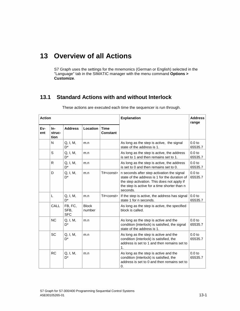
S7 Graph for S7-300/400 Programming Sequential Control SystemsA5E00105265-01 13-1
13 Overview of all Actions
S7 Graph uses the settings for the mnemonics (German or English) selected in the"Language" tab in the SIMATIC manager with the menu command Options >Customize.
13.1 Standard Actions with and without Interlock
These actions are executed each time the sequencer is run through.
Action
Ev-ent
In-struc-tion
Address Location TimeConstant
Explanation Addressrange
N Q, I, M,D∗
m.n As long as the step is active, the signalstate of the address is 1.
0.0 to65535.7
S Q, I, M,D∗
m.n As long as the step is active, the addressis set to 1 and then remains set to 1.
0.0 to65535.7
R Q, I, M,D∗
m.n As long as the step is active, the addressis set to 0 and then remains set to 0.
0.0 to65535.7
D Q, I, M,D∗
m.n T#<const> n seconds after step activation the signalstate of the address is 1 for the duration ofthe step activation. This does not apply ifthe step is active for a time shorter than nseconds.
0.0 to65535.7
L Q, I, M,D∗
m.n T#<const> If the step is active, the address has signalstate 1 for n seconds.
0.0 to65535.7
CALL FB, FC,SFB,SFC
Blocknumber
As long as the step is active, the specifiedblock is called.
NC Q, I, M,D∗
m.n As long as the step is active and thecondition (interlock) is satisfied, the signalstate of the address is 1.
0.0 to65535.7
SC Q, I, M,D∗
m.n As long as the step is active and thecondition (interlock) is satisfied, theaddress is set to 1 and then remains set to1.
0.0 to65535.7
RC Q, I, M,D∗
m.n As long as the step is active and thecondition (interlock) is satisfied, theaddress is set to 0 and then remains set to0.
0.0 to65535.7
05.04.0105.04.200105.04.2001

Overview of all Actions
S7 Graph for S7-300/400 Programming Sequential Control Systems13-2 A5E00105265-01
Action
Ev-ent
In-struc-tion
Address Location TimeConstant
Explanation Addressrange
DC Q, I, M,D∗
m.n T#<const> n seconds after step activation and as longas the step is active and the condition(interlock) is satisfied, the signal state ofthe address is 1. If the step is not active,the signal state of the address is 0.
0.0 to65535.7
LC Q, I, M,D∗
m.n T#<const> If the step is active and the condition(supervision) is satisfied, the address hasthe signal 1 for n seconds. If the step is notactive, the address has signal 0.
0.0 to65535.7
CALLC
FB, FC,SFB,SFC
Blocknumber
As long as the step is active and thecondition (interlock) is satisfied, thespecified block is called.
An instance DB is required with CALL[C] FB/SFB.
13.2 Event-Dependent Actions - with and without Interlock
These actions are executed once when the event occurs and the correspondingstep is active. When the sequencer is run through after this, an event-dependentaction is executed again only if the event reoccurs.
S1: Actions linked to a step becoming active
Action
Ev-ent
In-struc-tion
Address Location
Explanation Addressrange
S1 N Q, I, M, D∗ m.n As soon as the step becomes active (enters state),the signal state of the address is 1.
0.0 to65535.7
S1 S Q, I, M, D m.n As soon as the step becomes active (enters state),the address is set to 1 and then remains set to 1.
0.0 to65535.7
S1 R Q, I, M, D∗ m.n As soon as the step becomes active (enters state),the address is set to 0 and then remains set to 0.
0.0 to65535.7
S1 CALL FB, FC,SFB,SFC
Blocknumber
As soon as the step becomes active (enters state),the specified block is called.
S1 ON S I As soon as the step becomes active (enters state),step i is activated.
i = stepnumber
S1 OFF S I As soon as the step becomes active (enters state),step i is deactivated.
i = stepnumber
05.04.0105.04.200105.04.2001

Overview of all Actions
S7 Graph for S7-300/400 Programming Sequential Control SystemsA5E00105265-01 13-3
Action
Ev-ent
In-struc-tion
Address Location
Explanation Addressrange
S1 OFF S_ALL As soon as the step becomes active (enters state), allsteps are deactivated except for the step in which theaction is located.
S1 NC Q,I,M,D m.n As soon as the step becomes active (enters state)and the condition (interlock) is satisfied, the signalstate of the address is 1.
0.0 to65535.7
S1 SC Q, I, M, D∗ m.n As soon as the step becomes active (enters state)and the condition (interlock) is satisfied, the addressis set to 1 and then remains set to 1.
0.0 to65535.7
S1 RC Q, I, M, D∗ m.n As soon as the step becomes active (enters state)and the condition (interlock) is satisfied, the addressis set to 0 and then remains set to 0.
0.0 to65535.7
S1 CALLC
FB, FC,SFB,SFC
Blocknumber
As soon as the step becomes active and thecondition (interlock) is satisfied, the specified block iscalled.
S1 ONC S I As soon as the step becomes active (enters state)and the condition (interlock) is satisfied, step i isactivated.
i = stepnumber
S1 OFFC S I As soon as the step becomes active (enters state)and the condition (interlock) is satisfied, step i isdeactivated.
i = stepnumber
S1 OFFC S_ALL As soon as the step becomes active (enters state)and the condition (interlock) is satisfied, all steps aredeactivated except for the step in which the action islocated.
05.04.0105.04.200105.04.2001

Overview of all Actions
S7 Graph for S7-300/400 Programming Sequential Control Systems13-4 A5E00105265-01
S0: Actions linked to a step being deactivated
Action
Ev-ent
In-struc-tion
Address Location
Explanation Addressrange
S0 N Q, I, M, D∗ m.n As soon as the step is deactivated (leaves state), thesignal state of the address is 1.
0.0 to65535.7
S0 S Q, I, M, D∗ m.n As soon as the step is deactivated (leaves state), theaddress is set to 1 and then remains set to 1.
0.0 to65535.7
S0 R Q, I, M, D∗ m.n As soon as the step is deactivated (leaves state), theaddress is set to 0 and then remains set to 0.
0.0 to65535.7
S0 CALL FB, FC,SFB,SFC
Blocknumber
As soon as the step is deactivated (leaves state), thespecified block is called.
S0 ON S I As soon as the step is deactivated (leaves state),step i is activated.
i = stepnumber
S0 OFF S I As soon as the step is deactivated (leaves state),step i is also deactivated.
i = stepnumber
V1: Actions linked to supervision errors entering the state
Action
Ev-ent
In-struc-tion
Address Location
Explanation Addressrange
V1 N Q,I,M,D m.n As soon as a supervision error occurs while the stepis active or a supervision error had been detectedbefore the step became active, the signal state of theaddress is 1.
0.0 to65535.7
V1 S Q,I,M,D m.n As soon as a supervision error occurs while the stepis active or a supervision error had been detectedbefore the step became active, the address is set to 1and then remains set to 1.
0.0 to65535.7
V1 R Q,I,M,D m.n As soon as a supervision error occurs while the stepis active or a supervision error had been detectedbefore the step became active, the address is set to 0and then remains set to 0.
0.0 to65535.7
V1 CALL FB, FC,SFB,SFC
Blocknumber
As soon as a supervision error occurs while the stepis active or a supervision error had been detectedbefore the step became active, the specified block iscalled.
V1 ON S I As soon as a supervision error occurs while the stepis active or a supervision error had been detectedbefore the step became active, step i is activated.
0.0 to65535.7
V1 OFF S I As soon as a supervision error occurs while the stepis active or a supervision error had been detectedbefore the step became active, step i is deactivated.
0.0 to65535.7
05.04.0105.04.200105.04.2001
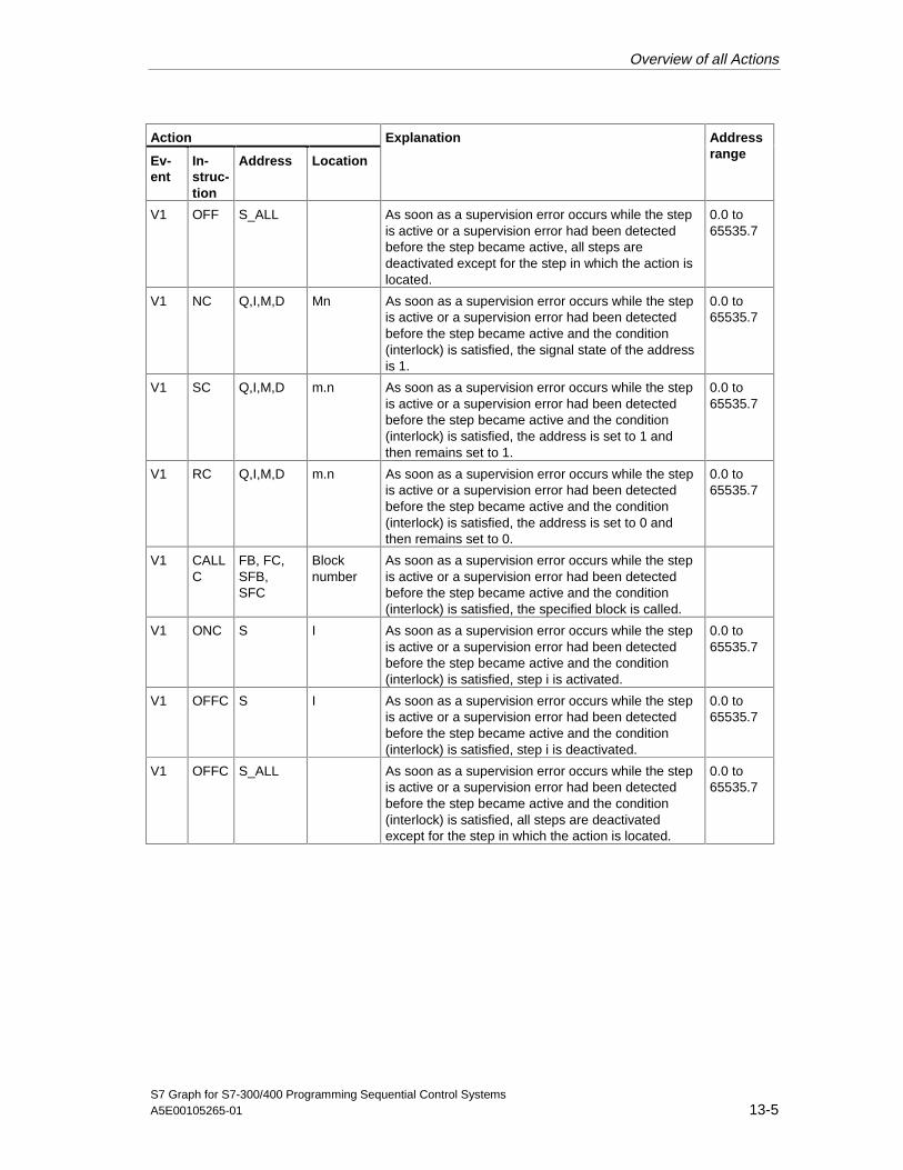
Overview of all Actions
S7 Graph for S7-300/400 Programming Sequential Control SystemsA5E00105265-01 13-5
Action
Ev-ent
In-struc-tion
Address Location
Explanation Addressrange
V1 OFF S_ALL As soon as a supervision error occurs while the stepis active or a supervision error had been detectedbefore the step became active, all steps aredeactivated except for the step in which the action islocated.
0.0 to65535.7
V1 NC Q,I,M,D Mn As soon as a supervision error occurs while the stepis active or a supervision error had been detectedbefore the step became active and the condition(interlock) is satisfied, the signal state of the addressis 1.
0.0 to65535.7
V1 SC Q,I,M,D m.n As soon as a supervision error occurs while the stepis active or a supervision error had been detectedbefore the step became active and the condition(interlock) is satisfied, the address is set to 1 andthen remains set to 1.
0.0 to65535.7
V1 RC Q,I,M,D m.n As soon as a supervision error occurs while the stepis active or a supervision error had been detectedbefore the step became active and the condition(interlock) is satisfied, the address is set to 0 andthen remains set to 0.
0.0 to65535.7
V1 CALLC
FB, FC,SFB,SFC
Blocknumber
As soon as a supervision error occurs while the stepis active or a supervision error had been detectedbefore the step became active and the condition(interlock) is satisfied, the specified block is called.
V1 ONC S I As soon as a supervision error occurs while the stepis active or a supervision error had been detectedbefore the step became active and the condition(interlock) is satisfied, step i is activated.
0.0 to65535.7
V1 OFFC S I As soon as a supervision error occurs while the stepis active or a supervision error had been detectedbefore the step became active and the condition(interlock) is satisfied, step i is deactivated.
0.0 to65535.7
V1 OFFC S_ALL As soon as a supervision error occurs while the stepis active or a supervision error had been detectedbefore the step became active and the condition(interlock) is satisfied, all steps are deactivatedexcept for the step in which the action is located.
0.0 to65535.7
05.04.0105.04.200105.04.2001

Overview of all Actions
S7 Graph for S7-300/400 Programming Sequential Control Systems13-6 A5E00105265-01
V0: Actions linked with supervision errors leaving the state
Action
Ev-ent
In-struc-tion
Address Location
Explanation Addressrange
V0 N Q,I,M,D m.n As soon as a supervision error leaves the state (iseliminated or acknowledged), the signal state of theaddress is 1.
0.0 to65535.7
V0 S Q,I,M,D m.n As soon as a supervision error leaves the state (iseliminated or acknowledged), the address is set to 1and then remains set to 1.
0.0 to65535.7
V0 R Q,I,M,D m.n As soon as a supervision error leaves the state (iseliminated or acknowledged), the address is set to 0and then remains set to 0.
0.0 to65535.7
V0 CALL FB,FC,SFB,SFC
V0 ON S I As soon as a supervision error leaves the state (iseliminated or acknowledged), step i is activated.
i = stepnumber
V0 OFF S I As soon as a supervision error leaves the state (iseliminated or acknowledged), step i is alsodeactivated.
i = stepnumber
L0: Actions linked with interlocks entering the state
Action
Ev-ent
In-struc-tion
Address Location
Explanation Addressrange
L0 N Q,I,M,D m.n As soon as the interlock condition is satisfied (entersstate) when the step is active, the signal state of theaddress is 1.
0.0 to65535.7
L0 S Q,I,M,D m.n As soon as the interlock condition is satisfied whenthe step is active (enters state), the address is set to1 and then remains set to 1.
0.0 to65535.7
L0 R Q,I,M,D m.n As soon as the interlock condition is satisfied whenthe step is active (enters state), the address is set to0 and then remains set to 0.
0.0 to65535.7
L0 CALL FB, FC,SFB,SFC
Blocknumber
As soon as the interlock condition is satisfied whenthe step is active (enters state), the specified block iscalled.
L0 ON S I As soon as the interlock condition is satisfied whenthe step is active (enters state), step i is activated.
i = stepnumber
L0 OFF S I As soon as the interlock condition is satisfied whenthe step is active (enters state), step i is deactivated.
i = stepnumber
05.04.0105.04.200105.04.2001

Overview of all Actions
S7 Graph for S7-300/400 Programming Sequential Control SystemsA5E00105265-01 13-7
L1: Actions linked with interlocks leaving state
Action
Ev-ent
In-struc-tion
Address Location
Explanation Addressrange
L1 N Q,I,M,D m.n As soon as the interlock condition is no longersatisfied (leaves state) while the step is active or ifthe interlock condition is not satisfied when the stepbecomes active, the signal state of the address is 1.
0.0 to65535.7
L1 S Q,I,M,D m.n As soon as the interlock condition is satisfied whenthe step is no longer satisfied (leaves state) while thestep is active or if the interlock condition is notsatisfied when the step becomes active, the addressis set to 1 and then remains set to 1.
0.0 to65535.7
L1 R Q,I,M,D
m.n
As soon as the interlock condition is satisfied whenthe step is no longer satisfied (leaves state) while thestep is active or if the interlock condition is notsatisfied when the step becomes active, the addressis set to 0 and then remains set to 0.
0.0 to65535.7
L1 CALL FB, FC,SFB,SFC
Blocknumber
As soon as the interlock condition is satisfied whenthe step is no longer satisfied (leaves state) while thestep is active or if the interlock condition is notsatisfied when the step becomes active, the specifiedblock is called.
L1 ON S I As soon as the interlock condition is satisfied whenthe step is no longer satisfied (leaves state) while thestep is active or if the interlock condition is notsatisfied when the step becomes active, step i isactivated.
i = stepnumber
L1 OFF S I As soon as the interlock condition is satisfied whenthe step is no longer satisfied (leaves state) while thestep is active or if the interlock condition is notsatisfied when the step becomes active, step i is alsodeactivated.
i = stepnumber
L1 OFF S_ALL As soon as the interlock condition is satisfied whenthe step is no longer satisfied (leaves state) while thestep is active or if the interlock condition is notsatisfied when the step becomes active, all steps aredeactivated except for the step in which the action islocated.
05.04.0105.04.200105.04.2001
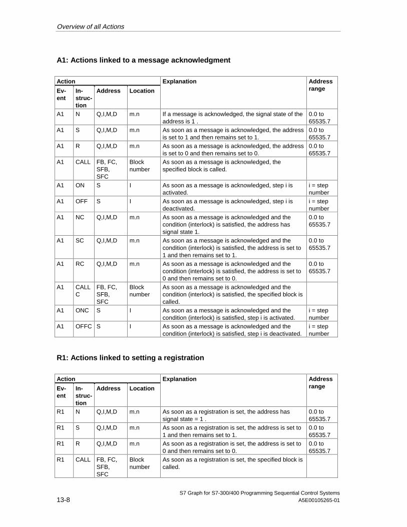
Overview of all Actions
S7 Graph for S7-300/400 Programming Sequential Control Systems13-8 A5E00105265-01
A1: Actions linked to a message acknowledgment
Action
Ev-ent
In-struc-tion
Address Location
Explanation Addressrange
A1 N Q,I,M,D m.n If a message is acknowledged, the signal state of theaddress is 1 .
0.0 to65535.7
A1 S Q,I,M,D m.n As soon as a message is acknowledged, the addressis set to 1 and then remains set to 1.
0.0 to65535.7
A1 R Q,I,M,D m.n As soon as a message is acknowledged, the addressis set to 0 and then remains set to 0.
0.0 to65535.7
A1 CALL FB, FC,SFB,SFC
Blocknumber
As soon as a message is acknowledged, thespecified block is called.
A1 ON S I As soon as a message is acknowledged, step i isactivated.
i = stepnumber
A1 OFF S I As soon as a message is acknowledged, step i isdeactivated.
i = stepnumber
A1 NC Q,I,M,D m.n As soon as a message is acknowledged and thecondition (interlock) is satisfied, the address hassignal state 1.
0.0 to65535.7
A1 SC Q,I,M,D m.n As soon as a message is acknowledged and thecondition (interlock) is satisfied, the address is set to1 and then remains set to 1.
0.0 to65535.7
A1 RC Q,I,M,D m.n As soon as a message is acknowledged and thecondition (interlock) is satisfied, the address is set to0 and then remains set to 0.
0.0 to65535.7
A1 CALLC
FB, FC,SFB,SFC
Blocknumber
As soon as a message is acknowledged and thecondition (interlock) is satisfied, the specified block iscalled.
A1 ONC S I As soon as a message is acknowledged and thecondition (interlock) is satisfied, step i is activated.
i = stepnumber
A1 OFFC S I As soon as a message is acknowledged and thecondition (interlock) is satisfied, step i is deactivated.
i = stepnumber
R1: Actions linked to setting a registration
Action
Ev-ent
In-struc-tion
Address Location
Explanation Addressrange
R1 N Q,I,M,D m.n As soon as a registration is set, the address hassignal state = 1 .
0.0 to65535.7
R1 S Q,I,M,D m.n As soon as a registration is set, the address is set to1 and then remains set to 1.
0.0 to65535.7
R1 R Q,I,M,D m.n As soon as a registration is set, the address is set to0 and then remains set to 0.
0.0 to65535.7
R1 CALL FB, FC,SFB,SFC
Blocknumber
As soon as a registration is set, the specified block iscalled.
05.04.0105.04.200105.04.2001

Overview of all Actions
S7 Graph for S7-300/400 Programming Sequential Control SystemsA5E00105265-01 13-9
Action
Ev-ent
In-struc-tion
Address Location
Explanation Addressrange
R1 ON S I As soon as a registration is set, step i is activated. i = stepnumber
R1 OFF S I As soon as a registration is set, step i is deactivated. i = stepnumber
R1 NC Q,I,M,D m.n As soon as a registration is set and the condition(interlock) is satisfied, the signal state of the addressis 1.
0.0 to65535.7
R1 SC Q,I,M,D m.n As soon as a registration is set and the condition(interlock) is satisfied, the address is set to 1 andthen remains set to 1.
0.0 to65535.7
R1 RC Q,I,M,D m.n As soon as a registration is set and the condition(interlock) is satisfied, the address is set to 0 andthen remains set to 0.
0.0 to65535.7
R1 CALLC
FB, FC,SFB,SFC
Blocknumber
As soon as a registration is set and the condition(interlock) is satisfied, the specified block is called.
R1 ONC S I As soon as a registration is set and the condition(interlock) is satisfied, step i is activated.
i = stepnumber
R1 OFFC S I As soon as a registration is set and the condition(interlock) is satisfied, step i is deactivated.
i = stepnumber
Address D: Format: DBi.DBXm.n (i = block number, m = byte address, n = bit address)
For CALL[C] FB/SFB, an instance DB is required.
05.04.0105.04.200105.04.2001

Overview of all Actions
S7 Graph for S7-300/400 Programming Sequential Control Systems13-10 A5E00105265-01
13.3 Counters in Actions
These actions are executed once when the event occurs and the correspondingstep is active. When the sequencer is run through after this, an event-dependentaction is executed again only if the event reoccurs.
S1: Counters in actions linked with activation of a step
Action
Ev-ent
In-struc-tion
Address Location
Explanation Addressrange
S1 CS C
<initialcountervalue>
X As soon as the step becomes active (enters state),the initial counter value is loaded in the counter.
x =counternumber
S1 CU C X As soon as the step becomes active (enters state),the counter is incremented by 1.
x =counternumber
S1 CD C X As soon as the step becomes active (enters state),the counter is decremented by 1.
x =counternumber
S1 CR C X As soon as the step becomes active (enters state),the counter is reset to 0.
x =counternumber
S1 CSC C
<initialcountervalue>
X As soon as the step becomes active (enters state)and the condition (interlock) is satisfied, the initialcounter value is loaded in the counter.
x =counternumber
S1 CUC C X As soon as the step becomes active (enters state)and the condition (interlock) is satisfied, the counteris incremented by 1.
x =counternumber
S1 CDC C X As soon as the step becomes active (enters state)and the condition (interlock) is satisfied, the counteris decremented by 1.
x =counternumber
S1 CRC C X As soon as the step becomes active (enters state)and the condition (interlock) is satisfied, the counteris reset to 0.
x =counternumber
05.04.0105.04.200105.04.2001

Overview of all Actions
S7 Graph for S7-300/400 Programming Sequential Control SystemsA5E00105265-01 13-11
S0: Counters in actions linked with deactivation of a step
Action
Ev-ent
In-struc-tion
Address Location
Explanation Addressrange
S0 CS C
<initialcountervalue>
X As soon as the step is deactivated (leaves state),the initial counter value is loaded in the counter.
x =counternumber
S0 CU C X As soon as the step is deactivated (leaves state),the counter is incremented by 1.
x =counternumber
S0 CD C X As soon as the step is deactivated (leaves state),the counter is decremented by 1.
x =counternumber
S0 CR C X As soon as the step is deactivated (leaves state),the counter is reset to 0.
x =counternumber
L1: Counters in actions linked with interlocks leaving state
Action
Ev-ent
In-struc-tion
Address Location
Explanation Addressrange
L1 CS C
<initialcountervalue>
X As soon as the interlock condition is no longersatisfied (leaves state) while the step is active or ifthe interlock condition is not satisfied when the stepbecomes active, the initial counter value is loadedin the counter.
x =counternumber
L1 CU C X As soon as the interlock condition is no longersatisfied (leaves state) while the step is active or ifthe interlock condition is not satisfied when the stepbecomes active, the counter is incremented by 1.
x =counternumber
L1 CD C X As soon as the interlock condition is no longersatisfied (leaves state) while the step is active or ifthe interlock condition is not satisfied when the stepbecomes active, the counter is decremented by 1.
x =counternumber
L1 CR C X As soon as the interlock condition is no longersatisfied (leaves state) while the step is active or ifthe interlock condition is not satisfied when the stepbecomes active, the counter is reset to 0.
x =counternumber
05.04.0105.04.200105.04.2001
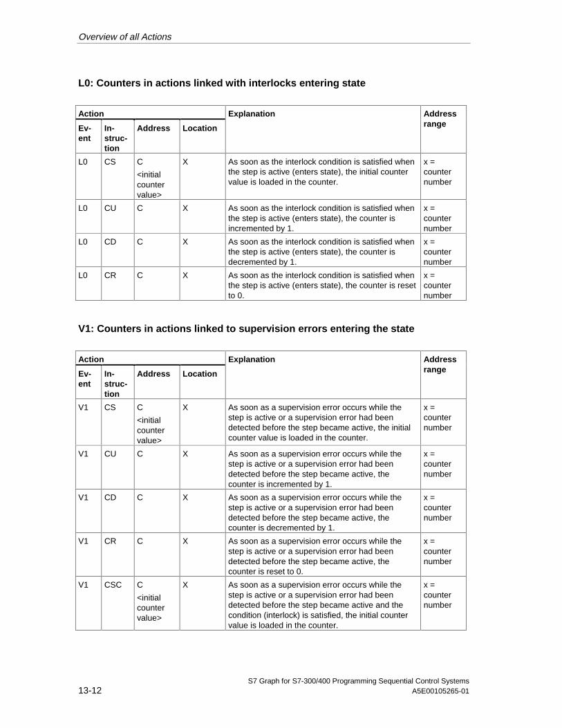
Overview of all Actions
S7 Graph for S7-300/400 Programming Sequential Control Systems13-12 A5E00105265-01
L0: Counters in actions linked with interlocks entering state
Action
Ev-ent
In-struc-tion
Address Location
Explanation Addressrange
L0 CS C
<initialcountervalue>
X As soon as the interlock condition is satisfied whenthe step is active (enters state), the initial countervalue is loaded in the counter.
x =counternumber
L0 CU C X As soon as the interlock condition is satisfied whenthe step is active (enters state), the counter isincremented by 1.
x =counternumber
L0 CD C X As soon as the interlock condition is satisfied whenthe step is active (enters state), the counter isdecremented by 1.
x =counternumber
L0 CR C X As soon as the interlock condition is satisfied whenthe step is active (enters state), the counter is resetto 0.
x =counternumber
V1: Counters in actions linked to supervision errors entering the state
Action
Ev-ent
In-struc-tion
Address Location
Explanation Addressrange
V1 CS C
<initialcountervalue>
X As soon as a supervision error occurs while thestep is active or a supervision error had beendetected before the step became active, the initialcounter value is loaded in the counter.
x =counternumber
V1 CU C X As soon as a supervision error occurs while thestep is active or a supervision error had beendetected before the step became active, thecounter is incremented by 1.
x =counternumber
V1 CD C X As soon as a supervision error occurs while thestep is active or a supervision error had beendetected before the step became active, thecounter is decremented by 1.
x =counternumber
V1 CR C X As soon as a supervision error occurs while thestep is active or a supervision error had beendetected before the step became active, thecounter is reset to 0.
x =counternumber
V1 CSC C
<initialcountervalue>
X As soon as a supervision error occurs while thestep is active or a supervision error had beendetected before the step became active and thecondition (interlock) is satisfied, the initial countervalue is loaded in the counter.
x =counternumber
05.04.0105.04.200105.04.2001

Overview of all Actions
S7 Graph for S7-300/400 Programming Sequential Control SystemsA5E00105265-01 13-13
Action
Ev-ent
In-struc-tion
Address Location
Explanation Addressrange
V1 CUC C X As soon as a supervision error occurs while thestep is active or a supervision error had beendetected before the step became active and thecondition (interlock) is satisfied, the counter isincremented by 1.
x =counternumber
V1 CDC C X As soon as a supervision error occurs while thestep is active or a supervision error had beendetected before the step became active and thecondition (interlock) is satisfied, the counter isdecremented by 1.
x =counternumber
V1 CRC C X As soon as a supervision error occurs while thestep is active or a supervision error had beendetected before the step became active and thecondition (interlock) is satisfied, the counter is resetto 0.
x =counternumber
V0: Counters in actions linked to supervision errors leaving the state
Action
Ev-ent
In-struc-tion
Address Location
Explanation Addressrange
V0 CS C
<initialcountervalue>
X As soon as a supervision error leaves the state (iseliminated or acknowledged), the initial countervalue is loaded in the counter.
x =counternumber
V0 CU C X As soon as a supervision error leaves the state (iseliminated or acknowledged), the counter isincremented by 1.
x =counternumber
V0 CD C X As soon as a supervision error leaves the state (iseliminated or acknowledged), the counter isdecremented by 1.
x =counternumber
V0 CR C X As soon as a supervision error leaves the state (iseliminated or acknowledged), the counter is reset to0.
x =counternumber
05.04.0105.04.200105.04.2001

Overview of all Actions
S7 Graph for S7-300/400 Programming Sequential Control Systems13-14 A5E00105265-01
A1: Counters in actions linked with a message acknowledgment
Action
Ev-ent
In-struc-tion
Address Location
Explanation Addressrange
A1 CS C
<initialcountervalue>
X As soon as a message is acknowledged), the initialcounter value is loaded in the counter.
x =counternumber
A1 CU C X As soon as a message is acknowledged, thecounter is incremented by 1.
x =counternumber
A1 CD C X As soon as a message is acknowledged, thecounter is decremented by 1.
x =counternumber
A1 CR C X As soon as a message is acknowledged, thecounter is reset to 0.
x =counternumber
A1 CSC C
<initialcountervalue>
X As soon as a message is acknowledged and thecondition (interlock) is satisfied, the initial countervalue is loaded in the counter.
x =counternumber
A1 CUC C X As soon a message is acknowledged and thecondition (interlock) is satisfied, the counter isincremented by 1.
x =counternumber
A1 CDC C X As soon a message is acknowledged and thecondition (interlock) is satisfied, the counter isdecremented by 1.
x =counternumber
A1 CRC C X As soon as a message is acknowledged and thecondition (interlock) is satisfied, the counter is resetto 0.
x =counternumber
R1: Counters in actions linked to setting a registration
Action
Ev-ent
In-struc-tion
Address Location
Explanation Addressrange
R1 CS C
<initialcountervalue>
X As soon as a registration is set, the initial countervalue is loaded in the counter.
x =counternumber
R1 CU C X As soon as a registration is set, the counter isincremented by 1.
x =counternumber
R1 CD C X As soon as a registration is set, the counter isdecremented by 1.
x =counternumber
05.04.0105.04.200105.04.2001

Overview of all Actions
S7 Graph for S7-300/400 Programming Sequential Control SystemsA5E00105265-01 13-15
Action
Ev-ent
In-struc-tion
Address Location
Explanation Addressrange
R1 CR C X As soon as a registration is set, the counter is resetto 0.
x =counternumber
R1 CSC C
<initialcountervalue>
X As soon as a registration is set and the condition(interlock) is satisfied, the initial counter value isloaded in the counter.
x =counternumber
R1 CUC C X As soon a registration is set and the condition(interlock) is satisfied, the counter is incrementedby 1.
x =counternumber
R1 CDC C X As soon a registration is set and the condition(interlock) is satisfied, the counter is decrementedby 1.
x =counternumber
R1 CRC C X As soon as a registration is set and the condition(interlock) is satisfied, the counter is reset to 0.
x =counternumber
05.04.0105.04.200105.04.2001
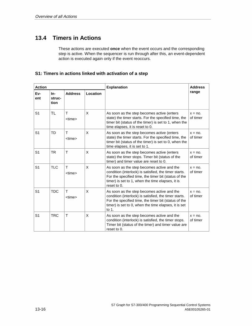
Overview of all Actions
S7 Graph for S7-300/400 Programming Sequential Control Systems13-16 A5E00105265-01
13.4 Timers in Actions
These actions are executed once when the event occurs and the correspondingstep is active. When the sequencer is run through after this, an event-dependentaction is executed again only if the event reoccurs.
S1: Timers in actions linked with activation of a step
Action
Ev-ent
In-struc-tion
Address Location
Explanation
Addressrange
S1 TL T
<time>
X As soon as the step becomes active (entersstate) the timer starts. For the specified time, thetimer bit (status of the timer) is set to 1, when thetime elapses, it is reset to 0.
x = no.of timer
S1 TD T
<time>
X As soon as the step becomes active (entersstate) the timer starts. For the specified time, thetimer bit (status of the timer) is set to 0, when thetime elapses, it is set to 1.
x = no.of timer
S1 TR T X As soon as the step becomes active (entersstate) the timer stops. Timer bit (status of thetimer) and timer value are reset to 0.
x = no.of timer
S1 TLC T
<time>
X As soon as the step becomes active and thecondition (interlock) is satisfied, the timer starts.For the specified time, the timer bit (status of thetimer) is set to 1, when the time elapses, it isreset to 0.
x = no.of timer
S1 TDC T
<time>
X As soon as the step becomes active and thecondition (interlock) is satisfied, the timer starts.For the specified time, the timer bit (status of thetimer) is set to 0, when the time elapses, it is setto 1.
x = no.of timer
S1 TRC T X As soon as the step becomes active and thecondition (interlock) is satisfied, the timer stops.Timer bit (status of the timer) and timer value arereset to 0.
x = no.of timer
05.04.0105.04.200105.04.2001
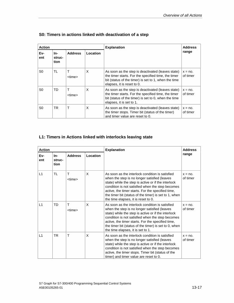
Overview of all Actions
S7 Graph for S7-300/400 Programming Sequential Control SystemsA5E00105265-01 13-17
S0: Timers in actions linked with deactivation of a step
Action
Ev-ent
In-struc-tion
Address Location
Explanation
Addressrange
S0 TL T
<time>
X As soon as the step is deactivated (leaves state)the timer starts. For the specified time, the timerbit (status of the timer) is set to 1, when the timeelapses, it is reset to 0.
x = no.of timer
S0 TD T
<time>
X As soon as the step is deactivated (leaves state)the timer starts. For the specified time, the timerbit (status of the timer) is set to 0, when the timeelapses, it is set to 1.
x = no.of timer
S0 TR T X As soon as the step is deactivated (leaves state)the timer stops. Timer bit (status of the timer)and timer value are reset to 0.
x = no.of timer
L1: Timers in Actions linked with interlocks leaving state
Action
Ev-ent
In-struc-tion
Address Location
Explanation
Addressrange
L1 TL T
<time>
X As soon as the interlock condition is satisfiedwhen the step is no longer satisfied (leavesstate) while the step is active or if the interlockcondition is not satisfied when the step becomesactive, the timer starts. For the specified time,the timer bit (status of the timer) is set to 1, whenthe time elapses, it is reset to 0.
x = no.of timer
L1 TD T
<time>
X As soon as the interlock condition is satisfiedwhen the step is no longer satisfied (leavesstate) while the step is active or if the interlockcondition is not satisfied when the step becomesactive, the timer starts. For the specified time,the timer bit (status of the timer) is set to 0, whenthe time elapses, it is set to 1.
x = no.of timer
L1 TR T X As soon as the interlock condition is satisfiedwhen the step is no longer satisfied (leavesstate) while the step is active or if the interlockcondition is not satisfied when the step becomesactive, the timer stops. Timer bit (status of thetimer) and timer value are reset to 0.
x = no.of timer
05.04.0105.04.200105.04.2001
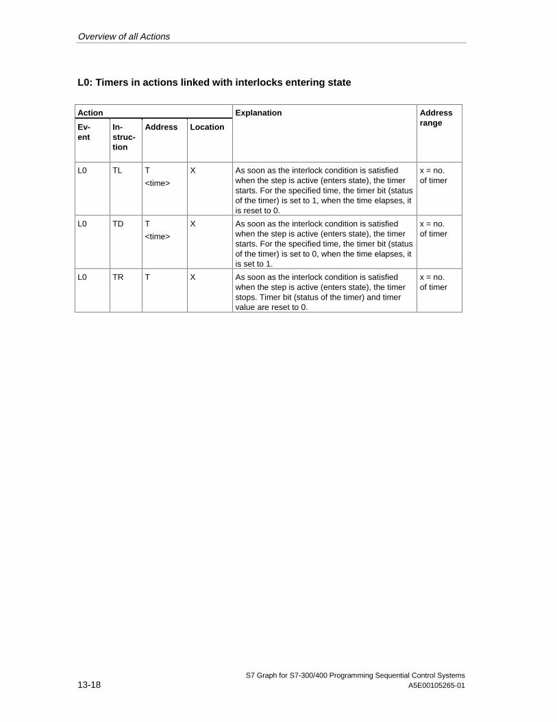
Overview of all Actions
S7 Graph for S7-300/400 Programming Sequential Control Systems13-18 A5E00105265-01
L0: Timers in actions linked with interlocks entering state
Action
Ev-ent
In-struc-tion
Address Location
Explanation
Addressrange
L0 TL T
<time>
X As soon as the interlock condition is satisfiedwhen the step is active (enters state), the timerstarts. For the specified time, the timer bit (statusof the timer) is set to 1, when the time elapses, itis reset to 0.
x = no.of timer
L0 TD T
<time>
X As soon as the interlock condition is satisfiedwhen the step is active (enters state), the timerstarts. For the specified time, the timer bit (statusof the timer) is set to 0, when the time elapses, itis set to 1.
x = no.of timer
L0 TR T X As soon as the interlock condition is satisfiedwhen the step is active (enters state), the timerstops. Timer bit (status of the timer) and timervalue are reset to 0.
x = no.of timer
05.04.0105.04.200105.04.2001
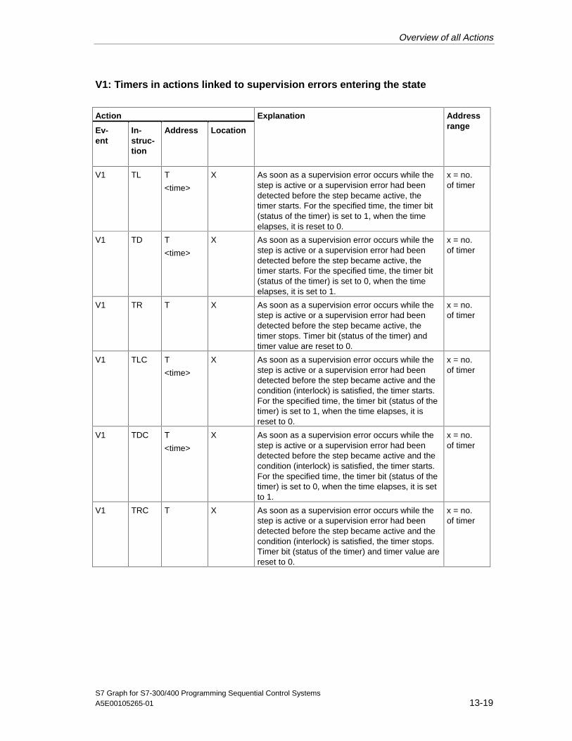
Overview of all Actions
S7 Graph for S7-300/400 Programming Sequential Control SystemsA5E00105265-01 13-19
V1: Timers in actions linked to supervision errors entering the state
Action
Ev-ent
In-struc-tion
Address Location
Explanation
Addressrange
V1 TL T
<time>
X As soon as a supervision error occurs while thestep is active or a supervision error had beendetected before the step became active, thetimer starts. For the specified time, the timer bit(status of the timer) is set to 1, when the timeelapses, it is reset to 0.
x = no.of timer
V1 TD T
<time>
X As soon as a supervision error occurs while thestep is active or a supervision error had beendetected before the step became active, thetimer starts. For the specified time, the timer bit(status of the timer) is set to 0, when the timeelapses, it is set to 1.
x = no.of timer
V1 TR T X As soon as a supervision error occurs while thestep is active or a supervision error had beendetected before the step became active, thetimer stops. Timer bit (status of the timer) andtimer value are reset to 0.
x = no.of timer
V1 TLC T
<time>
X As soon as a supervision error occurs while thestep is active or a supervision error had beendetected before the step became active and thecondition (interlock) is satisfied, the timer starts.For the specified time, the timer bit (status of thetimer) is set to 1, when the time elapses, it isreset to 0.
x = no.of timer
V1 TDC T
<time>
X As soon as a supervision error occurs while thestep is active or a supervision error had beendetected before the step became active and thecondition (interlock) is satisfied, the timer starts.For the specified time, the timer bit (status of thetimer) is set to 0, when the time elapses, it is setto 1.
x = no.of timer
V1 TRC T X As soon as a supervision error occurs while thestep is active or a supervision error had beendetected before the step became active and thecondition (interlock) is satisfied, the timer stops.Timer bit (status of the timer) and timer value arereset to 0.
x = no.of timer
05.04.0105.04.200105.04.2001

Overview of all Actions
S7 Graph for S7-300/400 Programming Sequential Control Systems13-20 A5E00105265-01
V0: Timers in Actions linked to supervision errors leaving the state
Action
Ev-ent
In-struc-tion
Address Location
Explanation
Addressrange
V0 TL T
<time>
X As soon as a supervision error leaves the state(is eliminated or acknowledged), the timer starts.For the specified time, the timer bit (status of thetimer) is set to 1, when the time elapses, it isreset to 0.
x = no.of timer
V0 TD T
<time>
X As soon as a supervision error leaves the state(is eliminated or acknowledged), the timer starts.For the specified time, the timer bit (status of thetimer) is set to 0, when the time elapses, it is setto 1.
x = no.of timer
V0 TR T X As soon as a supervision error leaves the state(is eliminated or acknowledged), the timer stops.Timer bit (status of the timer) and timer value arereset to 0.
x = no.of timer
A1: Timers in actions linked with a message acknowledgment
Action
Ev-ent
In-struc-tion
Address Location
Explanation
Addressrange
A1 TL T
<time>
X As soon as a message is acknowledged, thetimer starts. For the specified time, the timer bit(status of the timer) is set to 1, when the timeelapses, it is reset to 0.
x = no.of timer
A1 TD T
<time>
X As soon as a message is acknowledged, thetimer starts. For the specified time, the timer bit(status of the timer) is set to 0, when the timeelapses, it is set to 1.
x = no.of timer
A1 TR T X As soon as a message is acknowledged, thetimer stops. Timer bit (status of the timer) andtimer value are reset to 0.
x = no.of timer
A1 TLC T
<time>
X As soon as a message is acknowledged and thecondition (interlock) is satisfied, the timer starts.For the specified time, the timer bit (status of thetimer) is set to 1, when the time elapses, it isreset to 0.
x = no.of timer
05.04.0105.04.200105.04.2001

Overview of all Actions
S7 Graph for S7-300/400 Programming Sequential Control SystemsA5E00105265-01 13-21
Action
Ev-ent
In-struc-tion
Address Location
Explanation
Addressrange
A1 TDC T
<time>
X As soon as a message is acknowledged and thecondition (interlock) is satisfied, the timer starts.For the specified time, the timer bit (status of thetimer) is set to 0, when the time elapses, it is setto 1.
x = no.of timer
A1 TRC T X As soon as a message is acknowledged and thecondition (interlock) is satisfied, the timer stops.Timer bit (status of the timer) and timer value arereset to 0.
x = no.of timer
R1: Timers in actions linked to setting a registration
Action
Ev-ent
In-struc-tion
Address Location
Explanation
Addressrange
R1 TL T
<time>
X As soon as a registration is set, the timer starts.For the specified time, the timer bit (status of thetimer) is set to 1, when the time elapses, it isreset to 0.
x = no.of timer
R1 TD T
<time>
X As soon as a registration is set, the timer starts.For the specified time, the timer bit (status of thetimer) is set to 0, when the time elapses, it is setto 1.
x = no.of timer
R1 TR T X As soon as a registration is set, the timer stops.Timer bit (status of the timer) and timer value arereset to 0.
x = no.of timer
R1 TLC T
<time>
X As soon as a registration is set and the condition(interlock) is satisfied, the timer starts. For thespecified time, the timer bit (status of the timer) isset to 1, when the time elapses, it is reset to 0.
x = no.of timer
R1 TDC T
<time>
X As soon as a registration is set and the condition(interlock) is satisfied, the timer starts. For thespecified time, the timer bit (status of the timer) isset to 0, when the time elapses, it is set to 1.
x = no.of timer
R1 TRC T X As soon as a registration is set and the condition(interlock) is satisfied, the timer stops. Timer bit(status of the timer) and timer value are reset to0.
x = no.of timer
05.04.0105.04.200105.04.2001

Overview of all Actions
S7 Graph for S7-300/400 Programming Sequential Control Systems13-22 A5E00105265-01
13.5 Arithmetic in Actions
These actions are either executed in every cycle in which the relevant step is activeor once when the relevant event occurs.
Action Explanation
Ev-ent
In-struc-tion
Assignment
-- N A:=B
A:=func(B)
A:=B<operator>C
As long as the step is active, the arithmetic is executed.
-- NC A:=B
A:=func(B)
A:=B<operator>C
As long as the step is active and the condition (interlock) issatisfied, the arithmetic is executed.
S1: Arithmetic in actions linked with activation of a step
Action Explanation
Ev-ent
In-struc-tion
Assignment
S1 N A:=B
A:=func(B)
A:=B<operator>C
As soon as the step becomes active (enters state), the arithmetic isexecuted.
S1 NC A:=B
A:=func(B)
A:=B<operator>C
As soon as the step becomes active (enters state) and thecondition (interlock) is satisfied, the arithmetic is executed.
05.04.0105.04.200105.04.2001
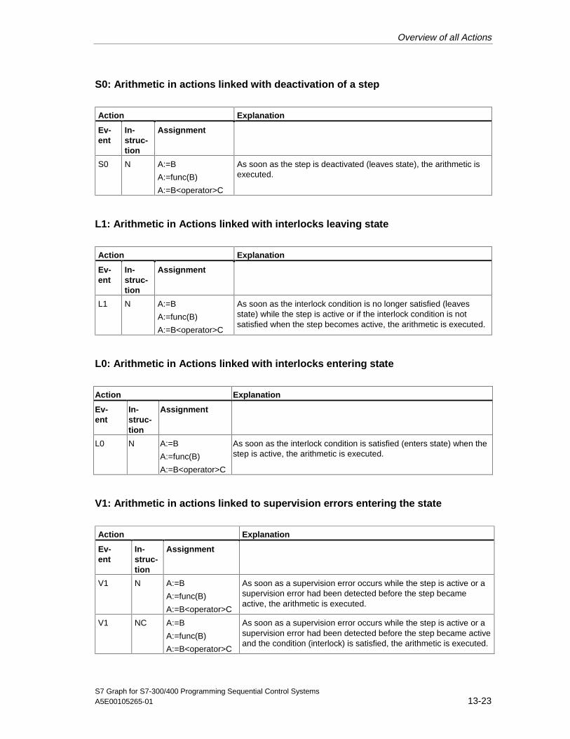
Overview of all Actions
S7 Graph for S7-300/400 Programming Sequential Control SystemsA5E00105265-01 13-23
S0: Arithmetic in actions linked with deactivation of a step
Action Explanation
Ev-ent
In-struc-tion
Assignment
S0 N A:=B
A:=func(B)
A:=B<operator>C
As soon as the step is deactivated (leaves state), the arithmetic isexecuted.
L1: Arithmetic in Actions linked with interlocks leaving state
Action Explanation
Ev-ent
In-struc-tion
Assignment
L1 N A:=B
A:=func(B)
A:=B<operator>C
As soon as the interlock condition is no longer satisfied (leavesstate) while the step is active or if the interlock condition is notsatisfied when the step becomes active, the arithmetic is executed.
L0: Arithmetic in Actions linked with interlocks entering state
Action Explanation
Ev-ent
In-struc-tion
Assignment
L0 N A:=B
A:=func(B)
A:=B<operator>C
As soon as the interlock condition is satisfied (enters state) when thestep is active, the arithmetic is executed.
V1: Arithmetic in actions linked to supervision errors entering the state
Action Explanation
Ev-ent
In-struc-tion
Assignment
V1 N A:=B
A:=func(B)
A:=B<operator>C
As soon as a supervision error occurs while the step is active or asupervision error had been detected before the step becameactive, the arithmetic is executed.
V1 NC A:=B
A:=func(B)
A:=B<operator>C
As soon as a supervision error occurs while the step is active or asupervision error had been detected before the step became activeand the condition (interlock) is satisfied, the arithmetic is executed.
05.04.0105.04.200105.04.2001
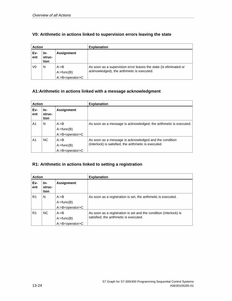
Overview of all Actions
S7 Graph for S7-300/400 Programming Sequential Control Systems13-24 A5E00105265-01
V0: Arithmetic in actions linked to supervision errors leaving the state
Action Explanation
Ev-ent
In-struc-tion
Assignment
V0 N A:=B
A:=func(B)
A:=B<operator>C
As soon as a supervision error leaves the state (is eliminated oracknowledged), the arithmetic is executed.
A1:Arithmetic in actions linked with a message acknowledgment
Action Explanation
Ev-ent
In-struc-tion
Assignment
A1 N A:=B
A:=func(B)
A:=B<operator>C
As soon as a message is acknowledged, the arithmetic is executed.
A1 NC A:=B
A:=func(B)
A:=B<operator>C
As soon as a message is acknowledged and the condition(interlock) is satisfied, the arithmetic is executed.
R1: Arithmetic in actions linked to setting a registration
Action Explanation
Ev-ent
In-struc-tion
Assignment
R1 N A:=B
A:=func(B)
A:=B<operator>C
As soon as a registration is set, the arithmetic is executed.
R1 NC A:=B
A:=func(B)
A:=B<operator>C
As soon as a registration is set and the condition (interlock) issatisfied, the arithmetic is executed.
05.04.0105.04.200105.04.2001

S7 Graph for S7-300/400 Programming Sequential Control SystemsA5E00105265-01 14-1
14 Configuration Instructions
Introduction
To automate your sequential control system with S7 Graph, in addition to thefunctions for the automatic mode, a range of further functions is also available.Before you can use the S7 Graph functions, you must make sure that certainconditions are met. To make it easier for you to get used to S7 Graph, the mostimportant points are summarized in this chapter in the form of brief configurationinstructions.
The following aspects are dealt with:
• Which general structures exist and how do these affect the program structureof the sequencer?
• What is important when programming and using sequencers?
• How are operator interface systems connected?
05.04.0105.04.200105.04.2001

Configuration Instructions
S7 Graph for S7-300/400 Programming Sequential Control Systems14-2 A5E00105265-01
14.1 General Level and Program Structure
Level Structure Based on the Example of a Manufacturing Cell
When using S7 Graph, remember that the sequencer is designed primarily toconfigure sequential processes clearly and simply. Apart from these sequenceswith which, for example, the parts of a manufacturing unit can be coordinated,additional higher-level functions (cell level) and lower-level functions (function orunit level) are also required.
The sequencer programmed with S7 Graph belongs to the coordination level, butmust take into account the interdependencies from the cell level and the unit level.
Enableoperation
Modes
Hydraulics
Pneumatics
Save,remove
Conveyor belt
Motor memory
Coolant
Cell level
Coordinationlevel
Function orunit level
General
Utilities
Station n: Save
Turn
Insert,weld
Clamp
Centerer
Station 1: Insert
Turntable
The individual levels have the following significance:
• Cell levelThe cell level encompasses functions with a central or wider reachingsignificance, for example preparations for enabling operation and modes.The blocks at the cell level provide signals that are relevant for all blocks of thecoordination and unit level in this cell.
• Coordination levelThe coordination level includes various coordination functions, for example forthe automatic mode and retraction following a break in operation. For eachstation, at least one sequencer is required for coordination at this level.
• Unit levelThe unit level includes functions for activating individual units of equipment, forexample motors and valves. This includes all the lower-level functions, forexample interlocks and supervision conditions independent of the sequencerand direct manual intervention in the operation of the units.
05.04.0105.04.200105.04.2001
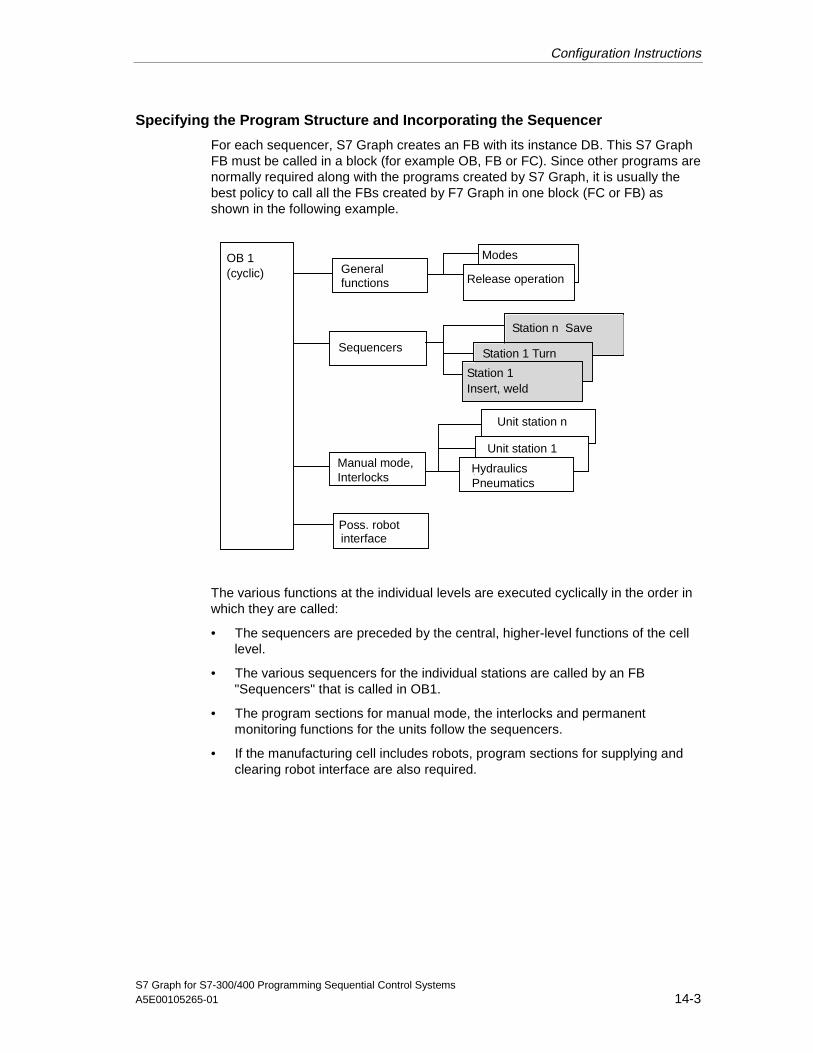
Configuration Instructions
S7 Graph for S7-300/400 Programming Sequential Control SystemsA5E00105265-01 14-3
Specifying the Program Structure and Incorporating the Sequencer
For each sequencer, S7 Graph creates an FB with its instance DB. This S7 GraphFB must be called in a block (for example OB, FB or FC). Since other programs arenormally required along with the programs created by S7 Graph, it is usually thebest policy to call all the FBs created by F7 Graph in one block (FC or FB) asshown in the following example.
Station n Save
Manual mode,Interlocks
OB 1(cyclic)
Sequencers
Modes
Release operation
Poss. robotinterface
HydraulicsPneumatics
Unit station 1
Station 1 Turn
Station 1Insert, weld
Unit station n
Generalfunctions
The various functions at the individual levels are executed cyclically in the order inwhich they are called:
• The sequencers are preceded by the central, higher-level functions of the celllevel.
• The various sequencers for the individual stations are called by an FB"Sequencers" that is called in OB1.
• The program sections for manual mode, the interlocks and permanentmonitoring functions for the units follow the sequencers.
• If the manufacturing cell includes robots, program sections for supplying andclearing robot interface are also required.
05.04.0105.04.200105.04.2001

Configuration Instructions
S7 Graph for S7-300/400 Programming Sequential Control Systems14-4 A5E00105265-01
Enabling Operation
In production facilities, utilities such as hydraulic and pneumatic systems are oftenrequired and the functions of all other units depend on them being available. Ittherefore makes sense to turn on the hydraulic and pneumatic systems centrallyafter turning on the machinery and to generate ready signals for the other blocks.
The following diagram is an example of how general operation of the system canbe enabled in S7 Graph.
T1Trans1
S2Con...
T2
Trans2
S3Uni...
T3
Trans3
T4
Trans4
"Controlpow_ok"
"Hydraulic_ok"
"Central_start"
S1Init
"Emer_off"
S5Pro...
T5
Trans5
"Acknowledge"
S2
InitR "Unit_ready"R "Process_enabled"
Controller_on
N "Controller_on"
CMP
MD6
Init.U >=D
"Pneumatic_ok"
Unit_readyN "Unit_ready"
S4Pro...
Process_enabled
N "Unit_ready"
N "Process_enabled"
"Door_closed"
No_Process_enabled
T6
Trans6
"Hydraulic_ok"
"Pneuma-tic_ok"
S2
T5T6
• After turning on the controller, step 1 (initial step) is activated using theINIT_SQ parameter and the signals Unit_ready and Process_enabled arereset.
• After a specified minimum waiting time, step 2 turns on the hydraulic andpneumatic units dependent on the signal Controlpow_ok (control voltage OK)using the Controller_on action.
05.04.0105.04.200105.04.2001

Configuration Instructions
S7 Graph for S7-300/400 Programming Sequential Control SystemsA5E00105265-01 14-5
• After the feedback indicating that the hydraulic and pneumatic systems are OK,step 3 outputs the message Unit_ready (to various recipients including thecentral controller).
• Triggered by the signal "Central_start" (start main console of the productionequipment), step 4 sets the unit to the ready state and enables automaticexecution.
• With "Emer_off" or loss of the signal "Door_closed", the change to step 5cancels the Process_enabled. If this is acknowledged, there is a jump tostep 2.
• If a step enabling condition from one of the power systems is canceled whilethe Process_enabled (step 4) is active, the enable signals are also canceledwith the change to step 2. Once the step enabling conditions ("OK_Signal") ofthe power systems are present again, Central_start can return the unit to theenabled state again.
• The signals "Controller_on", "Unit_ready" and "Process_enabled" are sent tothe other blocks and the central controller.
• The "Unit_ready" signal also enables the mode selection in the mode block.
• The "Process_enabled" signal enables the automatic mode.
Handling Modes
Depending on the situation, the user requires different modes for the system andmachinery. In unlinked manufacturing cells, for example in body work assembly,these are the modes:
• Automatic
• Inching, in other words a variant of the automatic mode with a stop after eachprocess step
• Automatic or switch to next; in other words the automatic mode with anadditional step enabling condition
• Manual/setup, in other words direct influence on the units or functions
05.04.0105.04.200105.04.2001

Configuration Instructions
S7 Graph for S7-300/400 Programming Sequential Control Systems14-6 A5E00105265-01
The modes, however, do not have the same effects at all levels. The followingoverview lists the modes and their effects at the coordination level and unit level(motors, valves etc.).
Mode Effect at the coordination level Effect at the unit level
Automatic Sequencer passes control to next step whenthe transition is satisfied.
Enabling of the drive by the sequencer
Inching The sequencer passes control to the next stepwhen the transition is satisfied and the "Inching"button signal enables the next step.
Enabling of the drive by the sequencer
Automatic orstepby step mode
The sequencer progresses when the transitionis satisfied or the "Inching" button signalenables the next step.
Enabling of the drive by the sequencer
Manual orsetup
Enabling of next step suppressed, the status ofthe sequencer has no effect at the unit level.
Drive enabled by direction buttons
Representing the Mode in the Sequencer
If, for example, a selector switch on the control panel supplies the signalsautomatic, inching, and manual as individual single signals, only relatively simplelogic is required to derive the mode signals for the sequencers and for theunderlying drives of the units as shown in principle in the following diagram.
FB unit group n
AutomaticManual
SW_MAN
SW_AUTOSW_TAPSeq_Auto
Seq_Inch
Seq_Man
Autom.
Inching
Manual
Unit_Auto
Unit_Hand
Processenable
Modeselector
FB unit group 1
Automaticmanual
SW_MAN
SW_AUTOSW_TAP
FB sequencer n
Mode setting
FB sequencer 1&
&
&
&>1_
>1_
The modes selected at the console are passed on to the sequencers whenProcess_enabled is active. If Process_enabled is not set, the modes of thesequencers are switched to SW_MAN and step enabling is suppressed.
05.04.0105.04.200105.04.2001

Configuration Instructions
S7 Graph for S7-300/400 Programming Sequential Control SystemsA5E00105265-01 14-7
In the automatic or inching modes, the automatic mode is set for the unit functions.The manual mode is passed on directly. If there is no process_enabled, bothmodes are reset and the process is stopped. The functions of the unit groups arerepresented in an FB created with LAD/FBD or STL.
Handling the Interlocks and Manual Control in the Manual Mode
In S7 Graph, the sequencer controls the functions for the automatic mode. Thefunctions for the manual mode required over and above those of the automaticmode are included in a separate FB. Using action bits (for example Carr_fwd) thesequencer is connected to the interlock and manual control.
S 4
S 5
&
&
&
Carr_fwdAutom.
Man
Btn_fwd
KM_on
Carr_fwd
Spind_on
Execute
Mot_onS
S
N
FB interlock/manual control
FB sequencer
&
Cnd1Cnd2Cnd3Cnd4
( )
( )
_>1
Enable_fwd
Valve1_fwd
Enable_fwd
The permanent monitoring functions required for the units can be programmed withS7 PDIAG. Depending on the requirements, the supervision conditions can beformulated so that they are effective both in the automatic and manual modes orspecific supervision conditions are programmed for the automatic mode and for themanual mode.
05.04.0105.04.200105.04.2001
Configuration Instructions
S7 Graph for S7-300/400 Programming Sequential Control Systems14-8 A5E00105265-01
14.2 Points to Note about Programming Sequencers
Initialization
The sequencer is initialized using the INIT_SQ parameter. If this changes to "1", allsteps marked as initial steps are activated. All other steps are deactivated.
After turning on the controller, the sequencer is in the same mode as it was whenthe controller was turned off, in other words if the controller was in the SW_AUTOmode before it was turned off, it will be in this mode when it is turned on again. Ifyou want to avoid this, the sequencer must be set to the required mode (forexample SW_MAN) explicitly when it is turned on, for example using theinitialization signal.
If the status of the process (system or machine) does not correspond to the initialstate of the sequencer, you can deal with this in two ways:
• The process is, for example, changed to the initial state by a command.If you want to change the process to the initial state, it is usually advisable tocreate a separate sequencer for this purpose.
• The sequencer must be synchronized with the process state using thesynchronize function, in other words, the sequencer must be set to the currentpart of the process.
Which method you use depends on the type of process.
Interlocks
In S7 Graph, interlocks can be defined for each step. All actions that are executeddepending on a condition are only activated when the interlock conditions aresatisfied.
If the interlock conditions are not satisfied when the step is active, an errormessage is sent to the console (for example operator panel). The error is clearedwhen the interlock conditions are satisfied.
Supervisions
In S7 Graph, monitoring conditions can be defined in the form of supervisions foreach step. The most common supervision condition is the execution time of theactions. If the supervision condition is satisfied, in other words an error hasoccurred, an error message is sent to the console (for example operator panel).Such errors are acknowledged via the ACK_EF parameter.
The compilation settings (menu command Options > Block Settings) decidewhether an acknowledgment is be required when an S7 Graph FB is created.
• Compilation options "Acknowledge Errors" checked:The error is cleared only when an acknowledgment signal is sent and thesupervision is no longer satisfied or when an acknowledgment signal is sentand the successor transition is satisfied.
05.04.0105.04.200105.04.2001
Configuration Instructions
S7 Graph for S7-300/400 Programming Sequential Control SystemsA5E00105265-01 14-9
If time monitoring was programmed with Si.U, the acknowledgment signalresets the monitoring time so that the supervision condition is no longersatisfied.
• Compilation options "Acknowledge Errors" not checked:The error is cleared when the supervision conditions are no longer satisfied.
Caution
If the step enabling condition is satisfied during the acknowledgment cycle, thenext step is enabled.
Please remember that the supervisions defined in the sequencer are specific to aparticular step and only monitor the execute time of the relevant actions. If, forexample, a motor is turned on in step 1, the run-up time can be monitored in step1. Once this step is deactivated, the motor is no longer monitored in thesequencer. If you want the motor to be monitored permanently and independent ofthe sequencer, this must implemented at the underlying unit level.
Abort Situations
Abort situations occur when an "immediate stop" or "emergency off" is set due to acritical situation or when a fault occurs in units. In these situations, the followingoperations are carried out:
• The sequencers are stopped by switching to SW_MAN.
• At the unit level, the output signals are deactivated by resetting the automaticenable.
Synchronization
Synchronization of the sequencer with the state of the process or machine isrequired at least in the following situations:
• Case 1: A program change in the installation and startup phase meant that theinstance DB had to be regenerated.
• Case 2: In the manual mode, units were controlled manually so that the stateof the sequencer no longer corresponds to the state of the process or machine.Following a manual intervention, and depending on the process, the automaticmode must be resumed starting at the current state of the system or machine;in other words, the current position of the sequencer must be adapted to theprocess (synchronized).
In Case 1, the menu command Debug > Control Sequencer can be used in themanual mode to set and reset steps directly when working on the programmingdevice so that the state that existed before the program change can be set.
05.04.0105.04.200105.04.2001
Configuration Instructions
S7 Graph for S7-300/400 Programming Sequential Control Systems14-10 A5E00105265-01
In Case 2, synchronization can be achieved directly working on the programmingdevice. Synchronization then involves the following steps:
1. Select the menu command Options > Block Settings and make sure that the"Synchronization" option is selected in the "Compile/Save" tab.
2. Select the menu command Debug > Synchronization.
Result: All transition and interlock conditions are detected. The subsequentevaluation shows which steps are located between a satisfied and non-satisfiedtransition. All steps found are displayed yellow.
3. Click all the steps you want to select with the mouse pointer that changes to across-hair.
4. Select the steps with the "Activate" button.
In principle, you can also synchronize using a console (for example operatorpanel). This is possible when permanent execution of transitions and interlockconditions is triggered at the console and the results are displayed and requiredsteps can be activated on the console.
Program-controlled synchronization is also possible, when, for example a buttonsignal brings about a change from the initial step to synchronization in a"Synchronization" step in which process state transitions leaving the state areevaluated. Using jump commands, the sequencer can then jump to the suitablestep.
Modifications during Installation and Commissioning
If changes are made to the sequencer structure during installation andcommissioning, for example a step is added, deleted, or renumbered or a transitionis deleted or added, a new instance DB is created when you compile thesequencer. Downloading the instance DB to the PLC has the same effect asinitialization with the INIT_SQ input, in other words all initial steps are active and allother steps are inactive. The actions are, however, not automatically invalidated.Download the instance DB only in the manual mode to avoid errors that can occurwhen the data are overwritten.
Using the menu command Debug > Control Sequencer, you can reset thesequencer to the process state that applied before the modification was made.
Caution
With the menu command Debug > Control Sequencer, you can change themode of the sequencer directly in S7 Graph. If the sequencer and underlyingmonitoring/manual functions are supplied with parameters as described inHandling Modes, this means that the mode of the sequencer no longer matchesthe underlying function. If you want to prevent this, the mode change triggered onthe programming device can be disabled. The following diagram illustrates theprinciple.
05.04.0105.04.200105.04.2001
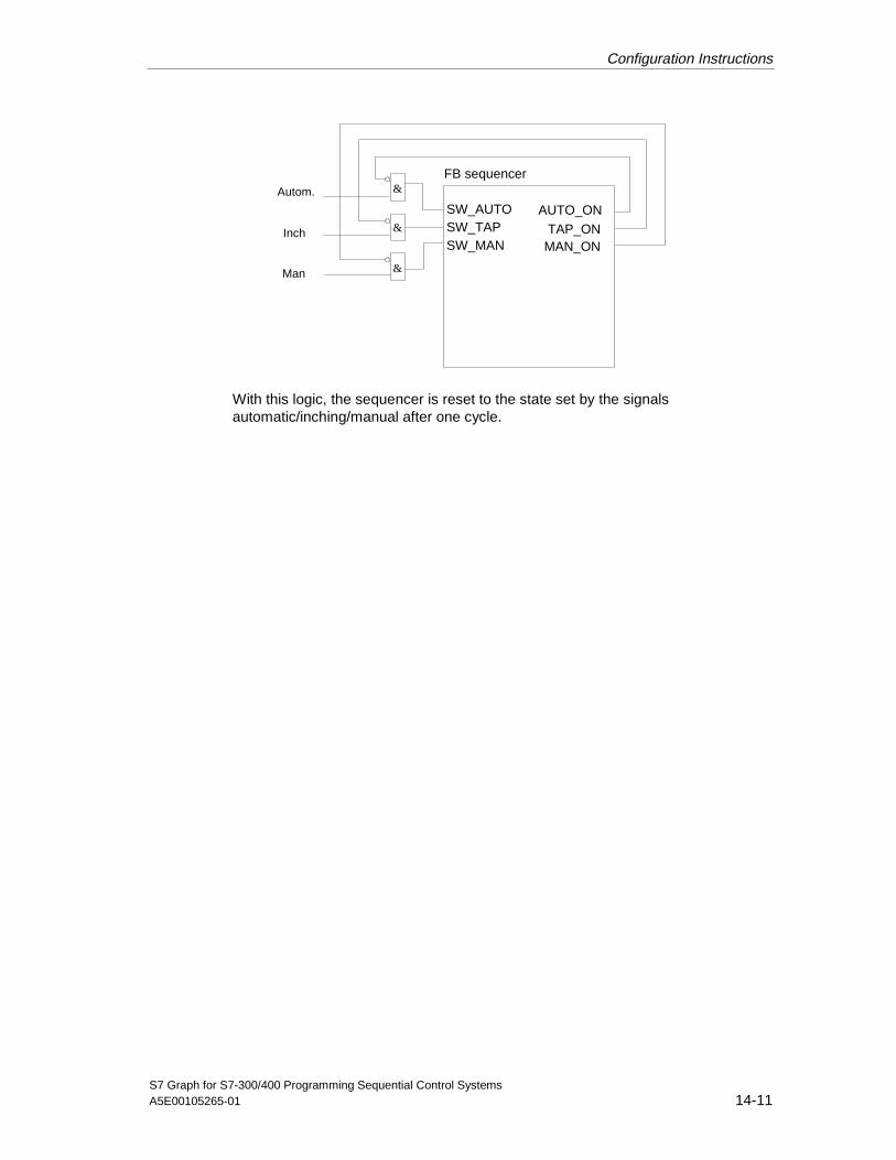
Configuration Instructions
S7 Graph for S7-300/400 Programming Sequential Control SystemsA5E00105265-01 14-11
SW_MAN
SW_AUTOSW_TAP
Autom.
Inch
Man
&
&
&
FB sequencer
AUTO_ONTAP_ON
MAN_ON
With this logic, the sequencer is reset to the state set by the signalsautomatic/inching/manual after one cycle.
05.04.0105.04.200105.04.2001
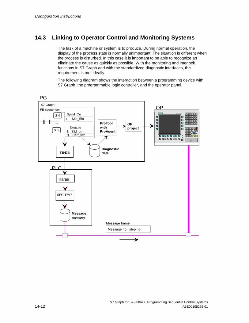
Configuration Instructions
S7 Graph for S7-300/400 Programming Sequential Control Systems14-12 A5E00105265-01
14.3 Linking to Operator Control and Monitoring Systems
The task of a machine or system is to produce. During normal operation, thedisplay of the process state is normally unimportant. The situation is different whenthe process is disturbed. In this case it is important to be able to recognize aneliminate the cause as quickly as possible. With the monitoring and interlockfunctions in S7 Graph and with the standardized diagnostic interfaces, thisrequirement is met ideally.
The following diagram shows the interaction between a programming device withS7 Graph, the programmable logic controller, and the operator panel.
FB/DB
FB/DB
Message no., step no.
Message frame
OP
Message memory
PG
PLC
ProToolwithProAgent
OP project
Diagnostic data
SFC 17/18
Mot_EinSS 4
S 5
FB sequencer
S7 Graph
Spind_On
ExecuteKM_onCarr_fwd
SN
05.04.0105.04.200105.04.2001

Configuration Instructions
S7 Graph for S7-300/400 Programming Sequential Control SystemsA5E00105265-01 14-13
Creating Diagnostic Data
When you compile a sequencer, you can decide whether diagnostic data shouldalso be created in addition to the FB/DB providing the "message withALARM_SQ/ALARM_S" option is selected. The diagnostic data contains thestructure data of a sequencer and can be linked into a corresponding OP projectusing ProAgent.
This makes the following functions possible on the operator panel:
• Display of the current state of the sequencer with current sequencer namesand step names
• Display of a disturbed step (step number and name)
• Display of the cause of a disturbance, in other words:
- If a supervision error occurs: Display of the missing step enabling condition
- If an interlock error occurs: Display of the missing interlock condition.
If you have modified addresses in the SIMATIC manager using the Rewire menucommand, and the addresses are also used by the sequencer, the correspondingdiagnostic data are only updated when you open the corresponding S7 Graph FBagain and save it.
Creating Messages
To display disturbances on, for example, an operator panel, you must click theoption "Message with ALARM_SQ/ALARM_S (SFC17/SFC18) in the "Messages"tab that you can display with the menu command Options > Block Settings. If thisoption is selected, a message is entered in the message memory of the CPU bythe selected SFC and automatically transferred to the operator panels. Themessage frame contains not only the automatically assigned message number butalso the current step number so that the operator panel can display thecorresponding texts and depending on the display, the corresponding conditions.
Apart from the message, a group error bit is also set that is displayed on theoperator panel depending on the display.
The following displays are available on the operator panel for the sequencer:
• Overview levelAll units are displayed with their current step. Each sequencer block representssuch a unit. If a sequencer has a disturbance, this line is marked by . I f thisline is selected, you can change directly to the detailed display level with afunction key.
• Message display levelThe current message with the date and time is displayed. You can changedirectly to the detailed display from this level.
05.04.2001

Configuration Instructions
S7 Graph for S7-300/400 Programming Sequential Control Systems14-14 A5E00105265-01
• Detailed displayThe network affected is displayed in Ladder Logic or statement listrepresentation and the missing conditions are marked. In the display, you alsohave the option of displaying the entire network or the reduced networkcontaining only the conditions affected. This is particularly useful with moreextensive logic operations.
Note
• If you use the standard FC71, you do not require the SFC17/SFC18 blocks.Messages are, however, processed using SFC52 ("WR_USMSG").
• If you use the standard FC73, no messages are generated due to theminimized memory configuration.
05.04.0105.04.200105.04.2001

S7 Graph for S7-300/400 Programming Sequential Control SystemsA5E00105265-01 15-1
15 Instance DB
Each S7 Graph FB is assigned an instance data block that can be understood asrepresenting the memory of the FB. It contains the data belonging to thesequencer, in other words all the data and parameters required to execute the FB:
• All the FB parameters of the selected FB parameter set
step-transition description (for example current or last activation time of a step withand without disturbance times; indicator whether or not a step is active).
The data are entered automatically.
15.1 Settings for the Instance DB
Include Instance DB
To create the instance DB automatically after compiling an error-free FB, click theoption "Include Instance DB" in the "General" tab (menu command Options >Application Settings). If you select this option, whenever you compile ordownload the block, S7 Graph checks whether it is necessary to create or updatethe instance DB and takes whatever action is necessary.
Interface Description
In the "Save/Compile" tab, there are three possible settings for the interfacedescription of the instance DB:
• Memory minimized (as of V5.1)The interface descriptions are stored in the instance DB as structures. Aseparate structure with the essential information is created for each step andeach transition of the sequencer. This option reduces the memoryrequirements of your S7 Graph FB considerably. The blocks created do not,however, have diagnostic capability. When you monitor the sequential controlsystem, you see the status display for conditions for the active step only.If you use this option, you must use the supplied FC75 standard block.
• Structure ArraysThe interface descriptions are stored in the instance DB as fields (ARRAYs).This option optimizes the memory requirements of your S7 Graph functionblock. The step names are, however, not stored. Symbolic addressing of otherblocks is not possible in this case.
05.04.0105.04.200105.04.2001
Instance DB
S7 Graph for S7-300/400 Programming Sequential Control Systems15-2 A5E00105265-01
• Individual StructuresThe interface descriptions are stored in the instance DB as structures(STRUCT). A separate structure with detailed information is created for eachstep and each transition of the sequencer. This is a convenient methodallowing internal and external access using symbolic names. The instance DBcan be evaluated both using direct access to the data or using the step andtransition names. The structures increase the size of the instance DB but donot affect the performance when executing the sequencer.
15.2 Assignment of Instance DB and S7 Graph FB
In general, S7 Graph makes an automatic DB assignment for blocks. If the DB withthe same number as the FB does not yet exist or the DB and FB match, the DB isautomatically assigned. In all other cases (even when compiling source files), youmust enter the number of the DB. Follow the steps outlined below:
• Select the menu command File > Modify/Adapt Instance DB Number andenter a new DB name in the dialog box that is opened. An instance DBmatching the FB is created.
Proposed DB Number when First Compiling a Source File
When an instance DB is created the first time (either automatically or manually),S7 Graph proposes a DB number in a dialog box that is the same as the number ofthe current FB. If your function block, for example, is called "FB6", S7 Graphproposes "DB6". You can either accept the proposed DB name or click the "Select"button and specify a different DB name or a different path.
05.04.0105.04.200105.04.2001
Instance DB
S7 Graph for S7-300/400 Programming Sequential Control SystemsA5E00105265-01 15-3
15.3 Automatic Creation of the Instance DB on Saving
If you have set the option "Include Instance DB" in the "General" tab that youdisplay with the menu command Options > Block Settings , follow the stepsbelow:
• Program the S7 Graph FB and select the menu command File > Save.
Result: The S7 Graph FB is saved and the instance DB is created.
Caution
The data block must not be created manually or deleted if you have set the option"message with ALARM_SQ / ALARM_S (SFC17 / SFC18)" in the "Messages" tab(menu command Options > Block Settings) otherwise messages can be lost.The instance data block is then included automatically.
15.4 Creating the Instance DB Later
If you have not selected the option "Include Instance DB" in the "General" tab,follow the steps below:
1. Program the S7 Graph FB and select the menu command File > Save.
2. If the S7 Graph FB was compiled free of errors, select the menu command File> Create Instance DB.
Result: A new instance DB is created or the selected instance DB isoverwritten.
15.5 Displaying and Printing the Content of the Instance DB
To display and print the content of the instance DB, follow the steps outlined below:
1. While in the SIMATIC Manager, open the DB in the relevant user program bydouble-clicking it.
2. Select the menu command View > Data View in the LAD/STL/FBD editor.
3. To print the content of the instance DB, select the menu command File > Print.
05.04.0105.04.200105.04.2001

Instance DB
S7 Graph for S7-300/400 Programming Sequential Control Systems15-4 A5E00105265-01
15.6 Accessing the Instance DB
You can access the instance DB internally, in other words within the S7 Graph FB(for example as an action linked to an event) or externally, in other words outsidethe S7 Graph FB (for example linked to a different block).
Access to the Data of the Instance DB
You can access the instance DB with STEP 7 tools. We strongly advise, however,that you do not edit the DB.
15.7 Structure of an Instance DB
The structure of the instance DB depends on the settings you make in the"Compile / Save" tab (menu command Options > Block Settings ). The followingfactors affect the content and the size.
1. The parameter set selected for the FB
2. The interface description for the data belonging to steps and transitions(memory minimized/structure arrays/individual structures). The data areentered automatically.
3. The option of entering criteria analysis data.
4. Number and size of user-defined variables
15.8 Outline of the Structure of the Instance DB
The following table illustrates the divisions within the instance DB.
Area Identifier Length
FB parameters Names of the input and outputparameters of the S7 Graph FB
Depends on the selected parameter set:
2 bytes: minimum10 bytes: Standard/MaximumIndividual: Maximum V5/User-def.
Reserved work area G7T_0 16 bytes
Transitions Transition name (for example Trans1,Trans2)
(number of transitions) ∗ 16 bytes
Reserved work area G7S_0 32 bytes
Steps step name (for example Step1, Step2) (number of steps) ∗ 32 bytes
Sequencer status - -
Internal work area - -
05.04.0105.04.200105.04.2001
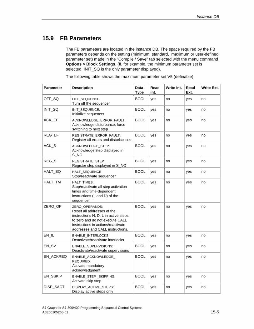
Instance DB
S7 Graph for S7-300/400 Programming Sequential Control SystemsA5E00105265-01 15-5
15.9 FB Parameters
The FB parameters are located in the instance DB. The space required by the FBparameters depends on the setting (minimum, standard, maximum or user-definedparameter set) made in the "Compile / Save" tab selected with the menu commandOptions > Block Settings. (If, for example, the minimum parameter set isselected, INIT_SQ is the only parameter displayed).
The following table shows the maximum parameter set V5 (definable).
Parameter Description DataType
Readint.
Write int. ReadExt.
Write Ext.
OFF_SQ OFF_SEQUENCE:Turn off the sequencer
BOOL yes no yes no
INIT_SQ INIT_SEQUENCE:Initialize sequencer
BOOL yes no yes no
ACK_EF ACKNOWLEDGE_ERROR_FAULT:Acknowledge disturbance, forceswitching to next step
BOOL yes no yes no
REG_EF REGISTRATE_ERROR_FAULT:Register all errors and disturbances
BOOL yes no yes no
ACK_S ACKNOWLEDGE_STEPAcknowledge step displayed inS_NO
BOOL yes no yes no
REG_S REGISTRATE_STEPRegister step displayed in S_NO
BOOL yes no yes no
HALT_SQ HALT_SEQUENCEStop/reactivate sequencer
BOOL yes no yes no
HALT_TM HALT_TIMES:Stop/reactivate all step activationtimes and time-dependentinstructions (L and D) of thesequencer
BOOL yes no yes no
ZERO_OP ZERO_OPERANDS:Reset all addresses of theinstructions N, D, L in active stepsto zero and do not execute CALLinstructions in actions/reactivateaddresses and CALL instructions.
BOOL yes no yes no
EN_IL ENABLE_INTERLOCKS:Deactivate/reactivate interlocks
BOOL yes no yes no
EN_SV ENABLE_SUPERVISIONS:Deactivate/reactivate supervisions
BOOL yes no yes no
EN_ACKREQ ENABLE_ACKNOWLEDGE_REQUIRED:Activate mandatoryacknowledgment
BOOL yes no yes no
EN_SSKIP ENABLE_STEP _SKIPPING:Activate skip step
BOOL yes no yes no
DISP_SACT DISPLAY_ACTIVE_STEPS:Display active steps only
BOOL yes no yes no
05.04.0105.04.200105.04.2001

Instance DB
S7 Graph for S7-300/400 Programming Sequential Control Systems15-6 A5E00105265-01
Parameter Description DataType
Readint.
Write int. ReadExt.
Write Ext.
DISP_SEF DISPLAY_STEPS_WITH_ERROR_OR_FAULT:Display steps with errors anddisturbed steps only
BOOL yes no yes no
DISP_SALL DISPLAY_ALL_STEPS:Display all steps
BOOL yes no yes no
S_PREV PREVIOUS_STEP:Automatic mode: Indicate previoussimultaneously active steps inS_NO Manual mode: Indicateprevious step (next lower number)
BOOL yes no yes no
S_NEXT NEXT_STEP:Automatic mode: Indicate nextsimultaneously active step in S_NOmanual mode: Indicate next step(next higher number)
BOOL yes no yes no
SW_AUTO SWITCH_MODE_AUTOMATIC:Mode changer: Automatic mode
BOOL yes no yes no
SW_TAP SWITCH_MODE_TRANSITION_AND_PUSH:Mode changer: Inching mode("semi-automatic")
BOOL yes no yes no
SW_TOP SWITCH_MODE_TRANSITION_OR_PUSH:Mode change:Automatic or switch to next
BOOL yes no yes no
SW_MAN SWITCH_MODE_MANUAL:Mode changer: Manual mode, notriggering of automatic execution
BOOL yes no yes no
S_SEL STEP_SELECT:Selects a specific step for the outputparameter S_NO.Activate/deactivate in the manualmode with S_ON, S_OFF.
INT yes no yes no
S_SELOK STEP_SELECT_OK:Use value in S_SEL for S_NO
BOOL yes no yes no
S_ON STEP_ON:Manual mode: Activate indicatedstep
BOOL yes no yes no
S_OFF STEP_OFF:Manual mode: Deactivate thedisplayed step
BOOL yes no yes no
T_PREV PREVIOUS_TRANSITION:Display previous valid transition inT_NO
BOOL yes no yes no
T_NEXT NEXT_TRANSITION:Display next valid transition in T_NO
BOOL yes no yes no
05.04.0105.04.200105.04.2001
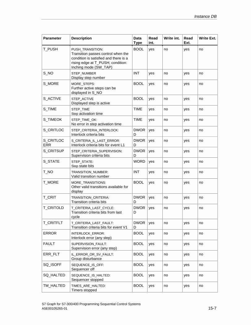
Instance DB
S7 Graph for S7-300/400 Programming Sequential Control SystemsA5E00105265-01 15-7
Parameter Description DataType
Readint.
Write int. ReadExt.
Write Ext.
T_PUSH PUSH_TRANSITION:Transition passes control when thecondition is satisfied and there is arising edge at T_PUSH; condition:Inching mode (SW_TAP)
BOOL yes no yes no
S_NO STEP_NUMBERDisplay step number
INT yes no yes no
S_MORE MORE_STEPS:Further active steps can bedisplayed in S_NO
BOOL yes no yes no
S_ACTIVE STEP_ACTIVEDisplayed step is active
BOOL yes no yes no
S_TIME STEP_TIMEStep activation time
TIME yes no yes no
S_TIMEOK STEP_TIME_OK:No error in step activation time
TIME yes no yes no
S_CRITLOC STEP_CRITERIA_INTERLOCK:Interlock criteria bits
DWORD
yes no yes no
S_CRITLOCERR
S_CRITERIA_IL_LAST_ERROR:Interlock criteria bits for event L1
DWORD
yes no yes no
S_CRITSUP STEP_CRITERIA_SUPERVISION:Supervision criteria bits
DWORD
yes no yes no
S_STATE STEP_STATE:Step state bits
WORD yes no yes no
T_NO TRANSITION_NUMBER:Valid transition number
INT yes no yes no
T_MORE MORE_TRANSITIONS:Other valid transitions available fordisplay
BOOL yes no yes no
T_CRIT TRANSITION_CRITERIA:Transition criteria bits
DWORD
yes no yes no
T_CRITOLD T_CRITERIA_LAST_CYCLE:Transition criteria bits from lastcycle
DWORD
yes no yes no
T_CRITFLT T_CRITERIA_LAST_FAULT:Transition criteria bits for event V1
DWORD
yes no yes no
ERROR INTERLOCK_ERROR:Interlock error (any step)
BOOL yes no yes no
FAULT SUPERVISION_FAULT:Supervision error (any step)
BOOL yes no yes no
ERR_FLT IL_ERROR_OR_SV_FAULT:Group disturbance
BOOL yes no yes no
SQ_ISOFF SEQUENCE_IS_OFF:Sequencer off
BOOL yes no yes no
SQ_HALTED SEQUENCE_IS_HALTED:Sequencer stopped
BOOL yes no yes no
TM_HALTED TIMES_ARE_HALTED:Timers stopped
BOOL yes no yes no
05.04.0105.04.200105.04.2001

Instance DB
S7 Graph for S7-300/400 Programming Sequential Control Systems15-8 A5E00105265-01
Parameter Description DataType
Readint.
Write int. ReadExt.
Write Ext.
OP_ZEROED OPERANDS_ARE_ZEROED:Addresses reset
BOOL yes no yes no
IL_ENABLED INTERLOCK_IS_ENABLED:Interlocks not deactivated
BOOL yes no yes no
SV_ENABLED SUPERVISION_IS_ENABLED:Supervisions not deactivated
BOOL yes no yes no
ACKREQ_ENABLED
ACKNOWLEDGE_REQUIRED_IS_ENABLED:Mandatory acknowledgmentactivated
BOOL yes no yes no
SSKIP_ENABLED
STEP_SKIPPING_IS_ENABLED:Skip step activated
BOOL yes no yes no
SACT_DISP ACTIVE_STEPS_WERE_DISPLAYEDDisplay list with active steps only
BOOL yes no yes no
SEF_DISP STEPS_WITH_ERROR_FAULT_WERE_DISPLAYED:Display list only with steps with errorand disturbed steps
BOOL yes no yes no
SALL_DISP ALL_STEPS_WERE_DISPLAYED:Display list with all steps
BOOL yes no yes no
AUTO_ON AUTOMATIC_IS_ON:Indicates the automatic mode
BOOL yes no yes no
TAP_ON T_AND_PUSH_IS_ON:Indicates the inching mode
BOOL yes no yes no
TOP_ON T_OR_PUSH_IS_ON:Display SW_TOP mode
BOOL yes no yes no
MAN_ON MANUAL_IS_ON:Indicates the manual mode
BOOL yes no yes no
05.04.0105.04.200105.04.2001

Instance DB
S7 Graph for S7-300/400 Programming Sequential Control SystemsA5E00105265-01 15-9
15.10 The Transition Structure
A structure with the following parameters is created in the instance DB for everytransition located in the sequencer of the S7 Graph FB:
Component Description DataType
Readint.
Write int. ReadExt.
Write Ext.
TV Transition is valid BOOL yes no yes no
TT Transition is satisfied BOOL yes no yes no
TS Transition switches BOOL yes no yes no
CF_IV The CRIT_FLT entry is invalid BOOL yes no yes no
TNO Indicates the user-defined transitionnumber
INT no no yes no
CRIT Status of the maximum 32LAD/FBD elements of the transitionin the current processing cycle
DWORD yes no yes no
CRIT_OLD Status of the maximum 32LAD/FBD elements of the transitionin the previous processing cycle
DWORD yes no yes no
CRIT_FLT Copy of CRIT if an error occurs DWORD yes no yes no
"Memory minimized" OptionIf you set the "Memory minimized" option, an array with the structures of the transitionsis created analogous to the "Structure fields" option. Only the Boolean components TV,TT, TS are stored as structure elements. The internal and external accesses are alsothe same as with the "Structure fields" option.
"Structure arrays" Option
If you have selected the "Structure arrays" option, an array containing thestructures of the transitions is created.
Array Name Length in Bytes
G7T (number of transitions) ∗ 16
Internal access uses the transition number followed by the name of the structuralelement.
This means that the following access is possible in conditions or actions:
• T003.TT
• T017.CRIT
05.04.0105.04.200105.04.2001
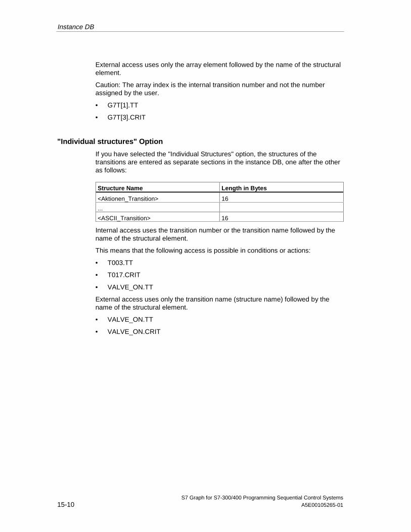
Instance DB
S7 Graph for S7-300/400 Programming Sequential Control Systems15-10 A5E00105265-01
External access uses only the array element followed by the name of the structuralelement.
Caution: The array index is the internal transition number and not the numberassigned by the user.
• G7T[1].TT
• G7T[3].CRIT
"Individual structures" Option
If you have selected the "Individual Structures" option, the structures of thetransitions are entered as separate sections in the instance DB, one after the otheras follows:
Structure Name Length in Bytes
<Aktionen_Transition> 16
...
<ASCII_Transition> 16
Internal access uses the transition number or the transition name followed by thename of the structural element.
This means that the following access is possible in conditions or actions:
• T003.TT
• T017.CRIT
• VALVE_ON.TT
External access uses only the transition name (structure name) followed by thename of the structural element.
• VALVE_ON.TT
• VALVE_ON.CRIT
05.04.0105.04.200105.04.2001

Instance DB
S7 Graph for S7-300/400 Programming Sequential Control SystemsA5E00105265-01 15-11
15.11 The Step Structure
A structure with the following components is created in the instance DB for everystep of the sequencer in the S7 Graph FB, as follows:
Component Description DataType
Readint.
Write int. ReadExt.
Write Ext.
S1 Step is activated BOOL yes no yes no
L1 interlock leaving state BOOL yes no yes no
V1 Supervision entering state BOOL yes no yes no
R1 Reserved BOOL no no no no
A1 Error is acknowledged BOOL yes no yes no
S0 Step is deactivated BOOL yes no yes no
L0 Interlock entering state BOOL yes no yes no
V0 Supervision leaving state BOOL yes no yes no
X Step is active BOOL yes no yes no
LA Interlock is not satisfied BOOL yes no yes no
VA Supervision active BOOL yes no yes no
RA Reserved BOOL no no no no
AA Reserved BOOL no no no no
SS System-internal BOOL no no no no
LS Direct result of the programmedinterlock
BOOL yes no yes no
VS Direct result of the programmedsupervision
BOOL yes no yes no
SNO User step number INT no no yes no
T Total step activation time TIME yes no yes no
U Step activation time withoutdisturbance
TIME yes no yes no
CRIT_LOC Status of the maximum 32 LAD/FBDelements in the interlock in thecurrent processing cycle
DWORD yes no yes no
CRIT_LOC_ERR
Copy of CRIT_LOC when theinterlock leaves the state
DWORD yes no yes no
CRIT_SUP Status of the maximum 32 LAD/FBDelements in the supervision in thecurrent processing cycle.
DWORD yes no yes no
SM System-internal BOOL no no no no
LP System-internal BOOL no no no no
LN System-internal BOOL no no no no
VP System-internal BOOL no no no no
VN System-internal BOOL no no no no
H_IL_ERR System-internal BYTE no no no no
H_SV_FLT System-internal BYTE no no no no
RESERVED Reserve DWORD no no no no
05.04.0105.04.200105.04.2001
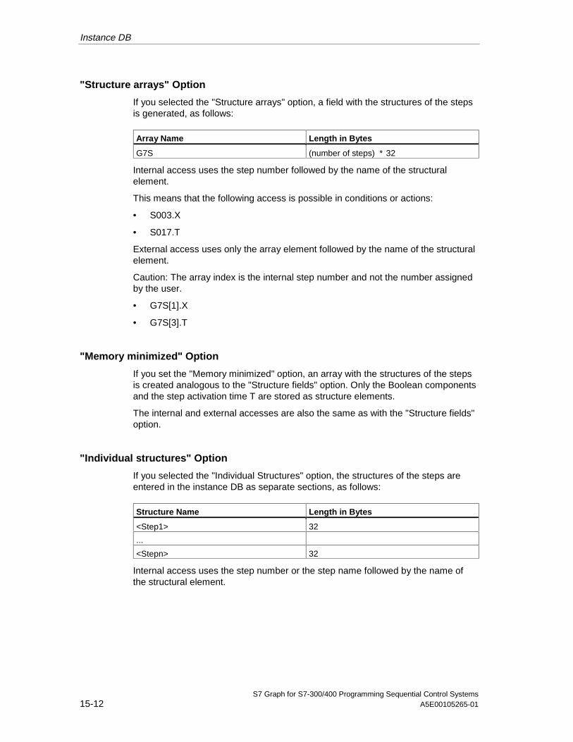
Instance DB
S7 Graph for S7-300/400 Programming Sequential Control Systems15-12 A5E00105265-01
"Structure arrays" Option
If you selected the "Structure arrays" option, a field with the structures of the stepsis generated, as follows:
Array Name Length in Bytes
G7S (number of steps) ∗ 32
Internal access uses the step number followed by the name of the structuralelement.
This means that the following access is possible in conditions or actions:
• S003.X
• S017.T
External access uses only the array element followed by the name of the structuralelement.
Caution: The array index is the internal step number and not the number assignedby the user.
• G7S[1].X
• G7S[3].T
"Memory minimized" Option
If you set the "Memory minimized" option, an array with the structures of the stepsis created analogous to the "Structure fields" option. Only the Boolean componentsand the step activation time T are stored as structure elements.
The internal and external accesses are also the same as with the "Structure fields"option.
"Individual structures" Option
If you selected the "Individual Structures" option, the structures of the steps areentered in the instance DB as separate sections, as follows:
Structure Name Length in Bytes
<Step1> 32
...
<Stepn> 32
Internal access uses the step number or the step name followed by the name ofthe structural element.
05.04.0105.04.200105.04.2001

Instance DB
S7 Graph for S7-300/400 Programming Sequential Control SystemsA5E00105265-01 15-13
This means that the following access is possible in conditions or actions:
• S003.X
• S017.T
• DRY.X
External access uses only the step name (structure name) followed by the name ofthe structural element, as follows:
• DRY.X
• DRY.T
15.12 Sequencer Status
The sequencer status area consists of several components (arrays or structures)containing information about the status of the sequencer, as follows:
• Permanent Instructions Component
• Index Arrays Component
• Mode Component (Mode of Operation, MOP)
• Activation Time Component
• Group Bits Component
The sequencer status area starts at the address: a = FB parameter length +transition array length(s)+step array length(s).
Permanent Instructions
This component of the sequencer status area describes the permanent instructionsthat can be programmed before or after the sequencer. The component is omittedif no permanent instructions are programmed.
Name Description Datatype
Length Readint.
Write int. ReadExt.
Write Ext.
PRE_CRIT Status of the permanentinstruction preceding thesequencer
DWORD 0 - n no no yes no
POST_CRIT Status of the permanentinstructions following thesequencer
DWORD 0 - n no no yes no
PRE_CNT Number of permanentinstructions preceding thesequencer
WORD no no yes no
POST_CNT Number of permanentinstructions after thesequencer
WORD no no yes no
05.04.0105.04.200105.04.2001

Instance DB
S7 Graph for S7-300/400 Programming Sequential Control Systems15-14 A5E00105265-01
Index Arrays
The first component of the sequencer status area contains the index arrays formanaging the internal step and transition numbers.
Index Name Description DataType
Length inBytes
Readint.
Write int. ReadExt.
WriteExt.
TVX Array of valid transitions BYTE <intern> no no yes no
TTX Array of satisfied transitions BYTE <intern> no no yes no
TSX Array of switching transitions BYTE <intern> no no yes no
S00X Array of steps to bedeactivated (second lastcycle)
BYTE <intern> no no no no
SOFFX Array_1 of the steps to bedeactivated
BYTE <intern> no no no no
SONX Array_1 of the steps to beactivated
BYTE <intern> no no no no
SAX Array of active steps BYTE <intern> no no yes no
SERRX Array of disturbed steps BYTE S_CNT+2 no no yes no
SMX Array of marked steps BYTE S_CNT+2 no no no no
S0X Array_2 of the steps to bedeactivated
BYTE S_CNT+2 no no no no
S1X Array_2 of the steps to beactivated
BYTE S_CNT+2 no no no no
S_DISPLAY Copy of the output parameterS_NO (can also be evaluatedif the minimum parameter setoption is selected)
INT 2 yes no yes no
S_SEL_OLD System-internal INT 2 no no no no
S_DISPIDX System-internal BYTE 1 no no no no
T_DISPIDX System-internal BYTE 1 no no no no
Length of the Index Arrays
The length of the index arrays TVX to S1X is obtained as follows:
l = (maximum number of elements) + 2
The index arrays are structured as follows:
Array[0] = Index of the first free position in the array
Array[1] - Array[n-2] = Entries
Array[n-1] = 0 (indicates the end of the array)
New entries are added at the end. When entries are removed, the array is shiftedtogether. This means that, for example, in the array of active steps (SAX), the stepthat is active longest has the lowest index.
05.04.0105.04.200105.04.2001
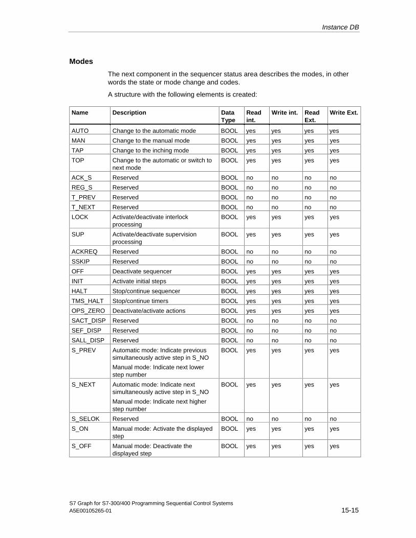
Instance DB
S7 Graph for S7-300/400 Programming Sequential Control SystemsA5E00105265-01 15-15
Modes
The next component in the sequencer status area describes the modes, in otherwords the state or mode change and codes.
A structure with the following elements is created:
Name Description DataType
Readint.
Write int. ReadExt.
Write Ext.
AUTO Change to the automatic mode BOOL yes yes yes yes
MAN Change to the manual mode BOOL yes yes yes yes
TAP Change to the inching mode BOOL yes yes yes yes
TOP Change to the automatic or switch tonext mode
BOOL yes yes yes yes
ACK_S Reserved BOOL no no no no
REG_S Reserved BOOL no no no no
T_PREV Reserved BOOL no no no no
T_NEXT Reserved BOOL no no no no
LOCK Activate/deactivate interlockprocessing
BOOL yes yes yes yes
SUP Activate/deactivate supervisionprocessing
BOOL yes yes yes yes
ACKREQ Reserved BOOL no no no no
SSKIP Reserved BOOL no no no no
OFF Deactivate sequencer BOOL yes yes yes yes
INIT Activate initial steps BOOL yes yes yes yes
HALT Stop/continue sequencer BOOL yes yes yes yes
TMS_HALT Stop/continue timers BOOL yes yes yes yes
OPS_ZERO Deactivate/activate actions BOOL yes yes yes yes
SACT_DISP Reserved BOOL no no no no
SEF_DISP Reserved BOOL no no no no
SALL_DISP Reserved BOOL no no no no
S_PREV Automatic mode: Indicate previoussimultaneously active step in S_NO
Manual mode: Indicate next lowerstep number
BOOL yes yes yes yes
S_NEXT Automatic mode: Indicate nextsimultaneously active step in S_NO
Manual mode: Indicate next higherstep number
BOOL yes yes yes yes
S_SELOK Reserved BOOL no no no no
S_ON Manual mode: Activate the displayedstep
BOOL yes yes yes yes
S_OFF Manual mode: Deactivate thedisplayed step
BOOL yes yes yes yes
05.04.0105.04.200105.04.2001
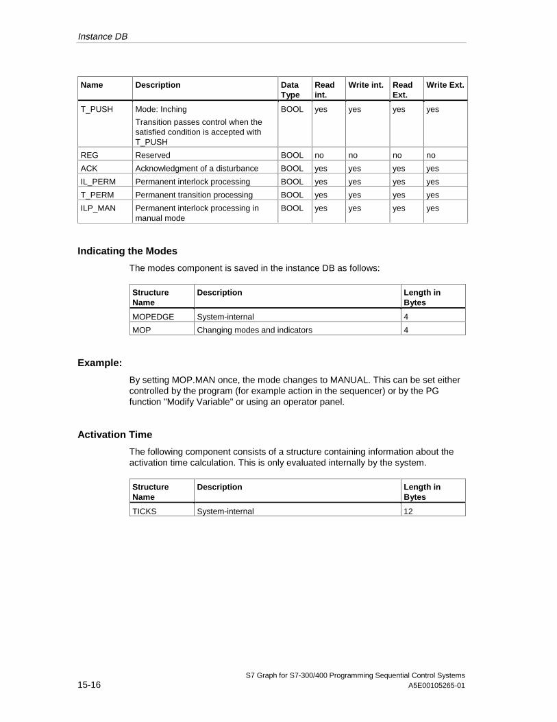
Instance DB
S7 Graph for S7-300/400 Programming Sequential Control Systems15-16 A5E00105265-01
Name Description DataType
Readint.
Write int. ReadExt.
Write Ext.
T_PUSH Mode: Inching
Transition passes control when thesatisfied condition is accepted withT_PUSH
BOOL yes yes yes yes
REG Reserved BOOL no no no no
ACK Acknowledgment of a disturbance BOOL yes yes yes yes
IL_PERM Permanent interlock processing BOOL yes yes yes yes
T_PERM Permanent transition processing BOOL yes yes yes yes
ILP_MAN Permanent interlock processing inmanual mode
BOOL yes yes yes yes
Indicating the Modes
The modes component is saved in the instance DB as follows:
StructureName
Description Length inBytes
MOPEDGE System-internal 4
MOP Changing modes and indicators 4
Example:
By setting MOP.MAN once, the mode changes to MANUAL. This can be set eithercontrolled by the program (for example action in the sequencer) or by the PGfunction "Modify Variable" or using an operator panel.
Activation Time
The following component consists of a structure containing information about theactivation time calculation. This is only evaluated internally by the system.
StructureName
Description Length inBytes
TICKS System-internal 12
05.04.0105.04.200105.04.2001
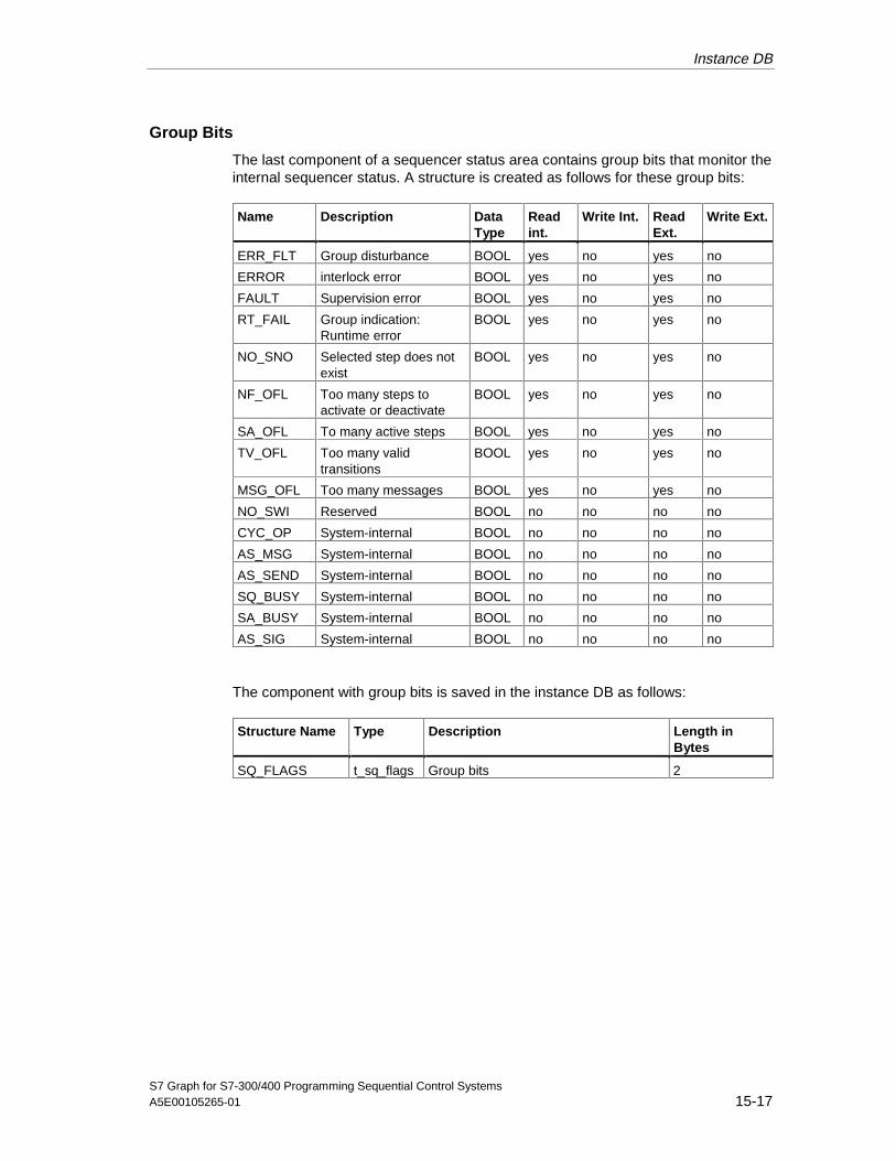
Instance DB
S7 Graph for S7-300/400 Programming Sequential Control SystemsA5E00105265-01 15-17
Group Bits
The last component of a sequencer status area contains group bits that monitor theinternal sequencer status. A structure is created as follows for these group bits:
Name Description DataType
Readint.
Write Int. ReadExt.
Write Ext.
ERR_FLT Group disturbance BOOL yes no yes no
ERROR interlock error BOOL yes no yes no
FAULT Supervision error BOOL yes no yes no
RT_FAIL Group indication:Runtime error
BOOL yes no yes no
NO_SNO Selected step does notexist
BOOL yes no yes no
NF_OFL Too many steps toactivate or deactivate
BOOL yes no yes no
SA_OFL To many active steps BOOL yes no yes no
TV_OFL Too many validtransitions
BOOL yes no yes no
MSG_OFL Too many messages BOOL yes no yes no
NO_SWI Reserved BOOL no no no no
CYC_OP System-internal BOOL no no no no
AS_MSG System-internal BOOL no no no no
AS_SEND System-internal BOOL no no no no
SQ_BUSY System-internal BOOL no no no no
SA_BUSY System-internal BOOL no no no no
AS_SIG System-internal BOOL no no no no
The component with group bits is saved in the instance DB as follows:
Structure Name Type Description Length inBytes
SQ_FLAGS t_sq_flags Group bits 2
05.04.0105.04.200105.04.2001

Instance DB
S7 Graph for S7-300/400 Programming Sequential Control Systems15-18 A5E00105265-01
15.13 Internal Data Area
This part of the instance DB is a system-internal area. These data should not beaccessed. The data area is divided into 4 sections:
Internal Working Area 1
Description Data Length
Internal Working Area 1 Variable Variable
Condition Descriptions
These data are only entered when you select the option "With Data".
Address Description Data Length
ADR_LOG_T[]:Descriptions for all transitions with content; thestart addresses are in the field ADR_LOG_T[]; a0 is entered here for empty transitions and thereis no description.
LOG_Ti[]
LOG_Tj[]
...
LOG_Tk[]
This is possibly followed by padding bytes withthe value 0 at the end of LOG_Tx so that thefollowing fields start at an even address.
BYTE[]
BYTE[]
...
BYTE[]
ADR_LOG_L[]:Descriptions of all interlock conditions withcontents; the start addresses are in the fieldADR_LOG_L[]; here, a 0 is entered for emptyinterlocks and there is no description.
LOG_Lp[]
LOG_Lq[]
...
LOG_Lr[]
This is possibly followed by padding bytes withthe value 0 at the end of LOG_Ly, so that thefollowing fields start with an even address
BYTE[]
BYTE[]
...
BYTE[]
c∗S_CNT-2∗T_CNT
ADR_LOG_T:Addresses of the transition descriptions LOG_TxADR_LOG_T[0...T_CNT]
WORD[] (T_CNT+1)∗2
c+2∗T_CNT+2
ADR_LOG_L:Addresses of the interlocks LOG_LyADR_LOG_L[0...S_CNT]
WORD[] (S_CNT+1)∗2
c+2∗T_CNT+2∗S_CNT+4
ADR_T1_CRITFLT:Address of disturbed transition criteria of T1ADR_T1_CRITFLT ==address(G7T[1].CRIT_FLT)
WORD 2
05.04.0105.04.200105.04.2001

Instance DB
S7 Graph for S7-300/400 Programming Sequential Control SystemsA5E00105265-01 15-19
Address Description Data Length
c+2∗T_CNT+2∗S_CNT+6
ADR_S1_CRITERR:Address of the disturbed interlock criteria of S1ADR_S1_CRITERR ==address(G7S[1].CRIT_ERR)
WORD 2
c+2∗T_CNT+2∗S_CNT+8
ADR_SERRX:Address of the array of disturbed steps SERRX[]ADR_SERRX == address(SERRX[0]) == e
WORD 2
n = Length of the instance DB in bytes
Internal Work Area 2
Description Data Length
Internal Work Area 2 Variable Variable
Numeric Data of the Sequencer
Address Description Data Length
n-36 ADR_COND:Address for the end of the conditiondescriptionsADR_COND ==Address(ADR_LOG_T[0]) == c
WORD 2
n-34 MAX_TVAL:Max. number of simultaneously validtransitions
BYTE 1
n-33 MAX_SACT:Max. number of simultaneously activesteps
BYTE 1
n-32 MAX_CRIT:Max. number of criteria per condition
BYTE 1
n-31 T_CNTNumber of transitions
BYTE 1
n-30 SUP_CNT:Number of supervisions
BYTE 1
n-29 LOCK_CNT:Number of interlocks
BYTE 1
n-28 S_CNTNumber of steps
BYTE 1
n-27 SQ_CNT:Number of branch paths
BYTE 1
n-26 PRS_INPAR:Range of input parameters
DWORD 1
n-22 PRS_OUTPAR:Range of output parameters
DWORD 1
n-18 SQ_FLAGSCompiler flags part 1
WORD 6
05.04.0105.04.200105.04.2001

Instance DB
S7 Graph for S7-300/400 Programming Sequential Control Systems15-20 A5E00105265-01
Address Description Data Length
n-6 SQ_FLAGSCompiler flags part 2
Bit .0 == 1 --> condition descriptionsexist
BYTE 1
n-5 SQ_FLAGSCompiler flags part 3
BYTE 1
n-4 G7_FBMARK:Compatibility FB criteria analysis
(010 == 1.0)
BYTE 1
n-3 G7_RELEASE:Graph version number (010 == 1.0)
BYTE 1
n-2 G7_ID2:Graph ID ("7")
BYTE 1
n-1 G7_ID1:Graph ID ("G")
BYTE 1
n = Length of the instance DB in bytes
05.04.0105.04.200105.04.2001

S7 Graph for S7-300/400 Programming Sequential Control SystemsA5E00105265-01 Glossary-1
Glossary
--A--
Action
An action is an instruction to execute a function in an active step.
--C--
Checkpoint
A checkpoint is a point in the program cycle at which plant or process states can beinfluenced or queried. There are various checkpoints, for example
• System checkpoint
• User checkpoint
Criteria analysis
Criteria analysis is a software program for S7 Graph, consisting of a criteria FB andextended instance DB. Criteria analysis detects and influences plant and processstates of S7 Graph sequential control systems.
--D--
Deactivate
Deactivating means that the step is terminated by the relevant transition or byanother step.
05.04.0105.04.200105.04.2001
Glossary
S7 Graph for S7-300/400 Programming Sequential Control SystemsGlossary-2 A5E00105265-01
--E--
Edge evaluation
Edge evaluation is required to detect and evaluate the change in a signal state.
The term edge is used when a signal state (for example of an input) changes. Arising edge means that the signal changes from state "0" to state "1". In theopposite situation, there is a falling edge.
Execution time
The execution time of an instruction is the time during which the instruction isactive; in other words, executed.
--I--
Interlock
An interlock is a programmed condition within a step. An interlock influences theexecution of individual actions.
--L--
LAD branch
The LAD branch corresponds to an OR logic operation on elements in a transition,interlock, or supervision.
--N--
Normally-open contact/normally-closed contact
Normally-open contacts and normally-closed contacts are bit logic operations. Theycan be used as elements in transitions, supervisions, or interlocks.
• The normally-open contact switches when the Boolean address is set.
• The normally-closed contact switches when the Boolean address is not set.
05.04.0105.04.200105.04.2001

Glossary
S7 Graph for S7-300/400 Programming Sequential Control SystemsA5E00105265-01 Glossary-3
--P--
Path in an alternative branch
A path in an alternative branch is the divergence of a sequencer to a specific stepdependent on several parallel transitions.
Process image
A memory area on the CPU in which the status of the inputs and outputs isentered.
1. Process image input table (PII): PII
2. Process image output table (PIQ): PIQ.
Processing time
The processing time is the time taken by the CPU to process an instruction (action,condition) and is usually in the ms range per instruction.
--S--
Sequencers
A sequencer is the heart of a sequential control system. Here, the program forsequential control is created and processed.
The sequencer consists of a series of steps whose execution is started in aspecified dependent on step enabling conditions.
Sequential control system
A control system in which control is passed sequentially from one step to the nextaccording to the program dependent on conditions.
Step
The control task is divided into single steps. Actions are formulated in the stepsthat are executed by the controller in a certain status (for example for controllingthe outputs or activating and deactivating steps).
Step comment
The step comment is a text in a step with a maximum of 2048 characters.
Start point
The start point is the defined start of the program cycle. When the program starts,the process image input table (PII) is read, effectively querying the plant or processstate.
05.04.0105.04.200105.04.2001
Glossary
S7 Graph for S7-300/400 Programming Sequential Control SystemsGlossary-4 A5E00105265-01
Status
The status is the signal state of the bits of an address on the PLC.
Status display
The status display is the display of the signal state of an address on the monitor ofa programming device/PC connected online with the PLC.
Step enabling condition
Step enabling conditions are Boolean logic operations that specify the conditionsfor terminating the predecessor step and activating the successor step.
They are components of the transitions.
Structural element
Structural elements are jumps and transitions in a sequencer.
Supervision
A supervision is a programmable condition within a step. A supervision influencesthe way in which control passes from one step to the next.
System checkpoint
The system checkpoint is the interface between the system and the user program.At the system control point, you can monitor or modify the signal states of theprocess variables and set the signal states at outputs from the programmingdevice.
--T--
Transition
A transition is the part of the sequencer that contains the conditions for passingcontrol from one step to its successor step.
A valid transition is a transition whose predecessor step or steps are active.
When a transition is valid and its step enabling conditions are satisfied, controlpasses to the successor step. The predecessor step is then deactivated and thesuccessor step is activated.
05.04.0105.04.200105.04.2001

Glossary
S7 Graph for S7-300/400 Programming Sequential Control SystemsA5E00105265-01 Glossary-5
--U--
User checkpoint
The user checkpoint is a selectable point in the user program for displaying thesignal states of variables.
User program
The user program contains all the blocks and instructions of the program.
05.04.0105.04.200105.04.2001

Glossary
S7 Graph for S7-300/400 Programming Sequential Control SystemsGlossary-6 A5E00105265-01
05.04.0105.04.200105.04.2001

S7 Graph for S7-300/400 Programming Sequential Control SystemsA5E00105265-01 Index-1
Index
AAbort situations ............................................14-9Accessing the instance DB...........................15-4Actions ........................ 7-3, 13-10, 13-11, 13-12,
.................. 13-13, 13-14, 13-22, 13-23, 13-24components ..............................................7-3overview of arithmetic.............................13-22overview of counters ..............................13-10overview of timers ..................................13-16
Activation time............................................15-16Activation time of steps ................................7-25Active step......................................................6-2Alternative branch ..........................................6-7Areas.....................................................7-1, 7-14
for actions and conditions...........................7-1for conditions............................................7-14
Arithmetic in actions ..........................7-11, 13-22Assignment of instance DB and
S7 Graph FB ............................................15-2Assignments with Built-in function................7-12Assignments with operator ...........................7-13Authorization ...........................................2-1, 2-2
loss ............................................................2-2Automatic creation of the instance DB
on saving..................................................15-3Automatic mode ...........................................9-10Automatic mode (SW_AUTO) ......................9-11Automatic mode or switch to next.................9-10Automatic or switch to next mode
(SW_TOP)................................................9-14Automatically compiling on saving an
S7 Graph FB ............................................8-15
BBit logic operations.......................................7-20Block ......................................... 10-1, 10-2, 10-3
from PG....................................................10-1uplading to the PG from the CPU.............10-3
Block comment.............................................6-11Branch stop ....................................................6-9
CCalling the S7 Graph FB .........................9-1, 9-2Comment......................................................7-28Compiling .....................................................8-15
compiling an S7 Graph source file............8-15saving and compiling..................................8-1sequencers ....................................8-14, 8-15
Condition ..................................................... 7-18programming with Ladder Logic
elements .............................................. 7-18Conditions.................................. 7-14, 7-22, 7-25
Programming with FBD elements ............ 7-22specific to S7 Graph ................................ 7-25
Control sequencer ....................................... 11-4Copy protection.............................................. 2-1Counters in actions ............................. 7-9, 13-10Creating a symbol table ................................. 3-9Creating an S7 Graph FB and
programminga sequencer ............................................. 3-10
Creating diagnostic data ............................ 14-13Creating messages.................................... 14-13Creating the drill project in the SIMATIC
Manager..................................................... 3-8Creating the instance DB later ..................... 15-3Creating the project in the
SIMATIC Manager ..................................... 5-1Customizing a display level ......................... 4-10Customizing colors and fonts....................... 4-11
DDefault setting of a display level .................... 4-9Defining the system signals ........................... 3-7Details window............................................... 4-5Direct assignments ...................................... 7-11Direct editing mode...................................... 4-14Display and position of the toolbars ............. 4-13Displaying and printing the content of the
instance DB ............................................. 15-3Displaying reference data ............................ 11-7Downloading blocks from the programming
device to the CPU.................................... 10-1Downloading the program to the CPU and
testing the sequencer .............................. 3-20Drag-and-Drop editing mode ....................... 4-14
EEditing the sequencer with the toolbars ....... 4-14Editing variables .......................................... 7-30Elements of a sequencer ............................... 6-5Eliminating Errors after Compilation
or after the Consistency Check................ 8-16Empty interlock ............................................ 7-16Empty steps ................................................. 7-3Empty transition ........................................... 7-15Enabling operation....................................... 14-4Entering FBD elements................................ 7-23
05.04.0105.04.200105.04.2001
Index
S7 Graph for S7-300/400 Programming Sequential Control SystemsIndex-2 A5E00105265-01
Entering Ladder Logic elements .................. 7-19Error
displaying ............................................... 4-15Evaluating the CPU messages .................... 11-6Evaluating the diagnostic buffer................... 11-6Event-dependent actions ............................. 13-2Event-dependent actions - to activate and
deactivate steps ......................................... 7-8Event-dependent actions - with and
without interlock ....................................... 13-2Event-dependent actions - with and
without Interlock ......................................... 7-7Examples ....................................................... 7-4Extended name............................................ 7-28
FFB parameters ...................................... 9-3, 15-5FBD elements ..................................... 7-22, 7-23FC70/FC71/FC72/FC73...............8-7, 8-11, 8-13Functional diagram...................................... 3-4
GGenerating and updating diagnostic data .... 11-7Group bits .................................................. 15-17
HHandling modes........................................... 14-5Handling supervision errors ......................... 7-26Handling the interlocks and manual
control in the manual mode...................... 14-7
IInching mode ............................................... 9-10Inching mode (SW_TAP) ............................. 9-13Including the sequencer in the
STEP 7 program ...................................... 3-18Index arrays ............................................... 15-14Indicating the modes.................................. 15-16Individual structures ..................................... 15-1Initial counter value ........................................ 7-9Initial step....................................................... 6-5Initialization .................................................. 14-8Input parameters of the S7 Graph FB............ 9-6Insert mode.................................................. 7-19
direct ........................................................ 7-19drag-and-drop .......................................... 7-19
Installation............................................. 2-9, 2-10Installation requirements................................ 2-8Installing S7 Graph ........................................ 2-8Installing the authorization ......................... 2-3Instance DB ............10-1, 10-2, 15-1, 15-2, 15-3,
...........15-4, 15-9, 15-10, 15-11, 15-12, 15-13,
..............................15-15, 15-18, 15-19, 15-20accessing................................................. 15-4automatic ................................................. 10-1displaying contents .................................. 15-3
including with FB ......................................15-3interface description .................................15-1internal working area ...........................15-18modes.....................................................15-15outline of the structure ..............................15-4printing......................................................15-3sequencer status ....................................15-13step structure..........................................15-11Transition structure...................................15-9
Interlock........................................................7-16Interlocks ......................................................14-8Internal data area .......................................15-18
of the instance DB ..................................15-18Introduction...................................................14-1
JJump...............................................................6-6
LLAD elements..................................... 7-19, 7-20
inserting ..................................................7-19logic operations ........................................7-20
Ladder Logic elements .................................7-18Ladder Logic elements for programming
conditions .................................................7-18Length of the index arrays ..........................15-14Level structure based on the example of a
manufacturing cell ....................................14-2Linking to operator control and monitoring
systems ..................................................14-12Logic operations with FBD elements ............7-24Logic operations with Ladder Logic
elements...................................................7-20
MMandatory acknowledgment.........................7-26Manual mode............................. 9-10, 9-12, 9-13Manual mode (SW_MAN).............................9-12Maximum parameter set...............................15-5memory requirements......................... 8-11, 8-12Menu bar ........................................................4-3Mode ..........................................................15-15
automatic or switch to next ...................9-15in the instance DB ..................................15-15inching ............................................ 9-13, 9-14manual............................................ 9-12, 9-13sequential control system .........................9-10
Modes...........9-10, 9-11, 9-12, 9-13, 9-14, 15-15automatic........................................ 9-11, 9-12
Modifications during installation andcommissioning........................................14-10
Modifying the sequencer ..............................3-22Monitoring.....................................................11-6Monitoring and modifying variables ..............11-6Monitoring and testing the sequential
control system ..........................................11-1Monitoring functions .....................................3-15
05.04.0105.04.200105.04.2001

Index
S7 Graph for S7-300/400 Programming Sequential Control SystemsA5E00105265-01 Index-3
programming ............................................3-15Monitoring the status information .................11-2
NName...................................................7-28, 7-29Navigating in the sequencer.........................4-15New sequencer ..............................................6-9Number ...............................................7-28, 7-29
OOB1..............................................................3-18Opening an S7 Graph FB or an S7 Graph
source file...................................................5-4Operating mode
selecting ..........................................9-10, 9-11Outline of the structure of the instance DB...15-4Output parameters of the S7 Graph FB..........9-9Overview of S7 Graph ....................................1-1Overview window ...........................................4-4
PParameter sets of the FB ...............................9-4Parameters..........................................7-30, 15-5
inserting in a sequencer ...........................7-30of the S7 Graph FB ..................................15-5
Permanent instructions................ 4-9, 6-10, 7-17Permanent Instructions ..............................15-13Printing the sequencer .................................12-1Printout.........................................................12-1Procedure for creating a sequential
control system ............................................3-2Programming actions and cnditions ...............7-1Programming conditions and actions .............7-1Programming monitoring functions...............3-15Programming step actions............................3-12Programming the structure of a sequencer ....6-1Programming transitions ..............................3-13Programming with symbolic addresses ........7-29Progressing ..................................................9-16
progressing with T_PUSH ........................9-16Project ............................................................5-1
creating in the SIMATIC Manager ..............5-1
QQuerying module information and the
operating mode ........................................11-6
RRepresenting the mode in the sequencer.....14-6Requirements........................................3-2, 7-26
for signaling and acknowledging ..............7-26Right of use ....................................................2-1Rules
for creating an S7 Graph FB ......................5-3for creating an S7 Graph source file...........5-3
for entering FBD elements ....................... 7-23for handling authorizations......................... 2-6for inserting LAD elements....................... 7-19for saving an S7 Graph FB ........................ 8-2for saving an S7 Graph source file............. 8-2for saving and compiling ............................ 8-1for the structure of a sequencer ................. 6-4
Running a consistency check ...................... 8-15
SS7 Graph
installing..................................................... 2-8starting...................................................... 4-1uninstalling............................................... 2-10user interface ............................................. 4-2
S7 Graph addresses in conditions ............... 7-25S7 Graph FB
creating..........................................3-10, 3-12input parameters........................................ 9-6output parameters...................................... 9-9S7 Graph FB.............................................. 5-3
S7 Graph FB or S7 Graph source file? .......... 5-2S7 Graph source file ...................................... 5-3Saving...................................3-17, 8-2, 8-3, 8-14
calculating memory requirements ............ 8-11saving an S7 Graph FB or an S7 Graph
source file ............................................ 8-14saving and closing the sequencer............ 3-17saving and compiling ................................. 8-1settings for saving and compiling............... 8-3
Search function............................................ 4-15Selecting a step with S_PREV or S_NEXT:. 9-15Selecting a step with S_SEL:....................... 9-15Selecting an FB parameter set ...................... 9-3Selecting the structure of the sequencer ....... 3-5Sequencer ................3-5, 3-10, 3-11, 3-12, 3-17,
................ 3-18, 3-20, 3-22, 3-23, 6-2, 6-3, 6-5creating.................................................... 3-10including in the STEP 7 program ............. 3-18modifying................................................ 3-22navigating ................................................ 4-15principle ..................................................... 6-2saving and closing ................................... 3-17selecting the structure................................ 3-5structures ................................................. 6-3testing ..................................................... 3-20
Sequencer status......15-13, 15-14, 15-15, 15-16activation time........................................ 15-16index arrays ........................................... 15-14modes.................................................... 15-15permanent instructions .......................... 15-13
Sequential control system............................ 9-10automatic mode ....................................... 9-10inching mode ........................................... 9-10manual mode ........................................... 9-10normal mode............................................ 9-10
Setting a display level .................................... 4-9Settings for printing...................................... 12-1Settings for the instance DB ........................ 15-1Settings for the mnemonics ......................... 13-1
05.04.0105.04.200105.04.2001
Index
S7 Graph for S7-300/400 Programming Sequential Control SystemsIndex-4 A5E00105265-01
Settings for the work area .............................. 4-8Settings in the "Compile/Save" tab
Executability............................................... 8-7FB Parameters........................................... 8-6sequencer properties ................................. 8-9
Settings in the "Compile/Save" Tabinterface description................................... 8-8Warnings.................................................. 8-10
Settings in the "General" tab.......................... 8-4Settings in the "Messages" tab .................... 8-10Simultaneous branch ..................................... 6-8Single step display......................................... 4-8Size of the machine code............................. 8-11Specifying the program structure and
incorporating the sequencer .................... 14-3Specifying the standard function block......... 3-16Standard actions..........................................7-4Standard actions with and
without interlock ....................................... 13-1Standard actions: ......................................... 13-1Standard function blocks
FC70FC71
FC72FC73 ..................................... 8-7, 8-13
specifying (drill example) ......................... 3-16Starting S7 Graph .......................................... 4-1Starting the installation program .................... 2-9Status bar ...................................................... 4-6Status display for steps and conditions........ 11-3Status display for the signal state of
addresses ................................................ 11-3Step .....................6-2, 7-15, 15-11, 15-12, 15-13
skipping .................................................. 7-15STEP 7 test functions .................................. 11-5Step actions ................................................. 3-12
programming............................................ 3-12Step description in the instance DB ........... 15-11Step structure ............................................ 15-11Steps in creating a project ............................. 5-1Steps/transitions ............................................ 6-5Step-transition pair......................................... 6-5Structure arrays ........................................... 15-1Structure of an instance DB ......................... 15-4Structures of a sequencer.............................. 6-3Supervision .................................................. 7-17Supervision errors........................................ 7-26Supervision errors and mandatory
acknowledgment ...................................... 7-26Supervisions ....................................... 14-8, 14-9SW_AUTO ................................................... 9-11SW_MAN ..................................................... 9-11SW_TAP ...................................................... 9-11SW_TOP...................................................... 9-11Symbol table .................................................. 3-9Synchronization ..............11-4, 11-5, 14-9, 14-10System signals
defining .....................................................3-7
TTechnological task and functional diagram.....3-3Test function.................................................3-21
control sequencer.....................................3-21Test functions ............................ 11-1, 11-2, 11-5
in STEP 7 .................................................11-5Monitoring and testing the sequential
control system ......................................11-1The modes of the sequential
control system ..........................................9-10Time constant.................................................7-5Timers ..........................................................7-25
actions ................. 13-16, 13-17, 13-18, 13-19,................................................13-20, 13-21
activation time of steps .............................7-25in actions ..................................................7-10timers in Actions .....................................13-16timers in conditions...................................7-25
Title bar ..........................................................4-3Toolbars ............................................... 4-3, 4-13
displaying................................................4-13position .....................................................4-13
Transition.............................................. 3-13, 6-5description in the instance DB ..................15-9programming ............................................3-14Step-transition pair and initial step .............6-5
Transition structure.......................................15-9
UUninstalling S7 Graph ..................................2-10Uninstalling the authorization ................. 2-3, 2-5Upgrading the authorization ...........................2-4Uploading blocks from the CPU to the
programming device.................................10-3User interface .................................................4-2Using standard function blocks FC70 FC71
FC72 and FC73........................................8-13
VVariables ......................................................7-30
WWhat’s new?...................................................1-4Work area.......................................................4-8Working area ..................................................4-3
ZZoom ............................................................4-10
05.04.2001