preliminary analysis of process flow sheet …
TRANSCRIPT
Distillation Absorption 2010 A.B. de Haan, H. Kooijman and A. Górak (Editors) All rights reserved by authors as per DA2010 copyright notice
187
PRELIMINARY ANALYSIS OF PROCESS FLOW SHEET MODIFICATIONS FOR ENERGY EFFICIENT CO2 CAPTURE FROM FLUE GASES USING CHEMICAL ABSORPTION Ashleigh Cousins1, Leigh T. Wardhaugh2 and Paul H.M. Feron2 1 CSIRO Energy Technology, P.O. Box 883, Kenmore, QLD 4069, Australia, Email: [email protected] 2 CSIRO Energy Technology, P.O. Box 330, Newcastle, NSW 2300, Australia
Abstract The energy penalty associated with solvent based capture of CO2 from power station flue gases can be reduced by incorporating process flow sheet modifications into the standard process. A review of modifications suggested in the open and patent literature identified several options, primarily intended for use in the gas processing industry. It was not immediately clear whether these options would have the same benefits when applied to CO2 capture from near atmospheric pressure flue gases. Process flow sheet modifications, including split flow, rich split, vapour recompression, and inter-stage cooling, were therefore modelled using a commercial rate-based simulation package. The preliminary modelling results showed considerable benefits in reducing the energy penalty of capturing CO2 from combustion flue gases. Further work will focus on optimising and validating the most relevant process flow sheet modifications in a pilot plant. Keywords: Post-combustion carbon capture, PCC, Carbon dioxide, CO2, Carbon capture and storage.
1. Introduction The CSIRO has designed and constructed three pilot plants within Australia for assessing the capture of CO2 from existing brown and black coal fired power stations using chemical absorption. The most recent pilot plant, based in Queensland, has been designed to be as flexible as possible to allow testing of various process flow sheet modifications. One of the major stumbling blocks for the commercial application of CO2 capture into power stations is the relatively large energy penalty imposed by the Post-Combustion Capture (PCC) process. The energy required to regenerate the solvent and run the PCC process is equivalent to a reduction in the thermal efficiency of the power station of about 20% (from roughly 44.0 to 35.3%, LHV) when capturing around 90% of the CO2
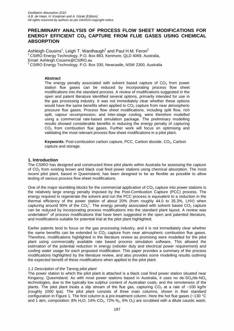
1. The energy penalty associated with solvent based CO2 capture can be reduced by incorporating process modifications into the standard plant layout. A review was undertaken2 of process modifications that have been suggested in the open and patented literature, and modifications suitable for potential trial at the pilot plant highlighted. Earlier patents tend to focus on the gas processing industry, and it is not immediately clear whether the same benefits can be extended to CO2 capture from near atmospheric combustion flue gases. Therefore, modifications highlighted in the literature review as promising were modelled for the pilot plant using commercially available rate based process simulation software. This allowed the estimation of the potential reduction in energy (reboiler duty and electrical power requirement) and cooling water usage for each proposed modification. This paper provides a summary of the process modifications highlighted by the literature review, and also provides some modelling results outlining the expected benefit of these modifications when applied to the pilot plant. 1.1 Description of the Tarong pilot plant The power station to which the pilot plant is attached is a black coal fired power station situated near Kingaroy, Queensland. As with most power stations based in Australia, it uses no de-SOx/de-NOx technologies, due to the typically low sulphur content of Australian coals, and the remoteness of the plants. The pilot plant treats a slip stream of the flue gas, capturing CO2 at a rate of ~100 kg/hr (roughly 1000 tpa). The pilot plant consists of three main columns, shown in their standard configuration in Figure 1. The first column is a pre-treatment column. Here the hot flue gases (~130 °C and 1 atm, composition: 8% H2O, 14% CO2, 72% N2, 6% O2) are scrubbed with a dilute caustic wash,
A. Cousins et.al.
188
cooling the flue gases (to ~45 °C) and reducing the SOx/NOx and particulate matter content. The cooled flue gases then enter the absorber column where they are contacted with an amine solvent (typically 30 wt% MEA) in order to capture the CO2. The absorber column contains 7m of Sulzer Mellapak M250X structured packing separated into four sections. This allows gas and liquid samples to be collected between packed sections and allows the inclusion of process modifications such as inter-stage cooling and split flow processes as described below. The CO2 lean flue gas passes into a water wash section at the top of the absorber column to remove any traces of solvent carried over in the gas stream. The CO2 laden solvent enters the stripping column for regeneration and separation of the CO2. The stripping column contains 7m of Sulzer Mellapak M350X structured packing separated into 2 sections, again allowing the collection of liquid samples and addition of process modifications. Hot gases leaving the stripping section enter the condenser section at the top of the column (1m of Sulzer Mellapak M350X structured packing). Lean solvent leaving the bottom of the stripping column is cooled and recycled to the absorption column.
Figure 1. Process Flow Diagram of the CO2 capture pilot plant
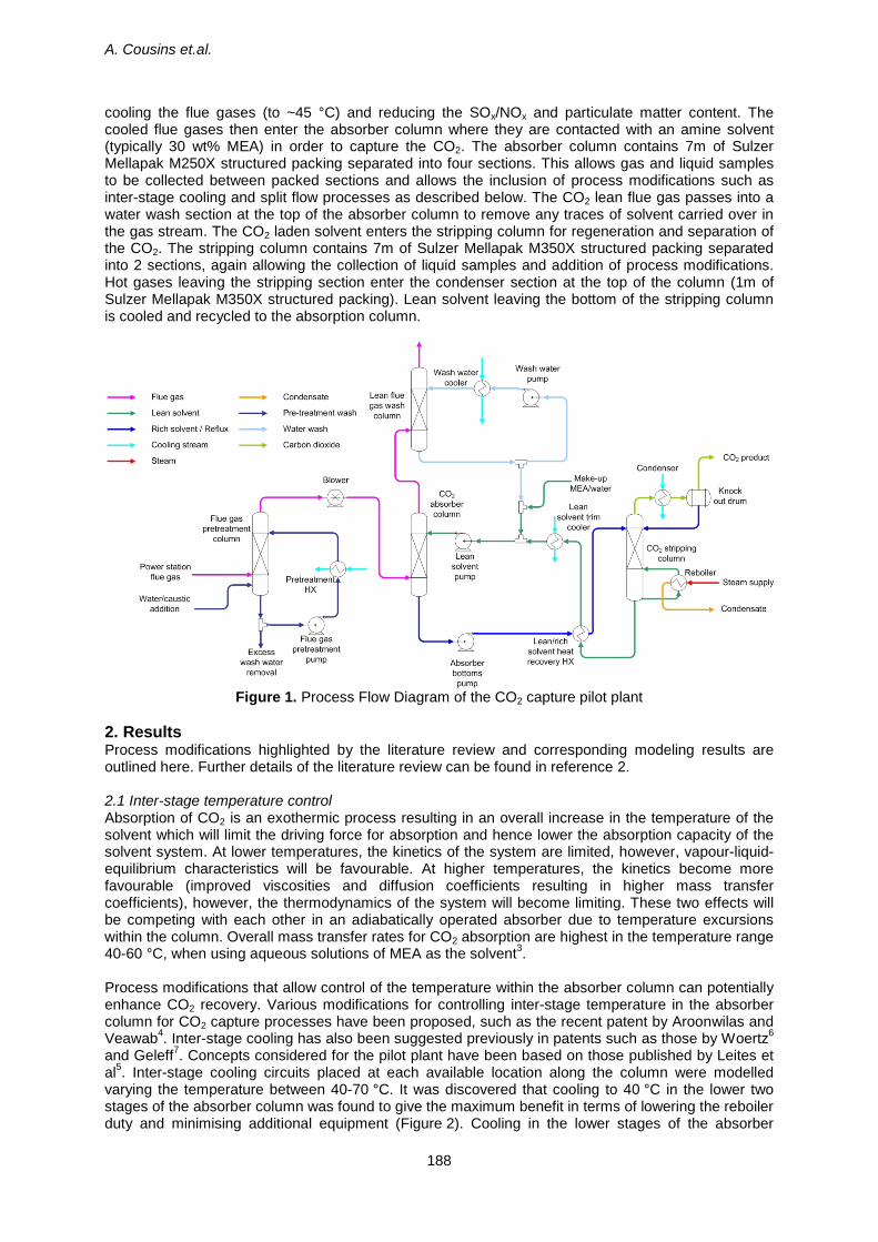
2. Results Process modifications highlighted by the literature review and corresponding modeling results are outlined here. Further details of the literature review can be found in reference 2. 2.1 Inter-stage temperature control Absorption of CO2 is an exothermic process resulting in an overall increase in the temperature of the solvent which will limit the driving force for absorption and hence lower the absorption capacity of the solvent system. At lower temperatures, the kinetics of the system are limited, however, vapour-liquid-equilibrium characteristics will be favourable. At higher temperatures, the kinetics become more favourable (improved viscosities and diffusion coefficients resulting in higher mass transfer coefficients), however, the thermodynamics of the system will become limiting. These two effects will be competing with each other in an adiabatically operated absorber due to temperature excursions within the column. Overall mass transfer rates for CO2 absorption are highest in the temperature range 40-60 °C, when using aqueous solutions of MEA as the solvent3. Process modifications that allow control of the temperature within the absorber column can potentially enhance CO2 recovery. Various modifications for controlling inter-stage temperature in the absorber column for CO2 capture processes have been proposed, such as the recent patent by Aroonwilas and Veawab4. Inter-stage cooling has also been suggested previously in patents such as those by Woertz6 and Geleff7. Concepts considered for the pilot plant have been based on those published by Leites et al5. Inter-stage cooling circuits placed at each available location along the column were modelled varying the temperature between 40-70 °C. It was discovered that cooling to 40 °C in the lower two stages of the absorber column was found to give the maximum benefit in terms of lowering the reboiler duty and minimising additional equipment (Figure 2). Cooling in the lower stages of the absorber
Preliminary analysis of process flow sheet modifications for energy-efficient CO2 capture from flue gases using chemical absorption
189
column was found to have a greater effect than cooling or heating in the upper stages. This is due to differences between the equilibrium and operating CO2 partial pressure profiles in the column. Optimising this process by altering the lean solvent flow rate (lean loading) was found to have negligible effect on the required reboiler duty for lean loadings above 0.18 mol/mol (up to a maximum of 0.25 mol/mol). The modelling results are outlined in Table 1.
Figure 2. Inter-cooling stages as modeled for the pilot plant
2.2 Split-flow process The split flow process concept was first suggested by Shoeld8 in 1934. Here the absorber and stripper are split into two or more stages. Partially used/regenerated solvent is then recycled between the middle stages. Lean/rich solvent is recycled as in the base case. It is suggested that the more optimal temperature profile obtained in the absorber leads to better absorption of CO2, potentially reducing the size of the absorber. Shoeld claims a 50% reduction in steam usage within the stripping column compared to processes using a single stage absorber and stripper. Split flow processes have found application in natural gas sweetening. Modelling of gas sweetening plants has shown that the split flow scheme can provide a much cleaner product gas for every kg of steam consumed compared to a standard stripper9,10. However, as the full capacity of the solvent is not used, higher overall amine circulation rates may be required7. Towler et al.11 give a good overview of the shortcomings of the standard split flow process. They proposed an improved split flow process11 that overcomes these shortcomings reducing the energy requirement of the stripping column by 70% over that of the standard split flow process. Other improved split flow processes have also been proposed by Reddy et al.12, Mak13 and Won et al.14. Modelling results for the pilot plant showed reboiler duty could be decreased by 11.6% when using the standard split flow process. A minimum in reboiler duty was noted when 70% of the semi-rich and semi-lean solvent streams were removed from each column and recycled, as well as a lower lean loading (lean solvent flow rate) compared to the reference case. A simpler split modification is to split the rich stream as suggested by Eisenberg and Johnson16. However, in this modification (known as ‘rich split’) the split entering the top of the stripping column remains un-heated. In the standard process, vapour released from the hot rich stream after heating in the lean/rich heat exchanger passes directly into the condenser section of the stripping column and provides no benefit. With the rich-split modification, vapour released from the heated portion of the rich solvent stream passes up the stripping column and is able to pre-strip the cold rich solvent entering at
A. Cousins et.al.
190
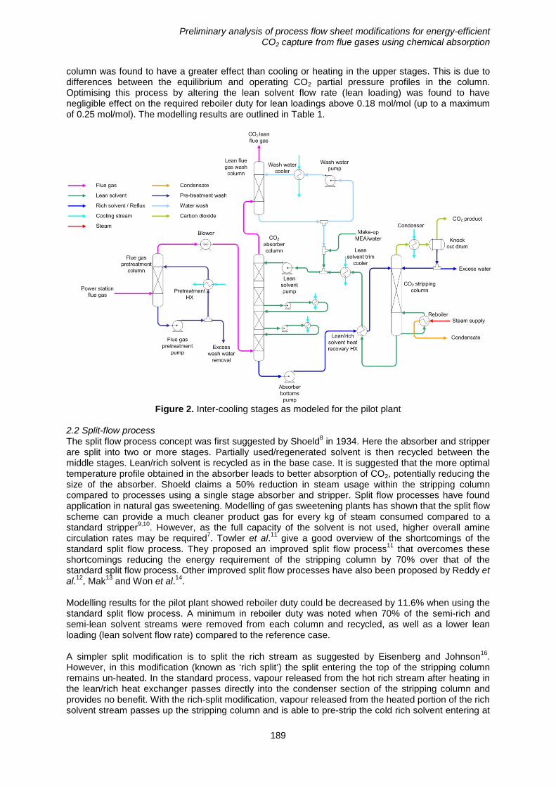
the top of the stripping column. Predicted CO2 vapour flow rates in the stripping column showed additional release of CO2 in the upper stages of the column when the rich split process is used. A minimum in reboiler duty was noted when 30% of the cold rich solvent stream was split to the top of the column. This was found to be due to the more optimal use of the lean/rich heat exchanger achieved with this split fraction. Modelling results are given in Table 1. 2.3 Vapour recompression In vapour recompression schemes, steam is extracted from one part of the stripping column, recompressed and either condensed with the heat of condensation providing part of the reboiler duty, or reintroduced into the column to provide additional stripping steam. A simplified version of the vapour recompression concept outlined by Benson and McRea17 was modelled for the pilot plant, as shown in Figure 3. Only the lean solvent flash and subsequent vapour compression was modelled. The flue gas cooling and additional vapour generation by heat exchange with the lean solvent and reflux as suggested in the patent have not been included at this stage. Lower solvent flow rates (lean loading) than the reference case were found to give a minimum in the required reboiler duty. This is likely due to the additional stripping steam shifting the equilibrium profile in the stripping column. The results from this modelling are listed in Table 1.
Figure 3. Vapour recompression with solvent regeneration as modeled for the pilot plant
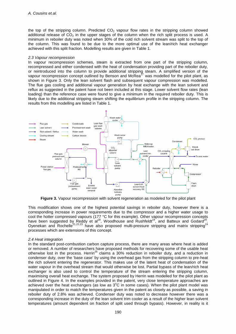
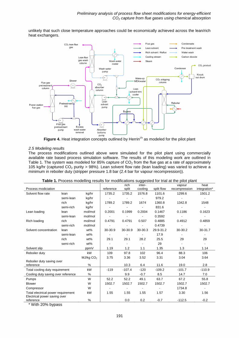
This modification shows one of the highest potential savings in reboiler duty, however there is a corresponding increase in power requirements due to the compressor and a higher water usage to cool the hotter compressed vapours (177 °C for this example). Other vapour recompression concepts have been suggested by Reddy et al18, Woodhouse and Rushfeldt19, and Batteux and Godard20. Oyenekan and Rochelle21,22,23 have also proposed multi-pressure stripping and matrix stripping24 processes which are extensions of this concept. 2.4 Heat integration In the standard post-combustion carbon capture process, there are many areas where heat is added or removed. A number of researchers have proposed methods for recovering some of the usable heat otherwise lost in the process. Herrin25 claims a 30% reduction in reboiler duty, and a reduction in condenser duty, over the ‘base case’ by using the overhead gas from the stripping column to pre-heat the rich solvent entering the regenerator. This makes use of the latent heat of condensation of the water vapour in the overhead stream that would otherwise be lost. Partial bypass of the lean/rich heat exchanger is also used to control the temperature of the stream entering the stripping column, maximising overall heat exchange. The system proposed by Herrin was modelled for the pilot plant as outlined in Figure 4. In the examples provided in the patent, very close temperature approaches are achieved over the heat exchangers (as low as 3oC in some cases). When the pilot plant model was manipulated in order to match the temperatures given in the patent as closely as possible, a saving in reboiler duty of 2.8% was achieved. Condenser duty was noted to decrease however there was a corresponding increase in the duty of the lean solvent trim cooler as a result of the higher lean solvent temperatures (amount dependent on fraction of split used through bypass). However, in reality is it
Preliminary analysis of process flow sheet modifications for energy-efficient CO2 capture from flue gases using chemical absorption
191
unlikely that such close temperature approaches could be economically achieved across the lean/rich heat exchangers.
Figure 4. Heat integration concepts outlined by Herrin25 as modeled for the pilot plant
2.5 Modeling results The process modifications outlined above were simulated for the pilot plant using commercially available rate based process simulation software. The results of this modeling work are outlined in Table 1. The system was modeled for 85% capture of CO2 from the flue gas at a rate of approximately 105 kg/hr (captured CO2 purity > 98%). Lean solvent flow rate (lean loading) was varied to achieve a minimum in reboiler duty (stripper pressure 1.8 bar (2.4 bar for vapour recompression)).
Table 1. Process modelling results for modifications suggested for trial at the pilot plant
Process modiciation reference rich split
inter-cooling split flow
vapour recompression
heat integration*
Solvent flow rate lean kg/hr 1735.2 1735.2 1576.8 1101.6 1299.6 1501.2 semi-lean kg/hr - - - 979.2 - - rich kg/hr 1789.2 1789.2 1674 1360.8 1342.8 1548 semi-rich kg/hr - - - 831.6 - - Lean loading lean mol/mol 0.2001 0.1999 0.2004 0.1467 0.1186 0.1623 semi-lean mol/mol - - - 0.3592 - - Rich loading rich mol/mol 0.4791 0.4791 0.507 0.4885 0.4912 0.4859 semi-rich mol/mol - - - 0.4739 - - Solvent concentration lean wt% 30-30.9 30-30.9 30-30.3 29.9-31.2 30-30.2 30-31.7 semi-lean wt% - - - 17.9 - - rich wt% 29.1 29.1 28.2 25.5 29 29 semi-rich wt% - - - 29 - - Solvent slip ppmV 1.19 1.2 1.1 1.35 1.3 1.14 Reboiler duty kW 109 97.8 102 96.4 88.3 106 MJ/kg CO2 3.75 3.36 3.52 3.31 3.04 3.64 Reboiler duty saving over reference % 10.3 6.4 11.6 19.0 2.8 Total cooling duty requirement kW -119 -107.4 -120 -109.2 -101.7 -110.9 Cooling duty saving over reference % 9.9 -0.7 8.5 14.7 7.0 Pumps W 52.2 52.2 49.1 63.7 67.2 55.8 Blower W 1502.7 1502.7 1502.7 1502.7 1502.7 1502.7 Compressor W - - - - 1734.8 - Total electrical power requirement kW 1.55 1.55 1.55 1.57 3.30 1.56 Electrical power saving over reference % 0.0 0.2 -0.7 -112.5 -0.2
* With 20% bypass
A. Cousins et.al.
192
3. Conclusions A review of PCC process modifications aimed at lowering the energy penalty highlighted several options, predominantly applicable in the gas processing industry. These options included the split flow process8, using cool rich solvent as reflux (rich split)16, vapour recompression resulting from lean solvent flashing17, inter-stage cooling6, and some heat integration concepts25,6. The process modifications were modelled using commercially available modelling software. Reboiler duty savings ranged between 2.8 – 19.0%. Vapour recompression was found to give the highest saving in terms of reboiler duty. However, there is a corresponding increase in total energy consumption resulting from the compression. In the end, the choice of process modification implemented will be determined by the overall economics of the system. For the pilot plant, concepts such as ‘Rich split’ are favorable due to its simplicity whilst still being able to achieve moderate energy savings. Further work will focus on optimising and validating the most relevant process flow sheet modifications in the pilot plant Acknowledgements This project was carried out within the Research stream on Post-Combustion Capture in CSIRO’s Coal Technology Portfolio. It received funding from the Australian Government as part of the Asia-Pacific Partnership on Clean Development and Climate. The views expressed herein are not necessarily the views of the Commonwealth, and the Commonwealth does not accept responsibility for any information or advice contained herein. References 1. D. Adams and J. Davison, IEA Greenhouse Gas R&D Programme Report, IEA (2007) 2. A Cousins, L.T. Wardhaugh, P.H.M Feron, submitted to Int. J. Greenhouse Gas Control, (2009) 3. A. Aroonwilas, P. Tontiwachwuthikul, A., Chakma, Sep. Purif. Technol. 24 (2001) 403-411 4. A. Aroonwilas, A. Veawab, Patent No. WO 2007/07004 A1, University of Regina (2007) 5. I.L. Leites, D.A. Sama, N. Lior, Energy, 28 (2003) 55-97 6. B. Woertz, Patent No. US 3266220 A1, Union Oil Co. (1966) 7. S.A. Geleff, Patent No. WO 2004073838 A1, Union Engineering (2004) 8. M. Shoeld, Patent No. US 1971798, The Koppers Co. (1934) 9. J.C., Polasek, J.A. Bullin, A.T. Donnelly, Proceedings of the 1982 AIChE Spring National Meeting,
New York (1982) 10. L. Lyddon, H. Nguyen, Proceedings of the Seventy-Eighth GPA Annual Convention, Nashville
(1999) 11. G.P. Towler, H.K. Shethna, B. Cole, B. Hajdik, Proceedings of the Seventy-Sixth GPA Annual
Convention, Tulsa, OK (1997) 12. S. Reddy, J. Scherffius, J. Gilmartin, S. Freguia, Patent No. WO 2004005818 A2, Fluor
Corporation (2004) 13. J. Mak, Patent No. CA 2605649 A1, Fluor Technologies Corporation (2007) 14. R. Won, P. Condorelli, J. Scherffius, C. Mariz, Patent No. US 6800120 B1, Fluor Corporation
(2004) 15. A. Aroonwilas, Seventh International Conference on Greenhouse Gas Control Technologies,
Vancouver, Canada (2004) 16. B. Eisenberg, R.R. Johnson, Patent No. US 4152217 A1, Exxon Research and Engineering
Company (1979) 17. H. Benson, D. McRea, Patent No. US 4160810 A1, Benfield Corporation (1979) 18. S. Reddy, J. Gilmartin, V. Francuz, Patent No. WO 2007075466 A2, Fluor Technologies
Corporation (2007) 19. S. Woodhouse, O. Rushfeldt, Patent No. WO 2008/063079 A2, Aker Clean Carbon (2008) 20. J. Batteux, A. Godard, Patent No. US 4384875 A1, Societe Nationale Elf Aquitaine (1983) 21. B.A. Oyenekan, G.T. Rochelle, Proceedings of the Eighth International Conference on
Greenhouse Gas Control Technologies, Trondheim, Norway (2006) 22. B.A. Oyenekan, G.T. Rochelle, Ind. Eng. Chem. Res., 45 (2006) 2457-2464 23. G. Rochelle, Patent No. WO 2004080573 A1, The board of Regents – The University of Texas
system (2004) 24. G.T. Rochelle, B.A. Oyenekan, Patent No. US 2008/0127831, (2008) 25. J.P Herrin, Patent No. US 4798910, (1989)