preliminary - digi-key sheets/projects unlimited pdfs... · preliminary pui audio, inc. ... (ip...
TRANSCRIPT
Preliminary
PUI Audio, Inc. A Projects Unlimited Company, 3541 Stop Eight Road, Dayton, OH 45414 Tel: (937) 415-5901 Fax: (937) 415-5925
Wake on Sound™ Piezoelectric MEMS Microphone
Evaluation Module
Data Sheet PMM-3738-VM1010-EB-R
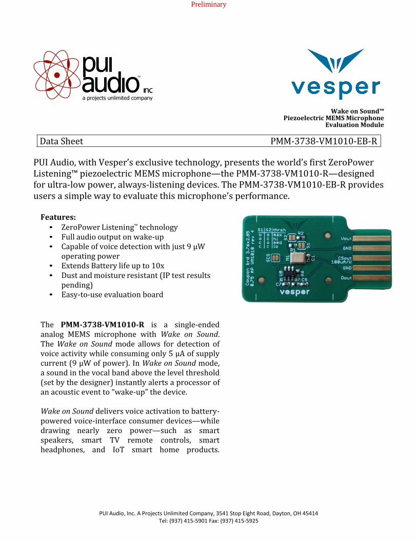
PUI Audio, with Vesper’s exclusive technology, presents the world’s first ZeroPower Listening™ piezoelectric MEMS microphone—the PMM-3738-VM1010-R—designed for ultra-low power, always-listening devices. The PMM-3738-VM1010-EB-R provides users a simple way to evaluate this microphone’s performance.
Features: • ZeroPower Listening™ technology • Full audio output on wake-up • Capable of voice detection with just 9 µW
operating power • Extends Battery life up to 10x • Dust and moisture resistant (IP test results
pending) • Easy-to-use evaluation board
The PMM-3738-VM1010-R is a single-ended analog MEMS microphone with Wake on Sound. The Wake on Sound mode allows for detection of voice activity while consuming only 5 µA of supply current (9 µW of power). In Wake on Sound mode, a sound in the vocal band above the level threshold (set by the designer) instantly alerts a processor of an acoustic event to “wake-up” the device. Wake on Sound delivers voice activation to battery-powered voice-interface consumer devices—while drawing nearly zero power—such as smart speakers, smart TV remote controls, smart headphones, and IoT smart home products.

Preliminary
PUI Audio, Inc. A Projects Unlimited Company, 3541 Stop Eight Road, Dayton, OH 45414 Tel: (937) 415-5901 Fax: (937) 415-5925
Specifications
All specifications are at 25°C, VSupply = 1.8 V unless otherwise noted.
Parameter Symbol Conditions Min. Typ. Max. Units
Normal Mode Acoustic Specifications
Sensitivity 1 kHz, 94 dB SPL -41 -38 -35 dBV
Signal-to-Noise Ratio
SNR 94 dB SPL at 1 kHz signal, 60 dB(A)
20 Hz – 20 kHz, A-weighted Noise
Signal-to Noise Ration Voice Band
SNR 94 dB SPL at 1 kHz signal, 62 dB(A)
20 Hz – 8 kHz, A-weighted
Total Harmonic Distortion
THD 94 dB SPL 0.1 %
Acoustic Overload Point
AOP 10.0% THD 122 dB SPL
Roll Off Frequency -3db at 1 kHz 100 Hz
Directivity Omni
Wake on Sound Acoustic Specifications
Acoustic Threshold
PaTH Peak Acoustic Stimulus Rg1 = Open
78 SPL
Acoustic Threshold
PaTH Peak Acoustic Stimulus, Rg1 = 300 kOhm
72 SPL

Preliminary
PUI Audio, Inc. A Projects Unlimited Company, 3541 Stop Eight Road, Dayton, OH 45414 Tel: (937) 415-5901 Fax: (937) 415-5925
Normal Mode Electrical Specifications
Supply Voltage VDD 1.6 1.8 3.6 V
Supply Current VDD ≤ 3.6 V, Mode Normal 85 110 μA Power Supply
Rejection Ratio PSRR VDD = 1.8, 1kHz, 200mVPP
Sine wave
-42 dB
Power Supply Rejection
PSR VDD = 1.8, 217Hz, 100mVPP
square wave, 20 Hz – 20kHz,
A-weighted
-74 dB(A)
Output Impedance ZOUT 700 Ω
Output DC Offset 0.8 V
Wake on Sound Mode Electrical Specifications
Supply Voltage VDD 1.6 1.8 3.6 V
Supply Current VDD ≤ 3.6 V, Mode WoS 5 μA
Digital Electrical Interface Specifications
Logic Input High 0.65*VDD 3.6 V
Logic Input Low -0.3 0.35*VDD V
Logic Output High ILoad = 2mA 0.7*VDD VDD V
Logic Output Low ILoad = 2mA 0 0.3*VDD V
Driving Capability 100 pF
Preliminary
PUI Audio, Inc. A Projects Unlimited Company, 3541 Stop Eight Road, Dayton, OH 45414 Tel: (937) 415-5901 Fax: (937) 415-5925
Absolute Maximum Ratings
Parameter Maximum Units
Supply Voltage 3.6 V
Sound Pressure Level 160 dB re 20 μPa
Temperature Range -40 to +85 °C
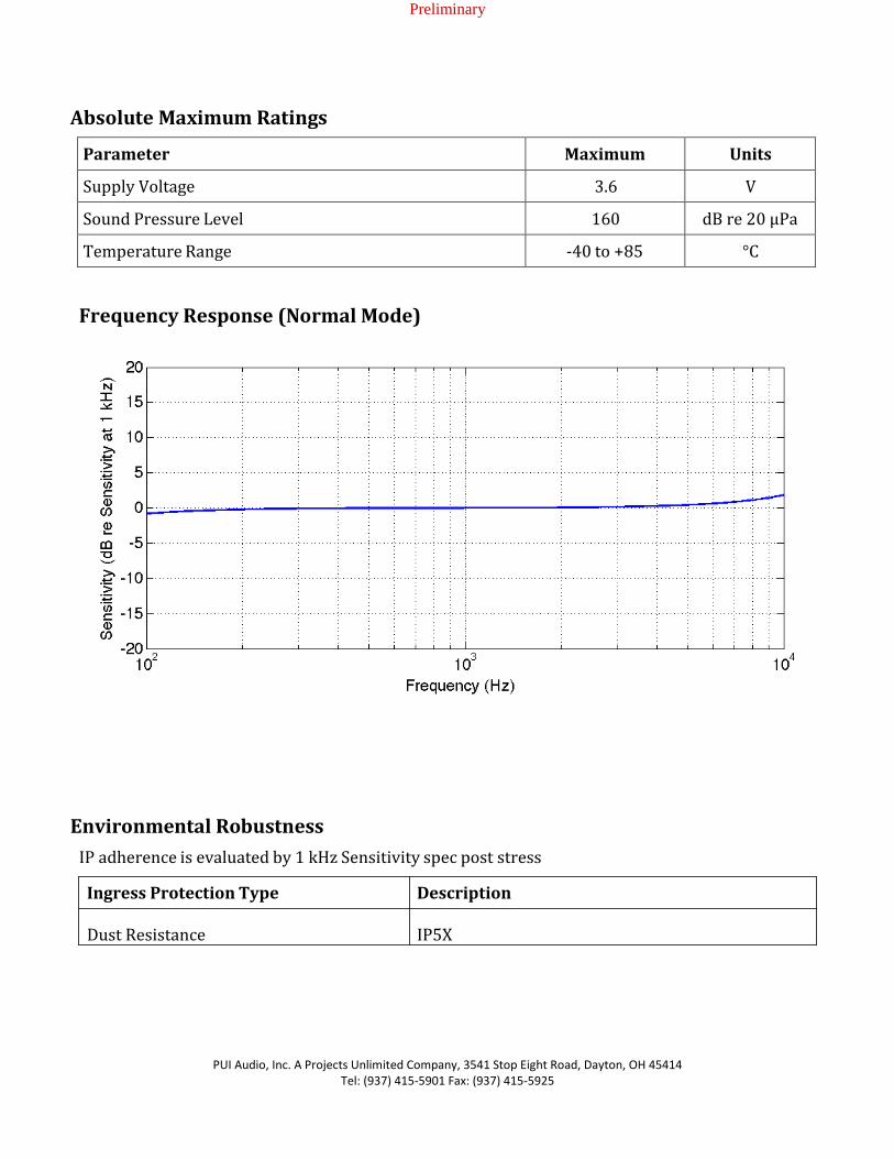
Frequency Response (Normal Mode)
Environmental Robustness
IP adherence is evaluated by 1 kHz Sensitivity spec post stress
Ingress Protection Type Description
Dust Resistance IP5X
Preliminary
PUI Audio, Inc. A Projects Unlimited Company, 3541 Stop Eight Road, Dayton, OH 45414 Tel: (937) 415-5901 Fax: (937) 415-5925
Microphone Modes
mode pin Mic mode Idd, typ. (µA) Vout pin dout pin high Wake-on-Sound 5 GND low, then latches high
after first wake-up event low or
floating Normal-Power 85 audio
output Tied to GND through low
impedance Microphone Operation
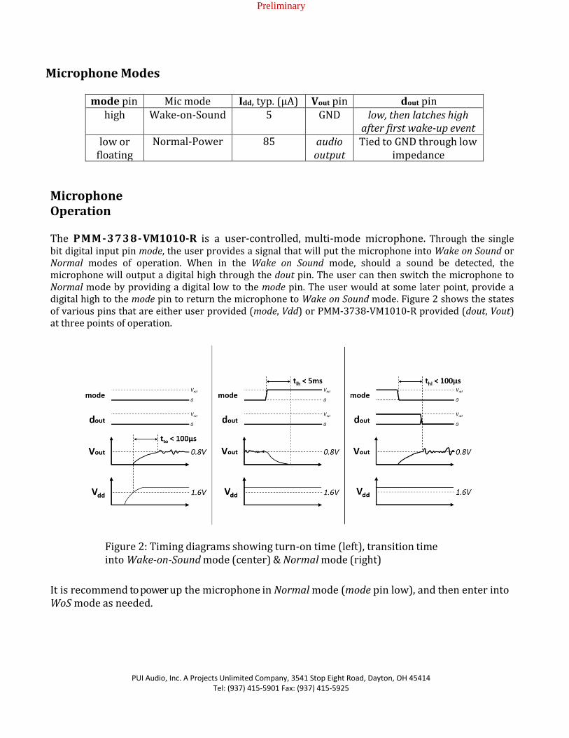
The PMM-3738-VM1010-R is a user-controlled, multi-mode microphone. Through the single bit digital input pin mode, the user provides a signal that will put the microphone into Wake on Sound or Normal modes of operation. When in the Wake on Sound mode, should a sound be detected, the microphone will output a digital high through the dout pin. The user can then switch the microphone to Normal mode by providing a digital low to the mode pin. The user would at some later point, provide a digital high to the mode pin to return the microphone to Wake on Sound mode. Figure 2 shows the states of various pins that are either user provided (mode, Vdd) or PMM-3738-VM1010-R provided (dout, Vout) at three points of operation.
Figure 2: Timing diagrams showing turn-on time (left), transition time into Wake-on-Sound mode (center) & Normal mode (right)
It is recommend to power up the microphone in Normal mode (mode pin low), and then enter into WoS mode as needed.

Preliminary
PUI Audio, Inc. A Projects Unlimited Company, 3541 Stop Eight Road, Dayton, OH 45414 Tel: (937) 415-5901 Fax: (937) 415-5925
System Architecture
A. Control loop for Wake-on-Sound:
Figure 3: Block diagram of example system built around the PMM-3738-VM1010- R microphone
In the figure above, the PMM-3738-VM1010-R microphone wakes up the system when triggered by sound. The DSP or Voice Processor can be kept in a low-power state when there is no sound to process.
Preliminary
PUI Audio, Inc. A Projects Unlimited Company, 3541 Stop Eight Road, Dayton, OH 45414 Tel: (937) 415-5901 Fax: (937) 415-5925
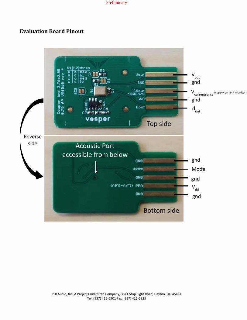
Evaluation Board Pinout
Acoustic Port
accessible from below
Vout
gnd
Vcurrentsense
(supply current monitor)
dout
gnd
gnd
Mode
gnd
gnd
Vdd
Top side
Bottom side
Reverse
side

Preliminary
PUI Audio, Inc. A Projects Unlimited Company, 3541 Stop Eight Road, Dayton, OH 45414 Tel: (937) 415-5901 Fax: (937) 415-5925
Wiring to Edge-Connector
The recommended edge-connector is CW Industries CWR-170-10-0000.
The Vdd supply range is 1.7V to 3.6V
dout
gnd Vcurrentsense
gnd Vout
gnd Mode gnd Vdd
gnd

Preliminary
PUI Audio, Inc. A Projects Unlimited Company, 3541 Stop Eight Road, Dayton, OH 45414 Tel: (937) 415-5901 Fax: (937) 415-5925
Wake on Sound threshold adjustment
• The evaluation board has a resistor circuit to configure the Wake-on-
Sound threshold to pre-set levels
• The solder jumper options S1 and S2 set the Wake-on-Sound threshold:
VM1010 Internal Circuitry
WoS Threshold Adjust Circuit
Board Solder Jumper Options
Preliminary
PUI Audio, Inc. A Projects Unlimited Company, 3541 Stop Eight Road, Dayton, OH 45414 Tel: (937) 415-5901 Fax: (937) 415-5925
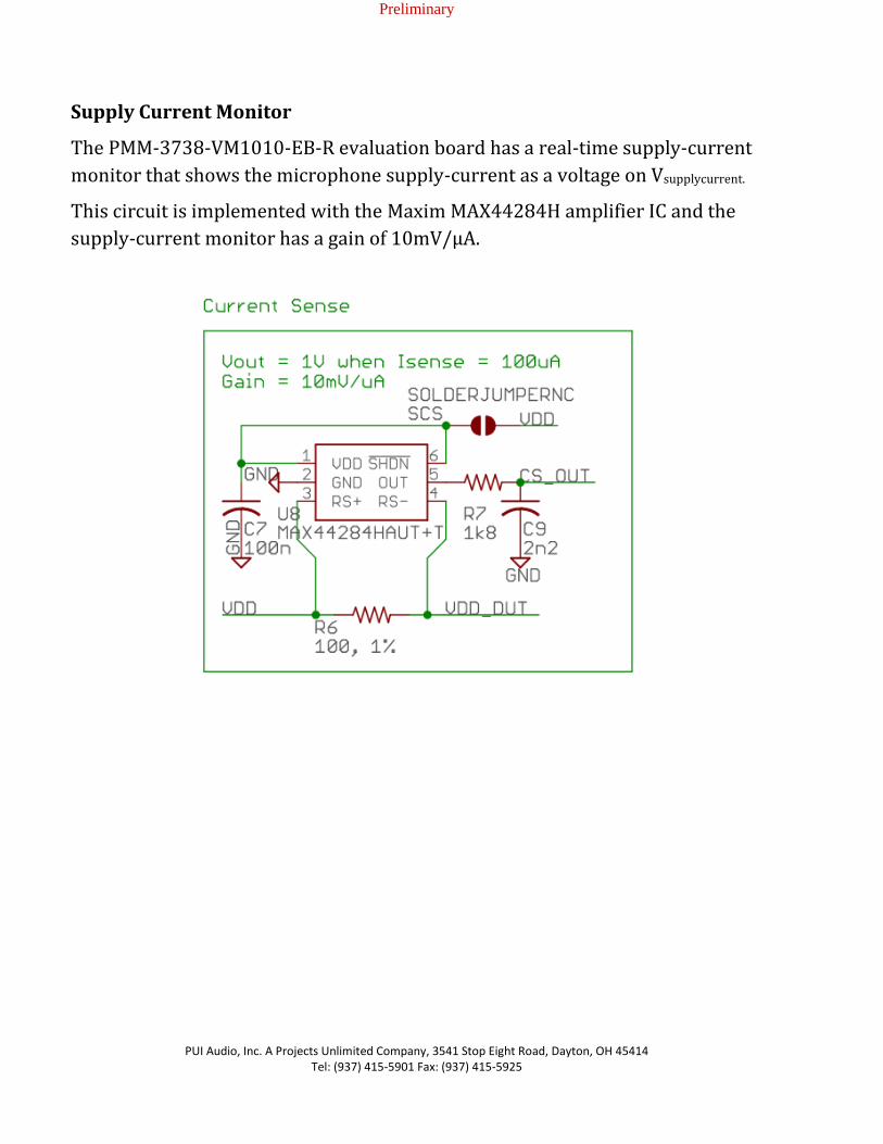
Supply Current Monitor
The PMM-3738-VM1010-EB-R evaluation board has a real-time supply-current
monitor that shows the microphone supply-current as a voltage on Vsupplycurrent.
This circuit is implemented with the Maxim MAX44284H amplifier IC and the
supply-current monitor has a gain of 10mV/µA.
Preliminary
PUI Audio, Inc. A Projects Unlimited Company, 3541 Stop Eight Road, Dayton, OH 45414 Tel: (937) 415-5901 Fax: (937) 415-5925
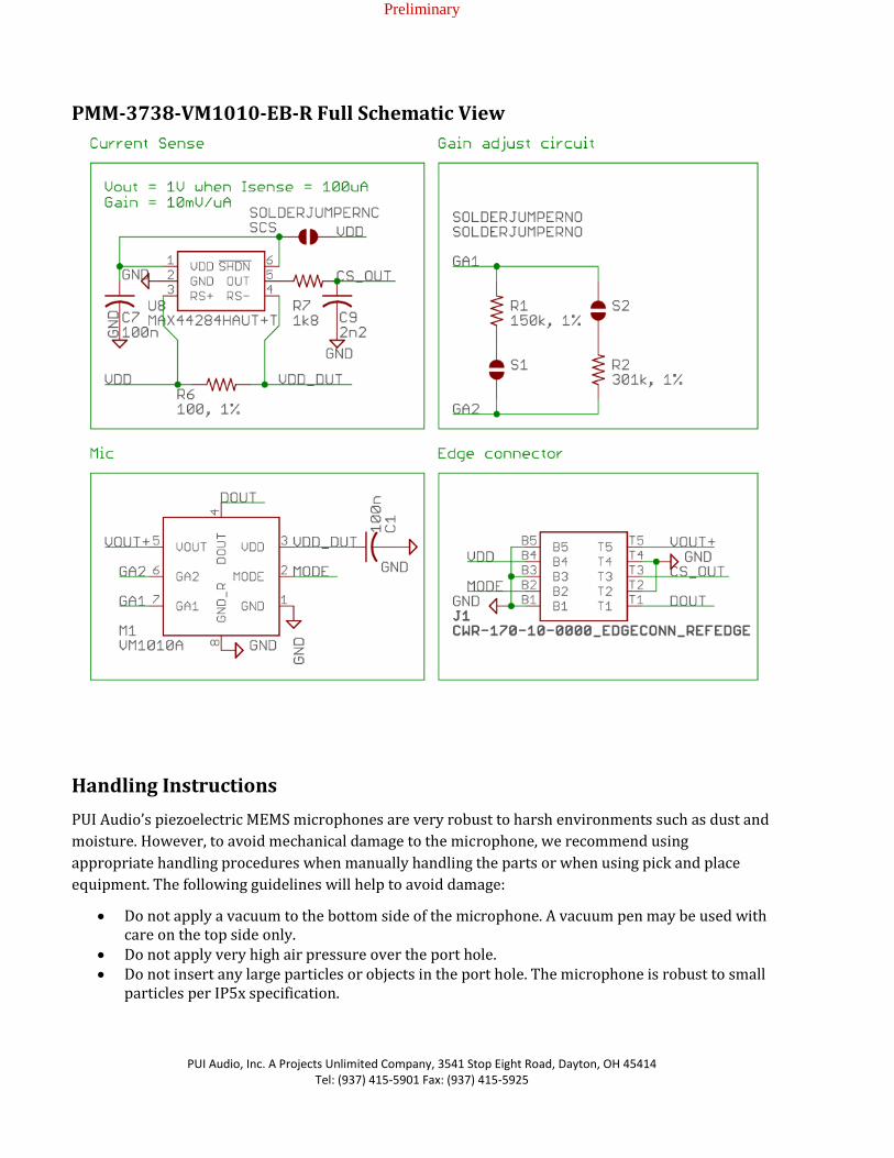
PMM-3738-VM1010-EB-R Full Schematic View
Handling Instructions
PUI Audio’s piezoelectric MEMS microphones are very robust to harsh environments such as dust and
moisture. However, to avoid mechanical damage to the microphone, we recommend using
appropriate handling procedures when manually handling the parts or when using pick and place
equipment. The following guidelines will help to avoid damage:
Do not apply a vacuum to the bottom side of the microphone. A vacuum pen may be used with care on the top side only.
Do not apply very high air pressure over the port hole. Do not insert any large particles or objects in the port hole. The microphone is robust to small
particles per IP5x specification.

Preliminary
PUI Audio, Inc. A Projects Unlimited Company, 3541 Stop Eight Road, Dayton, OH 45414 Tel: (937) 415-5901 Fax: (937) 415-5925
PMM-3738-VM1010-R Dimensions and Pin Layout
Pin Number Pin Name Description 1 GND Ground 2 mode Mode control (hi=Wake-on-Sound, lo=Normal-
Power) 3 Vdd Power Supply (1.6V to 3.6V) 4 dout Digital output for Wake-on-Sound trigger 5 Vout Analog Output Voltage 6 GA2 Wake-on-Sound Acoustic Threshold Adjust pin 2 7 GA1 Wake-on-Sound Acoustic Threshold Adjust pin 1 8 GND Ground
Engineering Samples
Engineering samples are date coded 1737 or lower. Engineering samples may vary from the technical
specifications contained in this data sheet, are not intended for use in end-products, and are intended
for evaluation and testing, only. The performance of an engineering sample may not reflect the
performance of a final product.
Preliminary
PUI Audio, Inc. A Projects Unlimited Company, 3541 Stop Eight Road, Dayton, OH 45414 Tel: (937) 415-5901 Fax: (937) 415-5925
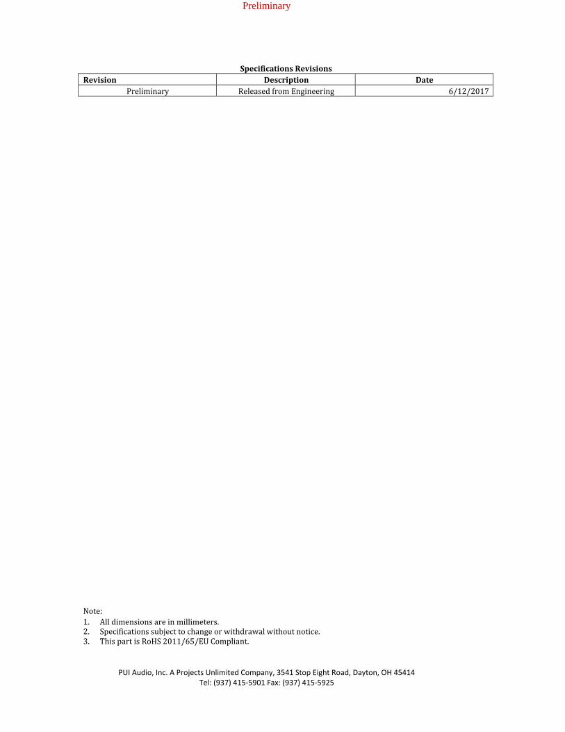
Specifications Revisions
Revision Description Date
Preliminary Released from Engineering 6/12/2017
Note:
1. All dimensions are in millimeters. 2. Specifications subject to change or withdrawal without notice. 3. This part is RoHS 2011/65/EU Compliant.