preliminary geotechnical data report - scdot.org€¦ · preliminary geotechnical data report ebp-3...
TRANSCRIPT

Preliminary Geotechnical Data Report Emergency Bridge Package 3 –
S-21-57 (North Old River Road) Bridge Replacement
over Barfield Mill Creek
Florence County, South Carolina
November 13, 2015
Terracon Project No. 73155050F
Prepared for:
South Carolina Department of Transportation
Columbia, South Carolina
Prepared by:
Terracon Consultants, Inc.
Columbia, South Carolina

Terracon Consultants, Inc. 521 Clemson Road Columbia, South Carolina 29229
P [803] 741 9000 F [803] 741 9900 terracon.com
November 13, 2015
South Carolina Department of Transportation
955 Park Street, Room 421
Columbia, South Carolina 29201
Attn: Mr. Trapp Harris, P.E.
Geotechnical Design Engineer – Design-Build Section
Re: Preliminary Geotechnical Data Report
Emergency Bridge Package 3 –
S-21-57 (North Old River Road) Bridge Replacement over Barfield Mill Creek
Florence County, South Carolina
Terracon Project Number: 73155050F
Dear Mr. Harris:
Terracon Consultants Inc. (Terracon) has completed the geotechnical exploration and
testing services for the above referenced project. These services were conducted in
general accordance with the SCDOT Request for Subsurface Exploration and Laboratory
Testing dated November 5, 2015. This geotechnical data report presents the findings of the
subsurface exploration and laboratory testing along with an overview of testing activities.
1.0 INTRODUCTION
The South Carolina Department of Transportation (SCDOT) has contracted Terracon to
perform the subsurface exploration and laboratory testing for the Emergency Bridge
Package 3 - S-21-57 (North Old River Road) Bridge Replacement over Barfield Mill Creek in
Florence County, South Carolina. The purpose of this work is to develop information
relative to subsurface soil and groundwater conditions at the bridge location. This report
presents the results of that work. No geotechnical recommendations are associated with the
requested scope of study.
The following sections of this report contain a summary of the activities our field exploration
and laboratory testing. The logs of the borings and CPT soundings, the Site Location Map
and the Exploration Plan are included in Appendix A of this report. The results of the
laboratory testing performed on soil samples obtained from the site during the field
exploration are included in Appendix B of this report. Descriptions of the field exploration
and laboratory testing are included in their respective appendices.
Preliminary Geotechnical Data Report EBP-3 - S-21-57 BRO Barfield Mill Creek■ Florence County, SC November 13, 2015 ■ Terracon Project No. 73155050F
Responsive ■ Resourceful ■ Reliable 2
2.0 PROJECT DESCRIPTION
The project site is located on S-21-57 (North Old River Road) in Florence County, SC. Site
location and boring locations plans are presented in Appendix A of this report. It is our
understanding that the project will include the demolition/removal of the existing bridge
structure and the replacement with a new bridge on the existing or similar horizontal
alignment. The existing bridge is a 3-span structure apparently supported by wooden piles.
It crosses Barfield Mill Creek. At the time of the field exploration, the surface of the stream
flow was about 13 feet below the existing bridge deck.
3.0 GEOTECHNICAL TESTING
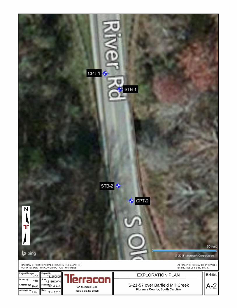
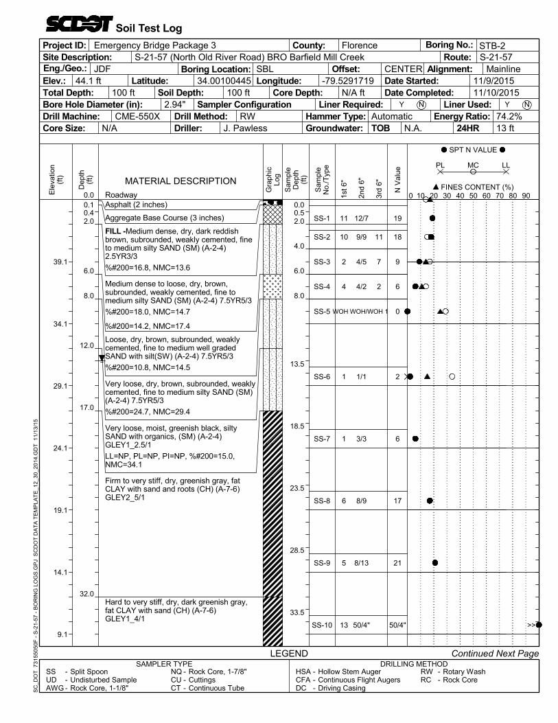
Between November 6 and November 9, 2015, two (2) soil test borings (designated STB-1
and STB-2) and two cone penetration test soundings (designated CPT-1 and CPT-2) were
performed at the bridge location. Borings STB-1 and STB-2 were performed approximately
10 feet to the north and south of the ends of the existing bridge, respectively, as shown on
Exhibit A-2 in Appendix A. The CPT soundings were performed slightly further away in the
adjacent lanes to the soil borings.
3.1 Field Exploration
Our field exploration at the site consisted of two (2) Standard Penetration Test (SPT)
Borings (STB-1 and STB-2) and two cone penetration test (CPT) soundings (CPT-1 and
CPT-2) at the general test locations provided to Terracon by the SCDOT. A description of
our testing methods and graphical logs outlining the soil conditions at each test location are
presented in Appendix A. The test locations were established in the field by Terracon and
surveyed by Construction Support Services, LLC, after completion. At the time of our field
exploration, the roadway in the area of the bridge was closed due to a washout of each of
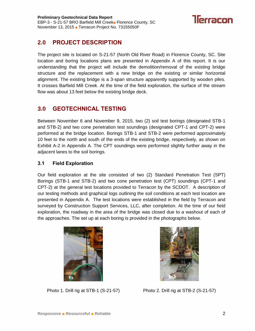
the approaches. The set up at each boring is provided in the photographs below.
Photo 1. Drill rig at STB-1 (S-21-57) Photo 2. Drill rig at STB-2 (S-21-57)

Preliminary Geotechnical Data Report EBP-3 - S-21-57 BRO Barfield Mill Creek■ Florence County, SC November 13, 2015 ■ Terracon Project No. 73155050F
Responsive ■ Resourceful ■ Reliable 3
3.2 Laboratory Testing
The following laboratory tests were performed on the soil samples collected at the site.
Twelve (12) Natural Moisture Content Tests (ASTM D2216)
Three (3) Atterberg Limits Tests (ASTM D4318)
Twelve (12) Wash #200 Tests
The laboratory procedures and results of the laboratory tests are presented in Appendix B.
4.0 CLOSURE
We appreciate the opportunity to be of service to you on this project. If you have any
questions concerning this report or we may be of further service, please contact us.
Sincerely,
Terracon Consultants, Inc.
Joseph D.M. Fredendall, E.I.T. Phillip A. Morrison, P.E.
Field Engineer Geotechnical Department Manager
SC Registration No. 17275
Attachments Copies: Addressee (1 via email)
File (1)
APPENDIX A - FIELD EXPLORATION
Exhibit A-1 – Site Location Map
Exhibit A-2 – Exploration Plan
Exhibit A-3 – Summary of Boring Data
Exhibit A-4 – Field Testing Description
Exhibit A-5 – Soil Description Terms
Exhibits A-6 and A-7 - Boring Logs
Exhibits A-8 to A-11 – CPT Sounding Logs

SITE LOCATION
S-21-57 over Barfield Mill Creek Florence County, South Carolina
TOPOGRAPHIC MAP IMAGE COURTESY OF THE U.S. GEOLOGICAL SURVEY QUADRANGLES INCLUDE: PAMPLICO NORTH, SC (1/1/1986) and PAMPLICO SOUTH, SC (1/1/1990).
521 Clemson Road
Columbia, SC 29229
73155050F Project Manager:
Drawn by: Checked by:
Approved by:
PTK
PAM
PAM
1”=24,000 SF A-1 & A-2
Nov. 2015
Project No.
Scale: File Name:
Date: A-1
Exhibit JDF
EXPLORATION PLAN
S-21-57 over Barfield Mill Creek Florence County, South Carolina
521 Clemson Road
Columbia, SC 29229
DIAGRAM IS FOR GENERAL LOCATION ONLY, AND IS NOT INTENDED FOR CONSTRUCTION PURPOSES
73155050F
AERIAL PHOTOGRAPHY PROVIDED BY MICROSOFT BING MAPS
PTK
PAM
PAM
AS SHOWN A-1 & A-2
Nov. 2015
Scale:
A-2
Exhibit Project Manager:
Drawn by: Checked by:
Approved by:
Project No.
File Name:
Date:
JDF
Preliminary Geotechnical Data Report EBP-3 - S-21-57 BRO Barfield Mill Creek■ Florence County, SC November 13, 2015 ■ Terracon Project No. 73155050F
Responsive ■ Resourceful ■ Reliable Exhibit A-3
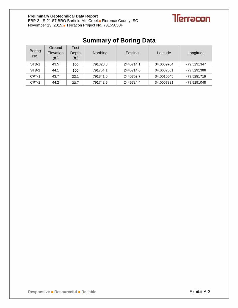
Summary of Boring Data
Boring
No.
Ground
Elevation
(ft.)
Test
Depth
(ft.)
Northing Easting Latitude Longitude
STB-1 43.5 100 791828.8 2445714.1 34.0009704 -79.5291347
STB-2 44.1 100 791754.1 2445714.0 34.0007651 -79.5291388
CPT-1 43.7 33.1 791841.0 2445702.7 34.0010045 -79.5291719
CPT-2 44.2 30.7 791742.5 2445724.4 34.0007331 -79.5291048

Preliminary Geotechnical Data Report EBP-3 - S-21-57 BRO Barfield Mill Creek■ Florence County, SC November 13, 2015 ■ Terracon Project No. 73155050F
Responsive ■ Resourceful ■ Reliable Exhibit A-4
FIELD EXPLORATION DESCRIPTION
Overview
The testing locations were provided by the SCDOT and located in the field by Terracon by
taking measurements from the existing bridge. The borings were surveyed by Construction
Support Services, LLC after drilling was complete. The locations are shown on the Exploration
Plan (Exhibit A-2).
A field log of each test location was prepared by our field engineer. The final boring logs included
with this report represent the engineer's description of the encountered conditions modified as
necessary based on laboratory test results of the individual samples.
Soil Test Borings (STB)
All boring and sampling operations were conducted in general accordance with the following
procedures:
SCDOT Geotechnical Design Manual 2010
ASTM D5783, “Standard Guide for Use of Direct Rotary Drilling with Water-Based Drilling
Fluid for Geo-environmental Exploration”
ASTM D1586 “Test Method for Penetration Test and Split-Barrel Sampling of Soils”
ASTM D4220 “Standard Practices for Preserving and Transporting Soil”
Each boring was advanced using rotary wash drilling techniques. Five samples were collected
in the upper 10 feet. Below that depth, samples were obtained at 5-foot intervals. Soil samples
were obtained with a standard 1.4-inch I.D., 2-inch O.D., split-barrel sampler, also known as a
standard split-spoon. The sampler is advanced into the soil a total of 18 inches (24-inches in
the upper 10 feet) by striking the drill rod using a 140-pound automatic hammer falling 30
inches. The number of blows required to advance the sampler for each of the three, 6-inch
increments is recorded. A fourth reading was recorded in the upper 10 feet. The sum of the
number of blows for the second and third increments is called the “Standard Penetration Value”,
or N-value (Nmeas, blows per foot). The N-value, when properly evaluated, is an index to the soil
strength.
Soil Classification provides a general guide to the engineering properties of various soil types
and enables the engineer to apply his experience to current situations. In our exploration,
samples obtained during drilling operations are examined and visually classified by a
geotechnical engineer using the procedures outlined in ASTM D2487 - Standard Classification
of Soils for Engineering Purposes (Unified Soil Classification System). Laboratory testing was
also performed on select split-spoon samples to evaluate index properties for further
classification. The soils are described according to color, texture, and relative density or
consistency (based on standard penetration resistance). An explanation of the soil descriptions
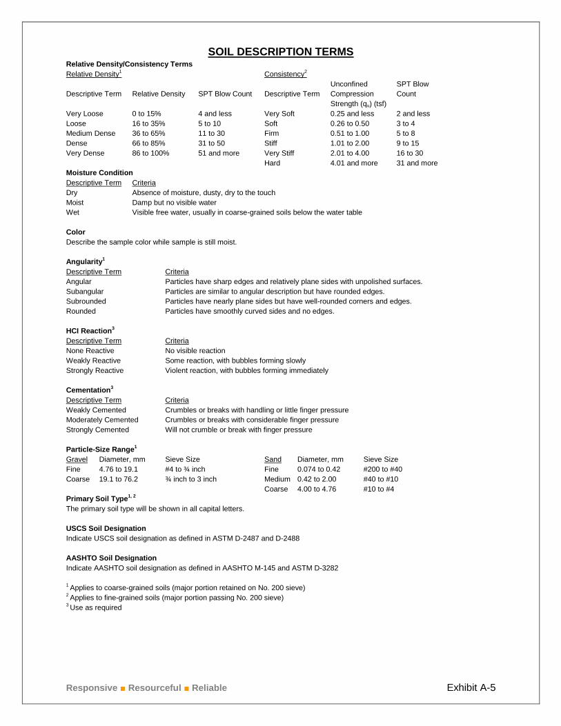
shown on the logs is provided on Exhibit A-5.
Preliminary Geotechnical Data Report EBP-3 - S-21-57 BRO Barfield Mill Creek■ Florence County, SC November 13, 2015 ■ Terracon Project No. 73155050F
Responsive ■ Resourceful ■ Reliable Exhibit A-4
Due to the drilling method, time-of-drilling water levels could not be recorded as it as well as the
rock coring introduces water into the borehole. The 24-hour groundwater readings were
collected from the borings, where possible. These are indicated on the boring logs. At the
conclusion of the work, the boreholes were backfilled and capped with cold-patch asphalt.
Cone Penetration Test Soundings (CPT)
Cone Penetration Test soundings were conducted in general accordance with ASTM
D5778 Standard Test Method for Performing Electronic Friction Cone and Piezocone
Penetration Testing of Soils.
Responsive ■ Resourceful ■ Reliable Exhibit A-5
SOIL DESCRIPTION TERMS Relative Density/Consistency Terms
Relative Density1 Consistency
2
Unconfined SPT Blow
Descriptive Term Relative Density SPT Blow Count Descriptive Term Compression Count
Strength (qu) (tsf)
Very Loose 0 to 15% 4 and less Very Soft 0.25 and less 2 and less
Loose 16 to 35% 5 to 10 Soft 0.26 to 0.50 3 to 4
Medium Dense 36 to 65% 11 to 30 Firm 0.51 to 1.00 5 to 8
Dense 66 to 85% 31 to 50 Stiff 1.01 to 2.00 9 to 15
Very Dense 86 to 100% 51 and more Very Stiff 2.01 to 4.00 16 to 30
Hard 4.01 and more 31 and more
Moisture Condition
Descriptive Term Criteria
Dry Absence of moisture, dusty, dry to the touch
Moist Damp but no visible water
Wet Visible free water, usually in coarse-grained soils below the water table
Color
Describe the sample color while sample is still moist.
Angularity1
Descriptive Term Criteria
Angular Particles have sharp edges and relatively plane sides with unpolished surfaces.
Subangular Particles are similar to angular description but have rounded edges.
Subrounded Particles have nearly plane sides but have well-rounded corners and edges.
Rounded Particles have smoothly curved sides and no edges.
HCI Reaction3
Descriptive Term Criteria
None Reactive No visible reaction
Weakly Reactive Some reaction, with bubbles forming slowly
Strongly Reactive Violent reaction, with bubbles forming immediately
Cementation3
Descriptive Term Criteria
Weakly Cemented Crumbles or breaks with handling or little finger pressure
Moderately Cemented Crumbles or breaks with considerable finger pressure
Strongly Cemented Will not crumble or break with finger pressure
Particle-Size Range1
Gravel Diameter, mm Sieve Size Sand Diameter, mm Sieve Size
Fine 4.76 to 19.1 #4 to ¾ inch Fine 0.074 to 0.42 #200 to #40
Coarse 19.1 to 76.2 ¾ inch to 3 inch Medium 0.42 to 2.00 #40 to #10
Coarse 4.00 to 4.76 #10 to #4
Primary Soil Type1, 2
The primary soil type will be shown in all capital letters.
USCS Soil Designation
Indicate USCS soil designation as defined in ASTM D-2487 and D-2488
AASHTO Soil Designation
Indicate AASHTO soil designation as defined in AASHTO M-145 and ASTM D-3282
1 Applies to coarse-grained soils (major portion retained on No. 200 sieve)
2 Applies to fine-grained soils (major portion passing No. 200 sieve)
3 Use as required

5
10
5
4
WOH
3
3
6
7
7
10
15
14
4
/1 2
8/9
10/10
9/11
3/3
WOH
2/1
5/4
7/9
8/11
11/13
0.10.4
4.0
6.0
8.0
12.0
17.0
22.0
32.0
Asphalt (2 inches)
Aggregate Base Course (3 inches)
FILL -Medium dense, dry, yellowish red,angular, weakly cemented, fine to mediumsilty SAND (SM) (A-2-4) 5YR5/6
%#200=16.2, NMC=12.4
FILL -Medium dense, dry, yellowish red,angular, weakly cemented, fine to mediumwell graded SAND with silt and asphaltfragments (SW) (A-2-4) 5YR5/6
%#200=11.8, NMC=15.1
FILL -Loose, dry, yellowish red to gray,angular, weakly cemented, fine to mediumsilty SAND with asphalt fragments (SM)(A-2-4) 5YR5/6 to 7.5YR4/1
%#200=25.2, NMC=19.1
FILL -Very loose, dry, yellowish red ,angular, weakly cemented, fine to mediumwell graded SAND with silt and asphaltfragments (SW) (A-2-4) 5YR5/6
%#200=10.1, NMC=19.9
Very loose, dry, gray, well graded SANDwith silt (A-3) 7.5YR3/1
LL=NP, PL=NP, PI=NP, %#200=9.7,NMC=28.3
Loose, moist, greenish gray, subrounded,weakly cemented, fine to medium clayeySAND (SC) (A-2-4) GLEY2_5/1
Very stiff, moist, greenish gray, fat CLAYwith sand (CH) (A-7-6) GLEY2_5/1
LL=63, PL=22, PI=41, %#200=83.9,NMC=33.4
Very stiff, moist, very dark greenish gray,fat CLAY with sand (CH) (A-7-6)GLEY2_3/1
0.0
2.0
4.0
6.0
8.0
13.5
18.5
23.5
28.5
33.5
17
20
20
6
1
3
9
16
19
24
SS-1
SS-2
SS-3
SS-4
SS-5
SS-6
SS-7
SS-8
SS-9
SS-10
Offset: Alignment:
TOB
Y
RWCME-550X
34.00097044
N.A.
S-21-57 (North Old River Road) BRO Barfield Mill Creek
11/9/201511/10/2015
Site Description:
Sampler Configuration Liner Required:
1st
6"
2nd
6"
3rd
6"
0.0 Roadway
Project ID:
Eng./Geo.:Latitude:
Core Size:
Longitude: Date Started:Total Depth: Date Completed:Bore Hole Diameter (in):Drill Machine:
Continued Next Page
RWRC
--
HSACFADC
JDF
---
Elev.:
Rotary WashRock Core
Rock Core, 1-7/8"CuttingsContinuous Tube
SAMPLER TYPE
-79.52913474
Driller:Energy Ratio:
NBL
2.94"
CENTER
Drill Method:
Mainline
N/A
Soil Depth: Core Depth:
LEGEND
Boring Location:
N/A ft
Hollow Stem AugerContinuous Flight AugersDriving Casing
Hammer Type:
Route:
Groundwater: 24HR
Liner Used:
12 ft
100 ft43.5 ft
Ele
vatio
n(f
t)
38.5
33.5
28.5
23.5
18.5
13.5
8.5
Dep
th(f
t) MATERIAL DESCRIPTION
Sam
ple
Dep
th(f
t)
N V
alue
Gra
phic
Log
100 ftY
Sam
ple
No.
/Typ
e
SPT N VALUE
FINES CONTENT (%)10 20 30 40 50 60 70 80 900
FlorenceCounty:
PL LL
DRILLING METHOD---
74.2%
NQCUCT
---
Boring No.:
Split SpoonUndisturbed SampleRock Core, 1-1/8"
Emergency Bridge Package 3S-21-57
Automatic
MC
STB-1
Soil Test Log
SSUDAWG
J. Pawless
SC
_DO
T 7
3155
050
F -
S-2
1-57
- B
OR
ING
LO
GS
.GP
J S
CD
OT
DA
TA
TE
MP
LAT
E_1
2_30
_20
14.G
DT
11
/13/
15
NN

13
5
3
40
12
4
9
12/11
50/2"
5/50/2"
21/22
11/12
7/10
11/17
42.0
62.0
67.0
Hard to very stiff, moist, very dark greenishgray, fat CLAY with sand and rockfragments (CH) (A-7-6) GLEY2_3/1
Very stiff, moist, greenish gray, fat CLAYwith sand (CH) (A-7-6) GLEY2_5/1
Medium dense, moist, greenish gray,rounded, moderately cemented, fine tomedium clayey SAND (SC) (A-6)GLEY2_5/1
38.5
43.5
48.5
53.5
58.5
63.5
68.5
23
50/2"
50/2"
43
23
17
28
SS-11
SS-12
SS-13
SS-14
SS-15
SS-16
SS-17
Offset: Alignment:
TOB
Y
RWCME-550X
34.00097044
N.A.
S-21-57 (North Old River Road) BRO Barfield Mill Creek
11/9/201511/10/2015
Site Description:
Sampler Configuration Liner Required:
1st
6"
2nd
6"
3rd
6"
Project ID:
Eng./Geo.:Latitude:
Core Size:
Longitude: Date Started:Total Depth: Date Completed:Bore Hole Diameter (in):Drill Machine:
Continued Next Page
RWRC
--
HSACFADC
JDF
---
Elev.:
Rotary WashRock Core
Rock Core, 1-7/8"CuttingsContinuous Tube
SAMPLER TYPE
-79.52913474
Driller:Energy Ratio:
NBL
2.94"
CENTER
Drill Method:
Mainline
N/A
Soil Depth: Core Depth:
LEGEND
Boring Location:
N/A ft
Hollow Stem AugerContinuous Flight AugersDriving Casing
Hammer Type:
Route:
Groundwater: 24HR
Liner Used:
12 ft
100 ft43.5 ft
Ele
vatio
n(f
t)
3.5
-1.5
-6.5
-11.5
-16.5
-21.5
-26.5
Dep
th(f
t) MATERIAL DESCRIPTION
Sam
ple
Dep
th(f
t)
N V
alue
Gra
phic
Log
100 ftY
Sam
ple
No.
/Typ
e
SPT N VALUE
FINES CONTENT (%)10 20 30 40 50 60 70 80 900
FlorenceCounty:
PL LL
DRILLING METHOD---
74.2%
NQCUCT
---
Boring No.:
Split SpoonUndisturbed SampleRock Core, 1-1/8"
Emergency Bridge Package 3S-21-57
Automatic
MC
STB-1
Soil Test Log
SSUDAWG
J. Pawless
SC
_DO
T 7
3155
050
F -
S-2
1-57
- B
OR
ING
LO
GS
.GP
J S
CD
OT
DA
TA
TE
MP
LAT
E_1
2_30
_20
14.G
DT
11
/13/
15
>>
>>
NN

11
9
9
50/2"
50/1"
50/5"
9/18
11/50/4"
12/47
77.0
82.0
87.0
92.0
97.0
100.0
Very dense, moist, greenish gray, rounded,moderately cemented, fine to mediumclayey SAND (SC) (A-6) GLEY2_5/1
Hard, moist, greenish gray, fat CLAY withsand (CH) (A-7-6) GLEY2_5/1
Very dense, moist, greenish gray, rounded,weakly cemented, fine silty SAND (SM)(A-2-4) GLEY2_6/1
Very dense, moist, greenish gray, rounded,weakly cemented, fine silty clayey SAND(SM-SC) (A-2-4) GLEY2_6/1
No Recovery
Boring Terminated at 100 feet
73.5
78.5
83.5
88.5
93.5
98.5
27
50/4"
59
50/2"
50/1"
50/5"
SS-18
SS-19
SS-20
SS-21
SS-22
SS-23
Offset: Alignment:
TOB
Y
RWCME-550X
34.00097044
N.A.
S-21-57 (North Old River Road) BRO Barfield Mill Creek
11/9/201511/10/2015
Site Description:
Sampler Configuration Liner Required:
1st
6"
2nd
6"
3rd
6"
Project ID:
Eng./Geo.:Latitude:
Core Size:
Longitude: Date Started:Total Depth: Date Completed:Bore Hole Diameter (in):Drill Machine:
RWRC
--
HSACFADC
JDF
---
Elev.:
Rotary WashRock Core
Rock Core, 1-7/8"CuttingsContinuous Tube
SAMPLER TYPE
-79.52913474
Driller:Energy Ratio:
NBL
2.94"
CENTER
Drill Method:
Mainline
N/A
Soil Depth: Core Depth:
LEGEND
Boring Location:
N/A ft
Hollow Stem AugerContinuous Flight AugersDriving Casing
Hammer Type:
Route:
Groundwater: 24HR
Liner Used:
12 ft
100 ft43.5 ft
Ele
vatio
n(f
t)
-31.5
-36.5
-41.5
-46.5
-51.5
-56.5
-61.5
Dep
th(f
t) MATERIAL DESCRIPTION
Sam
ple
Dep
th(f
t)
N V
alue
Gra
phic
Log
100 ftY
Sam
ple
No.
/Typ
e
SPT N VALUE
FINES CONTENT (%)10 20 30 40 50 60 70 80 900
FlorenceCounty:
PL LL
DRILLING METHOD---
74.2%
NQCUCT
---
Boring No.:
Split SpoonUndisturbed SampleRock Core, 1-1/8"
Emergency Bridge Package 3S-21-57
Automatic
MC
STB-1
Soil Test Log
SSUDAWG
J. Pawless
SC
_DO
T 7
3155
050
F -
S-2
1-57
- B
OR
ING
LO
GS
.GP
J S
CD
OT
DA
TA
TE
MP
LAT
E_1
2_30
_20
14.G
DT
11
/13/
15
>>
>>
>>
>>
NN
11
10
2
4
1
1
6
5
13
11
7
2
12/7
9/9
4/5
4/2
1/1
3/3
8/9
8/13
50/4"
0.10.42.0
6.0
8.0
12.0
17.0
32.0
Asphalt (2 inches)
Aggregate Base Course (3 inches)
FILL -Medium dense, dry, dark reddishbrown, subrounded, weakly cemented, fineto medium silty SAND (SM) (A-2-4)2.5YR3/3
%#200=16.8, NMC=13.6
Medium dense to loose, dry, brown,subrounded, weakly cemented, fine tomedium silty SAND (SM) (A-2-4) 7.5YR5/3
%#200=18.0, NMC=14.7
%#200=14.2, NMC=17.4
Loose, dry, brown, subrounded, weaklycemented, fine to medium well gradedSAND with silt(SW) (A-2-4) 7.5YR5/3
%#200=10.8, NMC=14.5
Very loose, dry, brown, subrounded, weaklycemented, fine to medium silty SAND (SM)(A-2-4) 7.5YR5/3
%#200=24.7, NMC=29.4
Very loose, moist, greenish black, siltySAND with organics, (SM) (A-2-4)GLEY1_2.5/1
LL=NP, PL=NP, PI=NP, %#200=15.0,NMC=34.1
Firm to very stiff, dry, greenish gray, fatCLAY with sand and roots (CH) (A-7-6)GLEY2_5/1
Hard to very stiff, dry, dark greenish gray,fat CLAY with sand (CH) (A-7-6)GLEY1_4/1
0.00.52.0
4.0
6.0
8.0
13.5
18.5
23.5
28.5
33.5
19
18
9
6
0
2
6
17
21
50/4"
SS-1
SS-2
SS-3
SS-4
SS-5
SS-6
SS-7
SS-8
SS-9
SS-10
Offset: Alignment:
TOB
Y
RWCME-550X
34.00100445
N.A.
S-21-57 (North Old River Road) BRO Barfield Mill Creek
11/9/201511/10/2015
Site Description:
Sampler Configuration Liner Required:
1st
6"
2nd
6"
3rd
6"
0.0 Roadway
Project ID:
Eng./Geo.:Latitude:
Core Size:
Longitude: Date Started:Total Depth: Date Completed:Bore Hole Diameter (in):Drill Machine:
Continued Next Page
RWRC
--
HSACFADC
JDF
---
Elev.:
Rotary WashRock Core
Rock Core, 1-7/8"CuttingsContinuous Tube
SAMPLER TYPE
-79.5291719
Driller:Energy Ratio:
SBL
2.94"
CENTER
Drill Method:
Mainline
N/A
Soil Depth: Core Depth:
LEGEND
Boring Location:
N/A ft
Hollow Stem AugerContinuous Flight AugersDriving Casing
Hammer Type:
Route:
Groundwater: 24HR
Liner Used:
13 ft
100 ft44.1 ft
Ele
vatio
n(f
t)
39.1
34.1
29.1
24.1
19.1
14.1
9.1
Dep
th(f
t) MATERIAL DESCRIPTION
Sam
ple
Dep
th(f
t)
N V
alue
Gra
phic
Log
100 ftY
Sam
ple
No.
/Typ
e
SPT N VALUE
FINES CONTENT (%)10 20 30 40 50 60 70 80 900
FlorenceCounty:
PL LL
DRILLING METHOD---
74.2%
NQCUCT
---
Boring No.:
Split SpoonUndisturbed SampleRock Core, 1-1/8"
Emergency Bridge Package 3S-21-57
Automatic
MC
STB-2
Soil Test Log
SSUDAWG
J. Pawless
SC
_DO
T 7
3155
050
F -
S-2
1-57
- B
OR
ING
LO
GS
.GP
J S
CD
OT
DA
TA
TE
MP
LAT
E_1
2_30
_20
14.G
DT
11
/13/
15
>>
NN
WOH WOH/WOH 1

7
50/1"
48
10
8
5
6
12/14
38/32
12/24
8/10
8/8
12/18
42.0
57.0
Hard, dry, dark greenish gray, fat CLAYwith sand (CH) (A-7-6) GLEY1_4/1
Very stiff to hard, dry, dark greenish gray,fat CLAY with sand (CH) (A-7-6)GLEY1_4/1
38.5
43.5
48.5
53.5
58.5
63.5
68.5
26
50/1"
70
36
18
16
30
SS-11
SS-12
SS-13
SS-14
SS-15
SS-16
SS-17
Offset: Alignment:
TOB
Y
RWCME-550X
34.00100445
N.A.
S-21-57 (North Old River Road) BRO Barfield Mill Creek
11/9/201511/10/2015
Site Description:
Sampler Configuration Liner Required:
1st
6"
2nd
6"
3rd
6"
Project ID:
Eng./Geo.:Latitude:
Core Size:
Longitude: Date Started:Total Depth: Date Completed:Bore Hole Diameter (in):Drill Machine:
Continued Next Page
RWRC
--
HSACFADC
JDF
---
Elev.:
Rotary WashRock Core
Rock Core, 1-7/8"CuttingsContinuous Tube
SAMPLER TYPE
-79.5291719
Driller:Energy Ratio:
SBL
2.94"
CENTER
Drill Method:
Mainline
N/A
Soil Depth: Core Depth:
LEGEND
Boring Location:
N/A ft
Hollow Stem AugerContinuous Flight AugersDriving Casing
Hammer Type:
Route:
Groundwater: 24HR
Liner Used:
13 ft
100 ft44.1 ft
Ele
vatio
n(f
t)
4.1
-0.9
-5.9
-10.9
-15.9
-20.9
-25.9
Dep
th(f
t) MATERIAL DESCRIPTION
Sam
ple
Dep
th(f
t)
N V
alue
Gra
phic
Log
100 ftY
Sam
ple
No.
/Typ
e
SPT N VALUE
FINES CONTENT (%)10 20 30 40 50 60 70 80 900
FlorenceCounty:
PL LL
DRILLING METHOD---
74.2%
NQCUCT
---
Boring No.:
Split SpoonUndisturbed SampleRock Core, 1-1/8"
Emergency Bridge Package 3S-21-57
Automatic
MC
STB-2
Soil Test Log
SSUDAWG
J. Pawless
SC
_DO
T 7
3155
050
F -
S-2
1-57
- B
OR
ING
LO
GS
.GP
J S
CD
OT
DA
TA
TE
MP
LAT
E_1
2_30
_20
14.G
DT
11
/13/
15
>>
NN

8
10
25
14
50/2"
50/2"
14/16
15/25
24/22
87.0
92.0
100.0
Very dense, wet, dark greenish gray,rounded, weakly cemented, fine silty SAND(SM) (A-2-4) GLEY1_4/1
No Recovery
Boring Terminated at 100 feet
73.5
78.5
83.5
88.5
93.5
98.5
30
40
46
50/3"
50/2"
50/2"
SS-18
SS-19
SS-20
SS-21
SS-22
SS-23
Offset: Alignment:
TOB
Y
RWCME-550X
34.00100445
N.A.
S-21-57 (North Old River Road) BRO Barfield Mill Creek
11/9/201511/10/2015
Site Description:
Sampler Configuration Liner Required:
1st
6"
2nd
6"
3rd
6"
Project ID:
Eng./Geo.:Latitude:
Core Size:
Longitude: Date Started:Total Depth: Date Completed:Bore Hole Diameter (in):Drill Machine:
RWRC
--
HSACFADC
JDF
---
Elev.:
Rotary WashRock Core
Rock Core, 1-7/8"CuttingsContinuous Tube
SAMPLER TYPE
-79.5291719
Driller:Energy Ratio:
SBL
2.94"
CENTER
Drill Method:
Mainline
N/A
Soil Depth: Core Depth:
LEGEND
Boring Location:
N/A ft
Hollow Stem AugerContinuous Flight AugersDriving Casing
Hammer Type:
Route:
Groundwater: 24HR
Liner Used:
13 ft
100 ft44.1 ft
Ele
vatio
n(f
t)
-30.9
-35.9
-40.9
-45.9
-50.9
-55.9
-60.9
Dep
th(f
t) MATERIAL DESCRIPTION
Sam
ple
Dep
th(f
t)
N V
alue
Gra
phic
Log
100 ftY
Sam
ple
No.
/Typ
e
SPT N VALUE
FINES CONTENT (%)10 20 30 40 50 60 70 80 900
FlorenceCounty:
PL LL
DRILLING METHOD---
74.2%
NQCUCT
---
Boring No.:
Split SpoonUndisturbed SampleRock Core, 1-1/8"
Emergency Bridge Package 3S-21-57
Automatic
MC
STB-2
Soil Test Log
SSUDAWG
J. Pawless
SC
_DO
T 7
3155
050
F -
S-2
1-57
- B
OR
ING
LO
GS
.GP
J S
CD
OT
DA
TA
TE
MP
LAT
E_1
2_30
_20
14.G
DT
11
/13/
15
>>
>>
>>
NN
25/50/3"

CPT Started: 11/7/2015
Rig: Pagani TG73-200
Probe no. 4526 with net area ratio of 0.83U2 pore pressure transducer locationManufactured by Geotech A.B.; calibrated 11/12/2014Tip and sleeve areas of 10 cm2 and 150 cm2
Ring friction reducer with O.D. of 1.875 in
12 ft estimated water depth(used in normalizations and correlations;
see Appendix C)
WATER LEVEL OBSERVATION
See Exhibit A-3 for description of field procedures.
See Appendix C for explanation of symbols and abbreviations.
SITE: S-21-57Florence County, South Carolina
4 Silt mixtures - clayey silt to silty clay5 Sand mixtures - silty sand to sandy silt6 Sands - clean sand to silty sand
1 Sensitive, fine grained2 Organic soils - clay3 Clay - silty clay to clay
CPT LOG NO. CPT-1CLIENT: SCDOT
Columbia, SC
Project No.: 73155050F521 Clemson Road
Columbia, South Carolina
PROJECT: See Exhibit A-2
Depth(ft)
0
5
10
15
20
25
30
35
40
45
S-21-57 (North Old River Road) RBOBarfield Mill Creek
7 Gravelly sand to dense sand8 Very stiff sand to clayey sand9 Very stiff fine grained
Latitude:Longitude:
34.001°-79.52917°
CPT Completed: 11/7/2015
Operator: BR
Station: SBLOffset: CENTER
TEST LOCATION:
Page 1 of 1
CPT sensor calibration reports available upon request.
TH
IS B
OR
ING
LO
G IS
NO
T V
ALI
D IF
SE
PA
RA
TE
D F
RO
M O
RIG
INA
L R
EP
OR
T.
C
PT
RE
PO
RT
73
1550
50F
- S
-21-
57 -
CP
T L
OG
S.G
PJ
TE
RR
AC
ON
2015
.GD
T 1
1/1
3/1
5
Elev.(ft)
40
35
30
25
20
15
10
5
0
-5
Tip Resistance, qt
(tsf)
90 180 270 360
MaterialDescription
Normalized CPTSoil Behavior Type1 2 3 4 5 6 7 8
Hydrostatic Pressure
Pore Pressure, u2
(tsf)
4 10 16 22
Sleeve Friction, fs
(tsf)
1 2 3 4
Friction Ratio, Fr
(%)
2 4 6
CPT Refused at 33.1 Feet
>>>>
>>>>
>>>>
Exhibit: A-8
Surface Elev.: 43.7 ft

CPT Completed: 11/7/2015Notes:Probe no. 4526 with net area ratio of 0.83Manufactured by Geotech A.B.; calibrated 11/12/2014Tip and sleeve areas of 10 cm2 and 150 cm2
Ring friction reducer with O.D. of 1.875 in
Depth(ft)
0
5
10
15
20
25
30
35
40
45
Latitude:Longitude:
34.00100445°-79.5291719°
WATER LEVEL OBSERVATION
SEE CPT LOG NO. CPT-1 FOR DETAILED TEST RESULTS
12 ft estimated water depth
CPT CORRELATIVE PARAMETER LOG NO. CPT-1 Page 1 of 1
Operator: BR
CLIENT: SCDOTColumbia, SC
PROJECT: TEST LOCATION:S-21-57 (North Old River Road) RBOBarfield Mill Creek
Station: SBLOffset: CENTER
(used in normalizations and correlations;see Appendix C)
SITE: S-21-57Florence County, South Carolina
Tip resistance, sleeve resistance, porewater pressure, and tilt angle are measured. Other parameters presented are derived from interpretations of the measured data, based upon published correlations, but do not necessarily representactual values that would be derived from direct testing. Appendix C provides the formulas used for these correlations and presents estimates of the relative reliability associated with the correlated parameters.
Project No.: 73155050F521 Clemson Road
Columbia, South Carolina
CPT Started: 11/7/2015
Rig: Pagani TG73-200
See Exhibit A-2
Exhibit: A-9
TH
IS B
OR
ING
LO
G IS
NO
T V
ALI
D IF
SE
PA
RA
TE
D F
RO
M O
RIG
INA
L R
EP
OR
T.
C
PT
CO
RR
ELA
TIV
E P
AR
AM
ET
ER
S R
EP
OR
T
7315
505
0F -
S-2
1-57
- C
PT
LO
GS
.GP
J T
ER
RA
CO
N20
15.G
DT
11/
13/1
5
Elev.(ft)
40
35
30
25
20
15
10
5
0
-5
MaterialDescription
Normalized CPTSoil Behavior Type
1 2 3 4 5 6 7 8(4)(3)
Elastic Modulus, Es
(tsf)
400 800 1200 160020 30 40 50(2)(1)
Effective Friction Angle(degrees)
20 30 40 50(1) (2)OCR
2 4 6 8
N60 Value
15 30 45 60
N60 Value
1.5 3.0 4.5 6.0Undrained
Shear Strength, Su
Nkt = 14(tsf)
0.4 0.8 1.2 1.6
CPT Refused at 33.1 Feet
Surface Elev.: 43.7 ft

CPT Started: 11/7/2015
Rig: Pagani TG73-200
Probe no. 4526 with net area ratio of 0.83U2 pore pressure transducer locationManufactured by Geotech A.B.; calibrated 11/12/2014Tip and sleeve areas of 10 cm2 and 150 cm2
Ring friction reducer with O.D. of 1.875 in
13 ft estimated water depth(used in normalizations and correlations;
see Appendix C)
WATER LEVEL OBSERVATION
See Exhibit A-3 for description of field procedures.
See Appendix C for explanation of symbols and abbreviations.
SITE: S-21-57Florence County, South Carolina
4 Silt mixtures - clayey silt to silty clay5 Sand mixtures - silty sand to sandy silt6 Sands - clean sand to silty sand
1 Sensitive, fine grained2 Organic soils - clay3 Clay - silty clay to clay
CPT LOG NO. CPT-2CLIENT: SCDOT
Columbia, SC
Project No.: 73155050F521 Clemson Road
Columbia, South Carolina
PROJECT: See Exhibit A-2
Depth(ft)
0
5
10
15
20
25
30
35
40
45
S-21-57 (North Old River Road) RBOBarfield Mill Creek
7 Gravelly sand to dense sand8 Very stiff sand to clayey sand9 Very stiff fine grained
Latitude:Longitude:
34.00073°-79.5291°
CPT Completed: 11/7/2015
Operator: BR
Station: NBLOffset: CENTER
TEST LOCATION:
Page 1 of 1
CPT sensor calibration reports available upon request.
Exhibit: A-10
TH
IS B
OR
ING
LO
G IS
NO
T V
ALI
D IF
SE
PA
RA
TE
D F
RO
M O
RIG
INA
L R
EP
OR
T.
C
PT
RE
PO
RT
73
1550
50F
- S
-21-
57 -
CP
T L
OG
S.G
PJ
TE
RR
AC
ON
2015
.GD
T 1
1/1
3/1
5
Elev.(ft)
40
35
30
25
20
15
10
5
0
-5
Tip Resistance, qt
(tsf)
90 180 270 360
MaterialDescription
Normalized CPTSoil Behavior Type1 2 3 4 5 6 7 8
Hydrostatic Pressure
Pore Pressure, u2
(tsf)
4 10 16 22
Sleeve Friction, fs
(tsf)
1 2 3 4
Friction Ratio, Fr
(%)
2 4 6
CPT Refused at 30.7 Feet
>>>>>>
Surface Elev.: 44.2 ft

CPT Completed: 11/7/2015Notes:Probe no. 4526 with net area ratio of 0.83Manufactured by Geotech A.B.; calibrated 11/12/2014Tip and sleeve areas of 10 cm2 and 150 cm2
Ring friction reducer with O.D. of 1.875 in
Depth(ft)
0
5
10
15
20
25
30
35
40
45
Latitude:Longitude:
34.00073308°-79.5291048°
WATER LEVEL OBSERVATION
SEE CPT LOG NO. CPT-2 FOR DETAILED TEST RESULTS
13 ft estimated water depth
CPT CORRELATIVE PARAMETER LOG NO. CPT-2 Page 1 of 1
Operator: BR
CLIENT: SCDOTColumbia, SC
PROJECT: TEST LOCATION:S-21-57 (North Old River Road) RBOBarfield Mill Creek
Station: NBLOffset: CENTER
(used in normalizations and correlations;see Appendix C)
SITE: S-21-57Florence County, South Carolina
Tip resistance, sleeve resistance, porewater pressure, and tilt angle are measured. Other parameters presented are derived from interpretations of the measured data, based upon published correlations, but do not necessarily representactual values that would be derived from direct testing. Appendix C provides the formulas used for these correlations and presents estimates of the relative reliability associated with the correlated parameters.
Project No.: 73155050F521 Clemson Road
Columbia, South Carolina
CPT Started: 11/7/2015
Rig: Pagani TG73-200
See Exhibit A-2
Exhibit: A-10
TH
IS B
OR
ING
LO
G IS
NO
T V
ALI
D IF
SE
PA
RA
TE
D F
RO
M O
RIG
INA
L R
EP
OR
T.
C
PT
CO
RR
ELA
TIV
E P
AR
AM
ET
ER
S R
EP
OR
T
7315
505
0F -
S-2
1-57
- C
PT
LO
GS
.GP
J T
ER
RA
CO
N20
15.G
DT
11/
13/1
5
Elev.(ft)
40
35
30
25
20
15
10
5
0
-5
MaterialDescription
Normalized CPTSoil Behavior Type
1 2 3 4 5 6 7 8(4)(3)
Elastic Modulus, Es
(tsf)
400 800 1200 160020 30 40 50(2)(1)
Effective Friction Angle(degrees)
20 30 40 50(1) (2)OCR
2 4 6 8
N60 Value
15 30 45 60
N60 Value
1.5 3.0 4.5 6.0Undrained
Shear Strength, Su
Nkt = 14(tsf)
0.4 0.8 1.2 1.6
CPT Refused at 30.7 Feet
Surface Elev.: 44.2 ft

APPENDIX B - LABORATORY TESTING
Exhibit B-1 – Laboratory Testing Description
Exhibit B-2 – Summary of Laboratory Data
Laboratory Data Sheets

Preliminary Geotechnical Data Report EBP-3 - S-21-57 BRO Barfield Mill Creek■ Florence County, SC November 13, 2015 ■ Terracon Project No. 73155050F
Responsive ■ Resourceful ■ Reliable Exhibit B-1
LABORATORY TESTING DESCRIPTION
The samples collected during the field exploration were taken to our laboratory for additional
testing. The laboratory testing program was developed by the SCDOT. Using the provided
testing program, the laboratory tests were conducted on selected soil samples from the borings
and the bulk samples locations. The test results are presented in this appendix
The laboratory test results were used to confirm the soil descriptions presented on the boring
logs in Appendix A. Laboratory tests were performed in general accordance with the applicable
ASTM, AASHTO, SCDOT or other accepted standards.
Selected soil samples obtained from the site were tested for the following engineering
properties:
Percent Fines AASHTO T11 (ASTM D1140) Atterberg Limits AASHTO T89/T90(ASTM D4318)
Moisture Content Determination AASHTO T265/(ASTM D2216)

STB-1 2 - 4 SILTY SAND (SM) 16.2 0.0 0.0 12.4
STB-1 4 - 6 SAND with silt (SW) 11.8 0.0 0.0 15.1
STB-1 6 - 8 SILTY SAND (SM) 25.2 0.0 0.0 19.1
STB-1 8 - 10 SAND with silt (SW) 10.1 0.0 0.0 19.9
STB-1 13.5 - 15 SAND with silt (SW) NP NP NP 9.7 0.0 0.0 28.3
STB-1 23.5 - 25 FAT CLAY with SAND(CH) 63 22 41 83.9 0.0 0.0 33.4
STB-2 0 - 2 SILTY SAND (SM) 16.8 0.0 0.0 13.6
STB-2 2 - 4 SILTY SAND (SM) 18.0 0.0 0.0 14.7
STB-2 4 - 6 SILTY SAND (SM) 14.2 0.0 0.0 17.4
STB-2 6 - 8 SAND with silt (SW) 10.8 0.0 0.0 14.5
STB-2 8 - 10 SILTY SAND (SM) 24.7 0.0 0.0 29.4
STB-2 13.5 - 15 SILTY SAND(SM) NP NP NP 15.0 0.0 0.0 34.1
Sheet 1 of 1
Summary of Laboratory Results
Depth USCS Classificationand Soil Description
CompressiveStrength
(tsf)
%<#200Sieve
DryDensity
(pcf)
WaterContent
(%)
BORINGID
LiquidLimit
PlasticLimit
PlasticityIndex
%Gravel
%Sand
%Silt
%Clay
521 Clemson RoadColumbia, South Carolina
PROJECT NUMBER: 73155050FPROJECT: S-21-57 BRO Barfield Mill Creek
SITE: S-21-57 Florence, South Carolina
CLIENT: SCDOT Columbia, South Carolina
EXHIBIT: B-2
LAB
OR
AT
OR
Y T
ES
TS
AR
E N
OT
VA
LID
IF S
EP
AR
AT
ED
FR
OM
OR
IGIN
AL
RE
PO
RT
.
OLD
-LA
B S
UM
MA
RY
: US
CS
731
5505
0F
- S
-21-
57 -
LA
B T
ES
TIN
G.G
PJ
TE
RR
AC
ON
2012
.GD
T 1
1/13
/15

0
10
20
30
40
50
60
0 20 40 60 80 100
CH o
r
OH
CL o
r
OL
ML or OL
MH or OH
PL PIBoring ID Depth Description
SAND with silt (SW)
FAT CLAY with SAND
SILTY SAND
CH
SM
Fines
PLASTICITY
INDEX
LIQUID LIMIT
"U" L
ine
"A" L
ine
NP
63
NP
NP
22
NP
NP
41
NP
10
84
15
LL USCS
STB-1
STB-1
STB-2
ATTERBERG LIMITS RESULTSASTM D4318
13.5 - 15
23.5 - 25
13.5 - 15
521 Clemson RoadColumbia, South Carolina
PROJECT NUMBER: 73155050FPROJECT: S-21-57 BRO Barfield Mill Creek
SITE: S-21-57 Florence, South Carolina
CLIENT: SCDOT Columbia, South Carolina
EXHIBIT: B-3
LAB
OR
AT
OR
Y T
ES
TS
AR
E N
OT
VA
LID
IF S
EP
AR
AT
ED
FR
OM
OR
IGIN
AL
RE
PO
RT
.
AT
TE
RB
ER
G L
IMIT
S 7
3155
050F
- S
-21
-57
- L
AB
TE
ST
ING
.GP
J T
ER
RA
CO
N20
15.G
DT
11/
13/1
5
CL-ML
APPENDIX C - SUPPORTING DOCUMENTS
Exhibit C-1 – General Notes
Exhibit C-2 – Unified Soil Classification System
TraceWithModifier
Water Level Aftera Specified Period of Time
GRAIN SIZE TERMINOLOGYRELATIVE PROPORTIONS OF SAND AND GRAVEL
TraceWithModifier
Standard Penetration orN-Value
Blows/Ft.
Descriptive Term(Consistency)
Loose
Very Stiff
Exhibit C-1
Standard Penetration orN-Value
Blows/Ft.
Ring SamplerBlows/Ft.
Ring SamplerBlows/Ft.
Medium Dense
Dense
Very Dense
0 - 1 < 3
4 - 9 2 - 4 3 - 4
Medium-Stiff 5 - 9
30 - 50
WA
TE
R L
EV
EL
Auger
Shelby Tube
Ring Sampler
Grab Sample
8 - 15
Split Spoon
Macro Core
Rock Core
PLASTICITY DESCRIPTION
Term
< 1515 - 29> 30
Descriptive Term(s)of other constituents
Water InitiallyEncountered
Water Level After aSpecified Period of Time
Major Componentof Sample
Percent ofDry Weight
(More than 50% retained on No. 200 sieve.)Density determined by Standard Penetration Resistance
Includes gravels, sands and silts.
Hard
Very Loose 0 - 3 0 - 6 Very Soft
7 - 18 Soft
10 - 29 19 - 58
59 - 98 Stiff
less than 500
500 to 1,000
1,000 to 2,000
2,000 to 4,000
4,000 to 8,000> 99
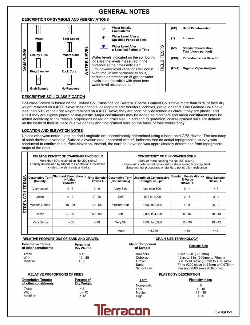
LOCATION AND ELEVATION NOTES
SA
MP
LIN
G
FIE
LD
TE
ST
S
(HP)
(T)
(b/f)
(PID)
(OVA)
DESCRIPTION OF SYMBOLS AND ABBREVIATIONS
Descriptive Term(Density)
Non-plasticLowMediumHigh
BouldersCobblesGravelSandSilt or Clay
10 - 18
> 50 15 - 30 19 - 42
> 30 > 42
_
Hand Penetrometer
Torvane
Standard PenetrationTest (blows per foot)
Photo-Ionization Detector
Organic Vapor Analyzer
Water levels indicated on the soil boringlogs are the levels measured in theborehole at the times indicated.Groundwater level variations will occurover time. In low permeability soils,accurate determination of groundwaterlevels is not possible with short termwater level observations.
CONSISTENCY OF FINE-GRAINED SOILS
(50% or more passing the No. 200 sieve.)Consistency determined by laboratory shear strength testing, field
visual-manual procedures or standard penetration resistance
DESCRIPTIVE SOIL CLASSIFICATION
> 8,000
Unless otherwise noted, Latitude and Longitude are approximately determined using a hand-held GPS device. The accuracyof such devices is variable. Surface elevation data annotated with +/- indicates that no actual topographical survey wasconducted to confirm the surface elevation. Instead, the surface elevation was approximately determined from topographicmaps of the area.
Soil classification is based on the Unified Soil Classification System. Coarse Grained Soils have more than 50% of their dryweight retained on a #200 sieve; their principal descriptors are: boulders, cobbles, gravel or sand. Fine Grained Soils haveless than 50% of their dry weight retained on a #200 sieve; they are principally described as clays if they are plastic, andsilts if they are slightly plastic or non-plastic. Major constituents may be added as modifiers and minor constituents may beadded according to the relative proportions based on grain size. In addition to gradation, coarse-grained soils are definedon the basis of their in-place relative density and fine-grained soils on the basis of their consistency.
Plasticity Index
01 - 1011 - 30
> 30
RELATIVE PROPORTIONS OF FINES
Descriptive Term(s)of other constituents
Percent ofDry Weight
< 55 - 12> 12
No Recovery
RELATIVE DENSITY OF COARSE-GRAINED SOILS
Particle Size
Over 12 in. (300 mm)12 in. to 3 in. (300mm to 75mm)3 in. to #4 sieve (75mm to 4.75 mm)#4 to #200 sieve (4.75mm to 0.075mmPassing #200 sieve (0.075mm)
ST
RE
NG
TH
TE
RM
S Unconfined CompressiveStrength, Qu, psf
4 - 8
GENERAL NOTES

Exhibit C-2
UNIFIED SOIL CLASSIFICATION SYSTEM
Criteria for Assigning Group Symbols and Group Names Using Laboratory Tests A Soil Classification
Group Symbol
Group Name B
Coarse Grained Soils: More than 50% retained on No. 200 sieve
Gravels: More than 50% of coarse fraction retained on No. 4 sieve
Clean Gravels: Less than 5% fines C
Cu 4 and 1 Cc 3 E GW Well-graded gravel F
Cu 4 and/or 1 Cc 3 E GP Poorly graded gravel F
Gravels with Fines: More than 12% fines C
Fines classify as ML or MH GM Silty gravel F,G,H
Fines classify as CL or CH GC Clayey gravel F,G,H
Sands: 50% or more of coarse fraction passes No. 4 sieve
Clean Sands: Less than 5% fines D
Cu 6 and 1 Cc 3 E SW Well-graded sand I
Cu 6 and/or 1 Cc 3 E SP Poorly graded sand I
Sands with Fines: More than 12% fines D
Fines classify as ML or MH SM Silty sand G,H,I
Fines classify as CL or CH SC Clayey sand G,H,I
Fine-Grained Soils: 50% or more passes the No. 200 sieve
Silts and Clays: Liquid limit less than 50
Inorganic: PI 7 and plots on or above “A” line J CL Lean clay K,L,M
PI 4 or plots below “A” line J ML Silt K,L,M
Organic: Liquid limit - oven dried
0.75 OL Organic clay K,L,M,N
Liquid limit - not dried Organic silt K,L,M,O
Silts and Clays: Liquid limit 50 or more
Inorganic: PI plots on or above “A” line CH Fat clay K,L,M
PI plots below “A” line MH Elastic Silt K,L,M
Organic: Liquid limit - oven dried
0.75 OH Organic clay K,L,M,P
Liquid limit - not dried Organic silt K,L,M,Q
Highly organic soils: Primarily organic matter, dark in color, and organic odor PT Peat
A Based on the material passing the 3-inch (75-mm) sieve B If field sample contained cobbles or boulders, or both, add “with cobbles
or boulders, or both” to group name. C Gravels with 5 to 12% fines require dual symbols: GW-GM well-graded
gravel with silt, GW-GC well-graded gravel with clay, GP-GM poorly graded gravel with silt, GP-GC poorly graded gravel with clay.
D Sands with 5 to 12% fines require dual symbols: SW-SM well-graded sand with silt, SW-SC well-graded sand with clay, SP-SM poorly graded sand with silt, SP-SC poorly graded sand with clay
E Cu = D60/D10 Cc =
6010
2
30
DxD
)(D
F If soil contains 15% sand, add “with sand” to group name. G If fines classify as CL-ML, use dual symbol GC-GM, or SC-SM.
H If fines are organic, add “with organic fines” to group name. I If soil contains 15% gravel, add “with gravel” to group name. J If Atterberg limits plot in shaded area, soil is a CL-ML, silty clay. K If soil contains 15 to 29% plus No. 200, add “with sand” or “with gravel,”
whichever is predominant. L If soil contains 30% plus No. 200 predominantly sand, add “sandy” to
group name. M If soil contains 30% plus No. 200, predominantly gravel, add
“gravelly” to group name. N PI 4 and plots on or above “A” line. O PI 4 or plots below “A” line. P PI plots on or above “A” line. Q PI plots below “A” line.