preliminary geotechnical hdd feasibility assessment · 2010-08-23 · preliminary geotechnical hdd...
TRANSCRIPT

AMEC Earth & Environmental a Division of AMEC Americas Limited2227 Douglas Road, Burnaby, BCCanada V5C 5A9Tel +1 (604) 294-3811Fax +1 (604) 294-4664www.amec.com
Preliminary Geotechnical HDD Feasibility Assessment
Athabasca River (Crossing #1975)
Proposed Enbridge Northern Gateway Project
Rev R KP187.4
Submitted to:
Northern Gateway Pipelines Inc.
Calgary, Alberta
Submitted by:
AMEC Earth & Environmental,a division of AMEC Americas Limited
Burnaby, BC
July 14, 2010
AMEC File: EG0926008.3000Document Control No. 1155-WC-20100714


Northern Gateway Pipelines Inc.Preliminary Geotechnical HDD Feasibility Assessment Athabasca River (Crossing #1975)July 14, 2010
AMEC File: EG0926008.3000 Page i
TABLE OF CONTENTS
Page
1.0 PROJECT DESCRIPTION ............................................................................................. 1-1
2.0 SCOPE........................................................................................................................... 2-1
3.0 GEOTECHNICAL AND HYDROTECHNICAL SITE CONDITIONS ................................. 3-1 3.1 Sources of Information........................................................................................... 3-1 3.2 Topography and Access ........................................................................................ 3-1 3.3 Geology ................................................................................................................. 3-2 3.4 Slope Stability ........................................................................................................ 3-4 3.5 Stream Characteristics........................................................................................... 3-5
3.5.1 Channel Description ................................................................................... 3-5 3.5.2 River Characteristics at Proposed Crossing ............................................... 3-5 3.5.3 Lateral Channel Stability............................................................................. 3-8 3.5.4 Depth of Scour ........................................................................................... 3-8
4.0 PRELIMINARY ASSESSMENT OF CROSSING METHODS.......................................... 4-1 4.1 Horizontal Directional Drill (HDD) Crossing ............................................................ 4-1 4.2 Contingency Crossing Method ............................................................................... 4-2
5.0 FUTURE GEOTECHNICAL WORK TO SUPPORT DETAILED DESIGN ....................... 5-1
6.0 CLOSURE...................................................................................................................... 6-1
REFERENCES........................................................................................................................ 6-2
LIST OF FIGURES
Figure 1: Mean Monthly Flows of Athabasca River at Crossing .......................................... 3-7
LIST OF PHOTOS
Photos 1 to 5Photos 6 to 10
LIST OF DRAWINGS
Drawing 08-3000-0187-1 Athabasca River Location PlanDrawing 08-3000-0187-2 Athabasca River Terrain TypingDrawing 08-3000-0187-3 Athabasca River Detailed Site Plan

Northern Gateway Pipelines Inc.Preliminary Geotechnical HDD Feasibility Assessment Athabasca River (Crossing #1975)July 14, 2010
AMEC File: EG0926008.3000 Page ii
LIST OF APPENDICES
APPENDIX A Drill Logs

IMPORTANT NOTICE
This report was prepared exclusively for Northern Gateway Pipelines Inc. by AMEC Earth & Environmental Limited, a wholly owned subsidiary of AMEC. The quality of information, conclusions and estimates contained herein is consistent with the level of effort involved in AMEC services and based on: i) information available at the time of preparation, ii) data supplied by outside sources, and iii) the assumptions, conditions and qualifications set forth in this report. This report is intended to be used by Northern Gateway Pipelines Inc. only, subject to the terms and conditions of its contract with AMEC. Any other use of, or reliance on, this report by any third party is at that party’s sole risk.


Northern Gateway Pipelines Inc.Preliminary Geotechnical HDD Feasibility AssessmentAthabasca River (Crossing #1975)July 14, 2010
AMEC File: EG0926008.3000 Page 1-1
1.0 PROJECT DESCRIPTION
Northern Gateway Pipelines Inc. (Northern Gateway), a subsidiary of Enbridge Pipelines Inc., initiated the regulatory phase of the Enbridge Northern Gateway Project (the Project) to obtain regulatory approvals for the Project. The Project is being developed to provide pipelines and associated facilities for the transportation of approximately 83,400 m³/d (525,000 bbl/d) of oil from Bruderheim, Alberta to Kitimat, British Columbia and the transportation of approximately 30,700 m³/d (193,000 bbl/d) of condensate from Kitimat to Bruderheim.
The Project includes the following major components:
� an oil pipeline, 914 mm OD (NPS 36), approximately 1172 km long extending from the outlet of the Bruderheim station to Kitimat Terminal
� a condensate pipeline, 508 mm OD (NPS 20), approximately 1172 km long, located in the same right-of-way as the oil pipeline, extending from Kitimat Terminal to the Bruderheim Station
� the Bruderheim Station, consisting of the oil initiating pump station and the condensate receiving facilities
� eight intermediate pump stations located at intervals along the pipelines� two tunnels, approximately 6.5 km and 6.6 km long, to route the oil and condensate
pipelines between the Clore River and Hoult Creek valleys� Kitimat Terminal which will comprise the following:
o a tank terminal including oil tanks, condensate tanks and associated infrastructure
o a marine terminal including two tanker berths and one utility bertho an initiating condensate pump stationo oil receiving facilities

Northern Gateway Pipelines Inc.Preliminary Geotechnical HDD Feasibility AssessmentAthabasca River (Crossing #1975)July 14, 2010
AMEC File: EG0926008.3000 Page 2-1
2.0 SCOPE
This report provides a preliminary geotechnical and hydrotechnical feasibility assessment of a proposed horizontal directional drill (HDD) crossing and a contingency crossing for the Enbridge Northern Gateway Project at the Athabasca River (Crossing #1975), KP 187.4 of the Rev R Alignment, as shown on Drawing 08-3000-0187-1.

Northern Gateway Pipelines Inc.Preliminary Geotechnical HDD Feasibility Assessment Athabasca River (Crossing #1975)July 14, 2010
AMEC File: EG0926008.3000 Page 3-1
3.0 GEOTECHNICAL AND HYDROTECHNICAL SITE CONDITIONS
3.1 Sources of Information
The following sources of information on site conditions were available at the time of report preparation:
1. Aerial photography (1996-139 AS4720, No. 199 to 214).
2. Project terrain mapping (Drawing 08-3000-0187-2).
3. Topographic (bare earth hillshade) model generated from LiDAR survey (Drawing 08-3000-0187-3).
4. Geotechnical reconnaissances have been carried out at several locations along the valley, including the presently considered crossing, using airborne and ground methods.The reconnaissance trips were carried out at various times in 2005 and 2006 with the most recent work carried out near the proposed crossing site on August 28, 2006. The ground work has been mainly confined to the north side of the valley.
5. Surficial geology (Shetson 1990), bedrock geology mapping (Dawson, Evans, March and Richardson 1998; Hamilton, Price and Logen Berg 1991), and bedrock topography (Alberta Research Council 1976, Carlson 1972).
6. Two separate borehole investigations were undertaken: one for a previously considered alignment and a second on an alignment located approximately 120 m west of Rev R(sticklogs are shown on Drawing 08-3000-0187-3 and detailed logs for the relevant boreholes are attached in Appendix A). The investigation boreholes approximately 120 m west of the Rev R alignment are considered to be likely representative of conditions along Rev R.
3.2 Topography and Access
The proposed Athabasca River crossing is located at KP 187.4 of the Rev R alignment, as shown on Drawing 08-3000-0187-1. The Athabasca River originates in the Rocky Mountains over 220 km to the west. The McLeod River flows into the Athabasca River approximately 8 km upstream (west) of the crossing, near the town of Whitecourt.
Near the proposed crossing, the Athabasca River flows in a valley up to 75 m deep and 2 kmwide although the valley width varies up to 7 km wide regionally. Local areas on the south slope of the Athabasca River Valley (remote from the crossing) are rough and dissected. The uplands on the north side of the valley are at about 760 m elevation, rising gently to the north, and are rolling to ridged.
At the proposed crossing, the river generally flows near the toe of the north valley slope, which is about 65 m high at average slopes of about 35°. Slopes vary locally up to 45° in some areasnear the crossing and are near vertical downstream to the east.

Northern Gateway Pipelines Inc.Preliminary Geotechnical HDD Feasibility Assessment Athabasca River (Crossing #1975)July 14, 2010
AMEC File: EG0926008.3000 Page 3-2
Near the crossing, there is a 90 m wide bench at the toe of the north valley slope about 5 mabove river elevation with an overall slope angle of 15° toward the river and a 2 m high steep bank into the river.
South of the main channel are several subchannels which parallel the main channel over a 500 m width. Beyond the river channels is a broad terrace and floodplain extending to the toe of a higher terrace about 1 km south of the subchannels.
South and east of the Athabasca River valley, the route follows existing pipeline rights-of-way but deviates toward the crossing on the south valley slope. North and west of the river valley, the Northern Gateway Pipeline route parallels the Alliance Pipeline. A powerline RoW crosses the river 575 m west of Rev R, the Alliance Pipeline RoW crosses approximately 2.5 km west of Rev R, and another pipeline RoW crosses the river approximately 1 km east of Rev R. There are numerous well sites, dehydration facilities and small compressor stations on the uplands north of the river crossing.
The south side of the crossing south of the subchannels is accessible by existing roads within the Athabasca River Valley and small tracks are present between some of the subchannels. Roads on the north side of the river intersect the proposed pipeline corridor approximately600 m north of the crossing north of the crest of the valley. There is no present access to the terrace at the toe of the north valley slope.
3.3 Geology
Surficial sediments on the uplands north of the northern slopes of the Athabasca River Valleyare dominated by fine-grained glaciolacustrine sediments overlain by localized aeolian accumulations (Shetsen, 1990). Glacial till generally underlies the glaciolacustrine sediments and has been exposed in several areas by erosion. Glaciofluvial sand and gravel is exposed in gullies on the north valley slope and underlies the till. Organic accumulations generally occupy depressions within the undulating topography.
As shown on Drawing 08-3000-0187-3, eight boreholes (ATH06-01 through ATH06-08) havebeen drilled near the Rev R alignment and near a formerly considered alignment. The four boreholes drilled in proximity to the Rev R alignment were ATH06-05 to 08. In general, the three holes (ATH06-05, ATH06-06, and ATH06-07) on the northern uplands indicated glaciolacustrine silts and clays to an approximate depth of 2 to 7 m, underlain by about 5 m of clay till. Glaciofluvial sand and gravel up to 7 to 10 m thick was encountered below the till and directly overlay bedrock in each of the three holes. Bedrock was encountered at depths of 15 to 19 m below surface. According to the Alberta Research Council (1976), bedrock elevations rise gently to the north from the north slope of the Athabasca River.
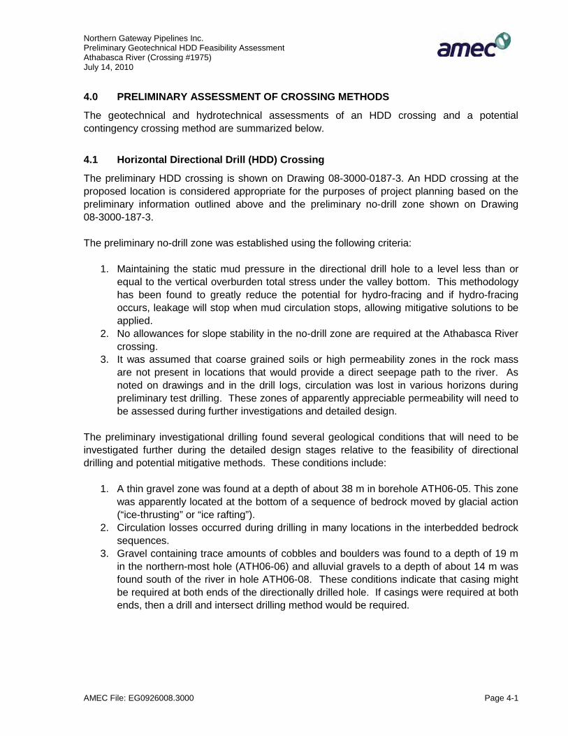
In borehole ATH06-05, north of the river valley, a zone of cobbles was found embedded into a reworked clay shale layer within the bedrock at a depth of 38 m (Photos 9 and 10). A disturbed zone was found at a similar elevation in ATH06-06, north of ATH06-05, and similar lithologies were also encountered in both holes above and below the disturbed zones. Though possessing
Northern Gateway Pipelines Inc.Preliminary Geotechnical HDD Feasibility Assessment Athabasca River (Crossing #1975)July 14, 2010
AMEC File: EG0926008.3000 Page 3-3
similar lithologies, the bedrock above the disturbed zone was different from the bedrock below the disturbed zone, displaying different relative thicknesses and hardnesses of the interbedded layers, differing gradation of the sandstone layers, and differing frequency of high plastic bentonitic layers. The bedrock above the disturbed zone has been interpreted as an ice-thrusted or ice rafted block that was transported some distance by a glacier. The lateral extents of this ice-thrusted block are not currently known.
Colluvium and exposed bedrock were present along the north valley slopes in areas being undercut by the Athabasca River. The colluvium included material derived from the various upland deposits including alluvial fans (consisting of glaciofluvial materials) in some of the gullies and on some parts of the north valley slope.
The valley bottom sediments along the north side of the river included alluvial terraces that occur along the river channels and on low elevation terraces. Two boreholes (ATH06-05, ATH06-06) drilled on the uplands north of the river indicated fluvial and glaciofluvial materials 6 to 8.5 m thick that ranged from sand to cobble sizes. A layer of clay till 6 m deep was encountered underlying the alluvium in ATH06-02 (located 3 km west of the presently proposed route), underlain by bedrock at a depth of 12 m below ground surface. In ATH06-7 (close to thepresently proposed route on the terrace north of the river), the fluvial material was directly underlain by bedrock at a depth of 8.5 m below ground surface.
A variety of deposits underlie the valley bottom south of the river channel, including fine-grainedglaciolacustrine, coarse-grained glaciofluvial, and fine-grained aeolian deposits (Shetson, 1991).Thick accumulations of coarse-textured, sand-dominated outwash deposits were noted in the boreholes drilled on the south side of the river. In particular, sand and gravel deposits extended to depths of 10.5 to 15 m in ATH06-03, ATH06-04, and ATH06-8, underlain by bedrock. This may correspond to the pre-glacial channel noted on the south side of the Athabasca River by Alberta Research Council (1976) at elevations of approximately 670 m or lower. Riverelevations at the time of the site reconnaissance in 2006 were approximately 685 m, suggesting that the pre-glacial channel bed may be within about 15 to 30 m below surface south of the river. None of the holes encountered cobbles or boulders on the bedrock surface; however, such accumulations have been seen along the bottoms of other preglacial channels in Alberta and BC and cannot be ruled out in the Athabasca valley.
The bedrock along the north side of the river and underlying the river varies from west to east and also from north to south. While the exact locations of the mapped boundaries vary amongreferences, Hamilton et al. (1991), Dawson et al. (1998) and AMEC (2001) all map various formations along the valley, with Lower Scollard Formation occurring to west of the general crossing area and formations underlying the Scollard Formation (Wapiti Formation or Horseshoe Canyon equivalent formations) occurring to the east. The Lower Scollard Formation consists of grey feldspathic sandstone, dark grey bentonitic mudstone and thick coal beds. The underlying Wapiti Formation includes rocks of the Edmonton Group and Belly River Group in areas where the intervening Bearpaw Formation is absent, resulting in the two remaining formations being difficult to distinguish.
Northern Gateway Pipelines Inc.Preliminary Geotechnical HDD Feasibility Assessment Athabasca River (Crossing #1975)July 14, 2010
AMEC File: EG0926008.3000 Page 3-4
AMEC (2001) used geophysics well log data to differentiate the rock types within the Wapiti Formation and considered that Upper Horseshoe Canyon Formation occurs east of the Scollard Formation. The Upper Horseshoe Canyon Formation consists of grey sandstone and siltstone with coal seams. There appears to be less bentonitic mudstone present in this formation than in the underlying Middle Horseshoe Canyon that occurs farther to the east. Bedrock cliffs, apparently of sandstone, occur east (downstream) along the north side of the river and may be Upper Horseshoe Canyon Formation.
The variation in bedrock types and properties, upstream and downstream (west and east) of the crossing, appears to be consistent with the lateral variation in stability along the north side of the river. There are several deep-seated slides west of Rev R (Drawing 08-3000-0187-3), an areawhich is thought to be underlain by the Lower Scollard Formation. The Scollard Formation contains frequent high plastic clay or mudstone layers and numerous deep-seated slides occur in this formation. No deep-seated landslides have been identified at the Rev R alignment. This change is apparently due to the improved bedrock conditions in the Upper Horseshoe Canyon (equivalent) unit mapped by AMEC (2001).
3.4 Slope Stability
Widespread evidence of instability in the form of deep-seated slides has been identified on the north slope of the Athabasca River. The Rev R alignment routing was selected to avoid deep-seated landslides and slope instabilities 300 m to the west and further west at previouslyconsidered alignments. To the east, the north slope along the river becomes steep and cliffbands are present. The change in stability conditions from the deep-seated sliding that occurs to the west appears to be due to the change in bedrock formations from the Lower Scollard Formation to the Horseshoe Canyon Formation, as discussed above.
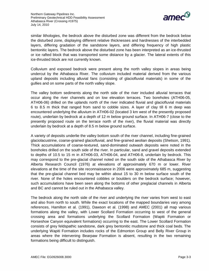
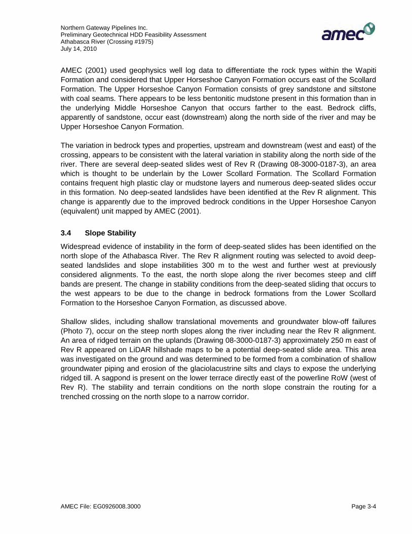
Shallow slides, including shallow translational movements and groundwater blow-off failures(Photo 7), occur on the steep north slopes along the river including near the Rev R alignment.An area of ridged terrain on the uplands (Drawing 08-3000-0187-3) approximately 250 m east of Rev R appeared on LiDAR hillshade maps to be a potential deep-seated slide area. This area was investigated on the ground and was determined to be formed from a combination of shallowgroundwater piping and erosion of the glaciolacustrine silts and clays to expose the underlying ridged till. A sagpond is present on the lower terrace directly east of the powerline RoW (west of Rev R). The stability and terrain conditions on the north slope constrain the routing for a trenched crossing on the north slope to a narrow corridor.

Northern Gateway Pipelines Inc.Preliminary Geotechnical HDD Feasibility Assessment Athabasca River (Crossing #1975)July 14, 2010
AMEC File: EG0926008.3000 Page 3-5
The southern valley slope, approximately 7 km southeast of the crossing location, consists of subdued slopes believed to include remnant ancient deep-seated slide scarps. The surfaces of these features have been obscured by more recent shallow instabilities. To date, no indications of deep-seated movements have been identified in this area (based on helicopter reconnaissance).
3.5 Stream Characteristics
3.5.1 Channel DescriptionThe Athabasca River has a meandering channel that alternates between sinuous and split channel forms. Airphotos show numerous islands, mid-channel bars and point bars along the channel. Near the proposed crossing, the channel is bordered on the north bank by the valley wall, which rises approximately 65 m above the river. On the south side, the river is bordered by a broad, flat floodplain that extends up to about 2 km or more from the edge of the channel to the south valley slopes.
Airphotos taken in 1925 were compared to satellite imagery and LiDAR from 2005/2006 to review channel changes. Over the 80-year period, numerous changes in the channels have occurred throughout the 8 km reach between the McLeod River confluence and about 1 km downstream of the proposed crossing site. Large areas along the south bank have been filled in with sediment, and mid-channel bars that were relatively low and small in the 1920s have been enlarged, raised and vegetated. Over the same period, the south bank, approximately 3 kmupstream of the crossing, has been eroded by up to 150 m at two locations and a 60 m wide subchannel has been established along the south bank just downstream of the proposed crossing.
The evolution of the river channel is typical of a gravel bed river with a large sediment supply.On the scale of a geologic time span, the channel is degrading; however, over a shorter timeframe, such as the life of the proposed pipeline, the channel is expected to be neither aggrading nor degrading. Further review of the channel characteristics is recommended when detailed survey data is available.
3.5.2 River Characteristics at Proposed CrossingThe main channel at the crossing is approximately 260 m wide. On the north bank, a low 90 mwide terrace separates the main river channel from the toe of the valley wall. The floodplain on the south side extends more than 1.5 km to the south valley wall and is used primarily for agricultural purposes.
A local access road located about 500 m south of the main channel roughly parallels the south bank of the river. Airphotos from 1925 show that several large distributary channels existed in the area north of the present road. Since then, the area between the road and the main channel has been infilled with sediment. Several historic subchannels and flood channels are visible on recent aerial imagery and some of the channels have been confirmed in the field to be active.

Northern Gateway Pipelines Inc.Preliminary Geotechnical HDD Feasibility Assessment Athabasca River (Crossing #1975)July 14, 2010
AMEC File: EG0926008.3000 Page 3-6
The largest of the subchannels is located immediately north of the road (Photo 1). This channel is approximately 20 m wide, with steep banks extending up to 5 m above the water surface in the sub-channel. The water depth in the channel has not been measured, but is estimated to be in the order of 2 m. Beaver dams were observed along the subchannel upstream of the proposed crossing. The proposed crossing is located near the confluence of this subchannel with a second subchannel almost equal in size. North of the southernmost subchannel, the proposed alignment crosses one additional historic flood channel that is now mostly infilled (Photos 1 and 3).
The south bank of the Athabasca River is actively eroding approximately 1.2 km upstream of the crossing. While this erosion does not directly affect bank stability at the proposed crossing at this time, ongoing erosion could lead to reactivation of existing subchannels and flood channels between the road and the main channel, which could have implications for a pipeline crossing the river at the crossing location.
The above information and assessment indicates that the Athabasca River is laterally unstable at the proposed crossing, particularly along the south bank. Lateral channel stability is discussed in greater detail below.
Figure 1 shows monthly flows at the crossing predicted on the basis of a nearby gauge. All flows(even minimum flows) are above those for which isolated stream crossing methods can be considered. Diversion methods could be considered by opening up and widening one or more of the subchannels; however, this is not recommended due to the difficulty of returning the river system to its present configuration.

Northern Gateway Pipelines Inc.Preliminary Geotechnical HDD Feasibility Assessment Athabasca River (Crossing #1975)July 14, 2010
AMEC File: EG0926008.3000 Page 3-7
Jan Feb Mar Apr May Jun Jul Aug Sep Oct Nov DecMinimum 47.4 47.6 37.6 79.7 228 476 449 314 190 124 75.7 54.0Average 70.0 66.9 66.7 176.9 409.2 738.0 725.2 512.9 340.2 220.9 126.1 85.9Maximum 133 87.1 118 299 752 1215 1295 812 592 389 203 180
0
200
400
600
800
1000
1200
1400
Mea
n M
onth
ly D
isch
arge
(m
3 /s)
ATHABASCA RIVER AT CROSSING 1975
Discharges at crossing estimated from recorded discharges at WSC Station 07AE001 (Athabasca River near Windfall) and Station 07AD002 (Athabasca River at Hinton).
Figure 1: Mean Monthly Flows of Athabasca River at Crossing

Northern Gateway Pipelines Inc.Preliminary Geotechnical HDD Feasibility Assessment Athabasca River (Crossing #1975)July 14, 2010
AMEC File: EG0926008.3000 Page 3-8
3.5.3 Lateral Channel StabilityThe main channel of the Athabasca River is considered to be laterally unstable at the proposedcrossing, as discussed above. Depending on alignment changes upstream of the crossing due to sediment deposition and erosion, the channel could shift either north or south. The extent to which the channel could migrate northward is limited by the valley wall, located approximately 90 m north of the present north channel bank. On the south side of the channel, southward migration of the channel could extend as far south as approximately the access road, or about 500 m from the present location of the south channel bank. Based on existing erosion and deposition patterns upstream of the crossing, southward migration of the channel is considered to be more likely than northward migration.
Based on traces of historic flood scars and overland flow paths visible on aerial imagery of the site, it is considered unlikely (but not completely out of the question) that the river would migrate even farther south over the next 30 or so years, that is south of the access road. If such migration became apparent, it is anticipated that river engineering works would be undertaken to prevent the migration in order to protect existing infrastructure and development (i.e., local farmresidences and associated buildings, the access road, the power line crossing, etc.).
Based on the above, the Athabasca River could reasonably shift its position anywhere between the toe of the north valley wall and the access road located about 500 m south of the existing channel. The pipelines should be installed below the depth of anticipated scour across this extent.
3.5.4 Depth of ScourDetailed hydrographic data pertaining directly to the Rev R crossing alignment are currently very limited. General channel characteristics were inferred from the available sources and extrapolated to the crossing site. The following parameters were estimated on the basis of the available data and may vary from actual values:
Main channel width 260 m (from LiDAR) Main channel normal depth of flow 2 mBank height (above normal water surface) 3 to 4 mChannel slope 0.0014Main channel average depth for 1:100-year flood 4.1 mSouth subchannel width 25 mSouth subchannel normal depth of flow 2 mBank height (above normal water surface) 4 m

Northern Gateway Pipelines Inc.Preliminary Geotechnical HDD Feasibility Assessment Athabasca River (Crossing #1975)July 14, 2010
AMEC File: EG0926008.3000 Page 3-9
The estimated 1:100-year discharge for the Athabasca River at the crossing is 3020 m3/s. Detailed hydrotechnical studies have not been done at the proposed crossing. There are some uncertainties regarding elevations and other river hydrology parameters both locally and with respect to upstream flood studies. Based on the channel dimensions given above, the flow during an open water flood event might not be contained within the main channel and subchannels and inundation of overbank areas might occur. During an extreme ice jam event,water levels could be higher than for the design open water event, and additional flooding south of the access road might occur.
Scour depths for the 1:100-year flood were estimated using several methods. Due to the uncertainty associated with the below-water channel geometry, the estimated depths of scour derived using the different methods varied between 2 m and 4 m below the channel bed.
Northern Gateway Pipelines Inc.Preliminary Geotechnical HDD Feasibility Assessment Athabasca River (Crossing #1975)July 14, 2010
AMEC File: EG0926008.3000 Page 4-1
4.0 PRELIMINARY ASSESSMENT OF CROSSING METHODS
The geotechnical and hydrotechnical assessments of an HDD crossing and a potential contingency crossing method are summarized below.
4.1 Horizontal Directional Drill (HDD) Crossing
The preliminary HDD crossing is shown on Drawing 08-3000-0187-3. An HDD crossing at the proposed location is considered appropriate for the purposes of project planning based on the preliminary information outlined above and the preliminary no-drill zone shown on Drawing 08-3000-187-3.
The preliminary no-drill zone was established using the following criteria:
1. Maintaining the static mud pressure in the directional drill hole to a level less than or equal to the vertical overburden total stress under the valley bottom. This methodology has been found to greatly reduce the potential for hydro-fracing and if hydro-fracing occurs, leakage will stop when mud circulation stops, allowing mitigative solutions to be applied.
2. No allowances for slope stability in the no-drill zone are required at the Athabasca River crossing.
3. It was assumed that coarse grained soils or high permeability zones in the rock massare not present in locations that would provide a direct seepage path to the river. As noted on drawings and in the drill logs, circulation was lost in various horizons during preliminary test drilling. These zones of apparently appreciable permeability will need to be assessed during further investigations and detailed design.
The preliminary investigational drilling found several geological conditions that will need to be investigated further during the detailed design stages relative to the feasibility of directional drilling and potential mitigative methods. These conditions include:
1. A thin gravel zone was found at a depth of about 38 m in borehole ATH06-05. This zone was apparently located at the bottom of a sequence of bedrock moved by glacial action (“ice-thrusting” or “ice rafting”).
2. Circulation losses occurred during drilling in many locations in the interbedded bedrock sequences.
3. Gravel containing trace amounts of cobbles and boulders was found to a depth of 19 m in the northern-most hole (ATH06-06) and alluvial gravels to a depth of about 14 m was found south of the river in hole ATH06-08. These conditions indicate that casing might be required at both ends of the directionally drilled hole. If casings were required at both ends, then a drill and intersect drilling method would be required.

Northern Gateway Pipelines Inc.Preliminary Geotechnical HDD Feasibility Assessment Athabasca River (Crossing #1975)July 14, 2010
AMEC File: EG0926008.3000 Page 4-2
Further field studies should be carried out to investigate geotechnical conditions with respect to:
1. Depth, lithology and lateral distribution of deposits underlying the valley within the approximate lateral limits of the HDD path adjacent to the river.
2. Permeability conditions in both the bedrock and overburden.3. Surficial geology within the local area of the crossing. 4. The buried surface profile and geological characteristics of the underlying bedrock.5. Scour and lateral erosion.
An HDD crossing is feasible from a hydrotechnical point-of-view.
4.2 Contingency Crossing Method
The presently identified contingency crossing method for the Athabasca River is a trenched crossing. Considerations for this crossing method include lateral erosion and scour. The route on the north valley slope would require grading, and ground and surface water control and drainage to mitigate the piping erosion that is occurring in some locations.

Northern Gateway Pipelines Inc.Preliminary Geotechnical HDD Feasibility Assessment Athabasca River (Crossing #1975)July 14, 2010
AMEC File: EG0926008.3000 Page 5-1
5.0 FUTURE GEOTECHNICAL WORK TO SUPPORT DETAILED DESIGN
1. Carry out hydrotechnical and geotechnical ground reconnaissances in the proposed crossing area. Specific areas of interest include updating groundwater conditions on the north valley slope, lateral erosion and scour.
2. Obtain survey data across the channel as required for scour modelling and to indicate the channel bottom accurately on cross sections.
3. Complete a combined drilling investigation and geophysical survey to determine subsurface geological conditions. Measurement of permeability will be considered.
4. Conduct a hydrotechnical investigation at the site, including a channel stability assessment, scour assessment if required by crossing method considerations and stream flow measurement.
5. Provide a combined hydrotechnical and geotechnical report on crossing feasibility.

Northern Gateway Pipelines Inc.Preliminary Geotechnical HDD Feasibility Assessment Athabasca River (Crossing #1975)July 14, 2010
AMEC File: EG0926008.3000 Page 6-1
6.0 CLOSURE
Recommendations presented herein are based on a geotechnical evaluation of the findings of the site investigation noted and other information as discussed in the report. This report is preliminary and recommendations contained herein should be updated and revised as additional information becomes available from further investigations.
This report has been prepared for the exclusive use of Northern Gateway Pipelines Inc. for specific application to the area within this report. Any use which a third party makes of this report, or any reliance on or decisions made based on it, are the responsibility of such third parties. AMEC accepts no responsibility for damages, if any, suffered by any third party as aresult of decisions made or actions based on this report. It has been prepared in accordance with generally accepted geotechnical engineering practices. No other warranty, expressed or implied, is made.
Respectfully submitted,
AMEC Earth & Environmental,a division of AMEC Americas Limited Reviewed by:
PerD.S. (Drum) Cavers, M.Eng., P.Eng.Principal Engineer
Pete Barlow, M.Sc., P.Eng.Principal Geotechnical Engineer
Original paper copies signed and sealed
by D.S. Cavers, M.Eng., P.Eng., P.Geo.

Northern Gateway Pipelines Inc.Preliminary Geotechnical HDD Feasibility Assessment Athabasca River (Crossing #1975)July 14, 2010
AMEC File: EG0926008.3000 Page 6-2
REFERENCES
Alberta Research Council. 1976. Carlson, WAD. 1972, revised by R. Green. 1976. Bedrock Topography of the Whitecourt Area, Alberta, (NTS 83J). 1:250,000 scale.
AMEC Earth & Environmental. 2001. Regional Groundwater Assessment, Woodlands County, Part of the Athabasca River Basin. Includes Part or All of Tp. 056 To 065, Rg. 04 To 13, W5m.http://www.agr.gc.ca/pfra/water/reports/woodld.pdf
Dawson, F.M., C.G. Evans, R. March and R. Richardson. 1998, Uppermost Cretaceous and Tertiary Strata of the Western Canada Sedimentary Basin. In Geological Atlas on the Western Canada Sedimentary Basin. G.D. Mossop and I. Shetson (comps.). On-line version: http://www.ags.gov.ab.ca/AGS_PUB/ATLAS_WWW/A_CH30/CH30.HTM.
Hamilton, W.N., M.C. Price, and G.W. Logen Berg. 1991. Geological Map of Alberta. Alberta Geological Survey, Alberta Energy and Utilities Board. Map No. 236. 1:1,000,000 scale.
Shetson, I. 1990. Quaternary geology of central Alberta. Alberta Research Council, Natural Resources Division, Terrain Sciences Department map. 1:500,000 scale.

Photos 1 to 5
PROJECT No: EG0926008.3000.0187
PREPARED BY: S. HORSLEY
REVISION: 1
DATE PREPARED: MARCH 2010 Preliminary Geotechnical Report on
Potential Crossing Methods Athabasca River (Crossing #1975)
Taken: 2006, 2008
Photo 1: View of Athabasca River looking northwest. Note location of sub-channels on the south side of the river, and deep seated slide block on the north side.
AMEC Earth & Environmental 2227 Douglas Road
Burnaby, BC, CANADA, V5C 5A9 Tel. (604) 294-3811 Fax. (604) 294-4664
NOTE: THIS DRAWING SHOULD BE READ IN CONJUNCTION WITH THE APPLICABLE AMEC EARTH & ENVIRONMENTAL REPORT ON ATHABASCA RIVER.
Photo 2: Athabasca River looking west. Note deep seated slide block and erosional terrace features on the north slope. The locations of boreholes are also shown.
Photo 4: Looking west at the north bank of the Athabasca River. Gullies are present on the slope and were formed in part by groundwater piping events (blow-off failures). Rock cliff bands occur along the slope east of the Rev R centerline.
Photo 5: Looking east on the north bank through the forest on the uplands above the slope. LiDAR hillshade models showed several lineaments that could be slide scarp features. Ground inspections revealed the features to be buried till ridges exposed and augmented by piping erosion through the sandier glaciolacustrine deposits blanketing the till near the river.
Photo 3: Athabasca River side channels on south bank looking east. Multiple side channels are identified in the picture. A local road that could be used for access to the site is visible on the right (south) side of the photo.

Photos 6 to 10
PROJECT No: EG0926008.3000.0187
PREPARED BY: S. HORSLEY
REVISION: 1
DATE PREPARED: MARCH 2010 Preliminary Geotechnical Report on
Potential Crossing Methods Athabasca River (Crossing #1975)
Taken: 2006
AMEC Earth & Environmental 2227 Douglas Road
Burnaby, BC, CANADA, V5C 5A9 Tel. (604) 294-3811 Fax. (604) 294-4664
NOTE: THIS DRAWING SHOULD BE READ IN CONJUNCTION WITH THE APPLICABLE AMEC EARTH & ENVIRONMENTAL REPORT ON ATHABASCA RIVER.
Photo 7: Looking north at a groundwater blow-off failure in a gully on the north approach slope. Drainage and grading will be required on the north approach slope in order to construct a trenched pipeline.
Photo 8: Interbedded sandstone and siltstone located near the toe of the northern approach slope. Similar outcrops were observed in numerous locations along the base of the slope. The bedrock conditions are highly variable due to ice thrusting, and the bedrock formations present.
Photo 6: Looking at tree roots exposed by piping in sandy silt glaciolacustrine deposits in the area of lineations on the LiDAR. Roots in this area of forest had often been exposed by piping erosion.
Photo 9: Cobble and gravel sized material embedded into clay shale core from ATH06-06. This zone of quartzite gravel/cobbles may indicate the lower boundary of an ice-thrust block of bedrock.
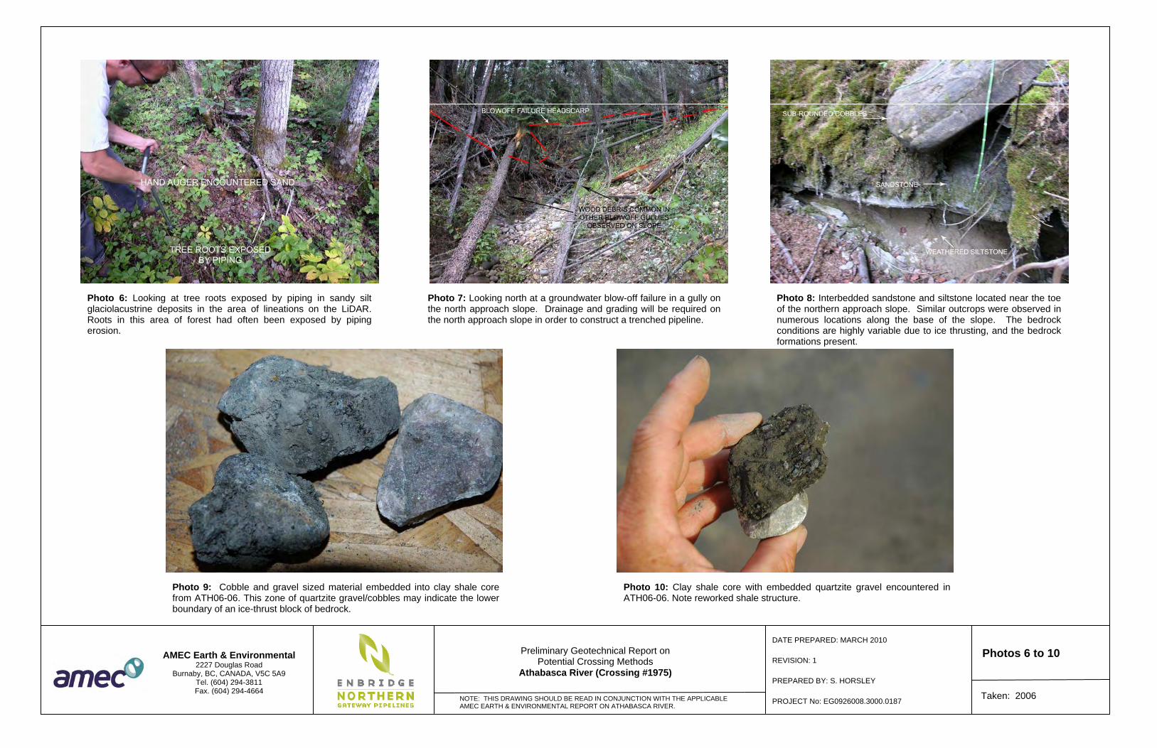
Photo 10: Clay shale core with embedded quartzite gravel encountered in ATH06-06. Note reworked shale structure.


�������
��
���� ��������� ��� ������������� �
������ ����������������� �� �!"#�$�%�&'(����)���*�+�,-(������!.#/
�(0���,����-)��1&��(-&�� 1��
�&2��(��&�
��)-,-&���&�
3-4'����&�
,0��(��&�
��(�
!��5�!
(-(1�
�&2��(-&�
��('�
&�-4-��1�,��1�
����"6
'(��7����!!
�,�,0&��� ����4�
8
$
/
9
!
6
����) -,,'����)-,-&����,��- (-&�
������������
�����������������������
&)��)-���+����1&��(-&�,
:� !/::!:::/:: 9:::
999#���;<� =��� �>��;�� ?@>�����>�)/��/�.(����8:$+9.$+6"!!��3 A�8:$+9.$+$88$
�&2��(
��1-�-����4�&(��0�-��1�3��,��-1-(��� &�( �& &,���0�����(���&'�,����&,,-�4
���9:!:
�4:.98::"�6:::�:!"#
:
:"+6:::+:!"#+!
(�,�
�,�:/9/: 9:!: -,,'���3&��3-1-�4
����-�4���&�(0����4�(���� �&2��(
,��,�
��3������,
�-4-(�1���,��+�!/:>:::��(,�, ��(�'���-4-(�1�-��4-�4� �& &,��� - �1-����1-4����(�+�B��)+�B>�2'1�9::.>��&�1� ��,&�,��14��
����-�4�(&���������-���&�2'��(-&���-(0���������(0����)-�&����(�1��� &�(�&���(0���,����-)���0���
�������������������� !!"������#���
�0�B���
,�>��,�


APPENDIX A
Drill Logs


DEPT
H (m
)
Lost circulation at 8.5m
Drilled with heavy drill mud,partial circulation at 9.3m
SOILDESCRIPTION
0
SPLIT SPOON
Drilled with 145 mm tricone bit
D1
1
2
3
4
5
6
7
8
9
TUBE
CLAY, silty, trace to some sand, intermediate to high plasticity,brown
D2
D3
Lost water, approximately 10 L/m
Frozen to 0.3m- at 0.3 m, stiff
- at 1.8 m, mottled brown and grey
SAND, fine-grained, silty, compact, uniformly graded, brown
CLAY, silty, sandy, trace gravel, trace cobbles, intermediateplasticity, very stiff, grey to brown, slight oxidation, sand inclusions[TILL]
GRAVEL, sandy, silty, trace clay, brown
- below 9.3 m, some sand, gravel sizes from 12 to 25 mmdiameter, trace boulders, sub angular to angular
CORE RETURN
DEPT
H (m
)
SAMP
LE T
YPE
NO RECOVERY
COMPLETION DEPTH: 124.8 mCOMPLETION DATE: 3/11/06
SAMP
LE N
O
GRAB
BOREHOLE NO: ATH06-01PROJECT NO: EG0926008.3000.0187ELEVATION:
RQD
(%)
BH
FO
R S
OIL
/RO
CK
EG
0926
008.
3000
.018
7-A
THA
BA
SC
A R
IVE
R C
RO
SS
ING
.GP
J A
ME
C-E
&E
.BC
-MU
LTIW
ELL
-DA
TATE
MP
LATE
-RE
V1.
GD
T 1
/27/
09
20 40 60 80SPT "N" (BLOWS/300 mm)
ADDITIONALINFORMATION
1
2
3
4
5
6
7
8
9
CLIENT: Enbridge Northern Gateway Pipeline LP.DRILLER: Garritty & Baker DrillingDRILL TYPE/METHOD: Track Mayhew 1000/Wet Rotary
Page 1 of 13
MUD RETURN
RECO
VERY
(%)
10
SAMPLE TYPE
AMEC Earth & Environmental3456 Opie CrescentPrince George, BC V2N 2P9Tel: (250) 564-3243
PROJECT: Athabasca River CrossingAthabasca River CrossingNORTHING: 6002887 EASTING: 590290
SOIL
SYMB
OL
LOGGED BY: CRAENTERED BY: HR
00
1
2
3
4
5
6
7
8
9

TUBE SPLIT SPOON
DEPT
H (m
)
11
12
13
14
15
16
17
18
19
SAMP
LE T
YPE
AMEC Earth & Environmental3456 Opie CrescentPrince George, BC V2N 2P9Tel: (250) 564-3243
CLIENT: Enbridge Northern Gateway Pipeline LP.DRILLER: Garritty & Baker DrillingDRILL TYPE/METHOD: Track Mayhew 1000/Wet Rotary
C1
- from 18.7 to 18.9 m, dark brown, highly carbonaceous,slickensided, fissile, easily crumbled
92
GRAVEL, sandy, silty, trace clay, brown (continued)
- at 12.2 m, sandy, fine- to coarse-grained, dense
- at 12.8 m, interlayered sand and gravel, 300 to 450mm thick,dense to very dense
SHALE
- below 18.3 m, extremely weak (R0), blocky breakage, fissile,trace dark brown carbonaceous interbeds, crushed, fragments upto 60mm diameter
- below 18.9 m, fractured to blocky
23
Casing installed to 17.0 m
SOILDESCRIPTION
10
MUD RETURN
weathered, grey
11
12
13
14
15
16
17
18
19
SAMP
LE N
O
GRAB
BOREHOLE NO: ATH06-01PROJECT NO: EG0926008.3000.0187ELEVATION:
RQD
(%)
BH
FO
R S
OIL
/RO
CK
EG
0926
008.
3000
.018
7-A
THA
BA
SC
A R
IVE
R C
RO
SS
ING
.GP
J A
ME
C-E
&E
.BC
-MU
LTIW
ELL
-DA
TATE
MP
LATE
-RE
V1.
GD
T 1
/27/
09
20 40 60 80SPT "N" (BLOWS/300 mm)
COMPLETION DEPTH: 124.8 mCOMPLETION DATE: 3/11/06
10
Page 2 of 13
ADDITIONALINFORMATION
PROJECT: Athabasca River CrossingAthabasca River CrossingNORTHING: 6002887 EASTING: 590290
10
DEPT
H (m
)
LOGGED BY: CRAENTERED BY: HR
SOIL
SYMB
OL
RECO
VERY
(%)
SAMPLE TYPE
20
NO RECOVERY CORE RETURN
11
12
13
14
15
16
17
18
19

very weak (R1), occasional weathered zones, carbonaceous darkbrown interbeds, up to 300mm thick- from 29.1 to 29.2 m, extremely weak (R0), dark grey claystoneinterbeds
66
85
82fine-grained, weak (R2), grey
20
SANDSTONE
TUBE
C2
DEPT
H (m
)
21
22
23
24
25
26
27
28
29
SOILDESCRIPTION
SHALE (continued)
C3
C4
100
100
100
SHALE
- from 21.7 to 22.0 m, highly carbonaceous, fissile with thin coallaminations and lenses, up to 30mm thick- below 22.0 m, grey, blocky, thin siltstone interbeds up to 100 mmthick
- from 24.8 to 25.0 m, highly carbonaceous, fissile, dark brown,occasional slickensides (multi-directional)- at 25.0 m, grey to greenish grey
- from 25.5 to 25.8 m, very weak (R1)
- below 25.9 m, healed joints
- from 27.0 to 27.5 m, highly carbonaceous, extremely weak (R0)to very weak (R1), dark brown, joints: 40° to 70° dip, slickensided
- at 27.5 m, greenish grey, interbedded dark brown carbonaceouszones- from 27.5 to 27.8 m, weak (R2), fissile, slickensided- from 27.8 to 28.9 m, very weak (R1), blocky, extremely weak(R0) zones, up to 50mm thick, slickensided
SILTSTONEwell cemented, grey
COMPLETION DEPTH: 124.8 mCOMPLETION DATE: 3/11/06
NO RECOVERY CORE RETURN
DEPT
H (m
)
SAMP
LE N
O
SPLIT SPOON
30
GRAB
BOREHOLE NO: ATH06-01PROJECT NO: EG0926008.3000.0187ELEVATION:
RQD
(%)
BH
FO
R S
OIL
/RO
CK
EG
0926
008.
3000
.018
7-A
THA
BA
SC
A R
IVE
R C
RO
SS
ING
.GP
J A
ME
C-E
&E
.BC
-MU
LTIW
ELL
-DA
TATE
MP
LATE
-RE
V1.
GD
T 1
/27/
09
20 40 60 80SPT "N" (BLOWS/300 mm)
Page 3 of 13
CLIENT: Enbridge Northern Gateway Pipeline LP.DRILLER: Garritty & Baker DrillingDRILL TYPE/METHOD: Track Mayhew 1000/Wet Rotary
MUD RETURN
21
22
23
24
25
26
27
28
29
SAMP
LE T
YPE
SAMPLE TYPE
AMEC Earth & Environmental3456 Opie CrescentPrince George, BC V2N 2P9Tel: (250) 564-3243
20
RECO
VERY
(%)
LOGGED BY: CRAENTERED BY: HR
20
21
22
23
24
25
26
27
28
29
PROJECT: Athabasca River CrossingAthabasca River CrossingNORTHING: 6002887 EASTING: 590290
ADDITIONALINFORMATION
SOIL
SYMB
OL

Lost water, approximately 33 L/m
DEPT
H (m
)
SANDSTONEfine-grained, moderately cemented, very weak (R1), blue grey,siltstone interbeds- from 38.6 to 39.1 m, dark grey- from 39.1 to 40.5 m, interbedded grey siltstone and claystone,striated
SILTSTONE
85
79
89
Point Load Test: UC Axial = 1.1 MPa UC Diametral = 0.1 MPa
- below 37.5 m, claystone, very weak (R1), dark brown, slightlycarbonaceous, occasional isolated slickensides
Point Load Test: UC Axial = 5.1 MPa UC Diametral = 1.1 MPa
- from 36.6 to 37.5 m, interbedded, grey to dark grey siltstone,strong (R4) to very strong (R5), fine-grained sandstone andmedium plastic silty clay, striated
Point Load Test: UC Axial = 7.3 MPa UC Diametral = 1.1 MPa
Point Load Test: UC Axial = 13.0 MPa UC Diametral = 4.5 MPa
Point Load Test: UC Axial = 7.9 MPa UC Diametral = 2.3 MPa
Lost water, approximately 33 L/m
C5
30
TUBE SPLIT SPOON
Lost water, approximately 16 L/m
- from 29.2 to 29.5 m, siltstone, strong (R4), indurated, dark grey
C6
C7
100
100
100- from 38.3 to 38.5 m, dark greenish grey and dark brown,carbonaceous
SHALE (continued)
- from 29.7 to 29.9 m, dark grey with light brown, carbonaceous,medium strong (R3) to strong (R4), laminations- from 30.1 to 30.3 m, lenses of siltstone and mudstone, very weak(R1), striated- from 30.3 to 30.5 m, grey, blocky- at 30.5 m, carbonaceous, dark brown- from 30.5 to 30.7 m, highly carbonaceous mudstone, weak (R2)- at 30.6 m, slickensided, subvertical- from 30.7 to 31.0 m, grey to greenish grey, bentonitic, blocky
- at 31.9 m, bentonite seam: intermediate to low plastic, tan,lenticular, 20mm to 50mm thick- from 31.9 to 33.2m, joints: 20 to 90° dip, slickensided, closespacing- at 32.0 m, bentonitic, grey to greenish grey- from 32.2 to 32.6 m, greenish grey- from 32.6 to 33.2 m, very weak (R1) to weak (R2),carbonaceous, dark brown- from 33.2 to 33.9 m, bentonitic, very weak (R1), greenish grey
- from 33.9 to 35.4 m, very weak (R2) to weak (R3), grey, with wetjoints
- from 35.4 m to 35.8 m, sandstone, fine-grained, weak (R2) tomedium strong (R3), dark grey
- from 35.8 to 36.6 m, claystone, grey to dark grey
SAMPLE TYPE
40
CORE RETURN
SOILDESCRIPTION
SAMP
LE N
O
NO RECOVERY
COMPLETION DEPTH: 124.8 mCOMPLETION DATE: 3/11/06
GRAB
BOREHOLE NO: ATH06-01PROJECT NO: EG0926008.3000.0187ELEVATION:
RQD
(%)
BH
FO
R S
OIL
/RO
CK
EG
0926
008.
3000
.018
7-A
THA
BA
SC
A R
IVE
R C
RO
SS
ING
.GP
J A
ME
C-E
&E
.BC
-MU
LTIW
ELL
-DA
TATE
MP
LATE
-RE
V1.
GD
T 1
/27/
09
20 40 60 80SPT "N" (BLOWS/300 mm)
31
32
33
34
35
36
37
38
39
SAMP
LE T
YPE
DEPT
H (m
)
RECO
VERY
(%)
AMEC Earth & Environmental3456 Opie CrescentPrince George, BC V2N 2P9Tel: (250) 564-3243
PROJECT: Athabasca River CrossingAthabasca River CrossingNORTHING: 6002887 EASTING: 590290
SOIL
SYMB
OL
LOGGED BY: CRAENTERED BY: HR
30
CLIENT: Enbridge Northern Gateway Pipeline LP.DRILLER: Garritty & Baker DrillingDRILL TYPE/METHOD: Track Mayhew 1000/Wet Rotary
31
32
33
34
35
36
37
38
39
ADDITIONALINFORMATION
Page 4 of 13
31
32
33
34
35
36
37
38
39
MUD RETURN
30

SOILDESCRIPTION
95
66
100
Point Load Test: UC Axial = 7.3 MPa UC Diametral = 5.6 MPa
Lost water, approximately330 L/m
Point Load Test: UC Axial = 7.1 MPa UC Diametral = 4.0 MPa
Lost water, approximately40 L/m, possible mud ringsforming
Point Load Test: UC Axial = 3.4 MPa UC Diametral = 1.1 MPa
Lost water, approximately170 L/m
Point Load Test: UC Axial = 1.1 MPa UC Diametral = 0.6 MPa
41
42
43
44
45
46
47
48
49
- from 47.5 to 47.7 m, joints: subvertical, slickensided
40
TUBE
C8
DEPT
H (m
)
very weak (R1), grey, interbedded with thin shale seams
C9
C10
100
100
100
SILTSTONE (continued)
- below 48.5 m, grey to brown
SANDSTONEfine-grained, moderately cemented, very weak (R1), blue grey- from 40.5 to 43.2 m, massive, uniform, black and white
SHALEbentonitic, very weak (R1), dark brown, massive, healed fractures,waxy- from 43.4 to 47.7 m, joints: 30° to 80° dips, occasionallyslickensided, moderately close spacing
- below 45.7 m, carbonaceous, dark brown- from 45.9 to 46.3 m, bentonite seam, hard, high plastic, brownishgrey- below 46.2 m, very weak (R1), carbonaceous, grey to darkbrown, fractured- at 46.6 m, bentonite layer, 25 mm thick, brownish grey
- below 46.8 m, carbonaceous, dark brown, waxy, fractured
50
NO RECOVERY CORE RETURNSPLIT SPOON
SAMP
LE N
O
SAMPLE TYPE
DEPT
H (m
)
COMPLETION DEPTH: 124.8 mCOMPLETION DATE: 3/11/06
GRAB
BOREHOLE NO: ATH06-01PROJECT NO: EG0926008.3000.0187ELEVATION:
RQD
(%)
BH
FO
R S
OIL
/RO
CK
EG
0926
008.
3000
.018
7-A
THA
BA
SC
A R
IVE
R C
RO
SS
ING
.GP
J A
ME
C-E
&E
.BC
-MU
LTIW
ELL
-DA
TATE
MP
LATE
-RE
V1.
GD
T 1
/27/
09
20 40 60 80SPT "N" (BLOWS/300 mm) SA
MPLE
TYP
E
AMEC Earth & Environmental3456 Opie CrescentPrince George, BC V2N 2P9Tel: (250) 564-3243
CLIENT: Enbridge Northern Gateway Pipeline LP.DRILLER: Garritty & Baker DrillingDRILL TYPE/METHOD: Track Mayhew 1000/Wet Rotary
MUD RETURN
40
RECO
VERY
(%)
SOIL
SYMB
OL
41
42
43
44
45
46
47
48
49
40
41
42
43
44
45
46
47
48
49
PROJECT: Athabasca River CrossingAthabasca River CrossingNORTHING: 6002887 EASTING: 590290
ADDITIONALINFORMATION
Page 5 of 13
LOGGED BY: CRAENTERED BY: HR

SHALE
COAL
- at 58.5 m, bentonite layer, 40 mm thick, high plastic, light tomedium brown
- below 58.1 m, highly carbonaceous, very weak (R1), dark brown,trace coal fragments
- from 57.8 to 58.1 m, weak (R2)
- from 57.6 to 58.0 m, light brown ironstone layers, 6 mm to 12 mmthick
- at 56.7 m, fine-grained sandstone interbedded with white chertbeds, up to 75 mm thick
SANDSTONE and SILTSTONE
well cemented, very weak (R1), grey, striated
bentonitic, very weak (R1), grey, coal fragments
- from 55.4 to 55.6 m, well cemented, medium strong (R3) tostrong (R4), medium to light grey
fine-grained, very weak (R1), grey, trace tan ironstone inclusionsSANDSTONEvery weak (R1), striated, grey, trace tan ironstone inclusionsSHALE
Point Load Test: UC Axial = 19.2 MPa UC Diametral = 16.4 MPa
- from 56.4 to 56.6 m, joint set: 35° to 40° dip, slickensided, veryclose to close spacing
Lost water, approximately130 L/m
Point Load Test: UC Axial = 7.6 MPa UC Diametral = 4.2 MPa
Lost approximately 200 L, incarbonaceous zone
Lost water, approximately100 L/m, in upper 1 m ofsandstone
49
87
laminated with carbonaceous shale interbeds
SHALE
C11
- at 54.1 m, grey, coal fragments
89
100
100
fine-grained sandstone, moderately cemented, very weak (R1),grey, striated, coal fragments, interbedded
100
C14
C13
C12 100
fine-grained, very weak (R1), grey, black and white, verticalfracture 150 mm long, coal fragments, thin non-cementedinterbeds, up to 15 mm thick
highly carbonaceous, very weak (R1), dark brown, coal fragmentsand interbeds up to 25 mm thick
SHALE
- at 53.3 m, moderately cemented, grey, friable- at 53.2 m, very well cemented, very strong (R5), indurated
- below 52.0 m, moderately cemented, blue grey- at 51.9 m, interbedded with shale, 100 mm thick
- from 50.8 to 53.2 m, easily friable to friable
SANDSTONE
- from 50.5 to 50.8 m, waxy, striated, dark grey
- from 49.9 to 50.5 m, bentonitic, carbonaceous, waxy, darkbrownish grey, joints: subvertical, slickensided
SHALE (continued)
- below 51.5 m, fine-grained, grey, some medium- to fine-grainedinterbeds, trace coal fragments
SAMPLE TYPE
SAMP
LE N
O
CORE RETURN
50
60
RECO
VERY
(%)
SOIL
SYMB
OL
LOGGED BY: CRAENTERED BY: HR
SPT "N" (BLOWS/300 mm) 20 40 60 80
BH
FO
R S
OIL
/RO
CK
EG
0926
008.
3000
.018
7-A
THA
BA
SC
A R
IVE
R C
RO
SS
ING
.GP
J A
ME
C-E
&E
.BC
-MU
LTIW
ELL
-DA
TATE
MP
LATE
-RE
V1.
GD
T 1
/27/
09
RQD
(%)
BOREHOLE NO: ATH06-01PROJECT NO: EG0926008.3000.0187ELEVATION:
COMPLETION DEPTH: 124.8 mCOMPLETION DATE: 3/11/06
NO RECOVERY GRAB
DEPT
H (m
)
51
52
53
54
55
56
57
58
59
TUBE SPLIT SPOON
DEPT
H (m
)
50
51
52
53
54
55
56
57
58
59
PROJECT: Athabasca River CrossingAthabasca River CrossingNORTHING: 6002887 EASTING: 590290
ADDITIONALINFORMATION
Page 6 of 13
MUD RETURN
50
CLIENT: Enbridge Northern Gateway Pipeline LP.DRILLER: Garritty & Baker DrillingDRILL TYPE/METHOD: Track Mayhew 1000/Wet Rotary
AMEC Earth & Environmental3456 Opie CrescentPrince George, BC V2N 2P9Tel: (250) 564-3243
SAMP
LE T
YPE
SOILDESCRIPTION
51
52
53
54
55
56
57
58
59

82
SANDSTONE and SILTSTONEfine-grained sandstone, very weak (R1), grey, interbedded
SHALEvery weak (R1) to weak (R2), light brown ironstone layers, 10 mmthick- at 68.2 m, coal layer, 150 mm thick, flaky, fissile- at 68.4 m, carbonaceous, dark brown, coal fragments
- at 68.9 m, joint: 60° dip, slickensided
- at 66.3 m, siltstone interbed, very weak (R1) to weak (R2)
89
- below 65.9 m, very weak (R1), grey
Point Load Test: UC Axial = 3.4 MPa UC Diametral = 0.8 MPa
Got 20% fluid return on bottom1.5 m of core run, usingapproximately 170 L/m
Point Load Test: UC Axial = 9.6 MPa UC Diametral = 6.8 MPa
C15
SOILDESCRIPTION
TUBE SPLIT SPOON
DEPT
H (m
)
82
SHALE (continued)
C16
C17
100
98
95
- below 66.5 m, very weak (R1), light brown, striated
60
- below 60.3 m, carbonaceous, dark brown- from 60.4 to 60.7 m, joints: 30° to 50° dip, slickensided
- below 62.0 m, carbonaceous, dark brown, trace coal fragments
- below 62.5 m, grey
- at 63.1 m, fine-grained sandstone interbeds, up to 75 mm thick,well cemented
- at 63.5 m, indurated sandstone layer, 100 mm thick, wellcemented- from 63.6 to 64.1 m, light brown ironstone layers, 10 to 30 mmthick, smooth
BENTONITEvery weak (R1), high plastic, white to greenish white, waxy,slickensidedSHALEvery weak (R1), grey- from 64.6 to 65.9 m, joints: slickensided- below 65.1 m, highly carbonaceous, dark brown, trace coalfragments
SAMPLE TYPE
70
NO RECOVERY CORE RETURN
SAMP
LE N
O
DEPT
H (m
)
COMPLETION DEPTH: 124.8 mCOMPLETION DATE: 3/11/06
GRAB
BOREHOLE NO: ATH06-01PROJECT NO: EG0926008.3000.0187ELEVATION:
RQD
(%)
BH
FO
R S
OIL
/RO
CK
EG
0926
008.
3000
.018
7-A
THA
BA
SC
A R
IVE
R C
RO
SS
ING
.GP
J A
ME
C-E
&E
.BC
-MU
LTIW
ELL
-DA
TATE
MP
LATE
-RE
V1.
GD
T 1
/27/
09
20 40 60 80SPT "N" (BLOWS/300 mm) SA
MPLE
TYP
E
AMEC Earth & Environmental3456 Opie CrescentPrince George, BC V2N 2P9Tel: (250) 564-3243
RECO
VERY
(%)
CLIENT: Enbridge Northern Gateway Pipeline LP.DRILLER: Garritty & Baker DrillingDRILL TYPE/METHOD: Track Mayhew 1000/Wet Rotary
ADDITIONALINFORMATION
SOIL
SYMB
OL
LOGGED BY: CRAENTERED BY: HR
6060
61
62
63
64
65
66
67
68
69
61
62
63
64
65
66
67
68
69
PROJECT: Athabasca River CrossingAthabasca River CrossingNORTHING: 6002887 EASTING: 590290
MUD RETURN
Page 7 of 13
61
62
63
64
65
66
67
68
69
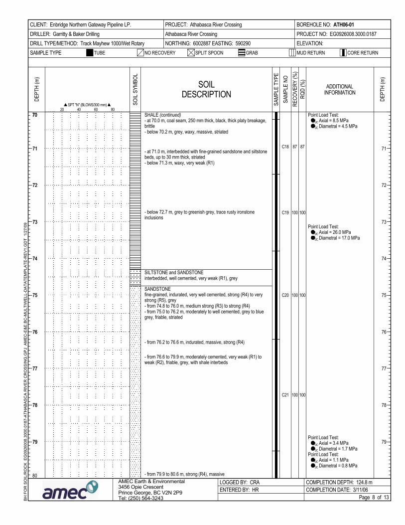
- from 76.6 to 79.9 m, moderately cemented, very weak (R1) toweak (R2), friable, grey, with shale interbeds
- from 79.9 to 80.6 m, strong (R4), massive
87
100
100
100
Point Load Test: UC Axial = 8.5 MPa UC Diametral = 4.5 MPa
Point Load Test: UC Axial = 26.0 MPa UC Diametral = 17.0 MPa
- from 75.0 to 76.2 m, moderately to well cemented, grey to bluegrey, friable, striated
Point Load Test: UC Axial = 1.1 MPa UC Diametral = 0.8 MPa
- from 74.8 to 76.0 m, medium strong (R3) to strong (R4)
SOILDESCRIPTION
70
C18
SPLIT SPOON
DEPT
H (m
)
Point Load Test: UC Axial = 3.4 MPa UC Diametral = 1.7 MPa
C19
C20
C21
87
100
- from 76.2 to 76.6 m, indurated, massive, strong (R4)
100
TUBE
SHALE (continued)- at 70.0 m, coal seam, 250 mm thick, black, thick platy breakage,brittle- below 70.2 m, grey, waxy, massive, striated
- at 71.0 m, interbedded with fine-grained sandstone and siltstonebeds, up to 30 mm thick, striated- below 71.3 m, waxy, very weak (R1)
- below 72.7 m, grey to greenish grey, trace rusty ironstoneinclusions
SILTSTONE and SANDSTONEinterbedded, well cemented, very weak (R1), grey
SANDSTONEfine-grained, indurated, very well cemented, strong (R4) to verystrong (R5), grey
100
80
NO RECOVERY CORE RETURN
DEPT
H (m
)
71
72
73
74
75
76
77
78
79
SAMPLE TYPE
COMPLETION DEPTH: 124.8 mCOMPLETION DATE: 3/11/06
GRAB
BOREHOLE NO: ATH06-01PROJECT NO: EG0926008.3000.0187ELEVATION:
RQD
(%)
BH
FO
R S
OIL
/RO
CK
EG
0926
008.
3000
.018
7-A
THA
BA
SC
A R
IVE
R C
RO
SS
ING
.GP
J A
ME
C-E
&E
.BC
-MU
LTIW
ELL
-DA
TATE
MP
LATE
-RE
V1.
GD
T 1
/27/
09
20 40 60 80SPT "N" (BLOWS/300 mm) SA
MPLE
TYP
E
71
72
73
74
75
76
77
78
79
SAMP
LE N
O
AMEC Earth & Environmental3456 Opie CrescentPrince George, BC V2N 2P9Tel: (250) 564-3243
MUD RETURN
CLIENT: Enbridge Northern Gateway Pipeline LP.DRILLER: Garritty & Baker DrillingDRILL TYPE/METHOD: Track Mayhew 1000/Wet Rotary
ADDITIONALINFORMATION
71
72
73
74
75
76
77
78
79
LOGGED BY: CRAENTERED BY: HR
70
PROJECT: Athabasca River CrossingAthabasca River CrossingNORTHING: 6002887 EASTING: 590290
70
SOIL
SYMB
OL
Page 8 of 13
RECO
VERY
(%)

- from 86.6 to 89.7 m, grey to dark grey
- from 89.7 to 90.1 m, carbonaceous, very weak (R1), dark brown,- at 89.7 m, coal seam, 25 mm thick
- at 86.8 m, dark grey siltstone seam
- from 86.4 to 86.6 m, dark brown, highly carbonaceous, joints:65° dip, slickensided
- at 86.3 m, very weak (R1), brittle, grey, carbonaceous sandstoneinterbeds
- from 86.0 to 86.3 m, coal seam, black, shiny, brittle
- from 84.4 to 86.0 m, weak (R2), dark brown, carbonaceousvery weak (R1) to weak (R2), grey, siltstone laminations, brittleSHALE
- from 89.3 to 89.5 m, joint set: 80° dip, slickensided, closespacing
80
SOILDESCRIPTION
Point Load Test: UC Axial = 6.5 MPa UC Diametral = 2.3 MPa
Used approximately 600 L/m ofwater for 27 m of drilling, someloss of return circulation
fine-grained, well cemented, weak (R2), grey, light brownironstone nodules, trace coal fragments
Point Load Test: UC Axial = 113.1 MPa UC Diametral = 84.8 MPaC22
72
100
100
Point Load Test: UC Axial = 2.3 MPa UC Diametral = 0.8 MPa
100
100
- at 84.1 m, well cemented, strong (R4), grey, indurated
100
C25
C24
C23 100
SILTSTONE
Point Load Test: UC Axial = 6.8 MPa UC Diametral = 2.3 MPa
SANDSTONE
well cemented, weak (R2) to medium strong (R3), dark brown togrey, with fine-grained sandstone interbeds
SILTSTONE
dark brown, carbonaceousSHALE
well cemented, very weak (R1), grey, with clay shale interbeds
- at 80.7 m, joint: 50° dip, slickensidedvery weak (R1) to weak (R2), dark greySHALE
SANDSTONE (continued)
- from 83.2 to 83.4 m, grey, trace siltstone laminations
- from 81.8 to 82.1 m, siltstone and fine sandstone interbedded,weak (R2), trace coal/carbonaceous inclusions
SAMP
LE N
O
92
DEPT
H (m
)
SOIL
SYMB
OL
NO RECOVERY
90
SAMPLE TYPE
RECO
VERY
(%)
SPT "N" (BLOWS/300 mm) 20 40 60 80
BH
FO
R S
OIL
/RO
CK
EG
0926
008.
3000
.018
7-A
THA
BA
SC
A R
IVE
R C
RO
SS
ING
.GP
J A
ME
C-E
&E
.BC
-MU
LTIW
ELL
-DA
TATE
MP
LATE
-RE
V1.
GD
T 1
/27/
09
RQD
(%)
BOREHOLE NO: ATH06-01PROJECT NO: EG0926008.3000.0187ELEVATION:
COMPLETION DEPTH: 124.8 mCOMPLETION DATE: 3/11/06
CORE RETURNGRAB
DEPT
H (m
)
SAMP
LE T
YPE
SPLIT SPOON
AMEC Earth & Environmental3456 Opie CrescentPrince George, BC V2N 2P9Tel: (250) 564-3243
81
82
83
84
85
86
87
88
89
LOGGED BY: CRAENTERED BY: HR
8080
81
82
83
84
85
86
87
88
89
PROJECT: Athabasca River CrossingAthabasca River CrossingNORTHING: 6002887 EASTING: 590290
ADDITIONALINFORMATION
Page 9 of 13
TUBE
81
82
83
84
85
86
87
88
89
MUD RETURN
CLIENT: Enbridge Northern Gateway Pipeline LP.DRILLER: Garritty & Baker DrillingDRILL TYPE/METHOD: Track Mayhew 1000/Wet Rotary
SILTSTONE and CLAYSTONE
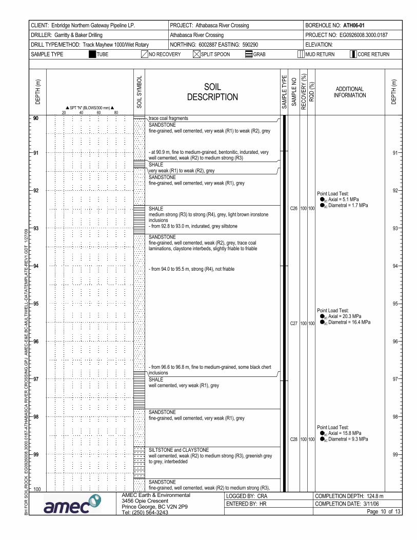
fine-grained, well cemented, weak (R2), grey, trace coallaminations, claystone interbeds, slightly friable to friable
fine-grained, well cemented, weak (R2) to medium strong (R3),
well cemented, weak (R2) to medium strong (R3), greenish greyto grey, interbedded
fine-grained, well cemented, very weak (R1), greySANDSTONE
well cemented, very weak (R1), greySHALE
- from 96.6 to 96.8 m, fine to medium-grained, some black chertinclusions
SANDSTONE
Point Load Test: UC Axial = 5.1 MPa UC Diametral = 1.7 MPa
90
SOILDESCRIPTION
Point Load Test: UC Axial = 20.3 MPa UC Diametral = 16.4 MPa
SANDSTONE
100
100
C26
Point Load Test: UC Axial = 15.8 MPa UC Diametral = 9.3 MPa
100
- from 94.0 to 95.5 m, strong (R4), not friable
100
C28
C27
100
- at 90.9 m, fine to medium-grained, bentonitic, indurated, verywell cemented, weak (R2) to medium strong (R3)
- from 92.8 to 93.0 m, indurated, grey siltstone
medium strong (R3) to strong (R4), grey, light brown ironstoneinclusions
SHALE
fine-grained, well cemented, very weak (R1), greySANDSTONE
SHALE
100
fine-grained, well cemented, very weak (R1) to weak (R2), greySANDSTONEtrace coal fragments
very weak (R1) to weak (R2), grey
NO RECOVERY
SAMP
LE N
O
CORE RETURN
100
SAMPLE TYPE
RECO
VERY
(%)
DEPT
H (m
)
SPT "N" (BLOWS/300 mm) 20 40 60 80
BH
FO
R S
OIL
/RO
CK
EG
0926
008.
3000
.018
7-A
THA
BA
SC
A R
IVE
R C
RO
SS
ING
.GP
J A
ME
C-E
&E
.BC
-MU
LTIW
ELL
-DA
TATE
MP
LATE
-RE
V1.
GD
T 1
/27/
09
RQD
(%)
BOREHOLE NO: ATH06-01PROJECT NO: EG0926008.3000.0187ELEVATION:
COMPLETION DEPTH: 124.8 mCOMPLETION DATE: 3/11/06
GRAB
91
92
93
94
95
96
97
98
99
SPLIT SPOON
SAMP
LE T
YPE
SOIL
SYMB
OL
AMEC Earth & Environmental3456 Opie CrescentPrince George, BC V2N 2P9Tel: (250) 564-3243 Page 10 of 13
LOGGED BY: CRAENTERED BY: HR
9090
91
92
93
94
95
96
97
98
99
PROJECT: Athabasca River CrossingAthabasca River CrossingNORTHING: 6002887 EASTING: 590290
DEPT
H (m
)
CLIENT: Enbridge Northern Gateway Pipeline LP.DRILLER: Garritty & Baker DrillingDRILL TYPE/METHOD: Track Mayhew 1000/Wet Rotary
91
92
93
94
95
96
97
98
99
MUD RETURNTUBE
ADDITIONALINFORMATION
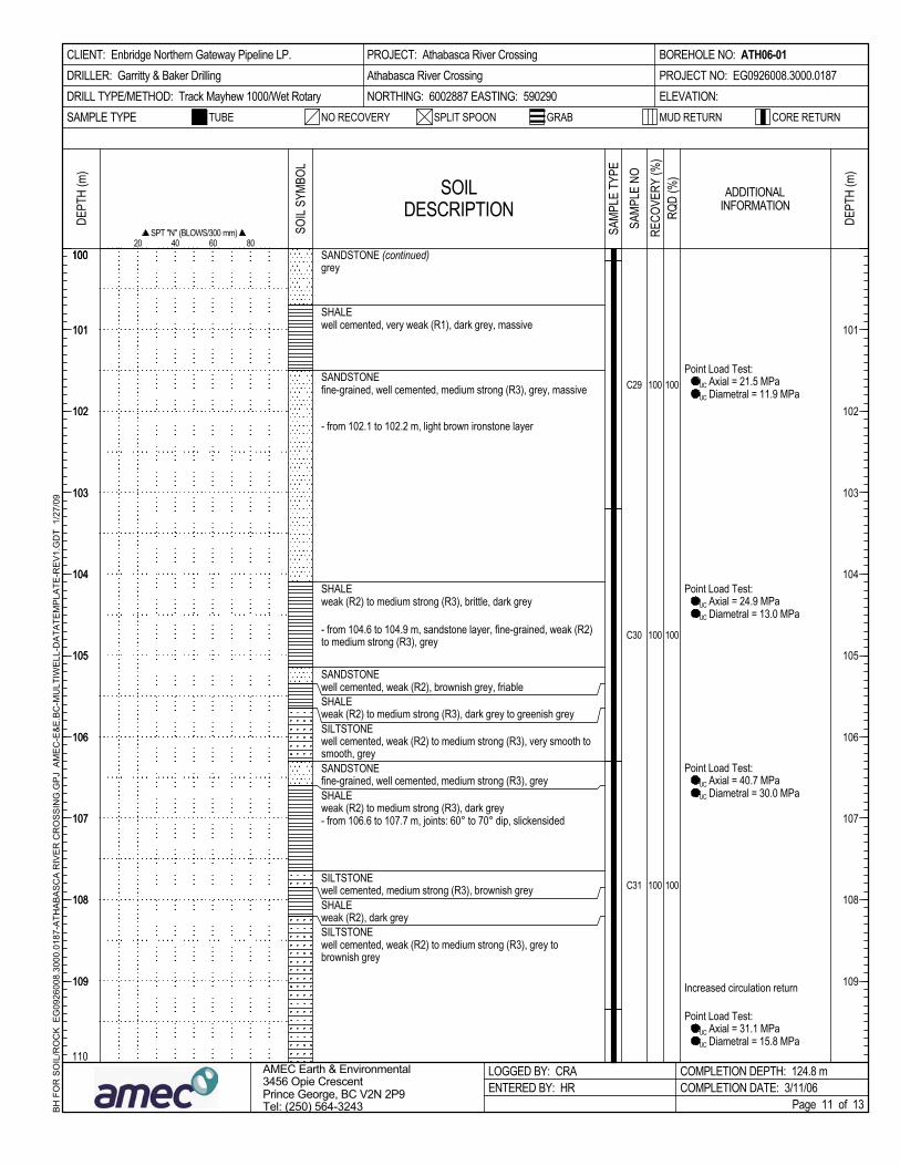
weak (R2) to medium strong (R3), dark grey
well cemented, weak (R2) to medium strong (R3), grey tobrownish grey
SILTSTONEweak (R2), dark greySHALEwell cemented, medium strong (R3), brownish grey
SHALE
- from 106.6 to 107.7 m, joints: 60° to 70° dip, slickensided
SHALEfine-grained, well cemented, medium strong (R3), greySANDSTONE
well cemented, weak (R2) to medium strong (R3), very smooth tosmooth, grey
SILTSTONE
SILTSTONE
Point Load Test: UC Axial = 31.1 MPa UC Diametral = 15.8 MPa
Increased circulation return
Point Load Test: UC Axial = 40.7 MPa UC Diametral = 30.0 MPa
Point Load Test: UC Axial = 24.9 MPa UC Diametral = 13.0 MPa
Point Load Test: UC Axial = 21.5 MPa UC Diametral = 11.9 MPa
100
100C29
well cemented, weak (R2), brownish grey, friable
100
100
weak (R2) to medium strong (R3), dark grey to greenish grey
100
C31
C30 100
SHALE
SANDSTONE
- from 104.6 to 104.9 m, sandstone layer, fine-grained, weak (R2)to medium strong (R3), grey
weak (R2) to medium strong (R3), brittle, dark greySHALE
- from 102.1 to 102.2 m, light brown ironstone layer
fine-grained, well cemented, medium strong (R3), grey, massive
well cemented, very weak (R1), dark grey, massive
greySANDSTONE (continued)
SANDSTONE
110
BH
FO
R S
OIL
/RO
CK
EG
0926
008.
3000
.018
7-A
THA
BA
SC
A R
IVE
R C
RO
SS
ING
.GP
J A
ME
C-E
&E
.BC
-MU
LTIW
ELL
-DA
TATE
MP
LATE
-RE
V1.
GD
T 1
/27/
09
20 40 60 80
DEPT
H (m
)
SPT "N" (BLOWS/300 mm)
CORE RETURN
100
RQD
(%)
SAMPLE TYPE
SOIL
SYMB
OL
LOGGED BY: CRAENTERED BY: HR
NO RECOVERY
COMPLETION DEPTH: 124.8 mCOMPLETION DATE: 3/11/06
GRAB
BOREHOLE NO: ATH06-01PROJECT NO: EG0926008.3000.0187ELEVATION:
SAMP
LE N
ORE
COVE
RY (%
)
DEPT
H (m
)
100
101
102
103
104
105
106
107
108
109
SPLIT SPOONTUBE
100
SOILDESCRIPTION
CLIENT: Enbridge Northern Gateway Pipeline LP.DRILLER: Garritty & Baker DrillingDRILL TYPE/METHOD: Track Mayhew 1000/Wet Rotary
101
102
103
104
105
106
107
108
109
Page 11 of 13
ADDITIONALINFORMATION
MUD RETURN
AMEC Earth & Environmental3456 Opie CrescentPrince George, BC V2N 2P9Tel: (250) 564-3243
PROJECT: Athabasca River CrossingAthabasca River CrossingNORTHING: 6002887 EASTING: 590290
SAMP
LE T
YPE
101
102
103
104
105
106
107
108
109

100
weak (R2), dark greenish grey- at 117.6 m, joint: 40° dip, slickensided
SILTSTONE and SANDSTONEfine-grained sandstone, well cemented, grey to brownish grey
SHALEvery weak (R1) to weak (R2), fractured, greenish grey to grey,interbedded with carbonaceous siltstone
- at 119.3 m, joint: 60° dip, slickensided
SPLIT SPOON
- below 116.2 m, weak (R2), grey to brownish grey
100
100
C32
Point Load Test: UC Axial = 20.3 MPa UC Diametral = 13.6 MPa
SOILDESCRIPTION
110
TUBE
C33
C34
100
100
100
SHALE
SHALE
Point Load Test: UC Axial = 7.3 MPa UC Diametral = 2.3 MPa- at 115.9 m, interbedded with claystone, light brown to rusty
brown, ironstone inclusions
- below 114.8 m, very weak (R1), massive, friable
- from 114.2 to 114.8 m, grey
fine-grained, well cemented, weak (R2) to medium strong (R3),brownish grey to grey
weak (R2) to medium strong (R3), dark grey
well cemented, medium strong (R3) to strong (R4), brownish greyto grey
SILTSTONE
greySHALE
- from 117.4 to 117.5 m, friable
SANDSTONE
SAMPLE TYPE
120
NO RECOVERY CORE RETURN
DEPT
H (m
)
DEPT
H (m
)
SAMP
LE N
O
Lost water, approximately300 L/m for 13 m of drilling
RECO
VERY
(%)
SPT "N" (BLOWS/300 mm) 20 40 60 80
BH
FO
R S
OIL
/RO
CK
EG
0926
008.
3000
.018
7-A
THA
BA
SC
A R
IVE
R C
RO
SS
ING
.GP
J A
ME
C-E
&E
.BC
-MU
LTIW
ELL
-DA
TATE
MP
LATE
-RE
V1.
GD
T 1
/27/
09
RQD
(%)
BOREHOLE NO: ATH06-01PROJECT NO: EG0926008.3000.0187ELEVATION:
GRAB
COMPLETION DEPTH: 124.8 mCOMPLETION DATE: 3/11/06
SAMP
LE T
YPE
111
112
113
114
115
116
117
118
119
CLIENT: Enbridge Northern Gateway Pipeline LP.DRILLER: Garritty & Baker DrillingDRILL TYPE/METHOD: Track Mayhew 1000/Wet Rotary
AMEC Earth & Environmental3456 Opie CrescentPrince George, BC V2N 2P9Tel: (250) 564-3243
SOIL
SYMB
OL
LOGGED BY: CRAENTERED BY: HR
110110
111
112
113
114
115
116
117
118
119
ADDITIONALINFORMATION
Page 12 of 13
111
112
113
114
115
116
117
118
119
MUD RETURN
PROJECT: Athabasca River CrossingAthabasca River CrossingNORTHING: 6002887 EASTING: 590290

CLIENT: Enbridge Northern Gateway Pipeline LP.DRILLER: Garritty & Baker DrillingDRILL TYPE/METHOD: Track Mayhew 1000/Wet Rotary
120
TUBE SPLIT SPOON
DEPT
H (m
)
121
122
123
124
125
126
127
128
129
C35
SAMP
LE T
YPE
AMEC Earth & Environmental3456 Opie CrescentPrince George, BC V2N 2P9Tel: (250) 564-3243
- below 121.2 m, weak (R2) to medium strong (R3), grey
C36
100
100
SHALE (continued)
SOILDESCRIPTION
fine-grained, well cemented, very weak (R1) to weak (R2),brownish grey
SHALEweak (R2), massive, dark grey to greenish grey
End of Hole at 124.8 mHole Grouted Upon Completion
100
100
Point Load Test: UC Axial = 17.5 MPa UC Diametral = 7.3 MPa
SANDSTONE
DEPT
H (m
)
SAMP
LE N
O
GRAB
BOREHOLE NO: ATH06-01PROJECT NO: EG0926008.3000.0187ELEVATION:
RQD
(%)
BH
FO
R S
OIL
/RO
CK
EG
0926
008.
3000
.018
7-A
THA
BA
SC
A R
IVE
R C
RO
SS
ING
.GP
J A
ME
C-E
&E
.BC
-MU
LTIW
ELL
-DA
TATE
MP
LATE
-RE
V1.
GD
T 1
/27/
09
20 40 60 80SPT "N" (BLOWS/300 mm)
COMPLETION DEPTH: 124.8 mCOMPLETION DATE: 3/11/06
120
Page 13 of 13
121
122
123
124
125
126
127
128
129
MUD RETURN CORE RETURN
121
122
123
124
125
126
127
128
129
ADDITIONALINFORMATION
120
LOGGED BY: CRAENTERED BY: HR
SOIL
SYMB
OL
RECO
VERY
(%)
SAMPLE TYPE
130
NO RECOVERY
PROJECT: Athabasca River CrossingAthabasca River CrossingNORTHING: 6002887 EASTING: 590290

TUBE
Lost circulation
Partial circulation
SOILDESCRIPTION
0
G1
CLAY, silty, sandy, some gravel, intermediate plasticity, firm tostiff, grain sizes up to 10 mm diameter, grey, moist, oxidized, tracecoal inclusions [TILL]
BH
FO
R S
OIL
/RO
CK
EG
0926
008.
3000
.018
7-A
THA
BA
SC
A R
IVE
R C
RO
SS
ING
.GP
J A
ME
C-E
&E
.BC
-MU
LTIW
ELL
-DA
TATE
MP
LATE
-RE
V1.
GD
T 1
/27/
09
DEPT
H (m
)
1
2
3
4
5
6
7
8
9
G2
G3
SAND, fine-grained, silty, uniformly graded, compact to dense,brown
SILT, trace fine-grained sand, soft, yellowish brown
G4
G5
G6
G7
CLAY, silty, intermediate plasticity, firm to stiff, brown, moist,oxidized, trace coal inclusions
SILT, trace fine-grained sand, low plasticity, soft to firm, grey[possible TILL]
SPLIT SPOONNO RECOVERY CORE RETURN
BOREHOLE NO: ATH06-02PROJECT NO: EG0926008.3000.0187ELEVATION:
DEPT
H (m
)
GRAB
10
SAMP
LE N
O
COMPLETION DEPTH: 70.1 mCOMPLETION DATE: 3/5/06
Page 1 of 8
SAMP
LE T
YPE
AMEC Earth & Environmental3456 Opie CrescentPrince George, BC V2N 2P9Tel: (250) 564-3243
CLIENT: Enbridge Northern Gateway Pipeline LP.DRILLER: Geotech Drilling Services Ltd.DRILL TYPE/METHOD: HP200/Odex
MUD RETURN
1
2
3
4
5
6
7
8
9
RQD
(%)
SAMPLE TYPE
PROJECT: Athabasca River CrossingAthabasca River CrossingNORTHING: EASTING:
1
2
3
4
5
6
7
8
9
00
LOGGED BY: BHENTERED BY: HR
SOIL
SYMB
OL
ADDITIONALINFORMATION
RECO
VERY
(%)

G8
Drill Pressure = 3.4 MPa
SOILDESCRIPTION
10
TUBE
DEPT
H (m
)
Drill Pressure = 3.6 MPa
BH
FO
R S
OIL
/RO
CK
EG
0926
008.
3000
.018
7-A
THA
BA
SC
A R
IVE
R C
RO
SS
ING
.GP
J A
ME
C-E
&E
.BC
-MU
LTIW
ELL
-DA
TATE
MP
LATE
-RE
V1.
GD
T 1
/27/
09
11
12
13
14
15
16
17
18
19
SPLIT SPOON
G9
G10
G11
G12
G13
Drill Pressure = 3.4 MPa
Drill Pressure = 3.6 MPa
CLAY, silty, sandy, some gravel, intermediate plasticity, firm tostiff, grain sizes up to 10 mm diameter, grey, moist, oxidized, tracecoal inclusions [TILL] (continued)
SHALEextremely weak (R0), dark brown
Casing installed to 13.1m
Drill Pressure = 3.3 MPa
NO RECOVERY
DEPT
H (m
)
SAMP
LE N
OSA
MPLE
TYP
E
RQD
(%)
GRAB
COMPLETION DEPTH: 70.1 mCOMPLETION DATE: 3/5/06
BOREHOLE NO: ATH06-02PROJECT NO: EG0926008.3000.0187ELEVATION:
AMEC Earth & Environmental3456 Opie CrescentPrince George, BC V2N 2P9Tel: (250) 564-3243
CLIENT: Enbridge Northern Gateway Pipeline LP.DRILLER: Geotech Drilling Services Ltd.DRILL TYPE/METHOD: HP200/Odex
MUD RETURN
11
12
13
14
15
16
17
18
19
CORE RETURN
Page 2 of 8
20
ADDITIONALINFORMATION
RECO
VERY
(%)
11
12
13
14
15
16
17
18
19
1010
LOGGED BY: BHENTERED BY: HR
SOIL
SYMB
OL
PROJECT: Athabasca River CrossingAthabasca River CrossingNORTHING: EASTING:
SAMPLE TYPE

20
Drill Pressure = 3.6 MPa
Drill Pressure = 3.6 MPa
Drill Pressure = 3.4 MPa
Drill Pressure = 3.6 MPa
Drill Pressure = 3.6 MPa
Lost circulation
Drill Pressure = 3.6 MPa
Drill Pressure = 3.6 MPa
SOILDESCRIPTION
G14
BH
FO
R S
OIL
/RO
CK
EG
0926
008.
3000
.018
7-A
THA
BA
SC
A R
IVE
R C
RO
SS
ING
.GP
J A
ME
C-E
&E
.BC
-MU
LTIW
ELL
-DA
TATE
MP
LATE
-RE
V1.
GD
T 1
/27/
09
TUBE SPLIT SPOON
DEPT
H (m
)
21
22
23
24
25
26
27
28
29
G15
G16
G17
G18
G19
G20
SHALE (continued)
SILTSTONEvery weak (R2), light grey
SHALEextremely weak (R0), dark brown
SILTSTONEvery weak (R1), dark brown to black
GRAB
30
NO RECOVERY CORE RETURN
DEPT
H (m
)
RQD
(%)
BOREHOLE NO: ATH06-02PROJECT NO: EG0926008.3000.0187ELEVATION:
SAMPLE TYPE
COMPLETION DEPTH: 70.1 mCOMPLETION DATE: 3/5/06
SAMP
LE N
OSA
MPLE
TYP
E
AMEC Earth & Environmental3456 Opie CrescentPrince George, BC V2N 2P9Tel: (250) 564-3243
CLIENT: Enbridge Northern Gateway Pipeline LP.DRILLER: Geotech Drilling Services Ltd.DRILL TYPE/METHOD: HP200/Odex
21
22
23
24
25
26
27
28
29
LOGGED BY: BHENTERED BY: HR
Page 3 of 8
ADDITIONALINFORMATION
PROJECT: Athabasca River CrossingAthabasca River CrossingNORTHING: EASTING:
21
22
23
24
25
26
27
28
29
2020
RECO
VERY
(%)
MUD RETURN
SOIL
SYMB
OL
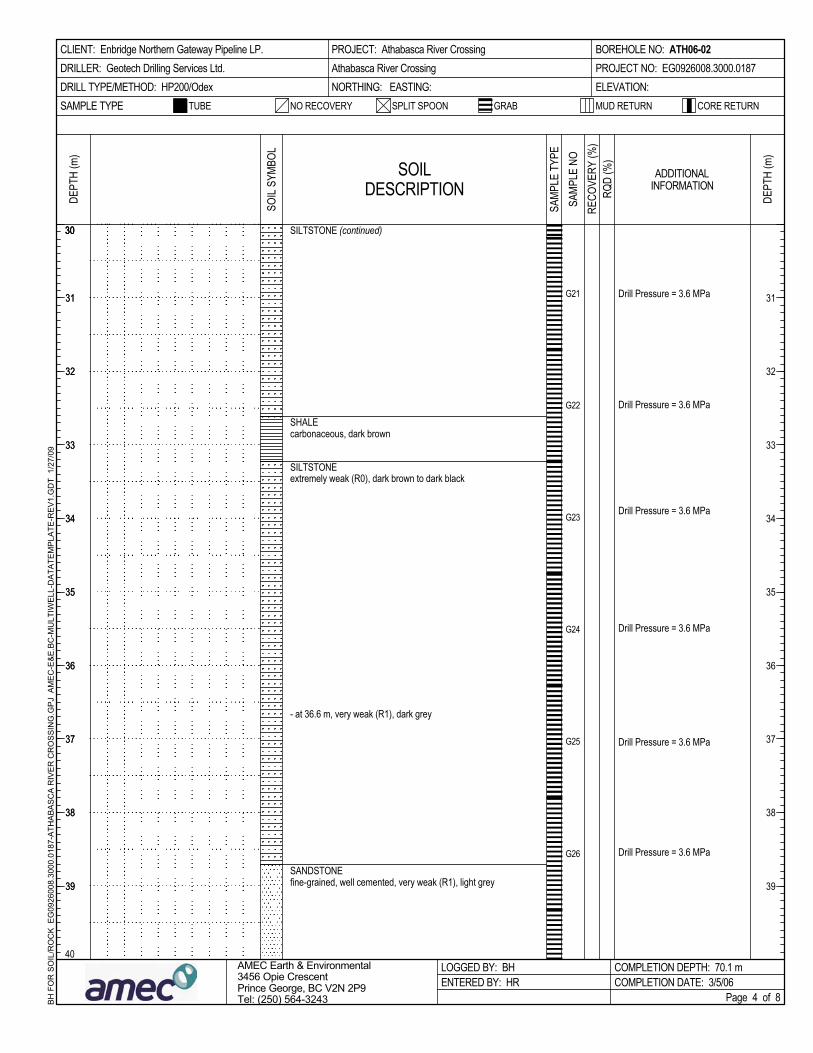
30
Drill Pressure = 3.6 MPa
Drill Pressure = 3.6 MPa
Drill Pressure = 3.6 MPa
Drill Pressure = 3.6 MPa
Drill Pressure = 3.6 MPa
Drill Pressure = 3.6 MPa
SOILDESCRIPTION
- at 36.6 m, very weak (R1), dark grey
BH
FO
R S
OIL
/RO
CK
EG
0926
008.
3000
.018
7-A
THA
BA
SC
A R
IVE
R C
RO
SS
ING
.GP
J A
ME
C-E
&E
.BC
-MU
LTIW
ELL
-DA
TATE
MP
LATE
-RE
V1.
GD
T 1
/27/
09
TUBE SPLIT SPOON
DEPT
H (m
)
31
32
33
34
35
36
37
38
39
G21
G22
G23
G24
G25
G26
fine-grained, well cemented, very weak (R1), light greySANDSTONE
SILTSTONE (continued)
SHALEcarbonaceous, dark brown
SILTSTONEextremely weak (R0), dark brown to dark black
SAMPLE TYPE NO RECOVERY CORE RETURN
DEPT
H (m
)
SAMP
LE N
O
GRAB
COMPLETION DEPTH: 70.1 mCOMPLETION DATE: 3/5/06
BOREHOLE NO: ATH06-02PROJECT NO: EG0926008.3000.0187ELEVATION:
SAMP
LE T
YPE
AMEC Earth & Environmental3456 Opie CrescentPrince George, BC V2N 2P9Tel: (250) 564-3243
CLIENT: Enbridge Northern Gateway Pipeline LP.DRILLER: Geotech Drilling Services Ltd.DRILL TYPE/METHOD: HP200/Odex
MUD RETURN
31
32
33
34
35
36
37
38
39
40
RQD
(%)
PROJECT: Athabasca River CrossingAthabasca River CrossingNORTHING: EASTING:
SOIL
SYMB
OL
LOGGED BY: BHENTERED BY: HR
30
31
32
33
34
35
36
37
38
39
RECO
VERY
(%)
ADDITIONALINFORMATION
Page 4 of 8
30

Drill Pressure = 3.6 MPa
Drill Pressure = 3.6 MPa
Water level at 36 m after leavingovernight
Drill Pressure = 3.6 MPa
Drill Pressure = 3.6 MPa
Drill Pressure = 3.6 MPa
SOILDESCRIPTION
Drill Pressure = 3.6 MPa
TUBE
BH
FO
R S
OIL
/RO
CK
EG
0926
008.
3000
.018
7-A
THA
BA
SC
A R
IVE
R C
RO
SS
ING
.GP
J A
ME
C-E
&E
.BC
-MU
LTIW
ELL
-DA
TATE
MP
LATE
-RE
V1.
GD
T 1
/27/
09
DEPT
H (m
)
41
42
43
44
45
46
47
48
49
40 G27
G28
G29
G30
G31
G32
G33
Drill Pressure = 3.6 MPa
SPLIT SPOON
SANDSTONE (continued)
SILTSTONEvery weak (R1), dark greyish and brown- at 42.7 m, grey
- from 44.8 to 45.7 m, very weak (R2), dark grey to brown
CORE RETURN
DEPT
H (m
)
SAMP
LE N
O
RQD
(%)
SAMPLE TYPE
BOREHOLE NO: ATH06-02PROJECT NO: EG0926008.3000.0187ELEVATION:
50
GRAB
COMPLETION DEPTH: 70.1 mCOMPLETION DATE: 3/5/06
ADDITIONALINFORMATION
CLIENT: Enbridge Northern Gateway Pipeline LP.DRILLER: Geotech Drilling Services Ltd.DRILL TYPE/METHOD: HP200/Odex
MUD RETURN
41
42
43
44
45
46
47
48
49
SAMP
LE T
YPE
NO RECOVERY
AMEC Earth & Environmental3456 Opie CrescentPrince George, BC V2N 2P9Tel: (250) 564-3243 Page 5 of 8
PROJECT: Athabasca River CrossingAthabasca River CrossingNORTHING: EASTING:
41
42
43
44
45
46
47
48
49
4040
LOGGED BY: BHENTERED BY: HR
SOIL
SYMB
OL
RECO
VERY
(%)

Drill Pressure = 3.6 MPa
Drill Pressure = 3.6 MPa
Drill Pressure = 3.6 MPa
Drill Pressure = 3.6 MPa
Drill Pressure = 3.6 MPa
SOILDESCRIPTION
50
Drill Pressure = 3.6 MPa
SPLIT SPOON
BH
FO
R S
OIL
/RO
CK
EG
0926
008.
3000
.018
7-A
THA
BA
SC
A R
IVE
R C
RO
SS
ING
.GP
J A
ME
C-E
&E
.BC
-MU
LTIW
ELL
-DA
TATE
MP
LATE
-RE
V1.
GD
T 1
/27/
09
51
52
53
54
55
56
57
58
59
G34
G35
G36
G37
G38
G39
G40
Drill Pressure = 3.6 MPa
DEPT
H (m
)
SANDSTONE (continued)fine-grained, well cemented, very weak (R1), light grey
SILTSTONEweak (R2), dark gray to black
SANDSTONEfine-grained, well cemented, very weak (R1), light grey
BOREHOLE NO: ATH06-02PROJECT NO: EG0926008.3000.0187ELEVATION:
SAMP
LE N
O
CORE RETURN
DEPT
H (m
)
TUBESAMPLE TYPE
60
GRAB
COMPLETION DEPTH: 70.1 mCOMPLETION DATE: 3/5/06
RQD
(%)
MUD RETURN
51
52
53
54
55
56
57
58
59
AMEC Earth & Environmental3456 Opie CrescentPrince George, BC V2N 2P9Tel: (250) 564-3243
NO RECOVERY
SAMP
LE T
YPE
CLIENT: Enbridge Northern Gateway Pipeline LP.DRILLER: Geotech Drilling Services Ltd.DRILL TYPE/METHOD: HP200/Odex
ADDITIONALINFORMATION
Page 6 of 8
PROJECT: Athabasca River CrossingAthabasca River CrossingNORTHING: EASTING:
51
52
53
54
55
56
57
58
59
5050
LOGGED BY: BHENTERED BY: HR
SOIL
SYMB
OL
RECO
VERY
(%)

Drill Pressure = 3.4 MPa
Drill Pressure = 3.4 MPa
Drill Pressure = 3.2 MPa
Drill Pressure = 3.4 MPa
Drill Pressure = 3.4 MPa
Drill Pressure = 3.4 MPa
SOILDESCRIPTION
TUBE
BH
FO
R S
OIL
/RO
CK
EG
0926
008.
3000
.018
7-A
THA
BA
SC
A R
IVE
R C
RO
SS
ING
.GP
J A
ME
C-E
&E
.BC
-MU
LTIW
ELL
-DA
TATE
MP
LATE
-RE
V1.
GD
T 1
/27/
09
DEPT
H (m
)
61
62
63
64
65
66
67
68
69
60
G41
G42
G43
G44
G45
G46
SPLIT SPOON
SANDSTONE (continued)
SILTSTONEmedium strong (R3), dark brown
SANDSTONEfine-grained, well cemented, very weak (R1), light grey
SILTSTONEweak (R2), light brown to green
BOREHOLE NO: ATH06-02PROJECT NO: EG0926008.3000.0187ELEVATION:
70
SAMP
LE N
O
NO RECOVERY
DEPT
H (m
)
SAMPLE TYPE GRAB
COMPLETION DEPTH: 70.1 mCOMPLETION DATE: 3/5/06
RQD
(%)
CLIENT: Enbridge Northern Gateway Pipeline LP.DRILLER: Geotech Drilling Services Ltd.DRILL TYPE/METHOD: HP200/Odex
MUD RETURN
AMEC Earth & Environmental3456 Opie CrescentPrince George, BC V2N 2P9Tel: (250) 564-3243
SAMP
LE T
YPE
61
62
63
64
65
66
67
68
69
CORE RETURN
ADDITIONALINFORMATION
PROJECT: Athabasca River CrossingAthabasca River CrossingNORTHING: EASTING:
61
62
63
64
65
66
67
68
69
6060
LOGGED BY: BHENTERED BY: HR
SOIL
SYMB
OL
RECO
VERY
(%)
Page 7 of 8
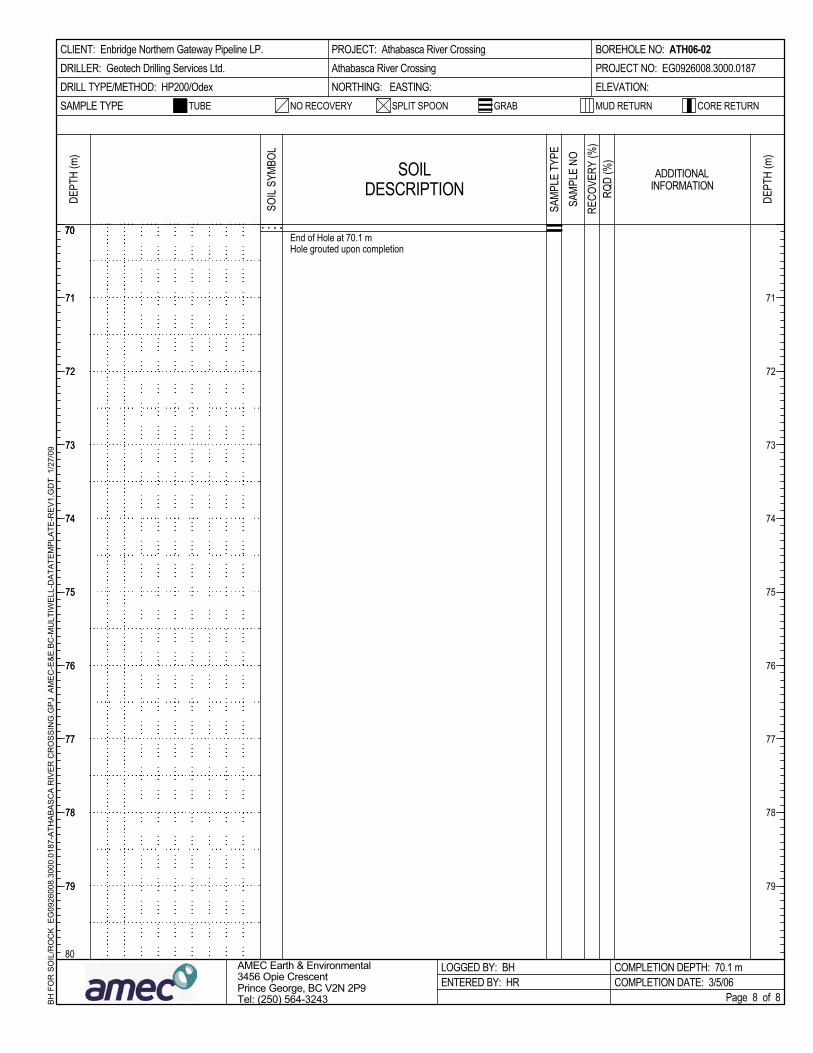
CLIENT: Enbridge Northern Gateway Pipeline LP.DRILLER: Geotech Drilling Services Ltd.DRILL TYPE/METHOD: HP200/Odex
71
72
73
74
75
76
77
78
79
AMEC Earth & Environmental3456 Opie CrescentPrince George, BC V2N 2P9Tel: (250) 564-3243
MUD RETURN
71
72
73
74
75
76
77
78
79
BH
FO
R S
OIL
/RO
CK
EG
0926
008.
3000
.018
7-A
THA
BA
SC
A R
IVE
R C
RO
SS
ING
.GP
J A
ME
C-E
&E
.BC
-MU
LTIW
ELL
-DA
TATE
MP
LATE
-RE
V1.
GD
T 1
/27/
09
SAMP
LE T
YPE
End of Hole at 70.1 mHole grouted upon completion
SOILDESCRIPTION
Page 8 of 8
TUBE SPLIT SPOON
DEPT
H (m
)
70
ADDITIONALINFORMATION
COMPLETION DEPTH: 70.1 mCOMPLETION DATE: 3/5/06
SAMP
LE N
O
GRAB
BOREHOLE NO: ATH06-02PROJECT NO: EG0926008.3000.0187ELEVATION:
RQD
(%)
PROJECT: Athabasca River CrossingAthabasca River CrossingNORTHING: EASTING:
71
72
73
74
75
76
77
78
79
7070
SOIL
SYMB
OL
RECO
VERY
(%)
SAMPLE TYPE
80
NO RECOVERY CORE RETURN
DEPT
H (m
)
LOGGED BY: BHENTERED BY: HR
