preparing secure vehicle-to-x communication systems
TRANSCRIPT

PREparing SEcuRe VEhicle-to-XCommunication Systems
Deliverable 2.4
System Integration Report
Project: PRESERVEProject Number: IST-269994Deliverable: D2.4Title: System Integration ReportVersion: 1.1Confidentiality: PublicEditor: Carsten Rolfes Part of the Seventh Framework ProgramCont. Authors: Carsten Rolfes, Norbert Bissmeyer,
Frank Kargl, Martin MoserFunded by the EC-DG INFSO
Date: 2015-08-20

D2.4 v1.1
Document History
Version Date Main author Summary of changesv0.1 2015-05-08 C. Rolfes (Fraunhofer
AISEC)Initial structure of document created
v0.2 2015-06-08 C. Rolfes (FraunhoferAISEC)
Regression update and photos
v0.3 2015-06-10 C. Rolfes (FraunhoferAISEC), Norbert Biss-meyer (Fraunhofer SIT)
Draft version for review
v0.4 2015-07-20 C. Rolfes (FraunhoferAISEC)
update
v1.0 2015-07-31 F. Kargl (UT) integrating comments and final revi-sion
v1.1 2015-08-20 C. Rolfes (FraunhoferAISEC), Martin Moser(Escrypt)
update of test result section withFOT PCB
ApprovalName Date
Prepared C. Rolfes 2015-07-20Reviewed All Project Partners 2015-07-25Authorized F. Kargl 2015-07-31
CirculationRecipient Date of submissionProject Partners 2015-08-20European Commission 2015-08-20
2015-08-20 IST-269994 i

Contents
Glossary iv
1 Introduction 11.1 Document Overview . . . . . . . . . . . . . . . . . . . . . . . . . . . . . . . 1
2 Verification and Test Environment 22.1 Strategy . . . . . . . . . . . . . . . . . . . . . . . . . . . . . . . . . . . . . . 2
2.1.1 RTL Simulation . . . . . . . . . . . . . . . . . . . . . . . . . . . . . . 52.1.2 FPGA Emulator . . . . . . . . . . . . . . . . . . . . . . . . . . . . . . 52.1.3 RTL-Simulation with ASIC netlist . . . . . . . . . . . . . . . . . . . . 62.1.4 ASIC . . . . . . . . . . . . . . . . . . . . . . . . . . . . . . . . . . . . 6
2.2 Environment . . . . . . . . . . . . . . . . . . . . . . . . . . . . . . . . . . . 62.2.1 Compiler . . . . . . . . . . . . . . . . . . . . . . . . . . . . . . . . . 6
3 Target of Evaluation 73.1 ASIC . . . . . . . . . . . . . . . . . . . . . . . . . . . . . . . . . . . . . . . . 7
3.1.1 Hardware . . . . . . . . . . . . . . . . . . . . . . . . . . . . . . . . . 73.1.2 Firmware . . . . . . . . . . . . . . . . . . . . . . . . . . . . . . . . . 7
3.2 Prototype Board . . . . . . . . . . . . . . . . . . . . . . . . . . . . . . . . . 83.3 FOT PCB . . . . . . . . . . . . . . . . . . . . . . . . . . . . . . . . . . . . . 93.4 Host Platform . . . . . . . . . . . . . . . . . . . . . . . . . . . . . . . . . . . 9
3.4.1 Hardware . . . . . . . . . . . . . . . . . . . . . . . . . . . . . . . . . 103.4.2 Software . . . . . . . . . . . . . . . . . . . . . . . . . . . . . . . . . 11
4 Verification and Test Results 134.1 ASIC functional tests . . . . . . . . . . . . . . . . . . . . . . . . . . . . . . . 134.2 PCB Interfaces . . . . . . . . . . . . . . . . . . . . . . . . . . . . . . . . . . 134.3 VSS Kit System . . . . . . . . . . . . . . . . . . . . . . . . . . . . . . . . . . 15
Bibliography 18
ii

List of Figures
3.1 PRESERVE HSM ASIC chip . . . . . . . . . . . . . . . . . . . . . . . . . 83.2 Chip die with logo . . . . . . . . . . . . . . . . . . . . . . . . . . . . . . . . 83.3 ASIC prototype board with opened chip mounting . . . . . . . . . . . . . . 93.4 PRESERVE FOT ASIC v2.0 board . . . . . . . . . . . . . . . . . . . . . . 103.5 VSS KIT 2 verification setup . . . . . . . . . . . . . . . . . . . . . . . . . . 11
iii

Glossary D2.4 v1.1
Glossary
Abbrev Synonyms Description Details
API Application ProgrammingInterface
An API is a particular set of spec-ifications that software programscan follow to communicate witheach other.
AU Application UnitHardware unit in an ITS stationrunning the ITS applications
ASN.1 Abstract Syntax NotationOne
ASN.1 is a standard and flexi-ble notation that describes datastructures for representing, en-coding, transmitting, and decod-ing data.
CA Certificate AuthorityA CA is an entity that issues digi-tal certificates.
CAM Cooperative AwarenessMessage
CAMs are sent by vehicles mul-tiple times a second (typicallyup to 10 Hz), they are broad-casted unencrypted over a single-hop and thus receivable by anyreceiver within range. They con-tain the vehicle’s current positionand speed, along with informa-tion such as steering wheel ori-entation, brake state, and vehiclelength and width.
CPU Central Processing Unit
2015-08-20 IST-269994 iv

Glossary D2.4 v1.1
Abbrev Synonyms Description Details
DENM DNMDecentralizedEnvironmentalNotification Message
A DENM transmission is trig-gered by a cooperative road haz-ard warning application, provid-ing information to other ITS sta-tions about a specific driving en-vironment event or traffic event.The ITS station that receives theDENM is able to provide appro-priate HMI information to the enduser, who makes use of these in-formation or takes actions in itsdriving and traveling.
ECC Elliptic CurveCryptography
ECC is an approach to public-keycryptography based on the alge-braic structure of elliptic curvesover finite fields.
ECMR ECU configurationmeasurement register
Register that contains the currentmeasurement value during run-time
ECR ECU configurationregister
Register used for secure bootand authenticated boot inside theHSM (similar to platform configu-ration register inside a TPM)
ECRR ECU configurationreference register
Register that contains the refer-ence value corresponding to theECMR
ECU Electronic Control UnitFOT Field Operational Test
FPGA Field programmable gatearray
HSM Hardware SecurityModule
HU Head-Unit
I2V I2C Infrastructure-to-VehicleCommunication between infras-tructure components like roadsideunits and vehicles
I2I Infrastructure-to-Infrastructure
Communication between multi-ple infrastructure components likeroadside units
IDM Identity & TrustManagement module
Module that handles the long-term certificate of the ITS station
2015-08-20 IST-269994 v

Glossary D2.4 v1.1
Abbrev Synonyms Description Details
ILP Inter Layer Proxy
Component introduced by theSeVeCom project, that capturesand allows modification of mes-sages between different layers ofa communication stack
IDK
ModuleAuthenti-cationKey
Device Identity Key
The Device Identity Key is intro-duced by EVITA and is used forHSM identification. The IDK canalso be certified by a manufac-turer authentication key.
ITS Intelligent TransportationSystems
Intelligent Transport Systems(ITS) are systems to supporttransportation of goods andhumans with information andcommunication technologies inorder to efficiently and safely usethe transport infrastructure andtransport means (cars, trains,planes, ships).
ITS-S ITS StationGeneric term for any ITS stationlike vehicle station, roadside unit,...
IDM ID & Trust ManagementModule
Module responsible for ID man-agement originating from SeVe-Com project.
LTC Long-Term Certificate
PRESERVE realization of anETSI Enrolment Credential. Thelong-term certificate authenti-cates a station within the PKI,e.g., for PC refill and may containidentification data and properties.
LTCA Long-Term CertificateAuthority
PRESERVE realization of anETSI Enrollment Credential Au-thority that is part of the PKI andresponsible for issuing long-termcertificates.
MAC Media Access Control
The MAC data communicationprotocol sub-layer is a sublayer ofthe Data Link Layer specified inthe seven-layer OSI model.
2015-08-20 IST-269994 vi

Glossary D2.4 v1.1
Abbrev Synonyms Description Details
OBD On-Board Diagnosis
OBD is a generic term referringto a vehicle’s self-diagnostic andreporting capability that can beused by a repair technician to ac-cess the vehicles sub-systems.
OEM Original EquipmentManufacturer
Refers to a generic car manufac-turer
OBU IVS On-Board Unit
An OBU is part of the V2X com-munication system at an ITS sta-tion. In different implementationsdifferent devices are used (e.g.CCU and AU)
PC Short TermCertificate
Pseudonym Certificate
A short term certificate authenti-cates stations in G5A communi-cation and contains data reducedto a minimum.
PCA Pseudonym CertificateAuthority
Certificate authority entity in thePKI that issues pseudonym cer-tificates
PIM Platform Integrity ModuleModule responsible for ensur-ing in-vehicle component integrityoriginating from EVITA project
PKI Public Key Infrastructure
A PKI is a set of hardware, soft-ware, policies, and proceduresneeded to create, manage, dis-tribute, use, store, and revoke dig-ital certificates.
TPM Trusted Platform Module
A TPM is both, the name of apublished specification detailing asecure crypto-processor that canstore cryptographic keys, as wellas the general name of imple-mentations of that specification,often called the "TPM chip" or"TPM Security Device".
UTC Coordinated UniversalTime
UTC is the primary time stan-dard by which the world regulatesclocks and time.
V2I C2I Vehicle-to-InfrastructureDirect vehicle to roadside infras-tructure communication using awireless local area network
V2V C2C Vehicle-to-VehicleDirect vehicle(s) to vehicle(s)communication using a wirelesslocal area network
2015-08-20 IST-269994 vii
Glossary D2.4 v1.1
Abbrev Synonyms Description Details
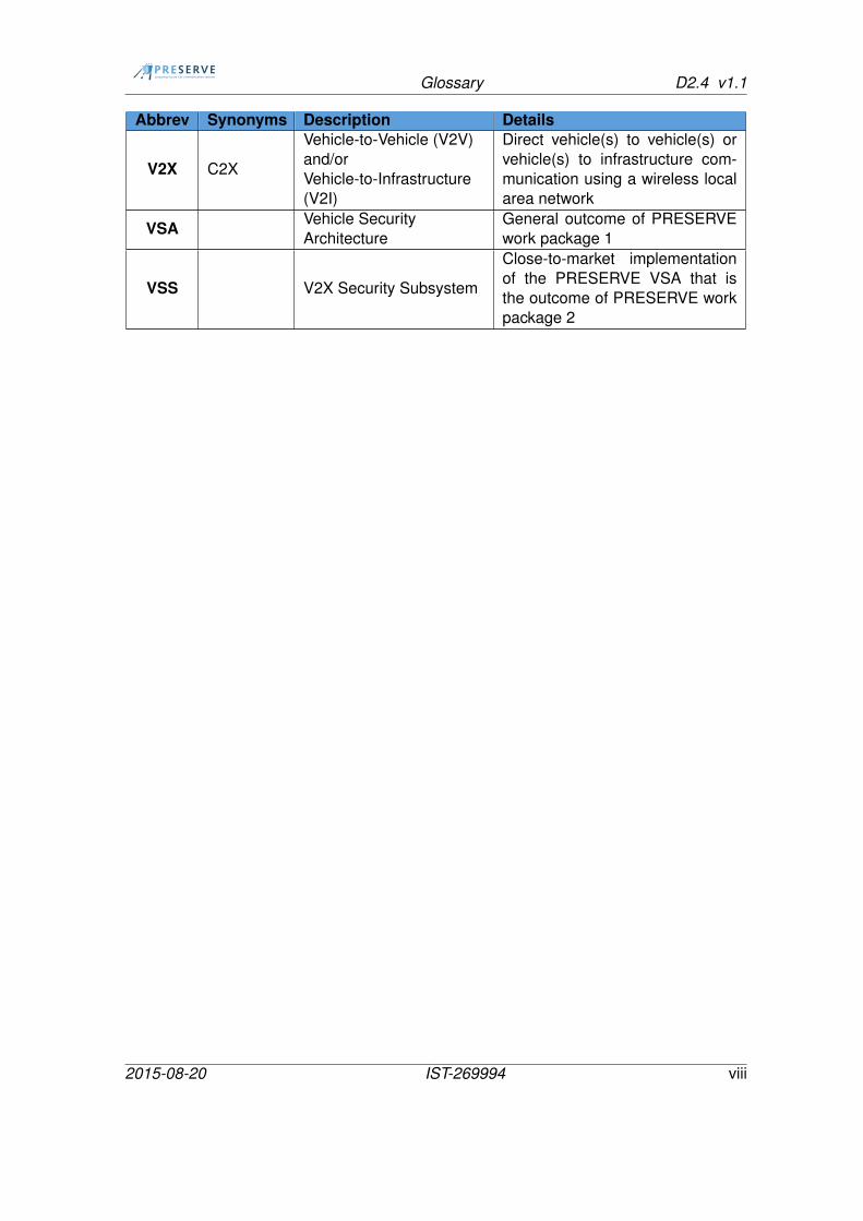
V2X C2X
Vehicle-to-Vehicle (V2V)and/orVehicle-to-Infrastructure(V2I)
Direct vehicle(s) to vehicle(s) orvehicle(s) to infrastructure com-munication using a wireless localarea network
VSA Vehicle SecurityArchitecture
General outcome of PRESERVEwork package 1
VSS V2X Security Subsystem
Close-to-market implementationof the PRESERVE VSA that isthe outcome of PRESERVE workpackage 2
2015-08-20 IST-269994 viii

1 Introduction D2.4 v1.1
1 Introduction
The PRESERVE Vehicle Security Subsystem (VSS), which is developed in the EU-researchproject PRESERVE (Preparing Secure Vehicle-to-X Communication Systems), has itsfocus on a secure communication between vehicles or infrastructure components (V2Xcommunication). V2X communication is used for example to send automatic position no-tifications, emergency warnings or traffic information that help the drivers reaching theirdestination safer and faster. Obviously, this goal cannot be reached without sophisticatedsecurity measures protecting integrity, authenticity, and privacy within the V2X communi-cation systems against malicious attacks.
This document reports on the integration of the different components of the VSS Kit 2including the ASIC-based Hardware Security Module (HSM) and the results of the vali-dation tests. It extends the VSS system design (Deliverable 2.2 [1]) and the ASIC-basedVSS prototype (Deliverable 2.3 [2]) described in earlier WP2 documents. While majorityof functional tests of the VSS Kit is already described in D2.3, this D2.4 focuses on thefunctional tests of the ASIC and its integration into the VSS Kit. More extensive testingis then conducted in tests in the testbed, which are described in Deliverable 3.2 and jointtests described in D3.3.
1.1 Document Overview
In Chapter 2 we give a short introduction to the architecture of the verification setup usedduring the development lifecycle of the ASIC. Directly thereafter, we give an overview ofthe different components of the VSS Kit 2 and their interfaces in Chapter 3. The documentconcludes with the test results of each component in Chapter 4. Furthermore, the prob-lems identified during the system integration with the prototype board are listed, whichresults in an improved design of the final ASIC board.
Please note that version 1.1. is an update of the report and includes the results of theASIC PCB version 2.
2015-08-20 IST-269994 1

2 Verification and Test Environment D2.4 v1.1
2 Verification and Test Environment
2.1 Strategy
The main objective of the tests strategy described in this deliverable is to write tests forthe top level verification of the SoC. This tests should be platform independent and can bereused for the four different devices under test (DUT) that have been created during thedevelopment cycle of the ASIC.
• RTL-Simulation
• FPGA Emulation
• RTL-Simulation with ASIC timing netlist (Place & Route)
• ASIC
• VSS Kit 2 (benchmark)
The top level verification does not replace the module verification. Module verification hasbeen conducted during module design and is described as part of D2.3. In fact, the toplevel verification relies on the assumption that all modules are verified in detail and workas expected. So, the purpose of the top level verification is to make some basic-level testsif the module is connected to the bus and responsive and to test more complex scenarios,like interaction with other modules.
The different tests are all written in C. The test suite consists of a lot of small tests, eachwith a different focus. Each test cases will always be run against defined testvector valuesand the result of the comparison between expected and obtained result will be reportedas passed or failed (with an error code). It is also necessary that all tests can be startedautomatically. This is called a regression test. The goal of this approach is to be able toverify changes in the design immediately. If there is a new version of the top level designa new regression run will be started and we will get as a result what problems are solvedand if new problems have arised, compared to the previous design.
The general approach of the ASIC functional test cases implementation is as follows:
• write the test in C (test.c)
• compile it (test.c -> test)
Simulation
– convert the test in a ramfile (test -> test.srec)
2015-08-20 IST-269994 2

2.1 Strategy D2.4 v1.1
– start the simulation testbench with the selected ramfile (test.srec)
– see the result (pass/failed) in the transcript
FPGA/ASIC
– load the binary with GRMON
– run the test
– see the result (pass/failed) at the UART interface
• collect the results and merge them to a report
Each test has a header which gives a short overview what steps will be carried out duringthis test case.
Listing 2.1: Header1 / / ∗∗∗∗∗∗∗∗∗∗∗∗∗∗∗∗∗∗∗∗∗∗∗∗∗∗∗∗∗∗∗∗∗∗∗∗∗∗∗∗∗∗∗∗∗∗∗∗∗∗∗2 / /3 / / Filename : reg_rw . c4 / / Version : 1.05 / / Created : 14.02.20126 / / Last Change : 14.02.20127 / / Author : Mar t in Baer8 / / Organ iza t ion : Fraunhofer AISEC − EMS9 / / Copyr ight ( c ) 2012 , Mar t in Baer
10 / /11 / /12 / / ∗∗∗∗∗∗∗∗∗∗∗∗∗∗∗∗∗∗∗∗∗∗∗∗∗∗∗∗∗∗∗∗∗∗∗∗∗∗∗∗∗∗∗∗∗∗∗∗∗∗∗13 / /14 / / STEP 0: I n i t i a l i z e15 / / STEP 1: Check rese tva lues16 / / STEP 2: Check implva lues17 / / STEP 3: Check the r e s u l t s18 / /19 / / ∗∗∗∗∗∗∗∗∗∗∗∗∗∗∗∗∗∗∗∗∗∗∗∗∗∗∗∗∗∗∗∗∗∗∗∗∗∗∗∗∗∗∗∗∗∗∗∗∗∗∗
We have to include some files to get the test working.
Listing 2.2: include files1 #include " r e g i s t e r . h "2 #include " g l o b a l _ fu n c t i on s . c "
For example, the registers of the SoC modules are defined in the register.h. This def-inition makes it easy for us to use the registers and port the test to different memorymappings.
2015-08-20 IST-269994 3
2.1 Strategy D2.4 v1.1
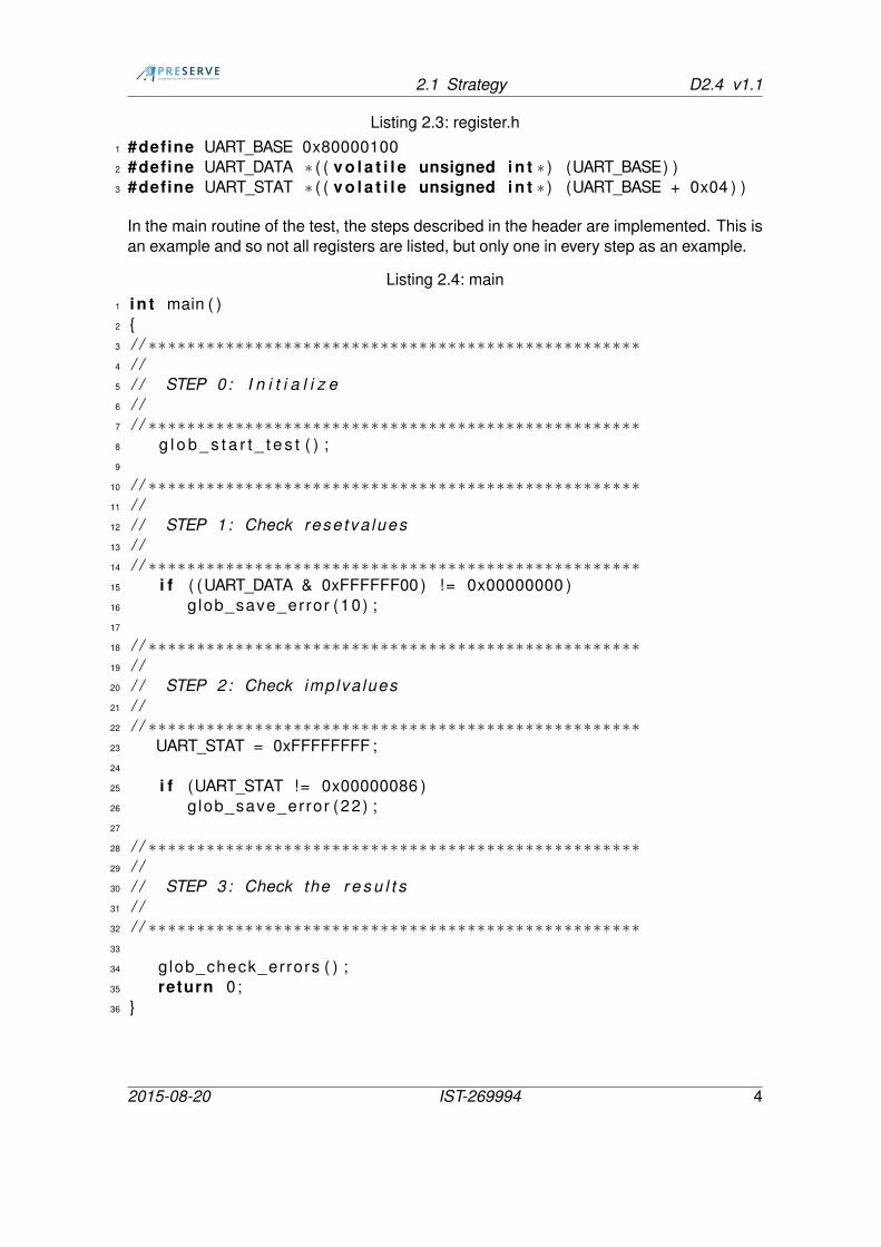
Listing 2.3: register.h1 #define UART_BASE 0x800001002 #define UART_DATA ∗ ( ( v o l a t i l e unsigned i n t ∗ ) (UART_BASE) )3 #define UART_STAT ∗ ( ( v o l a t i l e unsigned i n t ∗ ) (UART_BASE + 0x04 ) )
In the main routine of the test, the steps described in the header are implemented. This isan example and so not all registers are listed, but only one in every step as an example.
Listing 2.4: main1 i n t main ( )2 {3 / / ∗∗∗∗∗∗∗∗∗∗∗∗∗∗∗∗∗∗∗∗∗∗∗∗∗∗∗∗∗∗∗∗∗∗∗∗∗∗∗∗∗∗∗∗∗∗∗∗∗∗∗4 / /5 / / STEP 0: I n i t i a l i z e6 / /7 / / ∗∗∗∗∗∗∗∗∗∗∗∗∗∗∗∗∗∗∗∗∗∗∗∗∗∗∗∗∗∗∗∗∗∗∗∗∗∗∗∗∗∗∗∗∗∗∗∗∗∗∗8 g l o b _ s t a r t _ t e s t ( ) ;9
10 / / ∗∗∗∗∗∗∗∗∗∗∗∗∗∗∗∗∗∗∗∗∗∗∗∗∗∗∗∗∗∗∗∗∗∗∗∗∗∗∗∗∗∗∗∗∗∗∗∗∗∗∗11 / /12 / / STEP 1: Check rese tva lues13 / /14 / / ∗∗∗∗∗∗∗∗∗∗∗∗∗∗∗∗∗∗∗∗∗∗∗∗∗∗∗∗∗∗∗∗∗∗∗∗∗∗∗∗∗∗∗∗∗∗∗∗∗∗∗15 i f ( (UART_DATA & 0xFFFFFF00 ) != 0x00000000 )16 glob_save_error (10) ;17
18 / / ∗∗∗∗∗∗∗∗∗∗∗∗∗∗∗∗∗∗∗∗∗∗∗∗∗∗∗∗∗∗∗∗∗∗∗∗∗∗∗∗∗∗∗∗∗∗∗∗∗∗∗19 / /20 / / STEP 2: Check implva lues21 / /22 / / ∗∗∗∗∗∗∗∗∗∗∗∗∗∗∗∗∗∗∗∗∗∗∗∗∗∗∗∗∗∗∗∗∗∗∗∗∗∗∗∗∗∗∗∗∗∗∗∗∗∗∗23 UART_STAT = 0xFFFFFFFF ;24
25 i f (UART_STAT != 0x00000086 )26 glob_save_error (22) ;27
28 / / ∗∗∗∗∗∗∗∗∗∗∗∗∗∗∗∗∗∗∗∗∗∗∗∗∗∗∗∗∗∗∗∗∗∗∗∗∗∗∗∗∗∗∗∗∗∗∗∗∗∗∗29 / /30 / / STEP 3: Check the r e s u l t s31 / /32 / / ∗∗∗∗∗∗∗∗∗∗∗∗∗∗∗∗∗∗∗∗∗∗∗∗∗∗∗∗∗∗∗∗∗∗∗∗∗∗∗∗∗∗∗∗∗∗∗∗∗∗∗33
34 glob_check_errors ( ) ;35 return 0;36 }
2015-08-20 IST-269994 4

2.1 Strategy D2.4 v1.1
As you can see, in each step the result is checked against the expected values. If thecheck fails, an error code is saved. The function glob_check_errors is checking for errors,which arose during the execution of the test case. The result is then PASSED or FAILED.In the case of an error the error code is printed, too.
Although a top level verification is done, the tests were adopted to the different kind ofmodules. For every module we have the following test types:
• register read-write test - check if the module is connected.
• simple internal function tests - check if the module works as expected (only exem-plary, main work should be done in module verification)
• if necessary, tests where the module interact with other modules (e.g. interrupt istriggered)
• test including external communication
Every test case is located in a separate folder, together with the command files, Makefiles,etc. Also, in this folder is a README file located. In this file the test is described ina defined structure and a more detailed description can be found in the header of thesourcecode. Hence, it possible to iterate through all test folders, readout the READMEfiles and create a testplan with this information automatically.
2.1.1 RTL Simulation
A first run of these tests was conducted in the RTL simulation. For internal functionsof modules, this is straight-forward. Because we do not only want to run internal test, weexpanded this testbench with external I/O models where the external ports/pins of the chipare connected to the complements in the testbench. UART, SPI and I2C were tested withthe help of these models. Because the protocols of USB and Ethernet are more complexwe were not able to do a simulation of the full stack and utilized an FPGA emulator forthese tests.
2.1.2 FPGA Emulator
On the FPGA level the same tests are reused. Because there is no testbench around theFPGA we have to test the connections in a different way. Instead of a testbench we useda signal analyzer (like Bus Pirate) or directly connected the external interfaces to a hostPC. Of course, this part of the verification was automated as a regression, too.
2015-08-20 IST-269994 5

2.2 Environment D2.4 v1.1
2.1.3 RTL-Simulation with ASIC netlist
This is the same scenario as the first RTL-Simulation. In addition, timing information ofthe target technology and information of the backend design process are included, e.g.provided as an SDF file. Therefore, this kind of simulation takes much longer the theprevious pure top-level RTL simulation.
2.1.4 ASIC
We reused the emulator setup and replaced the FPGA with the ASIC prototype board forthese tests that were conducted after shipment of the ASIC.
2.2 Environment
2.2.1 Compiler
To compile the C-testfiles a sparc-elf-compiler is needed. In our setup we used the sparc-elf-3.4.4 from the Gaisler homepage: http://www.gaisler.com/index.php/downloads
We build the tests with the following compiler flags:
-Wall enable all warnings
-O0 disable optimization, because some parts of the test programs may make no sensefor the compiler and may be skipped therefore.
-I include some folders that are needed
We also have to create the srec file using the following command:
1 / usr / l o c a l / b in / sparc−e l f −objcopy −O srec t e s t t e s t . srec
2015-08-20 IST-269994 6

3 Target of Evaluation D2.4 v1.1
3 Target of Evaluation
This chapter describes the different system components tested in the verification. Thisincludes the ASIC, firmware, prototype board, Nexcom box, and VSS kit software. Thearchitecture, design, and implementation of the Vehicle Security Subsystem and its com-ponents are described in PRESERVE deliverables D1.2, D2.2 [1] and D2.3 [2] respec-tively.
3.1 ASIC
3.1.1 Hardware
The Hardware Security Module (HSM) is the main unit in charge of handling the secu-rity processing. It contains state-of-the-art crypto modules, which perform Elliptic CurveCryptography (ECC) and AES encryption, incorporates a True Random Number Genera-tor (TRNG) and a Physical Unclonable Function (PUF) module and is additionally able tocalculate SHA-2 256-bit HASH values according to the NIST standard. These crypto IPcores are connected via an AMBA bus system to a SPARC V8 processor (Gaissler Leon3) and are accessible via Ethernet, USB 2.0, SPI or I2C interfaces from the outside. Hencethis design is a System on Chip (SoC) solution for high security applications with moderncryptography inside, manufactured in a 55nm process from UMC.
A detailed description of the ASIC can be found in Deliverables D2.2 [2] and D2.3 [2]. 92packaged ASICs were available for testing. Figure 3.1 is showing photo of packaged chip.The PRESERVE logo is visible on the package and also the unpackaged chip die, seeFigure 3.2.
3.1.2 Firmware
For the system integration test an adapted ASIC firmware (see D2.3 [2]) was used. It isstored in the flash of the board and copied to the external flash memory during booting.The firmware has an Ethernet driver for communication and an ECC driver for signatureverification integrated. The tested firmware Version was asic_firmware v1.0.0
2015-08-20 IST-269994 7

3.2 Prototype Board D2.4 v1.1
Figure 3.1: PRESERVE HSM ASIC chip
Figure 3.2: Chip die with logo
3.2 Prototype Board
Figure 3.3 shows the prototype board manufactured to conduct the ASIC functional testsand external interface test. It has a socket to easily exchange the ASIC under test. Theschematics of the board are included in D2.3 [2]. The board has embedded an SRAM andflash chip for storing the firmware. Several interfaces (USB, Ethernet, Serial, JTAG), pushbuttons and LEDs can be used for interaction with the board and debugging.
2015-08-20 IST-269994 8

3.3 FOT PCB D2.4 v1.1
Figure 3.3: ASIC prototype board with opened chip mounting
3.3 FOT PCB
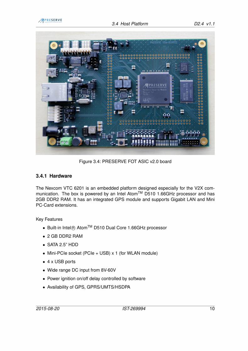
After successful functional verification of the ASIC and the prototype board 50 chips wereselected to be soldered on the final PCBs, which can then be used for future testing anddeployment. As you can see in Figure 3.4 the chips are mounted directly on the boardinstead of using the prototype socket. Apart from that, the external interfaces and thedimension are be the same as the prototype board.
As our testing revealed issues with the v1.0 boards and especially the external SRAM,which required the ASICs to be clocked at a lower rate, we also designed a revised ver-sion of the PCB (v2.0) with a different low-latency SRAM that allows us to run at fullfrequency.
3.4 Host Platform
The VSS Kit is optimized and extensively tested for the Nexcom Vehicle Telematics Com-puter and the Hitachi communication stack. This setup is used in many automotive re-search projects, which makes it the ideal platform for dissemination of the VSS Kit. Duringthe project the VSS Kit software was also successfully tested on different CPU and hostarchitectures like NEC Linkbird (Mips), Cohda Mk3 (ARM), Denso WSU (PowerPC). Fig-ure 3.5 shows the prototype board and the Nexcom box used for the system integrationtest together with some of the chip samples during regression tests.
2015-08-20 IST-269994 9
3.4 Host Platform D2.4 v1.1
Figure 3.4: PRESERVE FOT ASIC v2.0 board
3.4.1 Hardware
The Nexcom VTC 6201 is an embedded platform designed especially for the V2X com-munication. The box is powered by an Intel AtomTM D510 1.66GHz processor and has2GB DDR2 RAM. It has an integrated GPS module and supports Gigabit LAN and MiniPC-Card extensions.
Key Features
• Built-in Intel R© AtomTM D510 Dual Core 1.66GHz processor
• 2 GB DDR2 RAM
• SATA 2.5” HDD
• Mini-PCIe socket (PCIe + USB) x 1 (for WLAN module)
• 4 x USB ports
• Wide range DC input from 8V-60V
• Power ignition on/off delay controlled by software
• Availability of GPS, GPRS/UMTS/HSDPA
2015-08-20 IST-269994 10

3.4 Host Platform D2.4 v1.1
Figure 3.5: VSS KIT 2 verification setup
• Multiple display connections: Dual VGA and LVDS
• Support 2 x RS-232 (COM1,COM3), 1 x RS-232/RS-485 (COM2)
• 1 x GPIO 4IN, 4OUT
• Fanless design with ruggedized aluminum chassis
• 260mm (W) x 176mm (D) x 50mm (H)
Note that this is a platform that we expect to clearly exceed the capabilities of day 1on-board-units where cost-constraints will likely require less powerful CPUs, less RAM,etc..
3.4.2 Software
The Box is running a Linux operating system with the Hitachi communication stack. Adetailed description how to install and configure the VSS Kit V2 (ASIC and OpenSSLversion) can be found in Deliverable D4.3 [3] and in the PRESERVE Technical Report13 [5].
To switch between the SW-only and ASIC-based version of the VSS only the PCOM con-figuration file needs to be changed.
2015-08-20 IST-269994 11

3.4 Host Platform D2.4 v1.1
1 ########## ASIC r e l a t e d c o n f i g u r a t i o n \ \2 i t s . use . as ic = 1 \ \3 i t s . as ic . address = 192.168.0.108 \ \4 i t s . as ic . po r t = 7654 \ \
2015-08-20 IST-269994 12

4 Verification and Test Results D2.4 v1.1
4 Verification and Test Results
4.1 ASIC functional tests
The ASIC evaluation and the corresponding functional module tests as well as mitigationstrategies for the detected issues are described in detail in [2], Chapter 3.3. In summary,the issues do not have an impact or any drawbacks for the intended use-cases of thePRESERVE ASIC.
4.2 PCB Interfaces
The ASIC PCB has following external interfaces to communicate with the Host box.
• USB
• Ethernet
• I2C
• SPI
The USB and Ethernet are the main communications interfaces, whereas the slow backupinterfaces I2C and SPI can not use the full potential of the ASIC. As discovered during theASIC tests, the USB core is not fully functional. Therefore, the USB interface can not beused. The second high speed interface is working fine, so the PCB will be connected to thehost using the Ethernet interface. The I2C and SPI were tested successfully. The followinglisting is the output of a small test program to verify the Ethernet and ECC Signatureverification.
1 sudo . / esc_drv_ahb_eth_host − i 192.168.0.108 −v −r 1002
3 Using TCP/ IP connect ion4 2015−08−16 11:37:38 FUNCT: Enter
p reserveAs ic In i tConnec t ion ( )5 2015−08−16 11:37:38 DATA : 192.168.0.108 76546 2015−08−16 11:37:38 FUNCT: Leave
preserveAs ic In i tConnec t ion ( )7 Connecting to server @ 192.168.0.108:76548 Signature v e r i f i c a t i o n t e s t w i l l be performed .9 Test r e p e t i t i o n s 1
2015-08-20 IST-269994 13

4.2 PCB Interfaces D2.4 v1.1
10 2015−08−16 11:37:39 FUNCT: Enterp reseveAs icVer i f yS igna ture ( )
11 2015−08−16 11:37:39 FUNCT: Enter preserveAsicComm ( )12 2015−08−16 11:37:39 INFO : Data to send (138 bytes ) :13 2015−08−16 11:37:39 INFO :14 00 01 00 20 6C DC B1 3B 2B 8B DA 5D 68 B2 B8 1815 9C 26 B4 DB 66 A4 74 E1 CF 0C EF F9 DD AA 4C 0516 6D 94 5D C0 00 20 75 21 6F 0D 64 0D 90 19 CB 4117 45 9D AD F9 F0 FC 35 3B A6 85 F7 12 5A 73 39 0A18 D2 CF 91 E8 9A 50 00 20 CC A3 FE 20 ED 3E 3A 1819 86 A8 E7 6D 3A 7B 61 10 74 EA 4C E0 FC 35 A8 2B20 12 AC BD 9F 04 9D 7B B7 00 20 F9 FC 44 A8 22 6821 06 8B D1 D7 90 67 4A 80 D3 BF E6 80 57 A8 5B 2E22 73 80 44 AD C9 D3 F0 50 0C C223 2015−08−16 11:37:39 INFO : Data rece ived (36 bytes ) :24 2015−08−16 11:37:39 INFO :25 00 02 00 20 1F 0C 81 B5 C7 7F EF C0 55 9A A8 6626 60 76 4A CA DC C0 41 50 95 A9 21 83 83 C9 5F 6127 6F 56 85 CC28 2015−08−16 11:37:39 FUNCT: Leave preserveAsicComm ( )29 2015−08−16 11:37:39 FUNCT: Leave
preseveAs icVer i f yS igna ture ( )30 was number 031 −−−−−−−−−−−−−−−−−−−−−−−−−−−32 . . .33 2015−08−16 11:38:00 FUNCT: Enter
p reseveAs icVer i f yS igna ture ( )34 2015−08−16 11:38:00 FUNCT: Enter preserveAsicComm ( )35 2015−08−16 11:38:00 INFO : Data to send (138 bytes ) :36 2015−08−16 11:38:00 INFO :37 00 01 00 20 6C DC B1 3B 2B 8B DA 5D 68 B2 B8 1838 9C 26 B4 DB 66 A4 74 E1 CF 0C EF F9 DD AA 4C 0539 6D 94 5D C0 00 20 75 21 6F 0D 64 0D 90 19 CB 4140 45 9D AD F9 F0 FC 35 3B A6 85 F7 12 5A 73 39 0A41 D2 CF 91 E8 9A 50 00 20 CC A3 FE 20 ED 3E 3A 1842 86 A8 E7 6D 3A 7B 61 10 74 EA 4C E0 FC 35 A8 2B43 12 AC BD 9F 04 9D 7B B7 00 20 F9 FC 44 A8 22 6844 06 8B D1 D7 90 67 4A 80 D3 BF E6 80 57 A8 5B 2E45 73 80 44 AD C9 D3 F0 50 0C C246 2015−08−16 11:38:00 INFO : Data rece ived (36 bytes ) :47 2015−08−16 11:38:00 INFO :48 00 02 00 20 1F 0C 81 B5 C7 7F EF C0 55 9A A8 6649 60 76 4A CA DC C0 41 50 95 A9 21 83 83 C9 5F 6150 6F 56 85 CC51 2015−08−16 11:38:00 FUNCT: Leave preserveAsicComm ( )
2015-08-20 IST-269994 14

4.3 VSS Kit System D2.4 v1.1
52 2015−08−16 11:38:00 FUNCT: LeavepreseveAs icVer i f yS igna ture ( )
53 was number 9954 −−−−−−−−−−−−−−−−−−−−−−−−−−−55
56 Test passed
4.3 VSS Kit System
The system integration test of ASIC into the full VSS Kit was also successful. The VSSKit 2.20 setup on NEXCOM was already verified and tested before availability of the ASICHSM. The installation and setup of the Nexcom box, the integration of the VSS into theHitachi communication stack and the handling of the signature verification by the ASICwere carried out without issues. The internal testsuite of the VSS software as well as thecommunication with the PKI passed for the VSS Kit 2.
Below you find an snippet of the VSSKit logfile showing the successfull signature genera-tion and verification with the OpenSSL based version.
1 11:54:47.879221 CryptoModule : : SignMessage : e6d134d4b18815d62 11:54:47.885515 LowLevelOpenSSL : : Sign : Success3 11:54:47.885940 SecureCommunicationModule : : treatSendingPDU :4 0280bf800202015388dec640c6e19e0100520000043b9dc1e2e6a0ae6b1645 b29cc92a27433f5cb963746988900951983bc3693db7ea03c06e5427875886 c0a7f9fdf5b4f9148f4e8aebf9b753a72b9f1814b4765a3802e0210b240307 100002504010000000b0115043983154cbc0203000000affe3bd6446d8a858 36f77d3c31774a2376961ace56a388432063b8360f8f1e9277bbef5080db49 764a5a7607ac024e78be1a167986bf09aa5338aadf70704d7850000014deb
10 9ae231eb04038815d60524010b4c000019b9fa0a9684d9b443010000640f111 004c6e20e52c044ba125055e4fb28962f76a27e7c5a6f8c7a3663c6808eb012 50544ef9f127fd83011d35fddc2c33af83aca5d00e5d52084d6347173cf09913 11:54:47.886006 SecureCommunicationModule : : treatSendingPDU : end14 11:54:47.886040 SecureCommunicationModule : : treatReceivedPDU :
begin15 11:54:47.886271 SecureCommunicationModule : : treatReceivedPDU :16 0280bf800202015388dec640c6e19e0100520000043b9dc1e2e6a0ae6b16417 b29cc92a27433f5cb963746988900951983bc3693db7ea03c06e54278758818 c0a7f9fdf5b4f9148f4e8aebf9b753a72b9f1814b4765a3802e0210b2403019 100002504010000000b0115043983154cbc0203000000affe3bd6446d8a8520 36f77d3c31774a2376961ace56a388432063b8360f8f1e9277bbef5080db421 764a5a7607ac024e78be1a167986bf09aa5338aadf70704d7850000014deb22 9ae231eb04038815d60524010b4c000019b9fa0a9684d9b443010000640f123 004c6e20e52c044ba125055e4fb28962f76a27e7c5a6f8c7a3663c6808eb024 50544ef9f127fd83011d35fddc2c33af83aca5d00e5d52084d6347173cf099
2015-08-20 IST-269994 15

4.3 VSS Kit System D2.4 v1.1
25 11:54:47.886816 IncomingMessageManager : : CheckCamSecuri tyProf i le :Success
26 11:54:47.898000 LowLevelOpenSSL : : V e r i f y : Success27 11:54:47.898301 PCOMCryptoModule : : V e r i f y c e r t i f i c a t e : Success28 11:54:47.905366 LowLevelOpenSSL : : V e r i f y : Success29 11:54:47.905542 PCOMCryptoModule : : V e r i f y c e r t i f i c a t e : Success30 11:54:47.905591 Cer t i f i ca teManager : : A d d C e r t i f i c a t e :
e6d134d4b18815d631 11:54:47.913636 LowLevelOpenSSL : : V e r i f y : Success32 11:54:47.913835 PCOMCryptoModule : : V e r i f y : Success33 11:54:47.914006 SecureCommunicationModule : : treatReceivedPDU : end34 11:54:47.914209 SecureCommunicationModule : : treatSendingPDU :
begin35 11:54:47.914270 OutgoingMessageManager : : OutgoingMessageManager :
a id o f sender = 2436 11:54:47.914712 OutgoingMessageManager : :
CreateSigner In foForCamProf i le : d iges t w i l l be used37 11:54:47.914758 CryptoModule : : SignMessage : e6d134d4b18815d638 11:54:47.920877 LowLevelOpenSSL : : Sign : Success
Now the test is repeated with with the ASIC based version.
1 12:09:33.814176 LowLevelOpenSSLWithASIC : : LowLeve l In i t :p reserveAs ic In i tConnec t ion success
2 12:09:33.819952 SecureCommunicationModule : : treatSendingPDU :begin
3 12:09:33.820075 OutgoingMessageManager : : OutgoingMessageManager :a id o f sender = 24
4 12:09:33.820640 OutgoingMessageManager : :CreateSigner In foForCamProf i le : d iges t w i l l be used
5 12:09:33.820734 CryptoModule : : SignMessage : e6d134d4b18815d66 12:09:33.837269 LowLevelOpenSSL : : Sign : Success7 12:09:33.837481 SecureCommunicationModule : : treatSendingPDU :8 02158001e6d134d4b18815d60000014debcfb097060524010a4c000019b99 fa0a9684d9430100002ac1efb54696c4baa2f4a80db151c9eaa533e722de
10 fe639686c081210762ea8fc4fbe8ca55b2d30de601d691423639711926ed11 40a21906b62b29363df9c169cd12 12:09:33.837543 SecureCommunicationModule : : treatSendingPDU : end13 12:09:33.837583 SecureCommunicationModule : : treatReceivedPDU :
begin14 12:09:33.837683 SecureCommunicationModule : : treatReceivedPDU :15 02158001e6d134d4b18815d60000014debcfb097060524010a4c000019b916 fa0a9684d9430100002ac1efb54696c4baa2f4a80db151c9eaa533e722de17 fe639686c081210762ea8fc4fbe8ca55b2d30de601d691423639711926ed18 40a21906b62b29363df9c169cd
2015-08-20 IST-269994 16

4.3 VSS Kit System D2.4 v1.1
19 12:09:33.837912 IncomingMessageManager : : CheckCamSecuri tyProf i le :Success
20 12:09:33.837996 PCOMCryptoModule : : V e r i f y : PCOMCryptoModule : :V e r i f y : c e r t i f i c a t e \%s al ready v e r i f i e d ( e6d134d4b18815d6 )
21 12:09:33.843893 LowLevelOpenSSLWithASIC : : V e r i f y : Success22 12:09:33.844165 PCOMCryptoModule : : V e r i f y : Success23 12:09:33.844240 SecureCommunicationModule : : treatReceivedPDU : end
Further tests were conducted as part of the internal FOT 2. A detailed analysis of the VSSKit including benchmarks and attacker scenarios is published in PRESERVE D3.2: FOTTrial 2 Results [4] where also overall performance benchmarks are included.
2015-08-20 IST-269994 17

Bibliography D2.4 v1.1
Bibliography
[1] F. Bache, M. Bär, R. Hesselbarth, S. Joost, M. Moser, C. Rolfes, C. Schlipp, andF. Smailbegovic, “PRESERVE D2.2 ASIC Design Specification,” PRESERVE consor-tium, Deliverable, January 2015.
[2] N. Bißmeyer, D. Estor, M. Feiri, S. Joost, F. Kargl, M. Lange, S. Mauthofer, R. Moalla,M. Moser, J. Petit, M. Sall, and F. Smailbegovic, “PRESERVE D2.3 ASIC-based VSSPrototype,” PRESERVE consortium, Deliverable, August 2015.
[3] C. Jouvray and M. Sall, “PRESERVE D 4.3 - VSS Distribution Kit V2,” PRESERVEconsortium, Deliverable, June 2015.
[4] C. Rolfes, M. Feiri, F. Kargl, A. Giannetsos, S. Gisdakis, and M. Sall, “PRESERVED3.2: FOT Trial 2 Results,” PRESERVE consortium, Deliverable, July 2015.
[5] M. Sall, “PRESERVE Technical Report 13 - Use of the Nexcom Tar File,” PRESERVEconsortium, Technical Report 0.1, April 2015.
2015-08-20 IST-269994 18