presentation - load dump analysis
TRANSCRIPT

Load Dump Analysis
Ansoft CorporationPittsburgh, PA

2-3 kW power generation capability
Engine
12VBattery
Loads
14V
Starter
OPENs occur here….
…or here.
WHY?• Cables corrode and
break• Nuts & bolts come
loose• Mechanics disconnect
the wrong wire at the wrong time.
14 V Single Battery System
Alternator
…or here…

InstancesA major OEM received six new
42 volt alternators from a supplier. Three were destroyed in testing during the first month. That’s $15,000 up in smoke. They bought SIMPLORER.
Another major OEM worked for over a year to create an accurate Saber alternator model that could be fit to parametric data. They have not succeeded. Ansoft and the OEM are discussing the deployment of SIMPLORER.

Why should you be interested?Solving “by hand”
Time consumingError prone
TestingDestroy or degrade partsVery difficult to repeatInsufficient quantity of parts available
SimulationParts are virtual…don’t “smoke”Exactly repeatable
All are necessary to some extent and support one another.
Options are few!

Ansoft’s Solution
RMxprtMotor/generator design tool that can automatically produce a model for SIMPLORER
SIMPLORERsimulate the alternator, the battery, the loads and the devices and strategies that control and regulate the alternator

Design Flow
Maxwell2DMaxwell3D
Static, Harmonic, Transient
Maxwell Equivalent Circuit Generator
Geometry & Material
Parametric Solution
Parameter Sets, Lookup
Tables, Models
Model G
eneration
Model Generation
Model Order Reduction
Mod
el
Gen
erat
ion
Parameters &
Models
Optimization
Optimization
Optimization
RMxprt

Multi Domain SimulationSIMPLORER Simulation Data Bus
Simulator Coupling Technology
CircuitSimulator
Block DiagramSimulator
State MachineSimulator
Simulink
MathCad
Maxwell2D/3DElectromagnetismElectro mechanics
C/C++ Interface
Model DatabaseElectrical, Blocks, States, Machines, Automotive, Hydraulic,
Mechanics, Power, Semiconductors…
VHDL-AMSSimulator

Specifications
RMxprt
ModelFEA
SimplorerECE
RMxprt Data Input

RMxprt - LINK RMxprt - LINK
A
B
C
Torque
Position
RMxprtLink1
E1
E2
A+ Torque
J
MchRMas1
STF
MchRStf1
J
MchRMas2
STF
MchRStf2
J
MchRMas3
+ V
Speed
+ V
Position
RMxprt -> SIMPLORER
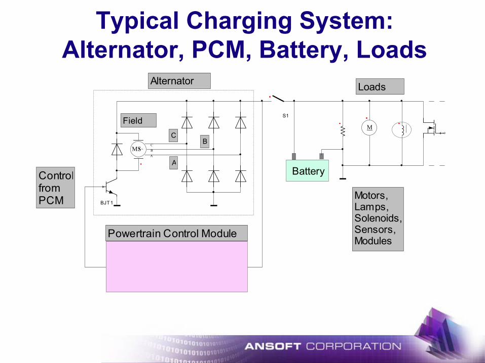
BJT1
S1
Alternator
A
BC
Field
ControlfromPCM
Powertrain Control Module
3 ~MS BA
C
Battery
M
Loads
Motors,Lamps,Solenoids,Sensors,Modules
Typical Charging System: Alternator, PCM, Battery, Loads

Charging System in SIMPLORER
RLOADS
Alternator
A
B
C
FieldIGBT1
+ V
Position
Speed
RCable
D2 D3 D4
D5D6D7
R1
C_Bat
R_Dis
D8
D9
S1
Y t
CS
R_wire11
L_wire13000 RPM
A +
AM1
A+
AM2
MEAN VALUEMEAN_I_Field
MEAN VALUE
MEAN_I_Load
+ V VM1
MEAN VALUE
MEAN_Vout
SUM1.VAL > 0
42
A
B
C
Torque
Position
Field
RMxprtLink1
SET: ctrl_1:=0SET: ctrl_1:=1
D1
OPEN at 350msec
ctrl_1
AbsSUM1
FCT_ABS1
SAWTOOTHV
SUM1.VAL <= 0COMP1
S & H

Output Voltage, Average Output(X10), and Control Signal(X100)
Simulation Results
(Scaled at 100*Control Signal and 10*Average Output)
MEAN_Vout.VALVM1.Vctrl_1
t
597.38
-100.00
0
100.00
200.00
300.00
400.00
500.00
0 1.000.25 0.50 0.75

Field Current
Simulation ResultsR_WandB.I
t
20.00
-2.00
0
2.50
5.00
7.50
10.00
12.50
15.00
17.50
0 1.000.20 0.40 0.60 0.80
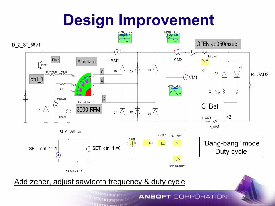
Add zener, adjust sawtooth frequency & duty cycle
RLOADS
Alternator
A
B
C
FieldIGBT1
+ V
Position
Speed
RCable
R_WandB D2 D3 D4
D5D6D7
R1
C_Bat
R_Dis
D8
D9
S1
Y t
CS
R_wire11
L_wire1
L_wirec
3000 RPM
A+
AM1A
+
AM2
MEAN VALUEMEAN_I_Field
MEAN VALUEMEAN_I_Load
+ V VM1
MEAN VALUEMEAN_Vout
SUM1.VAL > 0
42
A
B
C
Torque
Position
Field
RMxprtLink1
SET: ctrl_1:=0SET: ctrl_1:=1
D1
OPEN at 350msec
ctrl_1
AbsSUM1
FCT_ABS1
SAWTOOTHV
SUM1.VAL <= 0COMP1
S & H
D_Z_ST_56V1
“Bang-bang” modeDuty cycle
Design Improvement

20Hz Sampling with 90/10 PWM
Output Voltage
Average Output Voltage
Field Current
VM1.V
t
60.00
-10.000
10.00
20.00
30.00
40.00
50.00
0 5.001.00 2.00 3.00 4.00
MEAN_Vout.VAL
t
50.00
-5.000
10.00
20.00
30.00
40.00
0 5.001.00 2.00 3.00 4.00
R_WandB.I
t
12.00
0
2.00
4.00
6.00
8.00
10.00
0 5.001.00 2.00 3.00 4.00

VM1.V
t
60.00
-10.000
10.00
20.00
30.00
40.00
50.00
0 2.000.50 1.00 1.50
MEAN_Vout.VAL
t
50.00
-5.000
10.00
20.00
30.00
40.00
0 2.000.50 1.00 1.50
R_WandB.I
t
12.00
0
2.00
4.00
6.00
8.00
10.00
0 2.000.50 1.00 1.50
16Hz Sampling with 90/10 PWM
Output Voltage
Average Output Voltage
Field Current

RMxprt and SIMPLORER enable the engineer to study all thedesign alternatives quickly and without destroying or degrading the properties of valuable components. With thisinformation highly focused testing can be carried out to complete the development process.
Benefits:
Shortened development timeImproved performance and reliabilityGreater customer satisfactionLower warranty costs
Summary