presented by: chilled water and david coe, m.airah
TRANSCRIPT

Welcome to AIRAH’s WA Division Event
Presented by:
David Coe, M.AIRAH, Regional Contracts
and Engineering Manager (WA),
Envar Engineers and Contractors
and
Lindsay Turner, Affil.AIRAH,
Managing Director, Airskill
Chilled Water and
Cooling Tower
Design
Thank you to our Sponsor


Wednesday, November 18 • 4 - 7pm
AIRAH Perth Industry Night
HBF Stadium
airah.org.au/calendarUpcoming AIRAH WA Events
Wednesday, October 21 • 12 - 3pm
AIRAH WA Members’ Centenary Lunch
Ascot Racecourse, Ascot

Join AIRAH
airah.org.au/join

AIRAH is celebrating its Centenary
Leading HVAC&R for 100 years
G E T I N V O L V E D + F I N D O U T M O R E A T A I R A H 1 0 0 . O R G . A U
Share photos
and memories
Attend our
Centenary
events
Explore the
“100 Faces”
of AIRAH
See the
timeline, from
1920 to today
Join us at
Outlook 2020

w w w . a r m f w a . o r g . a u
Presenting:
Kim Cramer, M.AIRAH, Trustee and Past Chairman of The Alan Robert Memorial Fund Board and Director, Reliable Energy Solutions
The Alan Robert Memorial Fund proudly offers financial support
for training in Air Conditioning and Refrigeration.
For more information or to apply, visit:

Presenting:
David Coe, M.AIRAH, Regional Contracts
and Engineering Manager (WA),
Envar Engineers and Contractors
and
Lindsay Turner, Affil.AIRAH,
Managing Director, Airskill

CHILLED WATER SYSTEM PRESENTATION

HVAC design is not black and white.
There are numerous methodology's and ideologies that can achieve the same result.
Good design is based around determining and implementing an efficient, cost effective and robust system to service the application. Good design goes hand in hand with best installation practices.
This presentation will focus on understanding the suitability of plant and equipment and installation best practice for HVAC Chilled water systems. It will reference commonly used systems employed to service office
and commercial applications.
Many of the principles employed in this presentation can be applied in other areas of HVAC applications.
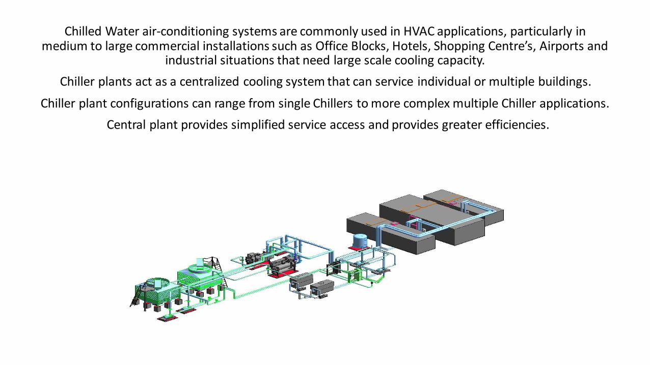
Chilled Water air-conditioning systems are commonly used in HVAC applications, particularly in medium to large commercial installations such as Office Blocks, Hotels, Shopping Centre’s, Airports and
industrial situations that need large scale cooling capacity.
Chiller plants act as a centralized cooling system that can service individual or multiple buildings.
Chiller plant configurations can range from single Chillers to more complex multiple Chiller applications.
Central plant provides simplified service access and provides greater efficiencies.

Chilled Water systems provide cooling to an application by using chilled water to absorb heat.
Chilled water systems are a closed loop system, the chilled water circuit consists of a series of pipes, pumps,valves and fittings that form a loop.
Chillers provide chilled water that is pumped to various heat exchange systems such as Air Handling, Fan Coilunits, process plant and equipment. Chilled water passes though heat exchange equipment where it absorbsheat and returns to the Chillers, the Chiller then removes heat from the water by means of a refrigeration cycleand returns the chilled water to the loop to repeat the process.

The refrigeration circuit is made up of four main components:
1 The compressor
2 The evaporator
3 Thermal expansion valve (TX valve)
4 The condenser
The compressor takes refrigerant and compresses the refrigerant to high pressure high temperature gas. Therefrigerant travels to the condenser (which can be air or water cooled) where the heat is rejected and the gascondenses to a liquid. The refrigerant then passes through a thermal expansion valve (TX valve), which metersthe amount of refrigerant passing into the evaporator. The TX valve takes the high pressure liquid and changesit to a low pressure, cold saturated gas. This saturated gas enters the evaporator and the gas then changesstate to a dry gas (no liquid present) within the evaporator. As a process of changing of state, heat is absorbedwithin the evaporator from the fluid circuit thus cooling the water. The cool dry gas re-enters the compressorwhere the cycle is then repeated.

Compressors:
Compressors used in chilled water plant are generally of four types:
1 Centrifugal
2 Screw
3 Scroll
4 Reciprocating

Centrifugal Compressors:
The centrifugal type compressor is quite easy to spot as the compressor is above the Chiller with a large voluteshaped pipe curling around into the condenser. Centrifugal compressors are the most common compressorsused in large chilled water system applications.
The refrigerant flows in through the suction line, hits into the centre of the impeller where it will be directed bythe blades. The blades rotate and that imparts an angular velocity onto the particles of the refrigerant. Thisangular velocity makes the refrigerant particles fly out at high velocity, in all directions, and collects in thevolute (the outer curl) where it increases in pressure from the kinetic energy, it then passes down into thecondenser.

Turbocor Compressor:
A variation of the centrifugal type is the Turbocor compressor. Turbocor compressors are much smaller unitsmounted also to the top of the Chillers. These work very similar to the centrifugal type, but they have twostage compressors inside. The refrigerant flows in through the front, passes through the two differentcompressors and then the refrigerant exits and travels down into the condenser. These usually have magneticbearings and electronic motors inside, which make these units very efficient. Turbocor are becoming muchmore common and they are set to continue this trend.

Screw Compressors:
Screw compressors are used in both water cooled and air cooled Chillers. With the water cooled type, thecompressor is on top of the chiller and with the air cooled type, the compressors is under the Chiller.
Inside the compressor are two interconnecting screws. The refrigerant will enter into a void between the twoscrews, as the screws rotates they push the refrigerant further into the compressor and squeeze it into a smallspace. The refrigerant exits at high pressure high temperature.

Reciprocating Compressors:
Reciprocating type compressors are becoming less common because newer, more efficient, technology hasbeen replacing it so these are slowly being phased out, however they are still quite popular in industrialrefrigeration. They are very strong and reliable compressors and with the right maintenance these compressorsjust seem to work forever. Noting there are a lot of moving parts though so they can be expensive to operateand generally serve lower capacity installations.
In reciprocating types, the refrigerant will often pass over the electrical motor to proving cooling to theelectrical coils and then head into the compression chamber. The compression chamber is simply a number ofpiston and chambers which the refrigerant will flow into. The piston is on a crank which moves it up and down.As it moves it will compress the refrigerant into the chamber and at a timed interval the refrigerant will exit ata high pressure.

Scroll Compressors:
The scroll compressor is used mostly on air cooled Chillers but you can also find them on water cooled. Usuallyone compressor isn’t enough to meet the cooling load so several will be joined together in a bank. In theexample above the black cylinders under the Chiller are the compressors which are joined to form a bank.Once again these chillers generally serve lower capacity installations
With these type of compressors, the refrigerant usually enters via the bottom and is fed into the compressordiscs. One disc will be stationary whilst the other is rotated to compress the refrigerant into a tighter space.The refrigerant is forced around the spiral as the disc moves which causes it to compress, and exits thecompressor at high pressure.

Chillers:
Air and water cooled Chillers are fundamentally the same in operation, other than the medium they use for heat exchange within the condenser section of the Chiller.
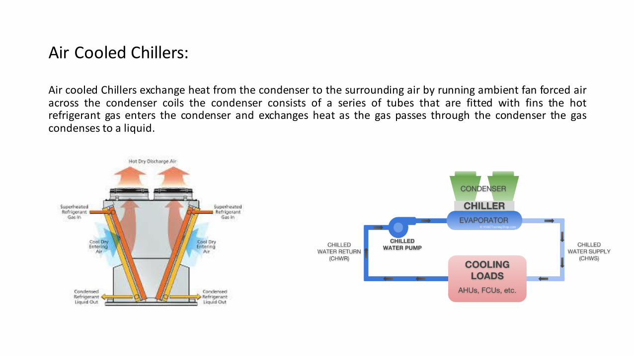
Air cooled Chillers exchange heat from the condenser to the surrounding air by running ambient fan forced airacross the condenser coils the condenser consists of a series of tubes that are fitted with fins the hotrefrigerant gas enters the condenser and exchanges heat as the gas passes through the condenser the gascondenses to a liquid.
Air Cooled Chillers:

Water cooled Chillers exchange heat from the condenser by running water (condenser water) that is derived from aevaporative type cooling tower through the condenser vessel.
The condenser consists of a series of tubes contained within the vessel (shell and tube) that the condenser coolingwater passes through, the hot refrigerant gas enters the condenser and exchanges heat to the condenser water asthe gas passes through the condenser the gas condenses to a liquid.
Water Cooled Chillers:

Selecting a Chilled Water System
Which system type is best for your application:
Air cooled, or Water cooled?
There’s no single answer, HVAC system designers need to ask a lot of questions before advocating one type of system over another.
The obvious equipment choice is sometimes over-ruled by unique project factors including:
• Available space
• Capacity
• Maintenance/running costs.
• Acoustic considerations
• Ambient conditions
• Energy efficiency
• Longevity
• Water availability, conservation & cost

Considerations:
Spacial
Air Cooled:
Air cooled chilled water plant requires a reduced plant footprint when compared to water cooled systems. Air-cooled systems require plant space exposed to the atmosphere with enough ventilation space toaccommodate separated intake and discharge airstreams.
Water Cooled:Water cooled chilled water plant requires additional plant footprint in comparison to air cooled systems. Watercooled systems require an enclosed plant room to house chillers and plant space exposed to atmosphere toaccommodate cooling towers with enough ventilation space for separated intake and discharge airstreams.

Capacity:
Air-cooled:
Typically available in sizes ranging from 25 to 2000 kW.
Water-cooled:
Typically available in sizes ranging from 35 to 15,000 kW.
Maintenance Costs:
Air-cooled Chillers:
Have substantially reduced maintenance costs in comparison to water cooled. This is due to reduced plant andequipment required to operate system.
Water-cooled Chillers:
Require additional pumps and independent Cooling Towers. They have additional maintenance demands:water treatment, chiller condenser-tube cleaning, tower mechanical maintenance. Systems that use opencooling towers must have a water treatment program to prevent contaminants such as bacteria and algae.

Acoustic Considerations:
Air-cooled :
Air cooled plant needs to be located in external plant areas and compressor and fan noise can be an issue to surrounding neighbours with strict guidelines in force with regards to maximum noise levels that can be generated
noise can be treated by incorporating acoustic louvres attenuators and acoustic screening however this can be costly
Water-cooled :
Water cooled plant is generally contained within plantroom with only cooling towers external to the plantroom noise from cooling towers can be treated once again with acoustic screening discharge attenuators and specialised low noise fan selections
Ambient Conditions:
Air Cooled: Air cooled condensers performance is directly related to dry bulb temperature. Standard design conditions for air cooled chillers is 35°C. Chillers can operate up to 46°C with options available to introduce high ambient selections up to 55°C which incorporate sub coolers, oversized electrical equipment ventilation to switchboards and controls
It should be noted that capacity of chillers will be derated as temperature rises above 35°C
Water Cooled:Cooling Tower efficient operation is directly affected by the wet bulb temperature. The amount of evaporation,and hence heat transfer, depends on the wet bulb temperature. Cooling Towers are generally selected with a24°C wet bulb temperature in Perth.
Note cooling tower performance will be further covered in section 2 of presentation

Energy Efficiency:
Chillers plants are often a significant portion of a buildings energy usage, with 15-20% of total energy used instandard buildingoperation being for cooling.
Water-cooled chillers are typically more energy efficient than air-cooled chillers. The refrigerant condensingtemperature in an air-cooled chiller is dependent on the ambient dry-bulb temperature.
The condensing temperature in a water-cooled chiller is dependent on the condenser-water temperature,which is dependent on the ambient wet-bulb temperature. Since the wet-bulb temperature is oftensignificantly lower than the dry-bulb temperature, the refrigerant condensing temperature (and pressure) in awater-cooled Chillercan be lower than in an air-cooled Chiller.
The lower condensing temperature, and therefore lower condensing pressure, means that the compressorneeds to do less work and, subsequently, consumes less energy. This efficiency advantage may lessen duringnight time operation because the dry-bulb temperature tends to drop faster than the wet-bulb temperature.

Longevity:
Air-cooled Chillers last 15 to 20 years.
Air-cooled Chillers operate outdoors, at higher condenser pressure.
Water-cooled Chillers last 20 to 30 years.
Water-cooled Chillers are typically installed indoors and operate at lower condenser fluid pressure
The above estimates are subject to hours of use and maintenance regimes

Water Availability / Conservation:
Water availability, cost, quality and environmental requirements as well as potential additionalconstruction complexity, all play a role in system selection.
Water cooled systems use cooling towers which consume large quantities of water through the heatexchange process (evaporation) and bleed rates to control concentrations of total dissolved solids(TDS) that result due to evaporation process
Since air-cooled Chillers do not require water, they are often a preferred choice in locations wherethere is a water shortage, low quality water or the water is very expensive .
In Summary:
Air-cooled system advantages include:
• Lower maintenance costs
• A prepackaged system for easier design and installation.
• No ongoing water supply requirements
Water-cooled system advantages include:
• Greater energy efficiency
• Larger capacities
• Longer equipment life.
It’s important for system designers to take all factors into consideration to make sure the Chiller type and
configuration that ultimately gets selected, balances all the objectives over the long term.

Chiller efficiency has steadily increased mainly due to improvements in compressor and heat exchanger technology, along with better controls. Below graph shows improvement in chiller efficiency from 1970’s to present.
To optimise chiller selection for high performance buildings, the most accurate method is to carry out a thermal simulation of a building to determine the annual cooling load profile under different ambient conditions.
Chiller Efficiency

Co-efficient of Performance:
Co-efficient of performance (COP) is a measure of the energy efficiency of a system. Calculation of Chiller co-efficient of performance (COP) is determined by dividing the refrigeration capacity (in Watts) by electrical inputpower (in Watts) to gain a more accurate analysis of energy performance. An assessment of system COPincluding chiller and pumps, provides a more reflective outcome.

Variable Speed Variable flow Chillers:
High levels of energy efficiency that are being achieved in modern chiller plants are largely being achieved byimproved vessel design, compressor design, the introduction of variable speed compressors and variablechilled and condenser water flow strategies.
Given that the chiller plant rarely if ever operates at peak load the ability of systems to ramp down and operateefficiently at capacity's below peak demand is essential to achieving an energy efficient system
Variable frequency drives fitted to the compressor enables chillers to be efficiently turned down to 20% ofcapacity and as low as 10% when hot gas bypass is introduced.
Peak chiller COP’s are generally achieved in the operating range of 40 - 80% in the case of multiple chillersystem staging of chillers to operate chillers within these ranges achieves optimum energy efficiency.
Chillers selected with variable chilled and condenser water flow enables pumps to ramp down relative tochiller loading the reduced water flows result in considerable pump energy savings


Chiller Staging:
Chiller staging is vital in establishing optimum system performance.
Tabulating of system co efficient of performance (COP) across chiller configurations facilitates initial optimum stage up and stage down set points for commissioning purposes
During the first year of operation staging should be reviewed and tuned in to actual building performance
Chiller sizing and Configuration:
Chillers are selected to:
• meet peak load requirements as determined via the heat load calculations
• part load requirements determined via energy modelling
The importance of considering part load operation cannot be underestimated as the majority of the time chillers will in a building operating within normal working hours will operate below 50% of load
• Chiller configuration required to meet redundancy requirements
in critical applications such as hospitals chiller configuration will be N + 1 ie failure of any chiller will maintain 100% of capacity. in commercial building application to achieve PCA premium grade buildings must maintain 60% of capacity on failure of largest chiller


Minimum Chilled Water Loop Volume:
At low load operation chiller capacity at minimum turndown may exceed building load which if not addressed in the design will result in chillers short cycling
Chiller manufacturers nominate maximum starts per hour and minimum run time. System should be designed to incorporate a total system water volume (inertia) that provides minimum requirement to facilitate maximum starts per hour and run time.
system volumes can be addressed is by the use of buffer tanks or Locating bypass valves remote from chillers and using volume of flow and return pipework to increase total volume
Calculation of minimum water volume
V = (N x 60 x Z) / (4.18 x dt)
V = total water volume (Litres)N = Capacity of the chiller’s minimum turndown (kW)Z = Minimum allowable running time (minutes)dt = Temp difference at minimum part load condition


Buffer Tanks:
Installation of Buffer tanks to return line of chilled water system increase system total volume


Plant Layout:
System design must take into account cornerstones of best practice plant layout:
• Ergonomic considerations
• Service and maintenance access
• Plant failure / end of life replacement
• Service Walkways


Cooling Tower 101
• Types of Cooling Towers• Water Usage
• Sound• Locating Cooling Towers• Requirements of AS 3666

Cooling Tower 101
An enclosed device for cooling a fluid or refrigerant by evaporation; used in water cooled refrigeration, air conditioning, and industrial process systems
Definition of a Cooling Tower

Open CircuitOr Closed Circuit?

• Use plastic fill, to create a large surface area to evaporate water by mixing with an air stream.
• Most common type of cooling Tower• Cheapest• Lightest• Most efficient (smallest/kW)• The water used for the cooling process is in direct
contact with the air, called open circuit.
Open Circuit:
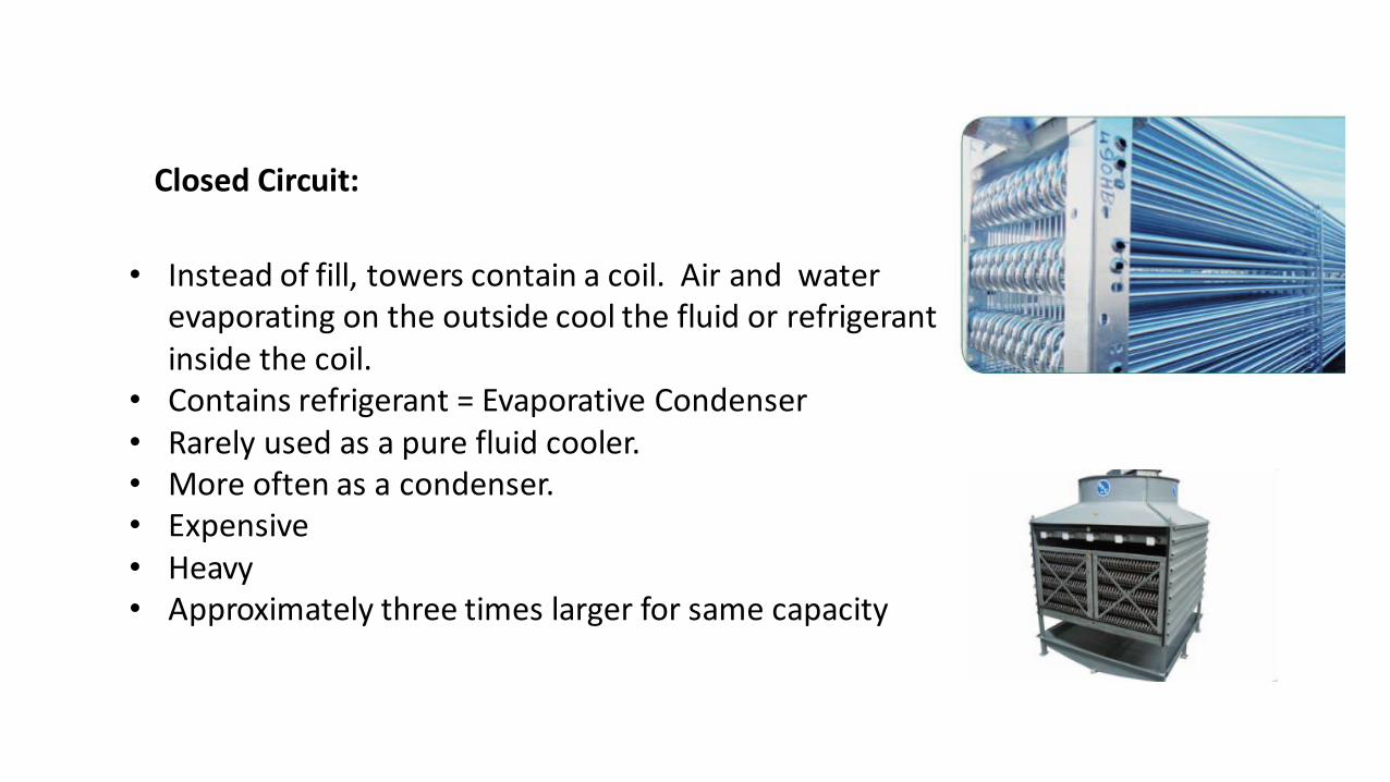
Closed Circuit:
• Instead of fill, towers contain a coil. Air and water evaporating on the outside cool the fluid or refrigerant inside the coil.
• Contains refrigerant = Evaporative Condenser • Rarely used as a pure fluid cooler.• More often as a condenser.• Expensive• Heavy• Approximately three times larger for same capacity

Cooling Tower Selection Criteria
• Quantity of water to be cooled l/s
or
• Heat of Rejection kW
• Entering water temp (°C)
• Leaving water temp (°C)
• Ambient entering air wet bulb temp (°C)
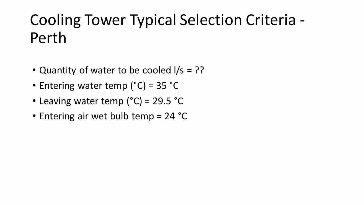
Cooling Tower Typical Selection Criteria -Perth
• Quantity of water to be cooled l/s = ??
• Entering water temp (°C) = 35 °C
• Leaving water temp (°C) = 29.5 °C
• Entering air wet bulb temp = 24 °C

Range and Approach
Two important terms:
Range (K): Difference between entering and leaving water temperatures
Approach (K): Difference between leaving water and ambient wet bulb temperatures

The Effect of Approach on Cooling Tower Size
Source AIRAH Application Manual DA17

Tower water usage
• The evaporation and water usage of a tower is directly proportional to the heat of rejection.
• It is calculated by Heat of rejection / Enthalpy of vaporisation of H2O (2402 kJ/litre).
• Quick and easy way is 1.5 x Heat Rejection = Litres / Hour

Types of Mechanical Draft Towers
Forced Draft Tower• One or more fans are located at the air
inlet to force air into the tower.• Fans are high volume, high static but
use a lot of power.• Suited to towers located inside
plantrooms.
Induced Draft Tower• One or more fans are located in the air
outlet to induce air flow through the air inlets
• Axial fans, high volume, low static, low power.

Crossflow and CounterflowAxial Fan Cooling Towers
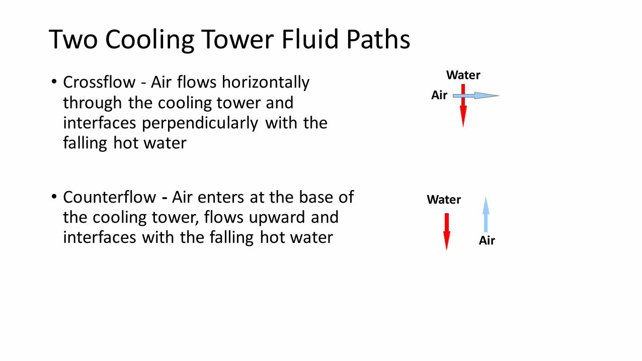
Two Cooling Tower Fluid Paths
• Crossflow - Air flows horizontally through the cooling tower and interfaces perpendicularly with the falling hot water
• Counterflow - Air enters at the base of the cooling tower, flows upward and interfaces with the falling hot water
Water
Air
Water
Air

Cross-flow Principle of Operation
Hot Water In Hot Water In
Moist WarmAir Out
Plenum
Cold WaterOut
Dry Air InDry Air In
Water
Air
Air Entry
Air Entry
Air Pathway

Cross-flow Configuration
Direct, Belt or Gearbox Drive
Crossflow Fill Incorporating Eliminator
Axial Fan with belt,Gearbox or Direct Drive
Gravity Feed Hot WaterBasin & Nozzles
Open PlenumSpace
Sloping Cold Basin& Connections

Advantages
• Lowest sound solution
• Ease of maintenance
• Easy, safe, simple accessAS/NZS 3666 Compliance
• Lower energy
• Fill cleanable in place
• Tolerance to water flow variation
Disadvantages
• Large footprint
• Cost
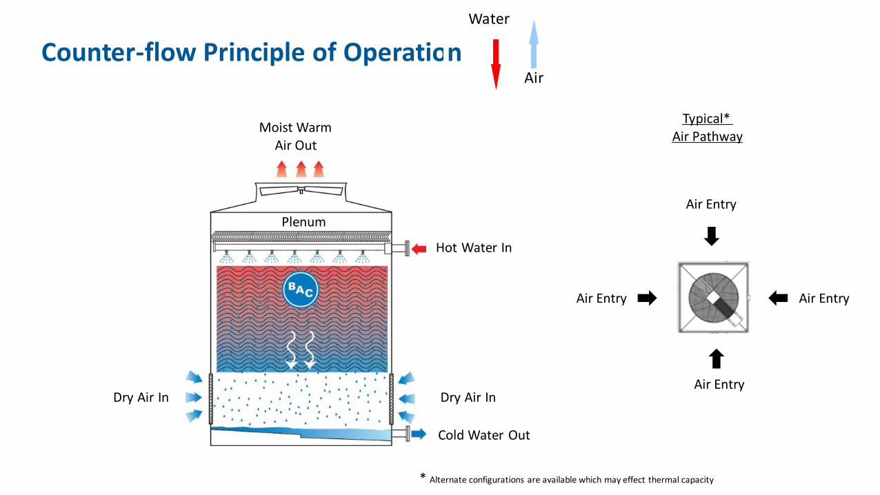
Counter-flow Principle of Operation
Hot Water In
Moist WarmAir Out
Plenum
Cold Water Out
Dry Air InDry Air In
Water
Air
Air Entry
Air Entry
Air EntryAir Entry
Typical* Air Pathway
* Alternate configurations are available which may effect thermal capacity

Counter-flow Configuration
Counter-flow Fill
Hot Water Spray Nozzles
Counter-flow Eliminators
Axial Fan with belt,Gearbox or Direct Drive
Sloping Cold Basin& Connections

Advantages
• Efficient Heat Transfer
• Reduced Footprint
• Lowest Cost
Disadvantages
• Access for maintenance
• Increased energy due to pump head/spray nozzles
• High static pressure losses

Sou
nd
Cross-flow Counter-flow
Water distribution by gravity with continual fill path to CWB. No high frequency splash noise
Easy access to fill for inspection and maintenance
The center plenum area is large enough to stand and traverse easily lessening the challenges of confined space
High frequency noise production due to falling water. Partial compensation with water silencers
Access to fill for inspection and maintenance can be difficult. Blocks of fill need to be removed.
Very limited space is available to access vital components making access for maintenance
Side-by-side ComparisonIn
spe
ctio
nA
cce
ss
. A counterflow tower by nature has.

Ene
rgy
Cross-flow Counter-flow
Gravity flow through nozzles for water distribution allows lower pumping head and operational cost
Spray distribution and path increases water droplet size to aid coalescence and reduce drift
Larger plenum area needs increase the footprint of the cooling towers
Pumping required for atomisation of water through nozzles for correct distribution across fill
Spray distribution mist located in the high velocity air path can promote drift of harmful droplet size
Smaller plenums reduce the overall size and cost, making counter-flow towers very economical and beneficial for small areas
Side-by-side ComparisonH
ygie
ne
Foo
tpri
nt

Sound Considerations
Water Fall
Fan Noise
Water Cascade
Crossflow Counterflow
Low Water Noise
Fan Noise
High Water Noise
High Water Noise

Sound Attenuation - Fan NoiseFan Noise
• Fan Options• Standard Fan
• Low Sound Fan
• Whisper Quiet Fan
• Sound Attenuation

Sound Attenuation – Water NoiseCrossflow vs Counterflow
Water Splash MatsIntake Sound Attenuation
Sound Attenuation or Larger Tower?
It is generally a lot cheaper to use a standard fan in a larger tower and slow it down than to add Whisper Quiet fans and/or attenuators.
You also get the added advantage of lower power and running costs, plus spare capacity if you need it.

Tower layout
• Manufacturers provide guidelines for space requirements between solid and louvred walls.
• Don’t forget to allow access for maintenance
• Make sure the top of the tower discharge is equal too or higher than any surrounding walls.
• If towers need to be pushed hard against one another the losses can be over come with custom towers with increased louvre height.
• When towers are located in a well, we would like the downward air velocity around the tower, to be less than 1.5 m/s.

AS 3666
• Cooling towers shall be fabricated from corrosion-resistant materials and for ease of maintenance, particularly cleaning fill, water distribution, basin and sumps.
• Internal surfaces shall be smooth faced and constructed to facilitate cleaning.
• Provision shall be made for quick draining and refill.
• Drains and basins shall be graded to prevent collection of water.
• Drift shall be less than 0.002% of the recirculating flow rate.
“Cooling towers that undergo retrofit of components such as fill, basins or eliminators
or any upgrade for performance shall be required to meet all requirements associated
with cooling towers, of this Standard.”
Source AS 3666.2011.1
Questions?

Thank you for attending;please stay for refreshments in the foyer.
Thank you to our Sponsor
