pressure and speed limits for hydrostatic units -...
TRANSCRIPT
Applications Manual
Pressure and Speed Limits forHydrostatic Units
powersolutions.danfoss.com

Revision history Table of revisions
Date Changed Rev
May 2015 Danfoss layout - major update 0401
July 1997 D
Applications ManualPressure and Speed Limits for Hydrostatic Units
2 | © Danfoss | May 2015 BLN-9884 | BC00000160en-US0401
IntroductionApplications Manuals......................................................................................................................................................................4
Pressure and Speed LimitsIntroduction........................................................................................................................................................................................5Load to Life Relationships............................................................................................................................................................. 5Pressure Limits for Hydraulic Units............................................................................................................................................ 6Speed Ratings for Hydraulic Units........................................................................................................................................... 10
Motor Performance at Low SpeedMotor Performance at Low Speed...........................................................................................................................................15
Bypass Valve Speed LimitationsBypass Valve Speed Limitations............................................................................................................................................... 16
Inlet Vacuum LimitsInlet Vacuum Limits.......................................................................................................................................................................17
Dynamic BrakingDynamic Braking............................................................................................................................................................................ 18
Displacement Control:............................................................................................................................................................ 19
Case Drain Pressure LimitsCase Drain Pressure Limits..........................................................................................................................................................20
Applications ManualPressure and Speed Limits for Hydrostatic Units
Contents
© Danfoss | May 2015 BLN-9884 | BC00000160en-US0401 | 3
Applications Manuals
Content included in these manuals
These applications manuals provide design theory and detailed calculations for building hydraulicallypowered machines.
The original document was written as one manual with four sections.
The current set of manuals includes the four documents listed below. The section numbers from theoriginal document are listed in parenthesis after the current document title.• Selection of Driveline Components BLN-9885 (originally Section 1)• Pressure and Speed Limits for Hydrostatic Units BLN-9884 (originally Section 2)• Transmission Circuit Recommendations BLN-9886 (originally Section 4)• Fluids and Lubricants 520L0463 (originally Section 3)
Other Reference Manuals• Hydraulic Fan Drive Systems Technical Information 520L0824• Hydraulic Fan Drive Systems Design Guidelines 520L0926
Applications ManualPressure and Speed Limits for Hydrostatic Units
Introduction
4 | © Danfoss | May 2015 BLN-9884 | BC00000160en-US0401
Introduction
In order to properly size hydrostatic units for power transmission applications, it is necessary to select anappropriate design pressure and design speed. The selection of these design parameters are affectedby required unit life. The purpose of this guideline is to assist system integrators in the selection ofdesign pressure and design speed to optimize hydraulic unit utility and to provide satisfactorytransmission life.
Danfoss Power Solutions publishes continuous (1) ratings and maximum ratings for both pressure andspeed capabilities. Application decisions are made by considering both typical and extreme operatingconditions. Predicted unit life, based on the design pressure and speed, is compared to the required unitlife for the application. Satisfactory design criteria must be obtained for both normal rated and maximumvalues.
(1) The term “continuous” refers to the speed ratings of Danfoss Power System products, but not to theirpressure ratings.
Load to Life Relationships
System pressure is the dominant operating variable affecting hydraulic unit life. High pressure, whichresults from high load, reduces life in a manner similar to many mechanical assemblies such as enginesand gear boxes. There are load-life relationships for the rotating group and for the shaft bearings whichmust be considered separately.
The graph Hydraulic Unit Life vs System Pressure shows the general relationship between life expectancyand system pressure. The upper limit of hydraulic unit life is established by fatigue and wear of therotating group, bearing fatigue, or wear and deterioration of other parts, each with their own load-liferelationship. At high system pressures, fatigue and wear of the rotating group is the limiting factor,while bearing failure becomes the limiting factor at intermediate pressures. It is important to note theshallow slope of the life curve at high system pressures which indicates a significant decrease in life witha slight increase in pressure.
Actual life is also affected by a combination of factors relating to fluid quality as shown in Hydraulic UnitLife vs System Pressure by the curves corresponding to less-than-ideal fluid quality. Factors relating to fluidquality include temperature, contamination (heat, hard particle, water, chemical, and entrained air),viscosity, and lubrication properties. Most of these factors are also influenced by operating pressure.System design should take these factors into account. Technical Information Manuals (Hydraulic Fluidsand Lubricants 520L0463, Experience with Biodegradable Hydraulic Fluids 520L0465, and Design Guidelinefor Hydraulic Fluid Cleanliness 520L0467) cover this subject in more detail.
Applications ManualPressure and Speed Limits for Hydrostatic Units
Pressure and Speed Limits
© Danfoss | May 2015 BLN-9884 | BC00000160en-US0401 | 5

Hydraulic Unit Life vs System Pressure
Rotating groupFatigue & WearBearing Fatigue
Other C
omponents
Normal Limitof Unit Life
Marginal Fluid Quality
Poor Fluid Quality
Life Expectancy (Time)
Sys
tem
Ope
ratin
g
P
ress
ure
Pressure Limits for Hydraulic Units
The following definitions of hydraulic unit pressure capability and associated life requirements areprovided to assist in sizing transmission components. Contact a Danfoss Power Solutions representativewith your machine parameters if there is a question regarding typical load cycles.
In closed circuit hydrostatic units, System Pressure is the differential (delta) pressure between the highand low pressure work ports. It is the measure of the pressure available to accept or provide torquethrough the conversion of mechanical to/from hydraulic power. Zero System Pressure is the conditionwhere both sides of the hydrostatic loop are at equal pressure, typically at Charge Pressure. SystemPressure is the dominant operating variable affecting hydraulic unit life and performance. High systempressure, which results from high load, reduces expected life. Hydraulic unit life depends on the speedand normal operating, or weighted average, pressure which can only be determined from a duty cycleanalysis.
In open circuit units, System Pressure is the gauge pressure of the working port since the low pressurereference is zero gage pressure at the reservoir.
In closed circuit hydrostatic units, it is common to provide a flow source at a moderate pressure toprovide makeup flow (charge flow) for the hydrostatic loop. The pressure of this flow source is calledCharge Pressure and is usually measured in terms of delta pressure above case pressure. The lowerpressure side of the hydrostatic power loop will typically be at, or near, charge pressure. In open circuitsystems, charge pressure may be considered to be the pressure available to the inlet of the pump or theoutlet of the motor. It may be either below atmospheric (0 Gauge Pressure) or above. If the chargepressure is above atmospheric, it is often known as Boost Pressure for a pump or Back Pressure for amotor.
In closed circuit units, Minimum Pressure is the gauge pressure that must be maintained in the workingports under all operating conditions to avoid excessive cavitation and to provide lubrication for slidingcomponents. Minimum pressure is typically less than Charge Pressure. Minimum Pressure limits areidentified in the Technical Information Bulletin for each product. Unless otherwise specified, MinimumPressure is defined as 10 bar [150 psig].
In open circuit units, Minimum Inlet Pressure is the minimum allowable absolute pressure in the pumpsuction line. The minimum inlet pressure must be evaluated in both steady state, and transientconditions; note that when pump displacement increases, inlet pressure is reduced due to acceleration offluid in the inlet line.
Application Pressure is the highest intermittent pressure defined for a given application; and is the highpressure relief, pressure limiter, or pressure compensator setting typically defined within the order codeof the pump or motor. It is determined by the maximum machine load demand. Application Pressure isthe "applied" System Pressure (delta pressure) at which the driveline generates the maximum calculatedpull or torque, or at which maximum loads move in the application. Application Pressure is typicallydetermined from the maximum design loads of the vehicle driveline or work function components.Application Pressure is assumed to occur for a small percentage of operating time, usually less than 2% ofthe total.
Applications ManualPressure and Speed Limits for Hydrostatic Units
Pressure and Speed Limits
6 | © Danfoss | May 2015 BLN-9884 | BC00000160en-US0401
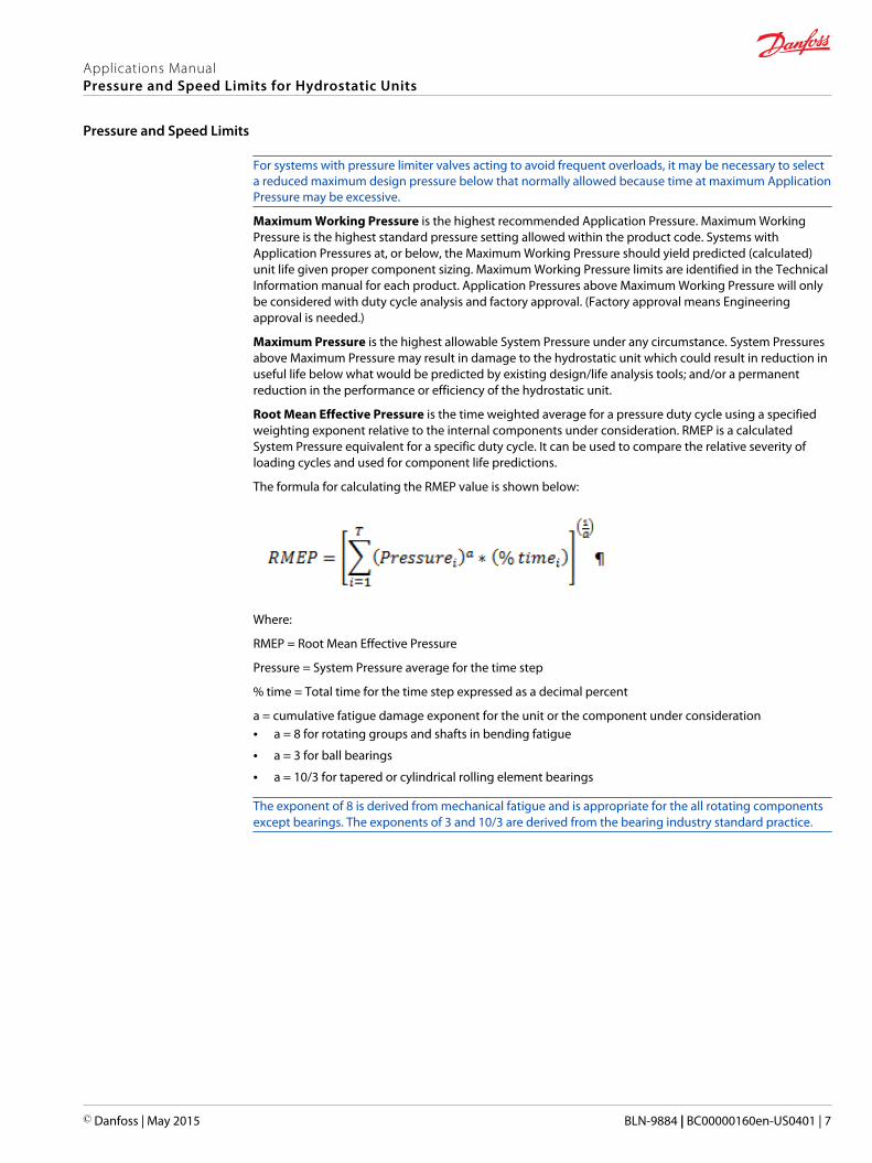
For systems with pressure limiter valves acting to avoid frequent overloads, it may be necessary to selecta reduced maximum design pressure below that normally allowed because time at maximum ApplicationPressure may be excessive.
Maximum Working Pressure is the highest recommended Application Pressure. Maximum WorkingPressure is the highest standard pressure setting allowed within the product code. Systems withApplication Pressures at, or below, the Maximum Working Pressure should yield predicted (calculated)unit life given proper component sizing. Maximum Working Pressure limits are identified in the TechnicalInformation manual for each product. Application Pressures above Maximum Working Pressure will onlybe considered with duty cycle analysis and factory approval. (Factory approval means Engineeringapproval is needed.)
Maximum Pressure is the highest allowable System Pressure under any circumstance. System Pressuresabove Maximum Pressure may result in damage to the hydrostatic unit which could result in reduction inuseful life below what would be predicted by existing design/life analysis tools; and/or a permanentreduction in the performance or efficiency of the hydrostatic unit.
Root Mean Effective Pressure is the time weighted average for a pressure duty cycle using a specifiedweighting exponent relative to the internal components under consideration. RMEP is a calculatedSystem Pressure equivalent for a specific duty cycle. It can be used to compare the relative severity ofloading cycles and used for component life predictions.
The formula for calculating the RMEP value is shown below:
Where:
RMEP = Root Mean Effective Pressure
Pressure = System Pressure average for the time step
% time = Total time for the time step expressed as a decimal percent
a = cumulative fatigue damage exponent for the unit or the component under consideration• a = 8 for rotating groups and shafts in bending fatigue
• a = 3 for ball bearings
• a = 10/3 for tapered or cylindrical rolling element bearings
The exponent of 8 is derived from mechanical fatigue and is appropriate for the all rotating componentsexcept bearings. The exponents of 3 and 10/3 are derived from the bearing industry standard practice.
Applications ManualPressure and Speed Limits for Hydrostatic Units
Pressure and Speed Limits
© Danfoss | May 2015 BLN-9884 | BC00000160en-US0401 | 7
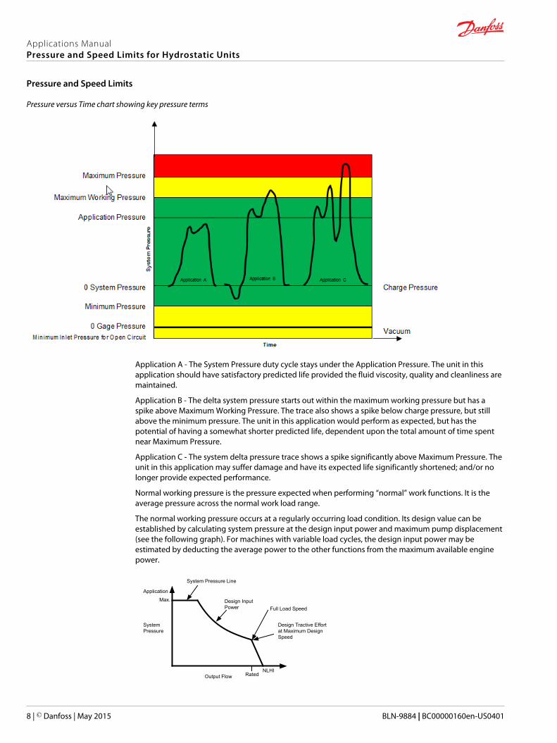
Pressure versus Time chart showing key pressure terms
Application A - The System Pressure duty cycle stays under the Application Pressure. The unit in thisapplication should have satisfactory predicted life provided the fluid viscosity, quality and cleanliness aremaintained.
Application B - The delta system pressure starts out within the maximum working pressure but has aspike above Maximum Working Pressure. The trace also shows a spike below charge pressure, but stillabove the minimum pressure. The unit in this application would perform as expected, but has thepotential of having a somewhat shorter predicted life, dependent upon the total amount of time spentnear Maximum Pressure.
Application C - The system delta pressure trace shows a spike significantly above Maximum Pressure. Theunit in this application may suffer damage and have its expected life significantly shortened; and/or nolonger provide expected performance.
Normal working pressure is the pressure expected when performing “normal” work functions. It is theaverage pressure across the normal work load range.
The normal working pressure occurs at a regularly occurring load condition. Its design value can beestablished by calculating system pressure at the design input power and maximum pump displacement(see the following graph). For machines with variable load cycles, the design input power may beestimated by deducting the average power to the other functions from the maximum available enginepower.
System Pressure Line
Design InputPower
Output Flow Rated
Design Tractive Effortat Maximum DesignSpeed
NLHI
Full Load Speed
Max.
Application
SystemPressure
Applications ManualPressure and Speed Limits for Hydrostatic Units
Pressure and Speed Limits
8 | © Danfoss | May 2015 BLN-9884 | BC00000160en-US0401

The preferred method of selecting an Application Pressure requires duty cycle information for theapplication. A duty cycle is a means of quantifying the pressure and speed demands of a particularsystem on a percent time basis. The duty cycle data is weighted to reflect the preponderant influence ofpressure on unit life. Using the rotating group and shaft bearing load-life tools developed by DanfossPower Solutions for the various product families, the optimum Application Pressure can be selectedbased on the required life expectancy for the application.
If an external side load is expected on the shaft, its magnitude and direction with respect to theswashplate must be known when calculating expected bearing life.
It is very important that the duty cycle information be as accurate as possible due to the exponentialeffect that pressure has on the life of the rotating group.
In the absence of duty cycle data, allowable pressure limits for design can usually be established basedon the maximum and normal working load in the drive. This assumes that the duty cycle falls within atypical band width. By using this approach, two “pressure limit” values can be used to predict a successfulapplication when machine life requirements are known.
The following table is provided to aid the engineer in understanding and selecting appropriate designpressure for a given component life requirement. These values are derived from the load-life relationshipfor the rotating groups of the various Danfoss Power Solutions product families at 1800 rpm shaft speedand no external shaft loads. Unit life is given in terms of L20 hours (80% survival) for the rotating groupbased on published recommendations for fluid cleanliness and viscosity. Using these guidelines, thesystem must meet both the maximum and continuous pressure limits to be considered acceptable.
Prototype test programs to verify operating pressures and predicted unit life are strongly recommendedprior to finalizing any hydrostatic drive design.
Applications ManualPressure and Speed Limits for Hydrostatic Units
Pressure and Speed Limits
© Danfoss | May 2015 BLN-9884 | BC00000160en-US0401 | 9
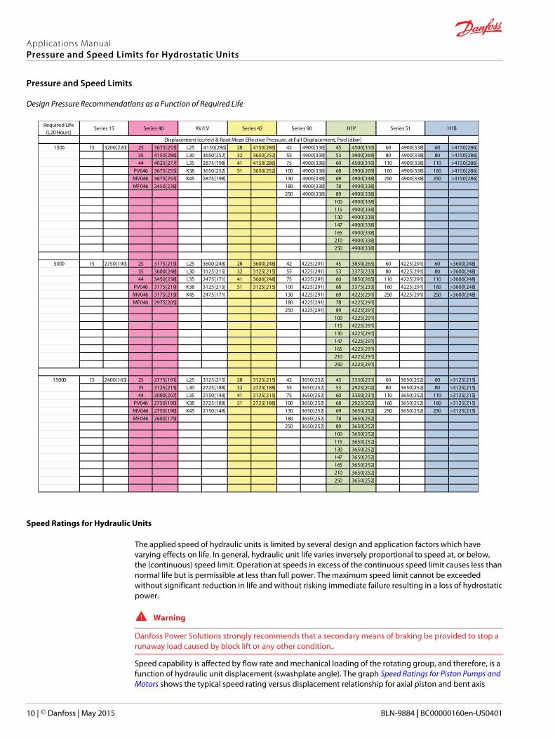
Design Pressure Recommendations as a Function of Required Life
1500 15 3200 [220] 25 3675 [253] L25 4150 [286] 28 4150 [286] 42 4900 [338] 45 4500 [310] 60 4900 [338] 60 >4150 [286]35 4150 [286] L30 3650 [252] 32 3650 [252] 55 4900 [338] 53 3900 [269] 80 4900 [338] 80 >4150 [286]44 4025 [277] L35 2875 [198] 41 4150 [286] 75 4900 [338] 60 4500 [310] 110 4900 [338] 110 >4150 [286]
PV046 3675 [253] K38 3650 [252] 51 3650 [252] 100 4900 [338] 68 3900 [269] 160 4900 [338] 160 >4150 [286]MV046 3675 [253] K45 2875 [198] 130 4900 [338] 69 4900 [338] 250 4900 [338] 250 >4150 [286]MF046 3450 [238] 180 4900 [338] 78 4900 [338]
250 4900 [338] 89 4900 [338]100 4900 [338]115 4900 [338]130 4900 [338]147 4900 [338]165 4900 [338]210 4900 [338]250 4900 [338]
5000 15 2750 [190] 25 3175 [219] L25 3600 [248] 28 3600 [248] 42 4225 [291] 45 3850 [265] 60 4225 [291] 60 >3600 [248]35 3600 [248] L30 3125 [215] 32 3125 [215] 55 4225 [291] 53 3375 [233] 80 4225 [291] 80 >3600 [248]44 3450 [238] L35 2475 [171] 41 3600 [248] 75 4225 [291] 60 3850 [265] 110 4225 [291] 110 >3600 [248]
PV046 3175 [219] K38 3125 [215] 51 3125 [215] 100 4225 [291] 68 3375 [233] 160 4225 [291] 160 >3600 [248]MV046 3175 [219] K45 2475 [171] 130 4225 [291] 69 4225 [291] 250 4225 [291] 250 >3600 [248]MF046 2975 [205] 180 4225 [291] 78 4225 [291]
250 4225 [291] 89 4225 [291]100 4225 [291]115 4225 [291]130 4225 [291]147 4225 [291]165 4225 [291]210 4225 [291]250 4225 [291]
15000 15 2400 [165] 25 2775 [191] L25 3125 [215] 28 3125 [215] 42 3650 [252] 45 3350 [231] 60 3650 [252] 60 >3125 [215]35 3125 [215] L30 2725 [188] 32 2725 [188] 55 3650 [252] 53 2925 [202] 80 3650 [252] 80 >3125 [215]44 3000 [207] L35 2150 [148] 41 3125 [215] 75 3650 [252] 60 3350 [231] 110 3650 [252] 110 >3125 [215]
PV046 2750 [190] K38 2725 [188] 51 2725 [188] 100 3650 [252] 68 2925 [202] 160 3650 [252] 160 >3125 [215]MV046 2750 [190] K45 2150 [148] 130 3650 [252] 69 3650 [252] 250 3650 [252] 250 >3125 [215]MF046 2600 [179] 180 3650 [252] 78 3650 [252]
250 3650 [252] 89 3650 [252]100 3650 [252]115 3650 [252]130 3650 [252]147 3650 [252]165 3650 [252]210 3650 [252]250 3650 [252]
Displacement (cc/rev) & Root Mean Effective Pressure, at Full Displacement, Psid [dbar]
Series 15 Series 40 Series 51 H1BRequired Life(L20 Hours)
KV/LV Series 42 Series 90 H1P
Speed Ratings for Hydraulic Units
The applied speed of hydraulic units is limited by several design and application factors which havevarying effects on life. In general, hydraulic unit life varies inversely proportional to speed at, or below,the (continuous) speed limit. Operation at speeds in excess of the continuous speed limit causes less thannormal life but is permissible at less than full power. The maximum speed limit cannot be exceededwithout significant reduction in life and without risking immediate failure resulting in a loss of hydrostaticpower.
W Warning
Danfoss Power Solutions strongly recommends that a secondary means of braking be provided to stop arunaway load caused by block lift or any other condition..
Speed capability is affected by flow rate and mechanical loading of the rotating group, and therefore, is afunction of hydraulic unit displacement (swashplate angle). The graph Speed Ratings for Piston Pumps andMotors shows the typical speed rating versus displacement relationship for axial piston and bent axis
Applications ManualPressure and Speed Limits for Hydrostatic Units
Pressure and Speed Limits
10 | © Danfoss | May 2015 BLN-9884 | BC00000160en-US0401
hydraulic units. In general, speed capability increases as displacement decreases, up to a peak value atintermediate displacements.
The Rated Continuous Speed Limit is the highest speed recommended at full power conditions. Thisrating defines the highest speed at which normal life can be expected. Continuous full power operationapplies at the conditions defined by continuous pressure.
Operation above the rated speed limit is expected at reduced power, as engine speed increase (forpumps) and reduced volumetric loss (for motors) will produce increased motor/vehicle speed at low, ornegative, power. Some reduction of life would be expected at full power when operating above the ratedspeed limit. For normal systems, working power level, and resulting system pressures will be low whenapplied properly, and time above the rated speed limit will be low.
The rated speed limit varies with swashplate angle up to the reduced angle continuous maximum value.The upward sloping speed characteristic is derived from the kinematic design parameters of axial pistonpumps and motors. They define the conditions at which normal operation is expected, based onsufficient charge pressure. Normally, pumps are not applied at reduced angle speed ratings because theyfrequently must operate at the highest speed and maximum angle simultaneously.
The maximum speed rating is the highest operating speed recommended and cannot be exceededwithout severe reduction of unit life, or without risking premature failure and loss of drive. Operatingconditions between continuous and maximum speed limits should be restricted to less than full powerand to limited periods of time. For most drive systems, maximum motor speed occurs during downhillbraking or negative power conditions.
The maximum speed rating varies with swashplate angle up to the reduced angle maximum value. Atthis speed, conditions of marginal lubrication may exist when system pressure is low. Also, rotationalforces are high and may cause abnormal mechanical loading and stress on the rotating group.
For all axial and bent axis units, exceeding the maximum speed limit is a safety concern when thetransmission is providing retarding power. At high swashplate angles, the maximum speed is limited byblock lift which causes a loss of drive power. This could allow dangerously high, and uncontrollable,output speed. Operation above the maximum speed limit must be avoided under all modes of operationincluding engine speed-up and reduced volumetric loss during downhill braking.
W Warning
Danfoss Power Solutions strongly recommends that a secondary means of braking be provided to stop arunaway load caused by block lift or any other condition.
Applications ManualPressure and Speed Limits for Hydrostatic Units
Pressure and Speed Limits
© Danfoss | May 2015 BLN-9884 | BC00000160en-US0401 | 11
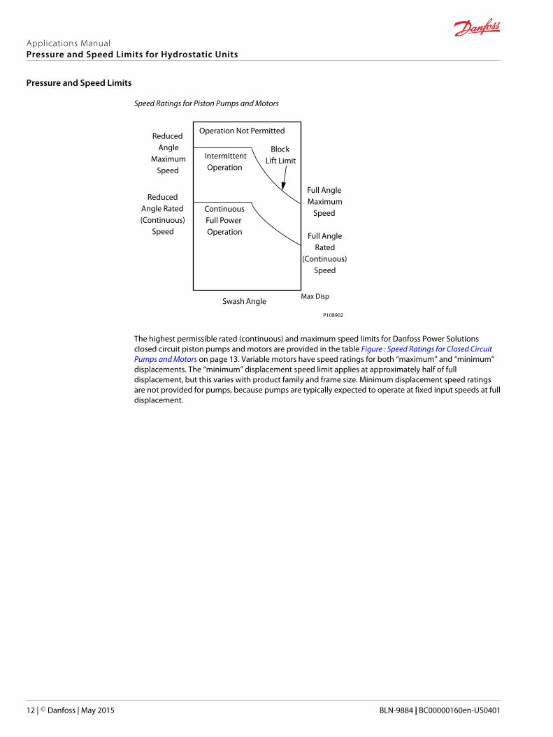
Speed Ratings for Piston Pumps and Motors
Max DispSwash Angle
Full AngleRated
(Continuous)Speed
Full AngleMaximum
Speed
IntermittentOperation
ContinuousFull PowerOperation
ReducedAngle
MaximumSpeed
ReducedAngle Rated(Continuous)
Speed
Operation Not Permitted
BlockLift Limit
P108902
The highest permissible rated (continuous) and maximum speed limits for Danfoss Power Solutionsclosed circuit piston pumps and motors are provided in the table Figure : Speed Ratings for Closed CircuitPumps and Motors on page 13. Variable motors have speed ratings for both “maximum” and “minimum”displacements. The “minimum” displacement speed limit applies at approximately half of fulldisplacement, but this varies with product family and frame size. Minimum displacement speed ratingsare not provided for pumps, because pumps are typically expected to operate at fixed input speeds at fulldisplacement.
Applications ManualPressure and Speed Limits for Hydrostatic Units
Pressure and Speed Limits
12 | © Danfoss | May 2015 BLN-9884 | BC00000160en-US0401
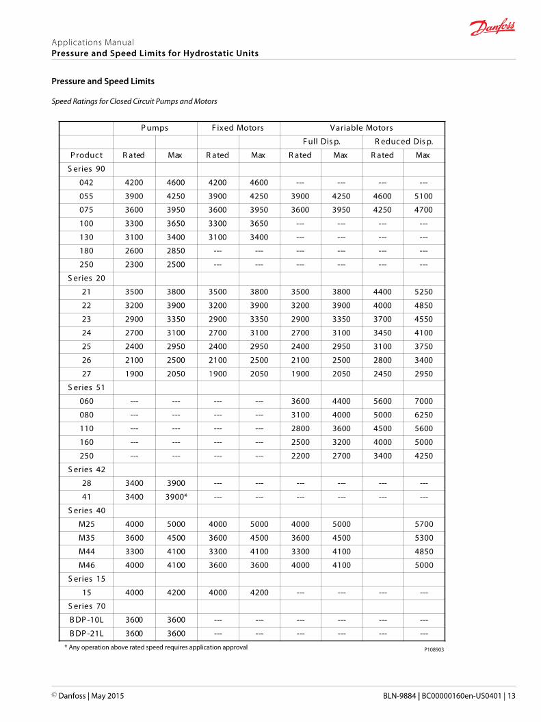
Speed Ratings for Closed Circuit Pumps and Motors
spmu sP rotoMdexi sF rotoMelbairaV
p.siDllu p.F siDdecudeR
tcudorP detaR xaM detaR xaM detaR xaM detaR xaM
09seireS
240 0024 0064 0024 0064 --- --- --- ---
550 0093 0524 0093 0524 0093 0524 0064 0015
570 0063 0593 0063 0593 0063 0593 0524 0074
001 0033 0563 0033 0563 --- --- --- ---
031 0013 0043 0013 0043 --- --- --- ---
081 0062 0582 --- --- --- --- --- ---
052 0032 0052 --- --- --- --- --- ---
02seireS
12 0053 0083 0053 0083 0053 0083 0044 0525
22 0023 0093 0023 0093 0023 0093 0004 0584
32 0092 0533 0092 0533 0092 0533 0073 0554
42 0072 0013 0072 0013 0072 0013 0543 0014
52 0042 0592 0042 0592 0042 0592 0013 0573
62 0012 0052 0012 0052 0012 0052 0082 0043
72 0091 0502 0091 0502 0091 0502 0542 0592
15seireS
060 --- --- --- --- 0063 0044 0065 0007
080 --- --- --- --- 0013 0004 0005 0526
011 --- --- --- --- 0082 0063 0054 0065
061 --- --- --- --- 0052 0023 0004 0005
052 --- --- --- --- 0022 0072 0043 0524
24seireS
82 0043 0093 --- --- --- --- --- ---
14 0043 *0093 --- --- --- --- --- ---
04seireS
52M 0004 0005 0004 0005 0004 000 05 075
53M 0063 0054 0063 0054 0063 005 04 035
44M 0033 0014 0033 0014 0033 001 04 584
64M 0004 0014 0063 0063 0004 001 04 005
51seireS
51 0004 0024 0004 0024 --- --- --- ---
07seireS
L01-PDB 0063 0063 --- --- --- --- --- ---
L12-PDB 0063 0063 --- --- --- --- --- ---
* Any operation above rated speed requires application approval P108903
Applications ManualPressure and Speed Limits for Hydrostatic Units
Pressure and Speed Limits
© Danfoss | May 2015 BLN-9884 | BC00000160en-US0401 | 13
The following equations are provided to calculate motor speed limits for intermediated displacements.Although the calculated values will exceed the tabulated values at lower swashplate angles, speed limitsfrom the table should never be exceeded. The equations are valid for “maximum” as well as “rated” speedlimits and are provided for convenience of calculation.
Axial Piston Motors
NV = NM (TM / TV)1/2
or
NV = NM (DM / DV)1/2
where:
NV = Motor speed limit at reduced angle (RPM)
NM= Motor speed limit at maximum swashplate angle from Table 2 (RPM)
TV = Tangent of reduced swashplate angle
TM = Tangent of maximum swashplate angle• Tan 15° = 0.268 (Series 15 and Series 40-M25)
• Tan 16° = 0.287 (Series 40-M35 and Series 40-M44)
• Tan 17° = 0.306 (Series 90 and Series 40-M46)
• Tan 18° = 0.325 (Series-20, Series 42, and H1P)
DM= Motor displacement at maximum angle (cc/rev or in3/rev)
DV = Motor displacement at reduced angle (cc/rev or in3/rev)
Bent Axis Motors
NV = NM (SM / SV)
or
NV = NM (DM / DV)
where:
NV = Motor speed limit at reduced angle (RPM)
NM= Motor speed limit at maximum angle from Table 2 (RPM)
SV = Sine of reduced angle
SM = Sine of maximum angle, Sin 32° = 0.530 (Series 51 and H1B)
DM= Motor displacement at maximum angle (cc/rev or in3/rev)
DV = Motor displacement at reduced angle (cc/rev or in3/rev)
Applications ManualPressure and Speed Limits for Hydrostatic Units
Pressure and Speed Limits
14 | © Danfoss | May 2015 BLN-9884 | BC00000160en-US0401

Motor Performance at Low Speed
Some applications require controlled motor operation at low speeds. Generally, speeds less than 5% ofrated are considered “slow” for axial piston motors. For bent axis motors, speeds less than 2-3% of ratedare considered “slow”. Like high speed applications, a common requirement for low speed operation iscontinuous smooth output shaft rotation. However, axial piston type motors have inherent limitationswhich may provide unacceptable performance at low speeds.
The main limitation is related to the interaction of the pistons as they transition from high to low pressureacross the valve plate. As each piston makes the transition, there is a variation in the motor’s totaldisplacement. Even if system pressure remains constant, the variation in displacement results in a “torqueripple” at the motor output shaft, which is generally described as shaft cogging. As system pressureincreases, the speed at which cogging occurs also increases. Other system parameters affecting thisinherent phenomenon include inertia of the load, load fluctuations, and bulk modulus of the system (linediameter and length, line type, and fluid compressibility).
Another inherent limitation to low speed operation, common to all types of driveline components, issimply mechanical friction. For piston motors, this is largely a function of the design of the unit and themanufacturing tolerances of the rotating group parts.
As a rule of thumb, most Danfoss Power Solutions axial piston motors will operate smoothly down to~150 rpm. Some axial piston motors may run smoothly at less than 150 rpm, but performance must beverified for the specific application. Danfoss Power Solutions does not recommend that any axial pistonmotor be size to operate continuously at speeds less than 100 rpm.
The H1B and Series 51 variable displacement bent axis motors have demonstrated smooth performanceat speeds down to 50 rpm in most applications, but acceptability must be judged based on specificapplication requirements.
Because the limitation to low speed operation is inherent to all piston type motors, Danfoss PowerSolutions cannot offer “special hardware” to improve low motor speed performance. Low speedapplications should be critiqued carefully at the design phase and thoroughly tested for acceptableperformance at the prototype phase.
Applications ManualPressure and Speed Limits for Hydrostatic Units
Motor Performance at Low Speed
© Danfoss | May 2015 BLN-9884 | BC00000160en-US0401 | 15
Bypass Valve Speed Limitations
Most Danfoss Power Solutions axial piston pumps have a bypass valve which allows system fluid to becross-ported between the main “A” and “B” ports when pump input shaft rotation is not possible. Thisvalve requires manual engagement and disengagement via an external device on the pump, such as anadjustment screw or plunger. The intent of this valve is to allow a vehicle using a closed loop propelcircuit to be moved a short distance at slow speeds. Typically, this translates to loading a vehicle onto atrailer, getting a malfunctioning machine away from the work area, or out of a traffic lane.
Cross-port bypassing is required to prevent hydraulic lockup as the motor becomes a flow source whilethe vehicle is being moved (assuming the motor remains coupled to the ground via tires or tracks). Thebypass valve should not be used or referred to as a “towing valve” which implies high speed and longduration usage.
Vehicle speed limitations associated with cross-port bypassing are a function of flow rate and duration oftime. Exceeding one, or both, of these criteria can lead to failure of the transmission. Flow rate is criticalbecause the bypass valve may become saturated due to its pressure rise rate creating excessive heat. Thetemperature rise of the fluid as it passes thru the bypass valve is proportional to the square of the flowrate. (i.e., if you double the flow rate, you will increase the temperature rise rate by 4-times).
Duration is critical because there will be no charge fluid to makeup leakage in the circuit, and the systemlines will become evacuated. Because the flow rate being bypassed is a function of the motordisplacement, final drive ratio, and rolling radius; it is impossible to publish strict speed ratings for thebypass mode. Also, the circuit design will affect how quickly system fluid is lost to leakage. However, thefollowing rule of thumb for flow rate and duration has been used successfully to quantify the limitationsduring a bypass mode.
Do not operate the transmission in bypass mode at more than 10~15% of rated motor speed anddo not exceed a duration of 3~5 minutes, depending on the product. Refer to the product specificTechnical Information Manuals for details and limits.
During normal transmission operation, the bypass valve must remain fully closed. Partial opening of thevalve will cause sluggish performance and will create excessive heat in the system.
The bypass function is standard on all Series 90 pumps, Series 40 pumps and H1P pumps. It is an optionalfeature on Series 42 pumps and Series 15 pumps. Please refer to the technical information bulletins forthe specific pump families for details on the use of the bypass function.
The bypass function is not available for Tandem H1 Pumps.
Applications ManualPressure and Speed Limits for Hydrostatic Units
Bypass Valve Speed Limitations
16 | © Danfoss | May 2015 BLN-9884 | BC00000160en-US0401
Inlet Vacuum Limits
Flow enters the charge pump through the charge inlet. Unless this inlet is pressurized, a vacuum will existdue to the resistance to flow through the inlet line leading to the inlet port of the charge pump.
The degree of inlet vacuum affects the ability of the charge pump to fill properly. Starving the chargepump can cause the inlet fluid to reach its “air release” pressure level which results in cavitation.Cavitation is the formation and collapse of vapor and/or air bubbles in the fluid. When the bubblescollapse, they pit or erode the metal surfaces on which they are in contact resulting in reducedVolumetric Efficiency. Charge pumps are usually less susceptible to erosion damage because of thereduced pressure in the charge cavity. Typically, damage occurs at the valve plate, cylinder block andpiston slippers due to the high pressures in the system circuit. Volumetric losses can become so extremethat the charge pump will be unable to meet the demands of the system. Loss of charge pressure cancause serious degradation of system performance as well as component failure.
As a general recommendation, continuous inlet vacuum should not exceed 6 inches of Hg. for anygerotor style charge pump during normal operation. Intermittent limits for cold start situations are morea function of the capability of the charge pump. Danfoss Power Solutions medium and high power pumpfamilies are generally capable of achieving upwards of 24 inches Hg. for short duration events. Series 15products are capable of vacuums on the order of 20 inches Hg. for short duration events. Refer to theproduct specific Technical Information Manuals for details and limits.
Normal operating inlet vacuum in the range of 6 to 10 inches Hg is generally associated with a suctionfilter in need of replacement.
Inlet suction specifications are based on the use of mineral base fluids at sea level. Fluids with a higherspecific gravity than mineral base fluids, such as fire resistant or synthetic fluids; are more resistant toflow and are more likely to cause cavitation. Some of these fluids may require inlet vacuum limits on theorder of 3 inches Hg for continuous operation. Please refer to Hydraulic Fluids and Lubricants 520L0463,Experience with Biodegradable Hydraulic Fluids 520L0465, and Design Guideline for Hydraulic FluidCleanliness 520L0467 for more details on the subject.
Operation at altitudes above sea level also changes charge pump inlet vacuum limits. As a rule of thumb,for every one thousand feet above sea level, the inlet vacuum limit should be reduced by 1 inch Hg.Pressurized reservoirs can be used to compensate for lost atmospheric pressure in closed circuit hydraulicsystems. Refer to the product specific Technical Information Manuals for details and specific inletvacuum limits.
Applications ManualPressure and Speed Limits for Hydrostatic Units
Inlet Vacuum Limits
© Danfoss | May 2015 BLN-9884 | BC00000160en-US0401 | 17
Dynamic Braking
By definition, a closed circuit hydrostatic transmission is capable of transmitting power through both the“A” and “B” sides of the power loop. In a typical mobile vehicle system, there are two modes of powertransmission: propel and braking. Propel implies that the power is transmitted from the engine (or primemover), to the pump through to the motor, through the final drive gears and wheels, and finally to theground. Power transmitted during the braking mode is opposite from the propel mode. Braking impliesthat the power from vehicle inertia is transmitted from the ground, through the wheels and final drivegears, to the motor, to the pump and back into the engine. All closed circuit hydrostatic systems withduty cycles that include accelerations and decelerations for a load are subjected to both the propel andbraking modes of operation. On mobile equipment applications, the braking mode will typically beencountered when the vehicle is commanded to decelerate quickly or when it travels down an incline ofsufficient grade to overcome the rolling resistance of the vehicle. These modes of operation are oftenreferred to as “dynamic braking” and “downhill braking”, respectively.
It is important to note that, although dynamic braking is an inherent feature of closed circuit hydrostaticsystems, the pump and motor only act to transmit the power; and that the braking power of the vehicle islimited to the braking power of the engine. The ability of the vehicle to dynamically brake is only afunction of the power absorption capability of the engine while remaining within the maximum speedlimits of the engine, pump, and motor. Most engines have the capacity to absorb 10~15% of their ratedpower. Braking power transmission above the absorption capability of the engine may cause the engineto over-speed and risk premature failure. Consult the engine supplier for the braking power absorptioncapability.
Some high inertia applications may require the addition of a special dynamic braking valve to preventengine over-speed. The Integrated Speed Limitation Valve improves vehicle deceleration whileprotecting the engine from failure due to over-speed. Please consult H1 Axial Piston Pump 115/130147/165 ISL Integrated Speed Limitation 11053026 for additional information that applies to the H1 Seriesof pumps. It is recommended that a test program to verify safe, and controllable, performance during allmodes of dynamic and downhill braking is completed.
Although the closed circuit hydrostatic system is capable of transmitting dynamic braking power back tothe engine, the loss of hydrostatic driveline power in any mode of operation may cause the loss ofhydrostatic braking capability. Therefore, a braking system which is independent of the hydrostatictransmission must be provided which is adequate to stop and hold the vehicle should the conditiondevelop.
As implied above, the roles of the pump and motor are reversed during dynamic braking. The motorbecome a flow source, while the pump receives the flow and offers some resistance to it based on itsdisplacement and engine frictional load. The resistance, or course, determines the system pressure in thebraking loop. The pump transmits hydraulic power (flow at pressure) back to the engine where it isdissipated as frictional heat.
During a downhill operating mode, the vehicle will experience an increase in travel speed for tworeasons. The first reason involves volumetric leakage of the pump and motor. In the propel mode (asdefined above) normal pump and motor leakage reduce the output speed (i.e., vehicle speed) relative tothe input speed. However, during downhill braking, when the pump and motor roles are reversed, theleakage acts to increase the vehicle speed.
The second, and most significant issue, involves the internal forces acting on the swashplate as a result ofbraking pressure in the power loop. In the propel mode, internal swashplate forces act to reduce thedisplacement of the pump. The magnitude of the resultant force or moment is a function of systempressure, input speed, and servo spring force, swashplate angle and valve plate design. In the brakingmode, however, the swashplate forces act to increase the displacement of the pump. If the pumpdisplacement increases, the motor can rotate faster since more flow is accepted by the pump, with thenet result being increased vehicle speed.
Applications ManualPressure and Speed Limits for Hydrostatic Units
Dynamic Braking
18 | © Danfoss | May 2015 BLN-9884 | BC00000160en-US0401
Displacement Control:
The mechanical feedback mechanism in the displacement control ultimately limits the amount of pumpswashplate angle increase, which is called over-travel. However, the pump displacement control, likemost controls, has a dead-band within which no error signal will be received from the feedbackmechanism. Thus, the control will regulate swashplate position only after the swashplate has traveledoutside of the dead-band. In other words, the displacement control limits the amount of swashplateover-travel, but cannot eliminate it completely. While the pump is operating within the dead-bandduring a downhill condition, the resulting effect on vehicle performance is generally consideredunfavorable.
There are two ways to improve the downhill speedup characteristics of a pump: reduce the deadband ofthe displacement control or increase the internal swashplate forces. Because downhill speedup tends tobe more pronounced in larger, heavier vehicles, Danfoss Power Solutions has addressed these issues withthe Series 90 and H1 pump families.
Danfoss Power Solutions has also created a special set of hardware identified as a “Downhill Kit” thatimproves the internal forces during the downhill condition for the Series 90 pump family. The “DownhillKit” includes nested servo springs (one spring nested inside another) and a special valve plate. The“Downhill Kit” improves the ability of a vehicle to minimize downhill speedup, but does not eliminate thepotential for speedup on severe grades. This situation can only be considered during the design phase ofthe vehicle powertrain.
Because the downhill kit increases the neutral return forces on the swashplate, the actual charge pressuremust be at least 24 bar (350 psi) to allow the pump to reach full displacement.
Because it is difficult to quantify all of the parameters associated with downhill speedup, it is difficult forthe designer to predict whether to be concerned for a given application. In general, however,applications involving large inertial loads on off-highway grades should be critiqued carefully fordownhill performance.
Applications ManualPressure and Speed Limits for Hydrostatic Units
Dynamic Braking
© Danfoss | May 2015 BLN-9884 | BC00000160en-US0401 | 19
Case Drain Pressure Limits
Both steady state and transient case pressure limits can have an impact on the success of the applicationof the hydrostatic pump and/or motor in the system. It is rare that case pressure will affect theperformance of the system in a measurable way; but, it can have an impact on the success of the shaftseals and various seals/gaskets to prevent external leakage.
Case pressure may be above, or below, ambient pressures; depending on where the internal casepressure is referenced. For example, case pressure above, or below, ambient atmospheric pressure mayimpact the seals/gaskets at the various joints between housings and end caps.
Likewise, case pressure above, or below, the pressure in the driveline coupling cavity can have an impacton the shaft seals' performance. In general, individual shaft seals are designed to seal against an internalpressure that is greater than the external pressure. If the external pressure is greater than the internalpressure, then the fluid in the external cavity, air, or other forms of contaminant can enter the case cavity.
Some Danfoss Power Solutions products have minimum case pressure limits to ensure that all of theinternal components are lubricated over the entire operating spectrum of the system. In other products,only the maximum case pressure limits are considered.
Please consult the specific product Technical Information Bulletins for the maximum, and minimum, casepressure limits for all Danfoss Power Solutions products in the system.
In some applications, particularly those with small diameter and/or long case drain hoses; case pressurecan be influenced significantly by both viscosity of the fluid and by rapid changes in flow velocity. Undercold start conditions, when the viscosity is highest; the pressure in the case cavity can be reduced byreducing the velocity of the fluid in the hose and/or the length of the hose.
Short duration, transient, pressures should also be considered by the system designer. If there is a suddenacceleration of the fluid in the case drain line, for any reason; then there will be a transient pressurechange inside the case cavity of the pump, or motor. If there is a positive acceleration of the fluid in thecase drain line, there will be a short duration, transient pressure rise above the normal operatingpressure. These pressure pulses can have the effect of reducing the life of the shaft seal. If there is anegative acceleration of the fluid in the case drain line, there will be a short duration, transient pressuredrop below the normal operating pressure. These pressure pulses can have the effect of drawingcontaminant (fluid, air, water, or abrasive particles) into the case cavity across the sealing interface of theshaft seal.
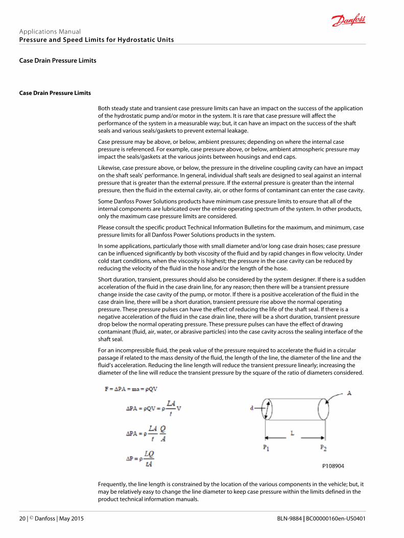
For an incompressible fluid, the peak value of the pressure required to accelerate the fluid in a circularpassage if related to the mass density of the fluid, the length of the line, the diameter of the line and thefluid’s acceleration. Reducing the line length will reduce the transient pressure linearly; increasing thediameter of the line will reduce the transient pressure by the square of the ratio of diameters considered.
Frequently, the line length is constrained by the location of the various components in the vehicle; but, itmay be relatively easy to change the line diameter to keep case pressure within the limits defined in theproduct technical information manuals.
Applications ManualPressure and Speed Limits for Hydrostatic Units
Case Drain Pressure Limits
20 | © Danfoss | May 2015 BLN-9884 | BC00000160en-US0401

Applications ManualPressure and Speed Limits for Hydrostatic Units
© Danfoss | May 2015 BLN-9884 | BC00000160en-US0401 | 21
Applications ManualPressure and Speed Limits for Hydrostatic Units
22 | © Danfoss | May 2015 BLN-9884 | BC00000160en-US0401
Applications ManualPressure and Speed Limits for Hydrostatic Units
© Danfoss | May 2015 BLN-9884 | BC00000160en-US0401 | 23

Danfoss Power Solutions is a global manufacturer and supplier of high-quality hydraulic andelectronic components. We specialize in providing state-of-the-art technology and solutionsthat excel in the harsh operating conditions of the mobile off-highway market. Building onour extensive applications expertise, we work closely with our customers to ensureexceptional performance for a broad range of off-highway vehicles.
We help OEMs around the world speed up system development, reduce costs and bringvehicles to market faster.
Danfoss – Your Strongest Partner in Mobile Hydraulics.
Go to www.powersolutions.danfoss.com for further product information.
Wherever off-highway vehicles are at work, so is Danfoss. We offer expert worldwide supportfor our customers, ensuring the best possible solutions for outstanding performance. Andwith an extensive network of Global Service Partners, we also provide comprehensive globalservice for all of our components.
Please contact the Danfoss Power Solution representative nearest you.
Local address:
Danfoss Power Solutions GmbH & Co. OHGKrokamp 35D-24539 Neumünster, GermanyPhone: +49 4321 871 0
Danfoss Power Solutions ApSNordborgvej 81DK-6430 Nordborg, DenmarkPhone: +45 7488 2222
Danfoss Power Solutions (US) Company2800 East 13th StreetAmes, IA 50010, USAPhone: +1 515 239 6000
Danfoss Power Solutions Trading(Shanghai) Co., Ltd.Building #22, No. 1000 Jin Hai RdJin Qiao, Pudong New DistrictShanghai, China 201206Phone: +86 21 3418 5200
Danfoss can accept no responsibility for possible errors in catalogues, brochures and other printed material. Danfoss reserves the right to alter its products without notice. This also applies to productsalready on order provided that such alterations can be made without changes being necessary in specifications already agreed.All trademarks in this material are property of the respective companies. Danfoss and the Danfoss logotype are trademarks of Danfoss A/S. All rights reserved.
© Danfoss | May 2015 BLN-9884 | BC00000160en-US0401
Products we offer:
• Bent Axis Motors
• Closed Circuit Axial PistonPumps and Motors
• Displays
• Electrohydraulic PowerSteering
• Electrohydraulics
• Hydraulic Power Steering
• Integrated Systems
• Joysticks and ControlHandles
• Microcontrollers andSoftware
• Open Circuit Axial PistonPumps
• Orbital Motors
• PLUS+1® GUIDE
• Proportional Valves
• Sensors
• Steering
• Transit Mixer Drives
Comatrolwww.comatrol.com
Turolla www.turollaocg.com
Hydro-Gearwww.hydro-gear.com
Daikin-Sauer-Danfosswww.daikin-sauer-danfoss.com