pressure balanced shower control
TRANSCRIPT
PRESSURE BALANCED
User Guide
Installation and
SHOWER CONTROL
THESE INSTRUCTIONS ARE TO BE LEFT WITH THE USER

2
p y
ContentsSection Page
1 ....... Introduction ................................................................... 3
2 ....... Important Safety Information ........................................... 4
3 ....... Pack Contents Checklist .................................................. 5
4 ....... Dimensions ................................................................... 7
5 ....... Specifications ................................................................... 8
6 ....... Installation Requirements ................................................ 9
7 ....... Installation ................................................................. 14
8 ....... Commissioning ............................................................... 29
9 ....... Operation ......................................................................... 33
10 ..... Fault Diagnosis ............................................................... 35
11 ..... Maintenance .................................................................... 41
12 ..... Spare Parts ...................................................................... 46
13 ..... Accessories .................................................................... 50
Guarantee, Customer Care Policy, and How to contact us ................................................................................................ Back cover

3
Thank you for purchasing a quality Mira product. To enjoy the full potential of your newproduct, please take time to read this guide thoroughly, having done so, keep it handy forfuture reference.
The Mira CombiForce 415 is a pressure balanced shower control which maintains aconstant outlet temperature irrespective of changes in inlet pressures as long as theinlet water temperatures remain the same. It is not a thermostatic shower control anddoes not sense supply temperature variations. Therefore, inlet water temperaturesespecially the hot, should remain relatively constant.
The Mira CombiForce 415 can be installed with the following packages:
- Fully modulating multipoint gas water heaters.- Fully modulating combination boilers.- Unvented mains pressure systems.- Mains pressurised, instantaneous hot water heated from thermal store, systems.- Pumped systems.
Showering temperature is adjusted by the shower control. The flow rate is determined bythe supply pressures available at the inlets, and the output rating of the heater appliance.
Shower controls covered by this guide:
Mira CombiForce 415
Surface mounted pressure balanced shower control for connection to exposed pipework,for high pressure applications (1.0 – 5.0 bar). Available in white/chrome, white/lightgolden or all chrome finish.
Mira CombiForce 415B
Built-in shower control for connection to concealed pipework, for high pressureapplications (1.0 – 5.0 bar). Available in white, white/chrome, white/light golden or allchrome finish.
1 IntroductionSection
If you experience any difficulty with the installation or operation of your newshower control, then please refer to Section 10, "Fault Diagnosis", beforecontacting Kohler Mira Limited. Our telephone and fax numbers can be found onthe back cover of this guide.

4
Important Safety Information1SectionSection
2 Important Safety Information
Warning!1. Products manufactured by us are safe and without risk provided they are
installed, used and maintained in good working order in accordance with ourinstructions and recommendations.
Caution!1. Read all of these instructions.
2. Retain this guide for later use.
3. Pass on this guide in the event of change of ownership of the installation site.
4. Follow all warnings, cautions and instructions contained in this guide.
5. The plumbing installation must comply with the requirements of UK WaterRegulations/Byelaws (Scotland), Building Regulations or any particularregulations and practices, specified by the local water supplier. Theinstallation should be carried out by a plumber or contractor who isregistered or is a member of an association such as:
- Institute of Plumbing (IOP), throughout the UK.
- National Association of Plumbing, Heating and Mechanical Services- Contractors (NAPH & MSC), England and Wales.
- Scottish and Northern Ireland Plumbing Employers’ Federation(SNIPEF), Scotland and Northern Ireland.
6. Anyone who may have difficulty understanding or operating the controls of anyshower should be attended whilst showering. Particular consideration shouldbe given to the young, the elderly, the infirm, or anyone inexperienced in thecorrect operation of the controls.

5
1 x CombiForce 415 Shower Control ❏ 2 x Pipe Concealing Plates ❏
2 x 1/2" BSP Inlet Connector Nipples ❏ 2 x Fibre Gaskets ❏ 2 x Olives ❏
2 x Compression Nuts ❏ 1 x Outlet Nipple ❏ 1 x 2.5 mm A/F
Hexagon Wrench ❏
2 x 13/4" Fixing Screws ❏ 2 x Wallplugs ❏ 1 x ‘O’ Seal ❏
❏ Tick the appropriate boxes to familiarise yourself with the part names and to confirmthat the parts are included.
1. Mira CombiForce 415 Surface Mounted Shower Control
3 Pack Contents ChecklistSection
✔
6
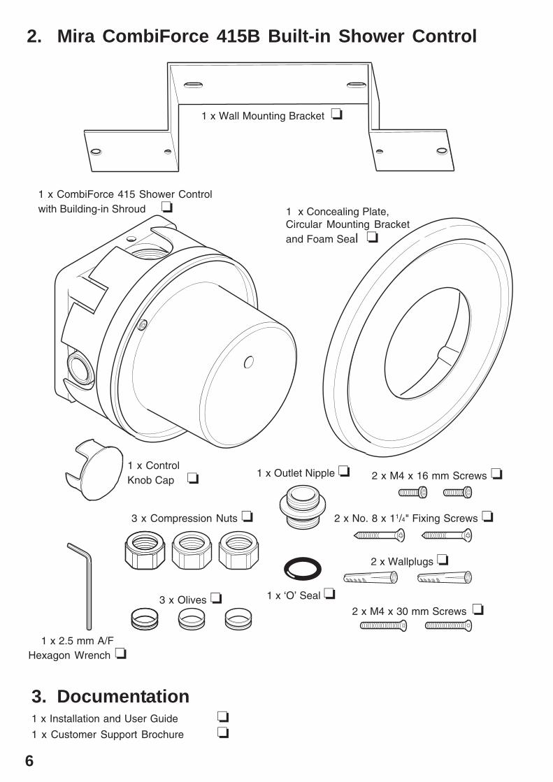
2. Mira CombiForce 415B Built-in Shower Control
3. Documentation1 x Installation and User Guide ❏1 x Customer Support Brochure ❏
1 x Wall Mounting Bracket ❏
1 x CombiForce 415 Shower Controlwith Building-in Shroud ❏ 1 x Concealing Plate,
Circular Mounting Bracketand Foam Seal ❏
3 x Compression Nuts ❏
3 x Olives ❏2 x M4 x 30 mm Screws ❏
2 x No. 8 x 11/4" Fixing Screws ❏
2 x Wallplugs ❏
2 x M4 x 16 mm Screws ❏
1 x 2.5 mm A/FHexagon Wrench ❏
1 x Outlet Nipple ❏
1 x ‘O’ Seal ❏
1 x ControlKnob Cap ❏
7
DimensionsSection4
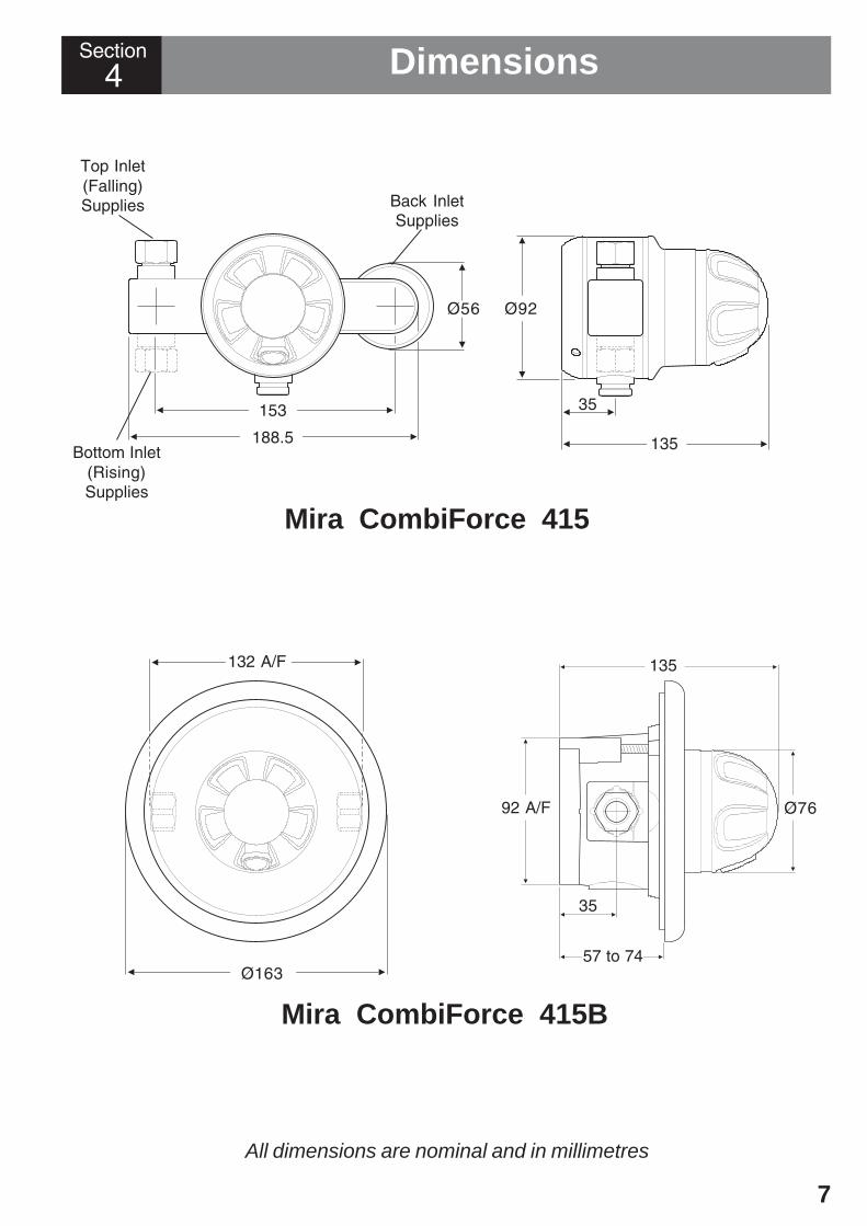
All dimensions are nominal and in millimetres
Mira CombiForce 415B
Mira CombiForce 415
Top Inlet(Falling)Supplies
Bottom Inlet(Rising)Supplies
153
Ø56
Back InletSupplies
Ø92
35
35
132 A/F 135
Ø163
188.5 135
92 A/F Ø76
57 to 74
8
SPECIFICATIONS5 SpecificationsSection
Mira CombiForce 415 and 415BPressure Range
Minimum maintained pressure: 1 bar.Maximum maintained pressure: 5 bar.Maximum static pressure: 10 bar.
Note! For optimum performance, the initial supply pressures should be nominallyequal.
TemperaturesHot and cold water supply temperatures MUST remain relatively constant.
Maximum hot water temperature: 85°C.
Ideally the hot water temperature should never exceed 65°C. A water temperature of60°C is considered sufficient to meet all normal requirements and will minimize thedeposition of scale in hard water areas.
ConnectionsInlet
15 mm Compression or 1/2'' BSP male (CombiForce 415).15 mm Compression (CombiForce 415B).
Outlet1/2'' BSP male (CombiForce 415).15 mm Compression or 1/2'' BSP male (CombiForce 415B).

9
Float operated valve
Stop or servicing valve
Shower control
Warning or overflow pipe
Drop tight pressure reducingvalve (PRV)
Key to symbols appearing throughout this guide.
1. Layout and sizing of pipework must be such that when other services are used,pressures at the shower control inlets do not fall below the recommended minimum(1 bar). The pressure balancing performance is impaired below 1 bar. When fittedwith some heater appliances the minimum maintained pressure may be above 1bar, refer to the section Commissioning: “Multipoint gas water heaters” or“Combination boilers”.
2. The Mira CombiForce 415 is not suitable for installation as part of a gravity-fedplumbing system (i.e. in conjunction with a hot water cylinder and cold waterstorage cistern), unless used in conjunction with an inlet pump producing amaintained pressure of at least 1 bar.
3. When used with a fully modulating multipoint or combination boiler above 5 barmaintained pressure, a pressure reducing valve will be necessary. For informationon measuring system pressures refer to Installation Requirements: "MeasuringSystem Pressures". For further information on pressure reducing valves consultyour local plumbing stockist.
4. Supply pipes MUST be flushed to clear debris before connecting the showercontrol.
5. Conveniently situated isolating valves MUST be fitted for servicing purposes.
6. If the shower control is to be used with a fully modulating multipoint waterheater, fully modulating combination boiler, thermal store or unvented systeman expansion vessel must be fitted to accommodate the expansion of water inthe domestic hot water supply (this may already be part of the system, checkthe details on the boiler/heater or contact the boiler/heater manufacturer).
7. No form of outlet flow control should be fitted, only Mira recommended fittingsshould be used in the outlet pipework.
6 Installation RequirementsSection
Twin impeller inlet pump
Tempering valve
Mini expansion vessel
Non-return Valve
10
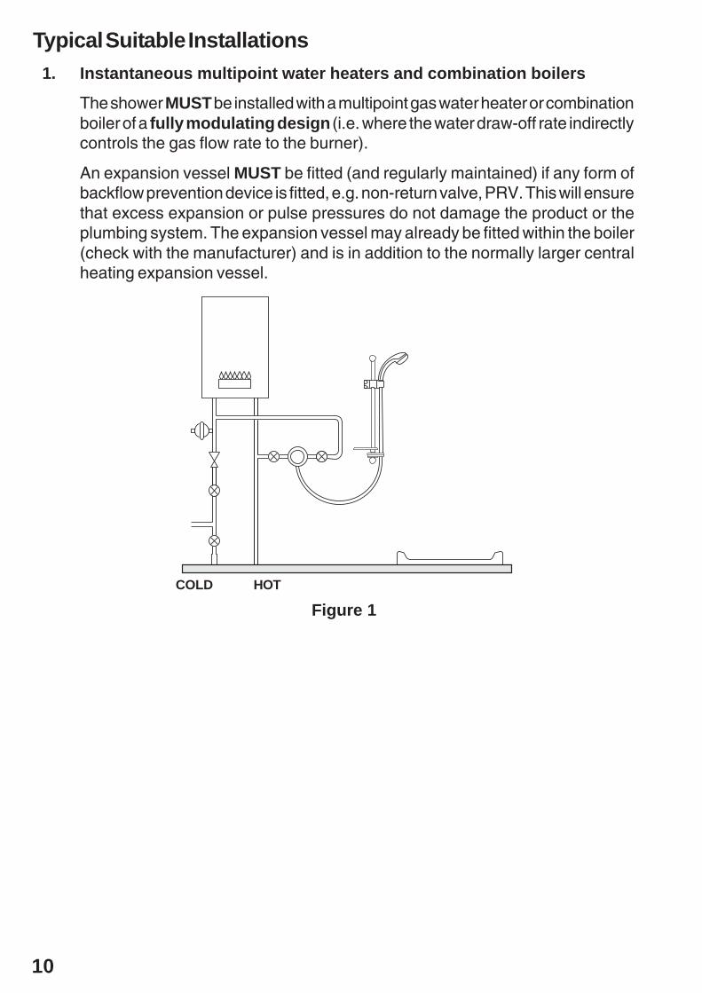
Typical Suitable Installations1. Instantaneous multipoint water heaters and combination boilers
The shower MUST be installed with a multipoint gas water heater or combinationboiler of a fully modulating design (i.e. where the water draw-off rate indirectlycontrols the gas flow rate to the burner).
An expansion vessel MUST be fitted (and regularly maintained) if any form ofbackflow prevention device is fitted, e.g. non-return valve, PRV. This will ensurethat excess expansion or pulse pressures do not damage the product or theplumbing system. The expansion vessel may already be fitted within the boiler(check with the manufacturer) and is in addition to the normally larger centralheating expansion vessel.
Figure 1HOTCOLD
11
HOTCOLD
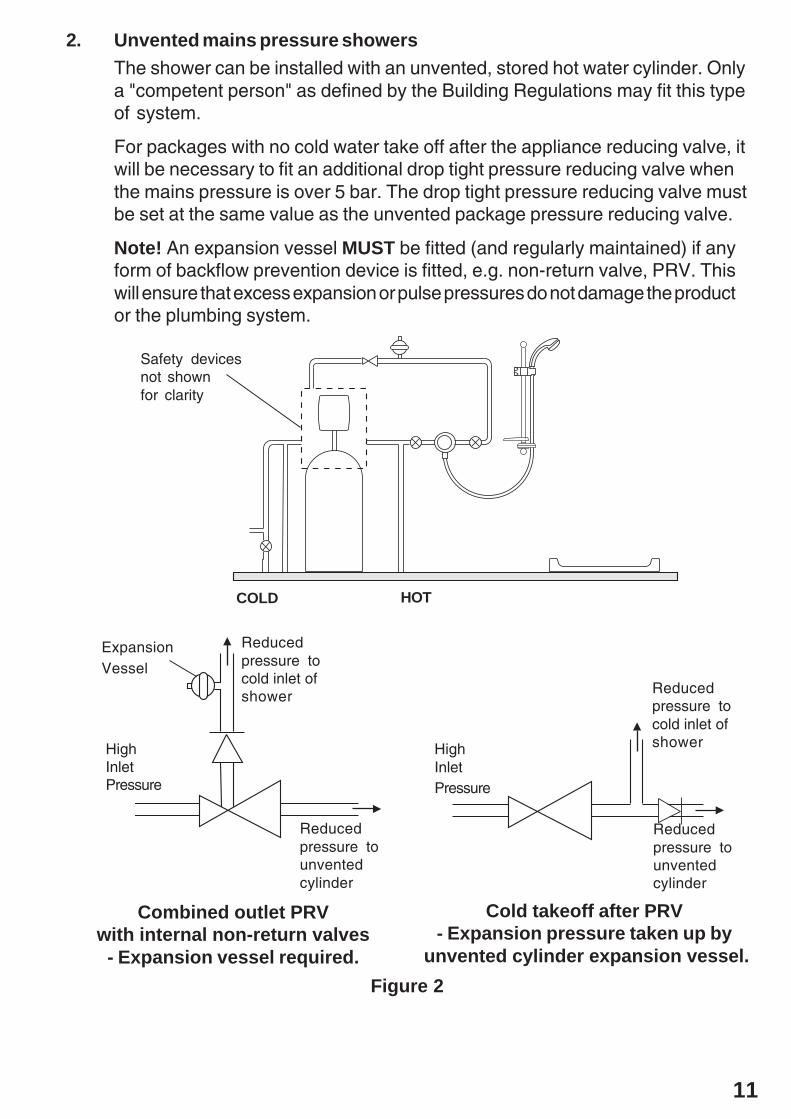
Combined outlet PRVwith internal non-return valves
- Expansion vessel required.
Cold takeoff after PRV- Expansion pressure taken up by
unvented cylinder expansion vessel.
Reducedpressure tounventedcylinder
HighInletPressure
Reducedpressure tocold inlet ofshower
Reducedpressure tounventedcylinder
HighInletPressure
Reducedpressure tocold inlet ofshower
ExpansionVessel
Safety devicesnot shownfor clarity
2. Unvented mains pressure showersThe shower can be installed with an unvented, stored hot water cylinder. Onlya "competent person" as defined by the Building Regulations may fit this typeof system.
For packages with no cold water take off after the appliance reducing valve, itwill be necessary to fit an additional drop tight pressure reducing valve whenthe mains pressure is over 5 bar. The drop tight pressure reducing valve mustbe set at the same value as the unvented package pressure reducing valve.
Note! An expansion vessel MUST be fitted (and regularly maintained) if anyform of backflow prevention device is fitted, e.g. non-return valve, PRV. Thiswill ensure that excess expansion or pulse pressures do not damage the productor the plumbing system.
Figure 2

12
3. Mains pressurised instantaneous hot water shower, heated from athermal storePackages of this type, fitted with a tempering valve can be used.
A drop tight pressure reducing valve MUST be fitted if the supply pressuresexceed 5 bar maintained.
An expansion vessel MUST be fitted (and regularly maintained) if any form ofbackflow prevention device is fitted, e.g. non-return valve, PRV. This willensure that excess expansion or pulse pressures do not damage the productor the plumbing system. The expansion vessel may already be fitted externallyor internally within the thermal store (check with thermal store manufacturer).
COLD HOT
Figure 3
4. Pumped showers (inlet pumps)The shower can be installed with an inlet pump (twin impeller). The pumpMUST be located on the floor next to the hot water cylinder. The hot watercylinder/vent pipes must be arranged as shown to achieve air separation.
90 °
30 to 60 °
Air Separation
Figure 4
13
Measuring System Pressures1. General
It is important that the system pressures are within the range specified for theMira CombiForce 415 (refer to the Specifications section).
If the system pressure is not known then the system pressure MUST bemeasured as explained in this section.
Pressures are those present at the inlet to the appliance either whilst running(maintained) or in the off state (static). Nearby hot and cold taps connected tothe same proposed feed pipes as the appliance can be used to measure thestatic pressure. No other fitting or appliance should be in use at this time.
Water pressures vary throughout the day, therefore you must ensure that waterpressures do not drop below or exceed the minimum/maximum required (referto the Specifications section).
2. To measure static pressure (Refer to Figure 5)
With the pressure testing device firmly connected to a tap drawing from one ofthe proposed feed pipes and the outlet from the device in the off position, thetap is turned on and the static pressure noted.
3. To measure maintained pressure (Refer to Figure 5)
The pressure testing device is connected as above, the taps turned on and theoutlet from the device opened until a flow of around 5 l/min is obtained (this iseasily done by timing the flow into a calibrated container). The maintainedpressure which can be expected when the shower is in operation can then beread. This should be carried out on the hot and cold supply.
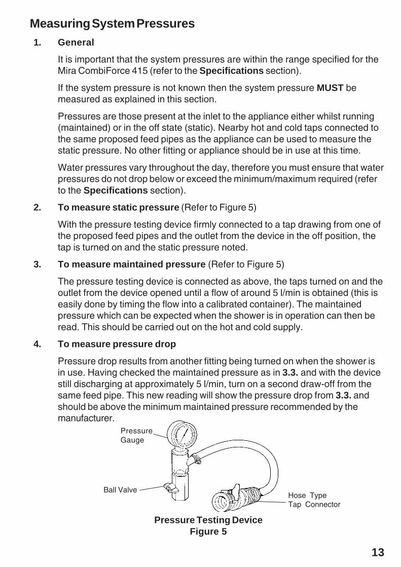
4. To measure pressure drop
Pressure drop results from another fitting being turned on when the shower isin use. Having checked the maintained pressure as in 3.3. and with the devicestill discharging at approximately 5 l/min, turn on a second draw-off from thesame feed pipe. This new reading will show the pressure drop from 3.3. andshould be above the minimum maintained pressure recommended by themanufacturer.
PressureGauge
Hose TypeTap Connector
Ball Valve
Pressure Testing DeviceFigure 5

14
1. Before you decide on the final positionof your shower control, please bear inmind the following:
- Decide on a suitable position forthe shower control. The positionof the shower control and theshower fittings must provide aminimum gap of 25 mm betweenthe spill-over level of the showertray/bath and the handset. Thisis to prevent backsiphonage.
- Determine whether the hot orcold water services will beconnected to the shower controlfrom the bottom (rising) or fromthe top (falling).
7 InstallationSection
Falling Supplies
Rising Supplies
25 mmMinimum
Spill-over Level
Hose RetainingRing
Mira CombiForce 415 Surface Mounted Shower Control
Rising or Falling Inlet SuppliesNote! The Mira CombiForce 415 is supplied with inlet connections hot left, cold rightand bottom outlet as standard. For installations with reversed hot and cold suppliescomplete the installation and refer to the section Installation: "Reversed InletSupplies".
15
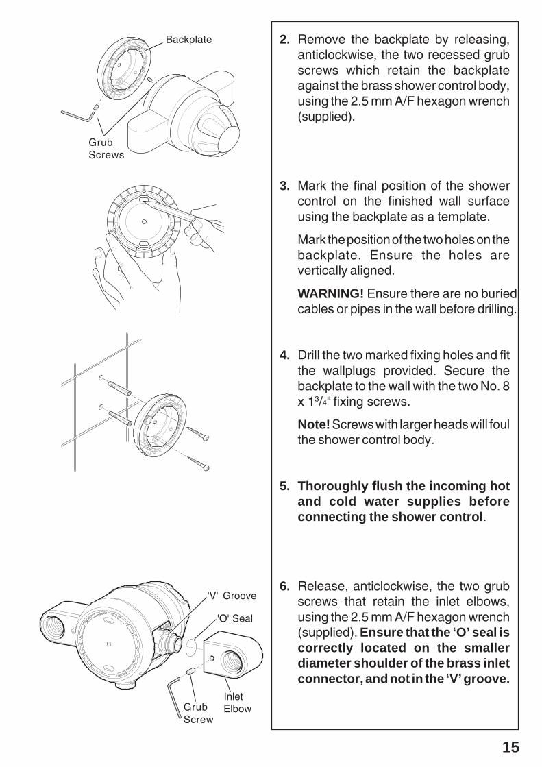
Backplate
GrubScrews
2. Remove the backplate by releasing,anticlockwise, the two recessed grubscrews which retain the backplateagainst the brass shower control body,using the 2.5 mm A/F hexagon wrench(supplied).
3. Mark the final position of the showercontrol on the finished wall surfaceusing the backplate as a template.
Mark the position of the two holes on thebackplate. Ensure the holes arevertically aligned.
WARNING! Ensure there are no buriedcables or pipes in the wall before drilling.
4. Drill the two marked fixing holes and fitthe wallplugs provided. Secure thebackplate to the wall with the two No. 8x 13/4" fixing screws.
Note! Screws with larger heads will foulthe shower control body.
5. Thoroughly flush the incoming hotand cold water supplies beforeconnecting the shower control.
6. Release, anticlockwise, the two grubscrews that retain the inlet elbows,using the 2.5 mm A/F hexagon wrench(supplied). Ensure that the ‘O’ seal iscorrectly located on the smallerdiameter shoulder of the brass inletconnector, and not in the ‘V’ groove.
'V' Groove
'O' Seal
InletElbowGrub
Screw

16
7. Fit the shower control body onto thebackplate and secure by tightening,clockwise, the two recessed grubscrews, using the 2.5 mm A/F hexagonwrench (supplied).
8. Refit the elbows in the required position,i.e. rising or falling supplies. Ensure thegrub screws locate into the 'V' grooveand tighten the grub screws.
9. Assemble the components of the inletconnector compression fittings in thefollowing sequence for each inlet:-
9.1. Place the fibre gasket againstthe shoulder of the 1/2" BSPinlet connector nipple.
9.2. Screw, clockwise, the 1/2"BSP connector nipple intothe elbow ensuring that thecompression taper facesuppermost, using a 12 mm A/Fhexagon wrench (not supplied).
Rising Supplies
Falling Supplies
ConnectorNipple
FibreGasket
Fibre Gasket15 mm Compression
1/2" Male BSP
Backplate
Shower Control Body
Grub Screws
17
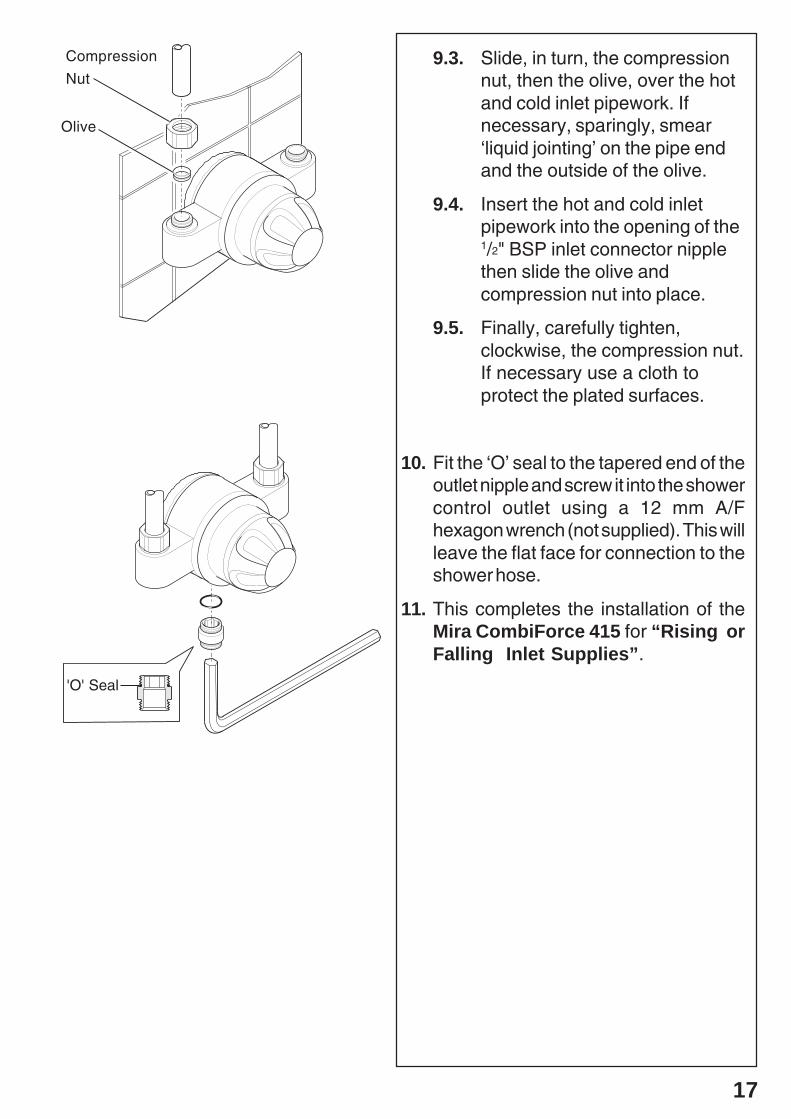
9.3. Slide, in turn, the compressionnut, then the olive, over the hotand cold inlet pipework. Ifnecessary, sparingly, smear‘liquid jointing’ on the pipe endand the outside of the olive.
9.4. Insert the hot and cold inletpipework into the opening of the1/2" BSP inlet connector nipplethen slide the olive andcompression nut into place.
9.5. Finally, carefully tighten,clockwise, the compression nut.If necessary use a cloth toprotect the plated surfaces.
10. Fit the ‘O’ seal to the tapered end of theoutlet nipple and screw it into the showercontrol outlet using a 12 mm A/Fhexagon wrench (not supplied). This willleave the flat face for connection to theshower hose.
11. This completes the installation of theMira CombiForce 415 for “Rising orFalling Inlet Supplies”.
'O' Seal
Compression
Nut
Olive

18
Back Inlet Supplies
1. Follow the shower control installationprocedure as for “Rising or FallingInlet Supplies”: instructions 1. to 4.inclusive.
2. Using a spirit level, mark the route ofincoming hot and cold water supplypipes at a distance of 153 mm centres.
3. Remove the plaster and brickwork to therequired depth to conceal the supplypipework.
Note! Depth must be sufficient to preventpipe concealing plates fouling on theplumbing elbows.
4. Install the hot and cold water supplypipework ensuring that the pipe endsemerge from the wall surface at 153 mmcentres, and project from the finishedwall surface by 13 mm. Allow for twocircular recesses measuring 32 mmdiameter x 10 mm depth, to accept thetwo pipework concealing plates.
5. Make good the wall surface.
Fit the pipework concealing plates overhot and cold water supply pipework.
Backplate
ConcealingPlate
32 mm
13 mm fromfinished wallsurface
10 mm minimumbetween elbowand finished wallsurface.
153 mm
CircularRecess
Elbow

19
FibreGasket
6. Fit the gaskets to the 1/2" BSP connectornipples and screw in the nipples with thetapered ends outermost to accept thecompression fittings. Tighten the 1/2"BSP connector nipples fully with a12 mm A/F hexagon wrench (notsupplied).
7. Thoroughly flush the incoming hotand cold water supply pipes beforeconnecting the shower control. Failureto do so may result in productmalfunction.
8. Slip the compression nuts and olivesover the supply pipes.
9. Locate the shower control body onto thebackplate and inlet supply pipework,then secure by tightening, clockwise,the two recessed grub screws, using the2.5 mm A/F hexagon wrench (supplied).
Tighten the compression nuts, using ifnecessary, a cloth to protect the platedsurfaces.
Turn on the water supplies and checkfor any leaks!
10. Fit the ‘O’ seal to the tapered end of theoutlet nipple and screw it into the showercontrol outlet using a 12 mm A/F hexagonwrench (not supplied). This will leave theflat face for connection to the showerhose.
11. This completes the installation of theMira CombiForce 415 for “Back InletSupplies”.
Connector Nipple
FibreGasket
Connector Nipple
'O' Seal
15 mmCompression
1/2" MaleBSP
'O' Seal
20
Mira CombiForce 415B Built-in Shower Control
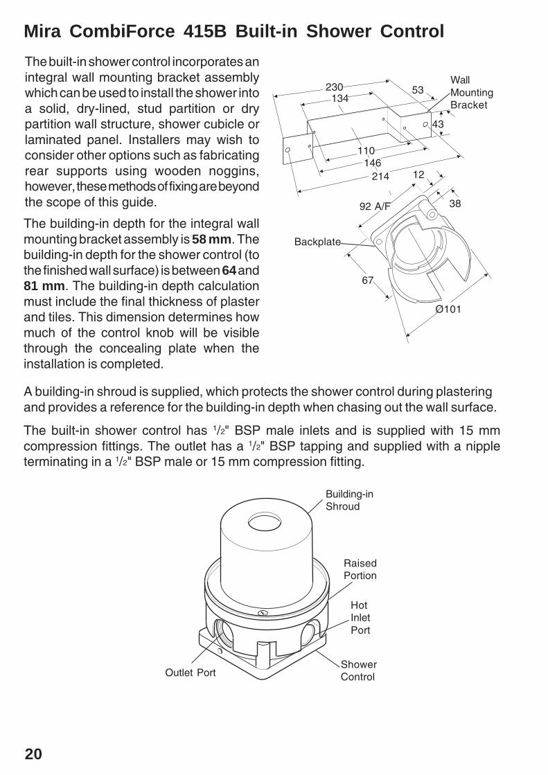
The building-in depth for the integral wallmounting bracket assembly is 58 mm. Thebuilding-in depth for the shower control (tothe finished wall surface) is between 64 and81 mm. The building-in depth calculationmust include the final thickness of plasterand tiles. This dimension determines howmuch of the control knob will be visiblethrough the concealing plate when theinstallation is completed.
Outlet Port
HotInletPort
ShowerControl
Building-inShroud
RaisedPortion
The built-in shower control incorporates anintegral wall mounting bracket assemblywhich can be used to install the shower intoa solid, dry-lined, stud partition or drypartition wall structure, shower cubicle orlaminated panel. Installers may wish toconsider other options such as fabricatingrear supports using wooden noggins,however, these methods of fixing are beyondthe scope of this guide.
A building-in shroud is supplied, which protects the shower control during plasteringand provides a reference for the building-in depth when chasing out the wall surface.
The built-in shower control has 1/2" BSP male inlets and is supplied with 15 mmcompression fittings. The outlet has a 1/2" BSP tapping and supplied with a nippleterminating in a 1/2" BSP male or 15 mm compression fitting.
230134
110146
214
53
43
67
92 A/F
12
38
WallMountingBracket
Backplate
Ø101
21
Solid, Dry-lined, Stud Partition or Dry Partition Wall Structures
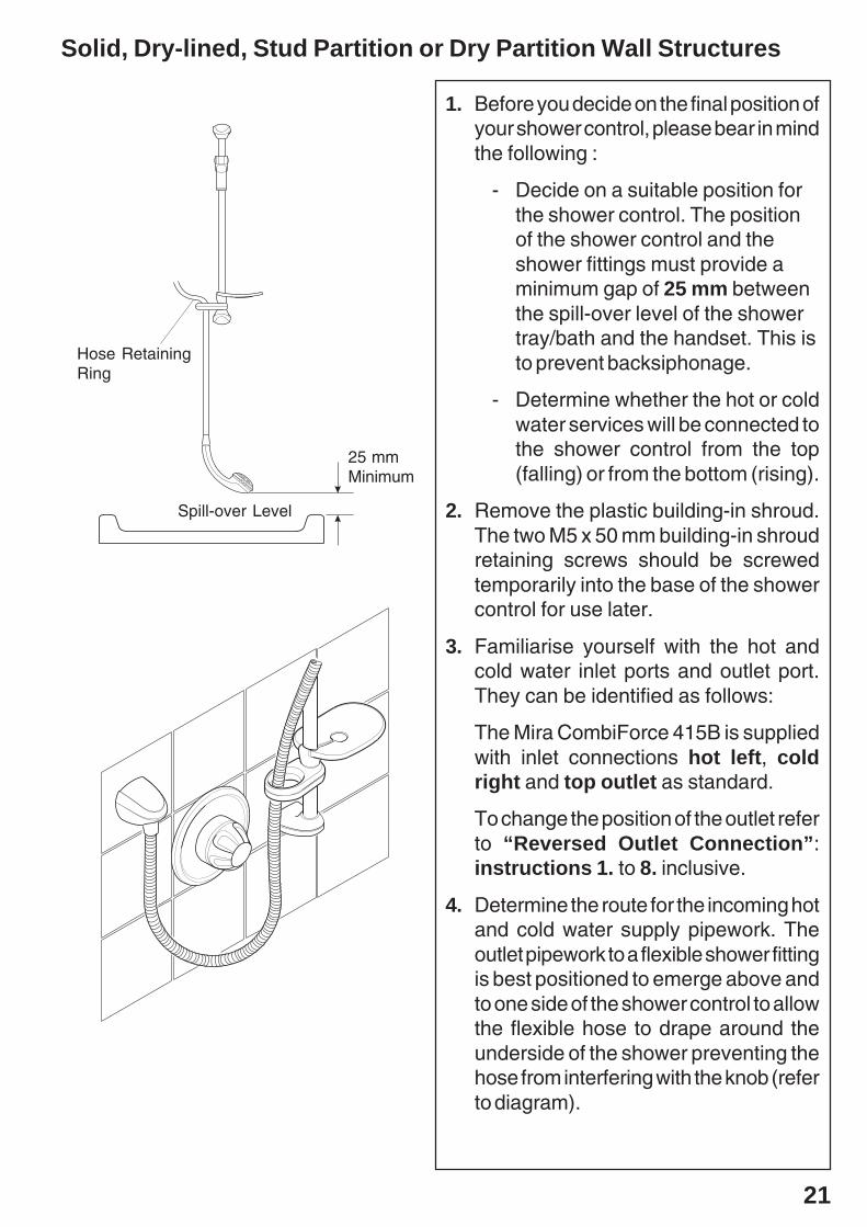
1. Before you decide on the final position ofyour shower control, please bear in mindthe following :
- Decide on a suitable position forthe shower control. The positionof the shower control and theshower fittings must provide aminimum gap of 25 mm betweenthe spill-over level of the showertray/bath and the handset. This isto prevent backsiphonage.
- Determine whether the hot or coldwater services will be connected tothe shower control from the top(falling) or from the bottom (rising).
2. Remove the plastic building-in shroud.The two M5 x 50 mm building-in shroudretaining screws should be screwedtemporarily into the base of the showercontrol for use later.
3. Familiarise yourself with the hot andcold water inlet ports and outlet port.They can be identified as follows:
The Mira CombiForce 415B is suppliedwith inlet connections hot left, coldright and top outlet as standard.
To change the position of the outlet referto “Reversed Outlet Connection”:instructions 1. to 8. inclusive.
4. Determine the route for the incoming hotand cold water supply pipework. Theoutlet pipework to a flexible shower fittingis best positioned to emerge above andto one side of the shower control to allowthe flexible hose to drape around theunderside of the shower preventing thehose from interfering with the knob (referto diagram).
25 mmMinimum
Spill-over Level
Hose RetainingRing

22
5. Mark the wall surface for an openingmeasuring approximately 245 mm x125 mm.
Mark the route of the incoming andoutgoing pipework services.
Using the building-in shroud as a guideremove the plaster and brickwork/dry-lining to the required depth ofconcealment.
Note! The depth of concealment mustbe such that the final wall surface (e.g.plaster and tiles etc.) finishes on theraised portion of the plastic building-inshroud.
6. Mark the final position on the wall of thetwo larger outer diameter fixing holes inthe flanges of the wall mounting bracket.This bracket must be fixed at 45°.
7. Drill and suitably plug the two markedfixing holes.
8. Thoroughly flush the incoming hotand cold water supply pipes beforeconnecting the shower control.
9. Fix the shower control to the wallmounting bracket using the two M4 x 16mm screws provided.
10. Install the shower control aligning thetwo flange holes of the wall mountingbracket assembly with the pre-drilledfixing holes.
Secure the shower control with the twoNo. 8 x 11/4" fixing screws supplied.
Shower Control
Wall MountingBracket
125 mm
245 mm

23
11. Connect the incoming hot and cold watersupply pipes :
11.1 Slide the compression nut, thenthe olive, over the pipe end. Ifnecessary, sparingly smearliquid jointing on the pipe endand the outside of the olive.
11.2 Insert the pipe end into theopening of the inlet connectorthen slide the olive andcompression nut into place.
11.3 Finally, carefully tighten,clockwise, the compressionnuts.
12. Connect the outlet pipe :
12.1 Place the ‘O’ seal on to thenipple, as shown. Locate thehexagon towards the showercontrol outlet port. Screw thenipple, clockwise, into the outletport using a 12 mm A/Fhexagon wrench (not supplied).
12.2 Slide the compression nut, thenthe olive, over the pipe end. Ifnecessary, sparingly, smearliquid jointing on the pipe end.
12.3 Insert pipe end into the openingof the outlet nipple then slidethe olive and compression nutinto place.
12.4 Finally, carefully tighten,clockwise, the components.
Turn on the water supplies and checkthe pipework for any leaks!
13. Refit the plastic building-in shroud overthe shower control and secure with thetwo M5 x 50 mm shroud retaining screws,removed in instruction 2.
'O' Seal
OutletNipple
24
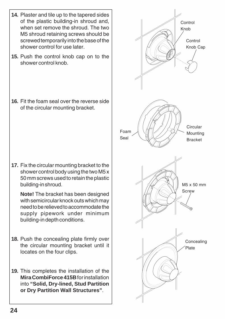
14. Plaster and tile up to the tapered sidesof the plastic building-in shroud and,when set remove the shroud. The twoM5 shroud retaining screws should bescrewed temporarily into the base of theshower control for use later.
15. Push the control knob cap on to theshower control knob.
16. Fit the foam seal over the reverse sideof the circular mounting bracket.
17. Fix the circular mounting bracket to theshower control body using the two M5 x50 mm screws used to retain the plasticbuilding-in shroud.
Note! The bracket has been designedwith semicircular knock outs which mayneed to be relieved to accommodate thesupply pipework under minimumbuilding-in depth conditions.
18. Push the concealing plate firmly overthe circular mounting bracket until itlocates on the four clips.
19. This completes the installation of theMira CombiForce 415B for installationinto “Solid, Dry-lined, Stud Partitionor Dry Partition Wall Structures”.
Foam
Seal
Circular
Mounting
Bracket
M5 x 50 mm
Screw
Concealing
Plate
Control
Knob Cap
Control
Knob

25
Shower Cubicle or Laminated PanelThe built-in shower control incorporates an integral wall mounting bracket assemblywhich can be used to install the shower into the front or back face of a shower cubicleor laminated panel.
Installation on to the Front Face of a Shower Cubicle or LaminatedPanelDepending on the structure of the shower cubicle or laminated panel it may be possibleto conceal the flanges of the integral wall mounting bracket assembly into the front faceof the wall surface then cover over the fixings with plaster and tiles. The building-in depthfor the integral wall mounting bracket assembly is 58 mm. The thickness of plaster andtiles which conceal the integral wall mounting bracket assembly flanges must be between6 and 23 mm.
230134
110146
214
53
43
67
92 A/F
1238
WallMountingBracket
Backplate
Ø101
1. Follow the shower control installationprocedure as for “Solid, Dry-lined,Stud partition or Dry Partition WallStructures”: instructions 1. to 4.inclusive.
2. Cut a circular hole in the panel measuring145 mm in diameter.
3. Follow the shower control installationprocedure as for “Solid, Dry-lined,Stud Partition or Dry Partition WallStructures”: instructions 6. to 18.inclusive to complete the installation.
26
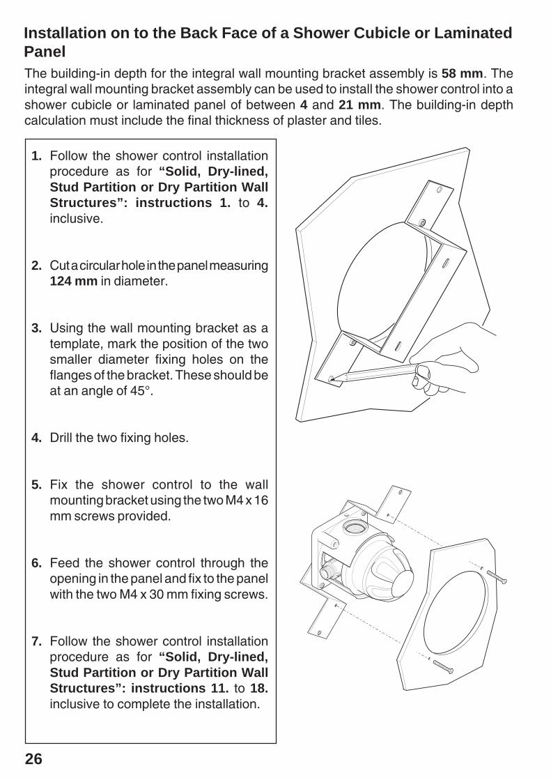
Installation on to the Back Face of a Shower Cubicle or LaminatedPanelThe building-in depth for the integral wall mounting bracket assembly is 58 mm. Theintegral wall mounting bracket assembly can be used to install the shower control into ashower cubicle or laminated panel of between 4 and 21 mm. The building-in depthcalculation must include the final thickness of plaster and tiles.
1. Follow the shower control installationprocedure as for “Solid, Dry-lined,Stud Partition or Dry Partition WallStructures”: instructions 1. to 4.inclusive.
2. Cut a circular hole in the panel measuring124 mm in diameter.
3. Using the wall mounting bracket as atemplate, mark the position of the twosmaller diameter fixing holes on theflanges of the bracket. These should beat an angle of 45°.
4. Drill the two fixing holes.
5. Fix the shower control to the wallmounting bracket using the two M4 x 16mm screws provided.
6. Feed the shower control through theopening in the panel and fix to the panelwith the two M4 x 30 mm fixing screws.
7. Follow the shower control installationprocedure as for “Solid, Dry-lined,Stud Partition or Dry Partition WallStructures”: instructions 11. to 18.inclusive to complete the installation.

27
Reversed Outlet ConnectionMira CombiForce 415 shower controls are supplied with inlet connections hot left, coldright and bottom outlet. The Mira CombiForce 415B is supplied with inlet connectionshot left, cold right and top outlet as standard.
To reverse the outlet position:
1. Rotate the shower control body through 180o and install the shower control.
2. Prise off the concealing cap, unscrew the control knob retaining screw and removethe temperature override stop and control knob.
3. Remove the D-shaped hub fitted to the spindle. Rotate the spindle one full turn (360o)and refit the hub.
4. Remove the adjustable temperature stop and turn over. Make sure that the Max oCwith the indentations side is uppermost. Adjust the maximum temperature stop(refer to Commissioning).
5. Refit the control knob assembly (with the override button at the bottom) and turn theknob fully clockwise to the shut off position.
6. This completes the procedure for “Reversed Outlet Connection”.
Cover Shroud
Cover ShroudRetaining Screws
ConcealingCap
AdjustableTemperature Stop
Hub
Control Knob
PlasticOverrideStop
Control KnobRetaining Screw
The hub is 'D' shaped. Thisensures the hub is fitted in thecorrect position.
Spindle
Skid Washer

28
Reversed Inlet SuppliesMira CombiForce 415 shower controls are supplied with inlet connections hot left, coldright and bottom outlet. The Mira CombiForce 415B is supplied with inlet connectionshot left, cold right and top outlet as standard.
Both shower controls are fitted with a single sequential control knob.
The shower control is turned off by turning the control knob fully clockwise. The correctsequence of operation is anticlockwise movement of the control knob followed by: Cold
Warm Hot water. If the sequence is: Hot Warm Cold water, then the hot andcold water supplies have been reversed.
To correct reversed hot and cold inlet supplies proceed as follows:
1. Prise off the concealing cap, remove the control knob retaining screw/plastictemperature override stop and the control knob.
2. Remove the hub. Turn the spindle one full turn (360o). Refit the hub.
3. Refit the control knob, (with the override button at the bottom), the control knobretaining screw/plastic override stop and the concealing cap.
4. Check the maximum temperature. Adjust if necessary (refer to Commissioning).
5. Turn the knob fully clockwise to the shut off position.
6. This completes the procedure for "Reversed Inlet Supplies".
Control Knob
Hub
Plastic OverrideStop
Concealing Cap
Control KnobRetaining Screw
Skid Washer

29
All heater appliances must have a fully modulating heat output for the domestichot water, to provide a constant temperature of hot water to the Mira CombiForce 415shower control.
Multipoint Gas Water HeatersThese notes are based on a heater with an effective output power of 23.5 kW. Heaters withhigher or lower effective output powers will proportionally affect the following information.
The Mira CombiForce 415 range does not compensate for water temperaturechanges.
1. Use the heater appliance on a “high” or “winter” setting only.
2. A minimum maintained water supply pressure of 1.5 bar is required to the waterheater. This allows for a 0.5 bar pressure loss in the heater and ensures themaintained inlet pressure at the shower is above 1 bar.
3. The maintained water supply pressure should not exceed 5 bar. A pressure reducingvalve will be needed for pressures over 5 bar to improve the system operation. Itshould be installed to reduce both the cold feed pressure to the heater and the coldfeed pressure to the Mira CombiForce 415 to approximately 3.5 bar.
Additional benefits may be obtained by fitting the pressure reducing valve after thepremises internal stop valve, drain valve and if fitted, outside tap. The valve shouldbe correctly sized for the duty.
4. If the minimum modulating output of the heater appliance exceeds 14 kW with areducing hot flow rate, then the maintained minimum supply pressure will need tobe increased. This is to keep the flow rate through the heater sufficiently high in orderto ensure that the gas flame stays ignited. An extinguished flame will produce a coldshower after a short period of time.
Combination Boilers1. This information is based on a heater appliance fitted with an internal flow regulator
rated at 10 l/min hot water.
2. Use the heater appliance on a “high” or “winter” setting only.
3. Should it not be possible to get a hot enough shower it may be necessary to fit a9 l/min flow regulator (available from Kohler Mira Customer Services) between theshower control and hose to further reduce the flow. The “top hat” regulator shouldfit into the hose recess such that the black ‘O’ seal is visible before attaching thehose to the shower control.
4. A minimum maintained water supply pressure of 1.5 bar is required. This allows fora 0.5 bar pressure loss in the heater.
8 CommissioningSection

30
5. The maintained water supply pressure should not exceed 5 bar. A pressure reducingvalve will be needed for pressures over 5 bar to improve the system operation. Itshould be installed to reduce both the cold feed pressure to the heater applianceand the cold feed pressure to the Mira CombiForce 415 to approximately 3.5 bar.
Additional benefits may be obtained by fitting the water pressure reducing valveafter the premises internal stop valve, drain valve and if fitted, outside tap. Thevalve should be correctly sized for the duty.
6. The minimum maintained water supply pressure will need to be raised if theminimum heater output power is greater than 7.5 kW on a reducing flow with a hottemperature of 62.5°C.
Adjustable Maximum Temperature SettingMira CombiForce 415 shower controls are fully performance tested. The adjustablemaximum temperature (maximum angular movement prior to override) has been presetunder ideal installation conditions at the factory. Site conditions and personal preferencemay dictate that the maximum temperature needs to be reset.
To reset the adjustable maximum temperature stop ensure that an adequate supply of hotwater is available in excess of that required from the shower control. Turn the control knobfully anticlockwise. Check the temperature at the discharge point (allow hot water to reachthe shower). If incorrect, adjust the temperature as follows:
1. Turn the control knob anticlockwise until the desired maximum temperature isachieved. It may be necessary to press the override button and continue to rotateanticlockwise, past the preset maximum temperature setting. Note the finalposition of the button, e.g. 11 O ’clock.
2. Turn the control knob fully off.
3. Remove the concealing cap.
4. Remove the control knob retaining screw/plastic temperature override stop and pulloff the control knob.
5. Locate the adjustable temperature stop (identified by a part number and a “MAX °C”symbol or a “MAX °C” symbol and component indentations).
Note! Ensure that the original face identified, is uppermost after adjustment.
6. With reference to the diagrams, carefully remove the adjustable temperature stop.Reposition the stop so that the “MAX °C” symbol is aligned with the noted buttonposition, e.g. 11 O’ clock.
7. To check the desired maximum temperature setting has been correctly set, refit thehub and control knob, turn fully anticlockwise and check the temperature of thewater at the outlet. If still incorrect:
To increase the temperature, reposition the stop one serration anticlockwise.

31
8. Refit the control knob (with the override button at the bottom), control knob retainingscrew/plastic override stop and concealing cap.Please ensure the plastic overridestop is correctly seated.
Note! Do not overtighten the control knob retaining screw. Internal components maybe damaged if the screw is overtightened.
9. This completes the procedure for Commissioning: "Adjustable MaximumTemperature Setting”.
ConcealingCap
Control Knob
PlasticOverrideStop
Control KnobRetaining Screw
AdjustableTemperatureStopTemperature
Override Button
To decrease the temperature, reposition the stop one serration clockwise.
Repeat the check as necessary.
Indentations
AdjustableTemperatureStop

32
Temperature Override Button DisableThe Mira CombiForce 415 incorporates a safety feature which prevents thetemperature override button from being depressed, enabling the user to access ahigher shower temperature. The shower control is despatched from the factory withthe button in the “enabled” position.The following sequence will allow the installer to “disable” the temperature overridebutton if required.
1. Ensure the shower control is turned off.
Remove the concealing cap.
2. Locate the plastic temperature override stop.
3. Pull out the temperature override stop and reposition it in the slot adjacent to thered temperature override button.
4. Reversing the above procedure will “enable” the temperature override buttonmovement.
TemperatureOverride Button
TemperatureOverride Stop
Temperature OverrideButton Enabled
Temperature OverrideButton Disabled
33
=
=
=
MAX. Cº
+
+
+
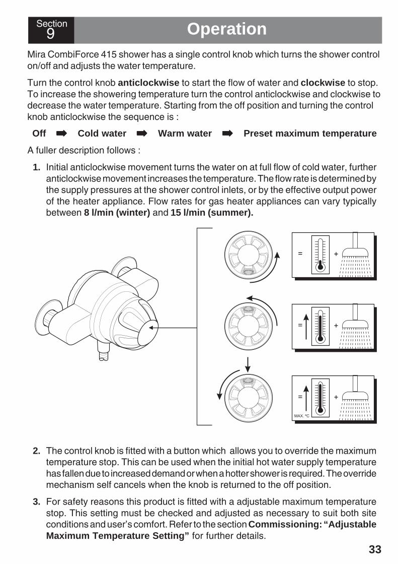
Mira CombiForce 415 shower has a single control knob which turns the shower controlon/off and adjusts the water temperature.
Turn the control knob anticlockwise to start the flow of water and clockwise to stop.To increase the showering temperature turn the control anticlockwise and clockwise todecrease the water temperature. Starting from the off position and turning the controlknob anticlockwise the sequence is :
Off ➡➡➡➡➡ Cold water ➡➡➡➡➡ Warm water ➡➡➡➡➡ Preset maximum temperature
A fuller description follows :
1. Initial anticlockwise movement turns the water on at full flow of cold water, furtheranticlockwise movement increases the temperature. The flow rate is determined bythe supply pressures at the shower control inlets, or by the effective output powerof the heater appliance. Flow rates for gas heater appliances can vary typicallybetween 8 l/min (winter) and 15 l/min (summer).
2. The control knob is fitted with a button which allows you to override the maximumtemperature stop. This can be used when the initial hot water supply temperaturehas fallen due to increased demand or when a hotter shower is required. The overridemechanism self cancels when the knob is returned to the off position.
3. For safety reasons this product is fitted with a adjustable maximum temperaturestop. This setting must be checked and adjusted as necessary to suit both siteconditions and user’s comfort. Refer to the section Commissioning: “AdjustableMaximum Temperature Setting” for further details.
9 OperationSection
34
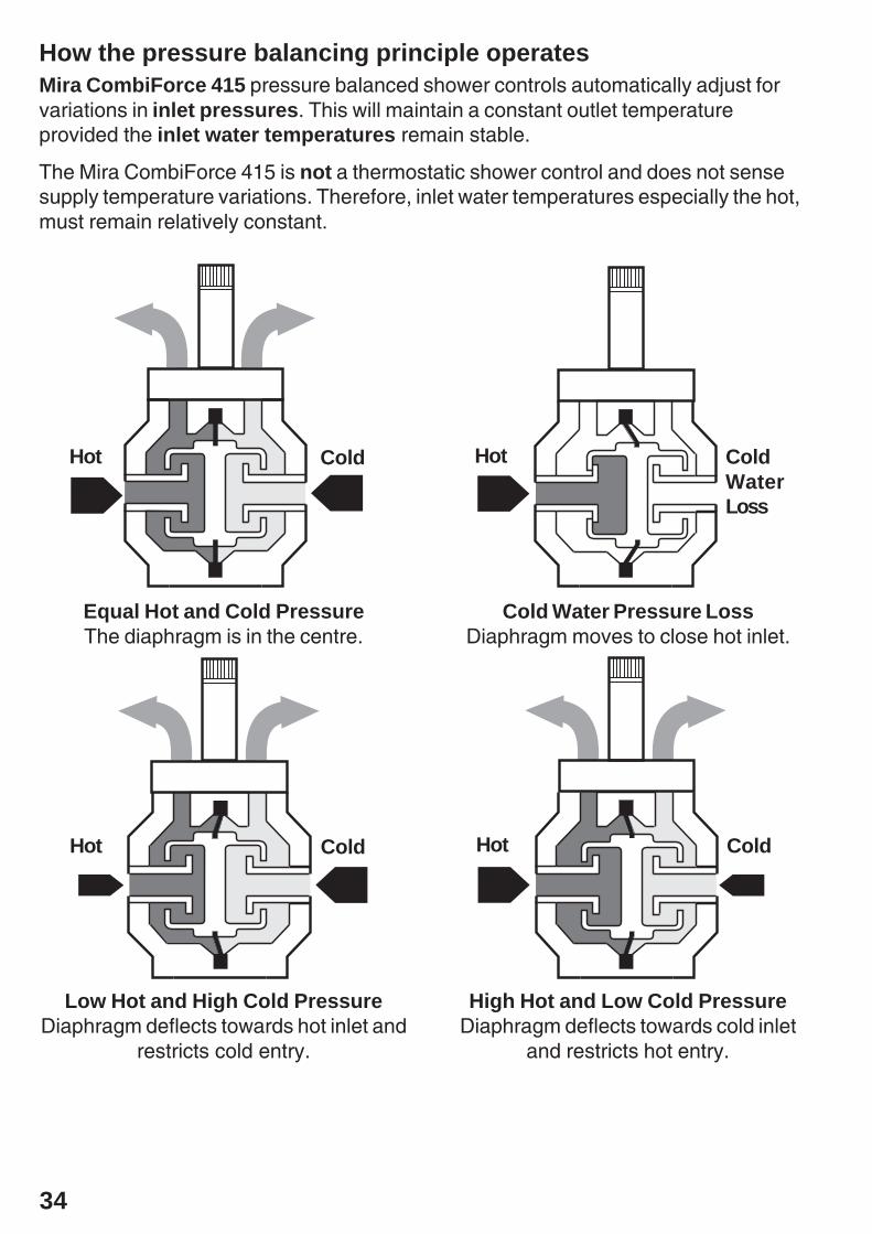
How the pressure balancing principle operatesMira CombiForce 415 pressure balanced shower controls automatically adjust forvariations in inlet pressures. This will maintain a constant outlet temperatureprovided the inlet water temperatures remain stable.
The Mira CombiForce 415 is not a thermostatic shower control and does not sensesupply temperature variations. Therefore, inlet water temperatures especially the hot,must remain relatively constant.
Equal Hot and Cold PressureThe diaphragm is in the centre.
Low Hot and High Cold PressureDiaphragm deflects towards hot inlet and
restricts cold entry.
Cold Water Pressure LossDiaphragm moves to close hot inlet.
High Hot and Low Cold PressureDiaphragm deflects towards cold inlet
and restricts hot entry.
Hot Cold
Hot Cold Hot Cold
Hot ColdWaterLoss

35
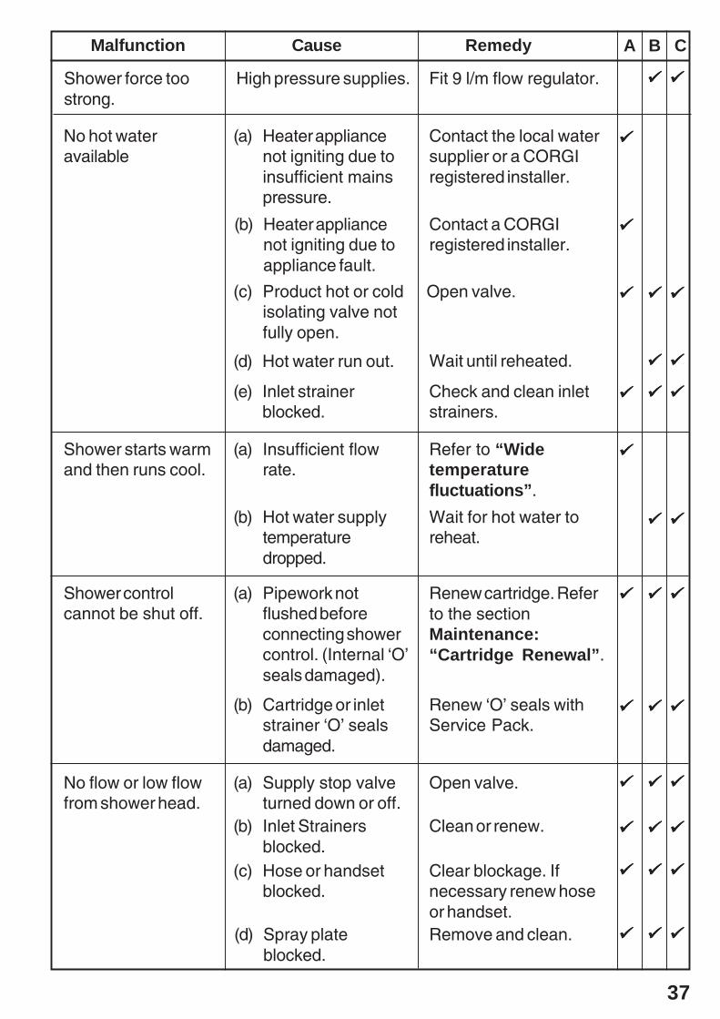
Customer Fault DiagnosisThe trouble shooting information tabled below gives details on what you can do as auser should you encounter difficulties whilst operating the shower.
Note! Should these remedies prove to be unsuccessful in solving your problem, contactyour installer for further advice.
Key for applicability columnA - Instantaneous gas heated showers.B - Unvented mains pressure showers.C - Mains pressurised, instantaneous hot water, heated from thermal store showers.
Section
10 Fault Diagnosis
Showerinsufficiently hot.
Wide temperaturefluctuations fromshower when noother draw-off isbeing made.
(a) Maximumtemperatureincorrectly set.
Reset adjustablemaximumtemperature.
(b) Heater not set onmaximum hot.
(c) Flow rate still toohigh.
Consult heaterinstructions or contact aCORGI registeredinstaller.
Fit 9 l/min flow regulatorbetween shower controland hose.
Contact your local watersupplier or a CORGIregistered installer.
(d) See also“Showerinsufficientlyhot”.
RemedyMalfunction Cause A B C
Check and clean inletstrainers.
(a) Insufficient flowrate causing theheater to cycle onand off.
(b) Insufficient waterpressure causingthe heater tocycle on and off.
(c) Heater not fullymodulating.
Contact a CORGIregistered installer. SeeInstallationRequirements.
36
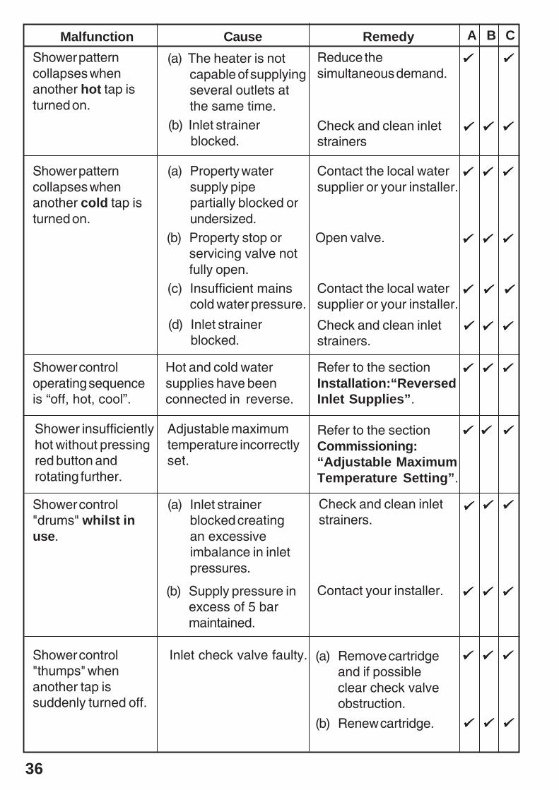
RemedyMalfunction CauseShower patterncollapses whenanother hot tap isturned on.
(a) Property watersupply pipepartially blocked orundersized.
Reduce thesimultaneous demand.
Shower patterncollapses whenanother cold tap isturned on.
Shower controloperating sequenceis “off, hot, cool”.
Shower insufficientlyhot without pressingred button androtating further.
Shower control"drums" whilst inuse.
Shower control"thumps" whenanother tap issuddenly turned off.
(a) The heater is notcapable of supplyingseveral outlets atthe same time.
(b) Property stop orservicing valve notfully open.
(c) Insufficient mainscold water pressure.
Hot and cold watersupplies have beenconnected in reverse.
Adjustable maximumtemperature incorrectlyset.
(a) Inlet strainerblocked creatingan excessiveimbalance in inletpressures.
Inlet check valve faulty.
Contact the local watersupplier or your installer.
Contact the local watersupplier or your installer.
Refer to the sectionInstallation:“ReversedInlet Supplies”.
Refer to the sectionCommissioning:“Adjustable MaximumTemperature Setting”.
Contact your installer.
(a) Remove cartridgeand if possibleclear check valveobstruction.
(b) Renew cartridge.
Open valve.
A B C
(d) Inlet strainerblocked.
Check and clean inletstrainers.
(b) Inlet strainerblocked.
Check and clean inletstrainers
Check and clean inletstrainers.
(b) Supply pressure inexcess of 5 barmaintained.
37
RemedyMalfunction Cause
(a) Heater appliancenot igniting due toinsufficient mainspressure.
Contact the local watersupplier or a CORGIregistered installer.
Open valve.
Wait until reheated.
Refer to “Widetemperaturefluctuations”.
Wait for hot water toreheat.
Renew cartridge. Referto the sectionMaintenance:“Cartridge Renewal”.
Renew ‘O’ seals withService Pack.
(c) Product hot or coldisolating valve notfully open.
(d) Hot water run out.
(a) Insufficient flowrate.
(b) Hot water supplytemperaturedropped.
(a) Pipework notflushed beforeconnecting showercontrol. (Internal ‘O’seals damaged).
(b) Cartridge or inletstrainer ‘O’ sealsdamaged.
No hot wateravailable
Shower starts warmand then runs cool.
Shower controlcannot be shut off.
No flow or low flowfrom shower head.
(a) Supply stop valveturned down or off.
(b) Inlet Strainersblocked.
(c) Hose or handsetblocked.
Open valve.
Clean or renew.
Clear blockage. Ifnecessary renew hoseor handset.
(d) Spray plateblocked.
Remove and clean.
A B C
Check and clean inletstrainers.
(e) Inlet strainerblocked.
Shower force toostrong.
Fit 9 l/m flow regulator.High pressure supplies.
(b) Heater appliancenot igniting due toappliance fault.
Contact a CORGIregistered installer.

38
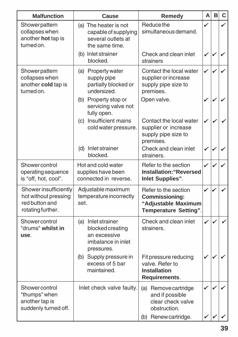
Installer Fault Diagnosis: refer to appliance diagram and customer faultdiagnosis
Read the section “Important Safety Information” first.
Providing the shower has been correctly installed and is operated in accordance withthe instructions contained in this guide, difficulties should not arise. If anymaintenance is required then it must be carried out by a competent tradesperson forwhom the fault diagnosis chart and maintenance instructions are provided. To work ongas heater appliances an installer MUST be CORGI registered. Before replacing anyparts ensure that the underlying cause of the malfunction has been resolved.
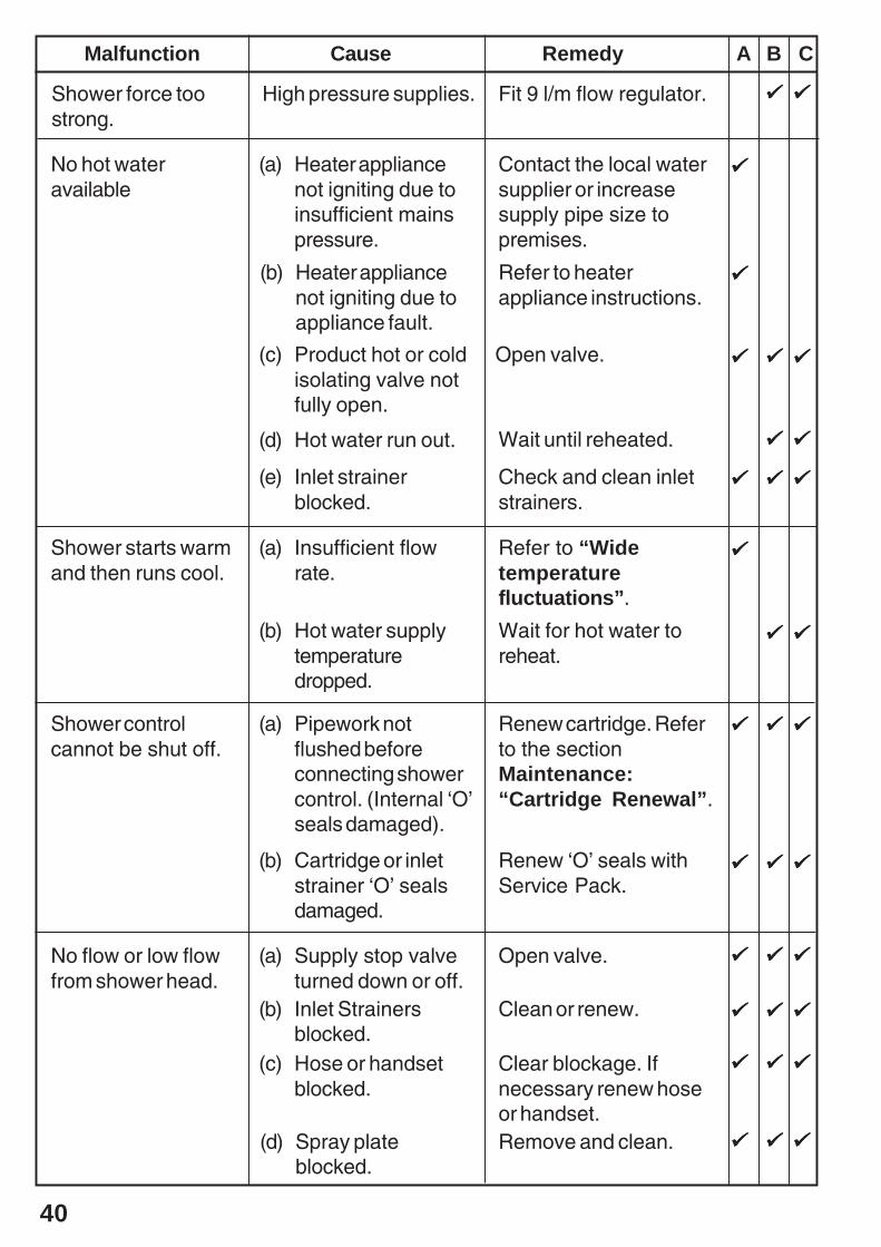
Key for applicability columnA - Instantaneous gas heated showers.B - Unvented mains pressure showers.C - Mains pressurised, instantaneous hot water, heated from thermal store showers.
Showerinsufficiently hot.
Wide temperaturefluctuations fromshower when noother draw-off isbeing made.
(a) Maximumtemperatureincorrectly set.
Reset adjustablemaximumtemperature.
(b) Heater not set onmaximum hot.
(c) Flow rate still toohigh.
Consult heaterinstructions for furtherinstructions.
Fit 9 l/min flow regulatorbetween shower controland hose.
Increase supply pipesize to premises.
(d) See also“Showerinsufficientlyhot”.
RemedyMalfunction Cause A B C
Check and clean inletstrainers.
(a) Insufficient flowrate causing theheater to cycle onand off.
(b) Insufficient waterpressure causingthe heater tocycle on and off.
(c) Heater not fullymodulating.
Refer to InstallationRequirements.
39
RemedyMalfunction CauseShower patterncollapses whenanother hot tap isturned on.
(a) Property watersupply pipepartially blocked orundersized.
Reduce thesimultaneous demand.
Shower patterncollapses whenanother cold tap isturned on.
Shower controloperating sequenceis “off, hot, cool”.
Shower insufficientlyhot without pressingred button androtating further.
Shower control"drums" whilst inuse.
Shower control"thumps" whenanother tap issuddenly turned off.
(a) The heater is notcapable of supplyingseveral outlets atthe same time.
(b) Property stop orservicing valve notfully open.
(c) Insufficient mainscold water pressure.
Hot and cold watersupplies have beenconnected in reverse.
Adjustable maximumtemperature incorrectlyset.
(a) Inlet strainerblocked creatingan excessiveimbalance in inletpressures.
Inlet check valve faulty.
Contact the local watersupplier or increasesupply pipe size topremises.
Contact the local watersupplier or increasesupply pipe size topremises.
Refer to the sectionInstallation:“ReversedInlet Supplies”.
Refer to the sectionCommissioning:“Adjustable MaximumTemperature Setting”.
Check and clean inletstrainers.
(a) Remove cartridgeand if possibleclear check valveobstruction.
(b) Renew cartridge.
Open valve.
A B C
(d) Inlet strainerblocked.
Check and clean inletstrainers.
(b) Inlet strainerblocked.
Check and clean inletstrainers
Fit pressure reducingvalve. Refer toInstallationRequirements.
(b) Supply pressure inexcess of 5 barmaintained.
40
RemedyMalfunction Cause
(a) Heater appliancenot igniting due toinsufficient mainspressure.
Contact the local watersupplier or increasesupply pipe size topremises.
Open valve.
Wait until reheated.
Refer to “Widetemperaturefluctuations”.
Wait for hot water toreheat.
Renew cartridge. Referto the sectionMaintenance:“Cartridge Renewal”.
Renew ‘O’ seals withService Pack.
(c) Product hot or coldisolating valve notfully open.
(d) Hot water run out.
(a) Insufficient flowrate.
(b) Hot water supplytemperaturedropped.
(a) Pipework notflushed beforeconnecting showercontrol. (Internal ‘O’seals damaged).
(b) Cartridge or inletstrainer ‘O’ sealsdamaged.
No hot wateravailable
Shower starts warmand then runs cool.
Shower controlcannot be shut off.
No flow or low flowfrom shower head.
(a) Supply stop valveturned down or off.
(b) Inlet Strainersblocked.
(c) Hose or handsetblocked.
Open valve.
Clean or renew.
Clear blockage. Ifnecessary renew hoseor handset.
(d) Spray plateblocked.
Remove and clean.
A B C
Check and clean inletstrainers.
(e) Inlet strainerblocked.
Shower force toostrong.
Fit 9 l/m flow regulator.High pressure supplies.
(b) Heater appliancenot igniting due toappliance fault.
Refer to heaterappliance instructions.
41
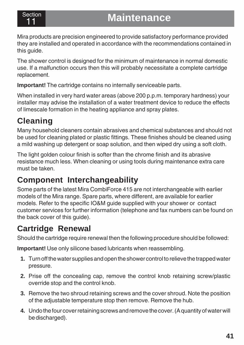
Mira products are precision engineered to provide satisfactory performance providedthey are installed and operated in accordance with the recommendations contained inthis guide.
The shower control is designed for the minimum of maintenance in normal domesticuse. If a malfunction occurs then this will probably necessitate a complete cartridgereplacement.
Important! The cartridge contains no internally serviceable parts.
When installed in very hard water areas (above 200 p.p.m. temporary hardness) yourinstaller may advise the installation of a water treatment device to reduce the effectsof limescale formation in the heating appliance and spray plates.
CleaningMany household cleaners contain abrasives and chemical substances and should notbe used for cleaning plated or plastic fittings. These finishes should be cleaned usinga mild washing up detergent or soap solution, and then wiped dry using a soft cloth.
The light golden colour finish is softer than the chrome finish and its abrasiveresistance much less. When cleaning or using tools during maintenance extra caremust be taken.
Component InterchangeabilitySome parts of the latest Mira CombiForce 415 are not interchangeable with earliermodels of the Mira range. Spare parts, where different, are available for earliermodels. Refer to the specific IO&M guide supplied with your shower or contactcustomer services for further information (telephone and fax numbers can be found onthe back cover of this guide).
Cartridge RenewalShould the cartridge require renewal then the following procedure should be followed:
Important! Use only silicone based lubricants when reassembling.
1. Turn off the water supplies and open the shower control to relieve the trapped waterpressure.
2. Prise off the concealing cap, remove the control knob retaining screw/plasticoverride stop and the control knob.
3. Remove the two shroud retaining screws and the cover shroud. Note the positionof the adjustable temperature stop then remove. Remove the hub.
4. Undo the four cover retaining screws and remove the cover. (A quantity of water willbe discharged).
11 MaintenanceSection
42
Cover Shroud
Cover ShroudRetaining Screws
Cartridge
Concealing Cap
Cover
Hub
Cover RetainingScrews
Control Knob
PlasticOverrideStop
Retaining Screw
AdjustableTemperatureStop
Plastic Pins
Cover 'O' Seal
Retaining Bush'O' Seal
'O' Seal
'O' Seal
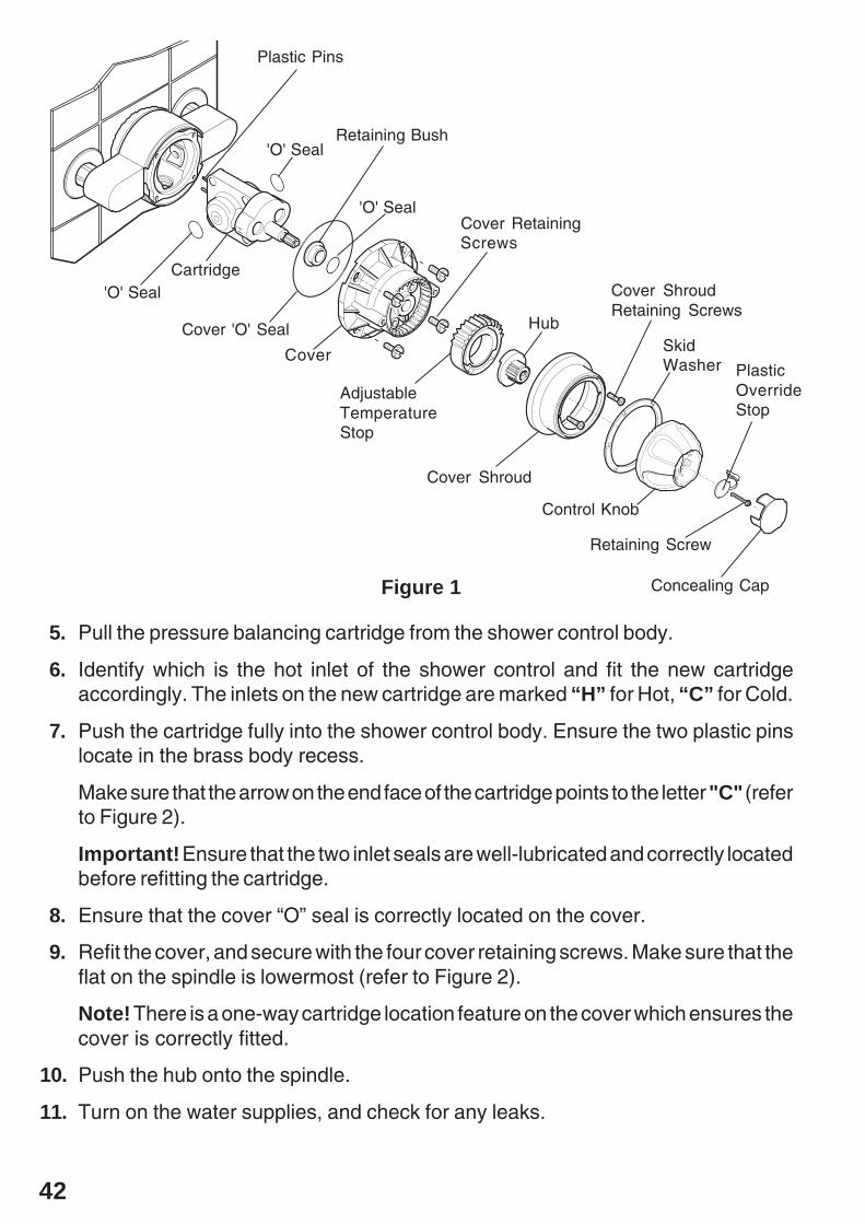
5. Pull the pressure balancing cartridge from the shower control body.
6. Identify which is the hot inlet of the shower control and fit the new cartridgeaccordingly. The inlets on the new cartridge are marked “H” for Hot, “C” for Cold.
7. Push the cartridge fully into the shower control body. Ensure the two plastic pinslocate in the brass body recess.
Make sure that the arrow on the end face of the cartridge points to the letter "C" (referto Figure 2).
Important! Ensure that the two inlet seals are well-lubricated and correctly locatedbefore refitting the cartridge.
8. Ensure that the cover “O” seal is correctly located on the cover.
9. Refit the cover, and secure with the four cover retaining screws. Make sure that theflat on the spindle is lowermost (refer to Figure 2).
Note! There is a one-way cartridge location feature on the cover which ensures thecover is correctly fitted.
10. Push the hub onto the spindle.
11. Turn on the water supplies, and check for any leaks.
Figure 1
SkidWasher

43
Arrow
End View Of Cartridge
Flat On Spindle
H C
12. Refit the adjustable temperature stop in its original position.
13. Temporarily fit the control knob (with the override button at the bottom). Rotate thecontrol knob anticlockwise until the desired temperature is achieved.Note the final position of the override button, e.g. 11 O’ clock. Rotate the controlknob to the “off” position.
14. The maximum temperature will now require resetting following the procedure“Adjustable Maximum Temperature Setting” in the section Commissioning.
Figure 2

44
Cartridge
Cover
Cover Retaining Screws
Plastic Pins
Cover 'O' Seal
Retaining Bush 'O' Seal
'O' Seal
'O' Seal
‘O’ Seal/Inlet Strainer RenewalShould the ‘O’ seals require renewing then follow the procedure below:
Important! Use only silicone based lubricants when reassembling.
1. Follow the procedure detailed in “Cartridge Renewal”: instructions 1. to 5. todismantle the shower control.
2. Check the ‘O’ seals on the cartridge hot and cold inlets for any signs of damage andrenew if necessary.
3. Remove the inlet strainers and check for damage, renew if necessary. Follow theprocedure detailed in “Inlet Strainer Cleaning”: instructions 2. to 4.
4. Push the cartridge fully into the shower control body. Ensure the two plastic pinslocate in the brass body recess.
Important! Ensure that the two inlet seals are well-lubricated and correctly locatedbefore refitting the cartridge.
5. Check the cartridge spindle ‘O’ seal (fitted in the cover) for signs of damage andrenew if necessary. Fit the spindle ‘O’ seal and retaining bush into the cover.
6. Check the cover ‘O’ seal for signs of damage and renew if necessary.
7. Follow the procedure detailed in “Cartridge Renewal”: instructions 8. to 14. toreassemble the shower control.
Figure 3
Inlet Strainer Unit

45
Inlet Strainer CleaningShould the inlet strainer units require cleaning or renewal then follow the procedurebelow:
Important! Use only silicone based lubricants when reassembling.
1. Follow the procedure detailed in “Cartridge Renewal”: instructions 1. to 5. todismantle the shower control.
2. Pull the inlet strainer units from the valve body.
3. Clean the complete strainer unit under running water. Check for damage and renewthe whole unit if necessary.
4. Refit the strainer units. The strainer units can only be fitted one way (refer toFigure 4).
Important! Ensure the 'O' seals on the inlet strainers are well-lubricated beforerefitting.
5. Follow the procedure detailed in “Cartridge Renewal”: instructions 7. to 14. toreassemble the shower control.
Cover
Cover RetainingScrews
Plastic Pins
Cover 'O' Seal
'O' Seal
Figure 4
Cartridge
Inlet Strainer Unit
46
Spare PartsSection12
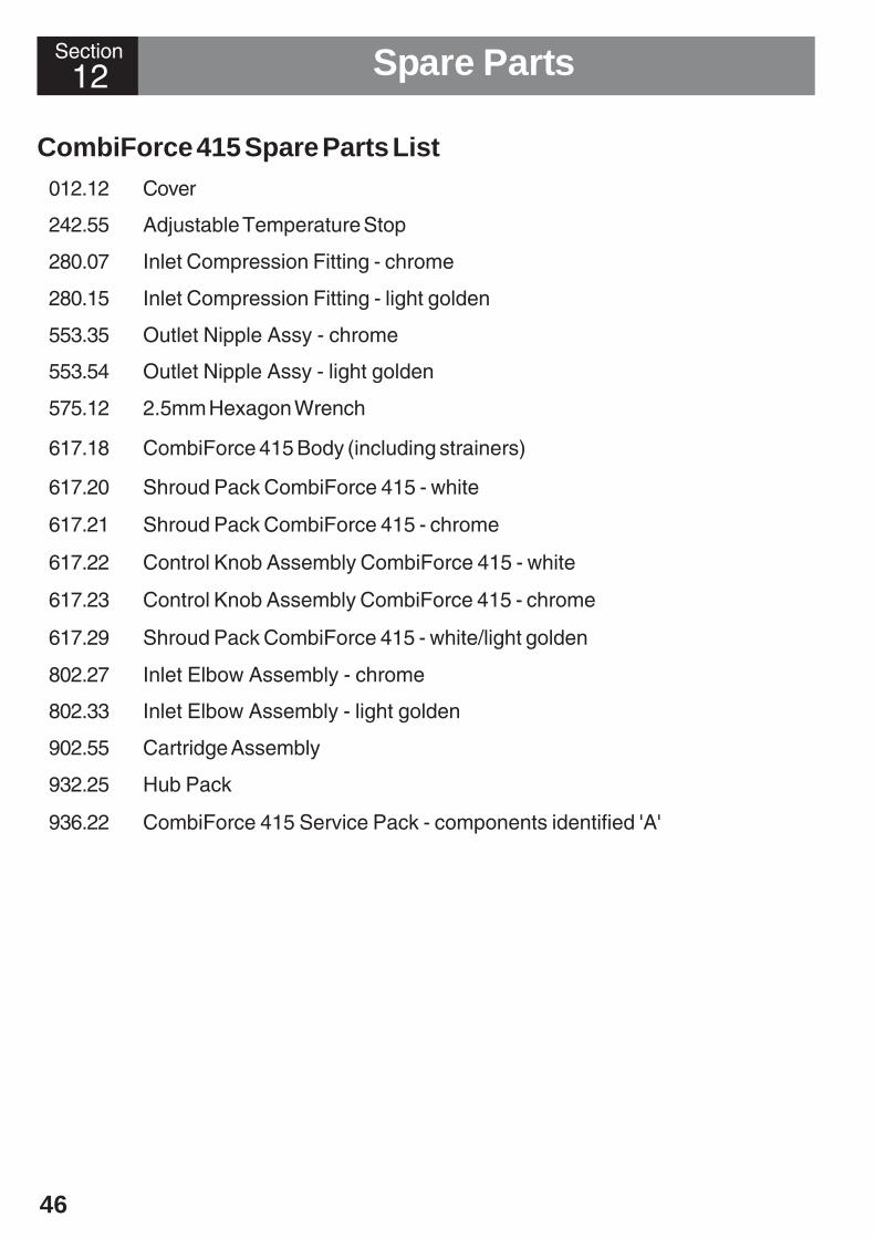
CombiForce 415 Spare Parts List012.12 Cover
242.55 Adjustable Temperature Stop
280.07 Inlet Compression Fitting - chrome
280.15 Inlet Compression Fitting - light golden
553.35 Outlet Nipple Assy - chrome
553.54 Outlet Nipple Assy - light golden
575.12 2.5mm Hexagon Wrench
617.18 CombiForce 415 Body (including strainers)
617.20 Shroud Pack CombiForce 415 - white
617.21 Shroud Pack CombiForce 415 - chrome
617.22 Control Knob Assembly CombiForce 415 - white
617.23 Control Knob Assembly CombiForce 415 - chrome
617.29 Shroud Pack CombiForce 415 - white/light golden
802.27 Inlet Elbow Assembly - chrome
802.33 Inlet Elbow Assembly - light golden
902.55 Cartridge Assembly
932.25 Hub Pack
936.22 CombiForce 415 Service Pack - components identified 'A'

47
575.12
617.20617.21617.29
280.07280.15
553.35553.54
802.33
902.55
012.12
802.27
617.22617.23
617.18
A
A
932.25
A
A
A
A
A
A
CombiForce 415 Spare Parts Diagram
A
A
617.20617.21617.29
242.55
48
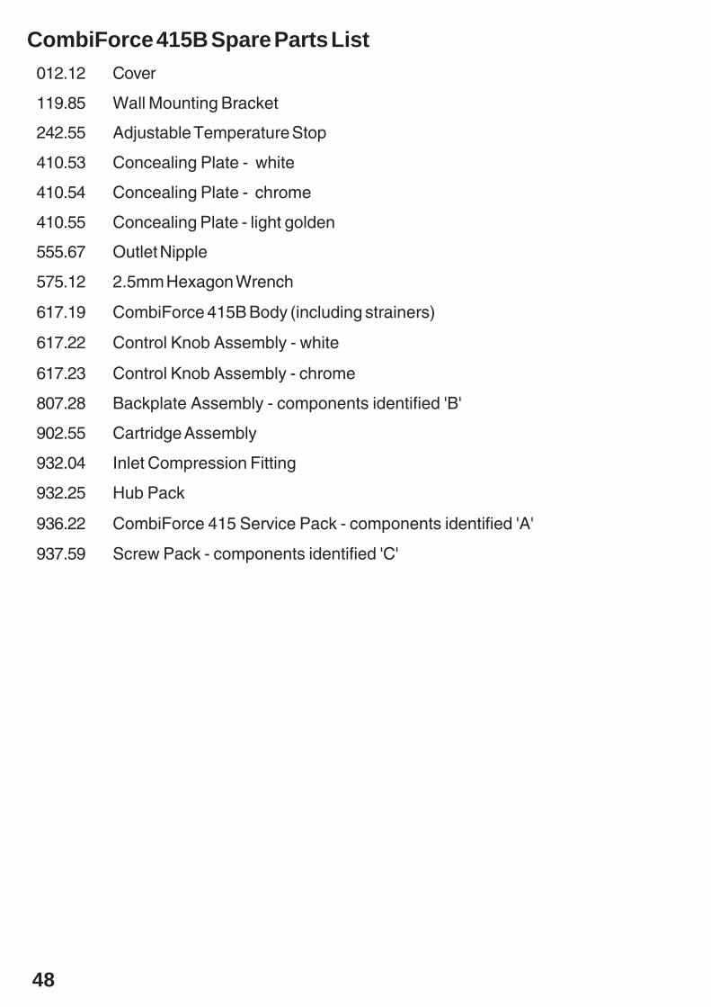
CombiForce 415B Spare Parts List012.12 Cover
119.85 Wall Mounting Bracket
242.55 Adjustable Temperature Stop
410.53 Concealing Plate - white
410.54 Concealing Plate - chrome
410.55 Concealing Plate - light golden
555.67 Outlet Nipple
575.12 2.5mm Hexagon Wrench
617.19 CombiForce 415B Body (including strainers)
617.22 Control Knob Assembly - white
617.23 Control Knob Assembly - chrome
807.28 Backplate Assembly - components identified 'B'
902.55 Cartridge Assembly
932.04 Inlet Compression Fitting
932.25 Hub Pack
936.22 CombiForce 415 Service Pack - components identified 'A'
937.59 Screw Pack - components identified 'C'
49
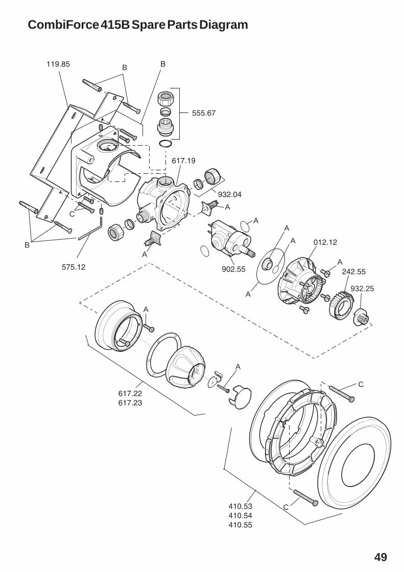
CombiForce 415B Spare Parts Diagram
617.22617.23
119.85 B
555.67
932.04
617.19
012.12
902.55
410.53410.54410.55
A
A
A
932.25A
AA
A
C
C
B
C
B
AA
242.55575.12

50
AccessoriesDCV-H: An outlet double check valve, requiring a minimum inlet supply pressure of0.5 bar, which has been designed to prevent the backflow or backsiphonage ofpotentially contaminated water, through shower controls which are fitted with a flexiblehose as part of the outlet shower fitting. Available as an optional accessory from yourMira stockist.
DCV-H Outlet double check valve
9 litre/min Outlet Flow Regulator (Part No. 146.84 ): Designed to limit the flowrate in high pressure installations. If the maximum obtainable water temperature at theshower outlet is not sufficiently hot, fitting a flow regulator may increase the outletwater temperature and may also reduce the shower force at the outlet (seeCommissioning). Available from Mira customer services.
9 litre/minute Flow Regulator
Section13

51
Appendix Notes
P3740/3 © Kohler Mira Limited, August 2003
Section Customer ServiceGuarantee of Quality After Sales Service
Mira ShowersKohler Mira LtdCromwell Road,Cheltenham GL52 5EP.
Mira is a registered trade mark.The company reserves the right to alter productspecifications without notice.
www.mirashowers.com
Within the guarantee period we will resolve defects, free ofcharge, by repairing or replacing parts or modules as we maychoose.
Not covered by this guarantee:Damage or defects arising from incorrect installation, improperuse or lack of maintenance, including build-up of limescale.
Mira Showers guarantee products against any defect ofmaterials or workmanship for one year from the date ofpurchase (2 years for Mira Select and 3 years for Mira Excelranges).
What to do if something goes wrong
Should this not resolve the difficulty, simply contact ourCustomer Services who will give every assistance, and ifnecessary arrange for our service engineer to visit.
If later the performance of your shower declines, consult thismanual to see whether simple home maintenance is required.Please call our Customer Services to talk the difficultythrough, request service under guarantee if applicable, ortake advantage of our comprehensive After-Sales service.
Payment should be made directly to the Service Engineer/Agent, using Visa, Access or a cheque supported by abanker’s card.
England, Scotland & Wales
Mira Showers Customer ServicesTelephone: 01242 2628888.30am to 5pm Working days (4.30pm Fri)8.30 am to 12.30pm SaturdayE-mail: [email protected]: 01242 282595By Post: Cromwell Road
CheltenhamGloucester GL52 5EP
As part of our quality and training programme callsmay be recorded or monitored
For Customers in Northern IrelandWm H Leech & Son LtdTelephone: 028 9044 9257 – Mon to Fri 9 am-5pmFax: 028 9044 9234 – 24 hoursPost: Maryland Industrial Estate
Ballygowan RoadMoneyreagh, Co DownBT23 6BL
For Customers in Republic of IrelandModern Plant LtdTelephone: Dublin 01 4591344 - Mon to Fri 9am to 5pmFax: Dublin 01 4592329 – 24 hoursPost: Otter House
Naas RoadClondalkinDublin 22
To validate the guarantee, please return your completedregistration card.
To be free of charge, service work must only be undertakenby Mira Showers or our approved agents in Northern Irelandand Republic of Ireland.Service under this guarantee does not affect the expirydate. The guarantee on any exchanged parts or productends when the normal product guarantee period expires.
Damage or defects if the product is taken apart, repaired ormodified by any person not authorised by Mira Showers or ourapproved agents.
This guarantee is in addition to your statutory and otherlegal rights.
Before using your showerPlease take the time to read and understand the operatingand safety instructions detailed in this manual.
If when you first use your shower it doesn’t function correctly,first contact your installer to check that installation andcommissioning are satisfactory and in accordance with theinstructions in this manual. We are on-hand to offer you or yourinstaller any advice you may need.
Spare Parts
Our Customer Services Team is comprehensively trainedto provide every assistance you may need: help andadvice, spare parts or a service visit.
We maintain an extensive stock of spares, and aim to havefunctional parts available for ten years from the date offinal manufacture of the product.
Spares can be purchased from approved stockists ormerchants (locations on request) or direct from CustomerServices.
Note! In the interests of safety, spares requiring exposureto mains voltages can only be sent to competent persons.
Spares direct will normally be despatched within twoworking days. Payment can be made by Visa or Accessat the time of ordering. Should payment by cheque bepreferred a pro-forma invoice will be sent.
Our Service Force is available to provide a quality service ata reasonable cost. You will have the assurance of a Miratrained engineer/agent, genuine Mira spares – and a 12 monthguarantee on the repair.
Service
To contact us: