pressure fluctuation in a vaned diffuser downstream from...
TRANSCRIPT
International Journal of Rotating Machinery, 9: 285–292, 2003Copyright c© Taylor & Francis Inc.ISSN: 1023-621XDOI: 10.1080/10236210390147489
Pressure Fluctuation in a Vaned DiffuserDownstream from a Centrifugal Pump Impeller
Akinori Furukawa and Hisasada TakaharaFaculty of Engineering, Kyushu University, Fukuoka, Japan
Takahiro Nakagawa and Yusuke OnoGraduate School of Engineering, Kyushu University, Fukuoka, Japan
Periodic flows downstream from a centrifugal pump im-peller in vaneless and vaned diffusers were measured byusing a single hole yawmeter and a phase-locked samplingmethod. The flows were also calculated by an inviscid flowanalysis using the blade-surface singularity method. The pe-riodic variations in calculated static pressure with the im-peller rotating quantitatively agree well with the measuredones. The flow behaviors in the vaned diffuser are discussed,citing measured and calculated results. The potential inter-action between the impeller and the diffuser blades appearsmore strongly than the impeller-wake interaction. The ap-pearance of static pressure fluctuations due to the impeller’srotating in the fully vaned zone is different from that in thesemivaned zone of the diffuser. The existence of the periph-eral blade surface of the impeller outlet with an outlet edgeof the pressure surface causes violent pressure fluctuationsin the vaned diffuser.
Keywords Blade rows interaction, Centrifugal pump impeller, Dif-fuser, Flow measurement, Inviscid flow analysis, Pressurefluctuation
Diffuser pumps with high head have recently been used in var-ious kinds of large-scale industrial plants, whereas small pumpswith higher speeds are demanded by limitations on manufactur-ing cost and installation space. The performance of a diffuserpump with high head would be improved by the reduction offlow losses in the diffuser, yielding high pressure recovery, andin the impeller. Additionally, in a diffuser with a combined im-peller and vane, the interaction of the impeller and diffuser blades
Received 25 June 2002; accepted 1 July 2002.Address correspondence to Akinori Furukawa, Department of Engi-
neering, Kyushu University 36, 6-10-1 Hakozaki, Higashi-ku, Fukuoka,812-8581, Japan. E-mail: [email protected]
might cause a severe vibration problem. Regarding the flow in adiffuser downstream from the impeller: although there are manyexperimental and theoretical reports (Arndt et al., 1990; Qin andTsukamoto, 1997; Shi and Tsukamoto, 1999; Sinha and Katz,1999; Zhu and Kamemoto, 1999), at the present stage, it is notsufficient to understand flow mechanism in the diffuser and theinteraction of the impeller and diffuser blades.
In our previous report (Furukawa et al., 2000), it was shownthat even the solution of an inviscid flow analysis by simple cal-culations was able to simulate the real flow in a vaneless diffuserdownstream of a centrifugal impeller. In this article, the methodis extended to a flow in an impeller-and-vaned-diffuser combi-nation, and calculated and measured results are compared. Thevelocity and pressure fluctuations caused in the vaned diffuserby the interaction of the blades is clarified, and the effects ofimpeller and diffuser blade positions on the pressure fluctuationare discussed.
EXPERIMENTAL APPARATUSFigure 1 shows a sectional view of the pump equipment with
a vertical rotating shaft. Flowing into the impeller, 1, througha Venturi flowmeter and boost pump from an open tank, wateris discharged to a parallel-walled diffuser, 2, with a height ofb= 30 mm, which is the same as the impeller blade height; thewater overflows after forming a free surface in channel, 3, whichis equipped to produce an axisymmetrically periodic flow; andit then returns to the open tank. In this experiment, an oil sealwas attached to the pump’s suction cover-ring to suppress arecirculating flow from the outlet to the inlet through a spacebetween the impeller shroud and the casing.
Figure 2 shows the shapes of the test impeller and diffuser.The impeller has six two-dimensional blades (Zi = 6) with theinlet and outlet diameters of 200 and 400 mm. The suction andpressure surface-blade outlet angles areβb2s=βb2p= 18.1 de-grees, and the peripheral blade thickness istθ2= 35.0 mm at theoutlet. Eleven two-dimensional blades (Zd= 11) with the inlet
285

286 A. FURUKAWA ET AL.
FIGURE 1Sectional view of pump equipment.
angleαb3c= 22.8 degrees on a blade center line and the inlet andoutlet diameters of 420 and 600 mm (corresponding to the ra-dius ratio of the impeller outletR= r/r2= 1.05 and 1.50) wereinstalled in the diffuser. The diffuser blade was cut by a circulararc of the radius of 3 and 110 mm on the inlet suction (con-vex) and pressure (concave) surfaces, respectively. In the caseof Zi = 6 andZd= 11, the dominant frequency of the pressurefluctuation in the diffuser due to the impeller blades’ rotatingtakes 2Zi N, whereN is a rotational speed of the impeller.
The flow-measuring probes were placed at six radial sectionsof the ratio R= 1.03, 1.06, 1.10, 1.15, 1.28, and 1.50 on thediffuser wall of the impeller shroud side. The opposite wall ofthe disk side is movable so flow can be measured at five cir-cumferential positions, line 1 through line 5, on the diffuser’sblade-to-blade passage (see Fig. 2). The periodic flow with thestatic pressurep and the absolute velocityV , the radial andcircumferential components of which denoteVr and Vθ , re-spectively, downstream of the impeller was measured at sevenpositions— 0,± 6,± 12, and± 13.5 mm from the center of thediffuser’s height. A rotating total-pressure probe with a singlehole (Takahara et al., 1989) was used with the sampling methodof the phase-locked to the impeller’s rotation. The pressure at theprobe head was transferred to the sensor through the connectingpipe, which is filled with a silicone oil. The response frequencyof the pressure measuring system was about 1 kHz.
FIGURE 2Test impellers and a vaned diffuser.
The pump impeller speed was always kept atN= 200 rpm.The flow measurement was executed at a flow coefficient ofφ= 0.146, where the waving motion of the free surface in chan-nel, 3, was not observed. Here the flow coefficientφ was denotedas the ratio of the averaged radial velocity componentVr 2 to theimpeller’s rotating velocityU2 at the impeller outlet, and thepressure coefficientψs was denoted as the ratio of the staticpressure rise, based on the pump’s inlet total pressure ofρU2
2/2,whereρ is the water density.
DESCRIPTION OF INVISCID FLOW CALCULATIONFigure 3 shows the calculated and measured results in the case
of the combination of an impeller and a vaneless diffuser. In thiscalculation, taking into account the three-dimensional boundarylayer model (Furukawa et al., 1987, 1990), discrete vortexes aredistributed on the impeller blade surfaces, including the inletand outlet peripheral surfaces, in order to reproduce the bladeshape precisely. This method is called the blade-surface singu-larity method. The strength of the vortex at the outlet edge of thesuction surface is assumed to take zero as the Kutta condition,and other discrete vortex are solved from the tangential condi-tions of the relative flow along the blade surface. The horizontalaxisθ in Figure 3 is denoted as the circumferential position rel-ative to the impeller, rotating where the positions of the outletedge of the impeller’s pressure surface correspond toθ = 0 de-grees and−60 degrees. As can be seen in Figure 3, both resultsgive the same variations in velocity and pressure with the im-peller rotating, such as a low-pressure and velocity region nearthe sameθ position that corresponds to the outlet edge of theblade’s pressure surface. The behavior of wake, which flowsalong the relative streamline, cannot be simulated because ofinviscid flow calculation.
The good agreement between calculated and measured re-sults in Figure 3 encourages the extending of this method tocalculations involving a combined impeller and vaned diffuser.In the extended calculation, discrete vortexes are also distributedon the impeller and diffuser blade surfaces; their strength is ob-tained from the tangential condition of the flow on blade surfaceswith the Kutta condition, under the condition of instantaneouslyfixed blade positions of the impeller and diffuser. The calcula-tion of the velocity field is continued at various blade positions,neglecting the vortexes shed from blades for the sake of sim-plicity at the present stage, though each blade circulation of theimpeller and diffuser,0i and0d, respectively, is changed, withthe impeller rotating as shown in Figure 4. Here the horizontalaxist∗ of Figure 4 is denoted as the dimensionless time based onthe rotating time of the impeller 2π /(Zi N), meaning thatt∗ = 0when the center of the peripheral outlet surface of the impellerblade is located at the same circumferential position as the lead-ing edge of the diffuser blade, as shown in Figure 5. In velocitycalculation, a shape modified by the displacement thickness ofthe boundary layers, obtained in vaneless diffuser calculation,was used for the impeller blade but not used for the diffuserblade.

PRESSURE FLUCTUATION IN A DIFFUSER 287
FIGURE 3Circumferential distributions of static pressure and velocity in
a vaneless diffuser. (A) Static pressure. (B) Velocity.
Static pressure can be obtained from an unsteady Bernoulli’sequation for an inviscid flow analysis. The upstream conditionis not prescribed for the absolute streamline through the vaneddiffuser because fluid with different total pressures periodicallyflows out from the impeller. It is found from Figure 4 that thesum of all impeller blade circulations is almost independent oft∗and takes constant. This fact suggests that any streamline has thesame total pressure at the infinite section ofr =∞ independentlyof t∗, as Equation (1) shows:
ρVuU |r=∞ =zi∑
n=1
0nN. [1]
FIGURE 4Time variation of blade circulation with impeller rotating.
FIGURE 5Definition of t∗ = 0 and fully and semivaned zones.

288 A. FURUKAWA ET AL.
Therefore, the local static pressurep is related to Equation (2):
p∞ + ρ V2∞2= ρVuU |r=∞ = p+ ρ V2
2+ ρ ∂ϕ
∂t. [2]
Here,ϕ(t) means an instantaneous velocity potential, which isobtained from the calculated discrete vortexes as follows:
ϕ(t) = q
2πlogr +
Zi∑n=1
Ki∑ki=1
µnki(t)
2π12nki(t)1snki
+Zd∑
m=1
Kd∑kd=1
µnkd(t)
2π12nkd(t)1snkd [3]
and
12lk∗ = tan−1 r sinθ − rlk∗ sinθlk∗
r cosθ − rlk∗ cosθlk∗[4]
FIGURE 6Comparison of measured and calculated results of flow fluctuations in a vaned diffuser. (A) Static pressure. (B) Velocity.
in which q is the specified flow rate,1s the length of bladesurface line element,µ the vortex strength, (r , θ ) and (rlk , θlk)the positions of calculating and vortex points. The subscriptsof l in Equation (4) meansn or m in Equation (3) and also∗ inEquation (4) meansi ord in Equation (3). After calculatingϕ(t)at various blade positions, the time derivative∂ϕ/∂t is evaluatedas the finite difference equation at a calculating point.
RESULTS AND DISCUSSIONFigure 6 shows the time variations of the pressure coefficient
ψs and the dimensionless velocityV/U2 at measuring points atthe middle height of passagez/b= 0.5 on lines 1 (pressure side),3 (center), and 5 (suction side) in Figure 2. Measured results areexpressed as solid lines and calculated results as dotted lines inFigure 6. In comparison with the results in the vaneless diffuserin Figure 3, those in the vaned diffuser become wavier. The wake
PRESSURE FLUCTUATION IN A DIFFUSER 289
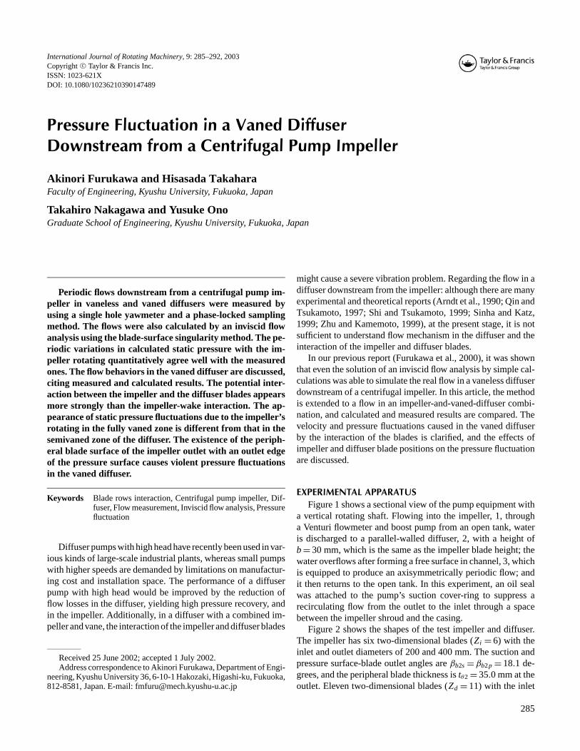
FIGURE 7Position of impeller and diffuser blades.
region of real fluid flow, presumed on higher absolute velocity, aswell as flow in the vaneless diffuser in Figure 3, is also depictedin Figure 6B.
The next three distinct points are found from Figure 6. Thepassing time at the outlet edge of the pressure surface of theimpeller blade through the same circumferential position (θ = 0degrees and−60 degrees) is expressed as a dot-and-dash line foreach measuring point in Figure 6; the passing time at the outletedge through the zone parting line between semivaned and fullyvaned zones shown in Figure 5 is also expressed as a brokenline of A in Figure 6A. At the time line of A, the impeller anddiffuser blades are located as shown in Figure 7. Then at the firstpoint, the lowest values of pressure and velocity occur almost ondot-and-dash lines for measuring points less than R< 1.15 in thesemivaned zone of SV. These variations have a phase similar tothose in the vaneless diffuser in Figure 3. For measuring points inthe fully vaned zone of FV, however, the lowest value of pressureappears on time line A. As the second point, pressure is rapidlydecreased from time line B to C for all measuring points, whilethe velocity is not increased. At time B, the outlet peripheralsurface of the impeller blade and the leading edge of diffuserblade are radially overlapped as shown in Figure 7. Therefore,the outlet flow from the impeller smoothly enters the diffuserpassage. On the other hand, at time C, the outlet surface of theimpeller blade makes the passage inlet area narrower on thepressure side of the diffuser, and the smooth entry of the outletflow is disturbed. At the third point, the measured pressure in thesemivaned zone is slightly decreased at timet∗, which equalsabout 0.6 (0.7 for the calculated pressure).
The time variation of the measured pressure in the vaneddiffuser is more wavy than that of the velocity, as shown inFigure 6, and the variation of velocity is not so different fromthat in the vaneless diffuser in Figure 3B. In addition to these,the calculated results agree well with the measured results, inspite of neglecting in the calculation the vortexes shed from theimpeller blade. This result implies that the potential interactionbetween the impeller and the diffuser blades is more dominantthan the wake interaction in the case of the combination of acentrifugal impeller and a vaned diffuser. It indicates, therefore,that the present calculation is usable to discuss the effects ofrelative positions and shapes of the impeller and diffuser bladeson pressure fluctuations in a vaned diffuser.
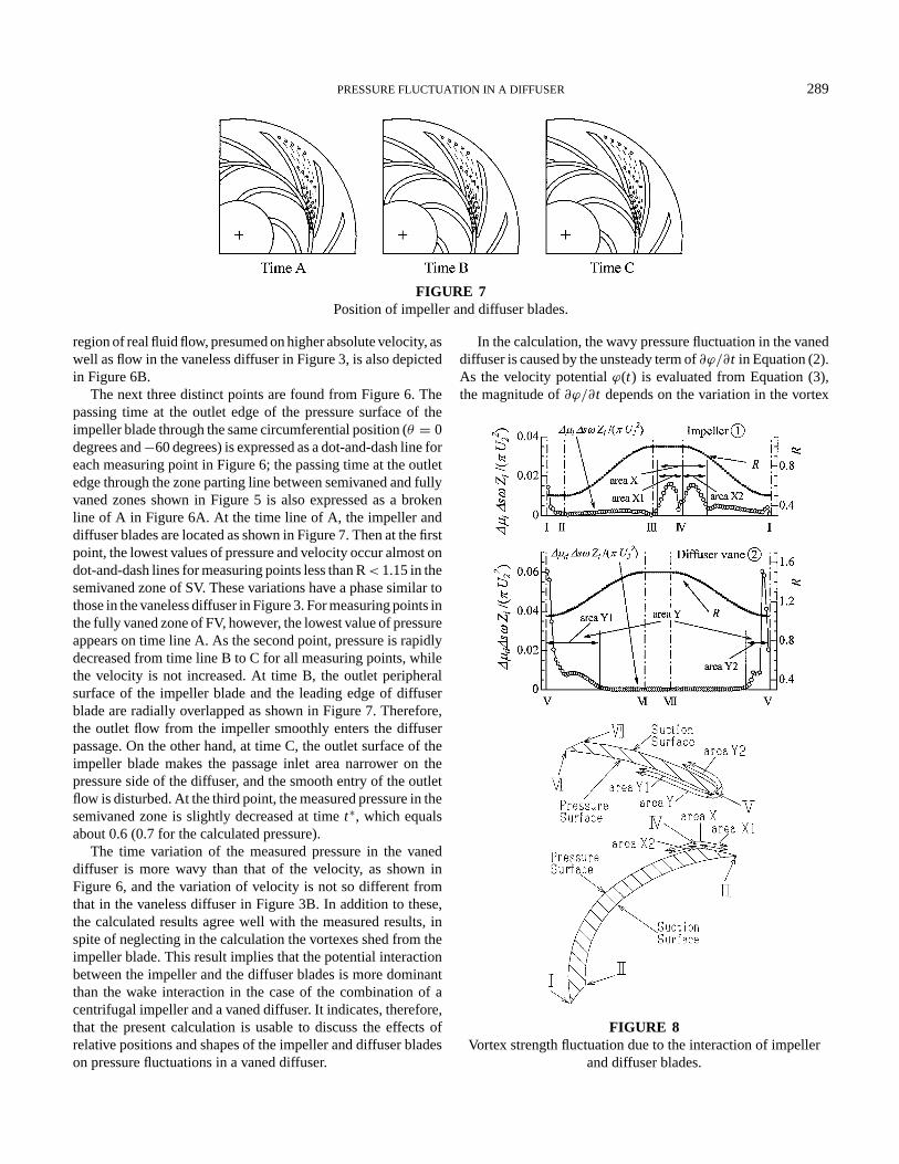
In the calculation, the wavy pressure fluctuation in the vaneddiffuser is caused by the unsteady term of∂ϕ/∂t in Equation (2).As the velocity potentialϕ(t) is evaluated from Equation (3),the magnitude of∂ϕ/∂t depends on the variation in the vortex
FIGURE 8Vortex strength fluctuation due to the interaction of impeller
and diffuser blades.

290 A. FURUKAWA ET AL.
FIGURE 9Pressure fluctuations due to the change of vortex strengths in areas of X and Y on the blades.
strength distributed on the impeller and diffuser blade surfaces.Figure 8 shows the amplitude of the vortex strength’s fluctuation1µ on the blade surfaces, in which positions of I to VII on thehorizontal axis on the left of the figure are representative of thepositions on the blade surfaces in the figure on the right. It isfound from Figure 8 that the large amplitude of1µ appears in
FIGURE 10Contours of measured static pressure fluctuations in blade-to-blade passages in a vaned diffuser.
the area of X near the outlet edge of the impeller-blade pressuresurface and in the area of Y near the leading edge of the diffusersurface. Thus, by using only vortexes in the areas of X of a im-peller blade, of Y1 on the pressure surface of a diffuser blade,and of Y2 on the suction surface of the adjacent diffuser bladefacing a passage, the time variation of∂ϕ/∂t was evaluated at

PRESSURE FLUCTUATION IN A DIFFUSER 291
the measuring points. Figure 9 shows the calculated results. It isfound from the solid line in Figure 9 that the pressure fluctuationis almost attributable to the vortex strength fluctuation in areaX of the impeller blade. It is mentioned on the three distinctpoints demonstrated in Figure 6A as follows. The appearance ofthe minimum pressure in the fully vaned zone cannot be repro-duced on time line A in Figure 9 because of taking account of thevortexes only in the areas of X and Y in this evaluation. It is rec-ognized, however, that the abrupt decrease in pressure from timeline B to C and the slight decrease in pressure in the semivanedzone at timet∗ is about 0.7 and can be found in Figure 9. There-fore, it is known from this result that the severe pressure fluctua-tion in the vaned diffuser is caused by the outlet edge of the pres-sure surface of an impeller blade with a thick peripheral surface.
Flow measurement was performed at seven positions on thediffuser height on lines 1 through line 5 in five radial sections.After calculating the peak-to-peak difference of pressure fluctu-ation1ψs = ψsmax.− ψsmin., the contour map1ψs is obtainedas shown in Figure 10. It is found that the behavior of pressurefluctuation is almost two-dimensional independent of diffuserheight direction. Figure 11 illustrates the blade-to-blade distri-butions of measured1ψs in the middle-height of the diffuser, incomparison with the calculated distributions from the inviscidflow analysis. The distribution of calculated1ψs gives a ten-dency similar to that of the measured tendency. Figure 12 showsthe contour of predicted1ψs in the diffuser passage. It is found
FIGURE 11Comparison between the measured and calculated results of
static pressure fluctuations.
FIGURE 12Contours of the calculated static pressure fluctuation in a vaned
diffuser.
from these figures that the region of the large pressure fluctua-tion appears in the pressure and suction sides just downstreamfrom the leading edge, and that pressure in the pressure side fluc-tuates in a relatively large amplitude. The pressure fluctuation,however, becomes weakened when it with approaches the outletsection of the diffuser.
CONCLUSIONSThe downstream flow of a centrifugal impeller in a vaned
diffuser with parallel walls was measured and compared with theresults calculated by an inviscid flow analysis using the blade-surface singularity method. The interaction between the impellerand the diffuser blades is discussed in this article. The resultsare summarized as follows.
1. The potential interaction, causing pressure fluctuation, ap-pears to dominate in comparison with the wake interaction.
2. The flow analysis using the blade-surface singularity method,neglecting shed vortexes from the impeller blades for sim-plicity, enables the reproduction of measured pressure fluctu-ations due to impeller and diffuser blade interaction satisfac-torily and is usable to discuss the effects of the blades shapesof the impeller and diffuser on the pressure fluctuation.
It should be mentioned here that the calculated resultswould give greater quantitative agreement with the measuredones if the effects of shed vortexes are taken into account.
3. The existence of the outlet edge of the pressure surface andthe thick peripheral outlet surface of an impeller blade cause

292 A. FURUKAWA ET AL.
quite a large fluctuation of pressure during the passage of thevaned diffuser. Therefore, the outlet shape of the impellerblade should be considered in studying the problem of theinteraction between the impeller and diffuser blades.
REFERENCESArndt, N., Acosta, A. J., Brennen, C. E., and Caughey, T. K. 1990.
Experimental investigation of rotor/stator interaction in a centrifugalpump with several vaned diffusers.ASME Journal of Turbomachin-ery111:213–221.
Furukawa, A., Cheng, C., and Takamatsu, Y. 1990. Studies on estimat-ing the performances of impellers with cut-down of the blade edgeof the centrifugal pumps by the surface singularity method,JSMEInternational Journal II33-3:525–530.
Furukawa, A., Cheng, C., Sekiya, T., and Takamatsu, Y., 1987. Flowanalysis in two-dimensional impeller of centrifugal pump by sur-face singularity method combined with a flow-model of three-dimensional boundary layer.Proceedings of the 2nd China-JapanJoint Conference on Fluid Machinery, Xi’an, 1–8.
Furukawa, A., Nakagawa, T., and Takahara, H. 2000. Downstream flowof centrifugal pump impeller in vaneless diffuser.Mem. Fac. Eng.,Kyushu University60-2:21–33.
Nakagawa, T., Furukawa, A., and Takahara, H. 2001. Flow behaviordownstream of diffuser pump impeller.Turbomachinery29-2:110–118. [In Japanese.]
Qin, W., and Tsukamoto, H. 1997. Theoretical study of pressure fluc-tuations downstream of a diffuser pump impeller. 2: Effects of vo-lute, flow rate and radial Gap.ASME Journal of Fluid Engineering119:653–658.
Shi, F., and Tsukamoto, H. 1999. Numerical studies of effects of flowrate and radial gap on pressure fluctuations downstream of a diffuserpump impeller.Paper FEDSM99-7314, The 3rd ASME/JSME JointFluid Engineering Conference, 1–7.
Sinha, M., and Katz, J. 1999. The onset and development of rotating stallwithin a centrifugal pump with a vaned diffuser,Paper FEDSM99-7198, The 3rd ASME/JSME Joint Fluid Engineering Conference,1–7.
Takahara, H., Takamatsu, Y., Kouno, I., and Kurahara, T. 1989. A studyon flow measurement scheme by stepwise rotation of total-pressuretube in flow with steep velocity and pressure gradients.Transactionsof the JSME55-510B:413–418.
Zhu, B., and Kamemoto, K. 1999. Simulation of the unsteady interac-tion of a centrifugal impeller with its diffuser by an advanced vortexmethod.Paper FEDSM99-6821, The 3rd ASME/JSME Joint FluidEngineering Conference, 1–9.

International Journal of
AerospaceEngineeringHindawi Publishing Corporationhttp://www.hindawi.com Volume 2010
RoboticsJournal of
Hindawi Publishing Corporationhttp://www.hindawi.com Volume 2014
Hindawi Publishing Corporationhttp://www.hindawi.com Volume 2014
Active and Passive Electronic Components
Control Scienceand Engineering
Journal of
Hindawi Publishing Corporationhttp://www.hindawi.com Volume 2014
International Journal of
RotatingMachinery
Hindawi Publishing Corporationhttp://www.hindawi.com Volume 2014
Hindawi Publishing Corporation http://www.hindawi.com
Journal ofEngineeringVolume 2014
Submit your manuscripts athttp://www.hindawi.com
VLSI Design
Hindawi Publishing Corporationhttp://www.hindawi.com Volume 2014
Hindawi Publishing Corporationhttp://www.hindawi.com Volume 2014
Shock and Vibration
Hindawi Publishing Corporationhttp://www.hindawi.com Volume 2014
Civil EngineeringAdvances in
Acoustics and VibrationAdvances in
Hindawi Publishing Corporationhttp://www.hindawi.com Volume 2014
Hindawi Publishing Corporationhttp://www.hindawi.com Volume 2014
Electrical and Computer Engineering
Journal of
Advances inOptoElectronics
Hindawi Publishing Corporation http://www.hindawi.com
Volume 2014
The Scientific World JournalHindawi Publishing Corporation http://www.hindawi.com Volume 2014
SensorsJournal of
Hindawi Publishing Corporationhttp://www.hindawi.com Volume 2014
Modelling & Simulation in EngineeringHindawi Publishing Corporation http://www.hindawi.com Volume 2014
Hindawi Publishing Corporationhttp://www.hindawi.com Volume 2014
Chemical EngineeringInternational Journal of Antennas and
Propagation
International Journal of
Hindawi Publishing Corporationhttp://www.hindawi.com Volume 2014
Hindawi Publishing Corporationhttp://www.hindawi.com Volume 2014
Navigation and Observation
International Journal of
Hindawi Publishing Corporationhttp://www.hindawi.com Volume 2014
DistributedSensor Networks
International Journal of