research article ...downloads.hindawi.com/journals/ijrm/2011/537824.pdf · research article ... to...
TRANSCRIPT

Hindawi Publishing CorporationInternational Journal of Rotating MachineryVolume 2011, Article ID 537824, 16 pagesdoi:10.1155/2011/537824
Research Article
Impeller Design of a Centrifugal Fan with Blade Optimization
Yu-Tai Lee,1 Vineet Ahuja,2 Ashvin Hosangadi,2 Michael E. Slipper,3 Lawrence P. Mulvihill,1
Roger Birkbeck,2 and Roderick M. Coleman1
1 Carderock Division, Naval Surface Warfare Center, Code 5700, West Bethesda, MD 20817, USA2 Combustion Research and Flow Technology, Inc. (CRAFT Tech), Pipersville, PA 18947, USA3 Ships Systems Engineering Station, Carderock Division, Naval Surface Warfare Center, Code 9860, Philadelphia, PA 19112, USA
Correspondence should be addressed to Yu-Tai Lee, [email protected]
Received 1 December 2010; Revised 12 May 2011; Accepted 14 June 2011
Academic Editor: Meinhard Taher Schobeiri
Copyright © 2011 Yu-Tai Lee et al. This is an open access article distributed under the Creative Commons Attribution License,which permits unrestricted use, distribution, and reproduction in any medium, provided the original work is properly cited.
A method is presented for redesigning a centrifugal impeller and its inlet duct. The double-discharge volute casing is a structuralconstraint and is maintained for its shape. The redesign effort was geared towards meeting the design volute exit pressure whilereducing the power required to operate the fan. Given the high performance of the baseline impeller, the redesign adopted ahigh-fidelity CFD-based computational approach capable of accounting for all aerodynamic losses. The present effort utilized anumerical optimization with experiential steering techniques to redesign the fan blades, inlet duct, and shroud of the impeller.The resulting flow path modifications not only met the pressure requirement, but also reduced the fan power by 8.8% over thebaseline. A refined CFD assessment of the impeller/volute coupling and the gap between the stationary duct and the rotatingshroud revealed a reduction in efficiency due to the volute and the gap. The calculations verified that the new impeller matchesbetter with the original volute. Model-fan measured data was used to validate CFD predictions and impeller design goals. The CFDresults further demonstrate a Reynolds-number effect between the model- and full-scale fans.
1. Introduction
A heavy-duty air cushion vehicle usually employs cen-trifugal lift fans to pressurize the air cushion and powerthe steering thruster. The design of the lift fan systemis subject to meet payload, machinery spacing, and rugged-ness requirements [1]. The current low-specific-speed (≈0.2) baseline lift-fan impeller (named the B#1 impeller inthe present paper) shown in Figure 1 is fitted with a double-discharge volute (DDV) shown in Figure 2 to provide airfor both cushion lift and thrust vectoring. The impeller isa double-width, double-inlet (DWDI) centrifugal type withtwo nonstaggered blade rows. Each impeller blade row hasbackward-swept blades mounted between a common backplate and shrouds. In order to effectively manage the craftfuel consumption, a reduction in fan’s operating power isnecessary. Since the DDV is a structural constraint andrequired to be maintained in its shape, the baseline impellerand a dual bellmouth (or inlet duct) assembly are there-fore redesigned to improve the fan performance. In addition
to the baseline impeller, there is an existing reference im-peller (named the B#2 impeller) which provides furtherperformance comparisons in reference to the baseline. Inthis paper, a systematic numerical study was carried outof the aerodynamic characteristics of the existing impellers.The study revealed that although the existing impellers werehigh performing to start with, there was some margin forimprovement. In particular, both impellers were susceptibleto flow separations near the leading edge of the blade andnear the shroud region where the hub transitioned into thecommon backplate for the impeller system. Subsequently,a piecemeal approach was taken in the redesign effort andthe hub, shroud, and bellmouth as well as the impellerblades were redesigned to improve the performance of thefan system. A variety of different techniques were utilized inthe redesign process: for example, the hub was modified bystreamline tracing; the bellmouth/shroud was modified byaltering the local curvature near the blade whereas a formalgenetic algorithm- (GA-) based optimization procedure wasused to redesign the blade profile. Experiential steering was

2 International Journal of Rotating Machinery
Figure 1: The baseline impeller B#1.
Discharge diffuser
Symmetry plane
Thruster discharge
Maintain areabudget
Interface
Life-sidedischarge
Figure 2: Component representation for a half of the centrifugalfan.
used to alter the optimized two-dimensional blade profileinto a three-dimensional swept blade that further enhancedthe performance of the impeller.
A detailed study was also carried out of the coupledimpeller-volute system. The interaction between the impellerand its associated volute can significantly alter the perfor-mance of the impeller. Several groups have reported theirfindings on the performance of impeller-volute systems.However, the majority of the prior related investigationsin the literature dealt with centrifugal impellers and singledischarge volutes. For example, Kaupert and Staubli [2] re-corded strong blade loading fluctuations as the blade passedthe volute tongues on a double spiral volute, particularlyat below design flow rates. Hillewaert and Van den Braem-bussche [3] used numerical predictions of the 3D unsteadyinviscid impeller flow interacting with the steady voluteflow in centrifugal compressors at off-design conditions andfound reasonable agreements with measurements. Lee andBein [4] also applied steady CFD calculations to a centrifugal
refrigerant compressor with an impeller, a vaneless diffuser,and a single discharge volute and obtained a good agreementin volute circumferential pressure with the measurements,particularly the pressure dip at the volute tongue. Meakhailand Park [5], Atif et al. [6], and Karanth and Sharma [7] usedboth CFD and particle-image-velocity (PIV) measurementto study centrifugal fan impeller interactions with a vaneddiffuser and a single discharge volute, and found thattheir steady numerical simulations were able to predict theflow characteristics, particularly the flow separation, whichexisted between the impeller and the diffuser. Althoughall three investigations [5–7] found that their predictionresults agree with the measurements, Karanth and Sharma[7] revealed the presence of an optimum radial gap (or theinteracting region) which could provide lower interactionlosses.
All these aforementioned studies mostly with a singledischarge volute indicate a volute feedback to the impelleraerodynamics exists, particularly at the volute tongue loca-tion. The current DDV further complicates the flow pattern,shortens the pressure recovery path compared to the singledischarge volute, and produces double pressure peaks at twoperipheral tongue locations. The significance of the feedbackdepends, however, on each individual design configuration.Without predefined knowledge of the volute feedback to theimpeller performance, impellers from these past efforts [3–5] were designed without taking the volute feedback intoconsideration. In our case, since we are primarily interestedin performance of the lift fan system, we have cataloguedthe performance degradation with the addition of a hard-constrained volute. We have carried out the impeller-volutecoupling calculations with the use of the frozen impellerapproximation which provides a conservative estimate of theperformance when compared to fully unsteady simulations.
Lastly, a rigorous design validation study was undertakenwith a carefully designed test rig for the 1/5 scale model.Both fans with the existing impellers and the fan system withthe redesigned impeller were tested to verify improvement inperformance.
In the following sections, we provide details of the strat-egy and methodology for redesigning the impeller using theimpeller-only CFD calculations. Refined CFD calculationscoupling the impeller, the volute, and the shroud gap thatwere used to assess the design and quantify the volutefeedback to the impeller performance are discussed after thedesign procedure. Following that we provide details of themodel-scale fan test [8] and comparisons with the coupledCFD predictions at design and off-design conditions. We endthe paper with a detailed summary of the redesign processand the lessons learned therewith.
2. Impeller Aerodynamics forthe Existing Impellers
In order to establish a design strategy within a constraineddesign window, two existing impellers B#1 and B#2 were firstanalyzed with a second-order accurate CFD method whichsolves a full compressible form of the Navier Stokes equations

International Journal of Rotating Machinery 3
with preconditioning to obtain an efficient time-marchingnumerical scheme [9] for the incompressible flow. The flowfield formulation was implemented within a 3D unstruc-tured code CRUNCH. References [9–12] provide additionaldetails. The CRUNCH CFD code employs a multielement,cell-vertex-based unstructured framework which allows for acombination of tetrahedral, prismatic, and hexahedral cells.The standard high Reynolds number formulation of the κ-ε equations forms the basis for the turbulence modelling inCRUNCH. These turbulence equations, with supplementallow Reynolds number correction terms, are given in [10].Considering the computational efficiency, the wall-functionapproach was used for the current calculations.
Figure 3 depicts the blade (left figure) and shroud (rightfigure) arrangements for the 14-bladed B#1 impeller in blackand the 12-bladed B#2 impeller in gray. The baseline voluteshown in Figure 3 is connected to the impeller with a suddenexpansion in the flow path area.
Fan aerodynamic performance at the design point re-quires air at a temperature of 26.7◦C, an impeller shaft speedof 1692 rpm, and a shaft power of 1276.6 kW (= 2 PWRref )to produce a lift static pressure of 7517 Pa (= Pref ) at anominal lift-side air flow rate of 57.43 m3/s. This results inthe following nondimensional parameters:
Lift flow coefficient = Qlift
1/4πD2U= 0.2014, (1)
Lift static pressure coefficient = (Ps)lift
ρU2= 0.3175, (2)
Power coefficient = ShaftPWR1/4πρD2U3
= 0.1892, (3)
where Qlift, (Ps)lift, D, U , and ρ are defined as the lift flowrate, fan lift discharge static pressure, fan tip diameter, fantip speed, and air density, respectively. At the design point,57% of the fan air flows through the lift diffuser to maintainthe required lift pressure. The goal of the design study is toachieve a reduction in the power coefficient shown in (3)while maintaining the lift-flow characteristics of (1) and (2).
Figure 4 shows the assembly of the bellmouth and im-peller for one half of the fan. Due to the geometrical sym-metry, the CFD calculations only cover one single blade pas-sage for the gridding system used, as shown in Figure 5. Toaccurately capture the boundary layer and loading on theblade surface, the grid on the blade portion is structuredand all other surfaces are either structured or unstructuredas shown in Figure 5. The unstructured cells help to reducethe overall size of the grid thereby reducing turnaround timefor the calculations. Although a relatively small gap existsbetween the rotating shroud and the nonrotating bellmouth,the impeller-only design CFD calculation does not includethe effect of the shroud gap flow.
For the incompressible flow calculation, a uniform inflowcondition was imposed at the bellmouth inlet to maintainthe required flow rate and a mass-averaged back pressurewas applied at the impeller exit. A periodic boundary
Thruster dischargeVolutecasing
Flow
Flow
Black: B#1Gray: B#2
Lift discharge diffuser
Lift-side discharge
Figure 3: Blade/shroud arrangements for impellers B#1 and B#2.
Figure 4: Bellmouth/impeller assembly for the B#1 impeller.
condition was enforced for the passage boundaries betweenthe blades and a no-slip condition was used at the blade,shroud, backplate, and shaft surfaces. Although the inletwas controlled with a velocity condition, the inlet pressurewas predicted as part of the simulation since the pressurepertains to the upstream propagating characteristic. As aconsequence, the pressure rise was determined from thedifference between the inlet and exit pressures and is afunction of the impeller design.
The performance-related parameters, that is, shaft power,output power, and total-to-total efficiency, for the impellerflow field are as follows:
ShaftPWR = Timp · ω, (4)
ImpPWRout = (ΔPt)imp ·Q, (5)
ηimp = ImpPWRout
ShaftPWR, (6)
where Timp, ω, (ΔPt)imp, and Q are the impeller torque,rotational speed, total pressure increase across the bellmouthand the impeller, and the flow rate. The impeller torquewas calculated by integrating the forces from the blade, hub,shroud, and backplate. The convergence of the solution isdetermined by the variation of the calculated impeller torque

4 International Journal of Rotating Machinery
Figure 5: Gridding for the impeller B#1.
Grid density is adequate
0.5%
Pow
er(%
from
desi
gn)
Number of cells
0 200 400 600 800 1000
×103
−3.5
−4
−4.5
−5
−5.5
−6
Figure 6: Grid density calculations using impeller B#2.
SS tip separation
Shroud separation
Ps
(Pa)
11733.4
7029.6
2325.8
−2378.1
−7081.9
Figure 7: Flow traces near impeller B#1 surfaces.
Shroud separation
Pre
ssu
re(P
a)
72.2
−5808.6
−11689.4
−17570.2
−23451
Figure 8: Flow traces near B#2 impeller surfaces.
Table 1
Impeller ShaftPWR/PWRref Impeller head/Pref Efficiency (%)
B#1 0.945 1.47 92.6
B#2 0.960 1.52 92.9
and the mass-averaged total and static pressure variations atthe inlet and outlet planes.
Impeller B#2 was used to investigate the grid densityrequirement. Figure 6 shows the computed percent changein ShaftPWR versus the design power with the number ofcells for the structured and unstructured grids ranging from105,984 to 958,464 cells. The result shows that a grid densityof 250,000 cells or more for each impeller blade passageis adequate for a predicted power with an error of 0.5%(mostly dependent on the grid topology rather than thegrid density) or less. Calculations were also performed toinvestigate the effect of using the wall-function procedure.The grid y+ was controlled between 10 and 50 for the wall-function modelling and below 1 for the near-wall modelling.Calculations were made for both B#1 and B#2 impellerswith an approximately 250,000 cell grid. The predictedShaftPWR is generally lower for the near-wall modelling, butthe difference between the B#1 and B#2 impellers using thesame wall modelling is almost the same between the twomodels studied.
Figure 7 shows the predicted flow pattern throughimpeller B#1’s surfaces. Flow separations occur in two majorareas. The critical flow separation affecting performancehappens at the shroud near the blade leading edge. It alsooccurs at the blade suction side of the tip trailing edge.Figure 8 shows similar flow traces for impeller B#2’s surfaces.The B#2 impeller also has the shroud separation; however,the suction-side separation vanishes. Table 1 compares thepredicted power, the impeller (total) head, and the efficiencybetween the two impellers.
The predicted ShaftPWR for each impeller is lowerthan the targeted ShaftPWR (or PWRref ). Although the B#2
International Journal of Rotating Machinery 5
0.074
Shroud
0.0476(radius of
curvature/D)
0.0263Bellmouth
Impeller widthFlowpath
Axi
aldi
stan
ce/D
Radius/D
0 0.159 0.318 0.476 0.635 0.794 0.953
0.794
0.635
0.476
0.318
0.159
0
(a)
0.92
0.925
0.93
0.935
0.94
0.945
0.95
0.0263 0.0476 0.074
Imp
elle
reffi
cien
cy
Radius of curvature/D
(b)
Shroudseparation is
improved
Pre
ssu
re(P
a)
72.2
−5808.6
−11689.4
−17570.2
−23451
XY
Z
(c)
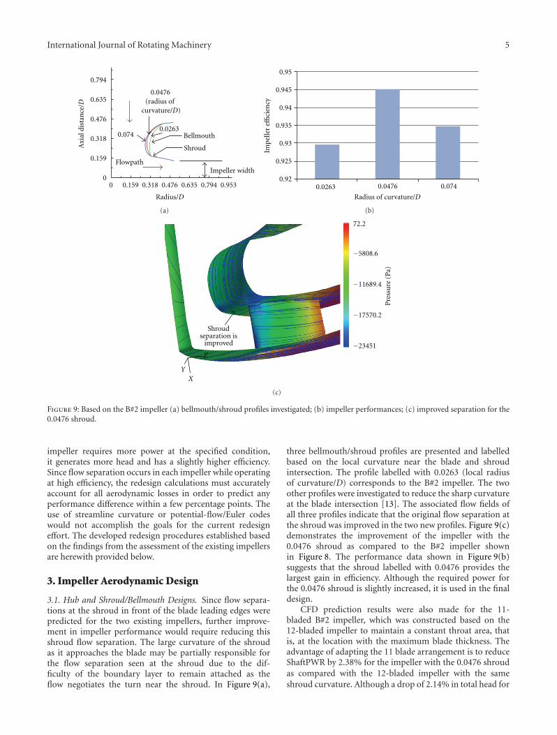
Figure 9: Based on the B#2 impeller (a) bellmouth/shroud profiles investigated; (b) impeller performances; (c) improved separation for the0.0476 shroud.
impeller requires more power at the specified condition,it generates more head and has a slightly higher efficiency.Since flow separation occurs in each impeller while operatingat high efficiency, the redesign calculations must accuratelyaccount for all aerodynamic losses in order to predict anyperformance difference within a few percentage points. Theuse of streamline curvature or potential-flow/Euler codeswould not accomplish the goals for the current redesigneffort. The developed redesign procedures established basedon the findings from the assessment of the existing impellersare herewith provided below.
3. Impeller Aerodynamic Design
3.1. Hub and Shroud/Bellmouth Designs. Since flow separa-tions at the shroud in front of the blade leading edges werepredicted for the two existing impellers, further improve-ment in impeller performance would require reducing thisshroud flow separation. The large curvature of the shroudas it approaches the blade may be partially responsible forthe flow separation seen at the shroud due to the dif-ficulty of the boundary layer to remain attached as theflow negotiates the turn near the shroud. In Figure 9(a),
three bellmouth/shroud profiles are presented and labelledbased on the local curvature near the blade and shroudintersection. The profile labelled with 0.0263 (local radiusof curvature/D) corresponds to the B#2 impeller. The twoother profiles were investigated to reduce the sharp curvatureat the blade intersection [13]. The associated flow fields ofall three profiles indicate that the original flow separation atthe shroud was improved in the two new profiles. Figure 9(c)demonstrates the improvement of the impeller with the0.0476 shroud as compared to the B#2 impeller shownin Figure 8. The performance data shown in Figure 9(b)suggests that the shroud labelled with 0.0476 provides thelargest gain in efficiency. Although the required power forthe 0.0476 shroud is slightly increased, it is used in the finaldesign.
CFD prediction results were also made for the 11-bladed B#2 impeller, which was constructed based on the12-bladed impeller to maintain a constant throat area, thatis, at the location with the maximum blade thickness. Theadvantage of adapting the 11 blade arrangement is to reduceShaftPWR by 2.38% for the impeller with the 0.0476 shroudas compared with the 12-bladed impeller with the sameshroud curvature. Although a drop of 2.14% in total head for

6 International Journal of Rotating Machinery
Objectives:
ShaftPWR and
ImpPWRout
Design parameters
Fitness values
Gridgen
and SCULPTOR
GA
Design grids are created based on
ASD grid
Designs from previous generations are saved in parametric space and their flow solutions
used as initial guess
CRUNCH CFD
Figure 10: Flowchart for blade optimization.
the latter impeller occurred, the efficiency was maintained.These results led to the decision to choose the 11-bladed0.0476 shroud profile impeller configuration. In addition,this modification required a blade redesign to recover thedrop in the total head.
3.2. 2D Blade Profile Optimization. A GA-based procedurewas used for optimization of the impeller blade. Since im-peller B#2’s blade performs better than the B#1 impelleras shown in the last section, the B#2 blade shape wasused as the starting geometry and all changes to the bladeshapes were made through a network of Bezier curves. TheGA uses the traditional selection, crossover, and mutationoperators, whose implementation details are provided in[14]. A schematic of the design optimization framework isshown in Figure 10. Variables that represent deformation ofthe blade shape by moving the control points were passed bythe GA to SCULPTOR where the shape modifications andgrid alterations were performed. The grids were then passedto CRUNCH CFD and the performance of the altered designswas evaluated. The performance metrics in the form of theobjective functions were passed back to the GA for the nextdesign iteration.
The blade shapes were defined by a complex networkcontrol points which form an arbitrary shape deformation(ASD) grid (Figure 11(a)) that was generated utilizing theSCULPTOR tool. The blade shape was parameterized by10 design variables of 5 control points (5 design variableson the pressure side and 5 design variables on the suctionside shown in Figures 11(b) and 11(c)). The grouping ofcontrol points was implemented in the spanwise directionto ensure that the integrity of the 2D shape was maintained.GRIDGEN was used to generate the initial CFD grid for theoriginal blade shape and subsequent grids were automaticallygenerated with shape deformation propagating through thegrids. The deformation was performed on a 2D airfoil shapeand maintained along the spanwise direction. Furthermorethe deformation was propagated to the grid points of the
CFD grid associated with the newly deformed blade shapewithin SCULPTOR.
The design requirements called for improving the effi-ciency of lift fan while meeting the set design criteria for theoutput fluid power delivered by the impeller. Conventionally,design optimization can be carried out for such a problemby either performing a multiobjective optimization or byusing constraints to limit the shaft power and to maximizethe output power. We utilized a mathematical function thatwas a combination of a target efficiency (95%) and a targetpower requirement as an objective function. CRUNCH CFDcalculated flow parameters as presented in (4)–(6). Theobjective of the GA was to measure the distance from a targetShaftPWR and output power, that is,
dobj =√
(ShaftPWR− 581)2 +(ImpPWRout − 552
)2
PWRref. (7)
For this case, the targeted ShaftPWR and output powerwere set at 581 and 552 kWs, respectively. The objectivefunction was set to compare impeller B#1’s performance dataof 603.3 and 558.5 kWs, which has an impeller efficiency of92.6% as described previously. The optimization calculationwas to minimize this objective function. Due to the timeconstraint during the design phase, a total of 48 designswere analyzed during the design iterations. In Figure 12, theimpeller total head generated and efficiency associated witheach blade design during the 6 generation calculations areplotted in black diamond symbols versus the shaft power.The impeller head is nearly linear in relationship to the shaftpower. The shaft power values for the B#1 impeller and thedesign power threshold of 4.7% and goal of 10% reductionare also marked in each plot. The selected 2D blade shape,circled in the solid black circle in Figure 12, has a near peakfitness value plotted in Figure 13 and the highest efficiencyin Figure 12 among all GA designs. The fitness plot inFigure 13 is an inverse measurement of the defined objectivefunction shown in (7). The final unconventional 2D designfrom the GA design iteration is shown in Figure 14. Theincreased loading of the blade near midchord resulted in flowacceleration especially near the shroud where the originalblades were prone to a large area of flow separation. Thisblade shape generated a total head of 1.459 Pref at 93.68%efficiency and requires a shaft power of 0.926 PWRref . Somesmall modifications were made to the 2D blade through asteering process followed by the construction of a 3D bladeby sweeping the 2D sections. The steering process and 3Dblade construction is discussed in the following sections. Theprediction results for all these later modifications are alsoplotted in Figures 12 and 13 as “Non-GA” points. After thefinal 3D modification, the fitness and efficiency are furtherimproved from those obtained for the 2D blade design byGA. The peak of the “Non-GA” points in Figure 13 was notselected due to the aggressiveness of the design which will bedescribed in the next section.
3.3. Steering of Blade Shape. The 2D blade cross-section de-sign described in the previous section was performed in arelatively conservative manner due to an “unknown” cou-

International Journal of Rotating Machinery 7
ASD grid
CFD grid
(a)
(b) (c)
ASD chordwise grid
Control points
Figure 11: Blade design parameters are defined with ASD grid (a) a 3D view; (b) a chordwise view with a deformed blade; (c) a close-upview at the trailing-edge region of the deformed blade.
1.6
1.5
1.4
1.30.8 0.84 0.88 0.92 0.96 1
Impe
ller
tota
lpre
ssu
re/P
ref
ShaftPWR/PWRref
GA-gen6Non-GA
10% (0.852)
4.7% (0.902)
B#1 (0.945)
(a)
10% (0.852)
4.7% (0.902)B#1 (0.945)
96
94
92
90
Imp
elle
reffi
cien
cy
0.8 0.84 0.88 0.92 0.96 1
ShaftPWR/PWRref
GA-gen6Non-GA
(b)
Figure 12: Landscape of optimization process in total pressure and efficiency versus ShaftPWR (black solid circle indicates result obtainedfrom 2D design, blue dash circle is from 2D steering, and red dash-dot circle is from 3D design).
pling effect from the downstream volute. In addition, theperiod of the design phase was limited. In order to furtherenhance the gain in reducing the shaft power, a trailing-edge modification was adapted. Since the blade trailing edgesare placed at the maximum velocity region of the entire fanflow field, the effect of modifying the trailing-edge shape canbe dramatic. Figure 15 demonstrates two steering profiles,
that is, steer blade-1 and steer blade, with minor changes intheir trailing-edge profiles (i.e., trailing-edge angle to reduceblade turning) from the 2D design blade. The calculated shaftpower, total head, and efficiency are 0.870 PWRref , 1.376 Pref ,and 93.87% for the steer blade-1; 0.896 PWRref , 1.414 Pref ,and 93.8% for the steer blade. The impeller efficiencies of thetwo steer blades and the 2D design blade are almost identical.

8 International Journal of Rotating Machinery
0.8 0.84 0.88 0.92 0.96 1
ShaftPWR/PWRref
GA-gen6Non-GA
400
300
200
100
0
Fitn
ess
10% (0.852)
4.7% (0.902) B#1 (0.945)
Figure 13: Fitness versus shaft power during design calculations.
OriginalB#2 blade
New 2D design blade
Figure 14: Blade shape obtained from 2D blade design optimiza-tion.
Even though the steer blade-1 required much lower shaftpower, it unfortunately delivered much less head and outputpower. The steer blade-1 was considered too aggressive inmeeting the requirement; therefore, the more conservativesteer blade was chosen for further investigation.
3.4. 3D Swept Blade Design. Both existing impeller’s bladeswere primarily 2D blades, that is, the leading and trailingedges at hub and shroud started at the same radii. The bladewas designed as a 2D blade to reduce the manufacturingcost. There are some advantages to sweeping the blade: (i)a blade starting at a lower radius near the shroud can preventboundary-layer separation by accelerating the flow before itactually turns, and (ii) it changes in incidence at the leadingedge attributed to the sweep can lower losses and increaseefficiency. Based on this concept, the B#2 11-bladed impellerblades were extended inward radially at the leading edgeand its angle measured from the shroud was modified from0 degree for a 2D blade like the B#1 blade to 10 degrees.The new 3D blade generated high head of 1.548 Pref versus1.471 Pref with a higher efficiency of 95.08% versus 93.66%
Original B#2 blade
2D design blade
Steer blade-1
Steer blade
Figure 15: Blade shape obtained from 2D blade steering.
at the expense of a higher shaft power of 0.968 PWRref versus0.936 PWRref . This procedure essentially improves the bladeefficiency. When the same procedure was applied to the steerblade shown in Figure 15, the efficiency improved from 93.8to 95.55%, the head increased from 1.414 Pref to 1.459 Pref
with the shaft power also increasing from 0.896 PWRref to0.909 PWRref . From here on out, when this 3D version of thesteer blade is integrated with the impeller, it is referred to asthe NEW design impeller.
3.5. Impeller Width Control. Impeller width is defined inFigure 9 as the distance between the backplate and theshroud. It represents the blade trailing-edge span with theshroud terminating at the blade trailing edge. Given theimpeller diameter and the flow rate, this parameter controlsthe maximum achievable flow velocity. The widths for thetwo existing impellers shown in Figure 2 are 0.1207 D and0.1350 D, respectively.
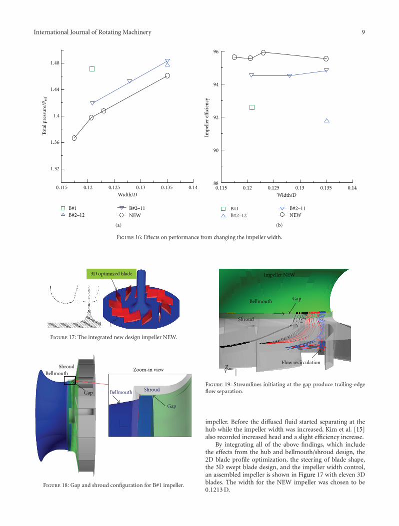
The width of the NEW impeller is determined by startingwith the B#2 impeller width. Figure 16 shows the effects ofthe total pressure generated and the efficiency when changingthe impeller width for the 11-bladed B#2 (B#2-11) impellerand the NEW impeller. Also shown in Figure 16 is theperformance data from the B#1 and B#2 impellers. Derivedfrom the B#2 blading, a nearly linear performance wasidentified for the predicted shaft power (shown in [13]) andtotal head. Unlike the other parameters mentioned above,the efficiency seems to be independent of the width change.By adjusting the impeller width, the impeller total pressurecan be controlled without sacrificing the performance. Inother words, the NEW impeller generates less total head withthe same width as the B#1 impeller; however, with increasedwidth, the NEW impeller is able to produce the same totalhead as the B#1 impeller. Conversely, for a fixed impellerwidth, altering the blade geometry can play an important rolein lowering shaft power and increasing impeller efficiency.
Similar improvement in the compressor performance byincreasing the volute inlet width was reported by Kim etal. [15]. It should be noted that the volute inlet width wasthe same as the impeller width in their study. Note thatthe current volute inlet has a sudden expansion (shownin Figure 3) from the impeller exit versus Kim’s volutewhich has a smooth connection between the volute and the
International Journal of Rotating Machinery 9
1.48
1.44
1.36
1.32
0.115 0.12 0.125 0.13 0.135 0.14
Tota
lpre
ssu
re/P
ref
Width/D
B#1B#2–12
B#2–11
NEW
1.4
(a)
Impe
ller
effici
ency
96
94
92
90
880.115 0.12 0.125 0.13 0.135 0.14
Width/D
B#1B#2–12
B#2–11NEW
(b)
Figure 16: Effects on performance from changing the impeller width.
3D optimized blade
Figure 17: The integrated new design impeller NEW.
Gap
GapShroud
Shroud
Bellmouth
BellmouthZoom-in view
Figure 18: Gap and shroud configuration for B#1 impeller.
Impeller NEW
Bellmouth Gap
Shroud
Flow recirculation
YZ
Figure 19: Streamlines initiating at the gap produce trailing-edgeflow separation.
impeller. Before the diffused fluid started separating at thehub while the impeller width was increased, Kim et al. [15]also recorded increased head and a slight efficiency increase.
By integrating all of the above findings, which includethe effects from the hub and bellmouth/shroud design, the2D blade profile optimization, the steering of blade shape,the 3D swept blade design, and the impeller width control,an assembled impeller is shown in Figure 17 with eleven 3Dblades. The width for the NEW impeller was chosen to be0.1213 D.

10 International Journal of Rotating Machinery
Flow measuring chamber
Lift exhaust duct Fan Thruster nozzle
Shaftmotor
Figure 20: Centrifugal fan test rig.
4. Prediction of Fan Performance
4.1. Computational Method for Fan Flow Field. In order toevaluate the fan performance, it is necessary to include thevolute with each impeller. Since the volute outer casing con-figuration is a structural constraint, it stays the same for allfans, the volute flow field and its feedback to the impeller aremodified for changes in the impeller exit conditions and thevolute-side’s bellmouth and shroud shapes.
The impeller flow field is unsteady and periodic due tothe interaction between each blade and the asymmetric vo-lute casing (Figure 2), particularly at the two tongue loca-tions. This time-varying flow field could be approximated bya time-averaged or steady flow field with a fixed geometricrelationship between the impeller and the volute. Thissimplification is referred to as the frozen impeller approach.It computes the entire (all blades included) impeller steadyflow field in the rotational frame and converts the flowfield information to a stationary frame at an interface nearthe impeller exit to the downstream volute. The steadynonrotating volute flow is calculated from the interfaceto each volute exit. The conditions at the interface serveas information exchange between the impeller and the voluteand are obtained as a part of the solution. The process isaccomplished by convergence of key quantities such as thetotal pressures and mass flow rates at the impeller inlet,interface, and volute outlets.
For the impeller-flow calculation, all boundary condi-tions used for the CFD design calculations were maintainedexcept for eliminating the periodic boundary condition andcontrolling the exit back pressure through the interfaceinformation exchange. For the volute-flow calculation, themass-averaged discharge pressures from the two exits areprescribed to keep (a) the required flow to the lift side, (b)the extended surface from the impeller backplate modelledas a symmetry plane, (c) the shroud as the rotating wall, and(d) all other casing surfaces as no-slip walls.
The fan performance parameters were evaluated dif-ferently from the impeller design calculation. The shaftpower was calculated using (4) while Timp was obtained byintegrating the torque from all the impeller blades. The fanoutput power and the total-to-total efficiency were calculatedusing the following formulae:
FanPWRout = [(ΔPt)lift ·Qlift + (ΔPt)thruster ·Qthruster], (8)
ηfan = FanPWRout
ShaftPWR. (9)
There are two other parameters related to the lift-sideperformance. They are lift-side total and static efficiencies,which were calculated as follows:
(ηt)
lift =(ΔPt)lift ·Qlift
ShaftPWR, (10)
(ηs)
lift =(ΔPs)lift ·Qlift
ShaftPWR. (11)
The grid topology used for the impeller design calcula-tion shown in Figure 5 was maintained. Depending on thenumber of blades designed for each fan, the total impellergrid was approximately 3 to 4 million cells. The correspond-ing volute for each fan had approximately 1.5 million cells.The converged volute solution for the baseline B#1 impellerwas first obtained by adjusting the pressures at the two exitsto reach the design lift flowrate. Similar exit pressures wereapplied for all other impeller calculations to obtain the liftflowrates shown in Tables 2 and 3.
4.2. Impeller/Volute Coupling Solutions. Table 2 shows theperformance data obtained from the impeller/volute cou-pling calculations for all fans. Adapted from the grid topol-ogy used for the impeller design CFD, the impeller gridended at a fixed radius for all coupling calculations exceptfor the NEW impeller, which ended at a slightly smallerradius. In order to compare the performance with similargrid features for all fans, the NEW-x grid was generatedby radially extending the shroud of the NEW impeller.Since the impeller width plays an essential role in theimpeller performance, a wider width impeller was generatedfor comparison and is labelled as the NEW-w impeller.
In addition, the fan total-to-total efficiency is calculatedin Table 2 using (8) and (9). The lift-side static and total pres-sures, along with their efficiencies are also tabulated. Thevolute losses (column “Loss”) at the lift side were estimatedby subtracting the lift-side total pressure from the impellerhead (del Pt).
It is interesting to note that the B#2 impeller now requiresless shaft power (0.8%) than the B#1 impeller. The NEWimpeller reduces shaft power by 5.76% from the baseline.When the volute was coupled with the impeller, the impellerefficiency for the NEW impeller dropped from the impeller-design prediction of 95.5% to 89%. Similar reductions werepredicted for the B#1 and B#2 impellers, that is, from 93%to 88%. A total drop of five to six percentage points in theimpeller efficiency with the volute feedback is considered.When the losses in the volute were included, the total fanefficiency further reduced to between 76.9% and 78.3% forall fans except the B#2 impeller which decreased to 74%. Thedramatic reduction in the volute loss for the NEW impeller

International Journal of Rotating Machinery 11
Ta
ble
2:Fa
np
erfo
rman
ceda
taob
tain
edfr
omim
pelle
r/vo
lute
cou
plin
gC
FD.
Fan
Shaf
tpo
wer
/PW
Rre
f
Imp
PW
Rou
t/P
WR
ref
del
Pt/P
ref
Eff
imp
(%)
Eff
fan
(%)
Wid
th/D
Ps
lift/P
ref
Pt
lift/P
ref
Loss
/Pre
fE
fflif
t(t
otal
)(%
)E
fflif
t(s
tati
c)(%
)L
ift
Flow
(%)
B#1
0.91
80.
812
1.36
688
.476
.90.
1208
1.18
71.
227
0.13
90.
451
0.43
756
.7B
#20.
911
0.80
81.
359
88.7
74.0
0.13
501.
092
1.14
20.
217
0.41
70.
399
55.9
NE
W0.
865
0.75
91.
278
87.8
76.9
0.12
131.
144
1.18
70.
091
0.46
10.
444
57.0
NE
W-x
0.86
50.
770
1.29
789
.078
.10.
1213
1.13
91.
182
0.11
50.
458
0.44
156
.5N
EW
-w0.
871
0.78
21.
315
89.8
78.3
0.12
371.
154
1.19
60.
119
0.46
00.
443
56.5

12 International Journal of Rotating Machinery
Lif
tpr
essu
reco
effici
ent
0.5
0.5
0.4
0.4
0.3
0.3
0.2
0.2
0.1
0.10
0Flow coefficient
Design
Impeller B#1
RequirementB#1 model test (5212 rpm)B#1 CFD (FS)B#1 CFD (MS)
(a)
Lift
pres
sure
coeffi
cien
t
0.5
0.5
0.4
0.4
0.3
0.3
0.2
0.2
0.1
0.10
0Flow coefficient
Design
Impeller B#2
RequirementB#2 model test (5212 rpm)B#2 CFD (FS)B#2 CFD (MS)
(b)
Design
Impeller NEWRequirementNEW model test (5212 rpm)NEW CFD (FS)NEW CFD (MS)
Lift
pres
sure
coeffi
cien
t
0.5
0.5
0.4
0.4
0.3
0.3
0.2
0.2
0.1
0.10
0Flow coefficient
(c)
Figure 21: Measured lift pressure coefficient compared with the requirement and CFD predictions for the B#1, B#2, and NEW impellers.
14
12
10
8
6
4
2
0
−2
−4
−6
Red
uct
ion
(%)
ShaftPWROutPWR
Lift PsLift PtVolute Loss
B#1 B#2 NEW
Fan Eff
Rey No Effect
Figure 22: Predicted impact of model fan’s lower Re number on fanperformance for the existing and new fans.
suggests that the exit flow from the new impeller matchesbetter with the downstream volute flow than those for theexisting impellers. In summary, the NEW impeller improvesfan efficiency by 1.2 percentage points and reduces power by5.8%.
Although the calculated static pressures are all higherthan the required lift-side discharge pressure (Ps/Pref > 1),the air static pressures at the lift side for both NEW and B#2
impellers are lower than that of the B#1 impeller. As shownin current predictions, the NEW impeller can meet the liftpressure and power reduction requirements if the existingB#1 impeller is overpowered at the design condition.
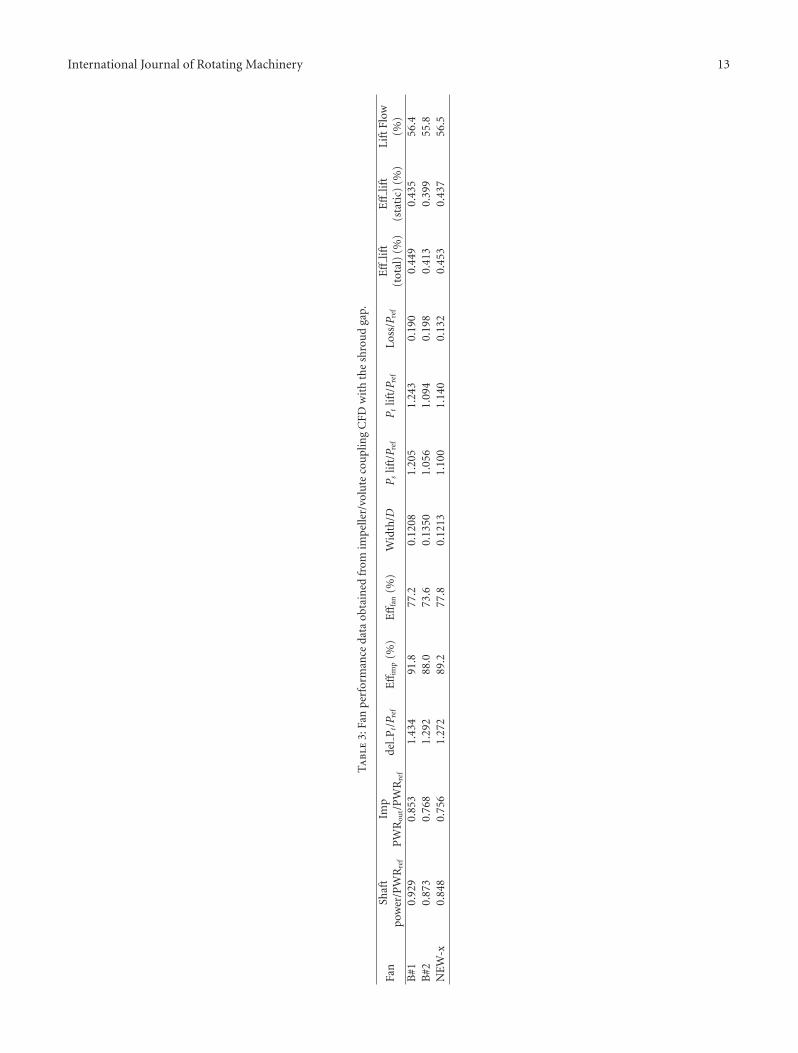
4.3. Impeller/Volute Coupling Solutions with Shroud Gap Ef-fect. The shroud gap between the stationary bellmouth andthe rotating shroud is shown in Figure 18 for the B#1 im-peller. Using this refined geometry, the frozen impellercalculations included not only the narrow gap, but alsothe shroud thickness and its end shape. The gap sizesdesigned for the B#1, B#2, and NEW impellers are 0.08%,0.15%, and 0.08% of the impeller diameter, respectively. Theshroud gap flow accounts for 0.52%, 0.92%, and 0.58% ofthe inflow at the design condition for the three impellers.Table 3 provides the performance data at the design con-dition for the three impellers. Reference [16] providesfurther details for the effects of the gap on the impelleraerodynamics.
Comparing the data between Tables 2 and 3, the gapeffect for the B#1 impeller inversely affects performanceas compared to the other two impellers. The B#2 andNEW impellers suffer about 0.5% reduction in fan effi-ciency due to the gap-affected impeller exit flow [17]into the volute which induces impeller blade trailing-edgeflow recirculation, as shown in Figure 19. In contrast, theshroud gap flow improves both the impeller and the fanefficiencies for the B#1 impeller. This may have been causedby the unstable gap-flow solution using the current steadycalculation procedure. The calculations including the gapfurther complicate the role of volute influences to the fan’soverall performance. Tabular data provided in Table 3 forthe B#2 and NEW impellers also indicate the shaft powersare reduced by 6.0% and 8.7%, respectively, as compared tothe B#1 impeller.
International Journal of Rotating Machinery 13
Ta
ble
3:Fa
np
erfo
rman
ceda
taob
tain
edfr
omim
pelle
r/vo
lute
cou
plin
gC
FDw
ith
the
shro
ud
gap.
Fan
Shaf
tpo
wer
/PW
Rre
f
Imp
PW
Rou
t/P
WR
ref
del
Pt/P r
efE
ffim
p(%
)E
fffa
n(%
)W
idth
/DPs
lift/P r
efPt
lift/P r
efLo
ss/P
ref
Eff
lift
(tot
al)
(%)
Eff
lift
(sta
tic)
(%)
Lif
tFl
ow(%
)B
#10.
929
0.85
31.
434
91.8
77.2
0.12
081.
205
1.24
30.
190
0.44
90.
435
56.4
B#2
0.87
30.
768
1.29
288
.073
.60.
1350
1.05
61.
094
0.19
80.
413
0.39
955
.8N
EW
-x0.
848
0.75
61.
272
89.2
77.8
0.12
131.
100
1.14
00.
132
0.45
30.
437
56.5

14 International Journal of Rotating Machinery
5. Design Validation through Model Fan Test
Test data for all three fans was collected from the 1/5-scalefan test rig as shown in Figure 20. The performance test set-up was constructed using the American National StandardsInstitute (ANSI)/Air Movement and Control Association(AMCA) standards [8] as a reference. For model Reynoldsnumber (Re) to be similar to the full-scale value, the modeltest would ideally be run at 5-times the full-scale speed of1692 rpm. Following the Re suggestion of Phelan et al. [18],Re based on U and D should be between 1.0 × 10⁶ for thebackward-swept centrifugal fans and 2.0 × 10⁶ for airfoil-bladed centrifugal fans to reach the Re independent regime.The current measurements were limited to a maximumimpeller speed of 5212 rpm. For this case, the Re at thismodel operating condition is 1.8 × 10⁶. The measuredlift-side static pressure coefficient versus the lift-side flowcoefficient is plotted in Figure 21 for the three impellers. Theuncertainty of the measured pressure was estimated to bewithin 0.25% [8] at design conditions. Comparisons shownin Figure 21 include the original design required pressurerise, model test data, and CFD predictions for the full-scale(FS) and model-scale (MS) fans. The latter calculations forthe MS fans were performed using the MS Re number, whichis about 12% of the FS Re number. There existed a suddenpressure drop in all three fans at the point the fans went intostall conditions. For the B#1 impeller, a sudden pressure riseexists near the design condition. This rise in pressure doesnot occur for the other two impellers. This phenomenonmay be attributed to the fan testing conditions being closeto the flow transition region, where separated and reattachedflows were interchanged to affect the sudden pressure riseand drop.
CFD predictions shown in Figure 21 for the FS and MSfans clearly demonstrate the Re effect, which is larger for theB#1 and B#2 impellers than the NEW impeller. CFD resultsalso include predictions using off-design flow rates. The MSCFD predictions agree well with the model test data for bothB#1 and NEW impellers, particularly the rise and fall for theNEW impeller. The CFD underpredicts the lift pressure forthe B#2 impeller which may have resulted from the deviationin geometry used for the calculations and the experiments.Figure 22 provides comparisons of the reductions in variousfan performance parameters obtained from the differencesbetween the MS and the FS fan calculations among threeimpellers. The NEW impeller has the smallest performancevariation in almost all the parameters predicted, particularlyfor the volute losses as pointed out previously.
Comparing the design requirement with the measureddata, it is obvious from Figure 21 that both impellers B#1and B#2 generate more-than-required pressure at the volutelift-side discharge. This verifies the conclusion obtained inthe previous section and confirms the feasibility of furtherreducing power consumption. Specifically, the measured lift-side pressures for the B#1, B#2, and NEW impellers are13.8%, 9.6%, and 3.7% higher than the required pressure(shown in (2)) at the design condition, respectively. Similarly,the measured power reductions for the three impellers at thedesign condition are 5.7%, 7.8%, and 14.0% lower than the
required power shown in (3), respectively. In other words,the B#2 and NEW impellers reduce the shaft power by 2.2%and 8.8%, respectively, in comparison with the B#1 impeller.The NEW impeller has achieved twice the amount of powerreduction from the baseline B#1 impeller and agrees wellwith the CFD predictions shown in the last section.
6. Summary and Conclusion
A double-inlet, double-width impeller was modified to fitinto a baseline double-discharge volute for a centrifugalfan. The goal was to reduce power consumption whilemaintaining a specified output pressure at the lift-side voluteexit. The design modification was completed by decouplingthe impeller from the volute. Using the developed designstrategy, the following results are identified.
(i) The impeller-only calculations for the baseline B#1impeller and the reference B#2 impeller indicate thatthe total efficiencies of both existing impellers arehigh (above 92%). This suggests that conventionaldesign methods such as a streamline curvature oran inviscid calculation method would be inadequatein addressing any aerodynamic improvements tothe existing impellers. In addition, a computationalmethod accounting for all the aerodynamic losses isrequired.
(ii) The flow turning area from the axial to the radialdirection in front of the blade leading edge is requiredto be adequately designed to avoid the shroud flowseparation. A blade leading-edge extension and sweepinto the shroud turning area prevents the air fromseparating from the shroud surface and improvesthe impeller’s efficiency. This allows the 14-bladedbaseline B#1 impeller to be redesigned as the 11-bladed NEW impeller.
(iii) The 2D blade profile optimization, based on anumerical coupling between a CFD calculation anda genetic algorithm optimization scheme, is ableto achieve a composite objective with a projectedshaft power and a power output. The optimizationimproves the impeller efficiency from 92.6% to93.7%.
(iv) Blade trailing-edge shape control (or blade steering)effectively modifies the impeller exit flow and reducespower (from 0.945 to 0.896 PWRref or a 31.3 kWreduction) while maintaining efficiency.
(v) The width of the impeller is almost linearly relatedto the impeller total head generated. However, theimpeller efficiency remains nearly constant while thewidth changes.
The CFD calculations for evaluating the fan performancewere performed using a frozen impeller approach to computethe steady flows throughout the impeller and the volute.CFD predictions were validated with the measurements. Theconclusions drawn from the comparisons are as follows.

International Journal of Rotating Machinery 15
(i) Volute feedback to the impeller reduces impellerefficiency by five to six percentage points fromthe original range of 93–95%. Fan efficiency isfurther reduced to the 74–78% range by includingthe volute losses. The matching volute design plays animportant role in determining fan efficiency, which isimproved by 1.2% for the new fan over the baselinefan.
(ii) The shroud gap between the bellmouth and theshroud carries less than 1% of the inflow back fromthe volute to the impeller for the current fans. Italso reduces fan efficiency by 0.5%. Although the gapflow alleviates the shroud flow separation, it affectsthe blade trailing-edge flow, particularly at the volutetongue locations.
(iii) The test data of the lift-side pressure rise for theexisting and new impellers agrees well with the CFDpredictions based on the model Reynolds number.The CFD predictions suggest that a Reynolds numbereffect exists between the model- and full-scale fans.This Reynolds number effect is larger for the existingimpellers as compared to the new impeller.
(iv) The comparisons between the CFD predictions andmeasurements confirm that the existing fan wasoverpowered at design, which enabled a new impellerdesign with a lower power requirement. The mea-sured power reduction for the new impeller is 8.8%lower than the baseline. This reduction in poweragrees with the 8.7% reduction obtained from theCFD predictions.
Disclosure
This material is declared a work of the U.S. Government andis not subject to copyright protection in the United States.Approved for public release; distribution is unlimited.
Abbreviations
ASD: Arbitrary shape deformationCRUNCH: CFD code used in the present studyD: Impeller diameter, 1.6 mDDV: Double discharge volutedobj: Distance parameter used in defining the
optimization objective function shownin (7)
DWDI: Double-width, double-inlet fan typeFS: Full scaleFan PWRout: Fan output power defined in (8)GA: Genetic algorithmImp PWRout: Impeller output power defined in (5)k: Turbulent kinetic energyB#1, B#2: Baseline and reference impellersMS: Model scaleNEW: New impellerP: Pressure
Pref : Reference pressure, 7517 PaQ: Flow rateRe: Reynolds numberShaftPWR: Shaft powerPWRref : Reference power, 638.3 kWt: TimeT: Impeller torqueU : Fan tip speed (141.77 m/s@design
condition)Uo: Inlet velocityu,v,w: Fluid velocity componentsx, y, z: Cartesian coordinate systemε: Turbulent dissipationη: Total efficiencyρ: Air densityω: Impeller rotating speed.
Subscripts
thruster: Thruster side of the fanimp: Impellerlift: Lift side of the fanout: Outputs: Static pressuret: Total pressure.
Acknowledgments
This paper was funded by the Office of Naval Research,Code 331 as part of the lift-fan efforts of the Seabase-to-Shore FNC Program. The ONR Program Manager was Dr.Ki-Han Kim. This paper was prepared under the supportof the Applied Research Program of the Office of NavalResearch administered at the Naval Surface Warfare Center,Carderock Division under the IAR Program. The com-putational resources from the Naval Oceanographic OfficeMajor Shared Resource Center (NAVOCEANO MSRC) wereprovided through the DoD High Performance ComputingModernization Program (HPCMP).
References
[1] L. Yun and A. Bliault, Theory and Design of Air Cushion Craft,Elsevier Butterworth-Heinemann 30 Corporate Drive, Bur-lington, Mass, USA, 2005.
[2] K. A. Kaupert and T. Staubli, “The unsteady pressure field ina high specific speed centrifugal pump impeller—part I: influ-ence of the volute,” Journal of Fluids Engineering, Transactionsof the ASME, vol. 121, no. 3, pp. 621–626, 1999.
[3] K. Hillewaert and R. A. Van Den Braembussche, “Numericalsimulation of impeller-volute interaction in centrifugal com-pressors,” Journal of Turbomachinery, vol. 121, no. 3, pp. 603–608, 1999.
[4] Y. T. Lee and T. W. Bein, “Performance evaluation of an air-conditioning compressor—part II: volute flow predictions,”International Journal of Rotating Machinery, vol. 5, no. 4, pp.241–250, 1999.

16 International Journal of Rotating Machinery
[5] T. Meakhail and S. O. Park, “A study of impeller-diffuser-volute interaction in centrifugal fan,” Journal of Turbomachin-ery, vol. 127, no. 1, pp. 84–90, 2005.
[6] A. Atif, S. Benmansour, and G. Bois, “Numerical investigationof velocity flow field inside an impeller air model of a centrifu-gal pump with vaned diffuser interactions and comparisonwith PIV measurements,” International Journal of RotatingMachinery, vol. 2010, Article ID 706043, 12 pages, 2010.
[7] K. V. Karanth and N. Y. Sharma, “CFD analysis on the effectof radial gap on impeller-diffuser flow interaction as well ason the flow characteristics of a centrifugal fan,” InternationalJournal of Rotating Machinery, vol. 2009, Article ID 293508, 8pages, 2009.
[8] M. E. Slipper, P. J. McGinnis, G. Choi et al., “Design andevaluation of high performance lift fan models for the landingcraft, air cushion (LCAC),” Naval Surface Warfare CenterReport NSWCCD-98-TR-2008, 2008.
[9] A. Hosangadi, R. A. Lee, B. J. York, N. Sinha, and S. M. Dash,“Upwind unstructured scheme for three-dimensiona com-busting flows,” Journal of Propulsion and Power, vol. 12, no.3, pp. 494–502, 1996.
[10] A. Hosangadi, R. A. Lee, P. A. Cavallo, N. Sinha, and B. J. York,“Hybrid, viscous, unstructured mesh solver for propulsiveapplications,” in Proceedings of the 34th Joint PropulsionConference, AIAA-98-3153, Cleveland, Ohio, USA, 1998.
[11] T. J. Barth, “A 3D upwind euler solver for unstructuredmeshes,” Paper No. AIAA-91-1548, 1991.
[12] T. J. Barth and S. W. Linton, “An unstructured mesh newtonsolution for compressible fluid flow and its parallel implemen-tation,” Paper No. AIAA-95-0221, 1995.
[13] Y. T. Lee, L. Mulvihill, R. Coleman et al., “LCAC lift fanredesign and CFD evaluation,” Naval Surface Warfare CenterReport NSWCCD-50-TR-2007/031, 2007.
[14] Y. T. Lee, V. Ahuja, A. Hosangadi, and M. Ebert, “Shapeoptimization of a multi-element foil using an evolutionaryalgorithm,” Transactions of the ASME Journal of Fluids Engi-neering, vol. 132, no. 5, pp. 051401-1–051401-11, 2010.
[15] S. Kim, J. Park, K. Ahn, and J. Baek, “Improvement of theperformance of a centrifugal compressor by modifying thevolute inlet,” ASME Journal of Fluids Engineering, vol. 132, pp.091101-1–091101-7, 2010.
[16] Y. T. Lee, “Impact of fan gap flow on the centrifugalimpeller aerodynamics,” Transaction of ASME Journal of FluidsEngineering, vol. 132, pp. 091103-1–091103-9, 2010.
[17] A. Hildebrandt and M. Genrup, “Numerical investigation ofthe effect of different back sweep angle and exducer width onthe impeller outlet flow pattern of a centrifugal compressorwith vaneless diffuser,” Journal of Turbomachinery, vol. 129,no. 2, pp. 421–433, 2007.
[18] J. J. Phelan, S. H. Russel, and W. C. Zeluff, “A study ofthe influence of reynolds number on the performance ofcentrifugal fans,” ASME Paper No. 78-WA/PTC-1, 1978.

International Journal of
AerospaceEngineeringHindawi Publishing Corporationhttp://www.hindawi.com Volume 2010
RoboticsJournal of
Hindawi Publishing Corporationhttp://www.hindawi.com Volume 2014
Hindawi Publishing Corporationhttp://www.hindawi.com Volume 2014
Active and Passive Electronic Components
Control Scienceand Engineering
Journal of
Hindawi Publishing Corporationhttp://www.hindawi.com Volume 2014
International Journal of
RotatingMachinery
Hindawi Publishing Corporationhttp://www.hindawi.com Volume 2014
Hindawi Publishing Corporation http://www.hindawi.com
Journal ofEngineeringVolume 2014
Submit your manuscripts athttp://www.hindawi.com
VLSI Design
Hindawi Publishing Corporationhttp://www.hindawi.com Volume 2014
Hindawi Publishing Corporationhttp://www.hindawi.com Volume 2014
Shock and Vibration
Hindawi Publishing Corporationhttp://www.hindawi.com Volume 2014
Civil EngineeringAdvances in
Acoustics and VibrationAdvances in
Hindawi Publishing Corporationhttp://www.hindawi.com Volume 2014
Hindawi Publishing Corporationhttp://www.hindawi.com Volume 2014
Electrical and Computer Engineering
Journal of
Advances inOptoElectronics
Hindawi Publishing Corporation http://www.hindawi.com
Volume 2014
The Scientific World JournalHindawi Publishing Corporation http://www.hindawi.com Volume 2014
SensorsJournal of
Hindawi Publishing Corporationhttp://www.hindawi.com Volume 2014
Modelling & Simulation in EngineeringHindawi Publishing Corporation http://www.hindawi.com Volume 2014
Hindawi Publishing Corporationhttp://www.hindawi.com Volume 2014
Chemical EngineeringInternational Journal of Antennas and
Propagation
International Journal of
Hindawi Publishing Corporationhttp://www.hindawi.com Volume 2014
Hindawi Publishing Corporationhttp://www.hindawi.com Volume 2014
Navigation and Observation
International Journal of
Hindawi Publishing Corporationhttp://www.hindawi.com Volume 2014
DistributedSensor Networks
International Journal of