pressure jet boilers - ideal commercial · pdf filethe falcon gts range of cast iron sectional...
TRANSCRIPT

Pressure Jet BoilersPressure Jet Range
www.idealcommercialheating.com
Com
mercial H
eating Solutions

Contents
Pressure Jet Boilers
4 Introduction
5-7 Buccaneer GTE (21 - 39 kW)
8-10 Falcon GTS (40 - 100 kW)
11-13 Harrier GTS (105 - 330 kW)
14-17 Viceroy GTS (300 - 780 kW)
18-20 Viscount GTS (754 - 1450 kW)
21-28 Vanguard L (130 - 3500 kW)
29-31 Product Specification
32-35 System Requirements
Ideal Service & Support, Training
37 Ideal Service & Support
38-39 Training at Ideal Heating
03
Introduction - Ideal Commercial & Industrial
Pioneering heatingsolutions since 1905
Here at Ideal, we understand that you want a
reliable, long term partner that has the skills
and expertise to deliver you a wide range of
reliable and pragmatic solutions.
With over 100 years of manufacturing
experience, you can be confident to know that
our capabilities stretch beyond traditional
boiler technologies Ideal Commercial Heating
provides a range of condensing solutions
both wall hung or floor mounted, all perfectly
designed to meet your individual building
requirements.
As well as being able to help you rise to the
challenge of the UK building regulations,
we also provide a dedicated support service
throughout the design, planning and after
sales stages, giving you total peace of mind
that we will provide you with the complete
one-stop solution, all from one manufacturer.
When you choose to partner with Ideal
you can be confident to know that you’re
partnering with a British manufacturer that’s
supported by a dedicated national service
team, delivering help and advice to you and
your customers throughout the year.
We have been keeping British buildings
warm for over a century and believe in
making products which are reliable, energy
efficient and easy to use, combining the
latest technology with common sense
engineering that make our products easy to
specify, simple to install & maintain and most
importantly are reliable.

Commercial Heating Solutions
Pressure Jet Range
Ideal Commercial Heating boasts the widest range of Pressure Jet boilers which provide outputs from
21 kW to 3500 kW giving the customer a boiler for all situations. They are designed to be compact in size
yet extremely powerful and efficient in performance, meeting all requirements at both full load and part
load for low emissions and high operating efficiency (90-93% net efficiency).
All models are suitable for gas or oil firing, whilst dual fuel options can be provided on selected models
only. Matched burners can be supplied together with modulating or low NOx options. Control panels are
provided with comprehensive features giving simple and robust operation.
The cast iron range from 21 kW to 1450 kW is designed to obtain the largest heat exchange surface in the
most space efficient size, yet maintain long life and easy servicing. Low modulated temperature operation
down to 40˚C allows more fuel savings.
The Vanguard L range of steel boilers from 130 kW to 3500 kW provides an increased range of outputs,
with careful combustion chamber and flue tube design for robust long life. The compact, reverse flame
design is one of the narrowest available making access easier.
All boilers have thick fibreglass insulation to minimise standing losses, and installation is simple with
‘either hand’ burner door hinging and easy access to all connections.
The Pressure Jet range comprises two categories:
Cast IronBuccaneer GTE 21 kW - 39 kW
Falcon GTS 40 kW - 100 kW
Harrier GTS 105 kW - 330 kW
Viceroy GTS 300 kW - 780 kW
Viscount GTS 754 kW - 1450 kW
SteelVanguard L 130 kW - 3500 kW
The Ideal Pressure Jet range - optimum power and optimum performance.
04 05
Pressure Jet
Introduction
Pressure Jet Boilers
Buccaneer GTE boilers are fully automatically controlled floor standing boilers designed for connecting to a
flue pipe and require a separate automatic fuel oil or gas burner.
The boilers are suitable for: combined indirect
pumped domestic hot water and central heating
systems; independent indirect pumped domestic
hot water or central heating systems.
Controls give the option to control two heating
zones and included as standard. Fully pumped
systems may be open vented or sealed.
Buccaneer GTE 21 - 39 kW
Buccaneer GTE 21 - 39 kW

Features and Benefits
• High efficiency (full and part load)
• Minimal emissions
• 3 pass cast iron heat exchanger
• Compact size
Commercial Heating Solutions
06 07
Pressure Jet
• Easy to install and service
• Low temperature return
• ‘Building Regulations L2’ Compliant
Model GTE 4 GTE 5 GTE 6
No. of Sections 4 5 6
Maximum Heat OutputkW 27 33 39
Btu/h x 103 92.1 112.6 133.1
Minimum Heat OutputkW 21 27 33
Btu/h x 103 71.7 92.1 112.6
Boiler Water Contentl 24.5 30 35.5
gal 5.4 6.6 7.8
Hydraulic Resistance at 11Kmbar 5.3 7.9 10.9
in.w.g. 2.1 3.2 4.4
Hydraulic Resistance at 20Kmbar 1.6 2.4 3.3
in.w.g. 0.6 1.0 1.3
Combustion Chamber Resistancembar 0.23 0.23 0.22
in.w.g. 0.01 0.01 0.01
Boiler DRY Weight Less Burner Unitkg 182 210 237.5
lb 401.5 463 523.5
Gas Firing Data
Maximum Gas Ratem3/h 3.10 3.79 4.47
ft3/h 109.4 133.8 158.1
Maximum Flue Gas Volumem3/sec 0.019 0.026 0.027
ft3/min 40 49 57
Maximum Flue Gas Temperature 9% CO2 at 180°C 190°C 190°C
Seasonal Efficiency % 85.51 84.68 84.18
Oil Firing Data
Maximum Oil Ratel/h 3.11 3.8 4.49
gal/h 0.69 0.84 0.99
Maximum Flue Gas Volumem3/sec 0.017 0.022 0.025
ft3/min 36 47 53
Maximum Flue Gas Temperature 12% CO2 at 180°C 190°C 190°C
Seasonal Efficiency % 88.90 88.10 87.60
Minimum Flow Rates
Normal Water Flow Rate Temperature l/s 0.586 0.717 0.847
Difference 11°C (20°F) gal/min 7.74 9.46 11.18
Mimimun Water Flow Rate Temperature l/s 0.184 0.225 0.266
Difference 35°C (63°F) gal/min 2.43 2.97 3.51
All temperatures are above ambient. Note: Fuel rates and flue gas data relate to maximum output ratings. Gas firing data relates to the use ofNATURAL GAS ONLY. Details for the use of LPG are available on request from Ideal Commercial Heating. The gas rate at calorific valuesdiffering from the standard quoted above may be calculated by direct proportion CALORIFIC VALUE: 38.5 MJ/m3 (1,035 Btu/ft3).
General data
Boiler dimensions and clearances
GTE Boiler Size GTE 4 GTE 5 GTE 6
Dimension B 692 819 946
Dimension C 812 939 1066
Dimension D 125 125 153
Dimension E 427 554 681
Dimension F 50 50 99
Boiler clearances
Boiler Model Front Back Left Right
Buccaneer GTE All 1000 500 500 500
1 Heating supply R 11⁄4
2 Heating return R 11⁄4
3 Drain cock (connection for pipe ø int. 14mm)
4 Flue spigot OD, ø 125
All dimensions in millimetres unless otherwise stated
Buccaneer GTE 21 - 39 kW

The Falcon GTS range of cast iron sectional pressure jet boilers offer high efficiency operation, ease of
maintenance, fuel flexibility and low emissions in a compact package. Suitable for oil or gas operation the
Falcon GTS is supplied in a choice of 5 standard models, rated in outputs from 40 kW to 100 kW the range
has a maximum operating pressure of 4 bar. The GTS 7 and GTS 8 may be high/low operation.
Designed with a large combustion chamber and 3 pass,
horizontal flue way incorporating fins and cast iron
turbulators, the Falcon GTS ensures maximum heat
transfer efficiency.
The boilers are suitable for combined indirect
pumped domestic hot water, central heating
systems, independent indirect pumped domestic
hot water and central heating systems.
Fully pumped systems may be open vented
or sealed.
Falcon GTS 40 - 100 kW
08
Pressure Jet
Pressure Jet Boilers
Falcon GTS 40 - 100 kW
09
Features and Benefits
• High efficiency (full and part load)
• 3 pass cast iron heat exchanger
• Compact size
• Comprehensive control including diagnostic display
• Easy to install and service
• Low temperature return
• ‘Building Regulations L2’ Compliant
General data
Model GTS 4 GTS 5 GTS 6 GTS 7 GTS 8
No. of Sections 4 5 6 7 8
Maximum Heat OutputkW 50 64 78 92 100
Btu/h x 103 170 218 266 314 341
Minimum Heat OutputkW 40 50 64 78 92
Btu/h x 103 136 170 218 266 314
Boiler Water Contentl 36 43 50 57 64
gal 7.9 9.5 11 12.5 14.1
Hydraulic Resistance at 11Kmbar 20.3 33.3 49.3 68.4 84.0
in.w.g. 8.1 13.3 19.7 27.4 33.6
Hydraulic Resistance at 20Kmbar 6.1 10.1 14.9 20.7 25.4
in.w.g. 2.5 4.0 6.0 8.3 10.2
Combustion Chamber Resistancembar 0.5 0.6 0.8 0.8 0.9
in.w.g. 0.2 0.24 0.32 0.32 0.36
Boiler DRY Weight Less Burner Unitkg 254 296 344 381 423
lb 560 652 758 839 932
Gas Firing Data
Maximum Gas Ratem3/h 5.64 7.20 8.75 10.34 11.25
ft3/h 198.6 254 308.8 364.7 396.9
Maximum Flue Gas Volumem3/sec 0.031 0.04 0.048 0.058 0.064
ft3/min 66 84 103 124 135
Maximum Flue Gas Temperature 9% CO2 at 200°C 200°C 200°C 200°C 200°C
Seasonal Efficiency % 84.37 84.54 84.79 84.77 84.83
Oil Firing Data
Maximum Oil Ratel/h 5.65 7.22 8.78 10.37 11.25
gal/h 1.24 1.59 1.93 2.28 2.48
Maximum Flue Gas Volumem3/sec 0.030 0.039 0.047 0.059 0.062
ft3/min 65 83 100 125 131
Maximum Flue Gas Temperature 12% CO2 at 200°C 200°C 200°C 200°C 200°C
Seasonal Efficiency % 87.70 87.90 88.20 88.20 88.20
Minimum Flow Rates
Normal Water Flow Rate Temperature l/s 1.09 1.39 1.69 2.00 2.21
Difference 11°C (20°F) gal/min 14.4 18.4 22.3 26.4 29.2
Mimimun Water Flow Rate Temperature l/s 0.34 0.44 0.53 0.63 0.70
Difference 35°C (63°F) gal/min 4.5 5.8 7.0 8.3 9.3
All temperatures are above ambient. Note: Fuel rates and flue gas data relate to maximum output ratings. Gas firing data relates to the use of NATURALGAS ONLY. Details for the use of LPG are available on request from Ideal Commercial Heaing. The gas rate at calorific values differing from the standardquoted above may be calculated by direct proportion CALORIFIC VALUE: 38.5 MJ/m3 (1,035 Btu/ft3).
Commercial Heating Solutions

10
Boiler dimensions and clearances
1065
330 35 (1)
310
45º
6
5
B
E
= =2 3
702
555 115
136
1
194141
4
A
56
51
56
520
FAL8519
GTS Boiler Size GTS 4 GTS 5 GTS 6 GTS 7 GTS 8
Dimension A 700 827 954 1081 1208
Dimension B 772 899 1026 1153 1280
Dimension 4 153 153 180 180 180
Dimension 1-2 R 11⁄4 R 11⁄4 R 11⁄2 R 11⁄2 R 11⁄2
Dimension E 380 507 634 761 888
Boiler clearances
Boiler Model Front Back Left Right
Falcon GTS All 1000 500 500 500
1 Heating outlet
2 Heating return
3 Drainage / filling orifice Rp 3/4
4 Flue gas spigot
5 4xM8 on ø 150 and 4 markings on ø 170
6 Drilling ø 110 - Precut ø 130
(1) Adjustable feet: basic height 50mm with 35 to 65mm adjustment range.
All dimensions in millimetres unless otherwise stated
11
Commercial Heating Solutions
Pressure Jet Boilers
Harrier GTS boilers are cast iron sectional pressure jet boilers offering high efficiency operation, ease of
maintenance, fuel flexibility and low emissions.
Suitable for oil or gas operation the Harrier GTS range is supplied in a choice of 5 standard models, rated
in outputs from 105 kW to 330 kW and has a maximum operating pressure of 6 bar. All models may have
high/low operation.
Designed with a large combustion chamber,
3 pass horizontal flue ways, incorporating fins and
cast iron turbulators, the Harrier GTS ensures
maximum heat transfer efficiency (up to
91.5% nett).
The boilers are suitable for combined
indirect pumped domestic hot water and
central heating systems, independent
indirect pumped domestic hot water or
central heating systems.
Fully pumped systems may be open
vented or sealed.
Harrier GTS 105 - 330 kW
Harrier GTS 105 - 330 kW
Falcon GTS 40 - 100 kW

13
Pressure Jet
Harrier GTS 105 - 330 kW
12
Commercial Heating Solutions
Features and Benefits
• High efficiency (full and part load)
• Minimal emissions
• 3 pass cast iron heat exchanger
• Compact size
• Easy to install and service
• Low temperature return
• ‘Building Regulations L2’ Compliant
General data
Model GTS 5 GTS 6 GTS 7 GTS 8 GTS 9
No. of Sections 5 6 7 8 9
Maximum Heat OutputkW 140 180 230 280 330
Btu/h x 103 478 614 785 955 1126
Minimum Heat OutputkW 105 140 180 230 280
Btu/h x 103 358 478 614 785 955
Boiler Water Contentl 116 136 156 176 196
gal 25.5 29.9 34.3 38.7 43.1
Hydraulic Resistance at 11Kmbar 20.3 37.9 55.8 82.7 118.6
in.w.g. 8.1 15.2 22.3 33.1 47.5
Hydraulic Resistance at 20Kmbar 6.1 11.5 16.9 25.0 35.9
in.w.g. 2.5 4.6 6.8 10.0 14.4
Combustion Chamber Resistancembar 0.6 1.1 1.6 2.2 2.5
in.w.g. 0.24 0.44 0.64 0.88 1
Boiler DRY Weight Less Burner Unitkg 736 846 981 1103 1230
lb 1623 1865 2163 2432 2712
Gas Firing Data
Maximum Gas Ratem3/h 16.13 20.56 26.09 31.87 37.23
ft3/h 569 726 921 1125 1315
Maximum Flue Gas Volumem3/sec 0.092 0.117 0.149 0.182 0.213
ft3/min 196 249 316 386 452
Maximum Flue Gas Temperature 9% CO2 at 210°C 210°C 210°C 210°C 210°C
Seasonal Efficiency % 83.87 84.00 84.55 84.64 84.82
Oil Firing Data
Maximum Oil Ratel/h 15.52 19.76 25.10 30.66 35.81
gal/h 3.41 4.35 5.52 6.75 7.88
Maximum Flue Gas Volumem3/sec 0.090 0.114 0.145 0.178 0.208
ft3/min 191 242 308 376 440
Maximum Flue Gas Temperature 12% CO2 at 210°C 210°C 210°C 210°C 210°C
Seasonal Efficiency % 87.20 87.40 87.90 88.00 88.20
Minimum Flow Rates
Normal Water Flow Rate Temperature l/s 3.04 3.91 5.00 6.08 7.17
Difference 11°C (20°F) gal/min 40.1 51.6 66.0 80.2 94.6
Mimimun Water Flow Rate Temperature l/s 0.96 1.23 1.57 1.91 2.25
Difference 35°C (63°F) gal/min 12.7 16.2 20.7 25.2 29.7
All temperatures are above ambient. Note: Fuel rates and flue gas data relate to maximum output ratings. Gas firing data relates to the use of NATURALGAS ONLY. Details for the use of LPG are available on request from Ideal Commercial Heaing. The gas rate at calorific values differing from the standardquoted above may be calculated by direct proportion CALORIFIC VALUE: 38.5 MJ/m3 (1,035 Btu/ft3).
Boiler dimensions and clearances
1 017
827
1 37
1 15
B
OR
1192
137
387
H
105
CA
L
153D
800
53
98
153
195P103103 597
GTS Boiler Size GTS 5 GTS 6 GTS 7 GTS 8 GTS 9
Dimension A 130 130 130 130 130
Dimension B 105 105 105 105 105
Dimension C 165 165 165 165 165
Dimension D 738 738 738 738 738
Dimension H 1297 1297 1297 1297 1297
Dimension L 1151 1311 1471 1631 1791
Dimension P 650 810 970 1130 1290
Dimension Ø R 180 180 200 200 200
Boiler clearances
Boiler Model Front Back Left
Harrier GTS All 1500 1000
Door hinge side:500 or 200 +burner length.
Non hinge side: 100
All dimensions in millimetres unless otherwise stated

Viceroy GTS boilers are a range of cast iron sectional pressure jet boilers offering high efficiency operation,
ease of maintenance, fuel flexibility and low emissions.
Suitable for oil or gas operation the Viceroy GTS range is supplied in a choice of 7 standard models, rated
in outputs from 300 kW to 780 kW and has a maximum operating pressure of 6 bar.
All models have high/low operation.
Designed with a large combustion chamber,
3 pass horizontal flue ways, incorporating fins and
cast iron turbulators, the Viceroy GTS ensures
maximum heat transfer efficiency.
The boilers are suitable for combined indirect
pumped domestic hot water and central
heating systems, independent indirect
pumped domestic hot water or central
heating systems.
Fully pumped systems may be open
vented or sealed.
Viceroy GTS 300 - 780 kW
Pressure Jet Boilers
Viceroy GTS 300 - 780 kW
14 15
Commercial Heating SolutionsP
ressure Jet
Boiler assembly - sectional view
Control panel designed for easyaccess to wiring connections
Pocket forsensors ofthermostats
Hinged flue waycleaning doors(1 right handside and 1 lefthand side)
Fibreglasswool insulatedfront panel,60mm thick
Ceramic fibreinsulatedcleaning doors,80mm thick
Flame inspectionwindows (1 righthand side and 1left hand side)
Hinged burnerdoor (right handside or lefthand side)
Ceramic fibreinsulated burnerdoor, from 80 to140mm thick
Removableburner plate
Pre-cut casing allowingthe fitting of the quickopening valve Snap on burner connectors
compatible 2 stage, deliveredwith de luxe control paneland standard panel
Plug for optional drain cock
Insulation of the front panel:fibreglass wool 100mm thick
Silicon thermocordassuring flue gas tightness
Geometry of the front section very welladapted for the use of low NOx burners
Steel base frame
Completefibreglass woolinsulation,100mm thick
Water returnflange
Combustionchamberlargely sized
Eutectic castiron boiler bodywith 3 flue ways
Large flue wayswith fins andturbulatorsoffering a highefficiency andvery easymaintenance
Flue outlet with2 cleaning trapsaccessiblewithoutdismantling thecasing
Water flowflange
Pre-set flowswitch
2 large wiring ducts directlyaccessible under top casings
Cast ironturbulators
placed in theboiler flue ways
Eutectic cast iron boiler body,particularly resistant to thermal shocksand corrosion, allowing low modulatedtemperature operation and a total stopbetween 2 heating periods
Note: The view represents general boiler construction, jacket design and control panel will vary from that shown.
Pressure Jet
16
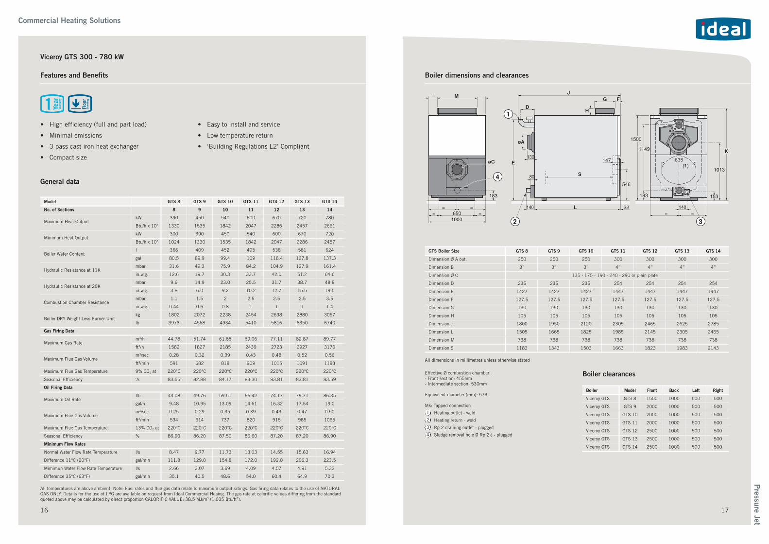
Boiler dimensions and clearances
GTS Boiler Size GTS 8 GTS 9 GTS 10 GTS 11 GTS 12 GTS 13 GTS 14
Dimension Ø A out. 250 250 250 300 300 300 300
Dimension B 3” 3” 3” 4” 4” 4” 4”
Dimension Ø C 135 - 175 - 190 - 240 - 290 or plain plate
Dimension D 235 235 235 254 254 254 254
Dimension E 1427 1427 1427 1447 1447 1447 1447
Dimension F 127.5 127.5 127.5 127.5 127.5 127.5 127.5
Dimension G 130 130 130 130 130 130 130
Dimension H 105 105 105 105 105 105 105
Dimension J 1800 1950 2120 2305 2465 2625 2785
Dimension L 1505 1665 1825 1985 2145 2305 2465
Dimension M 738 738 738 738 738 738 738
Dimension S 1183 1343 1503 1663 1823 1983 2143
Boiler clearances
Boiler Model Front Back Left Right
Viceroy GTS GTS 8 1500 1000 500 500
Viceroy GTS GTS 9 2000 1000 500 500
Viceroy GTS GTS 10 2000 1000 500 500
Viceroy GTS GTS 11 2000 1000 500 500
Viceroy GTS GTS 12 2500 1000 500 500
Viceroy GTS GTS 13 2500 1000 500 500
Viceroy GTS GTS 14 2500 1000 500 500
1 Heating outlet - weld
2 Heating return - weld
3 Rp 2 draining outlet - plugged
4 Sludge removal hole Ø Rp 21⁄2 - plugged
All dimensions in millimetres unless otherwise stated
Effective Ø combustion chamber:- Front section: 455mm- Intermediate section: 530mm
Equivalent diameter (mm): 573
Mk: Tapped connection
17
Commercial Heating Solutions
Viceroy GTS 300 - 780 kW
Features and Benefits
• High efficiency (full and part load)
• Minimal emissions
• 3 pass cast iron heat exchanger
• Compact size
• Easy to install and service
• Low temperature return
• ‘Building Regulations L2’ Compliant
General data
Model GTS 8 GTS 9 GTS 10 GTS 11 GTS 12 GTS 13 GTS 14
No. of Sections 8 9 10 11 12 13 14
Maximum Heat OutputkW 390 450 540 600 670 720 780
Btu/h x 103 1330 1535 1842 2047 2286 2457 2661
Minimum Heat OutputkW 300 390 450 540 600 670 720
Btu/h x 103 1024 1330 1535 1842 2047 2286 2457
Boiler Water Contentl 366 409 452 495 538 581 624
gal 80.5 89.9 99.4 109 118.4 127.8 137.3
Hydraulic Resistance at 11Kmbar 31.6 49.3 75.9 84.2 104.9 127.9 161.4
in.w.g. 12.6 19.7 30.3 33.7 42.0 51.2 64.6
Hydraulic Resistance at 20Kmbar 9.6 14.9 23.0 25.5 31.7 38.7 48.8
in.w.g. 3.8 6.0 9.2 10.2 12.7 15.5 19.5
Combustion Chamber Resistancembar 1.1 1.5 2 2.5 2.5 2.5 3.5
in.w.g. 0.44 0.6 0.8 1 1 1 1.4
Boiler DRY Weight Less Burner Unitkg 1802 2072 2238 2454 2638 2880 3057
lb 3973 4568 4934 5410 5816 6350 6740
Gas Firing Data
Maximum Gas Ratem3/h 44.78 51.74 61.88 69.06 77.11 82.87 89.77
ft3/h 1582 1827 2185 2439 2723 2927 3170
Maximum Flue Gas Volumem3/sec 0.28 0.32 0.39 0.43 0.48 0.52 0.56
ft3/min 591 682 818 909 1015 1091 1183
Maximum Flue Gas Temperature 9% CO2 at 220°C 220°C 220°C 220°C 220°C 220°C 220°C
Seasonal Efficiency % 83.55 82.88 84.17 83.30 83.81 83.81 83.59
Oil Firing Data
Maximum Oil Ratel/h 43.08 49.76 59.51 66.42 74.17 79.71 86.35
gal/h 9.48 10.95 13.09 14.61 16.32 17.54 19.0
Maximum Flue Gas Volumem3/sec 0.25 0.29 0.35 0.39 0.43 0.47 0.50
ft3/min 534 614 737 820 915 985 1065
Maximum Flue Gas Temperature 13% CO2 at 220°C 220°C 220°C 220°C 220°C 220°C 220°C
Seasonal Efficiency % 86.90 86.20 87.50 86.60 87.20 87.20 86.90
Minimum Flow Rates
Normal Water Flow Rate Temperature l/s 8.47 9.77 11.73 13.03 14.55 15.63 16.94
Difference 11°C (20°F) gal/min 111.8 129.0 154.8 172.0 192.0 206.3 223.5
Mimimun Water Flow Rate Temperature l/s 2.66 3.07 3.69 4.09 4.57 4.91 5.32
Difference 35°C (63°F) gal/min 35.1 40.5 48.6 54.0 60.4 64.9 70.3
All temperatures are above ambient. Note: Fuel rates and flue gas data relate to maximum output ratings. Gas firing data relates to the use of NATURALGAS ONLY. Details for the use of LPG are available on request from Ideal Commercial Heaing. The gas rate at calorific values differing from the standardquoted above may be calculated by direct proportion CALORIFIC VALUE: 38.5 MJ/m3 (1,035 Btu/ft3).

This range of pressurised hot water boilers is designed for connecting to a flue pipe which require a
separate automatic fuel-oil or gas burner. The heat output of Viscount GTS boilers range from 754 kW to
1450 kW models.
The cast iron Viscount GTS boiler range
is designed to obtain the largest heat
exchange surface in the most space
efficient size, yet maintain long life
and easy servicing. Low modulated
temperature operation down to 40°C
allows more fuel savings.
Suitable for gas or oil firing, along
with dual fuel options provided
on selected models. A control
panel with comprehensive
features is provided.
Viscount GTS 754 - 1450 kW
Pressure Jet Boilers
Viscount GTS 754 - 1450 kW
Pressure Jet
18 19
Features and Benefits
• High efficiency (full and part load)
• Minimal emissions
• 4 pass cast iron heat exchanger
• Compact size
• Easy to install and service
• Low temperature return
• ‘Building Regulations L2’ Compliant
General data
Model GTS 14 GTS 15 GTS 16 GTS 17 GTS 18 GTS 19 GTS 20 GTS 21 GTS 22 GTS 23 GTS 24 GTS 25
No. of Sections 14 15 16 17 18 19 20 21 22 23 24 25
Maximum Heat OutputkW 812 870 928 986 1044 1102 1160 1218 1276 1334 1392 1450
Btu/h x 103 2770 2968 3166 3364 3562 3760 3958 4156 4354 4552 4749 4947
Minimum Heat OutputkW 754 812 870 928 986 1044 1102 1160 1218 1276 1334 1392
Btu/h x 103 2573 2770 2968 3166 3364 3562 3760 3958 4156 4354 4552 4749
Boiler Water Contentl 655 693 731 769 807 845 905 743 981 1019 1057 1095
gal 144 152 161 169 177 186 199 207 216 224 232 241
Hydraulic Resistance at 11Kmbar 55.8 64.5 26.0 27.9 32.5 35.3 40.0 44.1 48.3 52.6 57.6 62.3
in.w.g. 22.3 25.8 10.4 11.2 13.0 14.1 16.0 17.6 19.3 21.0 23.1 24.9
Hydraulic Resistance at 20Kmbar 16.9 19.5 7.9 8.4 9.8 10.7 12.1 13.3 14.6 15.9 17.4 18.8
in.w.g. 6.8 7.8 3.2 3.4 3.9 4.3 4.8 5.3 5.9 6.4 7.0 7.5
Combustion Chamber Resistancembar 2.3 2.4 2.5 2.6 2.7 2.85 3 3.1 3.2 3.3 3.4 3.5
in.w.g. 0.92 0.96 1 1.04 1.08 1.14 1.2 1.24 1.28 1.32 1.36 1.4
Boiler DRY Weight Less Burner Unitkg 3171 3364 3561 3756 3955 4124 4343 4538 4734 4930 5107 5297
lb 6993 7416 7850 8280 8719 9092 9575 10,005 10,437 10,869 11,259 11,678
Gas Firing Data
Maximum Gas Ratem3/h 84.4 90.4 96.4 102.4 108.5 114.5 120.5 126.5 132.5 138.6 144.6 150.6
ft3/h 2980 3192 3403 3616 3831 4043 4255 4466 4678 4894 5106 5317
Maximum Flue Gas Volumem3/sec 0.57 0.61 0.65 0.69 0.73 0.77 0.81 0.85 0.89 0.94 0.98 1.02
ft3/min 1208 1293 1377 1462 1547 1632 1717 1801 1886 1992 2077 2162
Maximum Flue Gas Temperature 9% CO2 at 210°C 210°C 210°C 210°C 210°C 210°C 210°C 210°C 210°C 210°C 210°C 210°C
Seasonal Efficiency % 84.29 84.23 84.91 84.26 84.33 84.55 84.48 84.73 84.53 84.34 84.64 84.97
Oil Firing Data
Maximum Oil Ratel/h 82.73 88.64 94.55 100.5 106.4 112.3 118.2 124 130 135.9 142 147.7
gal/h 18.2 19.5 20.8 22.1 23.4 24.7 26 27.3 28.6 29.9 31.2 32.5
Maximum Flue Gas Volumem3/sec 0.51 0.55 0.59 0.62 0.66 0.7 0.73 0.77 0.81 0.84 0.88 0.92
ft3/min 1081 1166 1250 1314 1399 1483 1547 1632 1717 1780 1865 1950
Maximum Flue Gas Temperature 13% CO2 at 210°C 210°C 210°C 210°C 210°C 210°C 210°C 210°C 210°C 210°C 210°C 210°C
Seasonal Efficiency % 87.70 87.60 88.30 87.60 87.70 87.90 87.90 88.10 87.90 87.90 88.00 88.40
Minimum Flow Rates
Normal Water Flow Rate Temperature l/s 17.6 18.9 20.1 21.4 22.6 23.9 25.2 26.4 27.7 28.9 30.2 31.5
Difference 11°C (20°F) gal/min 231 247 264 280 297 313 330 346 363 379 396 412
Mimimun Water Flow Rate Temperature l/s 5.5 5.9 6.3 6.7 7.1 7.5 7.9 8.3 8.7 9.1 9.5 9.9
Difference 35°C (63°F) gal/min 73 78 83 89 94 99 105 110 115 120 125 131
All temperatures are above ambient. Note: Fuel rates and flue gas data relate to maximum output ratings. Gas firing data relates to the use ofNATURAL GAS ONLY. Details for the use of LPG are available on request from Ideal Commercial Heating. The gas rate at calorific valuesdiffering from the standard quoted above may be calculated by direct proportion CALORIFIC VALUE: 38.5 MJ/m3 (1,035 Btu/ft3).
Commercial Heating Solutions

Boiler dimensions and clearances
GTS Boiler Size GTS 14 GTS 15 GTS 16 GTS 17 GTS 18 GTS 19 GTS 20 GTS 21 GTS 20 GTS 22 GTS 23 GTS 24
Dimension A 1674 1785 1896 2007 2118 2229 2380 2491 2602 2713 2824 2935
Dimension B 1744 1744 1966 1966 2188 2188 2450 2450 2672 2672 2894 2894
Dimension C 1488 1488 1488 1488 1504 1504 1504 1504 1504 1504 1504 1504
Dimension D 217 188 189 210 236 257 208 209 230 231 252 253
Dimension Ø E 139.7 139.7 139.7 139.7 159 159 159 159 159 159 159 159
Dimension Ø F 450 450 450 500 500 500 500 * * * * *
Dimension G - 150 150 370 370 370 650 650 650 980 980 980
Dimension H -2 -31 -30 -9 -8 13 -36 -35 -14 -13 8 9
Dimension K** 10 -19 -18 3 4 25 -24 -23 -2 -1 20 21
Dimension L 2105 2245 2355 2445 2555 2645 2845 2955 3045 3155 3245 3355
Dimension M 259 324 269 321 265 299 269 324 269 324 249 303
Dimension P 130 130 130 130 130 130 130 130 130 130 130 130
Dimension R 20 20 20 20 20 20 20 20 20 20 20 20
Dimension S 1670 1670 1670 1670 1670 1670 1670 1670 1670 1670 1670 1670
Dimension T 1483 1594 1705 1816 1927 2038 2189 2300 2411 2522 2633 2744
Dimension U 2132.5 2243.5 2354.5 2465.5 2576.5 2687.5 2838.5 2949.5 3060.5 3171.5 3282.5 3393.5
All dimensions in millimetres unless otherwise stated
* Plain plate, requires cutting. Maximum cut-out 500 x 700 mm.G = Length required for clearing the water distributing tube.** Dimension representing the end of the 100 mm long chimney connection.Note: with models 21, 22, 23, 24 and 25 a plain plate which must be cut out is supplied without the 100 mm chimney connection.
Boiler clearances
Boiler Model Front Back Left Right
Viscount GTS GTS 14 1500** 300 1200/500* 500/1200*
Viscount GTS GTS 15 - GTS 16 1500** 436 1200/500* 500/1200*
Viscount GTS GTS 17 - GTS 19 1500** 656 1200/500* 500/1200*
Viscount GTS GTS 20 - GTS 22 1500** 936 1200/500* 500/1200*
Viscount GTS GTS 23 - GTS 25 1500** 1266 1200/500* 500/1200*
* Door opening side largest measurement. ** Maybe reduced dependant on burner.
20
Commercial Heating Solutions
Viscount GTS 754 - 1450 kW
21
Pressure Jet Boilers
Vanguard L boilers are designed with a large combustion chamber positioned in the lower part of the heat
exchanger, the Vanguard L range ensures maximum heat transfer efficiency (up to 92.5% nett).
With an increased number of flue ways positioned in the hottest area of the heat exchanger and
constructed from thicker steel, the Vanguard L range is capable of an impressive output to size ratio.
This boiler range is suitable for combined
indirect pumped domestic hot water and
central heating systems, independent
indirect pumped domestic hot water or
central heating systems.
Fully pumped systems may be open
vented or sealed.
Vanguard L 130 - 3500 kW
Vanguard L 130 - 3500 kW

Pressure Jet
2322
Commercial Heating Solutions
Features and Benefits
• High efficiency (full and part load)
• Minimal emissions
• 3 pass cast iron heat exchanger
• Compact size
• Easy to install and service
• Low temperature return
• ‘Building Regulations L2’ Compliant
General data - 170 - 870 kW
Model 170 240 290 340 420 510 630 760 870
Maximum Heat OutputkW 170 240 290 340 420 510 630 760 870
Btu/h x 103 580 819 990 1160 1433 1740 2150 2593 2969
Minimum Heat OutputkW 130 180 220 255 315 385 480 580 660
Btu/h x 103 444 614 751 870 1075 1314 1638 1980 2252
Boiler Water Contentl 190 251 264 298 398 462 565 671 753
gal 41.8 55.2 58.1 65.6 87.5 101.6 124.3 147.6 165.6
Hydraulic Resistance at 11Kmbar 27.5 60.4 38.4 51.2 31.1 45.8 69.5 47.6 60.4
in.w.g. 11.0 24.2 15.4 20.5 12.4 18.3 27.8 19.0 24.2
Hydraulic Resistance at 20Kmbar 8.3 18.3 11.6 15.5 9.4 13.8 21.0 14.4 18.3
in.w.g. 3.3 7.3 4.7 6.2 3.8 5.5 8.4 5.8 7.3
Combustion Chamber Resistancembar 15 27 22 30 28 42 46 35 46
in.w.g. 0.59 1.06 0.87 1.18 1.10 1.65 1.81 1.38 1.81
Boiler DRY Weight Less Burner Unitkg 435 510 588 629 796 919 1047 1341 1447
lb 959 1124 1296 1387 1755 2026 2313 2956 3190
Gas Firing Data
Maximum Gas Ratem3/h 19.1 26.9 32.4 38.0 47.0 57.0 70.5 84.9 97.1
ft3/h 673 949 1145 1341 1658 2013 2490 2997 3427
Maximum Flue Gas Volumem3/sec 0.10 0.14 0.17 0.19 0.25 0.30 0.37 0.45 0.52
ft3/min 211 293 360 411 519 633 775 946 1098
Maximum Flue Gas Temperature 9% CO2 at 195°C 195°C 195°C 195°C 195°C 195°C 195°C 195°C 195°C
Seasonal Efficiency % 83.04 82.98 83.02 83.03 83.09 83.02 83.22 83.40 83.34
Oil Firing Data
Maximum Oil Ratel/h 19.1 27.0 32.5 38.1 47.1 57.2 70.8 85.2 97.4
gal/h 4.2 5.9 7.2 8.4 10.4 12.6 15.6 18.7 21.4
Maximum Flue Gas Volumem3/sec 0.10 0.14 0.17 0.20 0.25 0.31 0.37 0.44 0.52
ft3/min 209 299 356 417 523 648 775 932 1102
Maximum Flue Gas Temperature 13% CO2 at 195°C 195°C 195°C 195°C 195°C 195°C 195°C 195°C 195°C
Seasonal Efficiency % 86.40 86.30 86.30 86.40 86.40 86.30 86.50 86.70 86.70
Minimum Flow Rates
Normal Water Flow Rate Temperature l/s 3.69 5.21 6.30 7.38 9.12 11.07 13.68 16.50 18.89
Difference 11°C (20°F) gal/min 48.7 68.8 83.1 97.4 120.4 146.2 180.5 217.8 249.3
Mimimun Water Flow RateTemperature l/s 2.03 2.87 3.46 4.06 5.02 6.09 7.52 9.08 10.39
Difference 35°C (63°F) gal/min 26.8 37.8 45.7 53.6 66.2 80.4 99.3 119.8 137.1
All temperatures are above ambient. Note: Fuel rates and flue gas data relate to maximum output ratings. Gas firing data relates to the use of NATURALGAS ONLY. Details for the use of LPG are available on request from Ideal Commercial Heaing. The gas rate at calorific values differing from the standardquoted above may be calculated by direct proportion CALORIFIC VALUE: 38.5 MJ/m3 (1,035 Btu/ft3).
Vanguard L 130 - 3500 kW
General data - 970 - 3500 kW
Model 970 1100 1320 1570 1850 2200 2650 3000 3500
Maximum Heat OutputkW 970 1100 1320 1570 1850 2200 2650 3000 3500
Btu/h x 103 3301 3753 4504 5357 6312 7507 9042 10236 11942
Minimum Heat OutputkW 750 860 1000 1200 1400 1700 2000 2300 2700
Btu/h x 103 2559 2934 3412 4095 4777 5800 6824 7848 9212
Boiler Water Contentl 836 1040 1242 1418 1617 2086 2324 2553 4862
gal 183.9 228.8 273.2 311.9 355.7 458.9 511.2 561.6 1069.6
Hydraulic Resistance at 11Kmbar 75.0 54.9 64.1 60.4 82.4 62.2 87.9 113.5 153.7
in.w.g. 30.0 22.0 25.6 24.2 32.9 24.9 35.1 45.4 61.5
Hydraulic Resistance at 20Kmbar 22.7 16.6 19.4 18.3 24.9 18.8 26.6 34.3 46.5
in.w.g. 9.1 6.6 7.8 7.3 10.0 7.5 10.6 13.7 18.6
Combustion Chamber Resistancembar 57 42 60 49 68 52 76 60 78
in.w.g. 2.24 1.65 2.36 1.93 2.68 2.04 2.99 2.36 3.07
Boiler DRY Weight Less Burner Unitkg 1553 1821 2030 2780 3280 4145 4465 5110 6700
lb 3424 4015 4475 6129 7231 9138 9844 11266 14771
Gas Firing Data
Maximum Gas Ratem3/h 108.3 122.8 147.5 175.4 206.7 246.3 296.4 335.6 391.9
ft3/h 3821 4333 5205 6191 7295 8694 10460 11842 13831
Maximum Flue Gas Volumem3/sec 0.57 0.65 0.78 0.93 1.08 1.26 1.51 1.75 2.04
ft3/min 1211 1368 1657 1967 2299 2671 3203 3717 4332
Maximum Flue Gas Temperature 9% CO2 at 195°C 195°C 195°C 195°C 195°C 195°C 195°C 195°C 195°C
Seasonal Efficiency % 83.42 83.56 83.40 83.47 83.47 83.73 83.82 83.02 83.15
Oil Firing Data
Maximum Oil Ratel/h 108.6 123.2 147.9 176.0 207.4 247.1 297.3 336.6 393.1
gal/h 23.9 27.1 32.5 38.7 45.6 54.4 65.4 74.0 86.5
Maximum Flue Gas Volumem3/sec 0.56 0.64 0.76 0.91 1.07 1.26 1.52 1.72 1.99
ft3/min 1189 1348 1620 1926 2255 2670 3213 3638 4221
Maximum Flue Gas Temperature 13% CO2 at 195°C 195°C 195°C 195°C 195°C 195°C 195°C 195°C 195°C
Seasonal Efficiency % 86.80 86.90 86.70 86.80 86.80 87.10 87.20 86.30 86.50
Minimum Flow Rates
Normal Water Flow Rate Temperature l/s 21.06 23.88 28.65 34.09 40.17 47.77 57.54 65.14 76.00
Difference 11°C (20°F) gal/min 278.0 315.2 378.3 449.9 530.2 630.5 759.4 859.7 1003.0
Mimimun Water Flow RateTemperature l/s 11.58 13.14 15.76 18.75 22.09 26.27 31.65 35.83 41.80
Difference 35°C (63°F) gal/min 152.9 173.4 208.1 247.5 291.6 346.8 417.7 472.9 551.7
All temperatures are above ambient. Note: Fuel rates and flue gas data relate to maximum output ratings. Gas firing data relates to the use of NATURALGAS ONLY. Details for the use of LPG are available on request from Ideal Commercial Heaing. The gas rate at calorific values differing from the standardquoted above may be calculated by direct proportion CALORIFIC VALUE: 38.5 MJ/m3 (1,035 Btu/ft3).

24 25
Pressure Jet
Commercial Heating Solutions
Vanguard L 170 - 630 kW - Boiler dimensions and clearances
Key1. Control Panel2. Burner door with gasket3. Smoke chamber cleaning door4. Flame inspection window
T1. Flow connectionT2. Return connectionT3. Safety valve and expansion connectionT4. Drain connection
T5. Flue connectionT6. Burner connection
L Boiler Size 170 240 290 340 420 510 630
Dimension A 820 820 860 860 890 890 890
Dimension B 885 1145 1080 1210 1275 1470 1780
Dimension C 1082 1082 1182 1182 1352 1352 1352
Dimension D 190 190 190 190 190 190 190
Dimension E 139 139 139 139 139 139 139
Dimension F 145 145 145 145 145 145 145
Dimension G 648 648 708 708 748 748 748
Dimension H 380 380 400 400 440 440 440
Dimension I 1169 1429 1366 1496 1561 1756 2066
Dimension L 130 130 130 130 125 125 125
Dimension M* 1210 1210 1310 1310 1485 1485 1485
Dimension N 175 175 215 215 255 255 255
Dimension O 130 390 210 340 285 480 790
Dimension P 185 185 250 250 315 315 315
Dimension Q* 710 710 750 750 780 780 780
Dimension R* 785 1045 982 1112 1177 1372 1682
Flow Connection T1 DN PN6 65 65 80 80 100 100 100
Return Connection T2 DN PN6 65 65 80 80 100 100 100
Safety Valve & Expansion T3 DN PN6 1½ 1½ 2 2 2 2 2
Drain T4 (inches) ¾ ¾ ¾ ¾ ¾ ¾ ¾
Flue Outlet T5 200 200 250 250 250 250 250
(inches) 7.8 7.8 9.8 9.8 9.8 9.8 9.8
All dimensions in millimetres unless otherwise stated. *Minimum dimensions for boiler room access requirements.
Boiler clearances
Boiler Model Front Back Left
Vanguard L All Same as boiler length 500 Door hinge side: 200 + burner length. Non hinge side: 100
Boiler assembly - sectional view
Control panel (High/lowcapability as standard)
Flame inspection window
Systemflowconnection
100mm fibreglassinsulation(80mm 170-630)
Systemreturnconnection
Systemvalveconnection
High gradesteel boilershell
Smokehood
Thick wall flue tubesabove combustionchamber for optimumheat transfer
Hinged burner door(right or left hand side)
Steel base frame Reverse flamecombustion chamber
Smokehood cleanoutcovers
Note: The view represents general boiler construction, jacket design will vary from that shown.
Vanguard L 130 - 3500 kW

26
Commercial Heating Solutions
27
Pressure Jet
Vanguard L 1100 - 2650 kW - Boiler dimensions and clearances
Key1. Control Panel2. Burner door with gasket3. Smoke chamber cleaning door4. Flame inspection window
T1. Flow connectionT2. Return connectionT3. Safety valve and expansion connectionT4. Drain connection
T5. Flue connectionT6. Burner connectionT7. Sludge holeT8. Hand hole
L Boiler Size 1100 1320 1570 1850 2200 2650
Dimension A 1352 1352 1462 1462 1622 1622
Dimension B 1952 2292 2282 2652 2692 3014
Dimension C 1432 1432 1542 1542 1702 1702
Dimension D 190 190 190 190 190 190
Dimension E 207 207 227 227 259 258
Dimension F 287 287 287 287 289 288
Dimension G 810 810 880 880 950 950
Dimension H 595 595 640 640 690 690
Dimension I 2446 2786 2796 3166 3240 3560
Dimension L 75 75 75 75 75 75
Dimension M* 1540 1540 1650 1650 1810 1810
Dimension N 461 461 561 561 661 662
Dimension O 330 670 510 880 670 990
Dimension P 500 500 550 550 700 700
Dimension Q* 1250 1250 1360 1360 1520 1520
Dimension R* 1846 2186 2176 2546 2590 2910
Flow Connection T1 DN PN6 150 150 175 175 200 200
Return Connection T2 DN PN6 150 150 175 175 200 200
Safety Valve & Expansion T3 DN PN6 80 80 100 100 125 125
Drain T4 (inches) 1½ 1½ 1½ 1½ 1½ 1½
Flue Outlet T5 400 400 450 450 520 520
(inches) 15.7 15.7 17.7 17.7 20.5 20.5
All dimensions in millimetres unless otherwise stated. *Minimum dimensions for boiler room access requirements.
Boiler clearances
Boiler Model Front Back Left
Vanguard L All Same as boiler length 500 Door hinge side: 200 + burner length. Non hinge side: 100
Vanguard L 760 - 970 kW - Boiler dimensions and clearances
Key1. Control Panel2. Burner door with gasket3. Smoke chamber cleaning door4. Flame inspection window
T1. Flow connectionT2. Return connectionT3. Safety valve and expansion connectionT4. Drain connection
T5. Flue connectionT6. Burner connection
L Boiler Size 760 870 970
Dimension A 1122 1122 1122
Dimension B 1605 1800 1995
Dimension C 1432 1432 1432
Dimension D 190 190 190
Dimension E 195 195 195
Dimension F 145 145 145
Dimension G 765 765 765
Dimension H 480 480 480
Dimension I 1944 2139 2334
Dimension L 125 125 125
Dimension M* 1540 1540 1540
Dimension N 298 298 298
Dimension O 435 630 825
Dimension P 440 440 440
Dimension Q* 1020 1020 1020
Dimension R* 1504 1699 1894
Flow Connection T1 DN PN6 125 125 125
Return Connection T2 DN PN6 125 125 125
Safety Valve & Expansion T3 DN PN6 65 65 65
Drain T4 (inches) 11⁄4 11⁄4 11⁄4
Flue Outlet T5 350 350 350
(inches) 13.8 13.8 13.8
All dimensions in millimetres unless otherwise stated. *Minimum dimensions for boiler room access requirements.
Boiler clearances
Boiler Model Front Back Left
Vanguard L All Same as boiler length 500 Door hinge side: 200 + burner length. Non hinge side: 100

Buccaneer GTE, Falcon GTS, Harrier GTS –A minimum of 100mm fibreglass wool insulation is provided around theboiler body. Ceramic fibre insulation is used on burner and cleaningdoors.
Insulation
Viceroy GTS, Viscount GTS –A minimum of 100mm fibreglass wool insulation is provided, 140mmthick insulation surrounds the hottest parts of the boiler.
Vanguard L –A minimum of 100mm (80mm 170-480 models) thick mineral woolfibreglass insulation surrounds the whole of the boiler body.
Tested and certified to EN303.1 the European standard governing safetyand performance of commercial and industrial boilers, the CE approvedPressure Jet range offers high efficiency performance. The approvedefficiency of the range at full load is approximately 90-93%. At 30%load, 94-96% (Vanguard 92-93%) is achieved based on the net calorificvalue of the fuel. The Pressure Jet range is also good for the environment,reducing both CO2 and NOx emissions.
The latest refinements ensure higher efficiencies at both full and partloads to meet the new BUILDING REGULATIONS L2 (amended 2010).Certification for this can be provided on request.
Performance
In order to give you assurance and peace of mind a Certification ofCompliance to the Building Regulations 2010 can be obtained from theCommercial Heating department.
Boiler Range Certificate No. Notified Body Reference
Buccaneer GTE 4-6 Sections 49BM3528 AFNOR, Paris 0049
Falcon GTS 4-8 Sections 1312BR4657 Certigaz 0042
Harrier GTS 5-9 Sections 1312BR4783 Certigaz 0042
Viceroy GTS 8-14 Sections 1312AQ952 Certigaz 0042
Viscount GTS 14-25 Sections 1312AQ954 Certigaz 0042
Vanguard L 130-3500 0461BN0688 Technigas, Belgium ISO 9001
GTE/S Cast-Iron rangeManufactured in robust cast-iron the sections are cast in full form with awater cooled base. Sections incorporate moulded studs to providemaximum heat exchanger surface for section size. Housed within stoveenamelled sheet steel casings, the boiler body is assembled using slipnipples and held by tie rods.
Vanguard Steel Pressure Jet rangeThe Vanguard boiler is housed within a stylish silver-grey stove enamelledsheet steel casing. The heat exchangers are manufactured from highquality steel (Type S235 JR G2). The combustion chamber is constructedwith a reverse flame design which maximises efficiency. The cylindricalcombustion chamber is positioned into the lower part of the boilerensuring a completely wet surface below the burner flame. The heatexchanger is designed so the the lower part of the combustion chamber isfree to expand and contract, minimising stress.
Construction
The positioning of the combustion chamber also allows for a great number offlue gas tubes to be concentrated in the higher part of the heat exchangerthereby gaining the maximum heat transfer and minimising resistance.
The flue gas tubes are specially designed to provide longer life expectancyas they are constructed from 4mm thick steel, whereas conventional steelboilers use only 2.9mm thickness tubes.
Turbulators are inserted into the flue tubes to slow down the flue gassesand therefore increase efficiency.
A further feature of the tube design is that they have been extended intothe rear plate in order that any condensation formation is quicklyevaporated.
Maintenance is simple by the provision of boiler waterway inspectioncovers and flushing points (above 1100 kW models).
Product specification
Pressure Jet
Commercial Heating Solutions
28 29
Vanguard L 3000 - 3500 kW - Boiler dimensions and clearances
Key1. Control Panel2. Burner door with gasket3. Smoke chamber cleaning door4. Flame inspection window
T1. Flow connectionT2. Return connectionT3. Safety valve and expansion connectionT4. Drain connection
T5. Flue connectionT6. Burner connectionT7. Sludge holeT8. Hand hole
L Boiler Size 3000 3500
Dimension A 1720 1970
Dimension B 3230 3194
Dimension C 1830 2090
Dimension D 190 190
Dimension E 295 325
Dimension F 325 375
Dimension G 1315 1535
Dimension H 772 915
Dimension I 3850 3894
Dimension L 115 144
Dimension M* 1990 2271
Dimension N 325 377
Dimension O 1100 1060
Dimension P 1330 1280
Dimension Q* 1620 1870
Dimension R* 3200 3164
Flow Connection T1 DN PN6 200 200
Return Connection T2 DN PN6 200 200
Safety Valve & Expansion T3 DN PN6 125 125
Drain T4 (inches) 1½ 1½
Flue Outlet T5 570 620
(inches) 22.4 24.4
All dimensions in millimetres unless otherwise stated. *Minimum dimensions for boiler room access requirements.
Boiler clearances
Boiler Model Front Back Left
Vanguard L All Same as boiler length 500 Door hinge side: 200 + burner length. Non hinge side: 100

30
Pressure Jet
31
Commercial Heating Solutions
Boilers are supplied in the following packs:-
Packing
Boiler Buccaneer GTE Falcon GTS Harrier GTS Viceroy GTS Viscount GTS Vanguard L
Casing & Installation ✓ ✓ ✓ (x2) ✓ (x2) ✓ (multiple) ✓
Boiler Body* ✓ ✓ ✓ ✓ ✓ ✓
Control Panel ✓ ✓ ✓ ✓ ✓ ✓
Accessories Pack ✓ ✓ ✓ (x2) ✓ (x2) ✓
Burner Door ✓ ✓ ✓ ✓ ✓
Tie Rods ✓ ✓ ✓
Baffles ✓ ✓ ✓ (x2)
Base Frame ✓ ✓ ✓
Cableway ✓ ✓
Insulation ✓ ✓
Smoke Hood ✓
Document Pack Including Flow Switch ✓
Burner (as Specified) ✓ ✓ ✓ ✓ ✓ ✓
*Normal supply unassembled (except Buccaneer GTE)
Option kits
Boiler Buccaneer GTE Falcon GTS Harrier GTS Viceroy GTS Viscount GTS Vanguard L
DHW Sensor ✓ ✓
Flue Gas Thermometer ✓ ✓ ✓
Electrical controls
Boiler Buccaneer GTE Falcon GTS Harrier GTS Viceroy GTS Viscount GTS Vanguard L
Standard Panel
Mains On / Off Switch ✓ ✓ ✓ ✓ ✓ ✓
Control Thermostat 30 - 90°C 30 - 90°C
(CH & DHW)
Overheat Thermostat (with Manual Reset) 110°C 110°C 110°C 110°C 110°C 100°C
Boiler Thermometer ✓ ✓ ✓ ✓ ✓ ✓
Summer / Winter Switch ✓ ✓
Overheat Thermostat Test Switch ✓ ✓ ✓ ✓ ✓
High / Low Thermostats option 30 - 90°C 30 - 90°C 30 - 90°C 30 - 90°C
Circuit Breaker ✓ ✓ ✓ ✓ ✓
Fuse ✓
Burner On / Off Switch ✓ ✓ ✓
System Pump Switch ✓
Burner Lockout Light ✓ ✓
Flue Gas Thermometer Option Option Option
The Pressure Jet range are suitable for use with oil, gas or dual fuelburners as previously noted - only on selected outputs. Nu-way and Rielloburners can be supplied as standard. Burners from other manufacturerscan be supplied on request. Oil burners meet BS 2869 Class Drequirements for gas oil. Gas burners are suitable for natural gas.
Details on LPG, dual fuel, modulating and low NOx burners are availableon request.
Burner
Boiler High / Low On / Off
Buccaneer GTE ✓
Falcon GTS (7 & 8 only) ✓
Harrier GTS ✓ ✓
Viceroy GTS ✓
Viscount GTS ✓
Vanguard L ✓ (420 max)
The Pressure Jet range provide central heating and indirect hot water for arange of systems:
Open Vented Systems – All boilers• Combined pumped domestic hot water and pumped central heating• Pumped central heating only• Pumped domestic hot water systems only
Pressurised or Sealed SystemsFully pumped systems as above
Duty
Boiler Maximum static head Maximum working pressure
Buccaneer GTE 41 metres (135 feet) 4 bar (58psi)
Falcon GTS 41 metres (135 feet) 4 bar (58psi)
Harrier GTS 61 metres (200 feet) 6 bar (87psi)
Viceroy GTS 61 metres (200 feet) 6 bar (87psi)
Viscount GTS 61 metres (200 feet) 6 bar (87psi)
Vanguard L 61 metres (200 feet) 6 bar (87psi)

32
Pressure Jet
33
Commercial Heating Solutions
Particular reference should be made to BS 6644: and Guidance NotePM5 “Automatically controlled steam and hot water boilers” published bythe Health & Safety Executive.
The information and guidance given below is not intended to override anyrequirements of either of the above publications or the requirements ofthe Local Authority, gas or water undertakings.
In general, commercial closed pressurised systems are provided witheither manual or automatic water make up.
In both instances it will be necessary to fit automatic controls intended toprotect the boiler circulating system and ancillary equipment by shuttingdown the boiler plant if a potentially hazardous situation should arise.
Examples of such situations are low water level and operating pressure orexcessive pressure within the system. Depending on circumstances,controls will need to be either manual or automatic reset. In the event ofshut down, both visual and audible alarms may be necessary.
Sealed (pressurised) systems
Pressure vessels used must comply with EN13831 and must be sized onthe basis of the total system volume and initial charge pressure.
Initial minimum charge pressure should not be less than 0.5 bar (7.2psi)and must take account of static head and specification of the pressurisingequipment. The maximum water temperatures permissible at the point ofminimum pressure in the system is specified in Guidance Note PM5.
When make up water is not provided automatically it will be necessary tofit controls which shut down the plant in the event of the maximumsystem pressure approaching to within 0.35 bar (5psi) of the safety valvesetting.
Other British Standards applicable to commercial sealed systems are:
BS 6880: Part 2 BS 1212BS 6283: Part 4 BS 6282: Part 1,
For safety, a competent installer must fit these appliances. All gas firedappliances must be installed by a Gas Safe registered installer. Gas Saferequires its members to work to satisfactory standards.
Boiler installation should comply with relevant British StandardSpecifications, Codes of Practice, and current Building Regulations,together with any special regional requirements of the Local Authorities,Gas Supplier, and Insurance Company, and in particular:
BS 6891 low pressure installation pipes, BS 6644 Installation of Gas FiredBoilers, BS 6880: Part 1-3 Central Heating by low pressure hot water, CP342.2 Centralised hot water supply, I.G.E. publication UP/10 Installation ofgas fired appliances in commercial and industrial premises - Flues.
Installation
All electrical wiring must comply with IEE Regulations for the electricalrequirement of buildings.
Manufacturer’s notes must not be taken as overriding statutoryobligations.
Minimum clearances from walls or other fixed objects to allow forinstallation, maintenance, the free access of combustion air and correctfunctioning of the draught diverters are shown in the boiler clearancediagram.
The Pressure Jet range has a low minimum static head requirement,depending on the particular characteristics of the system design andboiler model. (see diagram).
The information provided is based on the following assumptions:
An independent open vent/safety pipe connection is made to theredundant boiler flow tapping or is positioned immediately after thesystem flow-pipe connection to the header, as shown.
An independent cold feed/expansion pipe connection is made to theredundant boiler return tapping. Cold feed/expansion pipe connectionsmade to the system return will create an increase in static headrequirements, brought about by the additional resistance of the distributortube. Surging may also increase.
System requirements - open systems
The maximum flow rate through the boiler is based on a temperaturedifference of 11˚C (20˚F) at full boiler output with the circulating pumppositioned in the flow of the system.
The boiler is at the highest point of circulation in the system. Systemsdesigned to rise above the flow tappings will, of course, automaticallyrequire a minimum static head higher than shown.
The position of the open vent/safety pipe above the expansion cisternwater level is given as a guide only. The final position will depend uponparticular characteristics of the system. Pumping over of water into theexpansion cistern should be avoided.
Cold Feed/Open VentThe independent cold feed and the open vent must comply with BS 6644.

34 35
Commercial Heating SolutionsP
ressure Jet
Detailed recommendations concerning flue design for gas fired appliancesare contained in BS 6644, and I.G.E. publication UP/10. BS 5410 Part 3contains similar information on oil fired appliances. These notes are forgeneral guidance only and relevant standards must be consulted forcomplete, detailed information.
The chimney and any associated flue connection must have a crosssection area at least equal to that of the smokehood outlet. Flexiblestainless steel liners should not be used for oil fired boilers in thePressure Jet range, unless a guarantee of suitability is obtained from theflue liner manufacturer. The chimney must generate the minimumsmokehood draught requirement given in the general data table.
Where chimney draught exceeds this requirement, gas fired boilerinstallations can be fitted with a draught stabiliser. Care should be takenwhen positioning such a stabiliser as its operation may have side effects,such as burner pulsation, if it is sited where air turbulence may occur.Installation of draught stabilisers with oil fired boilers is notrecommended because it can cause condensation and smutting. IdealCommercial Heating recommends installation of modulating motoriseddampers to provide the most efficient draught control for oil or gas firedboilers.
Use of a chimney outlet nozzle should be considered if an increase in gasvelocity is required. Discharge velocity should not exceed 4.9 metres persecond (15 feet per second) if used with a natural draught chimney. Ifhigher discharge velocities are required use of an induced draught fanshould be considered. Care must be taken to ensure excessive backpressure does not occur when the boiler fires as this may cause pulsationand lock out of the boiler control box.
Flue systems
The shortest possible horizontal flue pipe run, connecting the boiler to thechimney, should be used and bends should be restricted to a minimum.Sharp 90˚ bends or tees should not be used. Whenever possible 90˚sweep bends together with 135˚ bends and tees should be used.
Chimney termination point should be sited to avoid the risk ofdowndraught and should terminate at least 1 metre (3 feet) above theridge of the building roof. The possible effect of adjacent structures uponchimney draught must also be considered. GLC, GCI, or similar ventterminals are primarily designed for use with natural draught appliancesand are not suitable for boilers in the Ideal Commercial Heating PressureJet range.
Exposed chimneys must be adequately insulated to maintain buoyancyand restrict corrosion. External flue pipes should be well insulatedthroughout their length and be designed to offer the minimum resistanceto the flow of flue products. Flue pipe connections between boiler andchimney must terminate flush with the inside of the chimney. Existingchimneys should be swept and brought up to the required standardsbefore the boiler is connected.
Oversize steel chimneys should not be used without a suitably sizedinsulated liner of material specification suitable for the flue being used.Existing brick chimneys should also be lined and insulated asrecommended above.
Water contained in all heating and indirect hot water systems, particularlyopen vented systems, requires basic treatment. It is wrong to assume thatbecause boilers are operating in conjunction with what is an apparentlyclosed circuit, an open vented system will not under normalcircumstances allow damage or loss of efficiency due to hardness saltsand corrosion once the initial charge of water has been heated severaltimes. One millimetre of lime reduces the heat conversion from flame viametal to water by 10%. In practice, the accumulation of these salts isliable to cause noises from the boiler body or even premature boilerfailure. Corrosion and the formation of black iron oxide sludge willultimately result in premature radiator failure.
Open vented systems are not completely sealed off from the atmospherebecause it is necessary to provide a tank open to atmosphere if properventing and expansion of system water is to be achieved. The same tankis used to fill the system with water and it is through the cold feed pipethat system water expands into the tank when the boiler passes heat intothe system. Conversely, when the system cools, water previously expandedis drawn back from the tank into the system together with a quantity ofdissolved oxygen.
Even if leakage from the heating and hot water system is eliminated therewill be evaporation losses from the surface of the tank. Depending onambient temperature, these may be high enough to evaporate a largeportion of the system water capacity over a full heating season.
Water treatment
Corrosion will always occur within a heating/hot water system to a greateror lesser degree irrespective of water characteristics, unless the initial fillwater from the mains is treated. Even the water in closed systems willpromote corrosion unless treated.
For these reasons, Ideal Commercial Heating strongly recommends thatwhen necessary the system be thoroughly cleaned prior to the use of astable inhibitor which does not require continual topping up to combatthe effects of hardness, salts, and corrosion on the heat exchanger of theboiler and its associated systems.
Sentinel and Fernox products are recommended. Current suitabilityshould be confirmed with the manufacturer direct: Sentinel PerformanceSolutions, The Heath Business and Technical Park, Runcorn, CheshireTelephone: 0800 389 4670 or Fernox Manufacturing Co. Ltd., CooksonElectronics, Forsyth Road, Sheerwater, Woking, Surrey GU21 5RZTelephone: 01799 521133 for technical information.
Any other treatment used will render the guarantee of Ideal Stelrad Groupfor this product INVALID. The use of artificially softened water is NOTpermitted.
Ventilation
Safe, efficient and trouble-free operation of conventionally flued gasboilers is vitally dependent on the provision of an adequate supply offresh air to the room in which the appliance is installed.
Ventilation by grilles communicating directly with the outside air isrequired at both high and low levels. The minimum free areas of thesegrilles must be according to the scale below. The use of an extractor fanin the same room as the boiler (or in an adjacent room in communication)can, in certain conditions, adversely affect the safe operation of theboiler. Where such a fan is already fitted, or if an extractor fan is likely tobe installed at a later date, then the advice of the Gas Region should beobtained.
Inputs not exceeding 70 kW (nett) Air vent areas(air direct from outside)
Up to 70 kW 5cm2 per kW nett input
BS 5440: 2 2000 - Inputs not exceeding 70 kW (Nett)
Mechanical VentilationAir can be supplied:(a) By a fan connected to a low level opening and discharged naturally
via one or more high level openings.(b) By a fan connected to a low level opening and discharged by means
of a second fan at a high level opening.
Note: Any fan installed for extraction purposes must not cause a negativepressure (relative to the outside atmosphere) to develop in the boiler-house as this will affect burner performance.
Total input Position of Air vent areasrating of boilers air vents (air direct from outside
cm2 per kW nett input)
70 kW to 1.8 MW High level 2
70 kW to 1.8 MW Low level 4
BS 6644: - Inputs greater than 70 kW (Nett)
The air flow rates for forced draught boilers are calculated from theformula.
Inlet air2.6m3/h per kW of heat input (nett).
Extract air (difference from inlet and flow rate) 1.35 + 0.18m3/h per kW of heat input (nett).
All air inlet and extraction fans must be fitted with automatic controlscausing safety shut-down or lock-out of the boiler(s) in the event of inletor extract air flow failing.
All burner units should be commissioned by a fully trained burner engineer. if required, Ideal Commercial Heating can arrange commissioning.
Further details and prices are available on request.
Commissioning
The boiler must stand on a non-combustible floor (ie concrete or brick). This surface must be flat, level and of a suitable load bearing capacity to supportthe weight of the boiler (when filled with water) and any ancillary equipment. If the boiler is mounted on a plinth, the dimensions must exceed the planarea of the boiler by at least 75mm (3”) on each side.
Foundation

Boiler outputkW 20 40 100 150 200 600 800 1000 1500 3500
Btu/h (000) 68 136 340 511 682 2047 2729 3412 5118 11942
The Ideal Commercial Heating product range
40-120
40-120
110-180
140-380
80-720
50-600
200-600
30-150
250-1000
95-330
80-560
21-39
40-100
105-330
300-780
754-1450
130-3500
Atmospheric Boilers
Concord CXA/H
Concord CXS/H
Concord CXSi/H
Concord ESi
Concord Modular
High Efficiency Boilers
Concord Super Series 4
Concord Super Plus
Condensing Boilers
Evomax
Evomod
Imax plus III
Imax xtra
Pressure Jet Boilers
Buccaneer GTE
Falcon GTS
Harrier GTS
Viceroy GTS
Viscount GTS
Vanguard L
ApprovalThese appliances are certified to G.A.D. 90/396 and B.E.D. 92/42 Safety and Performance Directives for gas boilers.
Ideal Commercial Heating pursues a policy of continuous improvement in design and performance of its products and reserves the right to varyspecification without notice. Statutory rights of the consumer are not affected.
Please note:
The information in this brochure was correct at the time of going to print.
Ideal Commercial Heating reserve the right to make any modifications to product specifications or any other details, without prior notification.For further clarification, please enquire in writing to the head office address on the reverse of this brochure.
36
Ideal Service & Support
At Ideal Heating, we are committed towards
delivering the highest levels of customer
service. With over a century of experience in
the heating industry, we know how important
confidence and trust is to our customers.
You can be confident to know that you’re
partnering with a British manufacturer that’s
supported by a dedicated national service
team, delivering help and advice to you and
your customers throughout the year.
Our rigorous research and development
procedures and manufacturing quality
control checks, ensures that all of our
products are produced to the highest
standards; delivering total comfort and
peace of mind.
The call centre team, based in Hull, East
Yorkshire, is comprehensively trained to
provide tailored advice. All calls will be
answered by trained members of staff who
will take ownership of the call. All of our
trained staff are on-hand to assist with
enquiries or help diagnose and resolve faults
over the telephone. Should that not be
possible, we will arrange an appointment for
one of our engineers to visit. Our dedicated
team of engineers are fully trained to
exacting standards and are all Gas Safe
registered.
Ideal Commercial Heating Service
Sales
Tel: 01482 498690
Fax: 01482 498299
Technical
Tel: 01482 498376
Fax: 01482 498621
Training
Tel: 01482 498432
Fax: 01482 498605
37

Training at Ideal Heating
Here at Ideal, we understand that having the
confidence to be able to specify and install a
wide range of products is an essential part of
your day-to-day job.
With this in mind, we have created a wide
range of comprehensive training courses,
utilising both classroom and hands-on
learning techniques to enable you to become
a more efficient, skilled heating engineer.
All of our training courses have been
designed to ensure that you get the most out
of the time spent off the road and can be
easily adapted to suit the desired knowledge
level. So, if you’re looking to refresh your
existing knowledge, or to learn how to install
something completely new, Ideal Heating has
a course for you.
38 39
Commercial Boiler Training Courses
1 and 2 days
Courses are available on the following
products:
• Evomax range (1 day)
• Evomod range (1 day)
• Imax range (2 days - Hull only)
• Concord CX range (2 days - Hull only)
• Concord Super range (2 days - Hull only)
These comprehensive one-day courses
can be mixed and matched for individual
installation and servicing companies. The
courses use a simple step-by-step approach
with hands on training to ensure all aspects
of commissioning, servicing, and fault finding
can be dealt with quickly and efficiently.
Each course covers the following:
• Product range overview
• Product specification
• Application and installation of products
• Electronic circuits and components
• Flue and accessory options
• Component overview, change and repair
• User controls
• Sequence of operation
• Fault finding
• Commissioning
The course involves discussion with tutors
and demonstrations with practical advice.
Lunch and refreshments are provided and a
certificate is awarded upon completion.
Price £80.00 for 1 day(including VAT) per person
Price £160.00 for 2 days(including VAT) per person

Ideal Commercial Heating
P.O. Box 103
National Avenue
Kingston Upon Hull
HU5 4JN
T: 01482 492251
F: 01482 448858
www.idealcommercialheating.com
09.11 200159