pressure regulating valves - western component · pdf filepressure regulating valves catalog...
TRANSCRIPT
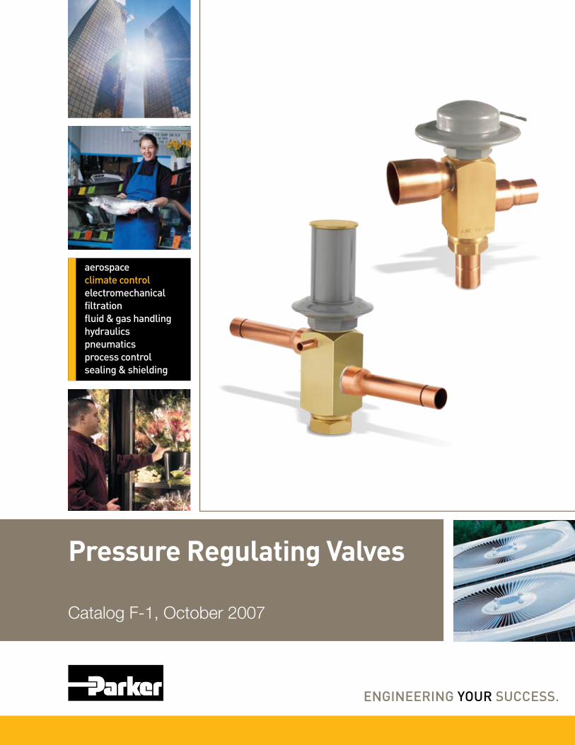
aerospaceclimate controlelectromechanicalfiltrationfluid & gas handlinghydraulicspneumaticsprocess controlsealing & shielding
Pressure Regulating Valves
Catalog F-1, October 2007

Page 2 / Catalog F-1, Pressure Regulating Valves
© Copyright 2007, Parker Hannifin Corporation, Climate and Industrial Controls Group, Cleveland, OH
Head Pressure Control Valves Operation . . . . . . . . . . . . . . . . . . . . . . . . . . . . . . . . . . . . . . . . . . . . . . . . . . . . . . . . . . . . . . . . 3
Application . . . . . . . . . . . . . . . . . . . . . . . . . . . . . . . . . . . . . . . . . . . . . . . . . . . . . . . . . . . . . . . 3
Selection Procedure . . . . . . . . . . . . . . . . . . . . . . . . . . . . . . . . . . . . . . . . . . . . . . . . . . . . . . 4
Specifications . . . . . . . . . . . . . . . . . . . . . . . . . . . . . . . . . . . . . . . . . . . . . . . . . . . . . . . . . . . . . 6
Discharge Bypass Valves
System Capacity Control . . . . . . . . . . . . . . . . . . . . . . . . . . . . . . . . . . . . . . . . . . . . . . . . . 8
Application . . . . . . . . . . . . . . . . . . . . . . . . . . . . . . . . . . . . . . . . . . . . . . . . . . . . . . . . . . . . . . . 8
Operation . . . . . . . . . . . . . . . . . . . . . . . . . . . . . . . . . . . . . . . . . . . . . . . . . . . . . . . . . . . . . . . . 10
Direct Acting Valves – ADRS, ADRP, ADRH . . . . . . . . . . . . . . . . . . . . . . . . . . . . . . . . . . . . . . . . . . . . . . 10
Adjustment Ranges/Pressure Settings . . . . . . . . . . . . . . . . . . . . . . . . . . . . . . . . . 10
Adjustable Spring Heads on Direct Acting Valves . . . . . . . . . . . . . . . . . . . . . . . . . . . . . . . . . . . . . . . . . . . . . . . 10
Specifications . . . . . . . . . . . . . . . . . . . . . . . . . . . . . . . . . . . . . . . . . . . . . . . . . . . . . . . . . . . . 10
Replacement Elements . . . . . . . . . . . . . . . . . . . . . . . . . . . . . . . . . . . . . . . . . . . . . . . . . . . . . . . . . . . . . . . . 12
Materials and Construction Details . . . . . . . . . . . . . . . . . . . . . . . . . . . . . . . . . . . . . . . . . . . . . . . . . . . . . 12
Dimensions . . . . . . . . . . . . . . . . . . . . . . . . . . . . . . . . . . . . . . . . . . . . . . . . . . . . . . . . . . . . . . . . . . . . . . . . . . 13
Selection Procedure . . . . . . . . . . . . . . . . . . . . . . . . . . . . . . . . . . . . . . . . . . . . . . . . . . . . . 11
Direct Acting Discharge Bypass Valve Capacities . . . . . . . . . . . . . . . . . . . . . . . . . . . . . . . . . . . . . . . . 14
Valve Designation/Ordering Instructions . . . . . . . . . . . . . . . . . . . . . . . . . . . . . . . . . . . . . . . . . . . . . . . . . 15

Catalog F-1, Pressure Regulating Valves / Page 3
DesignThe design of air conditioning systems utilizing air cooled condensing units involves two main problems that must be solved if the system is to operate reli-ably and economically . . . high ambient and low ambient operation. If the con-densing unit is properly sized, it will operate satisfactorily during extremely high ambient temperatures. However, since most units will be required to operate at ambient temperatures below their design dry bulb temperature dur-ing most of the year, the solution to low ambient operation is more complex.
Without good head pressure control during low ambient operation, the sys-tem can experience both running cycle and off-cycle problems. Two running cycle problems are of prime concern:
1. Since the pressure differential across the thermostatic expansion valve port affects the rate of refrigerant flow, low head pressure generally causes insufficient refrigerant to be fed to the evaporator .
2. Any system using hot gas for compres-sor capacity control must have a nor-mal head pressure to operate properly . Failure to have sufficient head pressure will result in low suction pressure and/or iced evaporator coils .
The primary off-cycle problem is refrigerant migration to the outdoor condenser and/or the receiver. The typical method of maintaining normal head pressure in an Air Conditioning
system during periods of low ambient temperature is to restrict liquid flow from the condenser to the receiver, and at the same time divert hot gas to the inlet of the receiver. This backs liquid refrigerant up into the condenser reduc-ing its capacity which in turn increases the condensing pressure. At the same time the hot gas raises liquid pressure in the receiver, allowing the system to operate normally.
OperationLAC-4 – The valve designation LAC stands for Low Ambient Control. The LAC-4 is a three way modulating valve that responds to discharge pressure. As shown in Figure 1, the discharge pressure bleeds around the pushrod to the underside of the diaphragm. The discharge pressure opposes the dome pressure. When the outdoor ambient falls, the condensing pressure falls. This causes the discharge pressure to fall as well. When the discharge pres-sure falls below the dome pressure, the valve modulates open to the discharge port which allows discharge gas to bypass the condenser. Mixing the dis-charge gas with the liquid creates a high pressure at the condenser outlet, reducing the flow and causing liquid to back up in the condenser. Flooding the condenser reduces the area avail-able for condensing. This reduction in effective condenser surface area results in a rise in condensing pressure. During summer conditions, the discharge pres-sure is high thus closing the discharge
port. Hence, there is full liquid flow from the condenser to the receiver.
LAC-5, LAC-10 – The LAC-5 and LAC-10 are also three-way modulat-ing valves but they respond to receiver pressure. As shown in Figure 2, the receiver pressure acts under the dia-phragm. As the receiver pressure drops below the valve setting, the seat moves away from the discharge port allow-ing discharge gas to bypass the con-denser. This discharge gas warms the liquid in the receiver and raises the pressure to the valve setting. At the same time discharge gas is bypassing the condenser, liquid flow from the condenser is restricted, which allows liquid to back up in the condenser. Flooding the condenser reduces the area available for condensing thus rais-ing the condensing pressure. During summer conditions, the seat closes the discharge port due to high pressure in the receiver. Therefore, there is full liquid flow from the condenser to the receiver.
ApplicationLAC Pressure Settings – The LAC valves are available with three stan-dard settings which should handle the majority of applications: 100 psig (6.9 bar) for R-134a; 295 psig (20.3 bar)for R-410A; and 180 psig (12.4 bar) for R-22, R-407C and R-502; Generally, standard settings may be used for these refrigerants but special settings may be preferred for some applications.
Refrigerant Migration – During an off cycle there is a potential for refrigerant to migrate from the warm receiver to the cold condenser. An aux-iliary check valve should be used in the liquid line between the LAC and the receiver to prevent this from occurring. See Figure 3.
While valve capacity ratings and basic selection procedures are given later, two other factors affect the proper selection of head pressure control valves . . . paralleling valves for larger systems and pressure settings. These are discussed separately below along with the other application factors that affect the operation of a system.
Head Pressure Control Valves
Discharge
Receiver
Condenser
Figure 1LAC-4
Discharge
Receiver
Condenser
Figure 2LAC-5LAC-10

Page 4 / Catalog F-1, Pressure Regulating Valves
Head Pressure Control ValvesParalleling Valves – Parker Head Pressure Control Valves may be applied in parallel to provide higher refrigerant flow rates for large systems with load requirements greater than any single valve’s capacity. Since it is not harm-ful to oversize any of these valves, it is better to select them equal to or larger than the system capacity to minimize pressure drop.
Head Pressure Control for Reclaim Systems – When employing heat reclaim on an air conditioning system, the addition of head pressure controls is important not only to maintain liq-uid pressure at the expansion valve inlet, but also to assure the availability of quality hot gas at the reclaim heat exchanger.
Pressure Settings – The pressure settings of these valves determine to a great extent how well the system will operate once they are installed. The proper setting is a function of the specific system on which the valves are applied. Generally, the setting should be equivalent to a condensing temperature of approximately 90°F to 100°F (32 to 38°C) or a receiver pressure equivalent to a temperature of approximately 80°F to 90°F (27 to 32°C). This means that when the ambient temperature falls below approximately 70°F (21°C), the head pressure control valve will start to throttle. Normally, it is not necessary or economical to operate with a higher setting than this. On systems with hot gas bypass for capacity control, or heat reclamation it is important that proper
head pressure control be utilized to ensure sufficient heat to operate. One factor to keep in mind is that the valve setting doesn’t make any difference if the system is short of refrigerant.
Piping Suggestions – Figure 3 is a piping schematic only to illustrate the general location of the head pressure control valves in the system. Parker recommends that recognized piping ref-erences be consulted for assistance in piping procedures. Parker is not respon-sible for system design, any damage arising from faulty system design, or for misapplication of its products. If these valves are applied in any manner other than as described in this bulletin, the Parker warranty is void.
Selection Procedures
The actual selection of Parker Head Pressure Control Valves involves four basic items:
1. System capacity in tons
2. Refrigerant
3. Minimum ambient design temperature
4. Allowable pressure drop across the valve
When selecting these valves it is neces-sary to consider the valve’s capacity when it is controlling at the minimum ambient design temperature. The mini-mum ambient design temperature is a
factor because the bypassed discharge gas must heat the subcooled liquid leaving the condenser to maintain the receiver pressure. This subcooled liq-uid will approach the ambient tem-perature. It is the flow of the discharge gas and liquid mixture flowing through the valve at the minimum design ambi-ent conditions that will determine the valve’s capacity. Once the valve’s capacity and pressure drop have been determined at minimum design ambi-ent conditions, the capacity of the valve during high ambient conditions should be checked to determine the pressure drop of the valve with full liquid flow.
Example – Select a LAC valve for a 10 ton (35kW), R-22 unit with a minimum design ambient temperature of -20°F (-28°C). The LAC-10 has a capacity of 10.2 tons (36.3kW) at a 2 psi (0.14 bar) drop across the valve according to the Low Ambient Capacity Table on page 5. The LAC-10 also has a capacity of 11.7 tons (41.8kW) at a 1 psi (0.07 bar) drop across the valve according to the High Ambient Capacity Table on page 6. The LAC-10 is the correct selection.
SolenoidValve
Catch-All
Compressor
See-All
TEV
External Equalizer
Check Valve
LAC
Receiver
Evaporator
Distributor
Condenser
Figure 3
Catalog F-1, Pressure Regulating Valves / Page 5
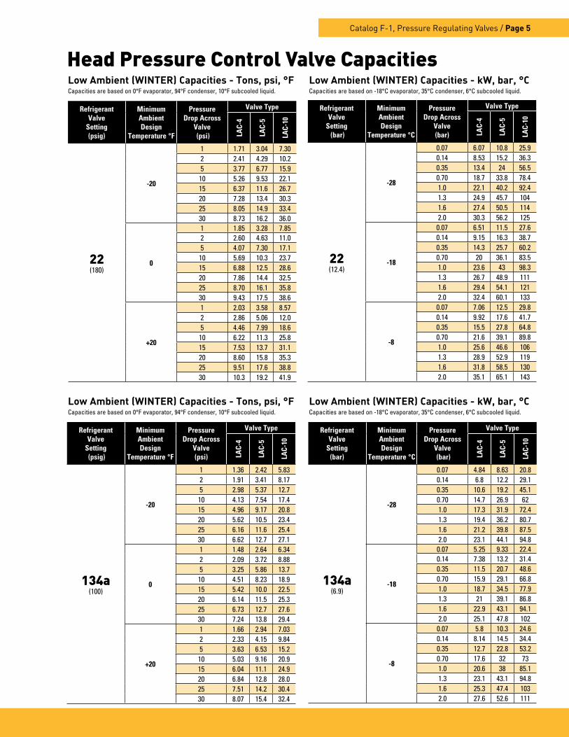
Head Pressure Control Valve Capacities
RefrigerantValve
Setting(psig)
MinimumAmbientDesign
Temperature °F
PressureDrop Across
Valve (psi)
Valve Type
LAC-
4
LAC-
5
LAC-
10
22(180)
-20
1 1 .71 3 .04 7 .302 2 .41 4 .29 10 .25 3 .77 6 .77 15 .9
10 5 .26 9 .53 22 .115 6 .37 11 .6 26 .720 7 .28 13 .4 30 .325 8 .05 14 .9 33 .430 8 .73 16 .2 36 .0
0
1 1 .85 3 .28 7 .852 2 .60 4 .63 11 .05 4 .07 7 .30 17 .1
10 5 .69 10 .3 23 .715 6 .88 12 .5 28 .620 7 .86 14 .4 32 .525 8 .70 16 .1 35 .830 9 .43 17 .5 38 .6
+20
1 2 .03 3 .58 8 .572 2 .86 5 .06 12 .05 4 .46 7 .99 18 .6
10 6 .22 11 .3 25 .815 7 .53 13 .7 31 .120 8 .60 15 .8 35 .325 9 .51 17 .6 38 .830 10 .3 19 .2 41 .9
RefrigerantValve
Setting (bar)
MinimumAmbientDesign
Temperature °C
PressureDrop Across
Valve(bar)
Valve Type
LAC-
4
LAC-
5
LAC-
10
22(12 .4)
-28
0 .07 6 .07 10 .8 25 .90 .14 8 .53 15 .2 36 .30 .35 13 .4 24 56 .50 .70 18 .7 33 .8 78 .41 .0 22 .1 40 .2 92 .41 .3 24 .9 45 .7 1041 .6 27 .4 50 .5 1142 .0 30 .3 56 .2 125
-18
0 .07 6 .51 11 .5 27 .60 .14 9 .15 16 .3 38 .70 .35 14 .3 25 .7 60 .20 .70 20 36 .1 83 .51 .0 23 .6 43 98 .31 .3 26 .7 48 .9 1111 .6 29 .4 54 .1 1212 .0 32 .4 60 .1 133
-8
0 .07 7 .06 12 .5 29 .80 .14 9 .92 17 .6 41 .70 .35 15 .5 27 .8 64 .80 .70 21 .6 39 .1 89 .81 .0 25 .6 46 .6 1061 .3 28 .9 52 .9 1191 .6 31 .8 58 .5 1302 .0 35 .1 65 .1 143
Low Ambient (WINTER) Capacities - Tons, psi, °FCapacities are based on 0°F evaporator, 94°F condenser, 10°F subcooled liquid .
RefrigerantValve
Setting(bar)
MinimumAmbientDesign
Temperature °C
PressureDrop Across
Valve (bar)
Valve Type
LAC-
4
LAC-
5
LAC-
10
134a(6 .9)
-28
0 .07 4 .84 8 .63 20 .80 .14 6 .8 12 .2 29 .10 .35 10 .6 19 .2 45 .10 .70 14 .7 26 .9 621 .0 17 .3 31 .9 72 .41 .3 19 .4 36 .2 80 .71 .6 21 .2 39 .8 87 .52 .0 23 .1 44 .1 94 .8
-18
0 .07 5 .25 9 .33 22 .40 .14 7 .38 13 .2 31 .40 .35 11 .5 20 .7 48 .60 .70 15 .9 29 .1 66 .81 .0 18 .7 34 .5 77 .91 .3 21 39 .1 86 .81 .6 22 .9 43 .1 94 .12 .0 25 .1 47 .8 102
-8
0 .07 5 .8 10 .3 24 .60 .14 8 .14 14 .5 34 .40 .35 12 .7 22 .8 53 .20 .70 17 .6 32 731 .0 20 .6 38 85 .11 .3 23 .1 43 .1 94 .81 .6 25 .3 47 .4 1032 .0 27 .6 52 .6 111
RefrigerantValve
Setting (psig)
MinimumAmbientDesign
Temperature °F
PressureDrop Across
Valve(psi)
Valve Type
LAC-
4
LAC-
5
LAC-
10
134a(100)
-20
1 1 .36 2 .42 5 .832 1 .91 3 .41 8 .175 2 .98 5 .37 12 .7
10 4 .13 7 .54 17 .415 4 .96 9 .17 20 .820 5 .62 10 .5 23 .425 6 .16 11 .6 25 .430 6 .62 12 .7 27 .1
0
1 1 .48 2 .64 6 .342 2 .09 3 .72 8 .885 3 .25 5 .86 13 .7
10 4 .51 8 .23 18 .915 5 .42 10 .0 22 .520 6 .14 11 .5 25 .325 6 .73 12 .7 27 .630 7 .24 13 .8 29 .4
+20
1 1 .66 2 .94 7 .032 2 .33 4 .15 9 .845 3 .63 6 .53 15 .2
10 5 .03 9 .16 20 .915 6 .04 11 .1 24 .920 6 .84 12 .8 28 .025 7 .51 14 .2 30 .430 8 .07 15 .4 32 .4
Low Ambient (WINTER) Capacities - kW, bar, °C Capacities are based on -18°C evaporator, 35°C condenser, 6°C subcooled liquid .
Low Ambient (WINTER) Capacities - Tons, psi, °FCapacities are based on 0°F evaporator, 94°F condenser, 10°F subcooled liquid .
Low Ambient (WINTER) Capacities - kW, bar, °C Capacities are based on -18°C evaporator, 35°C condenser, 6°C subcooled liquid .

Page 6 / Catalog F-1, Pressure Regulating Valves
Refrigerant
PressureDrop Across
Valve (psi)
Valve Type
LAC-
4
LAC-
5
LAC-
10
22
1 2 .57 5 .50 11 .72 3 .59 7 .78 16 .33 4 .37 9 .53 19 .74 5 .02 11 .0 22 .65 5 .60 12 .3 25 .16 6 .11 13 .5 27 .38 7 .02 15 .6 31 .3
10 7 .82 17 .4 34 .8
134a
1 2 .30 4 .92 10 .52 3 .22 6 .96 14 .53 3 .91 8 .53 17 .64 4 .49 9 .85 20 .25 5 .01 11 .0 22 .46 5 .47 12 .1 24 .58 6 .28 13 .9 28 .0
10 7 .00 15 .6 31 .2
410A
1 2 .44 5 .22 8 .232 3 .42 7 .38 11 .43 4 .15 9 .04 13 .94 4 .77 10 .4 15 .95 5 .32 11 .7 17 .66 5 .81 12 .8 19 .28 6 .67 14 .8 22 .0
10 7 .43 16 .5 24 .5
High Ambient (SUMMER) Capacities - Tons, psi, °FCapacities are based on 0°F evaporator, 110°F condenser, 10°F subcooled liquid .
Refrigerant
PressureDrop Across
Valve (bar)
Valve Type
LAC-
4
LAC-
5
LAC-
10
22
0 .07 9 .18 19 .6 41 .80 .14 12 .8 27 .8 580 .35 15 .6 34 70 .30 .70 17 .9 39 .3 80 .61 .0 20 44 89 .51 .3 21 .8 48 .2 97 .61 .6 25 .1 55 .6 1122 .0 27 .9 62 .2 124
134a
0 .07 8 .22 17 .6 37 .40 .14 11 .5 24 .9 520 .35 14 30 .5 630 .70 16 .1 35 .2 72 .21 .0 17 .9 39 .4 80 .21 .3 19 .5 43 .2 87 .41 .6 22 .5 49 .8 1002 .0 25 55 .7 111
410A
0 .07 8 .75 18 .7 29 .50 .14 12 .2 26 .4 40 .90 .35 14 .9 32 .4 49 .60 .70 17 .1 37 .4 56 .81 .0 19 41 .8 63 .21 .3 20 .8 45 .8 68 .91 .6 23 .9 52 .9 78 .92 .0 26 .6 59 .1 87 .7
High Ambient (SUMMER) Capacities - kW, bar, °CCapacities are based on -18°C evaporator, 43°C condenser, 6°C subcooled liquid .
Head Pressure Control Valve Capacities
RefrigerantValve
Setting(psig)
MinimumAmbientDesign
Temperature °F
PressureDrop Across
Valve (psi)
Valve Type
LAC-
4
LAC-
5
LAC-
10
410A(295)
-20
1 1 .74 3 .09 5 .832 2 .46 4 .37 8 .185 3 .85 6 .90 12 .8
10 5 .40 9 .74 17 .815 6 .56 11 .9 21 .520 7 .52 13 .7 24 .525 8 .35 15 .3 27 .030 9 .09 16 .7 29 .2
0
1 1 .88 3 .33 6 .272 2 .65 4 .71 8 .795 4 .16 7 .44 13 .7
10 5 .82 10 .5 19 .015 7 .07 12 .8 23 .020 8 .11 14 .8 26 .225 9 .00 16 .5 28 .930 9 .79 18 .0 31 .3
+20
1 2 .06 3 .63 6 .822 2 .90 5 .14 9 .565 4 .54 8 .11 14 .9
10 6 .35 11 .4 20 .715 7 .72 14 .0 24 .920 8 .84 16 .1 28 .425 9 .81 17 .9 31 .330 10 .7 19 .6 33 .9
RefrigerantValve
Setting (bar)
MinimumAmbientDesign
Temperature °C
PressureDrop Across
Valve(bar)
Valve Type
LAC-
4
LAC-
5
LAC-
10
410A(20 .3)
-28
0 .07 6 .17 10 .9 20 .60 .14 8 .69 15 .5 28 .90 .35 13 .6 24 .4 45 .10 .70 19 .1 34 .5 62 .81 .0 22 .7 41 .7 74 .21 .3 25 .7 46 .7 83 .71 .6 28 .3 51 .7 91 .92 .0 31 .4 57 .7 101
-18
0 .07 6 .61 11 .7 22 .00 .14 9 .31 16 .5 30 .90 .35 14 .6 26 .1 48 .10 .70 20 .4 36 .8 66 .91 .0 24 .3 43 .9 78 .91 .3 27 .5 50 .0 89 .01 .6 30 .3 55 .3 97 .72 .0 33 .6 61 .6 108
-8
0 .07 7 .16 12 .6 23 .70 .14 10 .1 17 .8 33 .20 .35 15 .8 28 .2 51 .70 .70 22 .1 39 .7 71 .81 .0 26 .2 47 .4 84 .71 .3 29 .7 53 .9 95 .51 .6 32 .7 59 .7 1052 .0 36 .3 66 .5 115
Low Ambient (WINTER) Capacities - Tons, psi, °FCapacities are based on 0°F evaporator, 94°F condenser, 10°F subcooled liquid .
Low Ambient (WINTER) Capacities - kW, bar, °C Capacities are based on -18°C evaporator, 35°C condenser, 6°C subcooled liquid .

Catalog F-1, Pressure Regulating Valves / Page 7
Valve Type
Standard FactorySetting (psig)
Connections ODF Solder
(Inches)
Dimensions(Inches)
Weight(lbs.) Replacement Parts
Inlet(s) Outlet A B C D E F H I Net Ship
LAC-4
100, 180, or
295
1/4 1/41 .78 1 .87 3 .02 2 .38 4 .73
– – –
0 .77 0 .85
Repl
acem
ent E
lem
ents
NotAvailable 3/8 3/8 0 .80 0 .88
1/2 1/2 0 .82 0 .90
LAC-5
1/2 1/2 1 .65 1 .60 3 .77 2 .99
D3L
6 .10
R3L
5 .59 2 .50 2 .65Non-Adjustable Dome Element: D3L (specfiy setting) or Non-Adjustable Remote Bulb Element: R3L (specify setting)
5/8 5/8 1 .74 1 .69 3 .86 3 .08 6 .19 5 .68 2 .55 2 .70 7/8 7/8 2 .23 2 .18 4 .35 3 .57 6 .68 6 .17 2 .60 2 .75 1-1/8 1-1/8 2 .38 2 .33 4 .50 3 .72 6 .83 6 .32 2 .75 2 .90
LAC-10
1 1-3/8 2 7/8 7/8
2 .822 .67 4 .39 3 .43 6 .91 6 .40 3 .20 3 .42
1 1-3/8 2 1-1/8 1-1/8 2 .56 4 .83 3 .87 7 .35 6 .84 3 .28 3 .50
Valve Type Adjustable Port Size
(Inches)Element Type &
MaterialConnections
Body Material Seating Material Type of JointsType Material
LAC-4No
1/2Domed Steel Solder Copper Brass Metal to Metal Knife Edge
(Metal to Metal)LAC-5 5/8LAC-10 3/4
Specifications - Inches
Materials and Construction Details
Underwriter’s Laboratory InformationThe LAC valves are all U .L . Recognized components . The MRP for the LAC-4 is 500 psig (34 .5 bar), while the LAC-5, and LAC-10 have a MRP of 450 psig (31 bar) . All valves are in U .L . file SA-5460 .
1 Discharge Connection, 2 Condenser Connection
Valve Type
Standard FactorySetting
(bar)
Connections ODF Solder
(Inches)
Dimensions(mm)
Weight(Kg) Replacement Parts
Inlet(s) Outlet A B C D E F H I Net Ship
LAC-4
6 .912 .4or
20 .3
1/4 1/445 48 77 60 120
– – –
.35 .39
Repl
acem
ent E
lem
ents
NotAvailable3/8 3/8 .36 .40
1/2 1/2 .37 .41
LAC-5
1/2 1/2 42 41 93 76
D3L
155
R3L
142 1 .13 1 .20Non-Adjustable Dome Element: D3L (specfiy setting) or Non-Adjustable Remote Bulb Element: R3L (specify setting)
5/8 5/8 44 43 98 78 157 144 1 .16 1 .227/8 7/8 57 55 110 91 170 157 1 .18 1 .25
1-1/8 1-1/8 61 59 114 95 173 161 1 .25 1 .32
LAC-10
1 1-3/8 2 7/8 7/8
7268 112 87 176 163 1 .45 1 .55
1 1-3/8 2 1-1/8 1-1/8 65 123 98 187 173 1 .49 1 .59
Specifications - Metric
1 Discharge Connection, 2 Condenser Connection

Page 8 / Catalog F-1, Pressure Regulating Valves
System Capacity ControlOn many air conditioning systems it is desirable to limit the minimum evapo-rating pressure during periods of low load either to prevent coil icing or to avoid operating the compressor at a lower suction pressure than it was designed to operate. Various methods have been used to achieve this result — integral cylinder unloading, variable speed control, or multiple smaller sys-tems. Compressor cylinder unloading is used extensively on larger systems but is too costly on small equipment, usually 10 hp and below. Cycling the compressor with a low pressure cutout control is a method used in limited applications, but has the following three concerns.
1. On-off control on air conditioning systems is uncomfortable and does a poor job of humidity and mold control .
2. Compressor cycling reduces equipment life .
3. In most cases, compressor cycling is not economical because of peak load demand charges .
One method that offers a practical and economical solution to the problem, is to bypass a portion of the hot discharge gas directly into the low side. This is done by a modulating control valve — commonly called a Discharge Bypass Valve (DBV). This valve, which opens on a decrease in suction pressure, can be set to auto-matically maintain a desired minimum evaporating pressure regardless of the decrease in evaporator load.
ApplicationParker Discharge Bypass Valves pro-vide an economical method of compres-sor capacity control in place of cylinder unloaders or the handling of unloading requirements below the last step of cyl-inder unloading.
On air conditioning systems, the mini-mum allowable evaporating tempera-ture that will avoid coil icing depends on evaporator design and the amount of air passing over the coil. The refrigerant temperature may be below 32°F (0°C), but coil icing will not usually occur with high air velocities since the external surface temperature of the tube will be
above 32°F (0°C). For most air condi-tioning systems the minimum evaporat-ing temperature is 20°F to 25°F (-6.7 to -3.9°C). However, when air velocities are reduced considerably, the minimum evaporating temperature should be 26°F to 28°F (-3.3 to -2.2°C).
Parker Discharge Bypass Valves can be set so they start to open at an evaporating pressure equivalent to 32°F (0°C) satura-tion temperature. Therefore, they would be at their rated capacity at 26°F (-3.3°C) evaporating temperature.
The discharge bypass valve is applied in a branch line, off the discharge line, as close to the compressor as possible. The bypassed vapor can enter the low side at one of the following locations:
1. Evaporator inlet with distributor .
2. Evaporator inlet without distributor .
Each is illustrated and discussed below. While Figure 4 shows a specific type of discharge bypass valve, all types can be used in place of the one shown.
Discharge Bypass Valves for System Capacity Control
LAC – 4 – 100/180/295 HP – 3/8 x 3/8 x 3/8 ODF
Valve TypeLow
Ambient Control
Valve Size
Valve Setting(s) (psig)Specifiy one setting for standard dome element
DischargeConnection
(Inches)
Condenser Connection
(Inches)
ReceiverConnection
(Inches)
SolderConnections
LAC – 5 – 180/295 HP – 5/8 x 5/8 x 5/8 ODF
Valve TypeLow
Ambient Control
Valve Size
Valve Setting(psig)
DischargeConnection
(Inches)
Condenser Connection
(Inches)
ReceiverConnection
(Inches)
SolderConnections
Valve Designation/Ordering InstructionsTo eliminate shipment delays, specify complete valve designation .
LAC-4
D
BA
1 .94
C
E
Condenser
Discharge
Receiver
LAC-5 and LAC-10
DC
E
A B
3 .62
3 .62
.75
4 .00
R3LD3L
Condenser
Discharge
Receiver
Head Pressure Control Valves - Dimensions

Catalog F-1, Pressure Regulating Valves / Page 9
External Equalizer
Evaporator
External Equalizer
Hot Gas Solenoid Valve
CompressorCondenser
Rece
iver
Catch-All
Side ConnectionDistributor or ASC
TEV See-All
Solenoid Valve
DischargeBypass Valve
Figure 4
Bypass to Evaporator Inlet with DistributorThis method of application, illustrated in Figure 4, provides distinct advantag-es over the other methods, especially for unitary or field built-up units where the high and low side are close coupled.
This method is also applicable on systems with remote condensing units, especially when the evaporator is located below the condensing unit, see discussion below.
The primary advantage of this method is that the system thermostatic expan-sion valve will respond to the increased superheat of the vapor leaving the evapo-rator and will provide the liquid required for desuperheating. Also the evaporator serves as an excellent mixing cham-ber for the bypassed hot gas and the liquid-vapor mixture from the expansion valve. This ensures a dry vapor reaching the compressor. Oil return from the evapo-rator is also improved since the velocity in the evaporator is kept high by the hot gas.
Parker Distributor or ASC - Two refrigerant distribution methods are available to introduce hot gas in this manner:
1. Bypass to Parker distributor with an aux-iliary side connection .
2. Bypass to Parker ASC series Auxiliary Side Connector .
Method 1 is normally utilized on factory assembled or unitary systems where hot gas bypass is initially designed into the system. The Parker distributor allows the hot gas to enter downstream
of the distributor nozzle. Method 2 is applicable on field built-up systems or on existing systems where the stan-dard refrigerant distributor is already installed on the evaporator.
Some caution is necessary with either of these methods. If the distributor circuits are sized properly for normal cooling duty, the flow of hot gas through the cir-cuits may cause excessive pressure drop and/or noise. Therefore, it is recom-mended that the distributor circuits be selected one size larger than for straight cooling duty. See Selection Procedures Section for selection information on this method of hot gas bypass. For complete technical details on the Parker series distributor and the ASC series Auxiliary Side Connector, refer to page 15, or Catalog O-3.
Valve/Equipment Location and Piping – When the evaporator is locat-ed below the compressor on a remote system, bypass to the evaporator inlet is still the best method of hot gas bypass to ensure sufficient oil return to the compressor. In order for the bypass to achieve rated capacity at the conditions for which it was selected, the bypass valve and hot gas solenoid valve (if used) must be located at the compres-sor, rather than at the evaporator. If the evaporator is above or on the same level as the compressor, this valve location will also eliminate the possibility of hot gas condensing in the long bypass line and running back into the compressor during the off cycle.
Whenever hot gas bypass to the evapora-tor inlet is necessary for a system with two or more evaporator sections, each with its own TEV (no liquid line solenoid
valves), but handling the same load, two methods may be used to avoid operating interference between sections:
1. Use a separate discharge bypass valve for each evaporator section .
2. Use one discharge bypass valve to feed two bypass lines, each with a check valve between the bypass valve and the evapo-rator section inlet . The check valves will prevent interaction between the TEVs when the bypass valve is closed .
Externally Equalized Bypass Valves – Since the primary function of the DBV is to maintain suction pres-sure, the compressor suction pressure is the control pressure and must be exerted on the underside of the valve diaphragm. When the DBV is applied as shown in Figure 4, where there is an appreciable pressure drop between the valve outlet and the compressor suction, the externally equalized valve must be used. This is true because when the valve opens, a sudden rise in pressure occurs at the valve outlet. This creates a false control pressure, which causes the internally equalized valve to close.
Caution – Introduction of the bypassed gas between the thermostatic expansion valve and the distributor is not gener-ally recommended because of the large pressure drop caused by the hot gas flowing through the distributor nozzle, or throat, and the tube circuits, which have been sized for normal cooling flow rates. Careful evaluation and testing should precede any application where hot gas is bypassed between the TEV and the distributor.
Bypass to Evaporator Inlet without Distributor – Many refrigeration sys-tems and water chillers do not use refrig-erant distributors, but may require some method of compressor capacity control. This type of application provides the same advantages as bypassing hot gas to the evaporator inlet with a distributor. All information relating to bypassing hot gas to the evaporator inlet with a distributor, except that concerning distributors or ASCs, also applies to bypassing to the evaporator inlet without a distributor.
Paralleling Valves – If the hot gas bypass requirement on any system is greater than the capacity of the largest discharge bypass valve, these valves can be applied in parallel. The pressure settings of the paralleled valves should be the same to get the most sensitive performance, and the piping to each valve should be identical to keep the pressure drop across each valve the same.
Discharge Bypass Valves for System Capacity Control

Page 10 / Catalog F-1, Pressure Regulating Valves
Piping Suggestions – Figure 4 is a piping schematics only to illustrate the general location of the discharge bypass valves in the system. Parker recommends that recognized piping references, such as equipment manu-facturers’ literature and the ASHRAE Handbook, be consulted for assistance. Parker is not responsible for system design, any damage arising from faulty system design, or for misapplication of its products. If these valves are applied in any manner other than as described in this bulletin, the Parker warranty is void. Actual system piping must be done so as to protect the compressor at all times. This includes protection against overheating, slugging with liq-uid refrigerant, and trapping of oil in various system locations.
The inlet connection on the discharge bypass valve should be sized to match system piping requirements. If a hot gas solenoid valve is used, its con-nection size will help determine the necessary connections on the bypass valve. Matching connections is easy if all components are reviewed in light of the most efficient system operation: side connection on distributor or ASC, hot gas solenoid valve, discharge line, suction line, etc.
Inlet strainers are available for all sol-der type bypass valves. The need for an inlet strainer is a function of system cleanliness. Moisture and particles too small for the strainer are harmful to the system and must also be removed. Therefore, it is recommended that a Parker Filter-Drier be applied in the liquid line and suction line (if required). See Catalog A-1.
Hot Gas Solenoid Valve – The sche-matic drawing in this application sec-tion shows a solenoid valve in a hot gas bypass line. Systems that operate on a pump down cycle require a sole-noid valve in the hot gas bypass line in addition to the liquid line solenoid valve, since the bypass valve will open as the suction pressure is reduced. The two solenoid valves, hot gas and liquid line, should be wired in parallel so they are de-energized by a thermostat or any of the compressor safety devices, after which the compressor will shut down.
Even if the system is not on a pump down cycle, it is usually best to have a shut-off valve in the hot gas bypass line so the system can be pumped down for service.
A hot gas solenoid valve is also needed if the compressor does not have an inte-
gral temperature protection device. The valve serves as a safety measure against an extremely high superheat condition at the compressor suction. This condi-tion can occur if the system experi-ences a malfunction of the thermostatic expansion valve, which is serving to desuperheat the bypassed hot gas; or, if the system is short of refrigerant. The hot gas solenoid valve is wired in series with a bi-metal thermostat fastened to the discharge line close to the compres-sor. This causes the solenoid valve to close if the discharge line temperature becomes excessive.
Complete selection information is given in the Selection Procedures Section.
DBV with Other Pressure Regulating Valves – If the discharge bypass valve is required on a system with a crankcase pressure regulating valve, the pressure setting of the DBV must be lower than the CRO valve setting for each valve to function properly.
Normally, when hot gas bypass is used for capacity control during periods of low load, the outdoor ambient drops below 70°F (21.1°C). Therefore, all air cooled systems that utilize hot gas bypass for capacity control should have some type of head pressure control to maintain satisfactory performance.
For information on other Parker pres-sure regulating valves refer to pages 3-6 and/or Parker Refrigerating Specialites Flo•Con Catalog 611F.
OperationDirect Acting Valves – ADRS, ADRP, and ADRH – Parker DBVs respond to changes in downstream or suction pres-
sure. See Figure 5. When the evaporat-ing pressure is above the valve setting, the valve remains closed. As the suction pressure drops below the valve setting, the valve responds and begins to open. As with all modulating type valves, the amount of opening is proportional to the change in the variable being controlled — in this case the suction pressure. As the suction pressure continues to drop, the valve continues to open until the limit of the valve stroke is reached. However, on normal applications there is not sufficient pressure change to open these valves to the limit of their stroke. The amount of pressure change from the point at which it is desired to have the valve closed, to the point at which it is to open, varies widely with the type of refrigerant used and the evaporat-ing temperature. For this reason Parker DBVs are rated on the basis of allow-able evaporator temperature change from closed position to rated opening. A 6°F (3.33°C) change is considered normal for most applications and is the basis of our capacity ratings. Multipliers for other temperature changes are given in the Selection Procedures section.
These factors must be considered in the application and selection of all DBV’s. Therefore, the following sections com-pletely explain how the various factors are utilized in determining the proper valve to use, and the correct method of application.
Adustable Ranges Pressure SettingsAdjustable Spring Heads on Direct Acting Valves – The fully adjustable type utilizes a spring assembly which can be fixed at the desired pressure
Adjusting Spring
External Equalizer
Diaphragm
Seat
Strainer
Piston Assembly
U.S. Patent Number 3,402,566
ADRHE-6
Discharge Bypass Valves for System Capacity Control
Figure 5

Catalog F-1, Pressure Regulating Valves / Page 11
setting (opening pressure). This setting will not be affected by other factors such as ambient or hot gas tempera-tures. The ADRS(E)-2, ADRP(E)-3 and ADRH(E)-6 are available with a fully adjustable range of 0/80 psig. The stan-dard factory settings for the fully adjust-able, 0/30, range is 20 psi.
The 0/80 range is generally required for air conditioning systems. The capacity table shows the evaporating tempera-tures at which the valves can be applied.
SpecificationsParker Discharge Bypass Valves utilize many of the proven construction fea-tures of our line of thermostatic expan-sion valves. The valves are constructed of the finest materials — those best suited for the specific purpose intended for each valve component. This ensures long life and dependable service.
Since there are numerous models avail-able, valve designations have been made distinctly different to aid in speci-fying each type properly. Refer to the Ordering Instructions on Page 13 for an explanation of the valve designations.
Element Designations – The table on page 12 lists the element and spring range for each valve type. When order-ing any element, the adjustment range and the valve type must be specified.
The fully adjustable spring ele-ment A3-0/80 and is interchangeable between the ADRPE and ADRHE valve models.
Selection ProceduresThe selection of a discharge bypass valve, and the necessary companion devices, is simplified if complete system information is available. This will result in the most economical selection because the components will match the system requirements.
Besides the discharge bypass valve, a specific application may require a hot gas solenoid valve and an auxiliary side connection distributor or ASC adaptor. Once the type of application (review Application Section) is determined, the necessary valves can be selected from the information discussed in this sec-tion.
Discharge Bypass Valves – The selec-tion of a Parker Discharge Bypass Valve involves five basic items:
1. Refrigerant - valve capacities vary con-siderably for different refrigerants .
2. Minimum allowable evaporating tem-perature at the reduced load condition - depending on the system, this value must be set to prevent coil icing and/or compressor short cycling . For example, this may be 32°F to 34°F (0°C to 1 .1°C) for a water chiller; 26°F to 28°F (-3 .3°C to -2 .2°C) for a normal air conditioning system; and, the freezing temperature of the specific product for a refrigeration system .
3. Compressor capacity (tons) at minimum allowable evaporating temperature - consult compressor capacity ratings for this value .
4. Minimum evaporator load (tons) at which the system is to be operated - most sys-tems are not required to operate down to zero load but this value will depend on the type of system . For example, most air con-ditioning systems only need to operate down to 15-25% of full load . However, air conditioning systems for data processing and “white” rooms, and most refrigera-tion systems may be required to bypass to zero load conditions .
5. Condensing temperature when minimum load exists - since the capacity ratings of the bypass valves are a function of con-densing temperature, it is vital that proper head pressure is maintained, especially during low load operation . As the capac-ity table indicates, a condensing tempera-ture of 80°F (26 .7°C) is considered the minimum allowable for satisfactory system operation . See pages 3-8 for information on Parker’s Head Pressure Valves .
The discharge bypass valve must be selected to handle the difference between items 3 and 4 above. If the minimum evaporator load (item 4) is zero, the hot gas bypass requirement is simply the compressor capacity at the minimum allowable evaporating temperature (item 3). The following discussion on Capacity Ratings and the Example show how these factors affect a selection on a typical air conditioning system.
Capacity Ratings – As the Discharge Bypass Valve Capacity Table indicates, valve ratings are dependent on the evapo-rating and condensing temperature at the reduced load condition and the refrig-erant used. Therefore, once this informa-tion and the hot gas bypass requirement in tons is determined, a discharge bypass valve can be selected.
As the capacity table heading indicates, these are valve capacities, not the system capacity on which the valve is applied. The ratings are the sum of the hot gas bypassed and the liquid refriger-
ant for desuperheating. The capacities are based on an evaporator temperature change of 6°F (3.33°C) from a closed position to the rated opening. This is a nominal rating value based on years of application experience. Since a discharge bypass valve is actually a pressure regulating valve, it should be pointed out that the capacity ratings based on a 6°F (3.33°C) evaporator temperature change take into account that a 6°F (3.33°C) change @ 40°F (4.4°C) on Refrigerant 22 is a 9.1 psi (0.63 bar) change, The 6°F (3.33°C) nominal change is used so all the various pressure changes do not need to be shown in the table. If additional capacity is required and a greater evaporator temperature change can be tolerated, these valves are capable of opening further. Capacity multipli-ers for this purpose. For example, an ADRHE-6-0/80 rated for 9.58 tons at a 26°F evaporating temperature will start to open at 32°F (26° + 6°); and, when the evaporating temperature has dropped to 26°F (-3°C), the valve will be open far enough to bypass 9.9 tons of hot gas. If a temperature change of 8°F can be toler-ated, the valve would start opening at 34°F (26° + 8°) and be open far enough to bypass 9.9 times 1.15 or 11.39 tons of hot gas.
Occasionally, a bypass valve is selected for an evaporator temperature change of less than 6°F (3.33°C). Multipliers for those situations are also given in the table on page 12.
Example – Select a discharge bypass valve for a 20 ton (70kW) Refrigerant 22 air conditioning system with 67% cylinder unloading (4 of 6 cylinders unloaded). Normal operating conditions are 45°F (7.2°C) evaporating tempera-ture and 120°F (48.9°C) condensing temperature with a minimum con-densing temperature of 80°F (26.7°C)due to head pressure control.
When the evaporator load drops below the last step of cylinder unloading, it is necessary to keep the system on-the-line to maintain proper space temperatures, and avoid frosting of the coil. From the compressor manufacturer’s capacity table, the compressor capacity in tons at the minimum allowable evaporating temperature is approximately 7 tons (25kW). If the system had to be on-the-line down to zero load, the bypass valve would have to bypass 7 tons (25kW) of hot gas. With the necessary system factors — R-22, 26°F (-3°C) evaporat-ing temperature at the reduced load condition, and 80°F (26.7°C) condens-ing temperature — the capacity table is
Discharge Bypass Valves for System Capacity Control

Page 12 / Catalog F-1, Pressure Regulating Valves
Direct Acting Valves - Materials and Construction DetailsValve Type Port Size
(Inches)Element Type and Material
ConnectionsBody Material Seating
Material Type of JointsType Material
ADRS(E)-2 1/4Diaphragm -
Stainless Steel
Solder CopperBrass
Metal-to-Metal Knife Edge Metal-to-MetalADRS(E)-3 3/8 Solder Copper
ADRS(E)-6 3/4 Solder Copper Synthetic-to-Metal
The DRS(E), DRP(E) and DRHE valves are all recognized components under Underwriter’s Laboratories Guide Number SFJQ2, File Number SA5460. The maximum rated pressure for all models is 500 psig (3448 kPa).
Replacement ElementsReplacement Element Type Fits Valve Type Standard Adjustment
Range (psig) Standard Settings
Adjustable Spring Type
A-8-1 ADRS-2 0/80 60A-3-1 ADRP-3
0/30 20A-3-1 ADRH-6
1 Specify Range of Adjustment
checked for a valve which can handle the 7 tons (25kW) bypass capacity:
The ADRHE-6-0/80 AR has a capacity of 7.69 tons (27kW) at these condi-tions. Therefore, if the system must operate to zero load, this would be the proper selection.
However, if the minimum evaporator load is 4 tons (14.1kW) (20% of total system capacity), an ADRPE-3-0/80 would be the proper selection (valve capacity of 4.86 tons (17.1kW)). The only additional information necessary is the valve connections. While various connections are available, the proper valve connections must be selected to match the system’s piping requirements. Hot Gas Solenoid Valves – The selec-tion of a Parker Hot Gas Solenoid Valve involves some of the same basic items already determined for the selection of the discharge bypass valve plus one additional factor:
1. Refrigerant.
2. Minimum allowable evaporating tem-perature at the reduced load condition.
3. Hot gas bypass requirement in tons - this is not the bypass valve capacity .
4. Allowable pressure drop across valve port - since excessive pressure drop across the solenoid valve reduces the capacity of the DBV, the recommended pressure drop for a Refrigerant 134a system is approximately 5 psi (0 .35 bar) and for a Refrigerant 22 system approxi-mately 10 psi (0 .70 bar) .
Capacity Ratings – Once the data listed above is determined, the appro-priate solenoid valve can be easily selected from the capacity table.
Example – Based on the data for the earlier DBV selection: Refrigerant 22, 26°F (-3°C) minimum allowable evap-
orating temperature at the reduced load condition, and either 7 tons (25kW) or 4 tons (14.1kW) as the hot gas bypass requirement, the best solenoid valve selection for each case would be:
For 7 tons: R30E15, 7/8” or 1-1/8” ODF connec-tions, and the necessary voltage and cycles.
For 4 tons:R30E12, 5/8” ODF connections, and the necessary voltage and cycles.
The R30E15 and R30E12 would have a pressure drop of greater than 5 psi (0.35 bar). Both selections depend on whether adequate condensing pressure is maintained year round with some form of head pressure control. See HPC Valve section, pages 3-8.
Discharge Bypass Valves for System Capacity Control
Capacity Multipliers - °Ffor Evaporator Temperature Changes Other Than 6°F Nominal Change
Evaporator Temperature Change – °F Refrigerant
EvaporatorTemperature – °F40 26 20
2134a, 401A 0 .65 0 .65 0 .65
22, 402A, 404A, 407C, 507 0 .72 0 .70 0 .70410A .045 0 .40 0 .38
4134a, 401A 0 .80 0 .80 0 .80
22, 402A, 404A, 407C, 507 0 .87 0 .85 0 .85410A 0 .82 0 .78 0 .76
8134a, 401A 1 .11 1 .11 1 .11
22, 402A, 404A, 407C, 507 1 .17 1 .15 1 .11410A 1 .08 1 .11 1 .13
10134a, 401A 1 .22 1 .20 1 .19
22, 402A, 404A, 407C, 507 1 .34 1 .27 1 .25410A 1 .11 1 .17 1 .20
Capacity Multipliers - °Cfor Evaporator Temperature Changes Other Than 3.33°C Nominal Change
Evaporator Temperature Change – °C Refrigerant
EvaporatorTemperature – °C
4.4 -3.3 -6.3
1.1134a, 401A 0 .65 0 .65 0 .65
22, 402A, 404A, 407C, 507 0 .72 0 .70 0 .70410A .045 0 .40 0 .38
2.2134a, 401A 0 .80 0 .80 0 .80
22, 402A, 404A, 407C, 507 0 .87 0 .85 0 .85410A 0 .82 0 .78 0 .76
4.4134a, 401A 1 .11 1 .11 1 .11
22, 402A, 404A, 407C, 507 1 .17 1 .15 1 .11410A 1 .08 1 .11 1 .13
5.6134a, 401A 1 .22 1 .20 1 .19
22, 402A, 404A, 407C, 507 1 .34 1 .27 1 .25410A 1 .11 1 .17 1 .20

Catalog F-1, Pressure Regulating Valves / Page 13
Valve Type Connections(Inches)
Standard Connectionsin BOLD
Dimensions (Inches) Weight (Pounds)Inlet Strainer Part NumberInternally
EqualizedExternally
Equalized 1 A B C D E F SocketDepth Net Shipping
Adjustable Models
ADRS-2 ADRSE-23/8 ODF
6 .44 2 .50 1 .941 .44
2 .750 .31
2 .00 2 .25877-3
1/2 ODF 1 .37 0 .37 877-45/8 ODF 1 .50 0 .50 877-5
ADRP-3 ADRPE-31/2 ODF
6 .94 2 .81 2 .061 .69 1 .62
2 .750 .37
2 .75 3 .00877-4
5/8 ODF 1 .81 1 .75 0 .50 887-5
Not Available ADRHE-65/8 ODF
7 .06 2 .88 1 .88 4 .62 2 .750 .50
3 .50 4 .00877-5
7/8 ODF 0 .75 877-71-1/8 ODF 0 .91 825-9
Direct Acting Valves - Dimensions - Inches
1 Standard External Equalizer connection is 1/4” ODF.
A
B
F
D E
C
ADR
Discharge Bypass Valves for System Capacity Control
Valve Type Connections(Inches)
Standard Connectionsin BOLD
Dimensions (cm) Weight (Kg)Inlet Strainer Part NumberInternally
EqualizedExternally
Equalized 1 A B C D E F SocketDepth Net Shipping
Adjustable Models
ADRS-2 ADRSE-23/8 ODF
16 .4 6 .4 4 .93 .66
6 .90 .79
5 .1 5 .7877-3
1/2 ODF 3 .48 0 .94 877-45/8 ODF 3 .81 1 .27 877-5
ADRP-3 ADRPE-31/2 ODF
17 .6 7 .1 5 .24 .29 4 .11
6 .90 .94
7 .0 7 .6877-4
5/8 ODF 4 .60 4 .45 1 .27 887-5
Not Available ADRHE-65/8 ODF
17 .9 7 .3 4 .8 11 .7 6 .91 .27
8 .9 10 .2877-5
7/8 ODF 1 .91 877-71-1/8 ODF 2 .31 825-9
Direct Acting Valves - Dimensions - Metric
1 Standard External Equalizer connection is 1/4” ODF.
Page 14 / Catalog F-1, Pressure Regulating Valves
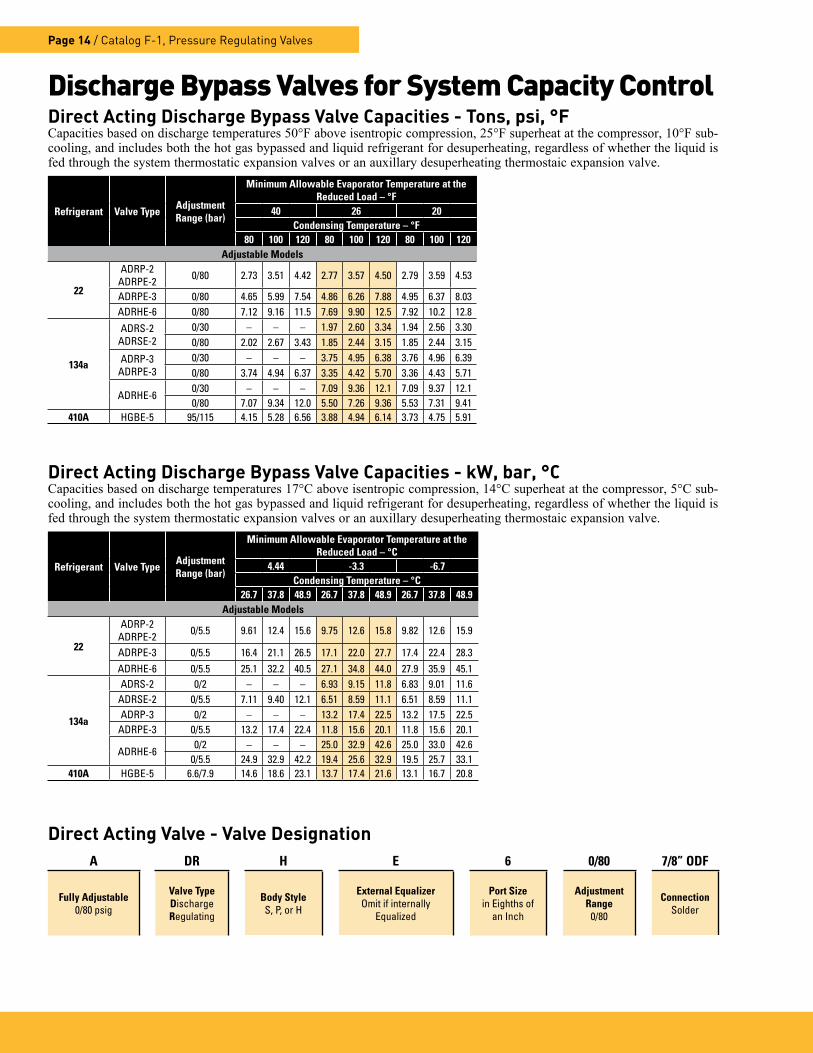
Direct Acting Discharge Bypass Valve Capacities - Tons, psi, °FCapacities based on discharge temperatures 50°F above isentropic compression, 25°F superheat at the compressor, 10°F sub-cooling, and includes both the hot gas bypassed and liquid refrigerant for desuperheating, regardless of whether the liquid is fed through the system thermostatic expansion valves or an auxillary desuperheating thermostaic expansion valve.
Refrigerant Valve Type Adjustment Range (bar)
Minimum Allowable Evaporator Temperature at the Reduced Load – °F
40 26 20Condensing Temperature – °F
80 100 120 80 100 120 80 100 120Adjustable Models
22
ADRP-2ADRPE-2 0/80 2 .73 3 .51 4 .42 2 .77 3 .57 4 .50 2 .79 3 .59 4 .53
ADRPE-3 0/80 4 .65 5 .99 7 .54 4 .86 6 .26 7 .88 4 .95 6 .37 8 .03ADRHE-6 0/80 7 .12 9 .16 11 .5 7 .69 9 .90 12 .5 7 .92 10 .2 12 .8
134a
ADRS-2ADRSE-2
0/30 – – – 1 .97 2 .60 3 .34 1 .94 2 .56 3 .300/80 2 .02 2 .67 3 .43 1 .85 2 .44 3 .15 1 .85 2 .44 3 .15
ADRP-3ADRPE-3
0/30 – – – 3 .75 4 .95 6 .38 3 .76 4 .96 6 .390/80 3 .74 4 .94 6 .37 3 .35 4 .42 5 .70 3 .36 4 .43 5 .71
ADRHE-60/30 – – – 7 .09 9 .36 12 .1 7 .09 9 .37 12 .10/80 7 .07 9 .34 12 .0 5 .50 7 .26 9 .36 5 .53 7 .31 9 .41
410A HGBE-5 95/115 4 .15 5 .28 6 .56 3 .88 4 .94 6 .14 3 .73 4 .75 5 .91
Direct Acting Valve - Valve DesignationA DR H E 6 0/80 7/8” ODF
Fully Adjustable0/80 psig
Valve TypeDischargeRegulating
Body StyleS, P, or H
External Equalizer Omit if internally
Equalized
Port Sizein Eighths of
an Inch
Adjustment Range
0/80
ConnectionSolder
Discharge Bypass Valves for System Capacity Control
Direct Acting Discharge Bypass Valve Capacities - kW, bar, °CCapacities based on discharge temperatures 17°C above isentropic compression, 14°C superheat at the compressor, 5°C sub-cooling, and includes both the hot gas bypassed and liquid refrigerant for desuperheating, regardless of whether the liquid is fed through the system thermostatic expansion valves or an auxillary desuperheating thermostaic expansion valve.
Refrigerant Valve Type Adjustment Range (bar)
Minimum Allowable Evaporator Temperature at the Reduced Load – °C
4.44 -3.3 -6.7Condensing Temperature – °C
26.7 37.8 48.9 26.7 37.8 48.9 26.7 37.8 48.9Adjustable Models
22
ADRP-2ADRPE-2 0/5 .5 9 .61 12 .4 15 .6 9 .75 12 .6 15 .8 9 .82 12 .6 15 .9
ADRPE-3 0/5 .5 16 .4 21 .1 26 .5 17 .1 22 .0 27 .7 17 .4 22 .4 28 .3ADRHE-6 0/5 .5 25 .1 32 .2 40 .5 27 .1 34 .8 44 .0 27 .9 35 .9 45 .1
134a
ADRS-2 0/2 – – – 6 .93 9 .15 11 .8 6 .83 9 .01 11 .6ADRSE-2 0/5 .5 7 .11 9 .40 12 .1 6 .51 8 .59 11 .1 6 .51 8 .59 11 .1ADRP-3 0/2 – – – 13 .2 17 .4 22 .5 13 .2 17 .5 22 .5
ADRPE-3 0/5 .5 13 .2 17 .4 22 .4 11 .8 15 .6 20 .1 11 .8 15 .6 20 .1
ADRHE-60/2 – – – 25 .0 32 .9 42 .6 25 .0 33 .0 42 .6
0/5 .5 24 .9 32 .9 42 .2 19 .4 25 .6 32 .9 19 .5 25 .7 33 .1410A HGBE-5 6 .6/7 .9 14 .6 18 .6 23 .1 13 .7 17 .4 21 .6 13 .1 16 .7 20 .8

Catalog F-1, Pressure Regulating Valves / Page 15
Auxiliary side connectors (ASCs) permit removable nozzle type refrigerant dis-tributors, without side connections, to be used for hot gas bypass, hot gas defrost, or reverse cycle applications, see Figure 6.
The ASC is installed between the TEV and distributor. First, the nozzle and retainer ring are removed from the dis-tributor and reinstalled in the ASC inlet. The ASC outlet is then connected to the distributor inlet. The inlet of the ASC is connected to the TEV outlet.
As with side connection type distribu-tors, the ASC allows hot gas or liquid refrigerant in the reverse cycle to bypass the nozzle. In addition, the two-phase re-frigerant flowing from the TEV passes through the nozzle, and a nozzle tube ex-tension, which terminates at the distribu-tor’s dispersion cone. This tube elimi-nates any interference in TEV flow from hot gas flow entering through the side
connection. The tube is supported by a perforated web allowing hot gas or liquid refrigerant in the reverse cycle to flow through with minimal pressure drop.
Selection
1. Select an ASC which matches the size of the distributor inlet. The table below lists distributors and their match-ing ASC.
2. If the ASC is installed on an exist-ing system, confirm the distributor noz-zle orifice size. In addition, verify the distributor tube size is adequate for the application.
Distributors and Auxiliary Side Connectors
Type
Connection Sizes (Inches)
DistributorsType Numbers
NozzleSize
Dimensions
Inlet ODM
Solder
Outlet ODM
Solder
Auxiliary ODF
SolderA B
C D EF
In. mm In. mm In. mm
ASC-5-4 5/8 5/8 1/2 21, 22,1620, 1622 J 5/8 ODM 5/8 ODF 1 .88 48 0 .95 24 1 .25 32 1/2 ODF
ASC-7-4 7/8 7/8 1/2 117, 120,1112, 1113 G 7/8 ODM 7/8 ODF 2 .25 57 1 .06 27 1 .38 35 1/2 ODF
ASC-9-5 1-1/8 1-1/8 5/8 130, 150,1115, 1116 E 1-1/8 ODM 1-1/8 ODF 2 .81 71 1 .47 37 1 .62 41 5/8 ODF
ASC-11-7 1-3/8 1-3/8 7/8 140, 160, 170,1117, 1126, 1128 C 1-3/8 ODM 1-3/8 ODF 3 .53 90 1 .89 48 2 .19 56 7/8 ODF
ASC-13-9 1-5/8 1-5/8 1-1/8 175, 180, 190,1125, 1127, 1143 A 1-5/8 ODM 1-5/8 ODF 3 .72 95 1 .83 47 2 .75 70 1-1/8 ODF
SpecificationsASC-5-4, ASC-7-4, ASC-9-5, ASC-11-7, and ASC-13-9
For non-ammonia applications
C
AINLET
BOUTLET
E
DF
For proper distributor type, order by complete Parker type listed below. E.g., an 160 distributor requires an ASC-11-7 Auxiliary Side Connector. Do not use
an ASC that is smaller or larger than recommended. Bushing up or down at the outlet defeats the purpose of the internal nozzle tube extension.
AuxiliaryConnection
U .S . Patent No . 3,563,055
RE-INSTALL NOZZLE HERE
ASC Distributor
Selection
From TEV To Distributor
Auxiliary(Hot Gas In or Liquid Out)
Figure 6
INLET OUTLET

Parker Hannifin CorporationClimate and Industrial Controls Group2445 South 25th Avenue • Broadview, IL 60155-3891 USAphone 800 742 2681 • fax 800 241 2872www.parker.com/coolparts
102007 / Catalog F-1
AEROSPACE■ Flight control systems & components■ Fluid conveyance systems■ Fluid metering delivery & atomization
devices■ Fuel systems & components■ Hydraulic systems & components■ Inert nitrogen generating systems■ Pneumatic systems & components■ Wheels & brakes
ELECTROMECHANICAL■ AC/DC drives & systems■ Electric actuators, gantry robots
& slides■ Electrohydrostatic actuation systems■ Electromechanical actuation systems■ Human machine interfaces■ Linear motors■ Stepper motors, servo motors, drives &
controls■ Structural extrusions
FILTRATION■ Analytical gas generators■ Compressed air & gas filters■ Condition monitoring■ Engine air, fuel & oil filtration & systems■ Hydraulic, lubrication & coolant filters■ Process, chemical, water &
microfiltration filters■ Nitrogen, hydrogen & zero air generators
FLUID & GAS HANDLING■ Brass fittings & valves■ Diagnostic equipment ■ Fluid conveyance systems■ Industrial hose■ PTFE & PFA hose, tubing &
plastic fittings■ Quick disconnects■ Rubber & thermoplastic hose
& couplings■ Tube fittings & adapters
HYDRAULICS■ Diagnostic equipment■ Hydraulic cylinders & accumulators■ Hydraulic motors & pumps■ Hydraulic systems■ Hydraulic valves & controls■ Power take-offs ■ Quick disconnects■ Rubber & thermoplastic hose & couplings■ Tube fittings & adapters
PNEUMATICS■ Air preparation■ Brass fittings & valves■ Manifolds■ Pneumatic actuators, grippers, valves,
controls & accessories■ Quick disconnects■ Rotary actuators■ Rubber & thermoplastic hose &
couplings■ Structural extrusions■ Thermoplastic tubing & fittings■ Vacuum generators, cups & sensors
PROCESS CONTROL■ Analytical sample conditioning
products & systems■ Fluoropolymer chemical delivery
fittings, valves & pumps■ High purity gas delivery fittings, valves
& regulators■ Instrumentation fittings, valves &
regulators■ Medium pressure fittings & valves■ Process control manifolds
SEALING & SHIELDING■ Dynamic seals■ Elastomeric o-rings ■ EMI shielding■ Extruded & precision-cut, fabri-
cated elastomeric seals■ Homogeneous & inserted
elastomeric shapes ■ High temperature metal seals■ Metal & plastic retained
composite seals■ Thermal management
CLIMATE CONTROLA ■ ccumulatorsCO ■ 2 controlsElectronic controllers ■
Filter-driers ■
Hand shut-off valves ■
Heat exchangers ■
Hose & fittings ■
Pressure regulating valves ■
Refrigerant distributors ■
Safety relief valves ■
Solenoid valves ■
Thermostatic expansion ■
valves