pressure seal valves - flow and...
TRANSCRIPT

Pressure Seal Valves
PACIFIC VALVES
3201 Walnut Avenue Signal Hill, CA 907554
Pressure Seal Valves
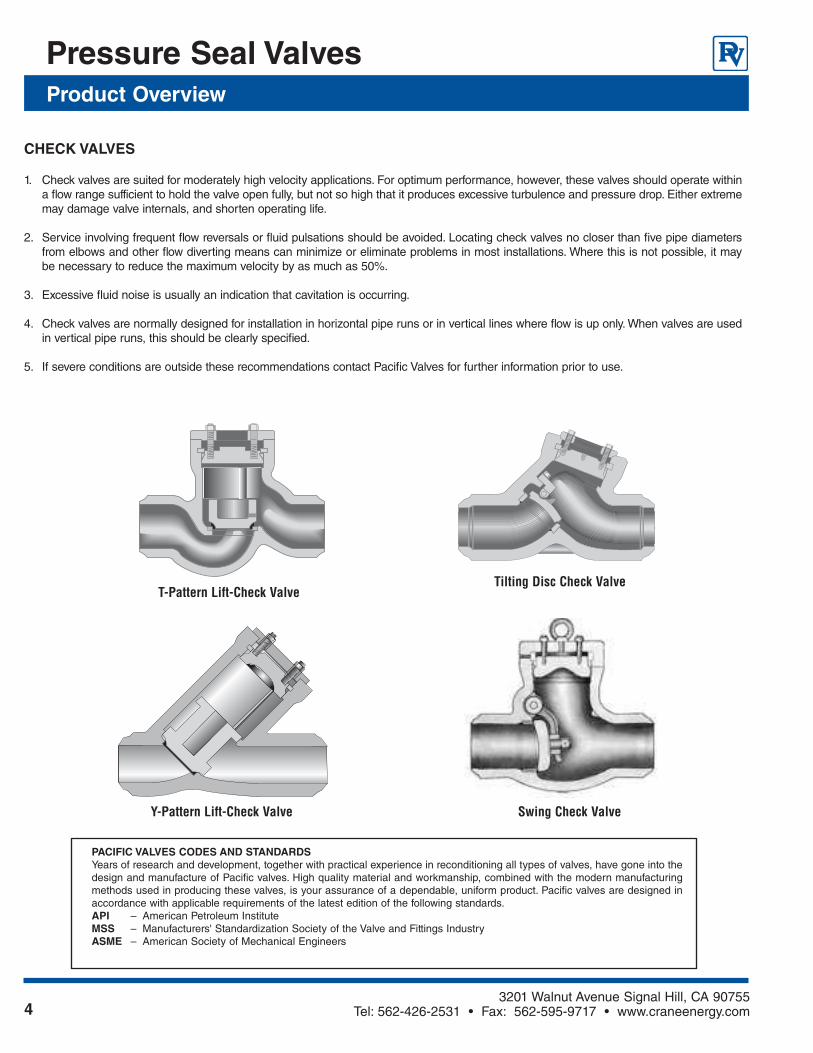
1. Check valves are suited for moderately high velocity applications. For optimum performance, however, these valves should operate within
may damage valve internals, and shorten operating life.
2. Service involving frequent "ow reversals or "uid pulsations should be avoided. Locating check valves no closer than !ve pipe diameters
from elbows and other "ow diverting means can minimize or eliminate problems in most installations. Where this is not possible, it may
4. Check valves are normally designed for installation in horizontal pipe runs or in vertical lines where "ow is up only. When valves are used
in vertical pipe runs, this should be clearly speci!ed.
5. If severe conditions are outside these recommendations contact Paci!c Valves for further information prior to use.
Product Overview
CHECK VALVES
PACIFIC VALVES CODES AND STANDARDS
design and manufacture of Paci!c valves. High quality material and workmanship, combined with the modern manufacturing
methods used in producing these valves, is your assurance of a dependable, uniform product. Paci!c valves are designed in
accordance with applicable requirements of the latest edition of the following standards.
API – American Petroleum Institute
MSS – Manufacturers' Standardization Society of the Valve and Fittings Industry
ASME – American Society of Mechanical Engineers
T-Pattern Lift-Check ValveTilting Disc Check Valve
Y-Pattern Lift-Check Valve Swing Check Valve
3201 Walnut Avenue Signal Hill, CA 90755
Pressure Seal Valves
17
16B
30
71
11
43
55
98
124
10
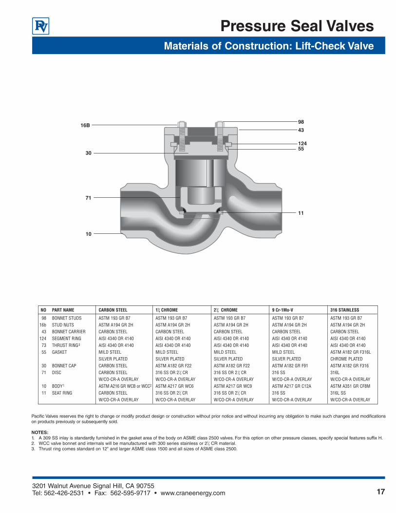
NO PART NAME CARBON STEEL 11⁄4 CHROME 21⁄4 CHROME 9 Cr-1Mo-V 316 STAINLESS
98 BONNET STUDS ASTM 193 GR B7 ASTM 193 GR B7 ASTM 193 GR B7 ASTM 193 GR B7 ASTM 193 GR B7
16b STUD NUTS ASTM A194 GR 2H ASTM A194 GR 2H ASTM A194 GR 2H ASTM A194 GR 2H ASTM A194 GR 2H
43 BONNET CARRIER CARBON STEEL CARBON STEEL CARBON STEEL CARBON STEEL CARBON STEEL
124 SEGMENT RING AISI 4340 OR 4140 AISI 4340 OR 4140 AISI 4340 OR 4140 AISI 4340 OR 4140 AISI 4340 OR 4140
73 THRUST RING3 AISI 4340 OR 4140 AISI 4340 OR 4140 AISI 4340 OR 4140 AISI 4340 OR 4140 AISI 4340 OR 4140
55 GASKET MILD STEEL MILD STEEL MILD STEEL MILD STEEL ASTM A182 GR F316L
SILVER PLATED SILVER PLATED SILVER PLATED SILVER PLATED CHROME PLATED
30 BONNET CAP CARBON STEEL ASTM A182 GR F22 ASTM A182 GR F22 ASTM A182 GR F91 ASTM A182 GR F316
71 DISC CARBON STEEL 316 SS OR 21⁄4 CR 316 SS OR 2 1⁄4 CR 316 SS 316L
W/CO-CR-A OVERLAY W/CO-CR-A OVERLAY W/CO-CR-A OVERLAY W/CO-CR-A OVERLAY W/CO-CR-A OVERLAY
10 BODY1 ASTM A216 GR WCB or WCC2 ASTM A217 GR WC6 ASTM A217 GR WC9 ASTM A217 GR C12A ASTM A351 GR CF8M
11 SEAT RING CARBON STEEL 316 SS OR 21⁄4 CR 316 SS OR 21⁄4 CR 316 SS 316L SS
W/CO-CR-A OVERLAY W/CO-CR-A OVERLAY W/CO-CR-A OVERLAY W/CO-CR-A OVERLAY W/CO-CR-A OVERLAY
Materials of Construction: Lift-Check Valve
Paci!c Valves reserves the right to change or modify product design or construction without prior notice and without incurring any obligation to make such changes and modi!cations
on products previously or subsequently sold.
NOTES:
2. WCC valve bonnet and internals will be manufactured with 300 series stainless or 21⁄4 CR material.
3. Thrust ring comes standard on 12" and larger ASME class 1500 and all sizes of ASME class 2500.

3201 Walnut Avenue Signal Hill, CA 9075518
Pressure Seal Valves
in. 12 12 12 14 20 26 31 36 39
mm 304 304 304 355 508 660 787 914 990
in. N/A N/A 15 18 24 29 33 38 40.5
mm N/A N/A 381 457 609 736 838 965 1028
in. N/A N/A 15.13 18.13 24.13 29.13 33.13 38.13 40.88
mm N/A N/A 384 460 612 739 841 968 1039
in. 6 6 6 7 12 15 17 21 24
mm 152 152 152 184 292 381 425 533 603
lbs 49 49 49 103 299 588 978 1517 2036
kg 22 22 22 46 135 266 443 688 923
lbs N/A N/A 109 180 324 948 1425 2165 3082
kg N/A N/A 49 82 147 430 646 982 1398
A
A1
A2
K
End to EndWeld Ends
Face to FaceFlanged Ends
Face to FaceRTJ
Center to TopOpen
WeightWeld Ends
WeightFlanged Ends
VALVE SIZES (inches)
NOTE:
1. Integral body seat on 2" through 4".
Dim Description 2 2.5 3 4 6 8 10 12 14
A
K
in. 24 29 33 38 40.5
mm 609 736 838 965 1028
in. 12 15 17 21 24
mm 292 381 425 533 603
lbs 303 602 1003 1549 2076
kg 137 373 455 702 941
End to End
Center to TopOpen
Weight
Dim Description 8x6x8 10x8x10 12x10x12 14x12x14 16x14x16
VALVE SIZES (inches)
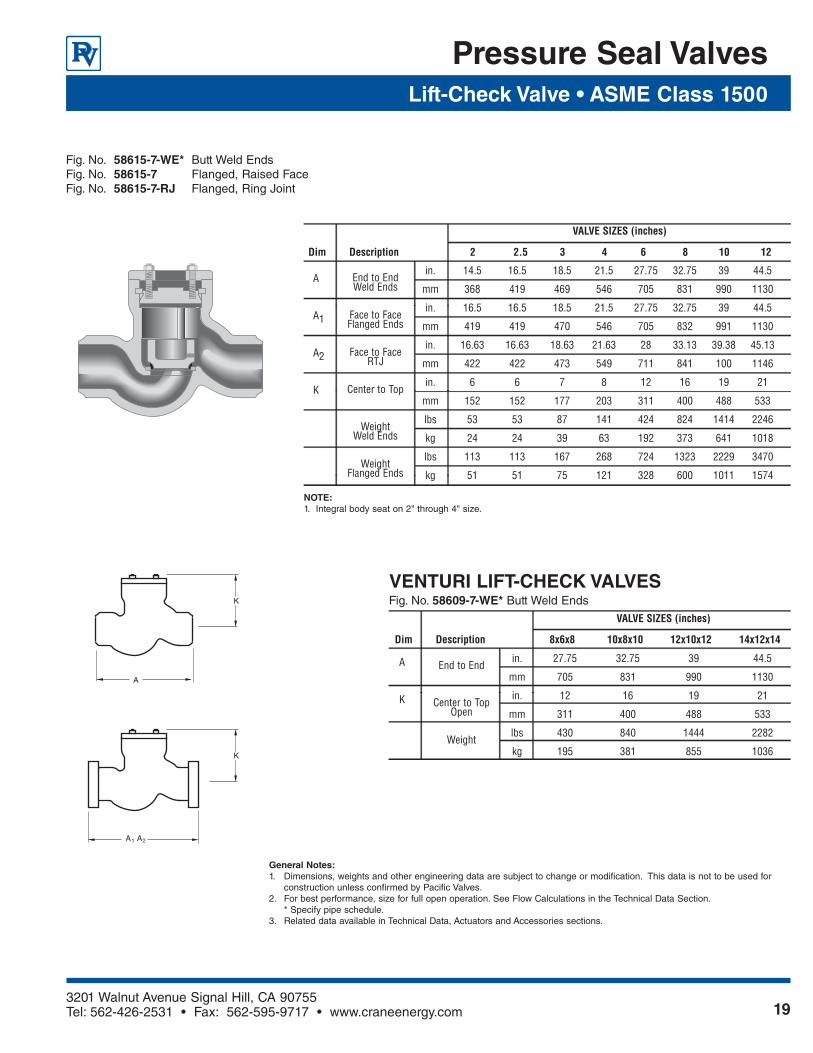
Fig. No. 58615-7-WE* Butt Weld Ends
VENTURI LIFT-CHECK VALVES
General Notes:
1. Dimensions, weights and other engineering data are subject to change or modi!cation. This data is not to be used for
construction unless con!rmed by Paci!c Valves.
2. For best performance, size for full open operation. See Flow Calculations in the Technical Data Section.
* Specify pipe schedule.
3. Related data available in Technical Data, Actuators and Accessories sections.
Fig. No. 58609-7-WE* Butt Weld Ends
Fig. No. 58609-7 Flanged, Raised Face
Fig. No. 58609-7-RJ
K
A
K
A A21
3201 Walnut Avenue Signal Hill, CA 90755
Pressure Seal Valves
19
Fig. No. 58615-7-WE* Butt Weld Ends
Fig. No. 58615-7 Flanged, Raised Face
Fig. No. 58615-7-RJ
A
A1
A2
K
VALVE SIZES (inches)
End to EndWeld Ends
Face to FaceFlanged Ends
Face to FaceRTJ
Center to Top
Weight
Weld Ends
WeightFlanged Ends
in. 14.5 16.5 18.5 21.5 27.75 32.75 39 44.5
mm 368 419 469 546 705 831 990 1130
in. 16.5 16.5 18.5 21.5 27.75 32.75 39 44.5
mm 419 419 470 546 705 832 991 1130
in. 16.63 16.63 18.63 21.63 28 33.13 39.38 45.13
mm 422 422 473 549 711 841 100 1146
in. 6 6 7 8 12 16 19 21
mm 152 152 177 203 311 400 488 533
lbs 53 53 87 141 424 824 1414 2246
kg 24 24 39 63 192 373 641 1018
lbs 113 113 167 268 724 1323 2229 3470
kg 51 51 75 121 328 600 1011 1574
NOTE:
1. Integral body seat on 2" through 4" size.
Dim Description 2 2.5 3 4 6 8 10 12
General Notes:
1. Dimensions, weights and other engineering data are subject to change or modi!cation. This data is not to be used for
construction unless con!rmed by Paci!c Valves.
2. For best performance, size for full open operation. See Flow Calculations in the Technical Data Section.
* Specify pipe schedule.
3. Related data available in Technical Data, Actuators and Accessories sections.
VALVE SIZES (inches)
Dim Description 8x6x8 10x8x10 12x10x12 14x12x14
A
K
End to End
Center to TopOpen
Weight
in. 27.75 32.75 39 44.5
mm 705 831 990 1130
in. 12 16 19 21
mm 311 400 488 533
lbs 430 840 1444 2282
kg 195 381 855 1036
Fig. No. 58609-7-WE* Butt Weld Ends
VENTURI LIFT-CHECK VALVESK
A
K
A A21
3201 Walnut Avenue Signal Hill, CA 9075520
Pressure Seal Valves
A
A1
A2
K
VALVE SIZES (inches)
End to EndWeld Ends
Face to FaceFlanged Ends
Face to FaceRTJ
Center to Top
Weight
Weld Ends
WeightFlanged Ends
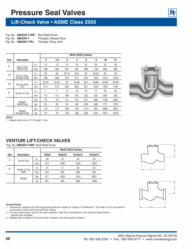
in. 13 13 15 18 24 29 33 38
mm 330 330 381 457 609 736 838 965
in. 20 20 22.75 26.5 36 40.25 50 56
mm 508 508 578 673 914 1022 1270 1422
in. 20.25 20.25 23 26.88 36.5 40.88 50.88 56.88
mm 514 514 584 683 927 1039 1293 1445
in. 7 7 8 10 13 17 20 22
mm 171 171 196 241 323 425 508 552
lbs 78 78 121 151 527 900 1700 2801
kg 35 35 55 68 239 408 771 1270
lbs 173 173 298 416 1214 1937 3689 5901
kg 78 78 135 189 550 878 1673 2676
NOTE:
1. Integral body seat on 2" through 3" size.
VALVE SIZES (inches)
in. 36 43 49 64
mm 914 1092 1244 1625
in. 13 17 20 22
mm 323 425 508 552
lbs 577 1035 1914 3061
kg 261 469 868 1388
Fig. No. 58625H-7-WE* Butt Weld Ends
VENTURI LIFT-CHECK VALVES
End to End
Center to TopOpen
Weight
Dim Description 8x6x8 10x8x10 12x10x12 14x12x14
A
K
General Notes:
1. Dimensions, weights and other engineering data are subject to change or modi!cation. This data is not to be used for
construction unless con!rmed by Paci!c Valves.
2. For best performance, size for full open operation. See Flow Calculations in the Technical Data Section.
* Specify pipe schedule.
3. Related data available in Technical Data, Actuators and Accessories sections.
Fig. No. 58625H-7-WE* Butt Weld Ends
Fig. No. 58625H-7 Flanged, Raised Face
Fig. No. 58625H-7-RJ
K
A
K
A A21
Dim Description 2 2.5 3 4 6 8 10 12
3201 Walnut Avenue Signal Hill, CA 90755
Pressure Seal Valves
27
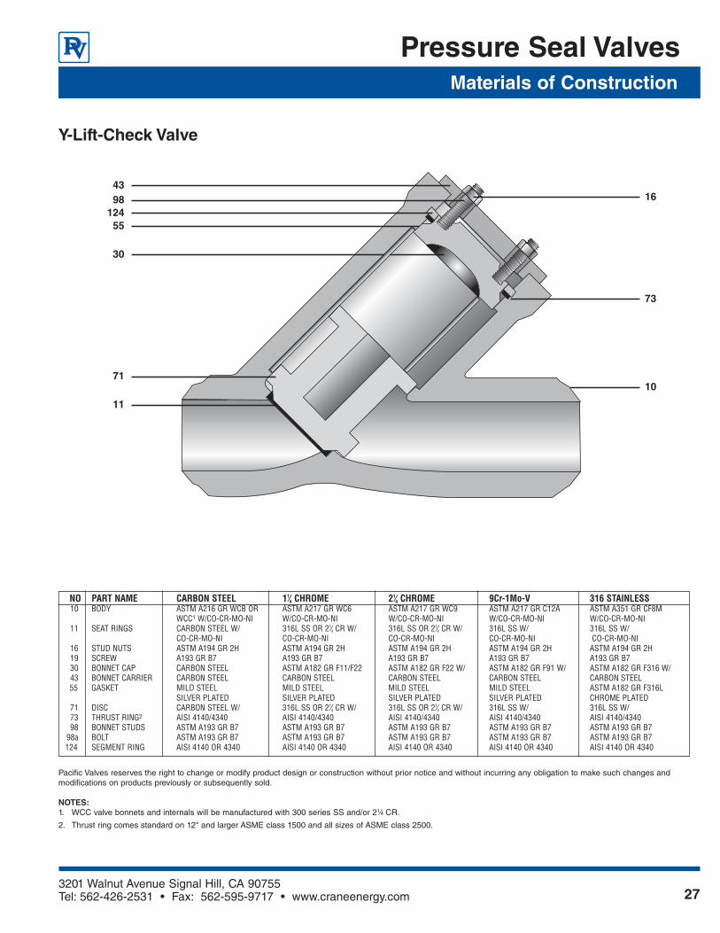
NO PART NAME CARBON STEEL 11⁄4 CHROME 21⁄4 CHROME 9Cr-1Mo-V 316 STAINLESS 10 BODY ASTM A216 GR WCB OR ASTM A217 GR WC6 ASTM A217 GR WC9 ASTM A217 GR C12A ASTM A351 GR CF8M WCC1 W/CO-CR-MO-NI W/CO-CR-MO-NI W/CO-CR-MO-NI W/CO-CR-MO-NI W/CO-CR-MO-NI 11 SEAT RINGS CARBON STEEL W/ 316L SS OR 21⁄4 CR W/ 316L SS OR 21⁄4 CR W/ 316L SS W/ 316L SS W/ CO-CR-MO-NI CO-CR-MO-NI CO-CR-MO-NI CO-CR-MO-NI CO-CR-MO-NI 16 STUD NUTS ASTM A194 GR 2H ASTM A194 GR 2H ASTM A194 GR 2H ASTM A194 GR 2H ASTM A194 GR 2H 19 SCREW A193 GR B7 A193 GR B7 A193 GR B7 A193 GR B7 A193 GR B7 30 BONNET CAP CARBON STEEL ASTM A182 GR F11/F22 ASTM A182 GR F22 W/ ASTM A182 GR F91 W/ ASTM A182 GR F316 W/ 43 BONNET CARRIER CARBON STEEL CARBON STEEL CARBON STEEL CARBON STEEL CARBON STEEL 55 GASKET MILD STEEL MILD STEEL MILD STEEL MILD STEEL ASTM A182 GR F316L SILVER PLATED SILVER PLATED SILVER PLATED SILVER PLATED CHROME PLATED 71 DISC CARBON STEEL W/ 316L SS OR 21⁄4 CR W/ 316L SS OR 21⁄4 CR W/ 316L SS W/ 316L SS W/ 73 THRUST RING2 AISI 4140/4340 AISI 4140/4340 AISI 4140/4340 AISI 4140/4340 AISI 4140/4340 98 BONNET STUDS ASTM A193 GR B7 ASTM A193 GR B7 ASTM A193 GR B7 ASTM A193 GR B7 ASTM A193 GR B7 98a BOLT ASTM A193 GR B7 ASTM A193 GR B7 ASTM A193 GR B7 ASTM A193 GR B7 ASTM A193 GR B7 124 SEGMENT RING AISI 4140 OR 4340 AISI 4140 OR 4340 AISI 4140 OR 4340 AISI 4140 OR 4340 AISI 4140 OR 4340
Paci!c Valves reserves the right to change or modify product design or construction without prior notice and without incurring any obligation to make such changes and
modi!cations on products previously or subsequently sold.
NOTES:
1. WCC valve bonnets and internals will be manufactured with 300 series SS and/or 2¼ CR.
2. Thrust ring comes standard on 12" and larger ASME class 1500 and all sizes of ASME class 2500.
Materials of Construction
Y-Lift-Check Valve
431698
124
55
30
71
11
10
73
3201 Walnut Avenue Signal Hill, CA 9075528
Pressure Seal Valves
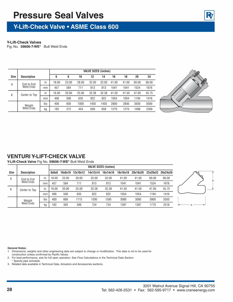
Y-Lift-Check ValvesFig. No. 59606-7-WE* Butt Weld Ends
K
A
End to EndWeld Ends
Center to Top
WeightWeld Ends
in 18.00 23.00 28.00 32.00 32.00 41.00 41.00 60.00 66.00
mm 457 584 711 813 813 1041 1041 1524 1676
in 16.00 20.00 25.00 32.38 32.38 41.50 41.50 47.00 55.75
mm 406 508 635 822 822 1054 1054 1194 1416
lbs 400 600 1000 1450 1450 2800 2800 3500 5000
kg 182 272 454 658 658 1270 1270 1588 2269
A
K
Dim Description 6 8 10 12 14 16 18 20 24
End to EndWeld Ends
Center to Top
WeightWeld Ends
VALVE SIZES (inches)
VALVE SIZES (inches)
A
K
VENTURI Y-LIFT-CHECK VALVEY-Lift-Check Valve Fig No. 59606-7-WE* Butt Weld Ends
General Notes:
1. Dimensions, weights and other engineering data are subject to change or modi!cation. This data is not to be used for
construction unless con!rmed by Paci!c Valves.
2. For best performance, size for full open operation. See Flow Calculations in the Technical Data Section.
* Specify pipe schedule.
3. Related data available in Technical Data, Actuators and Accessories sections.
in. 18.00 23.00 28.00 32.00 32.00 41.00 41.00 60.00 66.00
mm 457 584 711 813 813 1041 1041 1524 1676
in. 16.00 20.00 25.00 32.38 32.38 41.50 41.50 47.00 55.75
mm 406 508 635 822 822 1054 1054 1194 1416
lbs 400 668 1115 1595 1595 3080 3080 3900 5550
kg 182 303 506 724 724 1397 1397 1770 2518
Dim Description 8x6x8 10x8x10 12x10x12 14x12x14 16x14x16 18x16x18 20x18x20 22x20x22 26x24x26
3201 Walnut Avenue Signal Hill, CA 90755
Pressure Seal Valves
29
End to EndWeld Ends
Center to Top
WeightWeld Ends
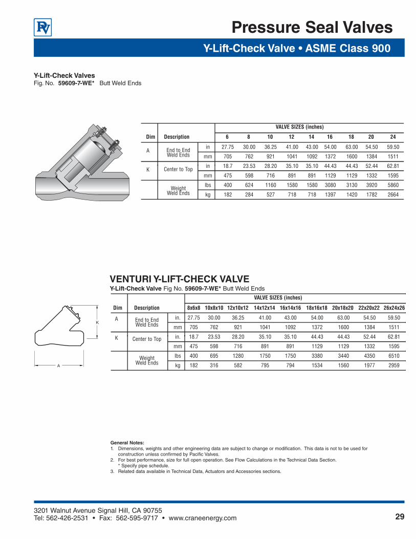
in 27.75 30.00 36.25 41.00 43.00 54.00 63.00 54.50 59.50
mm 705 762 921 1041 1092 1372 1600 1384 1511
in 18.7 23.53 28.20 35.10 35.10 44.43 44.43 52.44 62.81
mm 475 598 716 891 891 1129 1129 1332 1595
lbs 400 624 1160 1580 1580 3080 3130 3920 5860
kg 182 284 527 718 718 1397 1420 1782 2664
Y-Lift-Check ValvesFig. No. 59609-7-WE* Butt Weld Ends
A
K
Dim Description 6 8 10 12 14 16 18 20 24
End to EndWeld Ends
Center to Top
WeightWeld Ends
VALVE SIZES (inches)
VALVE SIZES (inches)
A
K
VENTURI Y-LIFT-CHECK VALVEY-Lift-Check Valve Fig No. 59609-7-WE* Butt Weld Ends
General Notes:
1. Dimensions, weights and other engineering data are subject to change or modi!cation. This data is not to be used for
construction unless con!rmed by Paci!c Valves.
2. For best performance, size for full open operation. See Flow Calculations in the Technical Data Section.
* Specify pipe schedule.
3. Related data available in Technical Data, Actuators and Accessories sections.
K
A
in. 27.75 30.00 36.25 41.00 43.00 54.00 63.00 54.50 59.50
mm 705 762 921 1041 1092 1372 1600 1384 1511
in. 18.7 23.53 28.20 35.10 35.10 44.43 44.43 52.44 62.81
mm 475 598 716 891 891 1129 1129 1332 1595
lbs 400 695 1280 1750 1750 3380 3440 4350 6510
kg 182 316 582 795 794 1534 1560 1977 2959
Dim Description 8x6x8 10x8x10 12x10x12 14x12x14 16x14x16 18x16x18 20x18x20 22x20x22 26x24x26
3201 Walnut Avenue Signal Hill, CA 9075530
Pressure Seal Valves
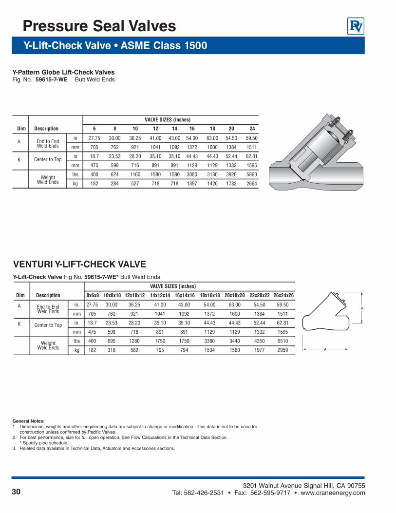
Y-Pattern Globe Lift-Check ValvesFig. No. 59615-7-WE Butt Weld Ends
General Notes:
1. Dimensions, weights and other engineering data are subject to change or modi!cation. This data is not to be used for
construction unless con!rmed by Paci!c Valves.
2. For best performance, size for full open operation. See Flow Calculations in the Technical Data Section.
* Specify pipe schedule.
3. Related data available in Technical Data, Actuators and Accessories sections.
in 27.75 30.00 36.25 41.00 43.00 54.00 63.00 54.50 59.50
mm 705 762 921 1041 1092 1372 1600 1384 1511
in 18.7 23.53 28.20 35.10 35.10 44.43 44.43 52.44 62.81
mm 475 598 716 891 891 1129 1129 1332 1595
lbs 400 624 1160 1580 1580 3080 3130 3920 5860
kg 182 284 527 718 718 1397 1420 1782 2664
A
K
Dim Description 6 8 10 12 14 16 18 20 24
End to EndWeld Ends
Center to Top
WeightWeld Ends
VALVE SIZES (inches)
End to EndWeld Ends
Center to Top
WeightWeld Ends
VALVE SIZES (inches)
A
K
VENTURI Y-LIFT-CHECK VALVE
Y-Lift-Check Valve Fig No. 59615-7-WE* Butt Weld Ends
in. 27.75 30.00 36.25 41.00 43.00 54.00 63.00 54.50 59.50
mm 705 762 921 1041 1092 1372 1600 1384 1511
in. 18.7 23.53 28.20 35.10 35.10 44.43 44.43 52.44 62.81
mm 475 598 716 891 891 1129 1129 1332 1595
lbs 400 695 1280 1750 1750 3380 3440 4350 6510
kg 182 316 582 795 794 1534 1560 1977 2959
Dim Description 8x6x8 10x8x10 12x10x12 14x12x14 16x14x16 18x16x18 20x18x20 22x20x22 26x24x26
K
A

3201 Walnut Avenue Signal Hill, CA 90755
Pressure Seal Valves
31
in. 30.00 30.00 36.00 41.00 48.75 48.75 58.00 58.00 68.00
mm 762 762 914 1041 1238 1238 1473 1473 1727
in. 24.11 24.11 29.95 34.60 37.33 37.33 47.44 47.44 50.56
mm. 612 612 761 879 948 95 1205 1205 1284
lbs 660 660 1180 1898 3040 3040 4750 4650 7000
kg 300 300 585 863 1380 1380 2159 2159 3176
Y-Lift-Check ValvesFig. No. 59625H-7-WE* Butt Weld Ends
A
K
Dim Description 6 8 10 12 14 16 18 20 24
End to EndWeld Ends
Center to Top
WeightWeld Ends
VALVE SIZES (inches)
VENTURI Y-LIFT-CHECK VALVEY-Lift-Check Valve Fig. No. 59625H-7-WE* Butt Weld Ends
General Notes:
1. Dimensions, weights and other engineering data are subject to change or modi!cation. This data is not to be used for
construction unless con!rmed by Paci!c Valves.
2. For best performance, size for full open operation. See Flow Calculations in the Technical Data Section.
* Specify pipe schedule.
3. Related data available in Technical Data, Actuators and Accessories sections.
K
A
End to EndWeld Ends
Center to Top
WeightWeld Ends
VALVE SIZES (inches)
A
K
in. 30.00 30.00 36.00 41.00 48.75 48.75 58.00 58.00 68.00
mm 762 762 914 1041 1238 1238 1473 1473 1727
in. 24.11 24.11 29.95 34.60 37.33 37.33 47.44 47.44 50.56
mm 612 612 761 879 948 95 1205 1205 1284
lbs 725 725 1310 2110 3375 3375 5275 5272 7770
kg 329 329 594 959 1530 1530 2398 2392 3525
Dim Description 8x6x8 10x8x10 12x10x12 14x12x14 16x14x16 18x16x18 20x18x20 22x20x22 26x24x26
3201 Walnut Avenue Signal Hill, CA 9075532
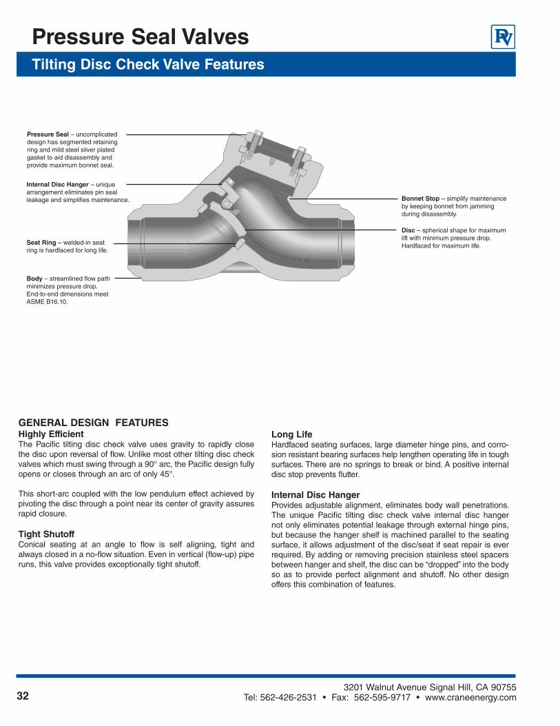
Pressure Seal ValvesTilting Disc Check Valve Features
Pressure Seal – uncomplicated
design has segmented retaining
ring and mild steel silver plated
gasket to aid disassembly and
pro
Internal Disc Hanger – unique
arrangement eliminates pin seal
leakage and simplifies maintenance.
Seat Ring – welded-in seat
ring is hardfaced for long life.
Body – streamlined flow path
minimizes pressure drop.
End-to-end dimensions meet
ASME B16.10.
Disc – spherical shape f
lift with minimum pressure drop.
Hardfaced f e.
Bonnet Stop – simplify maintenance
by keeping bonnet from jamming
during disassembly.
GENERAL DESIGN FEATURESHighly EfficientThe Paci!c tilting disc check valve uses gravity to rapidly close
the disc upon reversal of "ow. Unlike most other tilting disc check
valves which must swing through a 90° arc, the Paci!c design fully
opens or closes through an arc of only 45°.
This short-arc coupled with the low pendulum effect achieved by
pivoting the disc through a point near its center of gravity assures
rapid closure.
Tight ShutoffConical seating at an angle to "ow is self aligning, tight and
always closed in a no-"ow situation. Even in vertical ("ow-up) pipe
Long LifeHardfaced seating surfaces, large diameter hinge pins, and corro-
sion resistant bearing surfaces help lengthen operating life in tough
surfaces. There are no springs to break or bind. A positive internal
disc stop prevents "utter.
Internal Disc HangerProvides adjustable alignment, eliminates body wall penetrations.
The unique Paci!c tilting disc check valve internal disc hanger
but because the hanger shelf is machined parallel to the seating
surface, it allows adjustment of the disc/seat if seat repair is ever
required. By adding or removing precision stainless steel spacers
between hanger and shelf, the disc can be “dropped” into the body
so as to provide perfect alignment and shutoff. No other design
offers this combination of features.
3201 Walnut Avenue Signal Hill, CA 90755
Pressure Seal Valves
33
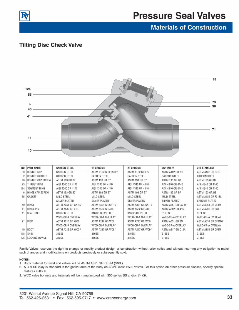
Materials of Construction
124
55
6
40
41
11
10
30
73
71
98
Paci!c Valves reserves the right to change or modify product design or construction without prior notice and without incurring any obligation to make
such changes and modi!cations on products previously or subsequently sold.
NOTES:
1. Body material for weld end valves will be ASTM A351 GR CF3M (316L).
2. A 309 SS inlay is standard in the gasket area of the body on ASME class 2500 valves. For this option on other pressure classes, specify special
3. WCC valve bonnets and internals will be manufactured with 300 series SS and/or 2¼ CR.
Tilting Disc Check Valve
NO PART NAME CARBON STEEL 11⁄4 CHROME 21⁄4 CHROME 9Cr-1Mo-V 316 STAINLESS
30 BONNET CAP CARBON STEEL ASTM A182 GR F11/F22 ASTM A182 GR F22 ASTM A182 GRF91 ASTM A182 GR F316
2 BONNET CARRIER CARBON STEEL CARBON STEEL CARBON STEEL CARBON STEEL CARBON STEEL
98 BONNET CAP SCREW ASTM 193 GR B7 ASTM 193 GR B7 ASTM 193 GR B7 ASTM 193 GR B7 ASTM 193 GR B7
73 THRUST RING AISI 4340 OR 4140 AISI 4340 OR 4140 AISI 4340 OR 4140 AISI 4340 OR 4140 AISI 4340 OR 4140
124 SEGMENT RING AISI 4340 OR 4140 AISI 4340 OR 4140 AISI 4340 OR 4140 AISI 4340 OR 4140 AISI 4340 OR 4140
6 HINGE CAP SCREW ASTM 193 GR B7 ASTM 193 GR B7 ASTM 193 GR B7 ASTM 193 GR B7 ASTM 193 GR B8
55 GASKET MILD STEEL MILD STEEL MILD STEEL MILD STEEL ASTM A182 GR F316L
SILVER PLATED SILVER PLATED SILVER PLATED SILVER PLATED CHROME PLATED
40 HINGE ASTM A351 GR CA-15 ASTM A351 GR CA-15 ASTM A351 GR CA-15 ASTM A351 GR CA-15 ASTM A351 GR CF8M
41 HINGE PIN ASTM A582 GR 416 ASTM A582 GR 416 ASTM A582 GR 416 ASTM A582 GR 416 ASTM A705 GR 630
11 SEAT RING CARBON STEEL 316 SS OR 21⁄4 CR 316 SS OR 21⁄4 CR 316 SS 316L SS
W/CO-CR-A OVERLAY W/CO-CR-A OVERLAY W/CO-CR-A OVERLAY W/CO-CR-A OVERLAY W/CO-CR-A OVERLAY
71 DISC ASTM A216 GR WCB ASTM A217 GR WC6 ASTM A217 GR WC9 ASTM A351 GR 8M ASTM A351 GR CF8MW
W/CO-CR-A OVERLAY W/CO-CR-A OVERLAY W/CO-CR-A OVERLAY W/CO-CR-A OVERLAY W/CO-CR-A OVERLAY
10 BODY ASTM A216 GR WCC3 ASTM A217 GR WC62 ASTM A217 GR WC92 ASTM A217 GR C12A ASTM A351 GR CF8M
118 SHIM 316SS 316SS 316SS 316SS 316SS
126 LOCKING DEVICE 316SS 316SS 316SS 316SS 316SS

3201 Walnut Avenue Signal Hill, CA 9075534
Pressure Seal Valves
A
A1
A2
K
End to EndWeld Ends
Face to FaceFlanged Ends
Face to FaceRTJ
Center to Top
Weight
Weld Ends
WeightFlange Ends
Fig. No. 58809-7-WE* Butt Weld Ends
Fig. No. 58809-7 Flanged, Raised Face
Fig. No. 58809-7-RJ
A
K
End to End
Center to TopOpen
Weight
in. 24 29 33 38 40.5 44.5 48
mm 609 736 838 965 1028 1130 1219
in. 9.5 12 15 16.5 18 19.75 23.5
mm 241 304 381 419 457 501 596
lbs 140 250 485 740 930 1350 1890
kg 63 113 219 335 421 612 857
Dim Description 8x6x8 10x8x10 12x10x12 14x12x14 16x14x16 18x16x18 20x18x20
VALVE SIZES (inches)
General Notes:
1. Dimensions, weights and other engineering data are subject to change or modi!cation. This data is not to be used for
construction unless con!rmed by Paci!c Valves.
2. For best performance, size for full open operation. See Flow Calculations in the Technical Data Section.
* Specify pipe schedule.
3. Related data available in Technical Data, Actuators and Accessories sections.
Fig. No. 58809-7-WE* Butt Weld Ends
VENTURI TILTING DISC CHECK VALVESK
A A21
A
K
Dim Description 2 2.5 3 4 6 8 10 12 14 16 18 20 24
VALVE SIZES (inches)
in. 10 10 12 14 20 26 31 36 39 43 48 52 61
mm 254 254 304 355 508 660 787 914 990 1092 1219 1320 1549
in. N/A N/A 15 18 24 19 33 38 40.5 44.5 48 52 61
mm N/A N/A 381 457 609 736 838 965 1028 1130 1219 1320 1549
in. N/A N/A 15.13 18.13 24.13 29.13 33.13 38.13 40.88 44.88 48.5 52.5 61.75
mm N/A N/A 384 460 612 739 841 968 1039 1140 1232 1333 1568
in. 7.5 7.5 7.5 7.5 9.5 12 15 16.5 18 19.75 23.5 26 31
mm 190 190 190 190 241 304 381 419 457 501 596 660 787
lbs 45 45 45 50 130 240 470 720 900 1300 1840 2430 4200
kg 20 20 20 23 59 109 213 326 408 589 834 1102 1905
lbs N/A N/A 110 150 350 610 1000 1460 2000 2600 3650 4725 8400
kg N/A N/A 50 68 159 276 473 662 907 1179 1655 2143 3809
3201 Walnut Avenue Signal Hill, CA 90755
Pressure Seal Valves
35
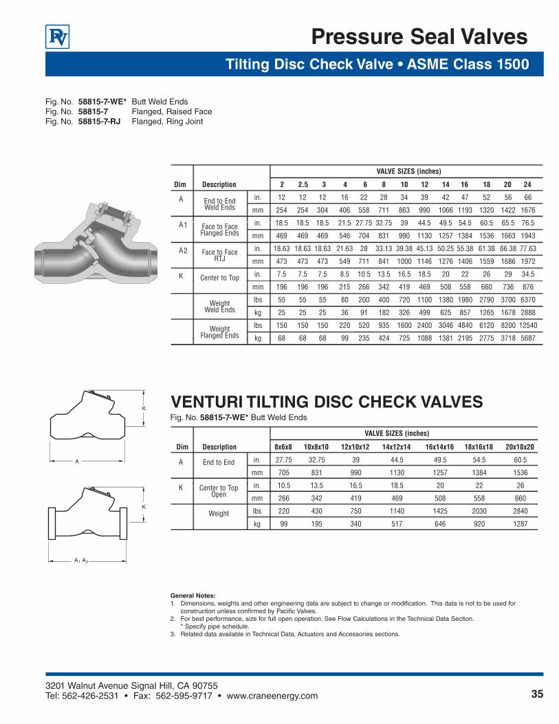
Fig. No. 58815-7-WE* Butt Weld Ends
Fig. No. 58815-7 Flanged, Raised Face
Fig. No. 58815-7-RJ
VALVE SIZES (inches)
A
A1
A2
K
End to EndWeld Ends
Face to FaceFlanged Ends
Face to FaceRTJ
Center to Top
Weight
Weld Ends
WeightFlanged Ends
in. 12 12 12 16 22 28 34 39 42 47 52 56 66
mm 254 254 304 406 558 711 863 990 1066 1193 1320 1422 1676
in. 18.5 18.5 18.5 21.5 27.75 32.75 39 44.5 49.5 54.5 60.5 65.5 76.5
mm 469 469 469 546 704 831 990 1130 1257 1384 1536 1663 1943
in. 18.63 18.63 18.63 21.63 28 33.13 39.38 45.13 50.25 55.38 61.38 66.38 77.63
mm 473 473 473 549 711 841 1000 1146 1276 1406 1559 1686 1972
in. 7.5 7.5 7.5 8.5 10.5 13.5 16.5 18.5 20 22 26 29 34.5
mm 196 196 196 215 266 342 419 469 508 558 660 736 876
lbs 55 55 55 80 200 400 720 1100 1380 1980 2790 3700 6370
kg 25 25 25 36 91 182 326 499 625 857 1265 1678 2888
lbs 150 150 150 220 520 935 1600 2400 3046 4840 6120 8200 12540
kg 68 68 68 99 235 424 725 1088 1381 2195 2775 3718 5687
A
K
End to End
Center to TopOpen
Weight
Dim Description 8x6x8 10x8x10 12x10x12 14x12x14 16x14x16 18x16x18 20x18x20
VALVE SIZES (inches)
in. 27.75 32.75 39 44.5 49.5 54.5 60.5
mm 705 831 990 1130 1257 1384 1536
in. 10.5 13.5 16.5 18.5 20 22 26
mm 266 342 419 469 508 558 660
lbs 220 430 750 1140 1425 2030 2840
kg 99 195 340 517 646 920 1287
General Notes:
1. Dimensions, weights and other engineering data are subject to change or modi!cation. This data is not to be used for
construction unless con!rmed by Paci!c Valves.
2. For best performance, size for full open operation. See Flow Calculations in the Technical Data Section.
* Specify pipe schedule.
3. Related data available in Technical Data, Actuators and Accessories sections.
Fig. No. 58815-7-WE* Butt Weld Ends
VENTURI TILTING DISC CHECK VALVESK
A A21
A
K
Dim Description 2 2.5 3 4 6 8 10 12 14 16 18 20 24
3201 Walnut Avenue Signal Hill, CA 9075536
Pressure Seal Valves
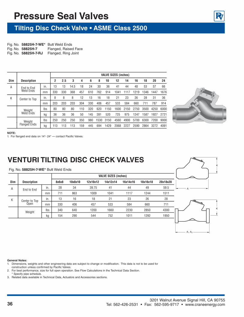
Fig. No. 58825H-7-WE* Butt Weld Ends
Fig. No. 58825H-7 Flanged, Raised Face
Fig. No. 58825H-7-RJ
VALVE SIZES (inches)
End to End
Center to TopOpen
Weight
A
K
Fig. No. 58825H-7-WE* Butt Weld Ends
Dim Description 8x6x8 10x8x10 12x10x12 14x12x14 16x14x16 18x16x18 20x18x20
in. 28 34 39.75 41 44 49 59.5
mm 711 863 1009 1041 1117 1244 1511
in. 13 16 18 21 23 26 28
mm 330 406 457 533 584 660 711
lbs 340 640 1200 1660 2230 2850 4300
kg 154 290 544 752 1011 1292 1950
VALVE SIZES (inches)
VENTURI TILTING DISC CHECK VALVES
General Notes:
1. Dimensions, weights and other engineering data are subject to change or modi!cation. This data is not to be used for
construction unless con!rmed by Paci!c Valves.
2. For best performance, size for full open operation. See Flow Calculations in the Technical Data Section.
* Specify pipe schedule.
3. Related data available in Technical Data, Actuators and Accessories sections.
K
A A21
A
K
Dim Description 2 2.5 3 4 6 8 10 12 14 16 18 20 24
A
K
End to EndWeld Ends
Center to Top
Weight
Weld Ends
WeightFlanged Ends
in. 13 13 14.5 18 24 30 36 41 44 48 53 57 66
mm 330 330 368 457 610 762 914 1041 1117 1219 1346 1447 1676
in. 8 8 8 12 13 16 18 21 23 26 28 31 36
mm 203 203 203 304 330 406 457 533 584 660 711 787 914
lbs 80 80 80 110 320 620 1150 1600 2150 2750 3500 4250 6000
kg 36 36 36 50 145 281 520 725 975 1247 1587 1927 2721
lbs 250 250 250 350 980 1530 3150 4560 4900 5700 6300 7200 9000
kg 113 113 113 159 445 694 1429 2068 2227 2590 2864 3272 4091
NOTE:
1. For "anged end data on 14"- 24" — contact Paci!c Valves.
3201 Walnut Avenue Signal Hill, CA 90755
Pressure Seal Valves
37
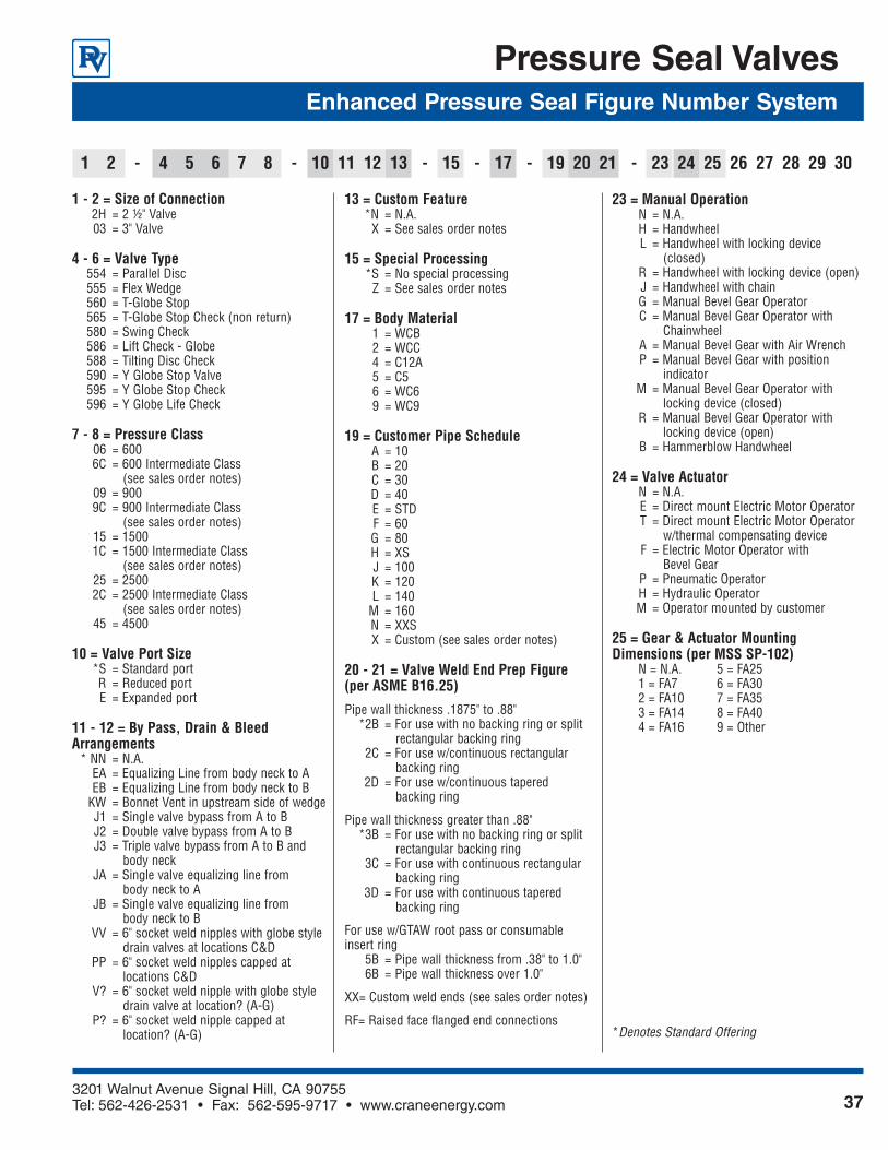
Enhanced Pressure Seal Figure Number System
1 2 - 4 5 6 7 8 - 10 11 12 13 - 15 - 17 - 19 20 21 - 23 24 25 26 27 28 29 30
1 - 2 = Size of Connection 2H = 2 ½" Valve 03 = 3" Valve
4 - 6 = Valve Type 554 = Parallel Disc 555 = Flex Wedge 560 = T-Globe Stop 565 = T-Globe Stop Check (non return) 580 = Swing Check 586 = Lift Check - Globe 588 = Tilting Disc Check 590 = Y Globe Stop Valve 595 = Y Globe Stop Check 596 = Y Globe Life Check
7 - 8 = Pressure Class 06 = 600 6C = 600 Intermediate Class (see sales order notes) 09 = 900 9C = 900 Intermediate Class (see sales order notes) 15 = 1500 1C = 1500 Intermediate Class (see sales order notes) 25 = 2500 2C = 2500 Intermediate Class (see sales order notes) 45 = 4500
10 = Valve Port Size *S = Standard port R = Reduced port E = Expanded port
11 - 12 = By Pass, Drain & Bleed Arrangements * NN = N.A. EA = Equalizing Line from body neck to A EB = Equalizing Line from body neck to B KW = Bonnet Vent in upstream side of wedge J1 = Single valve bypass from A to B J2 = Double valve bypass from A to B J3 = Triple valve bypass from A to B and body neck JA = Single valve equalizing line from body neck to A JB = Single valve equalizing line from body neck to B VV = 6" socket weld nipples with globe style drain valves at locations C&D PP = 6" socket weld nipples capped at locations C&D V? = 6" socket weld nipple with globe style drain valve at location? (A-G) P? = 6" socket weld nipple capped at location? (A-G)
13 = Custom Feature *N = N.A. X = See sales order notes
15 = Special Processing *S = No special processing Z = See sales order notes
17 = Body Material 1 = WCB 2 = WCC 4 = C12A 5 = C5 6 = WC6 9 = WC9
19 = Customer Pipe Schedule A = 10 B = 20 C = 30 D = 40 E = STD F = 60 G = 80 H = XS J = 100 K = 120 L = 140 M = 160 N = XXS X = Custom (see sales order notes)
20 - 21 = Valve Weld End Prep Figure (per ASME B16.25)
Pipe wall thickness .1875" to .88" *2B = For use with no backing ring or split rectangular backing ring 2C = For use w/continuous rectangular backing ring 2D = For use w/continuous tapered backing ring
Pipe wall thickness greater than .88" *3B = For use with no backing ring or split rectangular backing ring 3C = For use with continuous rectangular backing ring 3D = For use with continuous tapered backing ring
For use w/GTAW root pass or consumable insert ring 5B = Pipe wall thickness from .38" to 1.0" 6B = Pipe wall thickness over 1.0"
XX = Custom weld ends (see sales order notes)
RF = Raised face flanged end connections
23 = Manual Operation N = N.A. H = Handwheel L = Handwheel with locking device (closed) R = Handwheel with locking device (open) J = Handwheel with chain G = Manual Bevel Gear Operator C = Manual Bevel Gear Operator with Chainwheel A = Manual Bevel Gear with Air Wrench P = Manual Bevel Gear with position indicator M = Manual Bevel Gear Operator with locking device (closed) R = Manual Bevel Gear Operator with locking device (open) B = Hammerblow Handwheel
24 = Valve Actuator N = N.A. E = Direct mount Electric Motor Operator T = Direct mount Electric Motor Operator w/thermal compensating device F = Electric Motor Operator with Bevel Gear P = Pneumatic Operator H = Hydraulic Operator M = Operator mounted by customer
25 = Gear & Actuator Mounting Dimensions (per MSS SP-102) N = N.A. 5 = FA25 1 = FA7 6 = FA30 2 = FA10 7 = FA35 3 = FA14 8 = FA40 4 = FA16 9 = Other
*Denotes Standard Offering

HF Acid Valves
Compact Gate,
Globe and Check Valves
Bolted Bonnet Gate,
Globe and Check Valves
Pressure Seal Valves
Wedgeplug Valves
Actuators and Accessories
Global Headquarters9200 New Trails Drive, Suite 200
Tel: 281-298-5463
Long Beach, CA Operations3201 Walnut AvenueSignal Hill, CA 90755
Tel: 562-426-2531
CV-402 0208 A Crane Co. Company
Crane Energy Flow Solutions
Crane, Center Line, Flowseal, Duo-Chek, Uni-Chek, Paci!c,
all trademarks of Crane Co. ©2008
CENTER LINE®
Resilient Seated Butter"y and Check Valves
Pneumatic and Electric Actuators
FLOWSEAL®
High Performance Butter"y Valves
DUO-CHEK®
High Performance Wafer Check Valves
UNI-CHEK®
Severe Service Check Valves
PACIFIC®
High Pressure and Severe Service Valves
Quarter Turn Severe Service Plug Valves
CRANE®
Cast Steel, Bronze, and Iron Valves
JENKINS®
Bronze, Iron, and Cast Steel Valves
ALOYCO®
Corrosion Resistant Gate, Globe and Check Valves
NOZ-CHEK® & COMPAC-NOZ®
Severe Service, Nozzle-Type Check Valves
WEDGEPLUG®
Severe Service, Metal-Seated Plug Valves
www.craneenergy.com