preventa safety modular controller...
TRANSCRIPT

Preventa safety modular controller
XPSMCM

Digi-Cat, a handy USB key for PC
Contact your local representative to get your own Digi-Cat
How can you fit a 6000-page catalog in your pocket ?Schneider Electric provides you with the complete set of industrial automation catalogs all on a handy USB key for PC or in an application for tablets
e-Library, the app for tablets
> Convenient to carry > Always up-to-date > Environmentally friendly > Easy-to-share format
> Go to the App Store and search for e-Library > or scan the QR code
If you have an iPad®:
> Go to the Google Play StoreTM and search for eLibrary > or scan the QR code
If you have an Android tablet:

1
Preventa modular safety controller Type XPSMCM b General overview v Maximize your business and machine performance
with MachineStruxure ................................................................................. page 2 v Improve efficiency ....................................................................................... page 3 v Increase profitability .................................................................................... page 3 v Reduce your time to market ....................................................................... page 4
b Offer presentation v XPSMCM system applications ................................................................... page 6 v XPSMCM system certification .................................................................... page 7 v Flexibility and scalability
- Expansion of XPSMCM system ............................................................. page 8
- Key figures of XPSMCM system ............................................................ page 8
- Safe communication with decentralized I/O’s ........................................ page 9
b System components - Presentation v Safety controller ........................................................................................ page 10 v Expansion modules ................................................................................. page 10 v Safe relay output modules .........................................................................page 11 v Safe speed monitoring modules ................................................................ page 11 v Safe communication expansion modules ................................................. page 12 v Non-safe fieldbus communication modules .............................................. page 12 v Accessories ............................................................................................. page 13 v Software ................................................................................................... page 13
b System components - References v Safety controller ........................................................................................ page 14 v Safe expansion modules .......................................................................... page 14 v Safe relay output modules ........................................................................ page 14 v Safe speed monitoring modules ............................................................... page 14 v Safe communication expansion modules ................................................. page 15 v Non-safe fieldbus communication modules .............................................. page 15 v Accessories .............................................................................................. page 15
b Configuration software: SoSafe Configurable v Main features ............................................................................................ page 16 v System requirements ................................................................................ page 16 v Safety level parameters ............................................................................ page 17 v References ............................................................................................... page 17 v Function blocks ............................................................................ pages 18 and 19
b Product reference index v Index ......................................................................................................... page 20
General contents
2
1
3
4
5
6
7
8
9
10
2
1
3
4
5
6
7
8
9
10

2
Presentation Preventa modular safety controllerType XPSMCMGeneral overview
Flexible & scalable
Customization & services
machine control
A
rchitectures & engineering
intelligence
Machine builders like you are constantly looking for new ways to design and build more innovative machines in less time and at lower cost. MachineStruxureTM can help.
The NEXT generation of MachineStruxure is a complete machine automation solution that provides flexible and scalable machine control, ready-to-use architectures, efficient engineering solutions, and comprehensive customization and engineering support services. It can help you meet your challenges for improved efficiency and greater productivity, as well as allow you to deliver higher added value to your customers throughout the entire machine life cycle.
Safety chain solutions
Save time by using ready to use and easy to adapt certified Safety Chain Solutions: design of the machine, reuse of the provided documentation with wiring diagram and documented calculations, for ease with the certification process.
3
4
5
6
1
2
7
5
Solution Breakdown
1 Harmony XALK Emergency stop2 OsiSense Safety limit switches3 Phaseo Power supply 24 V c4 Preventa XPSMCM Modular safety controller5 Harmony signaling and control devices6 TeSys D contactor7 Harmony XY2SB two-hand control station
Maximize your business and machine performance with MachineStruxure
Emergency Stop
Guard Monitoring
Perimeter Guarding
Enabling movement
Position Monitoring
Speed Monitoring
2
1
3
4
5
6
7
8
9
10
2
1
3
4
5
6
7
8
9
10
3
Presentation Preventa modular safety controllerType XPSMCMGeneral overview
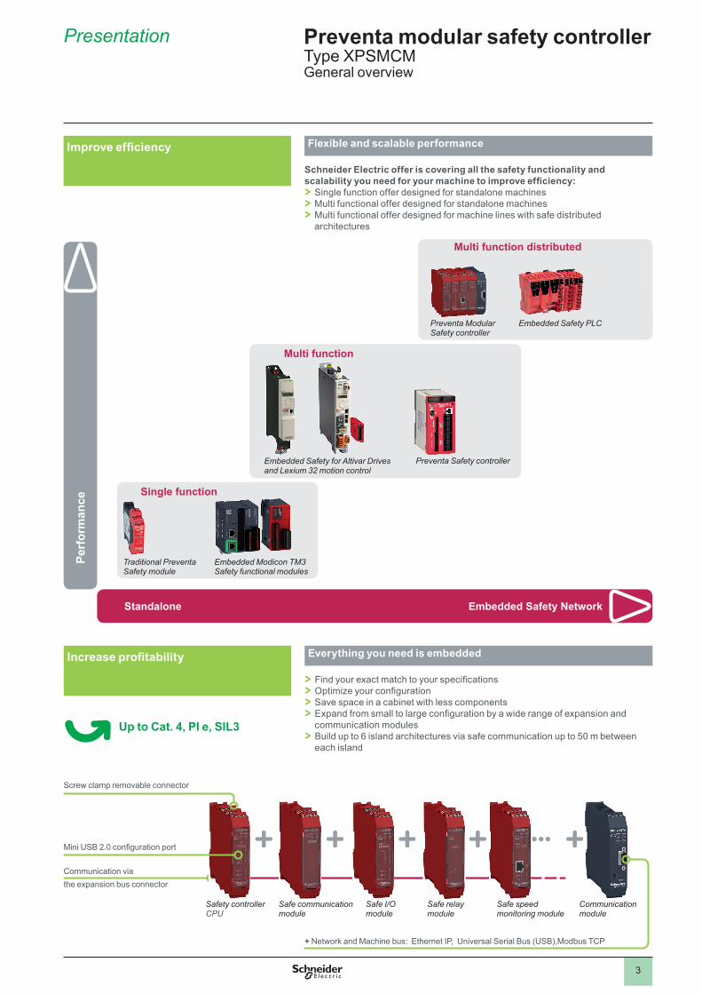
Improve efficiency Flexible and scalable performance
Schneider Electric offer is covering all the safety functionality and scalability you need for your machine to improve efficiency: > Single function offer designed for standalone machines > Multi functional offer designed for standalone machines > Multi functional offer designed for machine lines with safe distributed architectures
Perf
orm
ance
Embedded Safety NetworkStandalone
Embedded Modicon TM3 Safety functional modules
Single function
Traditional Preventa Safety module
Multi function distributed
Preventa Modular Safety controller
Embedded Safety PLC
Embedded Safety for Altivar Drives and Lexium 32 motion control
Multi function
Preventa Safety controller
Safe I/O module
Safe relay module
Safe communication module
Communication module
Communication via the expansion bus connector
Mini USB 2.0 configuration port
Safety controller CPU
+ Network and Machine bus: Ethernet IP, Universal Serial Bus (USB),Modbus TCP
Screw clamp removable connector
Increase profitability Everything you need is embedded
> Find your exact match to your specifications > Optimize your configuration > Save space in a cabinet with less components > Expand from small to large configuration by a wide range of expansion and communication modules > Build up to 6 island architectures via safe communication up to 50 m between each island
Up to Cat. 4, Pl e, SIL3
Safe speed monitoring module
2
1
3
4
5
6
7
8
9
10
2
1
3
4
5
6
7
8
9
10

4
Presentation Preventa modular safety controllerType XPSMCMGeneral overview
Reduce your time to market Intuitive automation with SoSafe Configurable
Easy configuration using intuitive software SoSafe Configurable
Configuration1 Define hardware
module configuration2 Creation project
configuration by drag and drop of function blocks and assignment of inputs and outputs
Online simulation & testing > Validate software configuration > View configuration behavior by on line simulation in graphic or text views.
Commissioning > Use project documentation to support the wiring and safety calculation to complete the commissioning.
Simplify integration & maintenance Connected everywhere
> Variety of communication bus for diagnostics for automation systems (I/O status, alarm and alert information) > Live diagnostics with PC via USB connection > Removable memory card transfering configuration data to new controller without using a PC
Customization and services
Our experts help you every step of the way, from perfecting machine design to on-site services of the finished machine. Global support, 24/7 hotline services, and replacement parts centers around the world enable you to deliver superior customer support and satisfaction.
2
1
3
4
5
6
7
8
9
10
2
1
3
4
5
6
7
8
9
10

5
Presentation Preventa modular safety controllerType XPSMCMGeneral overview
Make the most of your energySM
Schneider Electric - the provider of the complete safety chain powered by Preventa technology helping you simply to reach the right level of safety for your machine!
Approved
> Safety chain solutions to achieve the safety level required
2
1
3
4
5
6
7
8
9
10
2
1
3
4
5
6
7
8
9
10
6
Presentation Preventa modular safety controllerType XPSMCMSystem components
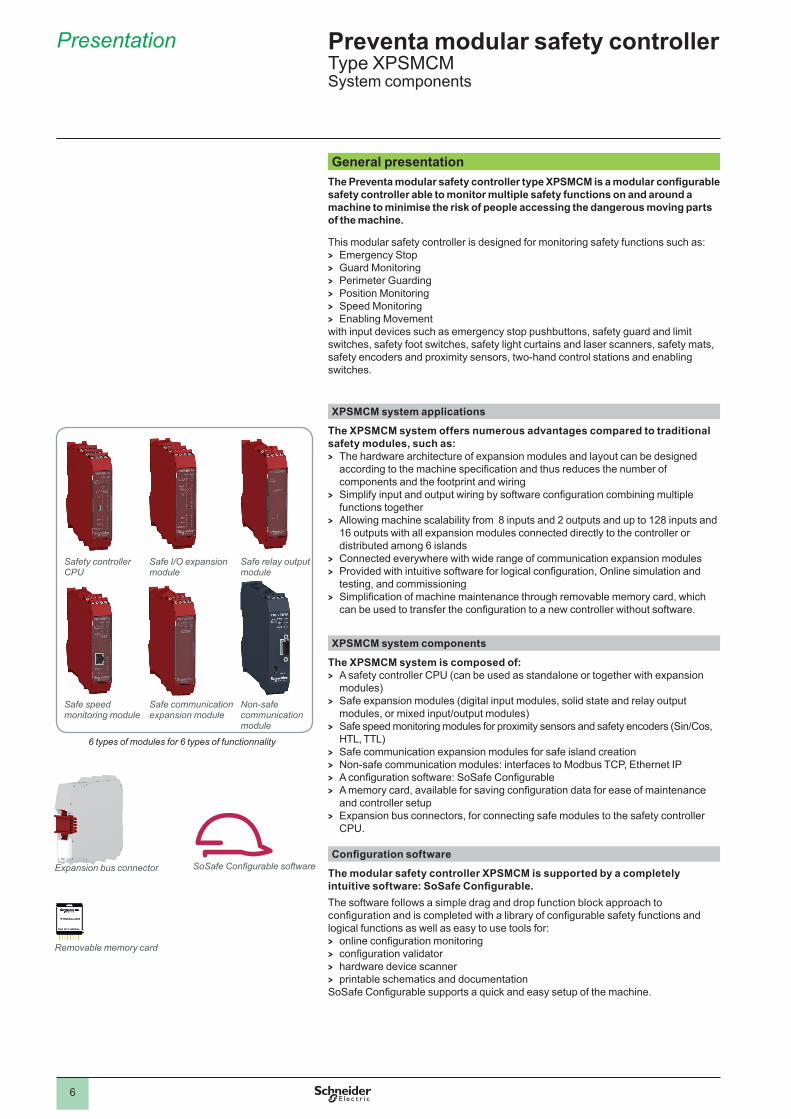
General presentationThe Preventa modular safety controller type XPSMCM is a modular configurable safety controller able to monitor multiple safety functions on and around a machine to minimise the risk of people accessing the dangerous moving parts of the machine.
This modular safety controller is designed for monitoring safety functions such as: > Emergency Stop > Guard Monitoring > Perimeter Guarding > Position Monitoring > Speed Monitoring > Enabling Movement
with input devices such as emergency stop pushbuttons, safety guard and limit switches, safety foot switches, safety light curtains and laser scanners, safety mats, safety encoders and proximity sensors, two-hand control stations and enabling switches.
XPSMCM system applications
The XPSMCM system offers numerous advantages compared to traditional safety modules, such as: > The hardware architecture of expansion modules and layout can be designed
according to the machine specification and thus reduces the number of components and the footprint and wiring
> Simplify input and output wiring by software configuration combining multiple functions together
> Allowing machine scalability from 8 inputs and 2 outputs and up to 128 inputs and 16 outputs with all expansion modules connected directly to the controller or distributed among 6 islands
> Connected everywhere with wide range of communication expansion modules > Provided with intuitive software for logical configuration, Online simulation and
testing, and commissioning > Simplification of machine maintenance through removable memory card, which
can be used to transfer the configuration to a new controller without software.
XPSMCM system components
The XPSMCM system is composed of: > A safety controller CPU (can be used as standalone or together with expansion
modules) > Safe expansion modules (digital input modules, solid state and relay output
modules, or mixed input/output modules) > Safe speed monitoring modules for proximity sensors and safety encoders (Sin/Cos,
HTL, TTL) > Safe communication expansion modules for safe island creation > Non-safe communication modules: interfaces to Modbus TCP, Ethernet IP > A configuration software: SoSafe Configurable > A memory card, available for saving configuration data for ease of maintenance
and controller setup > Expansion bus connectors, for connecting safe modules to the safety controller
CPU.
Configuration software
The modular safety controller XPSMCM is supported by a completely intuitive software: SoSafe Configurable. The software follows a simple drag and drop function block approach to configuration and is completed with a library of configurable safety functions and logical functions as well as easy to use tools for: > online configuration monitoring > configuration validator > hardware device scanner > printable schematics and documentation
SoSafe Configurable supports a quick and easy setup of the machine.
Expansion bus connector SoSafe Configurable software
Removable memory card
Safety controller CPU
Safe I/O expansion module
Safe communication expansion module
Non-safe communication module
6 types of modules for 6 types of functionnality
Safe relay output module
Safe speed monitoring module
2
1
3
4
5
6
7
8
9
10
2
1
3
4
5
6
7
8
9
10

7
Presentation Preventa modular safety controllerType XPSMCMCertification - Directive and standards
General presentationXPSMCM system certification
The XPSMCM system is certified by TüV SÜD meeting the industrial safety standards of Category 4, PL e according to EN/ISO 13849-1 and SILCL 3 according to IEC/EN 61508 and IEC/EN 60261.
Directive and standardsPreventa modular safety controller type XPSMCM complies with the following directives and standards.
Directives and standards Subject
2006/42/EC Machinery Directive
2004/108/EC Electromagnetic Compatibility (EMC)
2006/95/EC Low Voltage Directive (LVD)
IEC/EN 61131-2 Programmable Controllers, part 2: Equipment requirements and tests
EN/ISO 13849-1 Safety of machinery: Safety-related parts of control systems – Part 1: General principles for design
EN/ISO 13849-2 Safety of machinery: Safety-related parts of control systems – Part 2: Validation
EN 61496-1 (Type 4) Safety of machinery: Electro-Sensitive Protection Equipment, Part 1: General requirements and tests
IEC/EN 62061 Safety of machinery - Functional safety of safety-related electrical, electronic and programmable electronic control systems
EN 61508-1 Functional safety of electrical, electronic and programmable electronic safety-related systems – Part 1: General requirements
EN 61508-2 Functional safety of electrical, electronic and programmable electronic safety-related systems – Part 2: Requirements for electrical, electronic and programmable electronic safety-related systems
EN 61508-3 Functional safety of electrical, electronic and programmable electronic safety-related systems – Part 3: Software requirements
IEC 61784-3 Industrial communication networks - Profiles - Part 3: Functional safety field buses - General rules and profile definitions
e for Europe, cULus mark for USA and Canada
2
1
3
4
5
6
7
8
9
10
2
1
3
4
5
6
7
8
9
10

8
Presentation Preventa modular safety controllerType XPSMCMSystem components
Flexibility and scalabilityThe modular safety controller type XPSMCM provides flexibility and scalability starting with the main unit: the safety controller XPSMCMCP0802 > it embeds 8 safety digital inputs, 2 OSSD pairs and 2 status outputs,
It is an appropriate solution for machines with a small number of safety functions requiring the configuration flexibility of a safety controller. > The safety controller XPSMCMCP0802 can be used:
- as standalone - and also with 14 expansion modules: the system is expandable up to 128
inputs and 16 outputs, ideal for machines requiring multiple safety function monitoring
- Distributed architecture possible to connect via the safe bus expansion 6 islands up to 50 meters (164.04 ft.) apart.
Expansion of XPSMCM system
> Minimum size of hardware: a safety controller XPSMCMCP0802 is used as standalone.
8 safety digital inputs + 2 OSSD pairs + 2 status outputs
> Maximum size of hardware: a safety controller XPSMCMCP0802 connected to 14 expansion modules via the expansion bus connectors.
128 inputs and 16 OSSD pairs + 16 status outputs
Key figures of XPSMCM system
Each of the XPSMCM system components are compact designed: a single module dimensions are 22.5 x 99 x 114.5 mm, size of a typical safety relay.The safe components are red colored and equipped with: 1 Removable screw-type terminal blocks for connecting the safety channels and/or
the power supply2 slot for a memory card (only on safety controller)3 5 symmetrical rail locking clip4 slot for expansion bus connectors5 LEDs displaying the status (I/O, communication, power supply, reset, ...) 6 a protective cover7 mini USB 2.0 connector for configuration (only on safety controller)The non-safe components are black colored and equipped with:8 Removable screw-type terminal blocks for connecting the machine bus or
networks channels and/or the power supply9 5 symmetrical rail locking clip10 LEDs displaying the status (I/O, communication, power supply, reset, ...) 11 A specific connector for connecting to the machine bus or network (depending on
model) (see page 10)12 mini USB 2.0 connector for configuration
Non safe components(non-safe communication modules)
8
8
12
10
119
4
Expansion bus connectors
1
1
2
43
Safe components
5
67
2
1
3
4
5
6
7
8
9
10
2
1
3
4
5
6
7
8
9
10

9
Presentation Preventa modular safety controllerType XPSMCMSystem components
Flexibility and scalabilitySafe communication with decentralized I/O’s
The safety controller CPU has the possibility to create up to 6 decentralized safety related islands with a distance of 50 meters (164.04 ft.) between each island on a single Safety controller CPU.
> The safety controller CPU, the expansion modules and the safe communication expansion modules communicate safely through the use of the expansion bus connectors bus which are physically located on the back of each safe module.
> In order to create safe decentralized islands (cabinets), safe communication expansion modules are used ; they are connected in a line or tree configuration.
> The islands can be expanded to 50 meters (164.04 ft.) between islands and use RS 485 cabling.
> The order of the safe expansion modules connected with the expansion bus connectors is not important, the configuration automatically recognises the architecture based on the module addressing.
Ethernet
RS 485 Up to 6 decentralized islands
1 2 43
2 3 2 23 3
Decentralized cabinet 1 Decentralized cabinet 2 Decentralized cabinet 3
5 67
Safe expansion modules
Safe expansion module Safe expansion modules
Safe expansion modules
Safety related communication RS 485 serial interface shielded cable (up to 50 m /164.04 ft.) between 2
decentralized islands)1 Safety controller CPU2 Safe communication expansion modules (line configuration) 3 Safe expansion modules: mixed I/O modules, Safe relay output modules, Safe
speed monitoring modules for proximity sensors and safety encodersNon-safety related communication4 Non-safe communication modules: interfaces to Ethernet IP, ModbusTCP, for
non-safety related communication5 Modicon TM4 communication module (Ethernet switch module)6 Modicon M241 logic controller7 Modicon TM3 expansion I/O module
2
1
3
4
5
6
7
8
9
10
2
1
3
4
5
6
7
8
9
10

10
Presentation Preventa modular safety controllerType XPSMCMSafety controller, expansion modules
XPSMCM system componentsSafety controller
The safety controller XPSMCMCP0802 is designed to monitor a safety configuration. Its configuration is created using the software SoSafe Configurable.
The safety controller CPU is also usable as a standalone device or able to be connected to any of the expansion units of the XPSMCM system such as I/O expansion modules, relay output modules, communication expansion modules, speed monitoring modules and non-safe fieldbus communication modules.The safety controller features: > A configuration memory card (optional) > A LOG file containing the last 5 configuration modifications in chronological order,
with date of modification > 24 terminals in 22.5 mm (0,89 in.) > Connection with other expansion modules via the expansion bus connectors (sold
separately) > mini USB 2.0 connector for configurationSafety controller reference
Description
XPSMCMCP0802 > 8 safety digital inputs > 2 OSSD pairs with 400 mA output current > 4 test outputs for line control monitoring of input circuits > 2 inputs for Start/Restart interlock and external device monitoring
(EDM) > 2 configurable status outputs
Expansion modules
6 types of expansion modules are available, designed for safety inputs or outputs.The safety inputs/outputs are configurable individually or in pairs, with several possibilities: > Monitoring using line control monitoring via dedicated test outputs > Configurable filters and delays for each single input > Configurable output activation and de-activation delays > Independent control of pairs of outputs > Configurable diagnostic output signals > Simple diagnostics via front led signalling, configuration software, communication
expansion modules
Expansion module reference (item)
Description
XPSMCMMX0802 (1) > 8 digital inputs > 2 OSSD pairs with 400mA output current > 4 test outputs for line control monitoring of input circuits > 2 configurable status outputs > 2 inputs for Start/Restart interlock and external device monitoring
(EDM)
XPSMCMDI0800 (2) > 8 digital inputs > 4 test outputs for line control monitoring of input circuits
XPSMCMDI1600 (3) > 16 digital inputs > 4 test outputs for line control monitoring of input circuits
XPSMCMDI1200MT (4) > 12 digital inputs > 8 test outputs for line control monitoring: can monitor up to four
4-wire safety mats
XPSMCMDO0002 (5) > 2 OSSD pairs with 400mA output current > 2 inputs for Start/Restart interlock and external device
monitoring (EDM) > 2 configurable status outputs
XPSMCMDO0004 (6) > 4 OSSD pairs with 400mA output current > 4 inputs for Start/Restart interlock and external device
monitoring (EDM) > 4 configurable status outputs
> The Safe expansion modules are connected to the safety controller CPU via the expansion bus connectors.
Safety controller CPU
mini USB 2.0 connector for configuration
Safe expansion modules
1
5
2 3
4 6
2
1
3
4
5
6
7
8
9
10
2
1
3
4
5
6
7
8
9
10

11
Presentation Preventa modular safety controllerType XPSMCMSafe relay output modules, Safe speed monitoring modules
XPSMCM system componentsSafe relay output modules
4 types of safe relay output modules are available. Safe relay output module reference (item)
Description
XPSMCMER0002 (1) > 2 forcibly guided contact safety relay output (2 NO + 1 NC) modules without backplane connection not connected to the backplane bus.
> 1 inputs for Start/Restart interlock and external device monitoring (EDM)
XPSMCMER0004 (2) > 4 forcibly guided contact safety relay output (2 NO + 1 NC) modules without backplane connection not connected to the backplane bus
> 2 inputs for Start/Restart interlock and external device monitoring (EDM)
> The safe relay output modules XPSMCMER000p do not require the expansion bus connectors as they are directly wired to the selected OSSDs.
XPSMCMRO0004 (3) > 4 forcibly guided contact safety relay output modules with backplane connection
> Expansion module with 4 independent safety relay outputs and the corresponding 4 inputs for the external feedback contacts (EDM)
> The relay can be configured according to Category 1, 2 and 4 architectures
XPSMCMRO0004DA (4) > 4 forcibly guided contact safety relay output modules with backplane connection
> Expansion module with 4 independent safety relay outputs and the corresponding 4 inputs for the external feedback contacts (EDM)
> The relay can be configured according to Category 1, 2 and 4 architectures
> 8 configurable status outputs
> The safe relay output modules XPSMCMRO000p are connected to the safety controller CPU via the expansion bus connectors.
Safe speed monitoring modules
The safe speed monitoring modules are designed to monitor zero speed control, max speed (limited speed), speed range and direction. > Up to 4 logically selectable limited speed thresholds (freely configurable via
SoSafe Configurable software) for each logical intput (axis) > The safe speed monitoring modules (excluding XPSMCMEN0200) are equipped
with RJ 45 connectors (1 or 2 depending on the model) for encoders and terminal blocks for proximity switches
> Max input frequency: 500 kHz for encoder monitoring and 5 kHz for proximity sensors
> The modules can be configured with incremental encoders and PNP/NPN proximity switches as described below:
Safe speed monitoring module reference (item)
Description Connector type
XPSMCMEN0100SC (1) > 1 input for Sin/Cos encoder + 1 or 2 proximity switches
1x RJ 45 (ENC1) and terminal blocks for proximity sensor wiring
XPSMCMEN0200SC (2) > 1 or 2 inputs for Sin/Cos encoders + 1 or 2 proximity switches
2x RJ 45 (ENC1/ENC2) and terminal blocks for proximity sensor wiring
XPSMCMEN0200 (3) > 2 inputs for proximity switches Terminal blocks for proximity sensor wiring
> The safe speed monitoring modules are connected to the safety controller CPU via the expansion bus connectors.
Safe relay output modules
1 2 3 4
Safe speed monitoring modules
2 31
2
1
3
4
5
6
7
8
9
10
2
1
3
4
5
6
7
8
9
10

12
Presentation Preventa modular safety controllerType XPSMCMSafe communication expansion modules, Non-safe communication modules
XPSMCM system componentsSafe communication expansion modules
The safe communication expansion modules enable the connection of XPSMCMCP0802 Modular Safety Controller with expansion modules placed at distances, 50 m ( 164 ft). Using RS 485 shielded cable two XPSMCMCO0000S modules placed at the desired distance can be linked together thus joining the expansion modules to the Modular Safety Controller. > Each XPSMCMCO0000S2 safe communication expansion module has two
independent connection channels; the connection of two XPSMCMCO0000S2 can be performed by wiring a channel of your choice.
> The XPSMCMCO0000S1 safe communication expansion module has only one channel and must be connected as the first or last module.
> Up to 6 islands can be created using the safe communication modules with a total length of 250 meters (820.2 ft) and a maximum of 50 meters (164 ft) between two safe communication modules. The system response time does not change with the use of the safety communication modules.
Safe communication expansion module reference (item)
Description
XPSMCMCO0000S1 (1) > 1 connection interface: 1 input or 1 output (1) network connection
XPSMCMCO0000S2 (2) > 2 connections interface: 1 input and 1 output network connection
(1) End of the network or Start of the network if connected to a single RS 485 cable
Non-safe fieldbus communication modules
The non-safe communication modules are designed for diagnostics connection and data communication purposes to machine field bus or network systems. non-safe fieldbus communication module reference (item)
Machine bus/network interface Connector type
XPSMCMCO0000EI (1) > Ethernet IP 1x RJ 45 (in/out)
XPSMCMCO0000UB (2) > Universal Serial Bus Mini USB
XPSMCMCO0000EM (3) > Modbus TCP 1x RJ 45 (in/out)
> The non-safe communication modules are connected to the safety controller via the Expansion bus connector. Each of them have a mini USB 2.0 connector for configuration
> Only one non-safe communication module type can be connected on a safety controller.
Non-safe communication modules
2 31
Safe communication expansion modules
1 22
1
3
4
5
6
7
8
9
10
2
1
3
4
5
6
7
8
9
10

13
Presentation Preventa modular safety controllerType XPSMCMAccessories, software
Memory card
Expansion bus connector
XPSMCM system componentsAccessories
b Memory card
XPSMCMMEM0000 is a removable memory card that can be used to save XPSMCM configuration data for subsequent transfer to a new device without using a PC. > The configuration in the XPSMCMMEM0000 overwrites any other configuration
present on the safety controller CPU XPSMCMCP0802, replacing this with that contained in the card.
> This configuration replacement function can be disabled on the safety controller CPU via SoSafe Configurable software.
> Overwrite operations are recorded in chronological order in the safety controller CPU XPSMCMCP0802 LOG file.
b Expansion bus connector
XPSMCMCN0000SG is an expansion bus connector: > It provides a safe communication between safe expansion components and the
safety controller CPU, > Only the XPSMCMCP0802 safety controller CPU requires the purchase of the
expansion bus connector. The expansion modules are provided with one expansion bus connector.
b Configuration cable
TCSXCNAMUM3P is a configuration cable to be used for software configuration between a PC and the safety controller CPU. > Length 3 m > It is equipped with USB connectors: USB A and USB mini B
b Safe communication cable
> RS 485 serial interface shielded cable are used between the safe communications expansion modules to create up to 6 decentralized safety related islands
> Available lengths: 10 to 50 m (32.81 to 164.04 ft)
b Encoder splitter cable
> The encoder splitter cable enables the connection of an embedded encoder within the PacDrive M motion system to the speed monitoring module of the modular safety controller
> Available lengths: 1 to 5 m (3.3 to 16.4 ft)
Software
The SoSafe Configurable software, installed on a PC, is used to create complex logical conditions using logical operators and safety functions, such as muting, timer, counters, memories, etc. via a simple and intuitive graphic configuration interface. Configuration data are transferred to the safety controller CPU XPSMCMCP0802 via a USB link.
SoSafe Configurable software
2
1
3
4
5
6
7
8
9
10
2
1
3
4
5
6
7
8
9
10

14
References Preventa modular safety controllerType XPSMCMSystem components
Safety controllerDescription Inputs
(number & type)
Outputs(number & type)
Connector type
Reference Weightkg/lb
Safety controller CPU
8 digital inputs + 2 for Start/Restart interlock
2 OSSD pairs + 4 test outputs + 2 status outputs
Screw XPSMCMCP0802 0.250/0.55
Safe expansion modulesSafe expansion modulesDescription Inputs
(number & type)
Outputs(number & type)
Connector type
Reference Weightkg/lb
Safe mixed I/O expansion modules
8 digital inputs+ 2 for Start/Restart interlock
2 OSSD pairs + 4 test outputs + 2 status outputs
Screw XPSMCMMX0802 0.250/0.55
Safe input expansion modules
8 digital inputs
4 test outputs Screw XPSMCMDI0800 0.230/0.51
16 digital inputs
4 test outputs Screw XPSMCMDI1600 0.250/0.55
12 digital inputs
8 test ouputs for 4 wires safety Mats
Screw XPSMCMDI1200MT 0.250/0.55
Safe output expansion modules
2 for Start/Restart interlock
2 OSSD pairs + 2 status outputs
Screw XPSMCMDO0002 0.230/0.51
4 for Start/Restart interlock
4 OSSD pairs + 4 status outputs
Screw XPSMCMDO0004 0.250/0.55
Safe relay output modulesSafe relay output modules (without backplane expansion connection)
1 for Start/Restart interlock
2 relays(2 NO +1 NC)
Screw XPSMCMER0002 0.250/0.55
2 for Start/Restart interlock
4 relays (4 NO + 2 NC)
Screw XPSMCMER0004 0.300/0.66
Safe relay output modules (Wiring with the expansion bus connector)
4 for Start/Restart interlock
4 relays
Screw XPSMCMRO0004 0.300/0.66
4 for Start/Restart interlock
4 relays with 8 status outputs
Screw XPSMCMRO0004DA 0.330/0.73
Safe speed monitoring modulesDescription b Inputs (number & type)
b Connector typeConnector type
Reference Weightkg/lb
Safe speed monitoring modules
v 1 Sin/Cos encoder and 2 proximity sensor inputs
v 1x RJ 45 (ENC1) v Proximity sensor
connection via terminal blocks
Screw XPSMCMEN0100SC 0.280/0.62
v Up to 2 Sin/Cos encoders and 2 proximity sensor inputs
v 2x RJ 45 (ENC1/ENC2) v Proximity sensor
connection via terminal blocks
Screw XPSMCMEN0200SC 0.300/0.66
v 2 inputs for proximity switches
v Proximity sensor connection via terminal blocks
Screw XPSMCMEN0200 0.230/0.51
XPSMCMCP0802
XPSMCMMX0802
XPSMCMDO0002
XPSMCMDI0800 XPSMCMDI1600
XPSMCMDI1200MT XPSMCMDO0004
XPSMCMEN0100SC XPSMCMEN0200SC XPSMCMEN0200
XPSMCMER0002
XPSMCMRO0004
XPSMCMER0004
XPSMCMRO0004DA
2
1
3
4
5
6
7
8
9
10
2
1
3
4
5
6
7
8
9
10

15
References (continued) Preventa modular safety controllerType XPSMCMSystem components
Safe expansion modules (continued)Safe communication expansion modulesDescription Characteristics Connector
typeReference Weight
kg/lbSafe RS 485 bus expansion module for remote extension
1 connection interface: 1 input or 1 output network connection
Screw XPSMCMCO0000S1 0.300/0.66
2 connections interface: 1 input and 1 output network connection
Screw XPSMCMCO0000S2 0.300/0.66
Non-safe fieldbus communication modulesDescription b Field bus / network type
b ConnectorConnector type
Reference Weightkg/lb
Non-safe communication modules
v Ethernet IP v 1x RJ 45 (in/out)
Screw XPSMCMCO0000EI 0.300/0.66
v Universal Serial Bus (Mini USB)
Screw XPSMCMCO0000UB 0.300/0.66
v Modbus TCP v 1x RJ 45 (in/out)
Screw XPSMCMCO0000EM 0.300/0.66
AccessoriesDescription Application Reference Weight
kg/lbMemory card For saving configuration data for
subsequent transfer to a new device without using a PC
XPSMCMME0000 0.004/0.009
Configuration cable
v Configuration cable to be used for software configuration between a PC and the safety controller CPU
v Equipped with 2x USB connectors: USB A and USB mini B
3 m /9.84 ft
TCSXCNAMUM3P 0.065/0.143
RS 485 shielded cable
For use between two safe communication expansion modules
10 m / 32.81 ft
TSXSCMCN010 0.920/2.03
25 m / 82.02 ft
TSXSCMCN025 2.300/5.07
50 m /164.04 ft
TSXSCMCN050 4.600/10.14
Encoder splitter cable
For use between safe speed monitoring modules and PacDrive M
1 m / 3.3 ft
TSXESPPM001 0.110/0.24
3 m / 9.84 ft
TSXESPPM003 0.310/0.68
5 m /16.40 ft
TSXESPPM005 0.510/1.12
Expansion bus connector (1)
For connecting the various expansion modules to the safety controller CPU
XPSMCMCN0000SG 0.001/0.002
(1) This reference only needs to be ordered for the XPSMCMCP0802 reference when it is connected to expansion modules.
XPSMCMCO0000S1 XPSMCMCO0000S2
XPSMCMCO0000EI XPSMCMCO0000UB XPSMCMCO0000EM
XPSMCMCN0000SG
XPSMCMME0000
TCSXCNAMUM3P
2
1
3
4
5
6
7
8
9
10
2
1
3
4
5
6
7
8
9
10

16
Presentation Preventa modular safety controllerType XPSMCM Configuration software: SoSafe Configurable
Text visualization
Graphic visualization
The I/O MONITOR allows the real-time monitoring of all the I/O of a Preventa XPSMCM system and the diagnostic information about a working system.
Configuration software: SoSafe ConfigurableSoSafe Configurable is used to create complex logical conditions using logical operators and safety functions, such as muting, timer, counters, memories, etc. via a simple and intuitive graphic configuration interface. Configuration data are transferred to the safety controller XPSMCMCP0802 via a USB link. > XPSMCMCP0802 safety controller has a mini USB 2.0 connection to connect to a
PC where the SoSafe Configurable software is installed. > An application held on XPSMCMCP0802 safety controller can be saved on the
memory card (optional) for fast transfer of the configuration data to other modules. PasswordThe SoSafe Configurable software is protected with 2 levels of alphanumerical password (max 8 characters.) > The level 1 password is an operation and maintenance password. It allows only to
view the LOG file, the composition of the system and use the real time MONITOR . > The level 2 password enables all features of the software to be accessible.
Allowing to load, modify, save, and download (from the PC to XPSMCMCP0802 safety controller) a project configuration.
LOG file (Level 1 password).A log file with the creation date and CRC checksum (4-digit hexadecimal identification) of a project are stored in the safety controller CPU. > A logbook can record up to 5 consecutive events, after which these are
overwritten, starting from the least recent event. > The log file can be visualized using the icon in the standard tool bar.
Main features
SoSafe Configurable software main features are: > “Drag & Drop” configuration of all safety functions and logic > Functional validation of design > 2-level password management for the prevention of unauthorised access and
therefore of incidental modifications or tampering with system configuration > Configuration of parameters of function blocks, for example:
- single - or double - channel NO or NC inputs - test outputs for monitoring of electro-mechanical input devices and photocells
and related electrical connections - automatic, manual and monitored manual restart - synchronisation control of two channels - contact anti-rebound filters and timers - start-up test.
> Single or bi-directional 2 or 4 sensor muting function blocks > Online monitoring of I/O status > Project documentation and schematics
System requirements
SoSafe Configurable software runs on PC with: > RAM: 256 MB > Hard disk: free space > 300 MB > USB connector: 1.1 or 2.0 > Microsoft Windows® XP SP3 (service Pack 3) / Vista 32-bit, Microsoft Windows® 7
32 and 64-bit , Microsoft Windows® 8.1 32 and 64-bit > Microsoft Framework 3.5 (or higher).
SoSafe Configurable software
Safety controller CPU
Mini USB 2.0 connector for configuration
TCS
XC
NA
MU
M3P
2
1
3
4
5
6
7
8
9
10
2
1
3
4
5
6
7
8
9
10

17
Presentation, references
Preventa modular safety controllerType XPSMCMConfiguration software: SoSafe Configurable
Safety level parameters
Parameter Value Standard
PFHd u 10-8 PFHd < 10-7 IEC 61508SIL 3SILCL 3 IEC 62061Type 4 EN 61496-1PL e ISO 13849-1, IEC 62061DCavg HighMTTFd (years) 100 yearsCategory 4Operation life time 20 years
Configuration software for XPSMCM systemDescription Characteristics Reference Weight
kg /lb
SoSafe Configurable v Version 1.0 v Download from Schneider website v User manual included v Available languages: English,
French, Italian, German, Spanish, Chinese and Japanese
v Microsoft Windows® XP SP3 / Vista, Microsoft Windows® 7, Microsoft Windows® 8.1
v Minimum PC requirement: 256 MB RAM, 300 MB mini. free space on Hard drive
v mini USB connector 1.1 or 2.0
XPSMCMSW0000V10 0.520/1.15
XPSMCMSW0000V10
2
1
3
4
5
6
7
8
9
10
2
1
3
4
5
6
7
8
9
10

18
Presentation Preventa modular safety controllerType XPSMCMSoSafe Configurable software: operator function blocks
Function blocksInput objects
E-STOP Verifies an emergency stop device inputs status. If the emergency stop button has been pressed (contacts open) the output is 0. If not the output is 1.
SAFETY GUARD Verifies a mobile guard or safety gate device input status. If the mobile guard or safety gate is open, the output is 0. Otherwise the output is 1.
ENABLE (enable key) Verifies a manual key device Input status. If the key is not turned the output is 0. Otherwise the output is 1.
LIGHT CURTAIN (optoelectronic safety light curtain / laser scanner)
Verifies an optoelectronic safety light curtain (or laser scanner) inputs state. If the area protected by the light curtain is occupied, (light curtain outputs LOW) the output is 0. Otherwise, with the area clear and outputs to 1 the output of this function block is 1.
FOOTSWITCH (safety pedal)
Verifies the status of the inputs of a safety pedal device. If the pedal is not pressed the output is 0. Otherwise the output is 1.
PHOTOCELL (safety photocell)
Verifies the status of the inputs of an optoelectronic safety photocell. If the beam of the photocell is occupied (photocell output FALSE) the output is 0. Otherwise with the beam clear and an output of 1 the output is 1.
SELECTOR SWITCH Verifies the status of the inputs from a mode selector (up to 4 inputs). If only one input is 1 the corresponding output is also 1. In all other cases, and thus when all inputs are 0 or more than one input is 1 all the outputs are 0.
TWO HAND CONTROL Verifies the status of the inputs of a two hand control switch. Only if both the press-buttons are pressed within 500 msec the output is 1. Otherwise the output is 0.
SAFETY MAT (safety mat or safety edge)
Verifies the status of the inputs of a safety mat. If a person stands on the mat the output is 0. Otherwise, with the mat clear, the output is 1. Test outputs must be used. Can’t be used with 2-wire mats and termination resistance mats.
ENABLE SWITCH Checks the input Inx status of an Enabling Switch. In the event that the switch is not pressed (position 1) or completely pressed (position 3), the OUTPUT will be 0 (FALSE). If it is pressed in the middle (position 2), the output will be 1 (TRUE).
TESTABLE SAFETY DEVICE
The function can be used with every generic input either one or two channels and either NO or NC contacts.
SENSOR Verifies the status of the input of a sensor (not a safety sensor). If the beam of the sensor is occupied (sensor output FALSE) the output is 0. Otherwise, with the beam clear and an output of 1 then the output is 1.
LOCK FEEDBACK Provides the feedback from the Guardlock solenoid generating a 1(TRUE) when the guardlock is locked and 0 (FALSE) when open.
SWITCH Verifies the input status of a pushbutton or switch (NOT SAFETY SWITCHES). If the pushbutton is pressed the output is 1. Otherwise, the output is 0.
SOLID STATE DEVICE Verifies INx input status. If the the inputs are High the output is 1 else 0.
FIELDBUS INPUT Provides the fieldbus input value signals (up to 8 bits) from the machine control unit via the field-bus module. The signal is connected directly into the diagrams without using any input block.
LL0 0 (FALSE) input value
LL1 1 (TRUE) input value
Speed MonitoringZero Speed Monitoring Verifies the speed of a device generating an output 1 (TRUE) when the speed is 0. If the speed is
different from 0 generates an output 0 (FALSE).
Zero and Max Speed Monitoring
Verifies the speed of a device generating an output Zero = 1 (TRUE) when the speed is 0. If the speed is different from 0 generates an output Zero = 0 (FALSE). Moreover, this block verifies the speed of a device generating an output Over = 0 (FALSE) when the speed is over a defined threshold.
Maximum Speed Monitoring
Verifies the speed of a device generating an output 0 (FALSE) when the speed is over a defined threshold.
Speed Range Monitoring Verifies the speed of a device generating an output 1 (TRUE) when the speed is inside a defined range.
Output objectsOSSD (safety outputs) The OSSD semiconductor PNP safety static output pair.
The 2 output cannot operate independently. Each OSSD pair can work in both AUTO/Manual restart mode and can perform the EDM of external relays using the dedicated RESTART_FBK input. Each OSSD pair can be set for giving the actual output status information.
STATUS (signal output) It is possible to monitor any point on the schematic by connecting it to the input of this block. The output returns 24VDC if the input is 1, or 0Vdc if the input is 0. (STATUS is not a safety output)It is possible to connect the Status to the OSSD status signal to have a signal output of the REAL OSSD output status, including the restart signal effect.
Relay Gives a closed the contact when In is 1 (TRUE); otherwise an open contact when In is 0 (FALSE). Configurable to Category 1, 2 and 4.
FIELDBUS PROBE OUTPUT
Provides the fieldbus input value signals (up to 16 bits) to the machine control unit via the field-bus module. The signal is connected directly into the diagrams without using any output block.
2
1
3
4
5
6
7
8
9
10
2
1
3
4
5
6
7
8
9
10

19
Presentation Preventa modular safety controllerType XPSMCMSoSafe Configurable software: operator function blocks
Function blocksMuting operators
MUTING “L” with 2 Muting sensors, only for one-way openings
Performs muting of the input signal through sensor inputs S1 and S2.Muting closes when the input signal rises.
MUTING “T” with 2 Muting sensors for two-way openings
Performs muting of the input signal through sensor inputs S1 and S2.
MUTING “Sequential” with 4 Muting sensors for two-way openings
Performs muting of the input signal through sensor inputs S1, S2, S3 and S4.
MUTING “Concurrent” with 4 Muting sensors for two-way openings
Performs muting of the input signal through sensor inputs S1, S2, S3 and S4.
MUTING OVERRIDE Is necessary when the machine stops with the material still in the guaerde gate, due to some wrong muting sequence.OVERRIDE command forces the output high allowing to remove the material obstructing the gate.Two different way of operation are available:1 Manual action with hold to run,2 Automatic with pulse command.
General/MiscellaneousSerial Output Transfers the state of up to a maximum of 8 inputs into a serial line data output.
Network Allows to distribute in a local network Stop and Reset commands.
Interpage IN and Interpage OUT
Memory bit which are reused from inputs to multiple outputs.
Memory operatorsD FLIP FLOP Saves the previously set status on output Q on the clock rising edge.
SR FLIP FLOP Brings output Q at 1 with Set, 0 with Reset.
USER RESTART MANUAL Makes it possible to memorize the Restart signal on a rising edge of the Res input.
USER RESTART MONITORED
Makes it possible to memorize the Restart signal on a rising edge followed by a falling edge of the Res input.
Counter operatorCOUNTER The operator COUNTER is a pulse counter.
The counter generates a pulse as soon as the set count is reached. There are 3 operationg modes:1 AUTOMATIC (default),2 MANUAL,3 AUTOMATIC + MANUAL.
Timer operatorsPULSE GENERATOR Generates a clock signal output with the desired period if the input In is 1.
MONOSTABLE Generates a level 1 output activated by the rising edge of the input and remains in this condition for the set time.
PASSING MAKE CONTACT
The output follows the signal on the input. However, if this is 1 for longer than the set time, the output changes to 0.
DELAY Applies a delay to a signal by setting the output to 1 after the set time, against a change in the level of the input signal.
Logical operatorsAND Returns 1 as output if all the inputs are 1
NAND Returns 0 as output if all the inputs are 1.
NOT Inverts the logical status of the input.
OR Returns 1 as output if at least one of the inputs is 1.
NOR Returns 0 as output if at least one of the inputs is 1.
XOR Returns 0 as output if all the inputs are in the same logical status.
XNOR Returns 1 as output if all the inputs are in the same logical status.
MULTIPLEXER Forwards the signal of the inputs to the output according to the Sel selection.
2
1
3
4
5
6
7
8
9
10
2
1
3
4
5
6
7
8
9
10

20
TTCSXCNAMUM3P 15TSXESPPM001 15TSXESPPM003 15TSXESPPM005 15TSXSCMCN010 15TSXSCMCN025 15TSXSCMCN050 15
XXPSMCMCN0000SG 15XPSMCMCO0000EI 15XPSMCMCO0000EM 15XPSMCMCO0000S1 15XPSMCMCO0000S2 15XPSMCMCO0000UB 15XPSMCMCP0802 14XPSMCMDI0800 14XPSMCMDI1200MT 14XPSMCMDI1600 14XPSMCMDO0002 14XPSMCMDO0004 14XPSMCMEN0100SC 14XPSMCMEN0200 14XPSMCMEN0200SC 14XPSMCMER0002 14XPSMCMER0004 14XPSMCMME0000 15XPSMCMMX0802 14XPSMCMRO0004 14XPSMCMRO0004DA 14XPSMCMSW0000V10 17
Index Product reference index
2
1
3
4
5
6
7
8
9
10
2
1
3
4
5
6
7
8
9
10

2
1
3
4
5
6
7
8
9
10
2
1
3
4
5
6
7
8
9
10
The information provided in this documentation contains general descriptions and/or technical characteristics of the performance of the products contained herein. This documentation is not intended as a substitute for and is not to be used for determining suitability or reliability of these products for specific user applications. It is the duty of any such user or integrator to perform the appropriate and complete risk analysis, evaluation and testing of the products with respect to the relevant specific application or use thereof. Neither Schneider Electric nor any of its affiliates or subsidiaries shall be responsible or liable for misuse of the information contained herein.
Design: Schneider ElectricPhotos: Schneider Electric
Head Office35, rue Joseph MonierF-92500 Rueil-MalmaisonFrance
Schneider Electric Industries SAS
More information on http://www.schneider-electric.com/machinesafety
DIA
3ED
2140
901E
N
01/2015