prevention of coupled structure-propulsion (pogo)
TRANSCRIPT

NASA NASA SP-8055 SPACE VEHICLE DESIGN CRITERIA (STRUCTURES )
PREVENTION OF COUPLED
INSTABILITY (POGO) STRUCTURE-PROPULSION
OCTOBER 1970
NATIONAL AERONAUTICS AND SPACE ADMINISTRATION

4
NASA experience has indicated a need for uniform criteria for the design of space vehicles. Accordingly, criteria are being developed in the following areas of technology:
Environment Structures Guidance and Control Chemical Propulsion
Individual components of this work will be issued as separate monographs as soon as they are completed. A list of all previously issued monographs in this series can be found at the end of this document.
These monographs are t o be regarded as guides to design and not as NASA requirements, except as may be specified in formal project specifications. It is expected, however, that the criteria sections of these documents, revised as experience may indicate to be desirable, eventually will become uniform design requirements for NASA space vehicles.
This monograph was prepared under the cognizance of the Langley Research Center. The Task Manager was G. W. Jones, Jr. The author was S. Rubin of The Aerospace Corporation. A number of other individuals assisted in developing the material and reviewing the drafts. In particular, the significant contributions made by L. L. Bickford of Aerojet-General Corporation; F. E. Bikle, B. L. Bogema, and R. L. Goldman of Martin Marietta Corporation; T. Bullock of NASA George C. Marshall Space Flight Center; W. F. Davis and D. L. Keeton of McDonnell Douglas Corporation; J. R. Fenwick of North American Rockwell Corporation; L. D. Pinson of NASA Langley Research Center; R. L. Rich of The Boeing Company; R. G. Rose of General Dynamics Corporation; and J. H. Walker of TRW Systems Group/TRW Inc. are hereby acknowledged.
October 1970

For sale by the National Technical Information Service, Springfield, Virginia 22151 - Price $3.00

I
i
1 . INTRODUCTION . . . . . . . . . . . . . . . . . . . . . . 1
2 . STATEOFTHEART . . . . . . . . . . . . . . . . . . . . 6
2.1 Mathematical Models . . . . . . . . . . . . . . . . . . . 7 2.1.1 Structural Modeling . . . . . . . . . . . . . . . . 8 2.1.2 Propulsion-System Modeling . . . . . . . . . . . . . 9
2.2 Stability Analysis . . . . . . . . . . . . . . . . . . . -13 2.3 Corrective Devices or Modifications . . . . . . . . . . . . . 15 2.4 Flight Evaluation . . . . . . . . . . . . . . . . . . . . 18
3 . CRITERIA . . . . . . . . . . . . . . . . . . . . . . . . 19
3.1 Mathematical Models . . . . . . . . . . . . . . . . . . . 19 3.2 Preflight Tests . . . . . . . . . . . . . . . . . . . . . 19 3.3 Stability Analysis . . . . . . . . . . . . . . . . . . . . 19 3.4 Corrective Devices or Modifications . . . . . . . . . . . . . 20 3.5 Flight Evaluation . . . . . . . . . . . . . . . . . . . . 20
4 . RECOMMENDED PRACTICES . . . . . . . . . . . . . . . . . 20
4.1 Mathematical Models . . . . . . . . . . . . . . . . . . . 20 4.1 . 1 Structural Modeling . . . . . . . . . . . . . . . . 20 4.1.2 Propulsion-System Modeling . . . . . . . . . . . . . 22
4.2 Preflight Tests . . . . . . . . . . . . . . . . . . . . . 23 4.2.1 Structural Testing . . . . . . . . . . . . . . . . . 23
4.2.3 Special Propulsion Testing . . . . . . . . . . . . . . 25 4.3 Stability Analysis . . . . . . . . . . . . . . . . . . . . 26 4.4 Corrective Devices or Modifications . . . . . . . . . . . . -29 4.5 Flight Evaluation . . . . . . . . . . . . . . . . . . . -31
4.2.2 Normal Propulsion-Development Testing . . . . . . . . -24
APPENDIX Assessment of Significance of Structural Modes . . . . . . . . . . . . . . . . . 35
REFERENCES . . . . . . . . . . . . . . . . . . . . . . . 37
SYMBOLS -45 . . . . . . . . . . . . . . . . . . . . . . .
NASA SPACE VEHICLE DESIGN CRITERIA MONOGRAPHS ISSUED TO DATE . . . . . . . . . . . . . . . 47
... 111

PREVENTION OF COUPLED
I N STAB I LITY (POGO) STRUCTURE-PROPULSION
1. INTRODUCTION
Many liquid-propellant rocket vehicles have experienced longitudinal vibration because of an instability arising from interaction of the vehicle structure with the propulsion system. The vibrations, nicknamed “pogo” after the jumping stick, have occurred principally in the first longitudinal structural mode during operation of the first liquid-propellant stage of a launch vehicle. A generalized representation of the effects of a typical instability is illustrated in figure 1. The vibration begins spontaneously, intensifies, and then dies away - typically in a period of 10 t o 40 seconds. The frequency of vibration tracks that of the first structural mode, which increases as propellant decreases. Less often, pogo vibrations have occurred in higher modes of longitudinal vibration; also, multiple periods of instability, each involving a different mode of vibration, have occurred during operation of a single vehicle stage. Vibrations have occurred in the frequency range of 5 to 60 Hz, with vibration amplitudes (zero to peak) as high as 17 g’s at the input to payloads and 34 g’s at an engine.
I Envelope of
Burn time
Figure 1. - Typical occurrence of pogo vibration.
A summary of vibration amplitudes resulting from pogo instabilities appears in reference 1. These structural vibrations can produce an intolerable environment for

equipment and astronauts, and can overload vehicle structure. In addition, the attendant pressure and flow fluctuations in the propulsion system may produce various deleterious effects, which could lead to loss of propulsion performance.
Failure to suppress pogo vibration has had the following consequences:
Vibration failure of a portion of a payload on a French Diamant B space vehicle, which limited the success of a primary mission objective
Mission failure of a Titan I1 vehicle and significantly degraded performance of the second stage of the Saturn V/Apollo 13 space vehicle - both resulting from a premature engine shutdown when severe chamber-pressure oscillation led to a false indication of propellant depletion
Limitation on payload weight and redesign of Agena structure because vibrations increased the structural loading of a certain model of the Thor/Agena space vehicle
0 Increased structural load requirements for numerous payloads on the Thor/Agena and Delta space vehicles
0 Requalification of equipment to higher sinusoidal vibration levels on the Agena stage of Thor/Agena space vehicles
0 Blurring of vision and discomfort of astronauts on the Gemini/Titan-5 space vehicle
Hydraulic accumulators were incorporated into the propulsion systems of the Gemini, Saturn V, and certain Titan I11 launch vehicles, and were successful in suppressing pogo vibration. In several instances, however, vehicle-performance capability was degraded by accumulators or by such other operational changes instituted to reduce the vibration. as follows:
The engine’s mixture ratio on Titan IIIB space vehicles was changed by the influence of an accumulator on the performance of an adjacent pump.
Early command shutdown of an engine on certain Apollo space vehicles was required to avoid a period of severe instability.
Propellant loading on some Atlas/Mercury space vehicles was reduced to increase tank ullage volume at liftoff.
2

This monograph is concerned with the prevention of pogo, and presents a summary and appraisal of the technology, provides criteria, and recommends practices to achieve coupled structure-propulsion stability. Treated are the formulation of mathematical models of the structural and propulsion systems, analytical and experimental derivation of model parameters, methods of pogo stability analysis, approaches for modifying vehicle systems to suppress instability, and validation of stability achievement by analysis of flight data. No criteria or recommendations are given for evaluating the level of vibration or loads after the onset of pogo since there is no acceptable method for making such a prediction. Also, the response of the stable coupled system to forced excitations such as those generated by combustion or cavitation noise is not treated. Finally, there is a propulsion-system instability called “chugging” (or “buzzing”) which will not be considered in this monograph since the major factors in its analysis are quite different from those for pogo.
+ *
A block diagram of the positive feedback process which can lead to instability is shown in figure 2. Structural vibratory accelerations induce the propulsion system to generate forces which can then intensify the original vibration. When the system becomes unstable, oscillations will appear spontaneously.
Stru ct ura I response
Forces 4
Figure 2. - Block diagram of pogo feedback process.
Structural t
” acceleration
Propulsion
Two basic kinds of propulsion-system behavior have produced pogo instability. The common form of pogo, called engine-coupled pogo, has been experienced to a significant degree on certain configurations of the Thor, Titan, and Saturn space vehicles. This form results from the action of the tank-to-engine propellant feedlines and the engine itself (fig. 3). When the vehicle vibrates longitudinslly, the pump and the propellant in the flexible tank undergo oscillatory motions. These two motions produce oscillating flow in the feedline and in the pump’s discharge line. The flow oscillations lead to oscillations in engine thrust and in pressure at the pump inlet, which then act as regenerative forcing functions on the vehicle structure. The feedback loop is thereby closed. Although a pump is included in figure 3, pogo can also occur in pressure-fed systems.
3

Figure 3. - Schematic for engine-coupled pogo.
A much less common form of pogo results from the pneumatic behavior of an active pressurization system for the propellant tank ullage. This form is known as ullage-coupled pogo, and has been experienced only on Atlas vehicles immediately after liftoff. It has also been referred to as pneumatic-coupled pogo,or “bloating.” A simplified schematic of an active pneumatic system for pressurizing a tank is shown in figure 4. When the vehicle vibrates longitudinally, the tank ullage pressure oscillates because of oscillation of the ullage-volume boundaries. The sense line transmits the pressure oscillation to the regulator. The regulator responds by producing an oscillatory flow of pressurant (i.e., the pressurizing gas) into the supply line which regenerates the ullage-pressure oscillation that acts as an axial forcing function on the vehicle structure, and again the feedback loop is closed.
Tank
l ine
u“\ Pressurant supply
Figure 4. - Schematic for ullage-coupled pogo.
4

t
The structural response shown in figure 2 is given in terms of the longitudinal natural vibration modes of the vehicle. The dominant propulsion-system characteristics associated with engine-coupled pogo are:
1. Oscillation modes of propellant column in feedlines (including effect of pump-induced cavitation)
2. Frequency response of the engine (i.e., the pump’s discharge system and the combustion chamber)
For ullage-coupled pogo, the associated dominant propulsion characteristics are:
1. Ullage-pressure response to structural vibration
2. Frequency response of the ullage-pressure regulation system (i.e., sense line, regulator, and supply line)
A knowledge of the variation of the coupled structure-propulsion system characteristics with time of flight is essential. In particular, the pogo-related structural m o d e s may vary considerably because of depletion of propellant; the propellant-oscillation modes in the feedlines may vary significantly as pump cavitation varies with inlet pressure; and the ullage-pressure response to structural vibration decreases with increasing ullage volume.
In most cases, a linear, fixed-parameter mathematical model is used in analyzing the interaction of the coupled structure-propulsion system to evaluate pogo stability. Such an analysis yields a measure of the linear stability or instability of the system at a sequence of flight times. IIowevcr, time-varying parmeters have also been employed in linear models for evaluating pogo stability.
Ideally, values used in an analysis reflect the statistics and uncertainties associated with the parameters. Most of the model parameters can be evaluated numerically by analytical means. However, values for some major effects, such as structural damping and pump-cavitation compliance can be determined only through experimental observation. Moreover, at each stage of vehicle development the best available experimental knowledge is employed to improve the quality of the model, using data from structural dynamic tests of the vehicle, pump-flow tests, engine static firings, vehicle flights, and other sources.
If the analysis indicates an instability or an insufficient margin of stability, the coupled structure-propulsion system is modified. The model is employed to determine the d ynamic-performance requirements for corrective devices or other vehicle
5

modifications. Special tests may also be performed or test plans modified in an attempt to reduce the uncertainty in values for critical parameters. The inflight performance of the coupled system is monitored and the data obtained are used to validate the mathematical model. Success for a given flight is indicated by the absence of instability and by proper operation of any corrective devices.
This monograph is closely related to other monographs in this series. The definition of structural parameters, formulation of mathematical models of the structure, and determination of mode shapes and vibratory responses are treated in two other related monographs (refs. 2 and 3); other vehicle vibratory instabilities are discussed in references 4 and 5 ; and propulsion-related vibration problems caused by transients such as stage separation and engine start-up and shutdown are treated in references 6 and 7.
2. STATE OF THE ART
A body of experience has been accumulated on pogo instability (e.g., refs. 1 and 8 to 10). This experience has shown that large flight-to-flight dispersions in peak vibration levels occur for presumably (but actually not completely) identical vehicles. This indicates a great sensitivity to small deviations in parameters. Although in some cases it is possible to tolerate a coupled structure-propulsion vibration, there is a danger that a seemingly minor modification of the vehicle will increase the severity of the vibration. Quantitative estimates of the effects of vehicle changes have been made on the basis of a stability analysis using a linear model, but this is at best a hazardous pursuit. Satisfactory flight performance is better ensured by eliminating the instability than by attempting to accommodate or tolerate it. In one instance an instability produced a tenfold increase in peak vibration of a vehicle over that experienced by a presumably identical previous flight vehicle; moreover, in this case an estimate of an upper bound for the vibration, based on an assumption of nonlinear limiting, was low by a factor of 4.
Knowledge of the pogo phenomenon is believed to be sufficient t o permit avoiding instability on all new vehicles. For example, Titan IIIB vehicles have been successfully modified prior to flight to suppress pogo instability. Considerable literature exists on modeling for vehicles: Titan I1 and Gemini (refs. 8 and 11 to 14), Thor (refs. 9 and 15 to 18), Atlas (refs. 10, 19, and 20), and Saturn V (refs. 21 to 25). Reference 26 provides a building-block method of model formulation and a digital stability-analysis program. Reference 27 develops a method for analyzing pogo stability of large launch vehicles with multiple engines and feedlines which considers the specifics of the Saturn V vehicle. Also, approximate methods are available for preliminary appraisal of engine-coupled pogo (refs. 28 and 29).
6

f
A combination of analytical and experimental techniques is employed to determine the values of parameters in the mathematical model. Much experimental information can be derived from normal development testing of the propulsion system. However, special testing is required for verifying analytically derived parameters and for obtaining information which cannot be analytically derived.
Stability-analysis methods are well understood and can be effectively implemented. The practicality and effectiveness of accumulators in suppressing engine-coupled instability (refs. 8, 25, and 30) have been demonstrated by several successful applications of accumulators in engine feedlines. A demonstration of the suppression of ullagecoupled pogo instability is not available because there has been no mandate for such suppression; there is no reason why suppression cannot be accomplished as readily as it has been for engine-coupled pogo. The verification of adequate stability for a vehicle entails extensive acquisition and analysis of data from initial flights for confirmation of the analytical stability model.
2.1 Mathematical Models
In most cases, the variation of the amplitude of oscillations with time during a pogo instability is believed to be the result of a slowly varying limit cycle controlled by nonlinear behavior. There is no uniquely definable relation between the degree of linear instability of the coupled system and either the magnitude or the slope of the envelope of amplitudes of oscillations. The strongest nonlinearities are believed to be (1) the damping of the vehicle’s longitudinal modes, (2) the cavitation and dynamic-gain behavior of the pumps for engine-coupled pogo, and (3) the pneumatic-regulator characteristics and dynamic-flow resistance in the sense line for uliage-coupled pogo.
Modeling the coupled system for accurate prediction of limit-cycle behavior is not within the state of the art because of the lack of quantitative definitions of nonlinearities (refs. 8, 13, and 31); nor is i t likely that the.technology required to model all nonlinearities will be developed in the foreseeable future. (See references 10 and 17 for discussions supporting a position that modeling for prediction of limit cycles is possible.) On the other hand, modeling to predict linear damping of the coupled system is well within the state of the art. Such modeling involves the linearization of the behavior of system properties in the neighborhood of their steady-state values (i.e., perturbations). Furthermore, the rate of change of the system properties is usually slow enough so that a sequence of fixed-parameter stability analyses a t successive times of flight provides an adequate description of the time variation of system stability (refs. 8 and 16). Stability of a vehicle can therefore be determined through analysis of a time-invariant, linearized-parameter analytical model.
7

2.1.1 Structural Modeling I
The structural response to forces generated by the propulsion system is described most conveniently in terms of natural modes of vibration of the overall space vehicle. Modeling techniques for the dynamics of the structure and the derivation of natural modes of vibration are described in general terms in reference 2, which includes extensive identification of literature dealing with specific mathematical and experimental methods. A more detailed discussion of longitudinal modes appears in reference 32. Positive evaluation of structural modes can be accomplished only by appropriate testing.
The degree of modeling sophistication necessary to predict accurately the dynamic interaction between a liquid propellant and a flexible tank is not well identified. Many lumped-parameter approaches (e.g., refs. 26 and 33) ignore the kinetic energy in a liquid’s radial motion, which can be significant. Reference 34 discusses a lumped-parameter model which attempts to take a liquid’s lateral kinetic energy into account by assuming that the radial velocity of the liquid varies linearly with distance from the tank axis; the same assumption for liquid velocity is made in reference 35, but the tank shell is treated in terms of finite axisymmetric elements. This assumption for a liquid’s radial velocity has not yet been demonstrated to be generally valid. A more rigorous approach solves an eigenvalue problem using potential theory for the liquid behavior and shell theory for the tank (refs. 36 to 39). Reference 40 shows how a lumped-parameter model can be derived from the results of such a solution. Reference 36 accounts for volumetric compliance of the ullage gas; reference 39 treats longitudinal organ-pipe behavior of the ullage gas and includes a feedline containing an incompressible liquid. Further investigation is needed to determine the influence of oscillatory outflow from the tank on the forces exerted on the tank shell; reference 29 presents an attempt to take this influence into account, using a simple model of the tank.
Most analysts have found it advantageous to exclude the engine-feedline hydraulics from the model of the structural system. When the feedline hydraulics are included in the mathematical model of the structural system, the hydraulic modes of vibration are interspersed among a large number of structural modes, thus obscuring the feedline influence from the analyst. Since all practical devices for preventing engine-coupled pogo instability are located in feedlines, inclusion of feedline hydraulics in the structural system model also makes it more difficult to implement associated stability studies; a recalculation of modes of the structural system is required for each design modification of a device.
The most reliable source of structural-damping data is a carefully executed modal test of the full-scale vehicle (refs. 41 to 43). When such data are not available, computation
8

of vehicle damping is based on known damping of major components of the vehicle or on inference from damping magnitudes observed for similar vehicles. Because the stability model is linearized on the basis of small perturbations, test data for evaluating damping are not applicable for pogo stability analysis unless they are based on experiments involving low-amplitude vibrations. The sometimes-used practice of arbitrarily increasing the value of modal damping with increasing natural frequency of the mode (or with increasing “order” of the mode) is questionable for complex structures.
In one instance, a high dissipation of energy resulted from oscillatory flow of liquid through a perforated plate - an antivortexing membrane oriented parallel to the liquid surface in a propellant tank (e.g., Sec. 4.6.3 of ref. 26). Damping from this source became dominant for the overall vehicle as the liquid surface approached the plate and then disappeared when the liquid receded from the plate.
2.1 2 Propulsion -System Modeling
There is considerable agreement on appropriate modeling equations for physical elements of the propulsion system (e.g., refs. 10, 14, 26, 27, 44, and 45). The most significant difficulty in evaluating engine-coupled pogo stability is the deter- mination of numerical values for the hydraulic compliance (volume change per unit pressure change) due to cavitation and dynamic gain (partial derivative of discharge pressure with respect to inlet pressure) of turbopumps. In evaluating ullage-coupled pogo stability, the major difficulties are determining the properties of the gas in a nonflowing sense line and the damping in the sense line and the pneumatic regulator.
To determine numerical values for propulsion parameters, experimental investigations have been performed on turbopumps and on entire engines (refs. 46 to 50) and on pneumatic systems (refs. 10 and 48). Turbopump and engine tests are particularly complex. The data are prone to large scatter and hence are difficult to interpret, and such tests have sometimes yielded questionable results. Significant uncertainty in the representation of cavitation effects results from a lack of dynamic-flow data. A specially developed dynamic flowmeter has been used in a test of a small commercial pump (ref. 48), but acceptable dynamic flowmeters are not available for the larger flow lines of flight vehicles.
Most existing knowledge of the behavior of elements of the propulsion system was obtained from frequency-response testing in which a sinusoidal perturbation is introduced and responses are observed. A summary of what has been learned follows.
9 .

Engine feedline resonances - The resonant behavior of feedline hydraulics can be significantly affected by ( 1) pump cavitation compliance, (2) the structural or hydraulic compliance of devices such as accumulators or pressure-volume compensators (ref. 2 5 ) , and (3) distributed compliance along the line due to propellant compressibility and pipe-wall radial elasticity. With the exception of pump-cavitation compliance (discussed in next paragraph), these effects are amenable to analytical formulation (e.g., refs. 14, 26, 27, 44, and 45). The accurate determination of flow characteristics at an entrance to an accumulator requires complex flow analysis; since these characteristics are often of secondary importance, they usually are estimated crudely and later evaluated by test. Tests have clearly shown standing-wave patterns resulting from organ-pipe effects stemming from the distributed compliance (ref. 5 1 and addendum to ref. 11). At times, a feedline’s resonant frequency is indicated by the location of a peak in a spectral density analysis of random pressures measured during engine operation. Generally, this indication is most easily obtained from pump-inlet pressure (refs. 20, 5 1 , and 52).
Pump-cavitation compliance - Bubbles resulting from a complex cavitation process at pump inlets have been observed in flow-visualization studies (refs. 46 and 47). These bubbles establish a region of high compressibility, or compliance, and they strongly influence the resonant behavior of the engine feedlines. In one test program, the net bubble compliance was determined directly from local flow and pressure-oscillation data; the compliance agreed closely with that deduced from observation of the first feedline’s resonant frequency (ref. 48). Figure 5 shows the variation of cavitation compliance with a suitable pump-performance parameter, k, called the cavitation index. For Titan stage I pumps, compliance is approximately proportional to k -2.5 , as indicated by the figure. [The cavitation index is the ratio of potential head above the vapor pressure lo the relative velocity head for the inducer tip (e.g., ref. 26). Increasing cavitation occurs with decreasing values of cavitation index.] There is no available theory for predicting cavitation compliance; such prediction must be based on experimental investigations with pumps which identify the physical mechanisms leading to cavitation.
Some test programs have indicated that more complex pump inlet modeling is neces- sary. Reference 48 describes a “frequency-dependent compliance” based on oscil- latory flow and pressure data; however, the results are open to question because linear behavior with pressure amplitude was not investigated. The authors of refer- ence 53 developed a complex pump model but did not have the benefit of oscillatory flow data or of a linearity study. A resolution of the need for complex inlet modeling must await more comprehensive experimental investigation.
An analytical study of hydraulic compliance resulting from cavitation (ref. 54) has shown that compliance is primarily the result of backflow (recirculation of
10

Figure 5. - Cavitation compliance of Titan stage 1 pumps.
14
high-pressure flow past the impeller tip to the pump inlet) and not the result of cavitation actually attached to the inducer blades. However, cavitation produced by the backflow is influenced by the degree of blade cavitation. Thermodynamic effects may also have an important influence on cavitation behavior, depending on the propellant and its temperature. There is only partial agreement between developed theory and experimental results for Titan pumps. The theoretical work on pump cavitation in references 3 1 and 48 assumes that backflow (called tip-clearance flow) is not present. Experience with a backflow deflector on the Titan stage I fuel pump (ref. 30) clearly contradicts this assumption.
Pump dynamic gain - Pump dynamic gain is defined as the partial derivative of head rise across the pump with respect to inlet pressure for oscillation about a steady operating condition. The dynamic gain of pumps does not increase as rapidly with reduction of cavitation index as steady-state characteristics would indicate (refs. 48 and 5 1). The curves in figure 6 are from data reported in the addendum to reference 1 1 and from reference 5 1. The figure shows a comparison between the gain derived from a linearization of the steady-state characteristics (slope of the head rise versus inlet pressure at constant flow) and the gain derived from oscillatory-pressure data measured at the pump inlet and discharge and from the computed oscillatory discharge flow (ref. 5 1 and addendum to ref. 11). The significance of cavitation index is evident from the fact that the dynamic gains of both fuel and oxidizer pumps lie along a single curve in
11

figure 6, whereas they would not if they were plotted versus inlet pressure or net positive suction pressure (i.e., total pressure in excess of vapor pressure). Test data have shown that the dynamic gain increases with the amplitude of inlet pressure at a fixed cavitation index (ref. 5 1). The nonlinearity of this relationship becomes increasingly pronounced as cavitation increases.
\
From oxidizer pressure-oscillation data
Irom fuel pressure- millation data. --
Area of overlapping pressure- oscillation data
I I I I 1 0.06 0.08 0.10 0.12 a
Cavitation index, k
1
Figure 6. - Pump gain for Titan stage 1 pumps.
Two analyses of turbopump tests (refs. 44 and 46) concluded that pump dynamic gain could be obtained from a linearization of the steady-state characteristics. This clearly contradicts figure 6, which shows a wide discrepancy between results based on steady-state and oscillatory-pressure data at low cavitation indexes. The issue remains in some doubt. A source of difficulty may be that measurement of fluctuating pump-inlet pressure was inaccurate because of the complex local flow field. It has been necessary to infer fluctuating pressure at the inlet by extrapolating fluctuating-pressure data acquired well away from the pump (ref. 5 I and addendum to ref. 1 1); this was the basis for the dynamic data used to derive the results shown in figure 6.
Engine’s discharge system atid combustion chaniber - It is widely accepted that the pump’s discharge lines, the injectors, and the combustion chamber behave as a linear model would predict. However, reference 48 presents a contradictory opinion.
12

I
Pneunuzric-system components - Experimental investigations to obtain models of pneumatic-system components have yielded the following results (refs. 10 and 48):
0 The major uncertainty in the modeling of a nonflowing sense line lies in the unknown variations of gas composition and temperature along the line.
Resistance to oscillatory flow in a sense line without steady flow is strongly nonlinear.
0 Ullage-pressure response increases with decreasing ullage volume.
The losses resulting from oscillatory flow at the ullage entrance to the sense line can be extremely significant.
2.2 Stability Analysis
The majority of stability analyses applies the Nyquist stability criterion (e.g., ref. 55). In its simplest sense, application of this criterion involves the opening of the loop at a single point and then determining the frequency response for the open loop, from which gain and phase margins are then found. These margins define the gain or phase change which would produce a neutrally stable system at that point of loop opening.
Unfortunately, the process becomes more complex when a complete application of the Nyquist criterion is made for a multiloop system (discussed for the pogo problem in refs. 26 and 27). When the open-loop system is itself unstable, the determination of closed-loop stability makes it necessary either (1 ) to determine frequency response for a number of configurations of loop opening or (2) to determine the number of unstable open-loop roots in addition to the single open-loop frequency response. In one instance, an instability was not recognized because the simple process was followed. Additionally, since open-loop frequency response depends on the point of loop opening, resulting gain and phase margins are not unique. This has led to difficulties in comparing results of different analyses and in relating results to prescribed stability goals.
An alternative approach to stability analysis is the direct determination of characteristic roots, or eigenvalues, of the closed-loop system. A mote of instability is indicated by a root having a positive real part. The fraction-of-critical damping for any system mode is given by the negative of the ratio of the real part to the magnitude of the root for that mode (for small damping, the imaginary part is approximately equal to the magnitude). A relationship of closed-loop damping to open-loop gain and phase margins for a pogo model containing a single structural mode has been determined (ref. 28).
13

Open-loop and closed-loop stability analyses can be carried out with analog or digital computers, use of the latter being more prevalent in practice. For example, part I1 of reference 26 presents a program using FORTRAN IV language for performing both frequency-response and closed-loop analyses with a digital computer.
The matrix equation for closed-loop stability analysis can be put into second-order form, with nonsymmetric coefficient matrices; first- and fourth-order forms have also been employed (refs. 48 and 26, respectively). A knowledge of the “shapes” of the system modes is useful for determining the relative participation of various portions of the system in a mode and for comparison of analytical results with experimental observations of oscillations in a system mode. These mode shapes can be found by known numerical methods (e.g., ch. 9 of ref. 56). A digital-computer program for closed-loop analysis which includes the determination of mode shapes corresponding to the closed-loop roots is described in reference 57. The system modes for pogo are not the “classical” normal modes generally employed for structural vibrations because the nonsymmetric form of the matrix equation leads to a general phasing of the system variables in a mode. As defined in reference 58, the mode shapes are the right latent vectors corresponding to the associated latent roots.
Preflight stability-margin requirements were first prescribed for the Titan IIIB vehicle. The requirement for a nominal set of parameter values was 6 dB of gain margin and 30 degrees of phase margin (when the loop is opened at each structural modal coordinate). These requirements were based on known practice for control/structural system stability (e.g., table I1 of ref. 59). In addition, a stable vehicle was required for an off-nominal set of parameter values. With the background of favorable Titan IIIB flight experience, these same requirements were instituted for correction of pogo which occurred during first-stage operation of the Saturn V/Apollo vehicle. On subsequent flights of the corrected vehicle, this stage was free of pogo. The requirement for stability of Titan I11 vehicles for off-nominal parameters was later replaced by one stating that the probability of an instability during vehicle flight shall be less than 0.00135 (this value corresponds to a one-sided 3-0 level for a normal characteristic). As a result of this experience, it is believed that requirements for pogo prevention are best stated by a combination of the above margin requirements for nominal parameters plus an acceptably small probability of instability during vehicle flight.
An appropriate method for determining the probability of instability during flight is one which employs a Monte Carlo analysis (refs. 31 and 60). In performing this analysis, the statistics of the structural and propulsion model parameters are first defined; there is no limitation on the type of the probability distribution used to describe the parameters (e.g., the parameters need not be normally distributed). Ideally, parameter values are then randomly selected to characterize a flight for which a measure of stability is computed. Selection of random values and computation of
14

stability are repeated many times to simulate many vehicle flights until a good estimate of the probability of instability during any flight is obtained.
A simpler technique that has been used is based on a root-sum squaring of a number of stability results, each determined by using a tolerance on the value (i.e., a value having a specified probability of exceedance) for one of a number of parameters. This is an improper procedure since the dependence of stability measures on many model parameters is highly nonlinear (e.g., results reported in ref. 28). A consequence of the nonlinearity is a highly non-normal shape of a histogram of Monte Carlo stability results, even when all the parameter statistics are normal (ref. 3 1).
I
2.3 Corrective Devices or Modifications
Many devices and vehicle modifications have been proposed for suppressing engine-coupled pogo. All those actually employed for flight vehicles have been based on the separation of feedline resonant frequencies from those of significant structural modes. This is most effectively accomplished for a feedline by installation of a low-inertance accumulator near the pump. (As employed here, inertance is equal to the difference in pressure between the ends of a column of an incompressible liquid divided by the time derivative of the weight-flow rate of the liquid; it is analogous to mass, which is equal to net force acting on a rigid body divided by the acceleration of the body.) The relation of the first and second feedline natural frequencies (wl * and w2 *) to accumulator characteristics, neglecting organ-pipe effects, can be approximated by the following expressions (ref. 30):
(1) (symbols defined' page 45)
For determining w1 *, the compliance at the pump inlet due to cavitation c b can be increased to account for organ-pipe effects at frequencies below about 1.5 times the first organ-pipe frequency (ref. 28).
More rigorous treatments of the effect of accumulators on feedline resonant frequencies are found in references 13 and 14.
15

Accumulators are designed to reduce the first resonant frequency of the feedline to a frequency well below that of the first significant structural mode by reducing o1 * through the addition of a large Ca. At the same time, higher feedline modes are kept above the frequency range, which would allow strong coupling with structural modes by keeping La and Lb small to produce a high o2 *
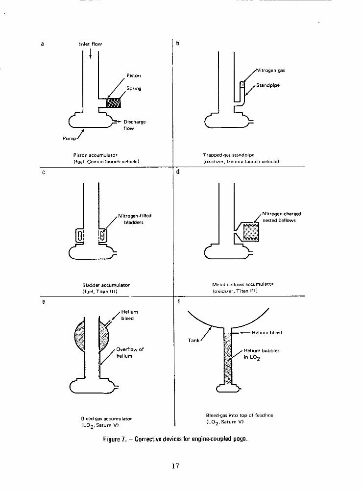
Schematics of engine-coupled pogo corrective devices that have been through hardware development are shown in figure 7. All were developed for the first liquid stages of vehicles; devices a, b, c, and e have been flown successfully. The Gemini fuel-piston accumulator suffers from excessive friction around the piston. The Gemini oxidizer standpipe has a large internal inertance which reduces its effectiveness because it produces an excessively low feedline second resonant frequency. The Titan 111 fuel-bladder accumulator and oxidizer metal-bellows accumulator represent advancements on the Gemini devices sincc frictional effects are minimized and the devices have low internal inertance. The Saturn V LO2 accumulator (fig. 7e) is also a low-inertance device, but it differs from the Titan 111 devices in its use of a continuous helium bleed to maintain the compliant gas. A proposal for helium injection at the top of the Saturn V LO2 feedline (fig. 7f) is based on reducing the acoustic velocity in the line resulting from entrainment of the helium. However, several feedline modes are lowered into the frequency range of concern, and achievement of stability could not be shown by analysis. Analytical and developmental considerations for the Titan devices are described in detail in reference 30; for the Saturn V devices, in references 21, 25, 31,and 61.
An undesirable interaction occurred between a Titan 111 fuel accumulator and the performance of the pump because of the accumulator’s location within the strong backflow field of the pump (ref. 30). Pump performance was altered, resulting in high static pressures within the accumulator, but the interaction was eliminated by incorporation of a small scoop (backflow deflector) to catch the backflow and redirect it into the pump before it reached the accumulator.
Tests have shown that low-rate gas overflow into the engine inlet, such as that designed to occur as shown in figure 7e, has not noticeably affected engine performance (ref. 61).
Two independent analytical studies (refs. 62 and 63) concluded that accumulators could effectively produce stability in Thor vehicles; reference 29 derives a tentative analytical design. An alternate proposal for a Titan fuel accumulator is discussed in reference 64. References 14, 16, 21, 31, 45, 65, and 66 describe types of corrective devices other than accumulators; in general, these either d o not have the assured effectiveness of accumulators or are less practical.
16
a Inlet flow
-.) Dtscharge
f
Piston accumulator (fuel, Gemini launch vehicle)
C
N itrogen-f illed bladders
Bladder accumulator (fuel,Titan Ill)
e I Helium
:.<< .... . .....-. ..... :.-.::.> ....:. .... : ..... 4 -...
Overflow of helium
Bleedgas accumulator (LO2, Saturn V )
Trappedgas standpipe (oxidizer, Gemini launch vehicle)
L r
Metal-bellows accumulator (oxidizer, Titan I I I )
f
Bleed-gas into top of feedline (LO2, Saturn V )
Figure 7. - Corrective devices for engine-coupled pogo.
17

One simple approach for suppressing ullage-coupled pogo is to increase the initial ullage volume. However, this may be unsatisfactory because the consequent reduction of onboard propellant leads to a loss in vehicle performance. Another approach is to alter the sense-line dynamics by means of a continuous flow through the line to obtain control over the composition and temperature of the gas and to increase dynamic-flow resistance. These approaches were applied to certain Atlas vehicles to reduce the severity of oscillations; they were not carried far enough to eliminate the instability. Other corrections proposed for ullage-coupled pogo are (1) adding an accumulator device to the sense-line, (2) redesigning the pneumatic regulator, and (3) eliminating the sense line by locating the regulator on the tank or by using a pressure transducer to provide an electrical signal to the regulator.
2.4 Flight Evaluation
Comprehensive collection and evaluation of flight cJta are needed to establish that pogo instability has been prevented. This requires proper instrumentation, data processing, and analytical procedures. In particular, inflight random data can be analyzed t o detect dynamic characteristics of the coupled structure-propulsion system. Reference 67 discusses the basis and applications for such analysis. Reference 52 demonstrates actual results of applications to the detection of pogo characteristics during flights of Titan vehicles using auto-spectral and cross-spectral density analyses of low-level random data. Natural frequencies of vehicle longitudinal modes were detected with great success. Specific deficiencies in a structural model were detected by a “node-frequency” method (ref. 52). Hydraulic resonant frequencies of feedlines with and without accumulators were detected with mixed success. The performance of a standpipe accumulator was well identified.
Spectrogram displays (sometimes called voice prints) have been employed with good effect t o detect time-varying resonant frequencies from flight data (ref. 68). A spectrogram is a graphical presentation of sinusoidal signal strength on a two-dimensional space of time versus frequency. One type of spectrogram, an intensity spectrogram, employs automatic gain control to search into the noise for the presence of a signal, and does not provide signal-amplitude information. Another type, the contour spectrogram, or contourgram, preserves amplitude information and displays lines of constant signal strength.
The development of the capability of directly determining system damping at various times of flight by introducing an excitation to the vehicle and observing the vehicle’s response deserves serious consideration. Such an approach has been discussed, but never studied thoroughly.
18

3. CRITERIA
The coupled structural and liquid-propulsion system of a space vehicle shall be stable, as determined by a suitable combination of analysis and test. The analysis shall be performed with linearized mathematical models for engine-coupled and ullage-coupled pogo, and prior to flight a space vehicle shall be considered stable when the analysis demonstrates an adequate margin of stability. Instability shall be eliminated by appropriate modification of the coupled system, when necessary. The accuracy of the mathematical models shall be substantiated by ground test and flights of suitably instrumented vehicles.
3.1 Mathematical Models
A linearized mathematical model of the coupled structural and propulsion systems shall be formulated to describe system dynamics over the frequency range of potential instability. The structural-system model shall describe the dynamics of the vehicle structure, including the effect of propellant in the tanks. The propulsion-system models shall describe the dynamics of pressure and flow for those elements applicable to the analysis of engine-coupled and ullage-coupled system stability.
3.2 Preflight Tests
Experimental data from preflight tests shall be obtained to establish values for the most significant model characteristics, particularly resonant frequencies, dampings, and gains associated with modes of the structural and propulsion systems.
3.3 Stability Analysis
Stability analysis, using mathematical models, shall be performed to cover the entire boost-flight regime. Uncertainties in the parametric values shall be accounted for by appropriate statistical means for establishing that the probability of a pogo instability during a space-vehicle flight is sufficiently small. As a minimum requirement, the nominal coupled system shall be stable a t all times of flight for the following two conditions imposed separately: (1) the damping of all structural modes is halved simultaneously (this corresponds to a damping gain margin of at least 6 dB), and (2) any phase shift up to +30 deg is applied simultaneously to each of the structural modes (this corresponds to a structural phase margin of 30 deg). When possible, the stability analysis shall be checked by a comparative analysis of the stability characteristics of closely related vehicles that have flown.
19

3.4 Corrective Devices or Modifications
If inadequate stability is shown, the mathematical model shall be used to determine corrections and the vehicle design shall be modified accordingly. Tests shall be performed during development t o demonstrate that the corrections do not decrease unacceptably the propulsion-system performance.
3.5 Flight Evaluation
Special data shall be acquired during initial flights of the space vehicle and processed to permit the verification of vehicle stability and the identification of significant characteristics of the system. Anomalous behavior shall be identified, indicated corrections shall be made to the mathematical model of the coupled system, and stabiiiiy shall be reevaluated in accordance with the criteria of Sections 3.3 and 3.4, using the corrected mathematical model.
4. RECOMMENDED PRACTICES
4.1 Mathematical Models
The mathematical model for pogo stability analysis should describe the linear dynamic behavior of the perturbed structure-propulsion system variables (i.e., accelerations, forces, flows, and pressures). I t is acceptable to assume that the system parameters can be “frozen” at any flight time to determine the existence of an instability at that time. A model should be formulated for the powered flight of each stage of the space vehicle.
Although there is no problem in apportioning elements to the structural or propulsion system for the ullage-coupled pogo model, for the engine-coupled pogo model it is recommended that the active-stage feedline hydraulics be included in the propulsion system model.
4.1.1 Structural Modeling
A mathematical model should be formulated t o describe the vibrational response of the space vehicle to pressure oscillations in the propulsion system. The model should deal predominantly with longitudinal structural dynamics, but should also include significant effects of coupling of longitudinal and lateral motion of the vehicle. Recommended practices for structural modeling are presented in general terms in references 2 and 3. The physical factors t o be modeled are the distribution Of mass and
20

i
stiffness of the structural elements and the interaction of the structure and the liquid in the vehicle tanks. Particular attention should be directed to the modeling of tanks and contained liquids. Lumped parameter or other simplified modeling techniques should not be used unless their applicability to the various vehicle tanks can be demonstrated. The demonstration should be based on data from experimental vibration of the tanks, or when such data are not available, on results from more sophisticated modeling, such as those given in references 36 to 39.
The structural model for engine-coupled pogo should especially include the following for the thrusting stage:
0 Detailed modeling of structure in the engine compartment which adequately characterizes motions that excite the propulsion system (such as motion of pumps and of bends in the line) and motions that significantly influence vehicle frequency response to thrust oscillation (such as the motion resulting from flexibility of engine trusses and support beams).
0 Tank modeling which establishes tank-bottom pressures and accounts for the presence of engine feedlines.
The structural model for ullage-coupled pogo should include tank structural response to fluctuating ullage pressure.
The description of the structural system for pogo stability analysis should be formulated in terms of significant vehicle natural modes of vibration as determined from the mathematical model and equivalent viscous damping of the modes (ref. 2). The significance of the natural modes should be evaluated by the method presented in the Appendix.
Structural modeling should be refined to the degree that i t can be used to determine the frequencies of the several most significant natural modes within an accuracy of 5 percent, as well as to determine accurate mode shapes and corresponding generalized masses. After modal analysis, the structural model should be reevaluated on the basis of whether or not its degree of refinement is appropriate for each significant mode. Modeling refinements should be introduced where it is believed that worthwhile improvements in accuracy can result. Those modeling improvements which, for a significant mode, could change a natural frequency by more than 5 percent or which could change a structural gain [e.g., eq. (A-1) in the Appendix] by more than 10 percent should be incorporated into the model of the structural system.
The damping values employed in structural modeling should be those applicable to low levels of excitation. Experimentally determined damping data for which nonlinear
21
effects have not been considered should be suspect, The value selected for the damping of any structural mode should not exceed 1 percent of critical damping unless there is strong experimental evidence that a higher damping exists.
4.1.2 Propulsion-System Modeling
The propulsion-system model should describe the dynamics of pressure and flow for at least the following elements for engine-coupled pogo:
0 Propellant line feeding engine
0 Pump
0 Pump-discharge system including engine-cooling lines, injector head, and injector orifices
0 Combustion chamber
For ullage-coupled pogo, the model should describe the dynamics of pressure and flow for at least the following elements:
Ullage volume
Ullage-pressure sense line
0 Pneumatic regulator
Ullage-pressurant supply line
Transfer functions for engine input-output variables should be used only when a simple physical model cannot be obtained. The physical representation of components is preferred because it (1) provides greater insight to the analyst, (2) permits direct modifications of component dynamics and of the engine-operating conditions, and (3) readily allows the retention of the engine’s internal variables (e.g., pump-discharge and injector pressures). Analytical information on internal variables is useful for comparison with ground- and flight-test data.
Particular attention should be given to modeling each tank-to-engine feedline, taking into account the following:
Propellant compressibility and radial flexibility of ducting in establishing the velocity of the propagation of disturbances in the propellant
22

0 Local compliance at a pump inlet caused by the presence of cavitation (Sec. 4.2.3)
Locally compliant devices, such as compensating bellows or accumulators
0 Distributed and local flow resistances
0 Effect of motions at area changes and bends
Unless experimental data indicate otherwise, acceptable modeling techniques for elements of the propulsion system are those described comprehensively for both types of pogo in reference 26 and, for engine-coupled pogo, in reference 27. Consideration should be given to the applicability of the types of components appearing in these references, but without disregarding the possibility that new components or modeling methods may be needed for the particular analysis being performed.
4.2 Preflight Tests
42.1 Structural Testing
Any portion of the vehicle’s structural system whose longitudinal dynamic model has not already been sufficiently verified should be subjected to modal testing (ref. 2). The test item should ideally be a full-scale replica of that portion of the vehicle. Careful attention should be directed to the determination of damping for low-amplitude vibration. If i t can be demonstrated that full-scale testing is nc?t practical, a dynamically scaled replica can be used. The accuracy of the representation of the natural modes of vibration in the mathematical model of the tested system should be evaluated in terms of the experimentally determined natural modes of the system. If discrepancies exist, the structure should be represented in terms of its experimentally determined natural modes.
During tests of a complete vehicle, data should be obtained for mechanical admittance (ref. 69) [i.e., engine velocity per unit thrust as defined by eq. (A-1) in the Appendix]. Those modes which satisfy equation (A-4) should be considered significant modes and subject to complete experimental definition. Admittance data should be acquired at a number of values of amplitude of applied force to establish the damping pertinent for infinitesimal excitation. Other modes involving significant local motions in the engine compartment should also be defined.
23

4.2.2 Normal Propulsion-Development Testing
Much of the experimental information necessary for dynamic modeling of the propulsion system should be based on the following data acquired during normal development testing:
0 Dynamic resistance for oscillations of turbulent flow should be based on a linearization of the proportional relationship of steady-pressure drop t o the square of steady-flow rate. No linearization is required if the flow is laminar, and the resistance to dynamic flow should be taken to be equal to the resistance to steady flow.
0 The resistance of a pump should be based on a linearization of the head rise versus flow characteristics at cons tan t inlet pressure.
The value of the characteristic velocity of combustion for perturbations in the flow of each propellant should be based on a linearization of the curve of characteristic velocity versus mixture ratio under steady-flow conditions.
References 26 to 28 should be consulted for more detailed discussion of how these parameters can be obtained.
An effort should be made to infer pump-cavitation compliance and dynamic-gain values from the analysis of random fluctuations during normal development tests of the turbopump or of the entire engine (ref. 52) before planning a program of special tests. If possible, such inferences should be made from tests of specimens having the same engine-feedline configuration as those of the flight vehicle. Turbopump or engine tests should be instrumented to record low-level fluctuating pressures at the pump inlet and discharge, and engine tests should be instrumented to record such pressures in the combustion chamber. Accelerations of the pump and of the test stand should also be measured.
.
Particular attention should be directed toward the evaluation of peaks in spectral analyses of the fluctuating pressures in an attempt to detect the resonant frequencies associated with the first, and possibly the second, modes of propellant oscillation in engine feedlines. Care should be taken not to confuse other resonant behavior, such as that due to structural resonances of the overall test configuration, with feedline resonances. Mathematical modeling of the coupled propulsion-structural system for a test configuration may be required to interpret properly the test results. Close-coupled narrow-range transducers and dc-signal removal should be used as required in data acquisition to improve the opportunity for successful detection of feedline resonances. A similar effort should be directed toward the detection of ullage sense-line resonant frequencies.
24

42.3 Special Propulsion Testing
In general, normal development testing cannot provide complete data for evaluating propulsion-system parameters. To evaluate these parameters properly, special test procedures, conditions, sequences, configurations, and instrumentation are required. Some of these are:
0 A series of steady engine-operating conditions covering the full flight-operating range of the propulsion system
0 Actual or dynamically modeled engine feedlines
0 Instruments specially ranged for measuring small oscillations at many points throughout the system
Signal processing, recording, and da!a reduction to provide accurate amplitude and phase content of the oscillations
Two approaches can be taken for special testing. The most certain approach is to perform pulsing tests of the propulsion system wherein the system is excited sinusoidally to obtain frequency-response information directly. An alternate approach is to perform nonpulsing tests to detect system characteristics by the analysis of low-level random oscillations (ref. 52). The thorough experimental definition of a new system should be based upon data from pulsing tests. This is particularly true for turbopumps, which may exhibit complex behavior, such as that reported in references 48 and 53. On the other hand, the influence of minor modifications of a basic system, already defiiled espefirnentally from pulsing tests, may possibly be determined from analysis of nonpulsing test data. Nonpulsing tests, although less costly to perform than pulsing tests, are more difficult to interpret, and greater attention must be given to designing the instrumentation system. Special nonpulsing tests should be performed only if the feedline’s resonant frequencies have been successfully detected during normal development tests (Sec. 4.2.2).
A pulsing test of an engine or a turbopump should be performed by sinusoidal hydraulic pulsing of the turbopump feedline (as opposed to pulsing the discharge line); the methods used in the efforts reported in references 46 and 53 are acceptable. No specific method is recommended for pulsing the ullage-pressurization system. The “noise floor” for the pulsing should be measured during periods when the system is not being excited by external means. In addition, an attempt should be made to detect system characteristics by the analysis of the low-level random oscillation data. This will serve to augment the knowledge gained from the pulsing portions of the tests.
25

Instrumentation should be provided for measuring the usual pressures (e.g., pump-inlet, discharge, injector, and chamber pressures, or ullage and regulator pressures). In addition, flush-mounted pressure transducers should be placed at a number of positions along the engine feedlines or along the ullage sense line, as applicable, to detect standing-wave effects. Standing-wave data will provide a basis for verifying the measured pump-inlet pressure fluctuations.
An accurate inference of pump-cavitation compliance from the feedline’s resonant frequencies observed during either pulsing or nonpulsing tests should be made; such inference requires a proper modeling of other relevant aspects of the system. It is particularly important that the distributed compliant and inertial properties of a long feedline and the dynamics of feedline devices should be defined. It is therefore recommended that sinusoidal hydraulic pulsing tests on a feedline be performed; it is usually acceptable to test a nonflowing feedline. The linc should be instrumented with pressure transducers along its length; instruments to measure significant structural motions of bends and of such devices as valves and compensating bellows should be used.
4.3 Stability Analysis
Pogo stability analyses that include the consideration of parameter uncertainties should be performed early in the vehicle-development process. The approximate method described in reference 28 is suggested for an initial investigation of the possibility of incurring engine-coupled instability, With this method, the significance of uncertainties in the system parameters can be initially assessed. As the vehicle progresses through its development phases and becomes better defined, increasingly detailed models of structure and propulsion systems should be constructed and stability analyses performed. Each repetition of stability analysis will provide information for a next round of refinements in the model, including the possible consideration of corrective modifications for achieving stability. Moreover, the process will contribute to advanced planning for the testing described in Section 4.2, and to the early consideration of alternative corrective modifications from the standpoints of implementation, reliability, and influence on the function of other elements of the system. Analyses should continue with updated parameters and increasing refinement until flight data and postflight analyses have demonstrated acceptable stability of the space vehicle.
Stability analyses should be performed at a sufficient number of flight times to establish completely the variation of system stability with time. Stability analyses should be performed either by determining closed-loop damping or by application of the complete Nyquist stability criterion for multiloop systems. The basis for describing the degree of stability in a given system mode should be a gain margin defined by the
26

I
structural damping required for neutral stability {N, divided into the actual structural damping, f . The damping gam margin (A, in decibels) is defined here as
For example, when actual structural damping ratio 5 equals 0.01 :
fN = 0.01 yields A = 0 dB (neutrally stable)
SN = 0.005 yields A = +6 dB (6 dB stable)
{N = 0.02 yields A = -6 d B (6 dB unstable)
Note that for stability, A has a positive value.
If the value of fN < 0, there is no concern about the stability of the system. That is, the system is stable even when all damping is removed from the structural modes. In effect, the propulsion system feedback provides a stabilizing influence rather than destabilizing.
To allow for the participation of any number of structural modes within a system mode, the same percentage change is made in each of the structural mode damping ratios f to achieve neutral stability of the coupled system.
In addition to the damping gain margin, which is a measure of the sensitivity of coupled-system stability to variation in damping of the structural modes, another measure which should be used in evaluating stability is the sensitivity of the stable coupled system to phase siiifts introduced into the structural modes. It is recom- mended that this sensitivity be measured in terms of a structural phase margin, defined as that minimum value of pure phase shift introduced simultaneously into the response of each structural mode that will barely cause the coupled system to become neutrally stable.
To provide a basis for evaluation of the mathematical model using flight data, the “mode shape” of any mode of the coupled structure-propulsion system having a potential for instability should be determined during the final set of prefight stability analyses. The mode shape expresses the relative amplitude and phase of the system variables (motions, forces, pressures, flows) for free oscillation of the system in a natural mode. It is directly obtainable from closed-loop analyses, and it can be approximated from open-loop results at the imposed condition of neutral stability during the determination of the damping gain margin. The approximation is expected to deteriorate in accuracy with increase in the degree of departure of the system’s actual stability from neutral.
27

For a closed-loop analysis of a system which is not highly stable, and where one structural mode is predominant over all others, an acceptable alternative to equa- tion (2) is (ref. 28)
where tc is the damping ratio of the closed-loop system and 5 is the damping ratio of the predominant structural mode. If tC > 5, the propulsion feedback is stabilizing, as it is when rN < 0.
It is recommended that the vehicle be considered stable when analyses performed show either ( I ) that the system is stable ( A > O ) under extrcme tolerance (worst-case) conditions (as defined in the conservative probabilistic process described in the following paragraphs), or (2) that the probability of an instability occurrence is less than an allowable value assigned on the basis of overall vehicle flightworthiness considerations.
The statistical analysis to determine instability probability ideally should be achieved by using a Monte Carlo process (ref. 60) involving the statistics of all the system parameters. The stability of a large number of randomly selected flights is determined, and an instability probability during a single flight is established for comparison with an allowable value a. Although direct, this may be a costly analytical process and should be undertaken only after simpler approaches (such as that described next) are shown to be inadequate.
The following process is recommended as a conservative approach t o determining whether the probability of instability during a flight is less than a:
1 .
2.
Determine ranges for the resonant frequencies of the various engine feedlines for a probability of instability occurrence in excess of a. This could require a Monte Carlo analysis for each feedline at each of a number of flight times; each analysis should consider statistical data on such parameters as net positive suction head for the pump, pump rotational speed, cavitation compliance, and compliance of an accumulator.
Establish one or more worst-stability cases (each at an individual time of flight) using feedline frequencies within the above ranges and ranges for structural frequencies based upon the same value of a, but nominal values for other parameters.
28

3 . Perform stability analyses for the worst cases cstablished above.
4. The system is adequately stable if the stability margin for each of these cases is sufficiently large to overcome uncertainties in such parameters as structural damping, structural gain, thrust coefficient, and characteristic velocity. (These particular parameters contribute to system gain in a linear fashion and so a root-sum squaring process can give their combined effect.)
This process will be sufficient if it shows stability; but if an instability is shown, the circumstances may suggest the pursuit of a more comprehensive statistical analysis before making hardware corrections.
Often, a space vehicle is similar to one or more of its predecessors whose inflight-stability behavior has been demonstrated. In such a case, the validity of an overall analysis method for a new design should be checked by performing comparable analysis on the similar predecessor vehicles. When the results of the analysis of the predecessor vehicles are inconsistent with the observed flight performance, the model being used to evaluate the stability of the vehicle under current design should be reassessed.
4.4 Corrective Devices or Modifications
Close-coupled accumulators for engine feedlines should be considered in any study of potential corrective modifications to achieve vehicle stability for engine-coupled pogo. In particular, serious consideration should be given to at least one of the following design concepts shown in figure 7: the flexible-bladder (c) types or the metal-bellows (d) types developed for Titan I11 vehicles (ref. 30), or the gas-injection (e) type developed for the Saturn V (ref. 25). Consideration should be given in the initial vehicle design phases to allow for possible future installation -of such devices.
The accumulator should be located as close to the engine as practical. If possible, however, the region within at least one feedline diameter from the pump inlet should be avoided so that interaction with pump performance is minimized.
The accumulator should be tentatively sized by requiring that it reduce the first feedline natural frequency wl* to a value less than the natural frequency of any significant structural mode. This condition is expressed as
29

where
and wn is the natural frequency of any structural mode shown to be significant for the propellant involved by use of equation (A-4) in the Appendix.
This expression is derived from material in reference 28 by making the same assumptions as were made for equation (A-4) in the Appendix, except that the fraction of thrust canceled by force due to pressure at engine inlet D is assumed not to be equal to zero; also, for simplicity, the inertance of the discharge line is ignored. A more refined sizing can be obtained ( 1 ) from reference 28 by eliminating the assumptions made above, (2) from reference 29, or (3) by an iterative process involving stability analyses of the full analytical model.
A development program for integrating accumulators into a propulsion system should include at least the following tests:
0 Pulsing tests of the flight-configuration feedline with the accumulator installed and no propellant flow. Data from a comparable test without the accumulator should be available for reference. The purpose is to verify the dynamic model of the accumulator over its range of operating pressure.
Simulation of any severe pressure transients at the accumulators arising from events such as prevalve opening and engine ignition (ref. 30). The purpose is to determine the ability of the accumulator t o be operational after such surges.
Pump functional tests with the accumulator in place. These are required only if the accumulator is in the “near field” of a pump inlet. The purpose is to detect any biasing of pump performance caused by the accumulator and any effect of the pump on operating pressure within the accumulator.
Functional demonstration tests of the entire flight-configuration propulsion system with and without the accumulator in place. A primary purpose of these tests is to verify that interactions between the accumulator and the propulsion system, such as pump/accumulator intereffects or effects of gas bleed into the engine inlet, are not detrimental. Another purpose is t o verify the predicted change in resonant frequencies of the feedlines. A test without an accumulator is required to provide reference data. The tests should be
30

instrumented properly .to enable the detection of feedline resonant frequencies from spectral analyses of low-level fluctuating pressures. When possible, flight or equivalent instrumentation should be installed in addition to special instrumentation during the test.
Provision should be made for inflight instrumentation needed to monitor accumulator performance early in the accumulator-development program. Instrumentation on the accumulator should be considered as an integral part of the accumulator during its development .
A study of corrective modifications for ullage-coupled instability should consider the following possibilities:
0 A larger initial ullage volume
0 Creation of a purge flow through the sense line (to achieve a known temperature and gas composition along the line and to increase the dynamic resistance of the line)
Addition of an accumulator to the sense line
0 Elimination of the sense line
Alteration of regulator characteristics
4.5 Flight Evaluation
The space vehicle should be adequately instrumented for inflight detection of the amplitude and relative phase of oscillations in the frequency range of interest. Time histories of longitudinal acceleration and propulsion-system pressures during flight should be scrutinized for indications of the gradual growth and decay of the vibration that characterizes pogo instability. If there is such an indication and it cannot be explained by association with a vehicle event, the vehicle is presumed to be unstable. The rate of change of the envelope of oscillations should not be used to determine the degree of instability of the system.
If an instability occurs in flight, the relative amplitude and phase of oscillations throughout the structural and propulsion systems indicate the shape of the unstable mode of the coupled system. This shape may be distorted at high amplitudes of oscillation due to nonlinear effects. When the system is stable and sufficient coherency exists among the random oscillations of the system variables, spectral analyses should be performed to determine amplitude and phase relationships among variables (ref. 67).
31

Mode shapes determined from the flight data should be compared with analytical predictions for evaluation of the mathematical model. Mode shapes determined in flight should not be used to indicate the degree of stability or instability of the coupled system.
Recordings of the structural and propulsion system oscillations resulting from such transient events as liftoff and engine ignitions and shutdowns should be scrutinized for evidence of a clearly defined free decay following the event. An observed simple exponential decay is a direct indication of the damping of the associated coupled-system mode at that time and should be used to check results of the mathematical model.
The initial several flights of the vehicle should be specially instrumented to obtain data which can be used to verify the mathematical niodel used for pogo stabiiity analysis. The absence of an instability on an initial flight is far from a guarantee that the vehicle is adequately stable; the degree of stability cannot be quantitatively determined from flight data. Only a well-verified mathematical model can provide confidence in the inherent stability of the vehicle.
At least the following instrumentation should be used in flight tests:
A number of accelerometers ranged to detect low-level oscillatory motions; for example, at positions such as gimbal blocks and the prime structure between major vehicle tanks, and at positions of prime interest on the spacecraft and in the propulsion system (i.e., at positions to measure motion of a pump, a propellant tank shell, or a pneumatic regulator).
One or more accelerometers ranged to detect a severe pogo vibration.
Transducers ranged to detect low-level oscillatory pressures in the propulsion system; for example, pump-inlet and discharge and combustion-chamber pressures for engine-coupled pogo, and ullage and regulator pressures for ullage-coupled pogo.
Transducers to measure significant steady operating conditions for the propulsion system; for example, pressures and temperatures at pump inlets, in ullage volumes, and along sense lines for ullage regulation.
Those instruments required to monitor the performance of devices placed o n the vehicle to suppress pogo instability
i
32

When possible, spectrographic displays should be used for identifying system frequency variations with time (ref. 68). Spectral analyses of low-level random accelerations should be made to permit an evaluation of the longitudinal structural model throughout boost flight (ref. 52). If significant discrepancies between predicted and observed natural frequencies exist, the method of node-frequency detection in reference 52 should be employed when possible to derive base-fixed longitudinal natural frequencies for sections of the vehicle (i.e., natural frequencies for end portions of the vehicle under fixed conditions at the junction with the remainder of the vehicle). I t is recommended that accelerometers with ranges of k1 g, or less, and which are not responsive to steady acceleration, be utilized for this purpose.
Spectral analyses of low-level random-pressure oscillations should be used to detect resonant frequencies of lines and other significant frequency-response information (e.g., the ratio of pump-inlet pressure to pump acceleration, the ratio of pump inlet to discharge pressures, and the ratio of pressure sensed by the regulator to the actual ullage pressure).
All pogo-related propulsion and structural instrumentation and associated telemetry and data-reduction procedures should be completely evaluated prior to flight to demonstrate (1) amplitude and phase accuracy over the frequency range of interest, (2) sufficient signal/noise ratios, and (3) lack of “aliasing” or “foldback” of sampled data. A final verification should be performed when possible by incorporating flight-type transducers into ground testing, and then performing signal processing and data-reduction procedures identical to those which will be used for the flight measurements.
Deficiencies in the mathematical model of the structural or propulsion system should be corrected in accordance with observed flight behavior. A:: appraisal of the mathematical model should cover all pertinent parameters; for example:
Natural frequencies of significant structural modes
Base-fixed natural frequencies of longitudinal structural modes for sections of the vehicle
Hydraulic resonant frequencies of feedlines
The interrelations of propulsion-system variables and their relation to the structural vibration
A postflight pogo-stability analysis should then be performed using the upgraded mathematical models. In addition, pertinent engine-operational parameters for the
33

flight (such as operating pressures and pump-cavitation indexes) should be used. Further correction of the mathematical model is required if conflict results between postflight and flight observation on the presence or absence of an instability, or if indications of the damping of a system mode after a transient event differ from prediction. I t is recommended that the vehicle be judged sufficiently stable when (1) pogo instability did not occur during the initial several flights and (2) if the mathematical model has been upgraded, postflight statistical stability analyses using this model show an acceptably low probability of instability occurrence.
34

APPENDIX
Assessment of Significance of Structural Modes
The mechanical admittance or mobility Y (ref. 69) for a single natural mode of the vehicle's structural system in terms of the velocity of the engine ]Ie per unit of oscillating thrust T is given by [ e.g., eq. (2) of ref. 281 :
@e@T M , G e = - 'e Ges
T Y(s) = - =
s2 + 2{wns + on2
The engine velocity should be that which is the primary excitation for the engine hydraulics (e.g., the longitudinal velocity of the pump in the system of fig. 3).
Under sinusoidal conditions at the natural frequency (s = iun) , the admittance has a maximum value Ym given by
A mode can be eliminated from consideration by establishing that the coupled system would be quite stable, even for a frequency coincidence of that mode with a feedline resonance. Considering an elemental system consisting of one prope!!ant system and one structural mode, an approximate relationship for neutral stability at frequency coincidence is [from eq. (49) of ref. 281 :
Y m B ( l -D)Z 1 (A-3 1
where B is the thrust per unit engine velocity at the frequency of a feedline resonance
and D is the fraction of the thrust nullified by the opposing longitudinal force due to engine inlet pressure [ eq. (4)].
35

APPENDIX
It should be assumed that a mode is significant if the left side of equation (A-3) has a value above 3 . Accounting for the possibility of j engines, the retention of a structural mode is recommended when the Ym values for the engines are sufficiently large that the following expression is satisfied for either propellant:
Z Y m B > + J
('4-4)
Equation (A-4) contains these additional simplifications which will most likely have the net effect of lesscning the possibility of ignoring a significant structural mode: (1) D = 0, (2) there is no mixture-ratio effect on characteristic velocity of the thrust chamber, and (3) gross motion .of propellant in tank equals that of the engine. Any of these simplifications can be relaxed by use of relationships in reference 28.
36

1.
2.
3.
4.
5.
6.
7.
8.
9.
10.
11.
REFERENCES
Rubin, S.: Prevention of Coupled Structure-Propulsion Instability (Pogo) on the Space Shuttle. Space Transportation System Technology Symposium (Cleveland), Vol. I1 - Dynamics and Aeroelasticity, NASA TM X-52876, 1970, pp. 249-262.
Anon. : Natural Vibration Modal Analysis. NASA Space Vehicle Design Criteria (Structures), NASA SP-8012, 1968.
Anon. : Structural Vibration Prediction. NASA Space Vehicle Design Criteria (Structures), NASA SP-8050, 1970.
Anon.: Flutter, Buzz, and Divergence. NASA Space Vehicle Design Criteria (Structures), NASA SP-8003, 1964.
Anon.: Panel Flutter. NASA Space Vehicle Design Criteria (Structures), NASA SP-8004, 1965.
Anon.: Staging Loads. NASA Space Vehicle Design Criteria (Structures), NASA SP-8022, 1969.
Anon.: Transient Loads from Thrust Excitation. NASA Space Vehicle Design Criteria (Structures), NASA SP-8030, 1969.
Goldman, R. L.; and Prause, R. H.: Longitudinal Oscillation Instability Study - POGO. Rept. ER 13374, The Martin Co., Dec. 1964. (Available from DDC as AD 465 188.)
Davis, W. F.; Lynch, T. F.; and Murray, T. R.: Thor 20 Cycle Longitudinal Oscillation Study. The Shock and Vibration Bull. No. 34, pt. 2, Dec. 1964, pp. 177-196. (Also Paper no. 3099, Douglas Aircraft Co., Oct. 1964.)
Hams, R. D.: Nonlinear Dynamic Analysis of the SLV-3 Liftoff Longitudinal Oscillation. Rept. GDC-DDE 66-186, General Dynamics Corp., Mar. 1967. (Available from DDC as AD 862207.)
Walker, J. H.; Winje, R. A.; and McKenna, K. J.: Investigation of Low Frequency Longitudinal Vibration of the Titan I1 Missile During Stage I Flight. Rept. 6438-6001-RU-000, Space Technology Lab., Mar. 1964; Addendum, June 1964. (Available from DDC as AD 460708 and AD 460709, respectively.)
37

12.
13.
14.
15.
16.
17.
18.
19.
20.
21.
McKenna, K. J.; Walker, J. H.; and Winje, R. A.: Engine-Airframe Coupling in Liquid Rocket Systems. J . Spacecraft Rockets, vol. 2, no. 2, Feb. 1965, pp. 2 54-2 56.
Bikle, F. E.; and Rohrs, J . B.: Dynamic Analysis of Longitudinal Oscillations of SM-68B Stage I (POGO). Rept. CR-64-7 1, The Martin Co., Mar. 1964. (Available from DDC as AD 46 1795 .)
Rubin, S.: Instability Model of Missile Longitudinal Oscillation Due to Propulsion Feedback. Rept. TOR-269(4 126)-28, The Aerospace Corp., Sept. 1964. (Available from DDC as AD 45821 1 .)
Anon.: Final Technical Report, Thor Block 2 Test Program (20 cps Oscillation Problem). Rept. R-3 128, North Americali Aviation, Inc., Aug. 196 I .
Davis, W. F.; Keeton, D. L.; and Lynch, T. F.: Thor Longitudinal Oscillation Study. Rept. SM-45009, Douglas Aircraft Co., Mar. 1964. (Available from DDC as AD 4609 1 1 .)
Radovcich, N. A.: Analytical Model for Missile Axial Oscillation Induced by Engine-Structural Coupling. Presented at AIAA Unmanned Spacecraft Meeting (Los Angeles), Mar. 1-4, 1965. (Also Paper no. A65822, Lockheed Missiles & Space Co., Mar. 1964).
Davis, W. F.; and Keeton, D. L.: Preliminary Longitudinal Stability Study for DSV-2L. Rept. SM-52278-A, Douglas Aircraft Co., May 1966.
Rose, R. G.; and Harris, R.: Dynamic Analysis of a Coupled Structural/ Pneumatic System Longitudinal Oscillation for Atlas Vehicles. AIAA Paper no. 64-483, 1964.
Wolfe, K. E.; Austin, E. A.; and Nelson, R. L.: Study of Longitudinal Oscillations During Flights of Atlas Space Launch Vehicles. Rept. AER 64-2, North American Aviation, Inc., Mar. 1964.
Meisenholder, S. F.; and Bickford, L. L.: “POGO” Analysis of the Saturn Propulsion System. Rept. AMDR 9635-037, Aerojet-General Corp., Apr. 1967. (Available from STIF* as X67-17093.)
~~
*NASA Scientific and Technical Information Facility
38
1

22. Bikle, F. E.: An Investigation of Longitudinal Oscillation Instabilities of the Saturn V LOR Vehicle. Rept. CR-66-45, The Martin Co., July 1966.
23. Winje, R. A.: Apollo Saturn Space Vehicle POGO Analysis. Rept. 11 176-HOO1- RO-OO, TRW Systems Group, July 1968 (available from STIF as X69-12457); also Repts. 1 1176-H001-RO-01 and -02, Addenda 1 and 2, Sept. and Dec. 1968 (available from NTIS* as N69-14836 and from STIF as X69-15366).
24. Anon.: Summary and Assessment of AS-503 Pogo Suppression. Rept. MPR SATURN-68-2, NASA Marshall Space Flight Center, Dec. 1968.
25. Rich, R. L.: Saturn V POGO and a Solution. Presented at AIAA Structural Dynamics and Aeroelasticity Specialist Conf. (New Orleans), published in volume on Structural Dynamics, Apr. 16-17, 1969, pp. 3241.
26. Rose, R. F.; Staley, J. A.; and Simson, A. K.: A Study of System-Coupled Longitudinal Instabilities in Liquid Rockets. AFRPL-TR-65-163, pts. I and 11, Air Force Rocket Propulsion Lab., Sept. 1965.
27. Goldman, R. L.; and Reis, G. C.: A Method for Determining the Pogo Stability of Large Launch Vehicles. Rept. TR-69-7G, Research Institute of Advanced Studies, June 1969.
28. Rubin, S.: Longitudinal Instability of Liquid Rockets Due to Propulsion Feed- back (POGO). J. Spacecraft Rockets, vol. 3, no. 8, Aug. 1966, pp. 1188-1 195.
29. Lewis, W.: Simplified Analytical Model for use in Design of Pump-Inlet Accumulators for the Prevention of Liquid-Rocket Longitudinal Oscillation (POGO). NASA TN D-5394, 1969.
30. Norquist, L. W. S.; Marcus, J. P.; and Ruscio, D. A.: Development of Close- Coupled Accumulators for Suppressing Missile Longitudinal Oscillations (POGO), Paper no. 69-547, presented at AIAA Fifth Propulsion Joint Specialists’ Conf. (Colorado Springs, Colo.), June 9-1 3, 1969.
31. Bikle, F. E.; Fidler, L. E.; Hendricks, T. G.; et al.: System Coupled Dynamic Instability, Amplitude Limiting Analysis and Evaluation Report. AFRPL-TR- 6 8 4 1 , pts. I and 11, Air Force Rocket Propulsion Lab., Mar. 1968.
~~ * National Technical Information Service.
39

32. Staley, J. A.: Determination of Longitudinal Vibration Modes. Vol. I1 of Dynamic Stability of Space Vehicles, NASA CR-936, 1967.
33. Pengelley, C. D.: Natural Frequency of Longitudinal Modes of Liquid Propellant Space Launch Vehicles. J. Spacecraft Rockets, vol. 5, no. 12, Dec. 1968, pp. 1425-1431.
34. Pinson, L. D.; and Leonard, H. W.: Longitudinal Vibration Characteristics of I / 1 O-Scale Apollo/Saturn V Replica Model. NASA TN D-5 159, 1969.
35. Archer, J. S.; and Rubin, G. P.: Improved Longitudinal Response Analysis for Axisymmetric Launch Vehicles. NASA CR-345, 1965.
36. Palmer, J . H.; and Asher, G. W.: Calculation of Axisymmetric Longitudinal Modes for Fluid-Elastic Tank-Ullage Gas Systems and Comparison with Model Test Results. Proc. AIAA Symposium on Structural Dynamics and Aeroelasticity (Boston), Aug. 30-Sept. I , 1965, pp. 189-193.
.,
37. Coale, C. W.: Axisymmetric Vibrations of a Cylindrical-Hemispherical Tank Partially Filled with a Liquid. AIAA J., vol. 7, no. 2, Feb. 1969, pp. 235-243.
38. Luk, C.: Finite Element Analysis for Liquid Sloshing Problems. Rept. AFOSR-69-1504TR, Mass. Inst. of Techno]., Aug. 1969.
39. Kroll, R. J.; and Ventre, G. G.: Vibration Characteristics of a Cylinder Partially Filled with Liquid with an Attached Elastic Drain Pipe. NASA CR-1490, 1970.
40. Glaser, R. F.: Longitudinal Mass-Spring Modeling of Launch Vehicles. NASA TN D-537 1, 1969.
41. Gerus, T. F.; Housely, J. A.; and Kusic, G.: Atlas-Centaur-Surveyor Longitudinal Dynamics Tests. NASA TM X-1459, 1967.
42. Carden, H. D.; and Raney, J. P.: An Experimental and Analytical Study of the Longitudinal Vibration of a Simplified Thor Vehicle Structure. NASA TN D-3632, 1966.
43. Schoenster, J . A.; and Clary, R. R.: Experimental Investigation Of the Longitudinal Vibration of a Representative Launch Vehicle with Simulated Propellants. NASA TN D-4502. 1968.
40

44.
45.
46.
47.
48.
49.
50.
51.
52.
53.
54.
55.
Fashbaugh, R. H.; and Streeter, V. L.: Resonance in Liquid Rocket Engine Systems. J. Basic Engineering, vol. 87, no. 4, Dec. 1965, pp. 101 1-1017.
Anon.: Apollo Pogo Problem Special Study. Rept. R-7753, North American Rockwell Corp., May 1969.
Brown, R. H.; Fashbaugh, R. H.; Shupert, T. G.; and Ward, T. L.: Dynamic Characteristics Tests of YLR-87-AJ-5 Rocket Engine Turbopump and Associated Equipment. Contract AF 04(647)-576, CCN 408, The Martin Co., Jan. 1964. (Available from DDC as AD 427229.)
Anon.: Investigation of the Transfer of Oscillations through the YLR 87-AJ-5 Engine Systems. Rept. BSD TR-65-54, Aerojet-General Corp., Mar. 1965. (Available from DDC as AD 46 1286.)
Bikle, F. E.; Fidler, L. E.; and Rohrs, J. B,: A Study of System Coupled Instability Techniques. AFRPL-TR-66-143, pts. I and 11, Air Force Rocket Propulsion Lab., July 1966.
Bramblett, G.; Knowles, R.; and Sack, L.: Pump Cavitation as a Factor in Vehicle Longitudinal Vibration. Paper no. 66-559, presented at AIAA Second Propulsion Joint Specialist Conf. (Colorado Springs, Colo.), June 13-1 7, 1966.
Anon.: Engine System Transfer Functions for Support of S-V Vehicle Longitudinal Stability (Pogo) Analysis Program. Rept. R-6929, North American Aviation, Inc., Mar. 1967.
Wagner, R. G.: Titan I1 Engine ‘l’ransfer Function Test Results. Rept. TOR-0059(647 1)-9, The Aerospace Corp., Jan. 197 1.
Wagner, R. G.; and Rubin, S.: Detection of Titan Pogo Characteristics by Analysis of Random Data. Proc. ASME Symposium on Stochastic Processes in Dynamical Problems (Los Angeles), Nov. 1969, pp. 51-62.
Anon.: Investigation of 17-Hz Closed-Loop Instability on S-I1 Stage of Saturn V. Rept. R-7970, North American Rockwell Corp., Aug. 1969.
Ghahremani, F. G.: Turbopump Cavitation Compliance. Rept. TOR-0059 (6531-01)-2, The Aerospace Corp., Sept. 1970.
Chestnut, H.; and Mayer, R. W.: Servomechanisms and Regulating System Design. Vol. I, John Wiley & Sons, Inc., 1959.
41

1
56.
57.
58.
59.
60.
61.
62.
63.
64.
65.
66.
67.
Fox, L.: An Introduction of Numerical Linear Algebra. Clarendon Press (Oxford), 1964.
Payne, J. G.: Pogo Stability Analysis Program. Rept. TOR-0059(6 122-30)-9, The Aerospace Corp., 1970.
Lancaster, P.: Lambda-Matrices and Vibrating Systems. Secs. 1.6, 1.7, and 7.9, Pergamon Press, Ltd. (London), 1966.
Anon.: Effects of Structural Flexibility on Launch Vehicle Control Systems. NASA Space Vehicle Design Criteria (Guidance and Control), NASA SP-8036, 1970.
Shreider, Yu. A., ed.: The Monte Carlo Method. Pergamon Press, Ltd. (London), 1966.
Worlund, A. L.; Glasgow, V. L.; Norman, D. E.; and Hill, R. D.: The Reduction of Pogo Effects by Gas Injection. Paper no. 66-560, presented at AIAA Second Propulsion Joint Specialist Conf. (Colorado Springs, Col.), June 13-17, 1966.
Woodward, G. B.; and Gunderson, D. H.: Evaluation of High-Compliance Device to Suppress 20-cps Longitudinal Oscillations in the Thor Vehicle (U). Rept. TER-65-2, North American Aviation, Inc., July 1965. (Confidential)
Davis, W. F.; Keeton, D. L.; Lynch, T. F.; Novak, W. W.; and Saxton, H. A.: Feasibility Study of Compliant Devices t o Eliminate Longitudinal Instability. Rept. SM-49005, Douglas Aircraft Co., Aug. 1965.
Schumacher, R. N.; and Goldman, R. L.: GLV Pogo Study - Low Pressure Toroidal Fuel Accumulator. Rept. LV-325, The Martin Co., Jan. 1964.
Lewis, W.; and Blade, R. J.: Analysis of Effect of Compensating-Bellows Device on a Propellant Line as a Means of Suppressing Rocket Pump Inlet Perturbation. NASA TN D-2409, 1964.
Ruscio, D., et al: Report on Titan 11, Stage I Oxidizer Lossy Suction Line Program. Contract AF 04(647)-576, CCN 542, The Martin Co., Jan. 1964.
Bendat, J . S.; and Piersol, A. G.: Measurement and Analysis of Random Data. John Wiley & Sons, Inc., 1966.
42

68.
69.
Ackerman, A. T.; Ferrara, L. A.; and O’Connor, J. J . : Contour Spectrograms for Pogo Analysis - Case 320. Rept. B70 04034, Bellcomm Inc., Apr. 1970.
Hixson, E. L.: Mechanical Impedance and Mobility. Vol. I, Ch. 10, Shock and Vibration Handbook, C. M. Harris and C. E. Crede, eds., McGraw-Hill Book Co., Inc., 1961.
43

SYMBOLS
AS
B
C*
Ca
‘b
c f D
Ge
g
h
ISP
1
k
La
Lb
LS
M
m+ 1
R
S
area of propellant flow into engine, in.2 (m2)
thrust per engine velocity at feedline resonance, lb sec/in. (N sec/m)
characteristic velocity of combustion chamber, in./sec (m/sec)
compliance of accumulator, in.3 /psi (m5 /N)
compliance at pump inlet, in.3 /psi (m5 /N)
thrust coefficient
fraction of thrust canceled by force caused by pressure at engine inlet
structural gain, in./lb sec2 (m/N sec2 )
standard acceleration of gravity, 386 in./sec2 (9.81 m/sec2)
liquid level in tank above pump inlet, in. (m)
specific impulse, sec (Specific impulse is defined as thrust divided by total weight flow of propellant. It can also be written in the form Isp = C*Cf/g.)
imaginary unit, J--T- cavitation index, dimensionless
internal inertance of accumulator, sec’ /in.’ (sec2 /m’ )
inertance of feedline from pump to accumulator, sec’ /in.* (sec2 /m2 )
inertance of entire feedline, sec’ /in.’ (sec’ /m’ )
generalized mass, lb sec2 /in. (kg)
pump gain
total resistance of engine, sec/in.2 (sec/m2 )
Laplace variable, radlsec
45

T thrust, Ib (N)
engine velocity, in./sec (mlsec)
mechanical admittance, in./lb sec (m/N sec)
maximum mechanical admittance, in./lb sec (m/N sec)
maximum allowable probability of instability during a flight
damping-gain margin, dB
damping ratio (fraction of critical damping) of a structural mode
closed-loop damping ratio
structural damping ratio required for neutral stability
propellant weight density, lb/in.3 (N/m3 )
modal displacement of engine
modal displacement of thrust point
natural frequency of a structural mode, rad/sec
first natural frequency of engine feedline, rad/sec
second natural frequency of engine feedline, radlsec
summation

SP-800 1
SP-8002
SP-8003 SP-8004 SP-8005 SP-8006
SP-8007
SP-8008 SP-8009 SP-80 10 SP-80 1 1
SP-80 12 SP-80 13
SP-80 14 SP-80 15
SP-80 1 6
1 SP-80 17 r
SP-80 18
SP-80 19
SP-8020 SP-802 1
SP-8023 SP-8024
1 i 1
SP-8025
NASA SPACE VEHICLE DESIGN CRITERIA MONOGRAPHS ISSUED TO DATE
(Structures)
(Structures)
(Structures) (Structures) (Environment) (Structures)
(Structures)
(Structures) (Structures) (Environment) (Environment)
(Structures) (Environment)
(Structures) (Guidance and Control) (Guidance and Control) (Environment)
(Guidance and Control) (Structures)
(Environment) (Environment)
(Environment) (Guidance and Control) (Chemical Propulsion)
Buffeting During Atmospheric Ascent, May 1964 - Revised November 1970
Flight-Loads Measurements During Launch and Exit, December 1964
Flutter, Buzz, and Divergence, July 1964 Panel Flutter, July 1965 Solar Electromagnetic Radiation, June 1965 Local Steady Aerodynamic Loads During Launch
Buckling of Thin-Walled Circular Cylinders,
Prelaunch Ground Wind Loads, November 1965 Propellant Slosh Loads, August 1968 Models of Mars Atmosphere (1967), May 1968 Models of Venus Atmosphere ( 1968), December
Natural Vibration Modal Analysis, September 1968 Meteoroid Environment Model - 1969 [Near Earth
Entry Thermal Protection, August 1968 Guidance and Navigation for Entry Vehicles,
Effects of Structural Flexibility on Spacecraft
Magnetic Fields - Earth and Extraterrestrial, March
Spacecraft Magnetic Torques, March 1969
and Exit, May 1965
September 1965 - Revised August 1968
1968
to Lunar Surface], March 1969
November 1968
Control Systems, April 1969
1969
Buckling of Thin-Walled Truncated Cones,
Mars Surface Models [ 19681 , May 1969 Models of Earth’s Atmosphere (1 20 to 1000 km),
Lunar Surface Models, May 1969 Spacecraft Gravitational Torques, May 1969
September 1968
May 1969
Solid Rocket Motor Metal Cases, April 1970
47

SP-8026
SP-8 0 2 7
SP-8028
SP-8029
(Guidance and Control) (Guidance and Control) (Guidance and Control) (Structures)
SP-8030 (Structures)
SP-803 1 SP-8032
(Structures) (Structures)
SP-803 3
SP-80 3 4
SP-8035 SP-8036
SP-8037
SP-8038
SP-8040
SP-8042 SP-8046
SP-8047
SP-8050 SP-8053
SP-8054
(Guidance and Control) (Guidance and Control) (Structures) (Guidance and Control) (Environment)
(Environment)
(Structures)
(Structures j (Structures)
(Guidance and Control) (Structures) (Structures)
(Structures)
Spacecraft Star Trackers, July 1970
Spacecraft Radiation Torques, October 1969
Entry Vehicle Control, November 1969
Aerodynamic and Rocket-Exhaust Heating During
Transient Loads From Thrust Excitation, February
Slosh Suppression, May 1969 Buckling of Thin-Walled Doubly Curved Shells,
Spacecraft Earth Horizon Sensors, December 1969
Launch and Ascent, May 1969
1969
August 1969
Spacecraft Mass Expulsion Torques, December 1969
Wind Loads During Ascent, June 1970 Effects of Structural Flexibility on Launch Vehicle
Control Systems, February 1970 Assessment and Control of Spacecraft Magnetic
Fields, September 1970 Meteoroid Environment Model - 1970 (Inter-
planetary and planetary), October 1970 Fracture Control of Metallic Pressure Vessels, May
1970 Meteoroid Damage Assessment, May 1970 Landing Impact Attenuation for Non-Surface-
Spacecraft Sun Sensors, June 1970 Planing Landers, April 1970
Structural Vibration Prediction, June 1970 Nuclear and Space Radiation Effects on Materials,
Space Radiation Protection, February 197 1 February 197 1
48 NASA-Langley, 1971 - 32
~ ~~

NATIONAL AERONAUTICS AND SPACE ADMINISTRA~ ION
WASHINGTON, D. C. 20546
OFFICIAL BUSINESS FIRST CLASS MAIL
POSTAGE A N D FEES PAIC NATIONAL AERONAUTICS A
SPACE ADMINISTRATION
If Undeliverable (Section 1: Postal Manual ) Do Not Ret
t