principles of steam-in- place - pharmtechfiles.pharmtech.com/alfresco_images/pharma/2014/08/... ·...
TRANSCRIPT
s40 Pharmaceutical Technology FILTRATION 2004 www.pharmtech.com
dequate configuration of steam-in-place (SIP) systems is vitaland must be considered at the
early conception stage of the plant.The critical requirements associatedwith SIP include proper steam dis-tribution, noncondensable gases re-moval, and continuous condensateelimination. Good engineeringpractices, adequate piping design,steam traps, valves, and monitoringinstrumentation are essential to en-suring SIP validation.
Gas filter engineeringSystem design, installation, and stan-dard operating procedure. Vent filtersare required for the sterile introduc-tion of air or nitrogen during andafter the process of vessel steriliza-tion. Gas filters are made of hy-drophobic materials such as PTFE toprevent blockage by humidity dur-ing use. Therefore, condensate mayaccumulate on the membrane dur-ing SIP and produce blind filters. Insuch circumstances, the steam nolonger passes through the mem-brane, leading to incorrect steriliza-tion. The filter housing must there-
Principles of Steam-In-PlaceJean-Marc Cappia
A
MIL
LIP
OR
E C
OR
PO
RA
TIO
N
Steaming-in-place (SIP) is awidely adopted method for thein-line sterilization of processingequipment. The main advantageof SIP relies on manipulationreduction and aseptic connect-ions that might compromise theintegrity of the downstreamequipment.
Jean-Marc Cappia is theprogram director for high filtrationperformance solutions in theBioPharmaceutical Division ofMillipore Corporation, 80 AshbyRoad, Bedford, MA 01730, tel.781.533.2219, [email protected].

Pharmaceutical Technology FILTRATION 2004 s41
fore be designed and in-stalled for correct drainageof condensate, with the inletsterile side of the cartridgefitted on the sterile vessel.This setup is preferred, sincethe housing closure as wellas the connections to ventand drain valves may pres-ent risks of leakage on theupstream side of the filter. Areverse mounting would re-sult in the filter bypass andwould compromise theequipment’s sterility.
Figure 1 shows the correct instal-lation of a vent filter. The in-line de-sign of the housing allows thedrainage of downstream condensatefrom the vertical connection to thevessel. The T-type housing needs afall on pipework to ensure conden-sate drainage to the vessel. In bothcases, the upstream condensate iseliminated through a steam trap fit-ted on the drain port of the housing.A thermostatic steam trap also must
be installed on the top of the filter toevacuate noncondensable gases dur-ing the sterilization cycle. This en-sures the penetration of steam to allfilter assembly extremities.
In most cases, vent filters aresteam-sterilized along with their as-sociated vessels (see Figure 2). Be-cause large amounts of steam are re-quired to start the SIP cycle, heat thesystem and remove non-condensa-ble gases, it is better to introduce
Figure 2: Reverse steam sterilization of vent filtersalong with the associated vessels.
Figure 1: (Left) In-line vent filter housing, where downstream condensate is drained bygravity to the vessel. (Middle) T-type gas filter housing in which a slope must assistcondensate drainage to the tank. (Right) Incorrect set-up.
s42 Pharmaceutical Technology FILTRATION 2004 www.pharmtech.com
Fi l t r at i o n
steam into the vessel first, and thensterilize the vent filter with a reversesteam flow. This procedure is pre-ferred to a forward steam injection,from the filter to the tank, because itlimits the steam flow rate. It alsoavoids high differential pressureover the filter and prevents contactwith superheated steam. The reversesteam flow through the filter is re-duced significantly, because it onlycompensates for condensate elimi-nated by the steam traps openingupstream of the filter assembly. Re-verse steaming is safe if using alocked filter.
As shown in Figure 3, some in-stallations such as water for injec-tion (WFI) tanks or fermenters mayrequire separate vent filter steriliza-tion to allow their replacement with-out re-sterilizing the vessel. All con-figurations require the installation ofa pressure-relief safety valve as wellas pressure gauges upstream anddownstream of the filter. This en-sures that the reverse differentialpressure does not exceed specifica-tions throughout the SIP procedure.Temperature probes are located inthe coldest points of the filter as-sembly and the vessel (i.e., the drainpoints) to monitor the SIP process.Adding steam traps downstream ofthe bleed valves allows condensateremoval, reduces the steam flowrate, and minimizes the pressuredifferential across the filter.
Flushing noncondensable gases andheating the system. Before startingthe SIP cycle, it is important tocheck the leak-tightness of the sys-tem. A five-minute pressure hold
test is conducted at 2 barg pressure.Superheated steam will be present
at the beginning of the sterilizationcycle because of high velocity andsudden steam expansion into thetank. Therefore, it is better first toadmit regulated saturated steaminto the tank and then maintain theisolated filter. All the bleed valves onthe vessel must be open to ensureremoval of condensate and noncon-densable gases. The duration of thisoperation depends on the size of theequipment and is established duringthe validation of the SIP cycle. Whenthe drain temperature reaches 1108C or the tank pressure is approxi-mately 0.5 barg, the valve is open tothe filter and the steam quickly rises,and heats the filter housing.
Eliminating all noncondensablegases normally requires flushing the
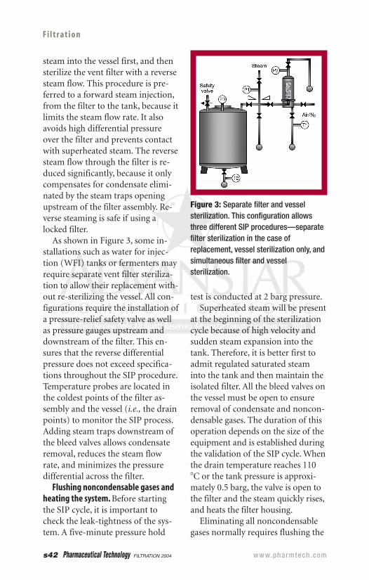
Figure 3: Separate filter and vesselsterilization. This configuration allowsthree different SIP procedures—separatefilter sterilization in the case ofreplacement, vessel sterilization only, andsimultaneous filter and vesselsterilization.
system with 10 volumes of saturatedsteam, which might take between 5and 20 min. The maximum amountof condensate is generated at the SIPstart because of the high tempera-ture difference between steam andthe heat transfer equipment. Steamtraps shut automatically once thesteam exits the drain and vent valvesand indicates that air and conden-sate have been removed. This limitsthe steam flow and allows the sys-tem to be increased and maintainedat the desired sterilization tempera-ture. Steam traps will open intermit-tently to evacuate condensate andallow replacement with fresh satu-rated steam. For manual SIP systemsthat may not include steam traps,the bleed valves must open progres-sively to avoid excessive pressure dif-ferential when steam flows throughthe filter. The bleed valves remaincracked open during the SIP cycle toeliminate condensate and adjust theflow rate across the filter.
Sterilization cycle. Once the moni-toring temperature probes locatedin the slowest heating points of thesystem (generally the vessel and fil-ter drains) indicate the set steriliza-tion temperature, the SIP plateaubegins and continues for the re-quired time period defined by thevalidation study. The pressure dif-ferential over the filter must not ex-ceed 70 mbar during the entire ster-ilization cycle to maintain the filterintegrity. Both pressure and temper-ature should be monitored to ensurethat saturated steam conditions aremet. The theoretical saturation tem-perature calculated from the actual
pressure should be in the range of6 2 8C from the actual temperature,as accepted by the European stan-dard EN 285. A current industrypractice checks for both pressureand temperature during the valida-tion and uses tighter acceptance cri-teria for the deviation (6 1 8C).Provided that routine SIP opera-tions are implemented using thesame validated SOP, only the tem-perature is monitored. This is ac-ceptable because equipment SIPprocesses generally involve numer-ous sterilization conditions.
Automatic SIP can be regulateddirectly or indirectly via a steaminlet control valve. Another possibleregulation simply involves accuratepressure regulators for the inletsteam and steam traps at the drain-ing points. During SIP, condensa-tion spontaneously draws fresh sat-urated steam and energy at thepoints where it occurs, and the ster-ilization temperature is maintainedat the set value. For manual proce-dures, the steam flow and pressuredifferential are regulated via themanual steam supply valve and thebleed valves, which remain crackedopen. Air and condensate are elimi-nated continuously through theopen bleed valves during the SIPcycle.
Venting steam, drying and cooling.Upon SIP completion, it is necessaryto release the steam pressure and re-move residual condensate from thelowest drain points of the system.This step is critical because steamcondensation can create vacuumand compromise integrity. A mole of
Pharmaceutical Technology FILTRATION 2004 s43
s44 Pharmaceutical Technology FILTRATION 2004 www.pharmtech.com
Fi l t r at i o n
saturated steam at 1218C occu-pies a volume of 15 L, whereasthe same mole of condensate onlyoccupies 18 mL. Condensationmust be compensated by sterilegas, such as air or nitrogen. Sterilecompressed gas pressurizes thesystem and completely purges thecondensate through the bleedvalves. The maintenance of steril-ity is ensured as long as the pres-sure gauges indicate a positivereading in all parts. This opera-tion also allows the cooling of theequipment and filter, which iscritical when post-SIP integritytesting has to be performed.
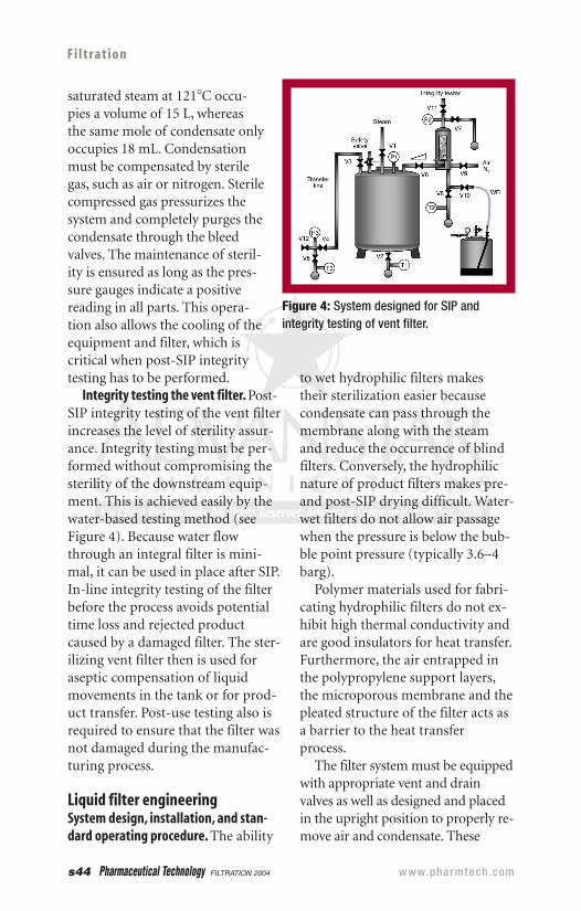
Integrity testing the vent filter. Post-SIP integrity testing of the vent filterincreases the level of sterility assur-ance. Integrity testing must be per-formed without compromising thesterility of the downstream equip-ment. This is achieved easily by thewater-based testing method (seeFigure 4). Because water flowthrough an integral filter is mini-mal, it can be used in place after SIP.In-line integrity testing of the filterbefore the process avoids potentialtime loss and rejected productcaused by a damaged filter. The ster-ilizing vent filter then is used foraseptic compensation of liquidmovements in the tank or for prod-uct transfer. Post-use testing also isrequired to ensure that the filter wasnot damaged during the manufac-turing process.
Liquid filter engineeringSystem design, installation, and stan-dard operating procedure. The ability
to wet hydrophilic filters makestheir sterilization easier becausecondensate can pass through themembrane along with the steamand reduce the occurrence of blindfilters. Conversely, the hydrophilicnature of product filters makes pre-and post-SIP drying difficult. Water-wet filters do not allow air passagewhen the pressure is below the bub-ble point pressure (typically 3.6–4barg).
Polymer materials used for fabri-cating hydrophilic filters do not ex-hibit high thermal conductivity andare good insulators for heat transfer.Furthermore, the air entrapped inthe polypropylene support layers,the microporous membrane and thepleated structure of the filter acts asa barrier to the heat transferprocess.
The filter system must be equippedwith appropriate vent and drainvalves as well as designed and placedin the upright position to properly re-move air and condensate. These
Figure 4: System designed for SIP andintegrity testing of vent filter.

Pharmaceutical Technology FILTRATION 2004 s45
valves permit a continuous steamflow during SIP and eliminate poten-tial dead flow areas.
Figure 5 depicts possible filterconfigurations. The in-line housingdesign allows the downward evacua-tion of air and condensate throughthe vertical connection to the down-stream thermostatic steam trap. TheT-type housing needs a fall onpipework for condensate drainage.If the steam is supplied from theproduct line, a thermostatic steamtrap must be installed on the top ofthe filter to evacuate air and ensurethat steam penetrates all filter as-sembly extremities. In all cases, theupstream condensate is eliminatedvia a steam trap fitted on the drainport of the housing.
Liquid filters should be sterilized inthe forward direction (separatelyfrom their associated downstreamequipment) to reduce the steam ex-pansion volume at the beginning ofthe SIP cycle. Such a procedure willlimit superheat effects and reduce thesteam flow rate over the filter. Pres-sure gauges are required upstreamand downstream of the filter to con-
trol the differential pressure. Temper-ature probes are located in the drainpoint downstream of the filter assem-bly to monitor the set temperature.The addition of steam traps anddownstream bleed valves allow con-densate removal and reduce both thesteam flow rate and the pressure dif-ferential across the filter.
Sterilization cycle. If the filter wasintegrity tested before sterilization, itmust be dried with pressurized air ornitrogen to provide a path for subse-quent steam flow-through. It cannotexceed the maximum pressure dropof 0.35 barg across the filter.
Water present in the steam line atthe beginning of the sterilizationcycle first must be purged upstreamof the filter to avoid wetting andsubsequent blocking. The bleedvalves on the filter are open to en-sure condensate and air removal.Once the temperature probe indi-cates the set sterilization tempera-ture, the SIP cycle begins and con-tinues for the required time definedduring validation. The pressure dif-ferential over the filter must not ex-ceed 350 mbar to maintain the filter
Figure 5: (Left) In-line filter housing. (Middle) T-type filter housing. (Right) T-type filterhousing equipped with a steam trap on top for air evacuation.

s46 Pharmaceutical Technology FILTRATION 2004 www.pharmtech.com
Fi l t r at i o n
integrity. Both pressureand temperature arerecorded to ensure thatsaturated steam is pres-ent in the system.
Automatic SIP is reg-ulated via the steam inletpressure reducing valveand steam traps. Manualprocedures are regulatedvia the manual steamsupply valve and down-stream bleed valves. Thebleed valves must beopened progressively toavoid excessive pressure differentialas well as eliminate air and conden-sate.
Drying, cooling, and integrity testingthe filter. After SIP, the steam supplyvalve is closed and compressed airor nitrogen is admitted to the sys-tem for cooling and drying the filter.Quick drying is obtained with boththe gas flow and the high tempera-ture of the system. As required bythe European Commission’s GoodManufacturing Practices Guide, fil-ter-integrity testing must be per-formed after sterilization but beforethe process (1). This operation canbe performed without compromis-ing the sterility of the system byusing the set-up depicted in Figure6. In most cases, water cannot be in-troduced into the system because ofsubsequent product dilution. Usingthe product as the wetting mediumenables filter integrity testing aftersteaming and avoids time loss andrejected product resulting from adamaged filter. Post-use testing alsois required to ensure that the filter
has remained integral during theentire manufacturing process.
ConclusionSteaming-in-place (SIP) is the pre-ferred method for sterilizing pro-cessing equipment, including vessels,valves, process lines, filter assem-blies, manifolds, and filling nozzles.The confirmation of a well-designedand engineered filtration system isthe ability to validate the SIP cyclesusing thermocouples and biologicalindicators. Following the design andengineering rules detailed in this ar-ticle will simplify both the validationand ongoing operation of filtrationsystems in aseptic processing.
Reference1. European Commission,“Guide to Good
Manufacturing Practice. Annex I, Manu-facture of Sterile Medicinal Products”(European Commission Enterprise Di-rectorate General, Brussels, Belgium,1997). PT
Figure 6: SIP and post-SIP integrity testing of liquidfilters.