problem 1. - weeklyjoys | me practice exams without ... vectors for the kinematic analysis of the...
TRANSCRIPT
1
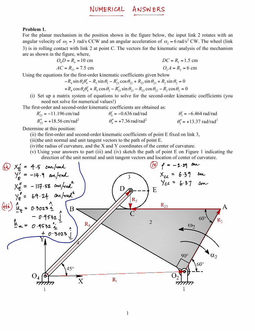
Problem 1. For the planar mechanism in the position shown in the figure below, the input link 2 rotates with an angular velocity of 2 3ω = rad/s CCW and an angular acceleration of 2 6α = rad/s2 CW. The wheel (link 3) is in rolling contact with link 2 at point C. The vectors for the kinematic analysis of the mechanism are as shown in the figure, where,
4 4 10 cmO D R= = 5 1.5 cmDC R= =
23 7.5 cmAC R= = 2 2 6 cmO A R= = Using the equations for the first-order kinematic coefficients given below
4 5 23 23 23 24 4 5 23 2sin sin cos sin i 0s nR R R R Rθ θ θθ θ θ′ ′− − +− + =
4 5 23 23 23 24 4 5 23 2cos cos sin cos o 0c sR R R R Rθ θ θ θ θ θ+ ′+ − −′ − = (i) Set up a matrix system of equations to solve for the second-order kinematic coefficients (you
need not solve for numerical values!) The first-order and second-order kinematic coefficients are obtained as:
23 11.196R′ = − cm/rad 4 0.636θ ′ = − rad/rad 3 6.464θ ′ = − rad/rad
23 18.56R′′ = + cm/rad2 4 7.36θ ′′ = + rad/rad2 23 13.37 rad/radθ′′= +
Determine at this position: (ii) the first-order and second-order kinematic coefficients of point E fixed on link 3, (iii)the unit normal and unit tangent vectors to the path of point E. (iv) the radius of curvature, and the X and Y coordinates of the center of curvature. (v) Using your answers to part (iii) and (iv) sketch the path of point E on Figure 1 indicating the
direction of the unit normal and unit tangent vectors and location of center of curvature.
2
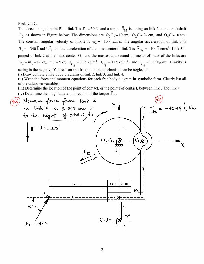
Problem 2. The force acting at point P on link 3 is PF 50 N= and a torque 12T is acting on link 2 at the crankshaft
2O as shown in Figure below. The dimensions are 32O G 10 cm,= 2O C 24 cm,= and 4O C 10 cm.= The constant angular velocity of link 2 is 2 10 k rad / s,ω = − the angular acceleration of link 3 is
23 340 k rad / s ,α = − and the acceleration of the mass center of link 3 is 2
G3A 100 i .cm/s= − Link 3 is
pinned to link 2 at the mass center 3G and the masses and second moments of mass of the links are
2 3m m 12 kg,= = 4m 5 kg,= 2
2GI 0.05 kg.m ,= 2
3GI 0.15 kg.m ,= and 2
4GI 0.03 kg.m .= Gravity is
acting in the negative Y-direction and friction in the mechanism can be neglected. (i) Draw complete free body diagrams of link 2, link 3, and link 4. (ii) Write the force and moment equations for each free body diagram in symbolic form. Clearly list all of the unknown variables. (iii) Determine the location of the point of contact, or the points of contact, between link 3 and link 4. (iv) Determine the magnitude and direction of the torque 12T .

3
Problem 3. For the planar mechanism in the position shown in the figure below (drawn half-scale), an external force
50 NP = is acting on coupler link 3 at point C and another force 30 NQ = is acting on link 5 at point E. An unknown torque 12T is acting on link 2. Gravity acts into the page and the effects of friction can be ignored. Perform a static force analysis of the mechanism using the graphical method. A suggested scale for any force polygons that you need to draw is 1 cm represents 5 N.
(i) Clearly identify the type of each link in the mechanism and draw the free body diagrams for links 2, 3, 4 and 5.
(ii) Determine the magnitude and direction of the internal reaction force between links 5 and 3. (iii) Determine the magnitude and direction of the internal reaction force between links 3 and 4 and
between links 3 and 2. (iv) Determine the magnitude and direction of the torque 12T to hold the mechanism in equilibrium.

4
Problem 4. For the mechanism in the position shown in the figure below, the input link 2 is rotating with a constant angular velocity of 2 10 rad/s=ω in the counterclockwise direction under the action of a counterclockwise input torque 2 40 N-mT = . The dimensions of the mechanism are:
2 2 2 3 2 3 25 cm.G O G A G G G B AB OG= = = = = = The free length of the spring is 10 cm, the spring stiffness is 30 N/cm,k = and the damping coefficient is 4 N-s/cm.C = The masses and second moments of mass of the links are 2 2.5 kg,m = 3 5 kg,m = 2
2 20 kg-cmGI = and 23 18 kg-cmGI = respectively. The
first-order and second-order kinematic coefficients of the mechanism are: 3 0.5 rad/rad,′ =θ
′′θ3 = 0 rad/rad2 , 23 21.65 cm/rad,R′ = and 223 6.25 cm/radR′′ = − where 23R is a vector drawn from 3G to
2.G Gravity is in the negative Y-direction, and the effects of friction can be ignored. (i) Determine the kinetic energy of the mechanism. (ii) Determine the first-order kinematic coefficient of the linear spring and of the viscous damper. (iii) Using the power equation, determine the magnitude and direction of the unknown output
torque 3T acting on link 3.