problem of cyclic hardening or softening in metals under - periodics
TRANSCRIPT
Problem of cyclic hardening or softening in metals under programmed loading 83
SCIENTIFIC PROBLEMS OF MACHINES OPERATION AND MAINTENANCE
4 (164) 2010
STANISŁAW MROZIŃSKI*, JÓZEF SZALA*
Problem of cyclic hardening or softening in metals under programmed loading
K e y w o r d s
Fatigue life, cyclic properties, cyclic softening and hardening, fatigue tests.
S ł o w a k l u c z o w e
Trwałość zmęczeniowa, cykliczne własności, cykliczne osłabienie lub umocnienie, testy zmęczeniowe.
S u m m a r y
Problem of cyclic hardening or softening in metals and their alloys has been known for over 40 years. Despite such a long period of time there is lack of the of universal models describing these processes. The basis of their valuation are experimental tests carried out under constant amplitude sinusoidal loadings. The tests can be performed under constant stress amplitude or constant strain amplitude. These conditions are not equivalent for the range of loadings, where the law of the linear relation of stress from strain is not valid. The problem of the cyclic hardening or softening in metals and their alloys becomes significantly complex in the case of variable amplitude loadings, typical for operating loadings of construction elements.
In the paper there was described the investigating of cyclic properties of three alloys: PA7 aluminium alloy strongly hardening cyclically, 30HGSA alloy steel strongly softening cyclically and C45 constructional steel which, depending on loading level, undergoes cyclic softening or cyclic hardening. The tests were carried out under programmed loadings with gradually increasing stress amplitude.
* University of Technology and Life Sciences in Bydgoszcz, al. prof. S. Kaliskiego 7, 85-796
Bydgoszcz, Poland.
Stanisław Mroziński, Józef Szala
84
1. Introduction
Fatigue in metals and their alloys is very complex process which depends on many factors and very difficult to describe [1-2]. In spite of nearly 200 years of intensive research and over 90000 publications (1995 year data according to Science Direct base) there was not developed an universal description of fatigue process so far. Fatigue calculations methods of construction elements are based on low- cycle properties of materials which are determined experimentally according to proper standards [3]. Lack of stability of cyclic properties of metals leads to serious problems in their description, usually in the form of fatigue characteristics (Wöhler, Manson – Coffin [4, 5] and Ramberg-Osgood [6] curves).
The question of cyclic properties stabilization of metals was widely analysed in the paper [7]. The earlier mentioned characteristics are determined in stress (Wöhler S-N curves) or strain approach (Manson-Coffin εa -2Νf curves and Ramberg-Osgood σ-ε curves).
Wöhler curves are used for calculations in the area of so called high- cycle fatigue (HCF), where elastic strains of the material are dominant in the area of fatigue cracks initiation, Manson-Coffin and Ramberg-Osgood curves, on the other hand, are applied in the calculations in the area of low – cycle fatigue (LCF), where plastic strains are dominant in the crack area.
As the standard of qualification of the mentioned HCF and LCF areas the plasticity limit Re is accepted, which in the case of metals is determined in the static tensile test. This limit does not correspond with the conditions of cyclic loading and is a weak criterion [8-10]. Another doubt is concerned with the assumption that under constant amplitude loadings (constant stress amplitude σa or constant total (εac) or plastic (εap) strain amplitude) there is observed stabilization of cyclic properties. As it was proved in the paper [4] cyclic properties of metals are the momentary properties – they are different in individual periods of fatigue process. The lack of stabilization is strongly visible in the case of variable amplitude loading, where every fluctuation of loading value leads to the change of cyclic properties of metals. In the case of random loadings, which are predominant under operating loadings, the change of the loading value (stress or strain) takes place “cycle after cycle”.
The recognition of the changes of cyclic properties under variable amplitude loadings which are located in HCF and LCF area is the main cognitive and utilitarian aim of this paper. An additional aims are: − to prove the weakness of accepting plasticity limit Re as the criterion of the
loading qualification to HCF and LCF area, − fatigue life determination under programmed loading, − comparative analysis of the chosen mechanical parameters determined under
monotonic and cyclic loadings.
Problem of cyclic hardening or softening in metals under programmed loading 85
2. Test description
The valuation of cyclic properties of the tested metals was based on stress- strain hysteresis loop parameters recorded during the tests from the first till the last cycle both under constant amplitude and programmed loading.
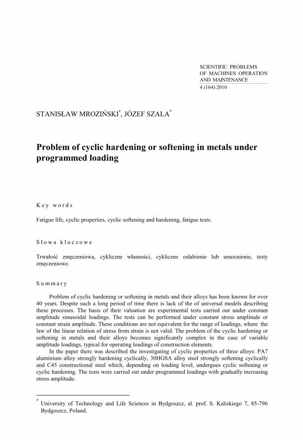
Program of the tests included five – step loading with the period of program including ten cycles (Fig. 1a). Tests were performed with the use of specimens made of C45 steel, 30HGSA steel and PA7 aluminium alloy (Fig. 1b). These materials differed significantly in their cyclic and monotonic properties.
a) b)
0
100
200
300
400
500
600
700
0
σ, MPa
σa1 σa2
σa3 σa4
σa5 ReH
φ 10
h8
200
φ 25
15
A 0,03 A
R40 R40
1x45o
Ra0,32
1x45o
Fig. 1. Test description: a) loading program, b) specimen for the fatigue tests Rys. 1. Opis badań: a) program obciążenia, b) próbki do badań zmęczeniowych
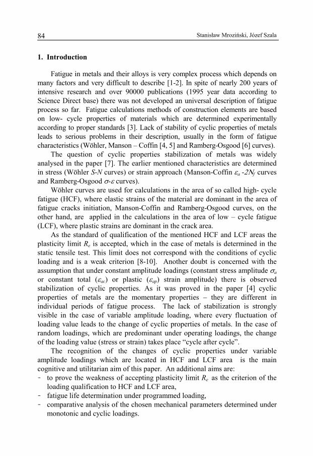
Diagrams of static tensile tests of the specimens made of the accepted
materials were presented in Fig. 2 and strength parameters determined on their base in Table 1.
0
200
400
600
800
1000
1200
0 5 10 15 20 25
2
1
3
ε, %
σ, MPa
1- C45 steel 2- 30HGSA steel 3- PA7 alloy
Material Parameter C45
steel 30HGSA
steel PA7 alloy
ReH, MPa 446,3 936,7 321,7 Rm, MPa 713,3 1030 514,7 E, MPa 215000 207000 75000 A5, % 22 9,5 16
Table 1. Static tests results
Fig. 2. Diagrams of static tensile tests Rys. 2. Wykresy rozciągania próbek
Material Parameter C45
steel 30HGSA
steel PA7 alloy
ReH, MPa 446.3 936.7 321.7 Rm, MPa 713.3 1030 514.7 E, MPa 215000 207000 75000 A5, % 22 9,5 16
Table 1. Static tests results Tabela 1. Wyniki prób statycznych
Stanisław Mroziński, Józef Szala
86
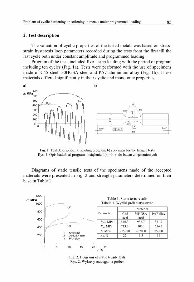
Constant amplitude loadings were performed on five levels of total strain εac = const. On each level there were performed three fatigue tests. Hysteresis loops in respective periods of fatigue process were recorded. As the criterion of the fatigue test ending the occurig of deformation of hysteresis loop arm in the half – cycle of squeezing (occuring of the twist) was accepted. Sampling time of the loading force and strain signals was equal 0.025 s which at frequency of loading f = 0.2 Hz allowed for description of hysteresis loop with 200 points. Tests parameters under constant amplitude loadings are presented in Table 2.
Table 2. Parameters of constant amplitude loadings Tabela 2. Parametry obciążeń stałoamplitudowych
Parameters Scheme of the program C45 steel,
30HGSA steel PA7 alloy
ε, %
ε ac
t
εac = 0.35% εac = 0.5% εac = 0.8% εac = 1.0% εac = 2.0%
f = 0.2 Hz
εac = 0.50% εac = 0.65% εac = 0.80% εac = 1.0% εac = 1.5% f = 0.2 Hz
Controlling parameter during the tests under programmed loading was the force
converted into stress. The rate of the stress growth was equal 50 MPa·s-1. For each sequence of programmed loading three fatigue tests were performed, just like under constant amplitude loading. During the tests under programmed loadings momentary values of the loading force and strain for the whole chosen loading blocks with the volume of no = 10 cycles were recorded. Program of loadings was carried out by the way of repeating the program blocks until failure. Values of the stress amplitudes on individual steps of tested materials were given in Table 3.
Table 3. Parameters of programmed loadings
Tabela 3. Parametry obciążeń programowanych
Stress amplitude on the step σai Material σa1 σa2 σa3 σa4 σa5 σa6
30HGSAsteel 510 570 630 690 750 810 C45 steel 200 260 320 380 440 - PA7 alloy 325 350 375 425 450 475
3. Tests results
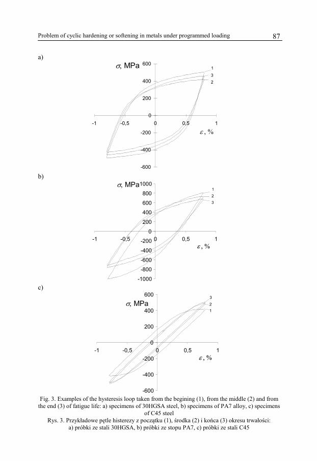
The examples of hysteresis loops for one strain amplitude level εac = 0,8% were shown in Fig. 3. To make the diagrams more transparent there were drawn only three characteristic loops for each material: 1 - for the first cycle, 2 - for the cycle from the half - life of the specimen and 3 - for the cycle corresponding with the total life.
Problem of cyclic hardening or softening in metals under programmed loading 87
a)
-600
-400
-200
0
200
400
600
-1 -0,5 0 0,5 1
ε , %
σ, MPa 1
23
b)
-1000
-800
-600
-400
-200
0
200
400
600
800
1000
-1 -0,5 0 0,5 1
1
32
ε , %
σ, MPa
c)
-600
-400
-200
0
200
400
600
-1 -0,5 0 0,5 1ε , %
3
12σ, MPa
Fig. 3. Examples of the hysteresis loop taken from the begining (1), from the middle (2) and from
the end (3) of fatigue life: a) specimens of 30HGSA steel, b) specimens of PA7 alloy, c) specimens of C45 steel
Rys. 3. Przykładowe pętle histerezy z początku (1), środka (2) i końca (3) okresu trwałości: a) próbki ze stali 30HGSA, b) próbki ze stopu PA7, c) próbki ze stali C45
Stanisław Mroziński, Józef Szala
88
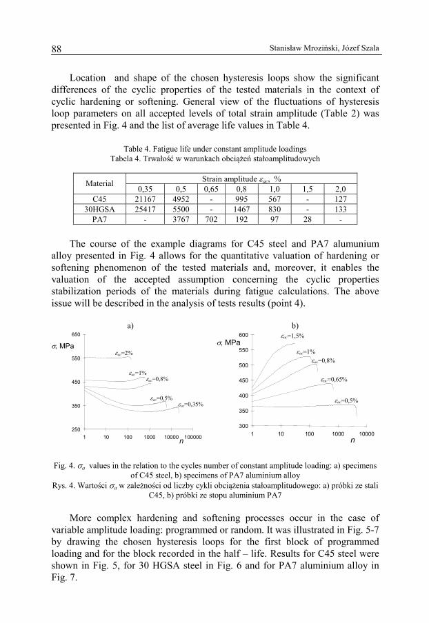
Location and shape of the chosen hysteresis loops show the significant differences of the cyclic properties of the tested materials in the context of cyclic hardening or softening. General view of the fluctuations of hysteresis loop parameters on all accepted levels of total strain amplitude (Table 2) was presented in Fig. 4 and the list of average life values in Table 4.
Table 4. Fatigue life under constant amplitude loadings Tabela 4. Trwałość w warunkach obciążeń stałoamplitudowych
Strain amplitude εac, % Material
0,35 0,5 0,65 0,8 1,0 1,5 2,0 C45 21167 4952 - 995 567 - 127
30HGSA 25417 5500 - 1467 830 - 133 PA7 - 3767 702 192 97 28 -
The course of the example diagrams for C45 steel and PA7 alumunium
alloy presented in Fig. 4 allows for the quantitative valuation of hardening or softening phenomenon of the tested materials and, moreover, it enables the valuation of the accepted assumption concerning the cyclic properties stabilization periods of the materials during fatigue calculations. The above issue will be described in the analysis of tests results (point 4).
a) b)
250
350
450
550
650
1 10 100 1000 10000 100000n
σ, MPa εac=2%
εac=1% εac=0,8%
εac=0,5% εac=0,35%
300
350
400
450
500
550
600
1 10 100 1000 10000
σ, MPa
n
εac=1,5%
εac=1%εac=0,8%
εac=0,65%
εac=0,5%
Fig. 4. σa values in the relation to the cycles number of constant amplitude loading: a) specimens of C45 steel, b) specimens of PA7 aluminium alloy
Rys. 4. Wartości σa w zależności od liczby cykli obciążenia stałoamplitudowego: a) próbki ze stali C45, b) próbki ze stopu aluminium PA7
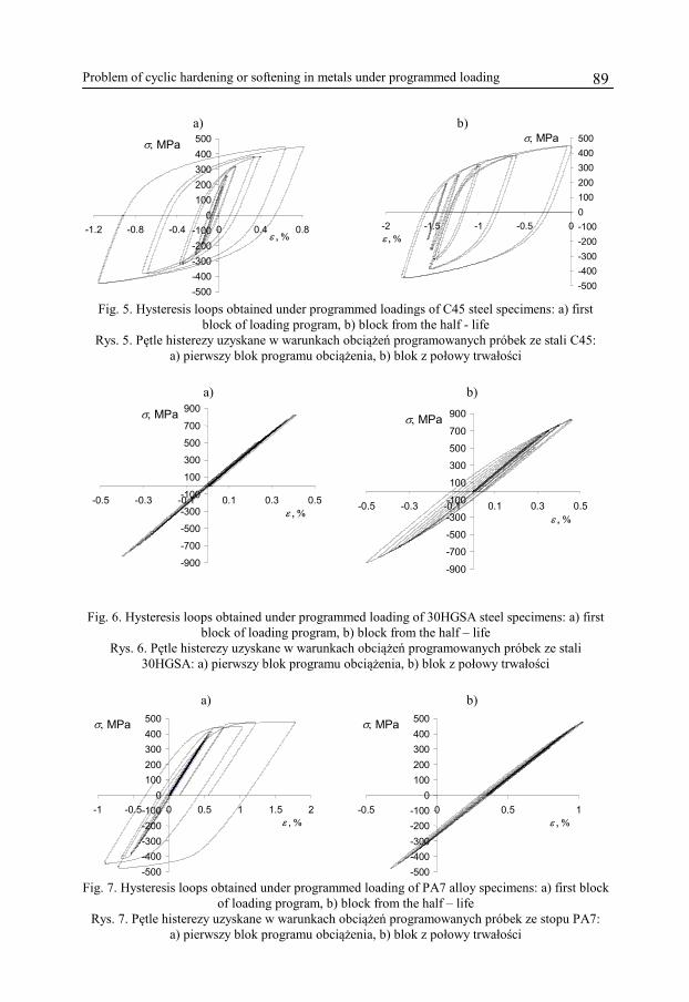
More complex hardening and softening processes occur in the case of
variable amplitude loading: programmed or random. It was illustrated in Fig. 5-7 by drawing the chosen hysteresis loops for the first block of programmed loading and for the block recorded in the half – life. Results for C45 steel were shown in Fig. 5, for 30 HGSA steel in Fig. 6 and for PA7 aluminium alloy in Fig. 7.
Problem of cyclic hardening or softening in metals under programmed loading 89
a) b)
-500 -400 -300 -200 -100
0 100 200 300 400 500
-1.2 -0.8 -0.4 0 0.4 0.8
σ, MPa
ε , %
-500 -400 -300 -200 -100 0 100 200 300 400 500
-2 -1.5 -1 -0.5 0 ε , %
σ, MPa
Fig. 5. Hysteresis loops obtained under programmed loadings of C45 steel specimens: a) first
block of loading program, b) block from the half - life Rys. 5. Pętle histerezy uzyskane w warunkach obciążeń programowanych próbek ze stali C45:
a) pierwszy blok programu obciążenia, b) blok z połowy trwałości
a) b)
-900 -700 -500 -300 -100 100 300 500 700 900
-0.5 -0.3 -0.1 0.1 0.3 0.5
σ, MPa
ε , %
-900
-700
-500
-300
-100
100
300
500
700
900
-0.5 -0.3 -0.1 0.1 0.3 0.5
σ, MPa
ε , %
Fig. 6. Hysteresis loops obtained under programmed loading of 30HGSA steel specimens: a) first block of loading program, b) block from the half – life
Rys. 6. Pętle histerezy uzyskane w warunkach obciążeń programowanych próbek ze stali 30HGSA: a) pierwszy blok programu obciążenia, b) blok z połowy trwałości
a) b)
-500 -400 -300 -200 -100
0 100 200 300 400 500
-1 -0.5 0 0.5 1 1.5 2
σ, MPa
ε , %
-500-400-300-200-100
0100200300400500
-0.5 0 0.5 1 ε , %
σ, MPa
Fig. 7. Hysteresis loops obtained under programmed loading of PA7 alloy specimens: a) first block
of loading program, b) block from the half – life Rys. 7. Pętle histerezy uzyskane w warunkach obciążeń programowanych próbek ze stopu PA7:
a) pierwszy blok programu obciążenia, b) blok z połowy trwałości
Stanisław Mroziński, Józef Szala
90
Basing on the diagrams presented in Fig. 5-7, it can be found that under programmed loading with the force (converted into stress) as controlled parameter there occurs the cyclic creeping phenomenon, which significantly, negatively influences the analysis of tests results. It is visible in the case of C45 steel (Fig. 5) and PA7 aluminium alloy (Fig. 7). In considered tests fatigue life was also determined. These data were presented in Table 5.
Table 5. Fatigue life under programmed loadings
Tabela 5. Trwałość zmęczeniowa w badaniach programowanych
Fatigue life N Material Number of blocks Number of cycles
Stal C45 98 979 Stal 30HGSA 31 305
Stop PA7 139 1388 Fatigue life results given in Table 5 can be used in experimental
verification of the calculation methods. Because of the limited volume of this paper these methods are not described here.
4. Analysis of obtained results
4.1. Constant amplitude loadings
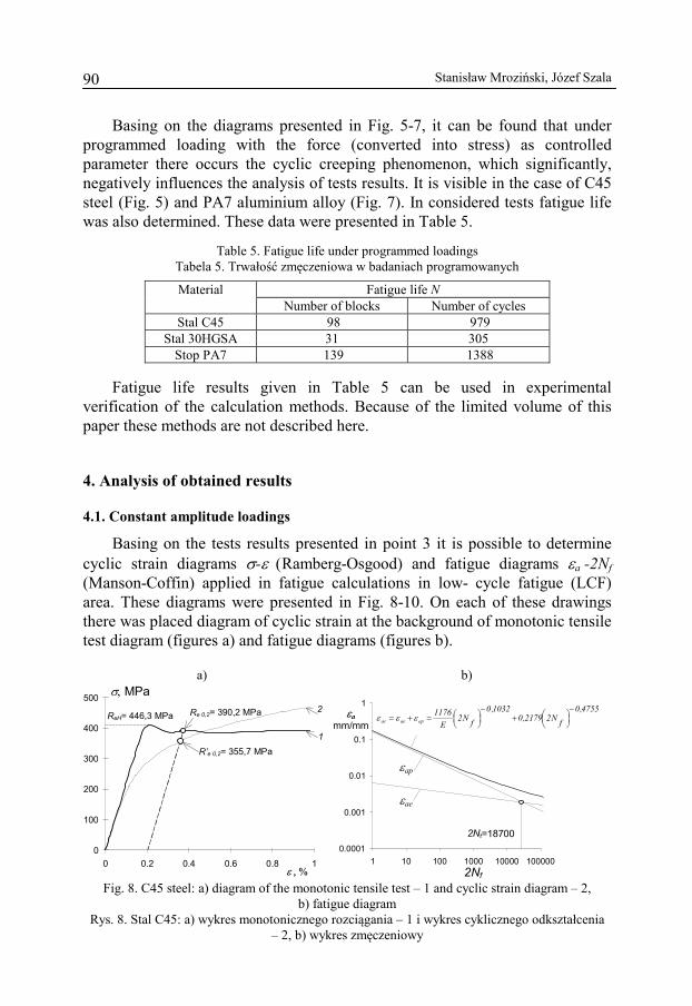
Basing on the tests results presented in point 3 it is possible to determine cyclic strain diagrams σ-ε (Ramberg-Osgood) and fatigue diagrams εa -2Nf (Manson-Coffin) applied in fatigue calculations in low- cycle fatigue (LCF) area. These diagrams were presented in Fig. 8-10. On each of these drawings there was placed diagram of cyclic strain at the background of monotonic tensile test diagram (figures a) and fatigue diagrams (figures b).
a) b)
0
100
200
300
400
500
0 0.2 0.4 0.6 0.8 1
Re 0,2= 390,2 MPa
R’e 0,2= 355,7 MPa
σ, MPa
ε , %
2
1
ReH= 446,3 MPa
0.0001
0.001
0.01
0.1
1
1 10 100 1000 10000 100000
4755,0fN22179,0
1032,0fN2
E1176
apaeac
−⎟⎠⎞⎜
⎝⎛+
−⎟⎠⎞⎜
⎝⎛=+= εεε
εap
εae
2Nt=18700
2Nf
εa mm/mm
Fig. 8. C45 steel: a) diagram of the monotonic tensile test – 1 and cyclic strain diagram – 2,
b) fatigue diagram Rys. 8. Stal C45: a) wykres monotonicznego rozciągania – 1 i wykres cyklicznego odkształcenia
– 2, b) wykres zmęczeniowy
Problem of cyclic hardening or softening in metals under programmed loading 91
a) b)
0 200 400 600 800
1000 1200
0 0.2 0.4 0.6 0.8 1
σ, MPa
ε , %
Re 0,2= 993,2 MPa
R’e 0,2= 690,0 MPa
1
2
0.001
0.01
0.1
1
1 10 100 1000 10000 100000
6568,0fN26525,0
1014,0fN2
E1852
apaeac
−⎟⎠⎞⎜
⎝⎛+
−⎟⎠⎞⎜
⎝⎛=+= εεεεa
mm/mm
εap
εae
2Nt=2372
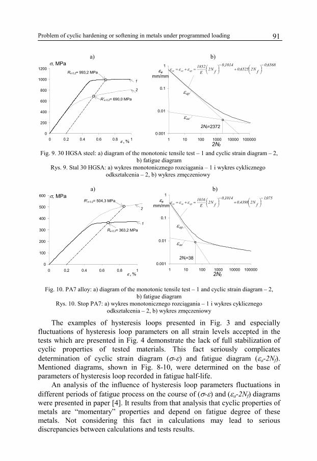
2Nf Fig. 9. 30 HGSA steel: a) diagram of the monotonic tensile test – 1 and cyclic strain diagram – 2,
b) fatigue diagram Rys. 9. Stal 30 HGSA: a) wykres monotonicznego rozciągania – 1 i wykres cyklicznego
odkształcenia – 2, b) wykres zmęczeniowy
a) b)
0
100
200
300
400
500
600
0 0.2 0.4 0.6 0.8 1
σ, MPa
ε , %
Re 0,2= 363,2 MPa
R’e 0,2= 504,3 MPa 2
1
0.001
0.01
0.1
1
1 10 100 1000 10000 100000 2Nf
2Nt=38
εae
εap
εa mm/mm
075,1fN24398,0
1014,0fN2
E1016
apaeac
−⎟⎠⎞⎜
⎝⎛+
−⎟⎠⎞⎜
⎝⎛=+= εεε
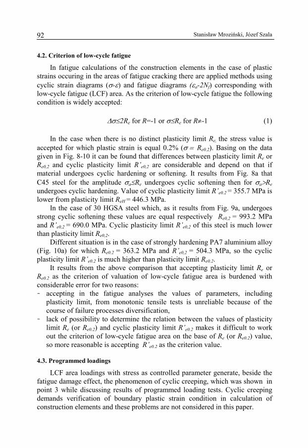
Fig. 10. PA7 alloy: a) diagram of the monotonic tensile test – 1 and cyclic strain diagram – 2,
b) fatigue diagram Rys. 10. Stop PA7: a) wykres monotonicznego rozciągania – 1 i wykres cyklicznego
odkształcenia – 2, b) wykres zmęczeniowy
The examples of hysteresis loops presented in Fig. 3 and especially fluctuations of hysteresis loop parameters on all strain levels accepted in the tests which are presented in Fig. 4 demonstrate the lack of full stabilization of cyclic properties of tested materials. This fact seriously complicates determination of cyclic strain diagram (σ-ε) and fatigue diagram (εa-2Nf). Mentioned diagrams, shown in Fig. 8-10, were determined on the base of parameters of hysteresis loop recorded in fatigue half-life.
An analysis of the influence of hysteresis loop parameters fluctuations in different periods of fatigue process on the course of (σ-ε) and (εa-2Nf) diagrams were presented in paper [4]. It results from that analysis that cyclic properties of metals are “momentary” properties and depend on fatigue degree of these metals. Not considering this fact in calculations may lead to serious discrepancies between calculations and tests results.
Stanisław Mroziński, Józef Szala
92
4.2. Criterion of low-cycle fatigue
In fatigue calculations of the construction elements in the case of plastic strains occuring in the areas of fatigue cracking there are applied methods using cyclic strain diagrams (σ-ε) and fatigue diagrams (εa-2Nf) corresponding with low-cycle fatigue (LCF) area. As the criterion of low-cycle fatigue the following condition is widely accepted:
Δσ≤2Re for R=-1 or σ≤Re for R≠-1 (1)
In the case when there is no distinct plasticity limit Re, the stress value is
accepted for which plastic strain is equal 0.2% (σ = Re0.2). Basing on the data given in Fig. 8-10 it can be found that differences between plasticity limit Re or Re0,2 and cyclic plasticity limit R’e0,2 are considerable and depend on that if material undergoes cyclic hardening or softening. It results from Fig. 8a that C45 steel for the amplitude σa≤Re undergoes cyclic softening then for σa>Re undergoes cyclic hardening. Value of cyclic plasticity limit R’e0.2 = 355.7 MPa is lower from plasticity limit ReH = 446.3 MPa.
In the case of 30 HGSA steel which, as it results from Fig. 9a, undergoes strong cyclic softening these values are equal respectively Re0,2 = 993.2 MPa and R’e0,2 = 690.0 MPa. Cyclic plasticity limit R’e0,2 of this steel is much lower than plasticity limit Re0,2.
Different situation is in the case of strongly hardening PA7 aluminium alloy (Fig. 10a) for which Re0.2 = 363.2 MPa and R’e0,2 = 504.3 MPa, so the cyclic plasticity limit R’e0.2 is much higher than plasticity limit Re0.2.
It results from the above comparison that accepting plasticity limit Re or Re0.2 as the criterion of valuation of low-cycle fatigue area is burdened with considerable error for two reasons: − accepting in the fatigue analyses the values of parameters, including
plasticity limit, from monotonic tensile tests is unreliable because of the course of failure processes diversification,
− lack of possibility to determine the relation between the values of plasticity limit Re (or Re0.2) and cyclic plasticity limit R’e0.2 makes it difficult to work out the criterion of low-cycle fatigue area on the base of Re (or Re0.2) value, so more reasonable is accepting R’e0.2 as the criterion value.
4.3. Programmed loadings
LCF area loadings with stress as controlled parameter generate, beside the fatigue damage effect, the phenomenon of cyclic creeping, which was shown in point 3 while discussing results of programmed loading tests. Cyclic creeping demands verification of boundary plastic strain condition in calculation of construction elements and these problems are not considered in this paper.
Problem of cyclic hardening or softening in metals under programmed loading 93
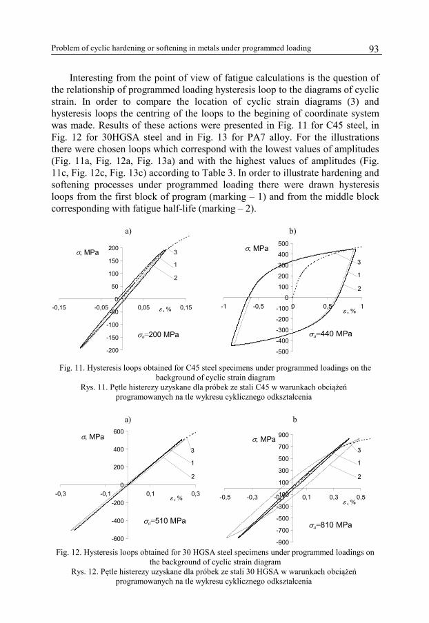
Interesting from the point of view of fatigue calculations is the question of the relationship of programmed loading hysteresis loop to the diagrams of cyclic strain. In order to compare the location of cyclic strain diagrams (3) and hysteresis loops the centring of the loops to the begining of coordinate system was made. Results of these actions were presented in Fig. 11 for C45 steel, in Fig. 12 for 30HGSA steel and in Fig. 13 for PA7 alloy. For the illustrations there were chosen loops which correspond with the lowest values of amplitudes (Fig. 11a, Fig. 12a, Fig. 13a) and with the highest values of amplitudes (Fig. 11c, Fig. 12c, Fig. 13c) according to Table 3. In order to illustrate hardening and softening processes under programmed loading there were drawn hysteresis loops from the first block of program (marking – 1) and from the middle block corresponding with fatigue half-life (marking – 2).
a) b)
-200
-150
-100
-50
0
50
100
150
200
-0,15 -0,05 0,05 0,15
σa=200 MPa
σ, MPa
ε , %
1 2
3
-500
-400
-300
-200
-100
0
100
200
300
400
500
-1 -0,5 0 0,5 1
σa=440 MPa
ε , %
σ, MPa
1 2
3
Fig. 11. Hysteresis loops obtained for C45 steel specimens under programmed loadings on the background of cyclic strain diagram
Rys. 11. Pętle histerezy uzyskane dla próbek ze stali C45 w warunkach obciążeń programowanych na tle wykresu cyklicznego odkształcenia
a) b
-600
-400
-200
0
200
400
600
-0,3 -0,1 0,1 0,3
σa=510 MPa
σ, MPa
1
2
3
ε , %
-900
-700
-500
-300
-100
100
300
500
700
900
-0,5 -0,3 -0,1 0,1 0,3 0,5
σa=810 MPa
ε , %
σ, MPa
1 2
3
Fig. 12. Hysteresis loops obtained for 30 HGSA steel specimens under programmed loadings on
the background of cyclic strain diagram Rys. 12. Pętle histerezy uzyskane dla próbek ze stali 30 HGSA w warunkach obciążeń
programowanych na tle wykresu cyklicznego odkształcenia
Stanisław Mroziński, Józef Szala
94
a) b)
-500 -400 -300 -200 -100
0 100 200 300 400 500
-0,8 -0,4 0 0,4 0,8
σa=425 MPa
σ, MPa
ε , %
1
2
3
-500
-400
-300
-200
-100
0
100
200
300
400
500
-1,5 -1 -0,5 0 0,5 1 1,5
σa=440 MPa
σ, MPa
ε , %
1 2
3
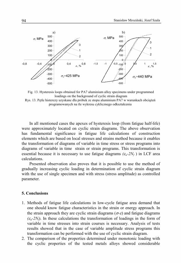
Fig. 13. Hysteresis loops obtained for PA7 aluminium alloy specimens under programmed loadings on the background of cyclic strain diagram
Rys. 13. Pętle histerezy uzyskane dla próbek ze stopu aluminium PA7 w warunkach obciążeń programowanych na tle wykresu cyklicznego odkształcenia
In all mentioned cases the apexes of hysteresis loop (from fatigue half-life)
were approximately located on cyclic strain diagrams. The above observation has fundamental significance in fatigue life calculations of construction elements which are based on local stresses and strains method because it enables the transformation of diagrams of variable in time stress or stress programs into diagrams of variable in time strain or strain programs. This transformation is essential because it is necessary to use fatigue diagrams (εa-2Nf ) in LCF area calculations.
Presented observation also proves that it is possible to use the method of gradually increasing cyclic loading in determination of cyclic strain diagram with the use of single specimen and with stress (stress amplitude) as controlled parameter.
5. Conclusions
1. Methods of fatigue life calculations in low-cycle fatigue area demand that one should know fatigue characteristics in the strain or energy approach. In the strain approach they are cyclic strain diagrams (σ-ε) and fatigue diagrams (εa-2Nf). In these calculations the transformation of loadings in the form of variable in time stresses into strain courses is necessary. Analysis of tests results showed that in the case of variable amplitude stress programs this transformation can be performed with the use of cyclic strain diagram.
2. The comparison of the properties determined under monotonic loading with the cyclic properties of the tested metals alloys showed considerable
Problem of cyclic hardening or softening in metals under programmed loading 95
differences of these properties which were generated by cyclic hardening (PA7 aluminium alloy) or softening (30HGSA steel). In the case of C45 steel after initial softening there took place considerable cyclic hardening of the material.
3. The basic parameter, important from the point of view of fatigue calculations, is plasticity limit and elasticity module. Comparison of tensile tests diagrams and cyclic strain diagrams showed the high agreement of elasticity module and essential differences in the values of plasticity limit and cyclic plasticity limit.
4. Analysis of the tests results showed that plasticity limit of metals Re used for determination of low-cycle fatigue area is an approximate criterion, which do not correspond with the process of failure in metals under cyclic loading.
5. The suitable parameters accepted as the valuation criterion of low-cycle fatigue area are these which are related to the cyclic properties of metals, for example cyclic plasticity limit determined from cyclic strain diagram which is necessary in fatigue calculations of construction elements under loadings generating local plastic strains.
The paper was presented at the VI International Symposium of Materials
and Constructions Failure Mechanics in Augustów in 2011 and was published in Polish language in “Acta Mechanica et Automatica” guarterly vol. 5 no. 3 (2011), publication of Faculty of Mechnical Engineering of Bialystok Univeristy of Technology.
This article was created on the base of tests results funded by MNiSzW in the framework of the project NN 503222139.
References
[1] Kocańda S., Zmęczeniowe pękanie metali. WNT, Warszawa 1985. [2] Kocańda S., Kocańda A., Niskocyklowa wytrzymałość zmęczeniowa metali. PWN, Warszawa
1989. [3] Kocańda S., Szala J., Podstawy obliczeń zmęczeniowych. PWN, Warszawa 1997. [4] Manson S.S., Behaviour of materials under conditions of thermal stress. NACA TN – 2933,
1953. [5] Coffin L.F., A study of the effects of cyclic thermal stresses on a ductile metal. Trans.
ASME 76, 1954, 931-950. [6] Ramberg W., Osgood W.R., Description of stress-strain curves by three parameters. NACA,
Tech. Note 402, 1943. [7] Mroziński S., Stabilizacja własności cyklicznych metali i jej wpływ na trwałość
zmęczeniową. Wydawnictwo Uczelniane Uniwersytetu Technologiczno-Przyrodniczego w Bydgoszczy, Rozprawy Nr 128, 2008.
[8] Duyi Y., Zhenlin W., A new approach to low cycle fatigue damage based on exhaustion of static toughness and dissipation of cyclic plastic strain energy during fatigue. International Journal of Fatigue 23, 2001, 679-687.
Stanisław Mroziński, Józef Szala
96
[9] Duyi Y., Zhenlin W., Change characteristics of static mechanical property parameters and dislocation structures of 45# medium carbon structural steel during fatigue failure process. Materials Science & Engineering A297, 2001, 54-61.
[10] Szala J., Ligaj B., Szala G., Wytrzymałość wstępnie cyklicznie obciążonych próbek ze stopu aluminium D16CzATW. XIX Sympozjum Zmęczenie i Mechanika Pękania, Pieczyska k. Bydgoszczy, 2002, 373-382.
[11] Procedury FITNET (Fitness - for - service NETwork). Zagadnienie cyklicznego umocnienia lub osłabienia metali w warunkach obciążenia
programowanego
S t r e s z c z e n i e
Zjawisko cyklicznego umocnienia lub osłabienia metali i ich stopów jest znane od ponad 40 lat. Mimo tak długiego okresu badań brak jest ogólnego opisu uniwersalnych modeli tych zjawisk. Podstawą w ich ocenie są badania doświadczalne prowadzone w warunkach obciążeń sinusoidalnych stałoamplitudowych. Wyróżnia się badania ze stałą amplitudą naprężenia lub stałą amplitudą odkształcenia. Warunki te nie są równoważne w zakresie obciążeń, w których nie obowiązuje prawo liniowej zależności naprężenia od odkształcenia. Zagadnienie cyklicznego umocnienia lub osłabienia metali oraz ich stopów istotnie komplikuje się w przypadku zmiennoamplitudowych obciążeń, które są charakterystyczne dla obciążeń eksploatacyjnych elementów konstrukcyjnych.
W pracy opisano badania własności cyklicznych trzech stopów metali: stopu aluminium PA7 silnie umacniającego się cyklicznie, stali stopowej 30HGSA- podlegającej silnemu cyklicznemu osłabieniu oraz stali konstrukcyjnej C45, która w zależności od poziomu obciążenia ulega cyklicznemu osłabieniu lub cyklicznemu umocnieniu. Badania przeprowadzono w warunkach programowanych obciążeń ze stopniowo rosnącą amplitudą naprężenia.