process efficiency optimisation of cascade lng process
TRANSCRIPT

Department of Chemical Engineering
Faculty of Science and Engineering
Process Efficiency Optimisation of Cascade LNG Process
Nazreen Begum Najibullah Khan
This thesis is presented for the Degree of
Doctor of Philosophy
of
Curtin University
July 2018
i
Declaration
To the best of my knowledge and belief this thesis contains no material previously published
by any other person except where due acknowledgement has been made.
This thesis contains no material which has been accepted for the award of any other degree
or diploma in any university.
Your signature :
Date :
16 July 2018

ii
Copyright
I acknowledged that I have obtained the approval from the copyright owners to use any of
my published work such as journal and conference papers for this thesis where the
ownership is held by Elsevier and CSIRO Publishing. The permission to utilise the published
material by the author has been stated in the copyright link below:
Elsevier: https://www.elsevier.com/about/our-business/policies/copyright/personal-use
CSIRO Publishing: http://www.publish.csiro.au/journals/copyright
Your signature :
Date :
16 July 2018

iii
Author’s Biography
Nazreen Begum Najibullah Khan completed her Bachelor of Chemical Engineering (Hons)
from Universiti Teknologi Mara, Shah Alam (Malaysia) in 2007. She has worked for Shell
Global Solutions Malaysia from 2007-2010 as a Process Engineer in the LNG and Gas
department. She also worked as a contract-lecturer at Universiti Teknologi Mara,
Terengganu for 5 months (June-Oct 2012). In September 2013, she commenced her PhD
research in natural gas processing at Curtin University. She received a scholarship from the
Ministry Higher of Education Malaysia and Universiti Malaysia Pahang, Malaysia to pursue
her postgraduate study.
Journal publications (published):
1. Najibullah Khan, N.B., A. Barifcani, M. Tade, and V. Pareek, A case study:
Application of energy and exergy analysis for enhancing the process efficiency of a
three stage propane pre-cooling cycle of the cascade LNG process.
Journal of Natural Gas Science and Engineering, 2016. 29: p. 125-133.
DOI (http://dx.doi.org/10.1016/j.jngse.2015.12.034)
2. Najibullah Khan, N.B., A. Barifcani, M. Tade, and V. Pareek, Exergy analysis of an
ethylene refrigeration cycle integrated with a NGL recovery process for
a large LNG train. The APPEA Journal, 2016. 56(2): p. 606-606.
DOI (https://doi.org/10.1071/AJ15112)
Manuscripts in preparation
1. Najibullah Khan, N.B., A. Barifcani, M. Tade, and V. Pareek, Effect of deethaniser
(De-C2) column pressure on the process efficiency of an integrated LNG/NGL Plant,
to be submitted to another journal.
2. Najibullah Khan, N.B., A. Barifcani, M. Tade, and V. Pareek, A review of LNG
processes that are suitable for a single large-scale LNG train, to be submitted to
another journal.
Conferences:
Oral presentation:
1. N.B. Najibullah Khan, A. Barifcani, M. Tade, V. Pareek, Energy optimization of
cascade refrigeration systems for Liquefied Natural Gas (LNG) plant, in: Chemeca
2014: Processing excellence; Powering our future, 2014, pp. 260.

iv
Poster presentation:
1. N.B. Najibullah Khan, A. Barifcani, M. Tade, V. Pareek, Exergy analysis of an
ethylene refrigeration cycle integrated with an NGL recovery process for a large
LNG train, in: APPEA 2016 56th Conference and Exhibition, mediadynamics,
Brisbane, Australia, 2016, pp. 1-5.

v
Dedication
I would like to dedicate my thesis to my dear late father and uncle. My mother for her
continuous prayers and help
To my husband and my daughter for their greatest help, advice, support and patience
To my siblings, family and friends for their prayers and encouragement

vi
Table of Contents
Declaration ................................................................................................................................ i
Copyright ................................................................................................................................. ii
Author’s Biography ................................................................................................................ iii
Dedication ................................................................................................................................ v
Table of Contents .................................................................................................................... vi
Acknowledgements ................................................................................................................. xi
Abstract ................................................................................................................................. xiii
List of Figures ........................................................................................................................ xv
List of Tables ...................................................................................................................... xviii
Nomenclature ......................................................................................................................... xx
Chapter 1 Introduction .......................................................................................................... 1
1.1 LNG – future energy fuel ......................................................................................... 1
1.2 Overview of LNG plant processes ........................................................................... 4
1.3 What is LNG process optimisation? ........................................................................ 6
1.4 Why do LNG plants need to be optimised? ............................................................. 7
1.5 Progress in LNG plant optimisation ......................................................................... 8
1.6 Scope and objectives of this study ......................................................................... 13
1.7 Contributions of this thesis .................................................................................... 14
1.8 Thesis outline ......................................................................................................... 15
........................................................................................................................................... 17
Chapter 2 LNG refrigeration processes and thermodynamic analysis................................ 18
2.1 Introduction ............................................................................................................ 18
2.2 LNG processes for a single large-scale LNG train ................................................ 18
2.2.1 Propane pre-cooled mixed refrigerant (C3MR) process ................................ 18
2.2.2 Split MR process ............................................................................................ 20
2.2.3 AP-XTM process ............................................................................................. 21
2.2.4 Dual mixed refrigerant (DMR) process ......................................................... 23
2.2.5 Parallel mixed refrigerant (PMR) process ...................................................... 24

vii
2.2.6 LiquefinTM process ......................................................................................... 25
2.2.7 Mixed fluid cascade (MFC) process .............................................................. 26
2.2.8 Phillips optimised cascade (POC) LNG process ............................................ 28
2.3 Why cascade LNG process? .................................................................................. 33
2.4 Why 5 MTPA production train? ............................................................................ 35
2.5 Fundamentals principles of LNG processes ........................................................... 36
2.5.1 First and second laws of thermodynamics ..................................................... 36
2.5.2 Heat exchange terminologies of a refrigeration system ................................. 40
2.5.2.1 Superheat .................................................................................................... 40
2.5.2.2 Sub-cooling ................................................................................................ 40
2.5.2.3 Sensible heat and latent heat ...................................................................... 41
2.6 Thermodynamics expansion processes .................................................................. 41
2.6.1 Joule Thomson expansion process ................................................................. 42
2.6.2 Brayton expansion process ............................................................................. 43
2.6.3 Claude expansion process .............................................................................. 43
2.7 Refrigeration systems ............................................................................................. 44
2.7.1 Types of the compression cycle ..................................................................... 44
2.7.1.1 Ideal compression cycle ............................................................................. 45
2.7.1.2 Non-ideal compression cycle ..................................................................... 47
2.7.2 Multistage compression and expansion ......................................................... 49
2.7.3 Refrigeration cycle performance .................................................................... 57
2.7.4 Selection criteria for a refrigerant .................................................................. 58
2.7.5 LNG higher heating value (HHV).................................................................. 63
2.8 Energy and exergy analyses ................................................................................... 64
2.8.1 Background of energy and exergy analyses ................................................... 64
2.8.2 Benefits of using energy and exergy analyses ............................................... 69
2.8.3 Application of energy and exergy analyses in LNG processes ...................... 69
2.9 Optimisation of LNG processes ............................................................................. 70
2.9.1 Pre-cooling cycle optimisation ....................................................................... 70

viii
2.9.2 Gaps in the optimisation of the pre-cooling cycle ......................................... 73
2.9.3 Integrated LNG/NGL processing plant optimisation ..................................... 75
2.9.4 NGL process optimisation ............................................................................. 78
2.9.5 Gaps in the optimisation of the integrated LNG/NGL plants and NGL
processes 79
Chapter 3 Process modelling and simulation of Cascade LNG process ............................. 82
3.1 Introduction ............................................................................................................ 82
3.2 Simulation basis and modelling assumptions ........................................................ 82
3.3 Process simulation constraints ............................................................................... 84
3.4 Cascade LNG process simulation description........................................................ 84
3.5 Optimisation framework of Cascade LNG process ............................................... 93
3.6 Simulation model verification ................................................................................ 93
3.6.1 Model verification (propane pre-cooling cycle) ............................................ 93
3.6.2 Model verification for integrated LNG/NGL processes ................................ 94
Chapter 4 Process efficiency optimisation of propane pre-cooling cycle ........................... 95
4.1 Background ............................................................................................................ 95
4.2 Introduction ............................................................................................................ 95
4.3 Description of propane pre-cooling cycle process ................................................. 98
4.4 Simulation method and modelling assumptions .................................................... 99
4.4.1 Process simulation description ..................................................................... 100
4.4.2 Case studies development of propane pre-cooling cycle ............................. 102
4.5 Energy analyses ................................................................................................... 103
4.6 Exergy analysis .................................................................................................... 104
4.7 Results and discussion ......................................................................................... 106
4.7.1 Results of different operating conditions of propane evaporator on the process
parameters .................................................................................................................... 106
4.7.2 Sensitivity analysis of propane pre-cooling cycle ........................................ 110
4.8 Conclusions .......................................................................................................... 113
4.9 Recommendations ................................................................................................ 113
4.10 Acknowledgement ............................................................................................... 113

ix
4.11 References ............................................................................................................ 114
Chapter 5 Process efficiency optimisation of two different integrated LNG/NGL
configurations ...................................................................................................................... 117
5.1 Background .......................................................................................................... 117
5.2 Introduction .......................................................................................................... 117
5.3 Process description of the integrated LNG and NGL configurations .................. 118
5.4 Methodology ........................................................................................................ 119
5.5 Modelling assumptions and simulation method and constrains ........................... 120
5.5.1 Development of two different integrated LNG/NGL process configurations
120
5.5.2 Optimisation framework of two different integrated LNG/NGL configurations
122
5.6 Energy and exergy analyses of two different integrated LNG/NGL configurations
122
5.7 Results and discussion ......................................................................................... 123
5.8 Conclusions .......................................................................................................... 124
5.9 Future work .......................................................................................................... 124
5.10 Acknowledgements .............................................................................................. 125
5.11 References ............................................................................................................ 125
Chapter 6 Effect of Deethaniser (De-C2) column pressure on the process efficiency of
an integrated LNG/NGL cascade process ............................................................................ 126
6.1 Introduction .......................................................................................................... 126
6.2 Modelling assumptions and simulation method and constraints .......................... 126
6.2.1 Process simulation description of integrated LNG/NGL cascade process ... 127
6.2.2 Process simulation model verification ......................................................... 129
6.2.3 Optimisation framework of integrated LNG/NGL process via various
deethaniser column pressure ........................................................................................ 129
6.3 Energy and exergy analyses of integrated LNG/NGL process with different
deethaniser (De-C2) column pressures ............................................................................ 130
6.4 Results and discussion ......................................................................................... 130
6.4.1 Effect of De-C2 column pressures on the refrigerant’s compressor power. 130

x
6.4.2 Effect of De-C2 column pressures on heat exchangers duty and UA .......... 131
6.4.3 Effect of De-C2 column pressures on the refrigerants flow rate .................. 132
6.4.4 Effect of De-C2 column pressure on LNG production and its higher heating
value (HHV) ................................................................................................................. 132
6.4.5 Energy and exergy analyses results of various De-C2 column pressures .... 134
6.4.5.1 Exergy loss results for all unit operation.................................................. 134
6.5 Conclusions .......................................................................................................... 139
Chapter 7 Conclusions and recommendations for future studies...................................... 140
7.1 Conclusions .......................................................................................................... 140
7.2 Recommendations for future studies .................................................................... 142
Appendix A – Process simulation data ................................................................................ 143
Appendix B – Published works ............................................................................................ 150
Appendix C – Author attribution statements by the co-authors ........................................... 164
References ............................................................................................................................ 168

xi
Acknowledgements
بسم الله الرحمن الرحيم
In the name of Allah, the Entirely Merciful, the Especially Merciful.
“My Lord enable me to be grateful for Your favour which You have bestowed upon me and
upon my parents and to do righteousness of which You approve. And admit me by Your
mercy into [the ranks of] Your righteous servants.” (Holy Quran – 27:19)
First and foremost, all the praises and thanks are due to Allah the Lord of the Worlds who
has always blessed me in all the affairs. Without His help and mercy, there is nothing that I
could accomplish.
I would like to thank my supervisor Professor Vishnu Pareek for his immense support,
advice, patience and for providing me with some helpful tips in writing my thesis. The
continuous support that he has given to me during my PhD study despite his tight schedule is
highly appreciated.
I would also like to thank my co-supervisor, Professor Ahmed Barifcani for his continuous
support, effort, advice, guidance and patience especially in helping me to understand and
analyse the technical area of my research. He is also very supportive and always motivated
me to continuously write journal papers. I am also grateful to him because he gave me the
opportunity to be involved in the final year research projects where I learn more by helping
and teaching others. I further would like to thank my associate supervisor - Professor Moses
Tade for his time, ideas, comments and support during my study.
I would like to thank the administrative staff of the Chemical Engineering department
especially to Tammy Atkins and Lemlem Selomon for helping me in settling my
workstation, arranging for conferences and other official issues throughout my study. I
further like to thank Mr Harisinh Parmar for assisting me in doing the turn-it-in checking for
all my articles. Also, a big thank you to the community of Curtin University.
I also wish to thank the government of Malaysia and Universiti Malaysia Pahang (UMP) for
giving me the opportunity to pursue my postgraduate study in Australia. Also, to Dr Ruzinah
Isha (UMP), thank you for giving me the opportunity and assisting me in finding the
placement and answering to my countless queries. I would like to thank Mr Noor Irwan Shah
from Malaysia Hall Perth for allowing me to stay there during my last stage of thesis
correction and submission.

xii
Not to forget, I would like to thank my colleagues; Nicholas for his advice in modelling and
simulation using Aspen HYSYS, Biao Sun for assisting me in installing the TeamViewer,
Ahmed Al-Yaseri for guiding me with writing journal articles and Khalifa al Harooni in
helping me with thesis formatting. Also, a big thank you to Varun Ghodkay, Mayeedul
Islam, Yousuf, Firas, Muhammad, Samar, Sami and Rakpong.
Further, I would like to thank my friends Salmah Abdul Aziz, Maziah, Masniza, Mas, Ain,
Ustadha Norizah, Zura Nashrudin and Nor Azura who have assisted me in many ways
especially in helping me by taking care of my daughter.
Finally, I would like to thank my family members (mum (Shabana), siblings (Saira,
Yasmeen, Inayat, Fauziah and Abbas), uncle (Zakiullah Khan), mother-in-law (Tuan Yam),
husband (Khairu Shah) and daughter (Humaira Khan) for their continuous prayers,
encouragement, moral support and for countless helps. I also feel grateful to Allah for giving
me such an understanding, patience and wonderful daughter; who accompany my long hours
in the office throughout my PhD study. She always asked me the millionaire question “Umi,
how many chapters have you written?” I am truly indebted to all of them.

xiii
Abstract
A cascade LNG process consists of three refrigeration cycles namely propane, ethylene and
methane cycles. This process is suitable for producing large LNG capacity per train and has
a proven track record. To convert natural gas to liquid requires an extensive amount of
energy. Optimisation of LNG plants is the key to minimise this huge energy demand and to
improve plant efficiency. The optimisation can be done in two ways which are through
operational and from design perspectives. Very limited studies are available that optimise
large LNG train as well as that focus on optimisation of integrated LNG/NGL process.
Hence, to close these gaps, more research is required to investigate the possible areas of
optimisation for large LNG train and integrated LNG/NGL process.
This thesis discussed three main studies that were carried out to optimise the integrated
LNG/NGL train for 5 MTPA production plant. Firstly, a cascade LNG process was modelled
using Aspen HYSYS v. 7.2 based on Peng Robinson equation of state. The model was then
used to identify the possible areas that can improve the process further. Two main energy
contributors were identified which are propane and ethylene refrigeration cycles. These
cycles consume a large amount of energy because propane and ethylene refrigerants are used
to cool not only natural gas but also the methane refrigerant. The process efficiency of the
presented studies was calculated and evaluated using first and second law of
thermodynamics (energy and exergy analyses).
The optimisation of the cascade process was carried out in three consecutive steps. In
Chapter 4, the propane pre-cooling cycle is optimised by varying the evaporator pressure,
temperature and cooling load of the intermediate stages. Six case studies were investigated
with different evaporator operating conditions. The effect of varying these process
parameters on the process performance and efficiency were analysed. It was found that by
reducing the cooling loads at the intermediate stages of propane evaporator, the power
consumption of propane refrigeration cycle was reduced by 13.5% (from 149.48 MW to
129.36 MW), propane refrigerant flow rate lower by 8.6% (from 84,276.78 kgmole/h to
77,024.28 kgmole/h) and the coefficient of performance and exergy efficiency improved by
15.51% and 18.75% respectively. The cascade process is then further optimised using the
optimal evaporator operating condition obtained from Chapter 4.

xiv
In Chapter 5, two different integrated LNG/NGL configurations were examined. In the first
configuration, the deethaniser (De-C2) column is operated as a partial condenser while in the
second configuration, the deethaniser (De-C2) column is operated as a total condenser.
These integrated designs were analysed and assessed based on several criteria such as
meeting the desired LNG capacity and its required HHV specification, consuming less
amount of energy and possessing the highest process efficiency. It was found that
configuration 2 consumed less energy, met the LNG capacity and its HHV requirement and
possessed the highest efficiency compared to configuration 1.
In Chapter 6, the optimal configuration 2 was further optimised by manipulating the
De-C2 column pressure. Five different inlet pressures were chosen based on the information
available from the literature review. The effect of varying the De-C2 column pressure on the
process parameters such as compressors power, heat exchangers duty and UA, refrigerants
flow rate and LNG production and its HHV were analysed and discussed. The selection
criteria of the optimal De-C2 column pressure are meeting the desired LNG capacity and its
HHV specification, gives minimum energy consumption and gives highest process
efficiency. It was found that De-C2 column pressure of 2000 kPa meets all these
requirements.
From these three studies that were investigated, the reduction with respect to the total
amount of power, SP, exergy loss and refrigerant flow rate achieved are 21.6%, 20.6%,
32.6% and 18.8% respectively. Whereas, the percentage increase in the total amount of COP
and exergy efficiency obtained was 17.1% and 29.6% respectively. This showed a significant
improvement in the process efficiency of the integrated cascade liquefaction process for 5
MTPA production plant which not only reduced the operating cost but also the capital cost
i.e. lower compressor power.
In this thesis, no economic evaluation was done to assess these optimisation approaches that
were applied. Future work is required to include engineering economics in the exergy
analysis to obtain the operating, capital, and maintenance costs. Besides, the simulation
model needs to be embedded with more actual plant data so that it can replicate the actual
LNG plant.

xv
List of Figures
Figure 1.1: Net electricity forecast for coal, natural gas and renewables to 2040 for the
United States (U.S.) energy market; adapted from [19]........................................................... 2
Figure 1.2: LNG supply chain [28]. ......................................................................................... 4
Figure 1.3: Cost allocation for an LNG plant [26]. .................................................................. 4
Figure 1.4: Process block diagram of LNG process for a base load LNG plant. ..................... 6
Figure 1.5: LNG plant optimisation areas. ............................................................................... 7
Figure 1.6: The life cycle of an oil and gas well [38]. ............................................................. 8
Figure 1.7: Progress in LNG plant optimisation [27]. ............................................................. 9
Figure 1.8: Thesis map ........................................................................................................... 17
Figure 2.1: APCI Propane pre-cooled mixed refrigerant (C3MR) process; adapted from [26].
............................................................................................................................................... 19
Figure 2.2: Propane kettle exchangers in LNG plants [62]. ................................................... 20
Figure 2.3: APCI Split MR (Split C3MR) process [64]......................................................... 20
Figure 2.4: APCI-AP-XTM process; adapted from [26]. ......................................................... 22
Figure 2.5: AP-X LNG process layout [69]. .......................................................................... 22
Figure 2.6: APCI- Dual mixed refrigerant (DMR) process; adapted from [71]. .................. 24
Figure 2.7: Shell - Parallel mixed refrigerant (PMR) process; adapted from [73]. ............... 25
Figure 2.8: IFP/Axens - LiquefinTM process; adapted from [74]. ........................................... 26
Figure 2.9: Snohvit, LNG, Norway site construction (the year 2004) [81]. .......................... 27
Figure 2.10: Statoil/Linde - Mixed Fluid Cascade (MFC) process; adapted from [79]. ....... 27
Figure 2.11: Phillips optimised cascade LNG process; adapted from [83]. ........................... 29
Figure 2.12: 'Two trains in one' concept of COP LNG process [78]. .................................... 30
Figure 2.13: Type of gas turbine used in the past, current and future LNG plants that utilised
COP cascade process [85]. ..................................................................................................... 30
Figure 2.14: Lifting of Linde MCHE at BLNG plant [92]. ................................................... 34
Figure 2.15: Steady-state control volume system; adapted from [30]. .................................. 37
Figure 2.16: Second law of thermodynamics (Clausius statement) - Refrigerator. ............... 38
Figure 2.17: Entropy change for a heat transfer process. ....................................................... 39
Figure 2.18: Simplified propane refrigeration cycle. ............................................................. 41
Figure 2.19: JT expansion; adapted from [97]. ...................................................................... 42
Figure 2.20: Brayton expansion process; adapted from [97]. ................................................ 43
Figure 2.21: Claude expansion process; adapted from [97]. .................................................. 44
Figure 2.22: Ideal compression cycle; adapted from [102]. ................................................... 45
Figure 2.23: Ideal compression cycle on temperature-entropy (T-S) diagram; adapted from
[102]. ...................................................................................................................................... 46
Figure 2.24: Ideal compression on pressure-enthalpy (P-H) diagram; adapted from [102]. .. 47

xvi
Figure 2.25: Non-ideal compression cycle; adapted from [102]. ........................................... 47
Figure 2.26: Non-ideal compression cycle on temperature-entropy (T-S) diagram; adapted
from [96]. ............................................................................................................................... 48
Figure 2.27: Non-ideal compression cycle on pressure-enthalpy (P-H) diagram; adapted from
[102]. ...................................................................................................................................... 48
Figure 2.28: Multistage compression and expansion using a separator, adapted from [102]. 50
Figure 2.29: Pressure-enthalpy (P-H) diagram for multistage compression and expansion
with a separator; adapted from [102]. .................................................................................... 50
Figure 2.30: Multistage compression and expansion with a presaturator; adapted from [102].
............................................................................................................................................... 51
Figure 2.31: Pressure-enthalpy (P-H) diagram for multistage compression and expansion
with a presaturator; adapted from [102]. ................................................................................ 52
Figure 2.32: Cascade cycle, adapted from [102].................................................................... 53
Figure 2.33: Pressure-enthalpy (P-H) diagram for the cascade cycle; adapted from [96]. .... 54
Figure 2.34: Multistage compression and expansion of the cascade cycle (own research
work). ..................................................................................................................................... 55
Figure 2.35: Pressure-enthalpy (P-H) diagram for multistage compression and expansion of
the cascade cycle (own research work). ................................................................................. 56
Figure 2.36: Measuring the coefficient of performance of a refrigeration cycle, adapted from
[102]. ...................................................................................................................................... 57
Figure 2.37: Selection of refrigerant based on a critical point, adapted from [102]. ............. 60
Figure 2.38: Operating pressure of an evaporator [102]. ....................................................... 61
Figure 2.39: Refrigerant phase envelope-saturation vapour line (SVL), adapted from [102].
............................................................................................................................................... 62
Figure 3.1: Aspen HYSYS process simulation flow scheme for the cascade LNG process
(base case) – propane and partly ethylene refrigeration cycles. ............................................. 86
Figure 3.2: Aspen HYSYS process simulation flow scheme for the cascade LNG process
(base case) – ethylene and methane refrigeration cycles. ...................................................... 87
Figure 3.3: Overall mass balance of cascade LNG process. .................................................. 94
Figure 4.1: Simplified process scheme of propane pre-cooling cycle. Only one stage is
shown for simplicity. ............................................................................................................. 99
Figure 4.2: Propane pre-cooling cycle Case 1 configuration. .............................................. 101
Figure 4.3: Propane pre-cooling cycle Case 6 configuration. .............................................. 102
Figure 4.4: Development of the propane pre-cooling cycle case studies. ............................ 103
Figure 4.5: Effect of different operating conditions of propane evaporator on compressor
power and air cooler duty. ................................................................................................... 108

xvii
Figure 4.6: Effect of different operating conditions of propane evaporator on the propane
flow rate. .............................................................................................................................. 108
Figure 4.7: Effect of different operating conditions of propane evaporator on its duty and
total area. .............................................................................................................................. 109
Figure 4.8: Effect of different operating conditions of propane evaporator on COP and SP.
............................................................................................................................................. 111
Figure 4.9: Total exergy loss for each case studies. ............................................................. 112
Figure 5.1: Configuration 1 (C1) - the simple embodiment of LNG and NGL integration
using a compressor. .............................................................................................................. 121
Figure 5.2: Configuration 2 (C2) - the simple embodiment of LNG and NGL integration
using a pump. ....................................................................................................................... 121
Figure 5.3: Optimisation framework of integrated LNG/NGL process. .............................. 122
Figure 6.1: Process flow scheme of integrated LNG/NGL cascade process modelled in
Aspen HYSYS. .................................................................................................................... 128
Figure 6.2: Optimisation framework of integrated LNG/NGL cascade process through
various deethaniser column pressures. ................................................................................. 129
Figure 6.3: Effect of deethaniser (De-C2) column pressures on the refrigerant’s compressor
power. .................................................................................................................................. 130
Figure 6.4: Effect of deethaniser (De-C2) column pressures on the refrigerants heat
exchangers duty. .................................................................................................................. 131
Figure 6.5: Effect of deethaniser (De-C2) column pressures on refrigerants flow rate. ...... 132
Figure 6.6: Effect of deethaniser (De-C2) column pressure on higher heating value (HHV)
and LNG production. ........................................................................................................... 133
Figure 6.7: Effect of deethaniser (De-C2) column pressures on COP. ................................ 134
Figure 6.8: Exergy loss of compressors and heat exchangers (HX) at various De-C2 column
pressures. .............................................................................................................................. 136
Figure 6.9: Exergy loss of De-C2 pump (P-100) and valves at various De-C2 column
pressures. .............................................................................................................................. 137
Figure 6.10: Exergy loss of mixers and air coolers (AC) at various De-C2 column pressure.
............................................................................................................................................. 138

xviii
List of Tables
Table 1.1: The amount of air pollutants (lb) produced per billion BTU of energy [26]. ......... 3
Table 1.2: Recent single LNG trains [30, 39]. ....................................................................... 10
Table 1.3: Numerical and thermodynamic optimisation methods done by previous
researchers.............................................................................................................................. 12
Table 2.1: List of LNG plants utilising COP cascade LNG process [85]. ............................. 31
Table 2.2: Summary of LNG processes for the large-scale LNG plant ................................. 32
Table 2.3: Physical properties of some common refrigerants at atmospheric pressure [93,
102, 107, 108]. ....................................................................................................................... 59
Table 2.4: Higher heating value of pure components [96]. .................................................... 64
Table 2.5: Exergy loss expression for unit operation, adapted from [30]. ............................. 68
Table 2.6: Summary of pre-cooling cycle optimisation studies in the open literature. .......... 74
Table 2.7: Summary of optimisation studies for integrated LNG/NGL processing plants and
standalone NGL recovery plant. ............................................................................................ 80
Table 3.1: Feed gas condition and modelling assumptions. ................................................... 83
Table 3.2: Base case stream properties (a) ............................................................................. 88
Table 3.3: Base case stream properties (b) ............................................................................ 89
Table 3.4: Base case stream composition (a). ........................................................................ 90
Table 3.5: Base case stream composition (b). ........................................................................ 91
Table 3.6: Base case stream composition (c). ........................................................................ 92
Table 4.1: Feed gas composition after sweetening. ............................................................... 99
Table 4.2: Modelling assumptions. ...................................................................................... 100
Table 4.3: Propane evaporator operating conditions for all case studies. ............................ 101
Table 4.4: Exergy loss calculation of various unit operations in propane cycle. ................. 105
Table 4.5: Operating conditions of each stream in propane pre-cooling cycle. ................... 107
Table 4.6: Propane evaporator duty for each stage and its total area for all case studies. ... 110
Table 4.7: Exergy loss of each unit operation in the propane cycle and exergy efficiency (%).
............................................................................................................................................. 112
Table 5.1: Simulation results of two different configurations of integrated LNG and NGL
process. ................................................................................................................................ 123
Table 6.1: Effect of deethaniser (De-C2) column pressures on overall heat exchanger UA.
............................................................................................................................................. 131
Table 6.2: Results of deethaniser column overhead product stream (stream 23). ............... 133
Table 6.3: Enthalpy and entropy difference of natural gas, ethylene and methane streams
across heat exchangers. ........................................................................................................ 136
Table 6.4: Pressure difference across VLV-103 and De-C2 pump (P-100) for various De-C2
column pressures. ................................................................................................................. 137

xix
Table 6.5: Natural gas flowrate at M-100. ........................................................................... 138

xx
Nomenclature
Chemical formulas
C137H97O9NS Bituminous coal
C2 ethane
C3 propane
C4 butane
C4-C15 Gasoline
C5+ pentane and heavier hydrocarbon
CH4 Methane
CO Carbon monoxide
CO2 Carbon dioxide
H2O Water
H2S Hydrogen sulphide
Hg Mercury
N2 Nitrogen
NO2 Nitrogen dioxide
O2 Oxygen
R-SH Mercaptans
SO2 Sulphur dioxide
Unit of measurements
µg microgram
b bar
BTU British Thermal Unit
kg kilogram

xxi
kJ kilojoule
kWh kilowatt-hour
ℓ litre
lb pound
Nm3 Normal cubic meter
oC Celsius
ppmv part per million volumes
Symbols in chemical equations
g gas phase
ℓ liquid phase
Standard abbreviations
AGRU acid gas removal unit
APCI Air Products & Chemical Inc.
CNG Compressed natural gas
DHU dehydration unit
EIA Energy Information Agency
GE General Electric
GHG greenhouse gas
HHV higher heating value
HX heat exchanger
JT Joule Thomson
LNG Liquefied natural gas
LPG Liquefied petroleum gas
MCHE main cryogenic heat exchanger

xxii
MR mixed refrigerant
MRU mercury removal unit
MTPA million tonnes per annum
NGL natural gas liquids
NRU nitrogen removal unit
U.S. United States
Process simulations abbreviations
AC air cooler
CV control valve
De-C1 Demethaniser
De-C2 Deethaniser
HXC3-1 propane evaporator HP stage
HXC3-2 propane evaporator MP stage
HXC3-3 propane evaporator LP stage
K – HP C3 propane compressor HP stage
K – MP C3 propane compressor MP stage
K – LP C3 propane compressor LP stage
MIX mixer
TEE splitter
V – HP C3 propane vessel HP stage
V – MP C3 propane vessel MP stage
V – LP C3 propane vessel LP stage

1
Chapter 1 Introduction
1.1 LNG – future energy fuel
The global energy demand is drastically increasing and it is forecasted to grow by an average
of 1.2% per year [1]. According to BP [2], world energy consumption has increased by 1.7%
from the year 2006 to 2016. Fossil fuels have contributed to about 85% [3] of the current
global energy consumption. Meanwhile, about 33.5 billion tonnes of CO2 emissions
produced worldwide in the year 2015 in relation to fossil fuel used [2].In addition, global
carbon dioxide (CO2) emissions are expected to increase by 30% from 2005 to 2030 [1].
Hence, to fulfil the increasing energy demand and to reduce CO2 emissions, it is necessary to
initiate the search for alternative fuels. Natural gas is one of the alternative future fuels that
has been globally recognised [2-6]. It has an immense potential to meet these requirements
and to substitute the existing energy sources (i.e. coal and oil). Natural gas mainly consists of
paraffinic hydrocarbons gases such as methane, ethane, propane, butane, other heavier
components and some impurities such as CO2, hydrogen sulphide (H2S), nitrogen (N2), water
(H2O) and mercury (Hg).
Natural gas can be used in various forms such as compressed natural gas (CNG), liquefied
natural gas (LNG) or mixed it with hydrogen [3]. The usage of natural gas covers various
sectors such as power generation [4, 7-12], transportation such as heavy-duty trucking
industry, rail and marine application, port facility vehicles [4, 13-16], for homes such as
cooking and heating instead of using liquefied petroleum gas (LPG). It is also the preferred
feedstock for chemical, fertiliser and petrochemical industries [17].
Due to its wide range of applications, natural gas production is expected to increase by 50%
by 2030 [18]. Adding to this, according to the Energy Information Agency’s (EIA), 2016
[19] natural gas will overtake coal by 2030 and will be the primary global future fuel. Figure
1.1 illustrates the electricity dependence forecast for coal, natural gas and renewables to
2040 for the United States (U.S.) energy market [19].

2
Figure 1.1: Net electricity forecast for coal, natural gas and renewables to 2040 for the United States
(U.S.) energy market; adapted from [19].
Natural gas is converted to LNG by processing and cooling it down to -161oC at atmospheric
pressure using various refrigeration technologies. Upon liquefying it, LNG contains about
85-98% methane, hence, it becomes synonym to methane. The ability to convert natural gas
to liquid not only reduces its volume by a factor of 600 but also creates an opportunity for it
to be shipped to consumers worldwide as it is not feasible to transport natural gas via
pipelines for long distances. Besides, due to a geographical mismatch between the gas
reserves and customer demand, transferring natural gas in LNG form is the preferred method
as it is safer and more economical.
LNG has several unique characteristics that make it the preferred choice of fuel compared to
coal and oil. It is clear, odourless, non-corrosive and non-toxic. Further, it has a low density
of about 0.4-0.5 kg/ℓ compared to water (1.0 kg/ℓ) depending on the temperature,
composition and pressure [3]. Hence, if LNG is spilled on the water, it will float on the
surface and evaporate quickly, leaving no residue. Thus, no environmental clean-up is
required if any spill occurs on the land or water.
In addition, LNG plays a significant role in reducing the overall greenhouse gas (GHG)
emissions [16, 20-24]. As LNG synonym to methane (CH4), it has the lowest number of
carbon atoms compared to coal (bituminous – C137H97O9NS) and oil (gasoline – C4-C12). The
combustion of one molecule of CH4 in air produces one molecule of CO2, two molecules of
H2O and 890 kJ/moles of heat [25] as expressed below:
CH4 (g) + 2O2 (g) → CO2 (g) + 2H2O (ℓ) + 890 kJ/moles
(1.1)
0
500
1000
1500
2000
2013 2015 2020 2025 2030 2035 2040
Bil
lio
n (
kil
ow
att
ho
urs
)
Year
Coal
Natural gas
Renewables

3
Table 1.1 shows the amount of hazardous air pollutants emitted from the combustion of coal,
oil and natural gas [26]. Based on equation (1.1) and Table 1.1, it shows that LNG is a clean
burning fuel as it produces fewer amounts of hazardous gases compared to coal and oil.
Table 1.1: The amount of air pollutants (lb) produced per billion BTU of energy [26].
Pollutant Coala Oilb Natural gasc
Carbon dioxide (CO2) 208, 000 164, 000 117, 000
Carbon monoxide (CO) 208 33 40
Nitrogen dioxide (NO2) 457 448 92
Sulphur dioxide (SO2) 2, 591 1,122 0.6
Note:
aBituminous coal burned in a spreader stoker.
bFuel oil burned in an oil-fired utility boiler.
cNatural gas burned in uncontrolled residential gas burners.
Meanwhile, as reported by Wood [27], global LNG production is expected to rise to
approximately 450 million tonnes per annum (MTPA) by 2020. Africa, North and Latin
America, Oman, Yemen, Qatar, Egypt, Australia, Indonesia and Papua New Guinea are the
future LNG providers based on approved projects and in planning. In addition, the future
LNG demand is expected to be from China, Japan, India, Indonesia, Thailand, Vietnam and
Europe [27].
An LNG project consists of a series of steps which is known as the LNG supply chain as
shown in Figure 1.2 [28]. The first step is the exploration and production of gas. This is
followed by transferring natural gas via pipeline to the LNG plant which comprises of gas
treating and liquefaction facilities and then shipped in a special tanker. Next, the natural gas
is regasified at the receiving terminal and finally distributed to the customer or supplied to
the power plants.
On the other hand, the development of an LNG plant requires a large financial investment.
As shown in Figure 1.3 [26], the liquefaction section contributed the highest investment cost
i.e. 41% covering the construction of an LNG plant. This is due to special and proprietary
equipment required for the liquefaction section such as compressors, gas turbines and heat
exchangers which are extremely expensive.

4
Figure 1.2: LNG supply chain [28].
Figure 1.3: Cost allocation for an LNG plant [26].
1.2 Overview of LNG plant processes
A typical base load LNG plant mainly includes three sections namely pre-treatment,
liquefaction and storage facilities. The process block diagram of an LNG process is shown in
Figure 1.4. As shown in Figure 1.4, natural gas received by the processing plant is first
separated in a slug catcher to remove the liquids. The liquids are then fractionated in the
condensate stabiliser column whereas the off-gas from the slug catcher and overhead of
stabiliser column are routed to the pre-treatment facilities. Pre-treatment facilities consist of
acid gas removal unit (AGRU), dehydration unit (DHU) and mercury removal unit (MRU).
Storage and
regasification
21%
Shipping
20%Exploration
and
production
18%
Liquefaction
41%
Gas
exploration
and
production
Gas
treatment
and
liquefaction
Shipping
Receiving
terminal and
regasification
Customer

5
As described in section 1.1, natural gas contains various impurities such as CO2, H2S,
mercaptans (R-SH), H2O and Hg which need to be removed prior to the liquefaction. In the
AGRU unit, the CO2, H2S and R-SH are removed using the solvent absorption process.
These components concentration should not exceed the following limits; 50 ppmv for CO2, 4
ppmv for H2S and 30 ppmv for total sulphur (S) content [29] to meet the LNG product
specification. CO2 is removed to prevent it from freezing out in the downstream equipment
which is operated at cryogenic temperatures. Following the removal of acidic gases, the next
step is the removal of water in DHU to 0.1 ppmv to prevent it from freezing and hydrate
formation in the liquefaction section. The last step in the pre-treatment is to remove Hg in
the MRU to below 0.01 µg/Nm3 [29] to protect the aluminium main cryogenic heat
exchangers (MCHE) from corrosion. Leaving the pre-treatment facilities, natural gas is
known as sweet gas or treated gas.
This treated natural gas then enters the liquefaction section whereby it will be cooled down
to -161oC at atmospheric pressure using a refrigeration system. The liquefaction section
includes a fractionation unit and a refrigeration cycle. Natural gas is separated from the
heavy hydrocarbons using the fractionation columns and is liquefied at (-155 oC to -161oC)
depending on the liquefaction technology used. Liquefaction of natural gas is based on the
principle of refrigeration system whereby a refrigerant absorbs the heat from the natural gas
stream in successive expansion and compression stages and rejecting it to a higher
temperature using air coolers or cooling water. This process consumes a significant
amount of energy due to the usage of complicated refrigeration systems [26]. Details of
the refrigeration system will be discussed in chapter 2. After the liquefaction process, a
nitrogen removal unit (NRU) may be required if the nitrogen (N2) content in the LNG is
above 1 mole % [30]. Finally, the LNG can be stored in specifically designed storage tanks
at atmospheric pressure and -161oC.

6
Figure 1.4: Process block diagram of LNG process for a base load LNG plant.
1.3 What is LNG process optimisation?
The optimisation can be defined as a process to obtain an optimal design using various
methods. There are two areas of optimising an LNG plant i.e. from design and operational
perspectives. From the design context, the LNG plant can be optimised either by adding or
replacing a process component such as compressor/driver that has higher efficiency [31],
integrating LNG and natural gas liquids (NGL) processes [32-34] in a single train and using
expanders instead of Joule Thomson (JT) valves [35]. However, this method requires
detailed economic evaluation to determine the offset between the total installed cost and
profitability. Alternatively, from the operational side, the LNG plant can be optimised by
analysing and improving the performance of the existing process component. For example,
the expansion valves and heat exchangers (HX) [31] performances can be improved by
making the necessary adjustments to their operating conditions. Some of the operating
parameters such as mixed refrigerant (MR) composition (for LNG processes that use MR),
their pressure levels and mass flow rates have been analysed in the previous studies.
Optimisation of LNG plants is a complex and time- consuming process; hence employing
optimisation techniques is essential to obtain an optimal design of the plant. Figure 1.5
represents an overview of LNG plant optimisation areas.
Refrigeration
cycle
AGRU Raw
natural
gas
Slug catcher
MRU DHU Liquefaction NRU
Fractionation
CO2 < 50 ppmv
H2S < 4 ppmv
Total S < 30 ppmv
H2O < 0.1 ppmv
MEG Regeneration
Unit
LNG storage
tank MEG
C2, C3
C4, C5+
Hg < 0.01 µg/Nm3 N2 > 1 mole %
Condensate
Stabiliser column Condensate
Water Treating unit

7
Figure 1.5: LNG plant optimisation areas.
Besides, since the operation of the first LNG plant in 1964 at Arzew, Algeria which utilised
the cascade liquefaction process, significant and steady progress have been made in
optimisation of LNG processes. The optimisation includes both offshore and onshore plants
and covers various research areas. These include modelling, simulation and optimisation of
LNG processes as well as efficiency improvement of the major equipment such as
compressors, gas turbines and heat exchangers. In addition, a substantial number of
publications available on this research area in the past 50 years (1967-2017) i.e. about 3,7291
based on the Curtin University catalogue database. Hence, this indicates the importance of
continuously studying and exploring in these research areas.
1.4 Why do LNG plants need to be optimised?
As shown in Figure 1.3 and explained in section 1.2, liquefaction section contributes the
highest investment cost (41%) [36] and is an energy-intensive process as it utilises complex
refrigeration systems [26]. According to Alfadala et al. [37] a base load LNG plant consumes
about 5.5-6 kWh of energy per kgmole of LNG produced. Therefore, it is crucial to optimise
the LNG plants to minimise the cost and energy consumption which will improve the overall
plant efficiency.
On the other hand, unplanned operational disturbances may occur during day-to-day
operation due to fluctuations in the feed gas composition and its flow rates and operating
temperature and pressure as they differ between wells [38]. This will affect the LNG
production and its higher heating value (HHV) specification, hence necessary adjustments
need to be made through operational optimisation to meet these requirements.
1 The keywords used is “Optimisation of LNG process”. This include text resources – 2,409, articles –
760, dissertation – 262, newspaper articles – 226, conference proceedings – 41, books – 25, other – 5
and review – 1.
Optimisation of LNG plants
Design Operational
Optimisation methodologies

8
Another essential point to mention is that the feed flow rates of the oil and gas reservoir will
deplete over time as illustrated in Figure 1.6 [38]. During the early years of gas production,
the plant capacity is high, however, when the gas reserves start depleting over the years, the
wells pressure decreases which result in a decrease of the gas flow rates. Consequently, this
causes large temperature approach between natural gas and the refrigerants. This inefficiency
can be adjusted through operation optimisation [38]. Therefore, continuous LNG plant
optimisation is essential as it will impact plant performance and efficiency. Various solutions
have been suggested to optimise the natural gas liquefaction process efficiency which will be
discussed in the next section.
Figure 1.6: The life cycle of an oil and gas well [38].
1.5 Progress in LNG plant optimisation
In the last decade, tremendous improvements have been made in the LNG industry.
Substantial advancement has been observed in the LNG technologies and major equipment
design of liquefaction processes such as gas turbines, compressors and heat exchangers.
Compressor and gas turbine manufacturers such as General Electric (GE), Siemens and
Rolls-Royce have built larger and more efficient drivers which are suitable for single large
LNG trains [30]. This development is parallel with the improvement made by the LNG
technology providers such as Air Products & Chemicals Inc. (APCI), ConocoPhillips and
Shell. They have developed innovative designs for the liquefaction processes that are
suitable for single large LNG trains based upon the original design concepts. Single large
LNG trains capacities are considered in the range of 3 to 8 MTPA. Figure 1.7 shows the
progression of a single LNG train size since the 1960s. In addition, in the past 10 years, new
single large LNG trains have come on-stream as shown in Table 1.2 [30, 39].
Gas
flo
w f
rom
wel
l
Years of production

9
Figure 1.7: Progress in LNG plant optimisation [27].
10
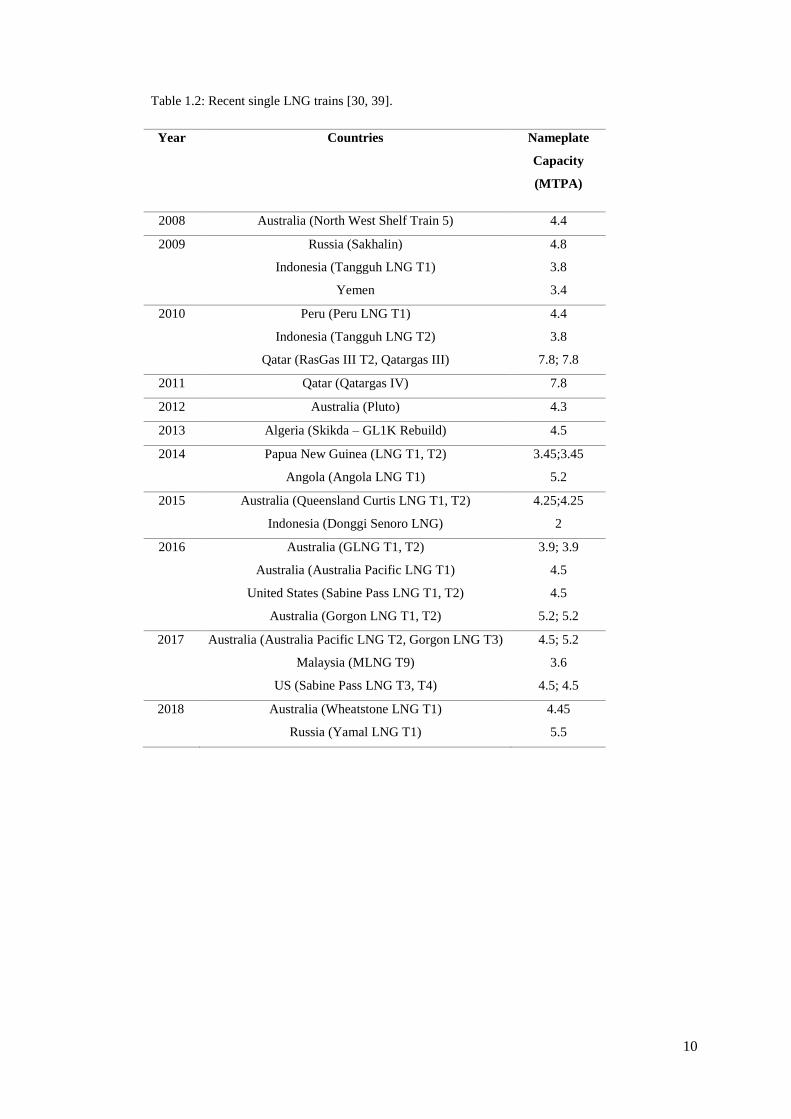
Table 1.2: Recent single LNG trains [30, 39].
Year Countries Nameplate
Capacity
(MTPA)
2008 Australia (North West Shelf Train 5) 4.4
2009 Russia (Sakhalin)
Indonesia (Tangguh LNG T1)
Yemen
4.8
3.8
3.4
2010
Peru (Peru LNG T1)
Indonesia (Tangguh LNG T2)
Qatar (RasGas III T2, Qatargas III)
4.4
3.8
7.8; 7.8
2011 Qatar (Qatargas IV) 7.8
2012 Australia (Pluto) 4.3
2013 Algeria (Skikda – GL1K Rebuild) 4.5
2014 Papua New Guinea (LNG T1, T2)
Angola (Angola LNG T1)
3.45;3.45
5.2
2015
Australia (Queensland Curtis LNG T1, T2)
Indonesia (Donggi Senoro LNG)
4.25;4.25
2
2016
Australia (GLNG T1, T2)
Australia (Australia Pacific LNG T1)
United States (Sabine Pass LNG T1, T2)
Australia (Gorgon LNG T1, T2)
3.9; 3.9
4.5
4.5
5.2; 5.2
2017 Australia (Australia Pacific LNG T2, Gorgon LNG T3)
Malaysia (MLNG T9)
US (Sabine Pass LNG T3, T4)
4.5; 5.2
3.6
4.5; 4.5
2018 Australia (Wheatstone LNG T1)
Russia (Yamal LNG T1)
4.45
5.5

11
Figure 1.7 and Table 1.2 show that future LNG trains will be built as single large LNG
trains. Single large LNG trains not only help to reduce the production cost but also improve
project economics [26, 30, 40-43]. However, these benefits can only be achieved when the
plant applies proven LNG technology and equipment, availability of large gas reservoirs, has
a robust design, high plant reliability and availability is maintained, the process is simple and
easy to operate and is provided with sufficient spare equipment in the case of sudden trip or
shutdown. Meanwhile, very few studies are available that discuss ways to improve single
large LNG train efficiencies [42, 44-46].
On the other hand, future LNG plants can be improved by integrating a single large LNG
train with the NGL plant. In the past, LNG liquefaction trains were designed as a stand-alone
unit [40] with no NGL plant. By installing the NGL facilities, the need for a scrub column
which typically is used in the liquefaction plant to remove aromatics and heavy
hydrocarbons can be eliminated [30]. Further, employing an integrated design reduced the
total equipment count. For example, by utilizing common processing equipment such as
refrigeration system (propane refrigeration cycle) [33, 34] will decrease the capital and
operating cost of the plant. Also, the energy requirements for separation, condensation and
cooling of the NGL products can be shared from the liquefaction section [40]. With this heat
integration, the overall plant process efficiency can be improved [32, 47]. Besides, having an
integrated design makes LNG plants more robust. For instance, the LNG capacity can be
adjusted especially when fluctuations occur in the LNG market. In addition, the plant will be
able to handle a wide range of feed gas compositions which helps in meeting the LNG HHV
specification. Till today, no study is available that discusses the improvement of the
integrated LNG/NGL design for single large train and its effect on the LNG HHV
specification.

12
Another important subject area of focus is the usage of suitable methods to optimise the
LNG plants. As discussed in section 1.3, the optimisation of LNG plants is a complex and
time- consuming process which requires appropriate methods. Numerical and
thermodynamics-based approaches are two common techniques which are mostly being
applied to optimise the LNG plants. Some examples of numerical methods are linear (mixed
integer) and nonlinear programming, deterministic and nondeterministic and stochastic
approach [26]. However, there are some weaknesses discovered using these approaches. For
instance, deterministic approach excludes the uncertainties changes involved in the process
design and applying incomplete mathematical models within the process flow sheet program
[30, 48], thus, it is not considered as the preferred method for most actual engineering
problems [30]. Disregarding these aspects may cause infeasible design or inferior
performance of the process. On the other hand, a nondeterministic approach (genetic
algorithm and tabu search) requires long execution time which sometimes prevents it to
reach the global optimum [49]. Additionally, the optimisation results obtained using
numerical based methods causes ambiguity because it is not embedded with any process
knowledge, hence gives no understanding of the process.
Meanwhile, the energy and exergy analyses are the methods that apply thermodynamics
concepts. These methods are derived from the first and second law of thermodynamics. They
have been widely used in numerous studies to evaluate the liquefaction process
thermodynamics efficiency, assist in obtaining an optimal design and operation and improve
the entire plant performance [50-56]. Hence, using the correct methods will not only
optimise the LNG plant efficiency but also helps to understand the insight of a process.
Table 1.3 shows the summary of the work done by the previous researchers using numerical
and thermodynamic optimisation methods.
Table 1.3: Numerical and thermodynamic optimisation methods done by previous researchers.
Optimisation methods Publication
Thermodynamics Mehrpooya, Jarrahian [50], Kanoglu [51], Najibullah Khan,
Barifcani [52], Najibullah Khan, Barifcani [53], Remeljej and
Hoadley [54], Vatani, Mehrpooya [55], Cipolato, Lirani [56]
Numerical Lee, Smith [57], Nogal, Kim [58], Wang, Zhang [49],
Cammarata, Fichera [59], Aspelund, Gundersen [60]

13
In this research work, the thermodynamics approach i.e. energy and exergy analyses are used
to overcome the limitations of the numerical optimisation methods. Knowing the
thermodynamics properties (enthalpy and entropy) of each process stream is crucial as it
provides a better understanding of the changes occurring within the process.
1.6 Scope and objectives of this study
This thesis focuses on ways to optimise the process efficiency of a single large LNG train
that employed Cascade LNG process. The optimisation was carried out from operational and
design perspectives for a 5 MTPA production plant using energy and exergy analyses
methods. The study covers modelling of cascade LNG process, optimisation of the pre-
cooling cycle, process efficiency analysis of two different integrated LNG/NGL
configurations and optimisation through the deethaniser (De-C2) column pressure. The
detailed objectives are as below:
1. Develop a cascade LNG process simulation model using Aspen HYSYS (v.7.2,
2010). The pre-treatment unit is not modelled as the main emphasis is on the
liquefaction section.
2. Optimise a three-stage propane pre-cooling cycle by varying the cooling load at the
intermediate stages of propane evaporators and investigate its effect on the process
parameters and efficiency.
3. Analyse the process efficiency of two different integrated LNG/NGL configurations
that meet the prescribed LNG specification. The integrated LNG/NGL process
model applies the optimal operating conditions for propane pre-cooling cycle based
on the findings obtained from objective number 2.
4. Examine the effect of deethaniser (De-C2) column pressure on the process
parameters and efficiency of the integrated LNG/NGL process. The integrated
LNG/NGL process model uses the configurations that give the highest process
efficiency and meet the specified LNG specification based on the findings obtained
from objective number 3.

14
1.7 Contributions of this thesis
Upon addressing the above objectives, the following are some important contributions made
from the research work conducted through multiple simulations and thermodynamics
analyses of cascade LNG process. These contributions are:
1. A new optimised design has been developed for cascade LNG process that includes
integration with the NGL section specifically for large-scale LNG train; 5 MTPA
production plant.
2. Introduced a new method that can improve the propane pre-cooling cycle efficiency
by varying the cooling load across various compression stages. An optimised set of
operating conditions for the propane evaporator has been obtained.
3. Based on the optimised operating conditions of the pre-cooling cycle, the integrated
LNG/NGL cascade simulation is further improved by comparing two distinct
integrated designs. An optimised integrated design has been obtained that not only
improves the process efficiency but also meets the prescribed LNG HHV. A
significant reduction in power consumption has been observed.
4. An important operating parameter has been discovered that plays a vital role in
determining the LNG production and it prescribes HHV, that is the De-C2 column
pressure. Based on the results obtained in Chapter 6 of this thesis, the LNG capacity
and its HHV specification hinge on the De-C2 column pressure.
5. The usage of energy and exergy analyses in this research work provides a clear
understanding of the process. This is through identifying the inefficiency
occurrences in the equipment, hence assist in optimising the process by making the
necessary changes to the operating parameters.

15
1.8 Thesis outline
This thesis discusses the presented work in the following chapters.
Chapter 1
In this chapter, an introduction about LNG has been given that covers its role as a future
energy provider. This chapter also includes the following topics; overview of LNG plant
processes, the importance of optimisation, issues and suggestions to improve the LNG
plants, scope, objectives and contributions of this thesis. At the end of this chapter, a brief
thesis outline is presented that summarised the overall research work.
Chapter 2
This chapter is the literature review of the research study. Firstly, this chapter discusses
various LNG processes that are suitable for large-scale single LNG train followed by the
reason for selecting cascade over the other refrigeration processes. Next, this chapter
describes the fundamentals involved in the liquefaction of natural gas processes such as the
thermodynamic laws, heat exchange terminologies and refrigeration systems. This chapter
further discusses the energy and exergy methodologies used to complete the research study.
Lastly, this chapter describes the optimisation areas such as the pre-cooling cycle, integrated
LNG/NGL section and NGL process and identifies the study gaps in each of these areas.
Chapter 3
This chapter discusses the simulation basis and modelling assumptions applied in all the
simulation work. It also explains the simulation constraints needed for each research work.
This chapter also provides the base case process simulation flow scheme of Aspen HYSYS,
the stream properties and composition. The base case simulation model is used to optimise
the cascade LNG process. Besides, a brief description is given on the optimisation
framework and verification of the simulation model.
Chapter 4
In Chapter 4, a three-stage propane pre-cooling cycle process efficiency is optimised. It used
the base case simulation modelled that was presented in Chapter 3. The process efficiency
optimisation framework of the pre-cooling cycle is also explained. The effect of varying the
process parameters such as cooling load (duty), pressure and temperature of propane
evaporator on the process performance and efficiency will be analysed and discussed.

16
Chapter 5
In this chapter, the simulation model of the integrated cascade process is further optimised
by modifying the process configuration. These models use the optimal operating conditions
for pre-cooling cycle based on results obtained in Chapter 4. Two different configurations of
the integrated LNG/NGL cascade process are studied. The effect of changing the process
configurations on the process parameters, efficiency and LNG HHV specification is analysed
and evaluated.
Chapter 6
This chapter analyses the effect of varying the De-C2 column pressure on the process
performance and overall efficiency. The simulation model uses the optimal integrated design
based on the results obtained from Chapter 5.
Chapter 7
This chapter concludes the overall findings based on the results presented from Chapters 4 to
6. The percentage increase in overall process efficiency because of optimisation are
discussed. Further, recommendations for future studies have been proposed based on the new
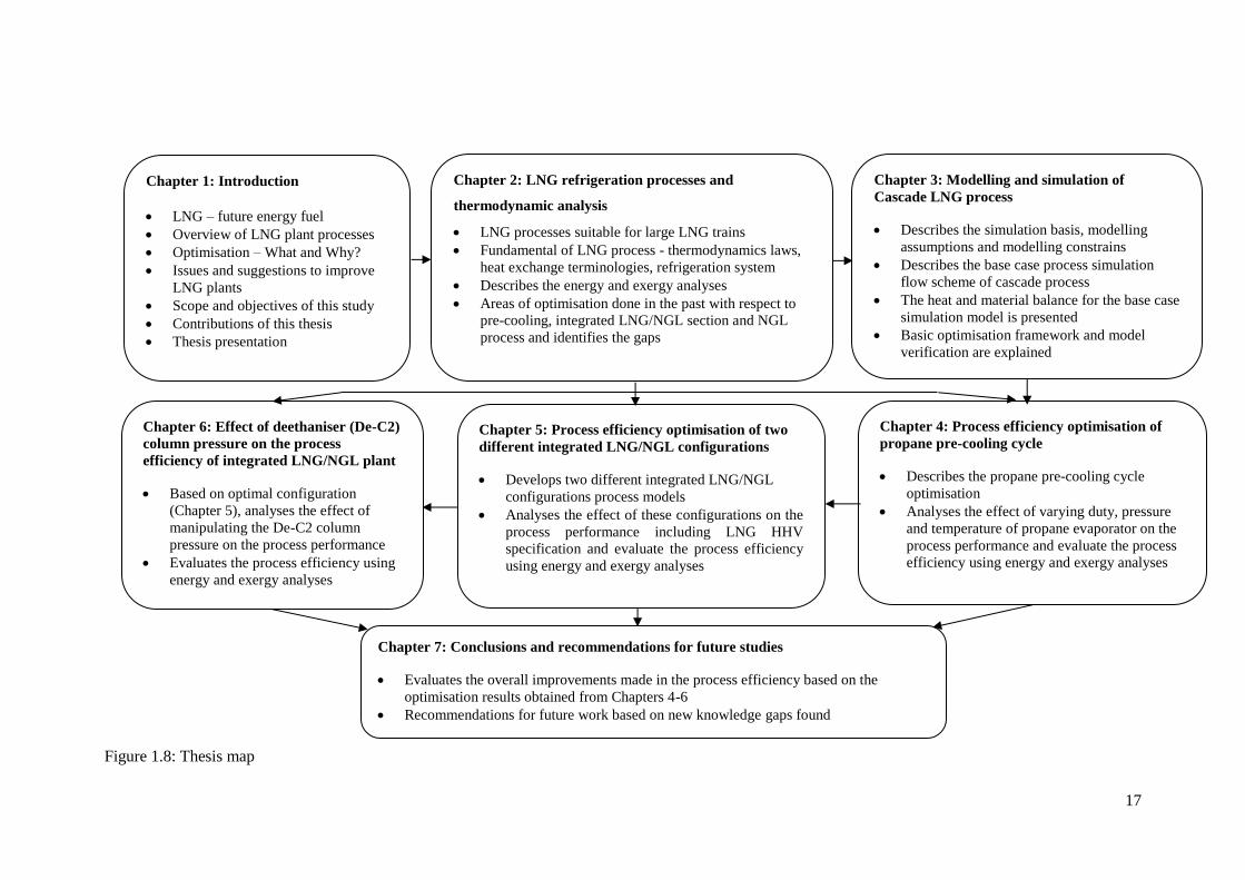
knowledge gaps found. The overall thesis process map is shown in Figure 1.8.
The content of this thesis is presented in a hybrid format. Chapters 2, 3, 4 and 5 contents are
referred to journal articles that have been published in the Journal of Natural Gas Science
and Engineering and The APPEA journal. The presentation of the content is partially
adjusted to be consistent with the research flow and thesis style.
17
Figure 1.8: Thesis map
Chapter 1: Introduction
• LNG – future energy fuel
• Overview of LNG plant processes
• Optimisation – What and Why?
• Issues and suggestions to improve
LNG plants
• Scope and objectives of this study
• Contributions of this thesis
• Thesis presentation
Chapter 2: LNG refrigeration processes and
thermodynamic analysis
• LNG processes suitable for large LNG trains
• Fundamental of LNG process - thermodynamics laws,
heat exchange terminologies, refrigeration system
• Describes the energy and exergy analyses
• Areas of optimisation done in the past with respect to
pre-cooling, integrated LNG/NGL section and NGL
process and identifies the gaps
Chapter 3: Modelling and simulation of
Cascade LNG process
• Describes the simulation basis, modelling
assumptions and modelling constrains
• Describes the base case process simulation
flow scheme of cascade process
• The heat and material balance for the base case
simulation model is presented
• Basic optimisation framework and model
verification are explained
Chapter 4: Process efficiency optimisation of
propane pre-cooling cycle
• Describes the propane pre-cooling cycle
optimisation
• Analyses the effect of varying duty, pressure
and temperature of propane evaporator on the
process performance and evaluate the process
efficiency using energy and exergy analyses
Chapter 5: Process efficiency optimisation of two
different integrated LNG/NGL configurations
• Develops two different integrated LNG/NGL
configurations process models
• Analyses the effect of these configurations on the
process performance including LNG HHV
specification and evaluate the process efficiency
using energy and exergy analyses
Chapter 6: Effect of deethaniser (De-C2)
column pressure on the process
efficiency of integrated LNG/NGL plant
• Based on optimal configuration
(Chapter 5), analyses the effect of
manipulating the De-C2 column
pressure on the process performance
• Evaluates the process efficiency using
energy and exergy analyses
Chapter 7: Conclusions and recommendations for future studies
• Evaluates the overall improvements made in the process efficiency based on the
optimisation results obtained from Chapters 4-6
• Recommendations for future work based on new knowledge gaps found

18
Chapter 2 LNG refrigeration processes and thermodynamic
analysis
2.1 Introduction
In this chapter, the literature review is sub-divided into three main topics which are the LNG
processes for a single large-scale LNG train, refrigeration systems and methods to evaluate
the process efficiency using energy and exergy analyses and LNG processes optimisation.
2.2 LNG processes for a single large-scale LNG train
As discussed in Chapter 1 (section 1.5), the current trend of LNG plants focuses on building
a single large-scale LNG train (3 to 8 MTPA) which provide economic benefits. The type of
LNG process determines the size of the LNG train. With the recent technological
advancement in the LNG technologies, existing liquefaction processes are upgraded and new
liquefaction processes are invented that are suitable for large-scale LNG trains. The
following are the liquefaction processes that are suitable for a single large LNG train;
propane pre-cooled mixed refrigerant (C3MR) and AP-XTM by APCI, dual mixed refrigerant
(DMR) by Shell-APCI, parallel mixed refrigerant (PMR) by Shell, LiquefinTM process by
IFP/Axens, mixed fluid cascade (MFC) by Linde-Statoil and Phillips optimised cascade
(POC) LNG process by ConocoPhillips. These processes will be discussed in the next
section.
2.2.1 Propane pre-cooled mixed refrigerant (C3MR) process
The C3MR process licensed by APCI was first applied in Brunei LNG plant in the year 1972
and about 75% of the existing baseload LNG plants use this process [30]. As shown in
Figure 2.1, this process consists of pre-cooling and liquefaction cycles. Pre-cooling of
natural gas is achieved using pure propane while liquefaction of natural gas is attained using
mixed refrigerant (MR) which comprises of nitrogen (N2), methane (CH4), ethane (C2H6),
propane (C3H8) and butane (i/n-C4H10). In the pre-cooling cycle, pure liquid propane (green
stream) cools natural gas and MR streams (blue stream) to about -35oC to -40oC [30, 61] in
three or four pressure stages. The pre-cooling of these streams is done in kettle type heat
exchangers (see Figure 2.2 [62] ). The cooling of natural gas and MR causes the liquid
propane to evaporate. This vaporised propane is then compressed to 15 – 25 bara [61] and
condensed against ambient air or cooling water and recycled to the propane kettles.

19
Meanwhile, the partially condensed MR exit the propane cycle and is then separated into
vapour and liquid streams in the high pressure (HP) separator. These MR streams are used to
liquefy and sub-cool the natural gas to about -150oC to -162oC [41, 63] in the main cryogenic
heat exchanger (MCHE). The liquid and vapour MR streams enter the MCHE tubes from the
bottom. The MCHE consists of two sections called the cold bundle (CB) and warm bundle
(WB).
The liquid MR stream exits the WB or middle bundle and is flashed across the JT valve on
the shell side of MCHE. It then flows downward and evaporates providing cooling to the
WB. Whereas, the vapour stream MR goes through the top of MCHE (CB) whereby it is
liquefied and sub-cooled. It is then flashed across the JT valve into the shell side of MCHE.
It flows downward and evaporates providing cooling to natural gas in CB and mixed with
liquid MR sharing the cooling duty for the lower bundles. The overall vaporised MR exit the
shell side of the MCHE and is compressed to about 45-48 bara [61]. It is then cooled by air
or cooling water and then partially condensed by propane refrigerant prior to entering back
in the MCHE. This process has been applied in the existing LNG plants with the capacities
range from 1 to 4 MTPA per train without any major modification on the existing
configuration. For a train capacity reaching 5 MTPA, split MR configuration is applied [40,
64] because the propane compressor reaches its maximum flow capacity [65].
Figure 2.1: APCI Propane pre-cooled mixed refrigerant (C3MR) process; adapted from [26].
Main cryogenic
heat exchanger
Feed gas
Mixed refrigerant
cycle
MR compressor
Vapour MR
Liquid MR
Propane
compressor
Propane
Propane pre-cooling
LNG
CB
WB
Hot
Cold

20
Figure 2.2: Propane kettle exchangers in LNG plants [62].
2.2.2 Split MR process
The APCI split MR or known as split C3MR process was developed to overcome the power
imbalance between the propane and MR cycles [66] in the C3MR process. The process
configuration for this process is the same as the C3MR process. The only difference is the
arrangement of the gas turbines (GT) in the propane and MR cycles. As shown in Figure 2.3
this process utilises two GE Frame 7EA GT; the first GT drives the high-pressure MR (HP
MR) and propane compressor together on the same shaft while the second GT drives the low
and medium pressure MR (LP MR and MP MR) compressors only [67]. The propane
compressor used here is of a single casing [40]. Besides, a helper motor below 20 MW is
also installed in both cycles [40]. The available power from all the GTs and helper motors
are fully utilised [30, 40, 67]. The HP MR consumes about 30% of the load from the GT. By
having this process configuration, some of the MR load is transferred to the propane cycle
and the power distribution between the two GTs [66] are equalised. This process has been
applied in Rasgas train 3,4,5, Qatar [68]. The Rasgas train 3 capacity achieved is 4.7 MTPA
[66]. Above 5 MTPA capacity, the propane compressor casing is increased into two but
driven on the same shaft [40].
Figure 2.3: APCI Split MR (Split C3MR) process [64].
Helper HP Propane GE Frame 7EA
Helper MP MR LP MR GE Frame 7EA
HP = high pressure
MP = medium pressure
LP = low pressure

21
2.2.3 AP-XTM process
The APCI-AP-XTM process shown in Figure 2.4 [26] is derived from the C3MR process.
This process consists of pre-cooling, liquefying and sub-cooling cycles. The process
configuration of the pre-cooling and liquefying is similar to the C3MR process; however,
two propane compressor casings are utilised. The natural gas feed stream is pre-cooled using
pure liquid propane (green stream) and it is liquefied to about -120oC using MR (blue
stream) [26]. The only difference is the sub-cooling of natural gas is achieved using nitrogen
refrigerant (purple stream).
The cold low-pressure N2 gas from N2-expander enters the MCHE from the top and sub-
cools the natural gas. It is then pass through the plate fin heat exchanger (PFHE) followed by
compression to high pressure. Next, this high-pressure N2 gas is cooled using air and re-
enters the PFHE to be further cooled by the low-pressure N2 gas. The high-pressure N2 gas is
then expanded to lower pressure in the N2-expander for final sub-cooling of the natural gas.
The MCHEs are used for MR liquefaction and nitrogen sub-cooling cycles.
The AP-X process not only reduces the refrigerant flow rate of propane and MR but also
enables a significant increase in the LNG capacity (approximately 8 to 10 MTPA) for a
single train [30, 40, 69]. This process is suitable for a train size of 6.5 MTPA and beyond
[40]. The first AP-X process was built in Qatar in 2008 with a nameplate capacity of 7.8
MTPA per train and it utilised three frame 9 gas turbines [40, 70]. The AP-X process layout
is illustrated in Figure 2.5 [69].

22
Figure 2.4: APCI-AP-XTM process; adapted from [26].
Figure 2.5: AP-X LNG process layout [69].
Feed gas
Mixed refrigerant
cycle
MR compressor
WB
CB
Coil wound
heat exchanger
Vapour MR
Propane
compressor
Propane drum
Liquid MR
Propane pre-cooling cycle
Nitrogen
expander
PFHE (N2 economiser)
LNG
Sub-cooling cycle
Nitrogen compressor
Coil wound
heat exchanger
MCHE
LNG
Sub-cooler
N2 Economiser
Boxes
Cryomachinery compander /
expander system
35 35

23
2.2.4 Dual mixed refrigerant (DMR) process
The licensors of DMR process are APCI and Shell. They developed this process to overcome
the propane compressor size limitation [26]. The APCI-DMR version is shown in Figure 2.6
[71]. This process is a modification of the C3MR process whereby the pre-cooling cycle uses
MR instead of pure propane. The pre-cooling MR can be formulated, for example using a
mixture of propane and ethane [26, 30] or other components (methane, ethane, propane and
butane) [71]. The MR mixture of the pre-cooling cycle is called warm MR (green stream).
Both pre-cooling and liquefaction cycles use MCHEs supplied by Linde or APCI and the
power requirement differs for each cycle [26].
In this process, natural gas feed is firstly pre-cooled to an approximate temperature of -50oC,
followed by liquefaction and sub-cooling to -153oC using MR mixture of nitrogen, methane,
ethane and propane [26] or called as cold MR (blue stream). The APCI-DMR process uses
two compression stages for the pre-cooling cycle. The warm MR vapour leaving the MCHE-
precooler is compressed in the first compressor. Next, the compressor discharge vapour is
partially condensed and separated in a separator. The vapour from the separator is then
further compressed in the second compressor while the liquid is pumped and mixed with the
second compressor outlet. The mixed warm MR stream is then cooled prior to entering the
MCHE-precooler. In the MCHE-precooler, the warm MR is flashed across a JT valve to
provide cooling for the natural gas and cold MR streams.
Meanwhile, the cold MR enters the MCHE-liquefier to liquefy and sub-cool the natural gas.
The process configurations can be modified and optimised to meet the project requirements
[71]. The DMR process was first deployed in Sakhalin, eastern Russia for two trains each
with 4.8 MTPA capacity. The trains used two MCHEs, cooled using ambient air enhanced
by cold climate. Due to less number of equipment, the DMR process has also been selected
for many FLNG projects [72].

24
Figure 2.6: APCI- Dual mixed refrigerant (DMR) process; adapted from [71].
2.2.5 Parallel mixed refrigerant (PMR) process
Shell introduced another process called the parallel mixed refrigerant (PMR) which is an
enhancement of the DMR process. As illustrated in Figure 2.7 [59], this process is similar to
the DMR process as it uses two MCHEs for the cooling cycles. The PMR process can utilise
either pure propane or MR as a refrigerant for the pre-cooling cycle.
As depicted in Figure 2.7, natural gas feed is first cooled in the MCHE – precooler followed
by liquefaction and sub-cooled in the MCHE-liquefier. The vapour MR exiting the MCHEs
is compressed and finally condensed prior to entering the MCHEs. In both cycles, electric
motors are used to drive the refrigerant compressors [60] instead of the gas turbines. These
compressors are set in parallel arrangement around each of the MCHE which helps to reduce
the pressure drop across the system, hence enhances the process efficiency [59]. The PMR
process can yield about 8 MTPA LNG capacity using existing compressors [59].
LNG
Cold
Warm MR
Treated feed gas
MCHE-Precooler MCHE-Liquefier

25
Figure 2.7: Shell - Parallel mixed refrigerant (PMR) process; adapted from [73].
2.2.6 LiquefinTM process
The LiquefinTM process was invented by IFP/Axens as shown in Figure 2.8 [74]. This
process was developed to obtain a high LNG capacity using simple equipment setup with the
aid of standard compressors [74, 75]. Both pre-cooling and liquefaction of natural gas are
carried out using two different sets of MR compositions which are known as the heavy
(green stream) and the light MR (purple stream). The heavy MR is used for the pre-cooling
cycle while the light MR is used for liquefaction and the sub-cooling cycle. The MR is
composed of nitrogen, methane, ethane, propane and butane [26, 61].
The overall conversion process of natural gas into liquid takes place in a bank of brazed
aluminium plate-fin heat exchanger (BAPFHE). The BAPFHE is divided into two sections;
pre-cooling and cryogenic section. In the pre-cooling section, the heavy MR pre-cools the
natural gas feed, cools and condenses the light MR to about -50oC to -80oC [30, 76] at three
different pressure levels. The pre-cooled natural gas is then separated from the NGL in a
separator and re-enters the cryogenic section of the BAPFHE. Meanwhile, the condensed
light MR exiting the BAPFHE is expanded and returned to the cryogenic section of
BAPFHE to liquefy and sub-cool the natural gas. The light MR leaving the BAPFHE is
compressed by two compression stages and cooled before re-entering the top of BAPFHE.
The pre-cooling and liquefying-sub-cooling cycles are designed such that the power-sharing
is 50-50 for both cycles [77] to ensure that the same compressor driver can be used [26]. The
BAPFHE can be manufactured by any independent supplier as it is non-proprietary
equipment.
Treated feed gas M M
Fuel
LNG
MCHE-Precooler MCHE-Liquefier

26
IFP/Axens stated that about 20% of total cost savings per tonne of LNG can be achieved
compared to the C3MR process [78]. Nevertheless, the industries continue to have some
doubts with regards to the commercial benefits claimed because no plant has yet been built
using this technology. This process is suitable for a base load single LNG train up to 6
MTPA [61].
Figure 2.8: IFP/Axens - LiquefinTM process; adapted from [74].
2.2.7 Mixed fluid cascade (MFC) process
The mixed fluid cascade (MFC) process was developed by Linde in collaboration with
Statoil for LNG plants that are particularly located in the extreme environment. This process
was selected for Snohvit LNG, Norway and installed on Melkoya Island, offshore
Hammerfest (Northern North Sea) as depicted in Figure 2.9. The capacity of this single train
is 4.3 MTPA [30]. This process consists of three cycles; pre-cooling, liquefaction and sub-
cooling cycle. This process is solely utilising MR composed of nitrogen, methane, ethane
and propane [26, 30, 61]. A different set of compositions are applied for each cycle. As
shown in Figure 2.10 [79], the treated feed gas is pre-cooled, liquefied and sub-cooled using
MR 1, MR 2 and MR 3 respectively in three separate cycles.
Heavy MR
pre-cooling cycle
Light MR liquefying
and sub-cooling cycle
Plat- fin heat
exchanger (PFHE)
Treated feed gas
LNG
NGL
MR liquid
expander
Pre-cooling
Cryogenic

27
The pre-cooling cycle uses two PFHEs, whereas the liquefaction and sub-cooling cycles are
employed with Spiral wound heat exchangers (SWHEs) made by Linde [80]. The SWHE can
also be used for the pre-cooling cycle. Frame 6 and Frame 7 gas turbines can be used for a
train size above 4 MTPA. The unique feature of this process is that the Snohvit LNG was the
first and only major base load plant that used electric motors whereby three of 65 MW load-
commutated inverter (LCI) drivers were installed for the purpose of start-up and variable
speed control [68]. Till today, only one plant has been built using MFC process. Besides,
since its start up in 2007, the plant has faced various operational issues. It has been reported
that the heat exchangers were not performing well and require replacement [30].
Figure 2.9: Snohvit, LNG, Norway site construction (the year 2004) [81].
Figure 2.10: Statoil/Linde - Mixed Fluid Cascade (MFC) process; adapted from [79].
LNG Treated feed gas
Sub-cooling
Liquefaction
Pre-cooling cycle
PFHE SWHE SWHE
MR 1
MR 2
MR 3

28
2.2.8 Phillips optimised cascade (POC) LNG process
The early version of Phillips cascade LNG process was developed in the 1960s. In 1969, this
process was applied in Kenai LNG, Alaska with a single train capacity of 1.5 MTPA. The
plant was built by Bechtel, United States (US) engineering company. Later, Phillips
developed a new version of the cascade process called ‘Phillips optimised cascade LNG
process’ and in 1999, it was applied in the Trinidad LNG plant [82].
As shown in Figure 2.11 [83], this process utilises three pure refrigerants namely propane,
ethylene and methane for pre-cooling, liquefaction and sub-cooling cycles respectively. The
pre-cooling cycle uses core-in-kettle type heat exchangers while the liquefaction and sub-
cooling cycles employ a series of brazed aluminium PFHE heat exchangers arranged in
vertical cold boxes [26]. In the pre-cooling cycle, the propane cools the natural gas and
methane while it condenses the ethylene at approximately -30oC [84]. The removal of
compression heat and condensation of propane is achieved using air or cooling water.
Following the pre-cooling cycle, natural gas and methane are liquefied using ethylene to
about -90oC [84]. Meanwhile, the heavier hydrocarbons are separated from natural gas after
one or more stages of chilling by ethylene refrigerant. Finally, the condensed natural gas is
sub-cooled by methane refrigerant to around -150oC [84]. In the case where N2 present in the
methane refrigerant, a slip stream is drawn off to be used as fuel to avoid build-up of inerts
[30]. The cooling of natural gas in each cycle occurs in two or three compression stages.
On the other hand, the POC LNG process applied ‘two trains in one’ configuration as
depicted in Figure 2.12 [85]. As shown in Figure 2.12, each refrigeration circuit has two
parallel compressors/drivers sets arrangement to serve the liquefaction exchangers. This
approach improves the plant reliability and availability [26, 84-86], also assists in
maintenance facility planning and provides highest turndown flexibility [84, 85, 87]. Highest
turndown flexibility here is referring to continuous production even at a low rate; 0 to 100%
or 60 to 80% capacity can be attained in the case where any of the refrigerant compressors is
not in operation [87]. Additionally, this concept also saves time because it prevents shutting
down the whole train due to repairing a machine [86]. Further, the usage of this unique
design plus pure refrigerants helps to balance the power loads in each circuit [30, 82].

29
Though this concept increases the number of compressors/drivers per train, the overall power
requirement for this process is relatively low [26]. Furthermore, according to Finn, Johnson
[88], this process requires a small heat exchanger surface area per unit of capacity. This
made the cascade LNG process suitable for large capacity trains as the low power demand
and small heat exchanger size offsets the cost of having multiple machines [86]. This was
proven in the year 2005, whereby the first single large LNG train was built in Trinidad
(Train 4) with a capacity of 5.2 MTPA utilising POC LNG process [85, 87, 89]. This was
considered a significant breakthrough in the liquefaction technology for the LNG industry.
Another essential point to mention is that the latest design of POC LNG process utilises
aero-derivative gas turbines (Figure 2.13) which are light in weight, higher in efficiency [90]
and consume less fuel gas. The overall process design has also been improved by having
integrated heavies removal and nitrogen rejection units [85]. Additionally, this process has
been widely applied across the world regardless of the climate conditions as shown in Table
2.1.
Figure 2.11: Phillips optimised cascade LNG process; adapted from [83].
BAHX
Liquefaction cycle
Sub-cooling cycle Propane
BAHX PFHE
LNG
Methane
Ethylene
Treated feed gas
Pre-cooling cycle
NGL

30
Figure 2.12: 'Two trains in one' concept of COP LNG process [78].
Figure 2.13: Type of gas turbine used in the past, current and future LNG plants that utilised COP
cascade process [85].

31
Table 2.1: List of LNG plants utilising COP cascade LNG process [85].
LNG plants Number
of trains
Total trains
Capacity (MTPA)
Location
Kenai LNG 1 1.5 Alaska, USA
Atlantic LNG 4 14.8 Point Fortin, Trinidad and Tobago
Egyptian LNG 2 7.2 Idku, Egypt
Darwin LNG 1 3.7 Darwin, Australia
Equatorial Guinea LNG 1 3.7 Malabo, Equatorial Guinea
Angola LNG 1 5.2 Soyo, Angola
Queensland Curtis LNG 2 8.5 Curtis Island, Queensland, Australia
Gladstone LNG (GLNG) 2 7.8 Curtis Island, Queensland, Australia
Australia Pacific LNG 2 9.0 Curtis Island, Queensland, Australia
Wheatstone LNG 2 8.9 Ashburton North, Western Australia
Sabine Pass Liquefaction 5 22.5 Cameron Parish, Louisiana, USA
Corpus Christi Liquefaction 2 9.0 San Patricio County, Texas, USA
The summary of the various LNG processes for large-scale LNG plant is given in Table 2.2.
These processes are currently being applied in the LNG plants or may have been proposed
for other LNG projects. In this research study, the cascade LNG process has been chosen as
the preferred liquefaction technology for the production train of 5 MTPA. The detailed
discussion about the selection of this process over other LNG processes is described in the
next section.

32
Table 2.2: Summary of LNG processes for the large-scale LNG plant
Comparison C3MR Split MR (Split
C3MR)
AP-XTM DMR PMR LiquefinTM MFC POC
Nameplate capacity
(MTPA)
1 – 4 4.7 7.8 4.8 8 6 4.3 5.2 (1.5 ~5.2)
*existing plants
Remarks 75% of the world LNG
plants utilised it [30].
Rasgas train 3,4, 5
(Qatar), Damietta
plant, Egypt.
*can reach up to 5
MTPA, > 5 MTPA, 2
propane compressor
casings are required
suitable for train size
6.5 to 10 MTPA [40]
*applied in 6 trains in
Qatar
Sakhalin, Russia
(only)
*suitable for
FLNG projects
no plant has used
this process
*power sharing of
50:50 for both
cycles
Snohvit, Norway
(only)
*this process was
developed for the
extreme location
*can reach up to 8
MTPA [45]
*applied concept of
‘two trains in one’
Proven technology Yes Yes Yes Yes No No Yes Yes
Type of refrigerant
used for each
cooling cycle
Propane – pre-cooling
MR – liquefaction and
sub-cooling
Propane – pre-cooling
MR – liquefaction
and sub-cooling
Propane – pre-cooling
MR – liquefaction
N2 – sub-cooling
MR for all cycles MR for all cycles
*Propane can be
used in pre-cooling
cycle
MR for all cycles MR for all cycles Propane – pre-cooling,
Ethylene - liquefaction
Methane – sub-cooling
Driver Steam turbines and gas
turbines
Gas turbines, helper
motor
*fully utilised power
from all GTs and
helper motors
Gas turbines, expander Gas turbines Electric motor Gas turbines
(standard
compressors)
Electric motor Gas turbines
Major equipment Propane kettle HXs,
MCHE (1), propane
compressor (1), MR
compressors (2)
Propane kettle HXs,
MCHE (1), propane
compressor (1), MR
compressors (2)
Propane kettles HXs,
MCHE (2), PFHE (1),
expander (1), propane
compressor ,2 casings
(1), MR compressors
(2), N2 compressor (1)
MCHE (2), MR
compressors
(pre-cooler and
liquefier)
MCHE (2), MR
compressors
(pre- cooler and
liquefier), PFHE (1),
expander
Brazed aluminium
PFHE (1), MR
compressors,
liquid expander
(1)
PFHE (2), SWHE
(2), MR
compressors (3)
Core in kettle HX,
brazed aluminium HX,
compressors (6)
Proprietary
equipment
Yes, MCHE Yes, MCHE Yes, MCHE Yes, MCHE Yes, MCHE No Yes, SWHE No

33
2.3 Why cascade LNG process?
The success of an LNG project is highly dependent on the type of liquefaction technology
selected [26]. This is because the selected liquefaction process will determine the name plate
capacity, duration of the whole LNG project planning and execution i.e. starting from the
front-end engineering design (FEED) study to construction as well as the overall capital and
operating costs. In this study, the cascade LNG process is chosen due to several reasons. As
explained in section 2.2.8 and Table 2.2, cascade LNG process has established a strong
position in the LNG industry based on its proven track record for more than four decades
since the operation of its first plant; Kenai LNG, Alaska (1969). The concept of ‘two trains
in one’ which has been applied has yields about 95% train availability and improved
reliability [85]. This is proven based on Kenai, LNG plant record whereby the plant has
achieved 38 years of uninterrupted cargo supply to Japanese customers [87, 91]. Other
benefits obtained using this configuration have been discussed in section 2.2.8.
From an operation perspective, the use of pure components instead of MR makes this
process safe, simple to operate and easy to understand [84]. In terms of safety, in the events
of any flare or gas leaks occurring, the operators will take samples of the flare stream to
locate the pressure safety valve (PSV) source or use infrared gas detectors to not only notify
the gas leaks but also the identification of materials released [84]. The operation of this
process is also flexible as each cycle is controlled separately [30], hence the power load
between the cooling cycles can be adjusted by varying the pressure profile [84]. Besides, the
pressure-temperature (PT) curves of the pure refrigerants can be programmed in the
distributed control system (DCS) which assists the operators to act promptly in the case any
refrigerants becoming off spec. Another advantage of using pure refrigerant is it can be
reused after shutdown or major maintenance schedule. Whereas, the MR components (N2,
methane and ethane) can neither be stored nor reused [84] as it is usually flared during major
maintenance schedules or startup as described by Brimm, Ghosh [66] for split MR process
operation.

34
From the design context, the use of brazed aluminium heat exchangers (BAHE) or BAPFHE,
standardised compressor and gas turbine type have helped to reduce the overall capital cost
and duration of building a new LNG plant based on Trinidad LNG plant experience [86, 87].
This is because the exchangers can be purchased from numerous vendors at competitive
prices [84] while Frame 5D gas turbine has a strong position in the market as it has been
widely used in the earlier LNG plants. Meanwhile, there is no major leakage reported using
this exchanger compared to MCHE. In the year 2004, Brunei LNG (BLNG), were involved
in the MCHE replacement project for four trains (Train 1 to 4) due to frequent unplanned
shutdown because of MCHEs leaks [92]. Besides, other LNG plants had also encountered
the same incident, however, these plants are not to be disclosed in this thesis because of
confidentiality reasons.
Figure 2.14: Lifting of Linde MCHE at BLNG plant [92].
Meanwhile, according to Nored [68], many new LNG projects have chosen this process
because it has multiple machines, low driver power and able to utilise aeroderatives gas
turbines. Based on the above discussion, hence the cascade LNG process is chosen for this
research study.

35
2.4 Why 5 MTPA production train?
Numerous studies have been conducted that discussed the future LNG train size capacity.
According to Nored [68], the current optimum LNG train size is in the range of 5 to 6
MTPA. Similarly, Spilsbury, McLauchlin [40] mentioned that the future LNG train size will
be centred to 5 MTPA based on the historical LNG trend size data. In addition, Mokhatab,
Mark [30] stated that the future LNG trains are likely to be in the range of 3 to 6 MTPA
whereas trains size of 8 to 9 MTPA are only suitable in locations where there are very large
gas reserves and huge market demand [45]. LNG train size of 8 MTPA may not be suitable
for every brownfield and greenfield project because it requires continuous high plant
reliability and availability, robust design, also needs to be provided with spare equipment so
that the entire plant does not need to be shut down or started up in the event of equipment
failure [30]. In another study, Eaton, Hernandez [45], categorized the future LNG trains size
into three different capacities; 4 MTPA, 5 MTPA and 8 MTPA. Most of the LNG plants that
have been built after the year 2000, the train capacity is 4 MTPA and suitable for the
greenfield project that has limited gas supply. Meanwhile, the 5 MTPA train is suitable for
the greenfield projects that requires lower equipment costs, have gas supply and sales
availability. It is also the preferred option for LNG expansion projects, especially when
copying an existing train design.
Based on these studies and data presented in Figure 1.7, Figure 2.13, Table 1.2, Table 2.1
and Table 2.2, it concludes that new liquefaction trains that have been built in the past 10
years are in the range of 3.4 to 5.2 MTPA capacities while for mega trains only 6 trains have
been built. Moreover, Table 2.2 shows that only the POC LNG process has a proven track
record that meets the 5 MTPA train capacity without any significant changes made in the
design and meets all the criteria required to build a large LNG train. Based on this evidences
and literature review, 5 MTPA is chosen for this research work.

36
2.5 Fundamentals principles of LNG processes
As mentioned in Chapter 1, section 1.2, liquefaction of natural gas is based on the principle
of a refrigeration system whereby a refrigerant absorbs the heat from the natural gas stream
in successive expansion and compression stages and rejecting it to a higher temperature
using air coolers or cooling water. This process requires a substantial amount of energy
due to the usage of complicated refrigeration systems [26]. To understand better how a
refrigeration system works, it is important to know and understand some basic ingredients of
this system. A refrigeration system applies the fundamental laws of thermodynamics, uses
various heat exchange terminologies such as latent and sensible heat to describe the internal
process of the system and are based on thermodynamics expansion process. The description
of these key elements will be described in the next section.
2.5.1 First and second laws of thermodynamics
The first and second law of thermodynamics is the basic principles used to understand the
operation of a refrigeration system. For a process to occur, both these laws must be fulfilled
[93]. The first law of thermodynamics is defined as the law of conservation of energy i.e.
energy can neither be created nor destroyed and it can only change its form. In
thermodynamics engineering principles, the change in energy of a system is contributed by
kinetic energy (KE), internal energy (u) and potential energy (PE) [94]. Energy can be
transferred to or from a system in three modes; mass, heat and work [93]. One of the
important properties of this law is enthalpy (h) which has the relationship with internal
energy (u), pressure (P) and specific volume (𝑣) and can be defined as below:
h = u + P𝑣
(2.1)
where h and u are in kJ/kg, P is in kPa and 𝑣 is in m3/kg. The product of pressure times
volume is kJ/kg. This property will further be used in the energy balance of a closed system.
The concept of conservation of energy is depicted in Figure 2.15 [30]. As can be seen from
Figure 2.15, a steady state control volume (CV) system where there is mass and energy
entering and leaving the system and there is also heat and work interaction occurring
between the system and the surrounding.

37
Figure 2.15: Steady-state control volume system; adapted from [30].
If the change in the kinetic, internal and potential energies are ignored, the change in the
total amount of energy content of the CV between the inlet (i) and exit (e) of the system can
be expressed as:
∑ ṁi hi -
i
∑ ṁehe +
e
QCV - WCV = 0
(2.2)
where ṁ and h are the mass flow rate and enthalpy for the corresponding stream, QCV is the
heat rate into the system and ẆCV is the work rate leaving the system. As shown in
equation (2.2), the total energy difference of the steady state CV system is zero; hence the
total energy content is conserved. Equation (2.2) also represents the first law of
thermodynamics.
The first law only focuses on the quantity of energy and the transformation of energy from
one form to another regardless of its quality [93]. Conserving the quality of the energy
(potential to produce work) [95] is important to engineers as well as degradation of energy
during a process [93]. The quality of energy can be determined by performing a quantitative
assessment on the system and this is done through the second law of thermodynamics. There
are various statements which have been made to define the second law of thermodynamics.
This is because this law is used to determine the theoretical limits for some of the
engineering systems such as heat engines, refrigerators and also predicting the degree of
completion of chemical reactions [93].
ṁi, hi Control volume
steady state system ṁe, he
ẆCV QCV

38
In this study, the second law of thermodynamics is referred to the Clausius statement which
states that “ it is impossible to construct a device that operates in a cycle and produces no
effect other than the transfer of heat from a lower-temperature body to a higher temperature
body” [93]. This statement explains the working concept of a refrigerator at home. Based on
the Clausius statement, it can be said that a refrigerator will not work unless the compressor
is supplied with power from an external source such as a turbine or an electric motor. The
purpose of refrigeration is to maintain the refrigerated place at a low temperature (TL) by
eliminating heat (QL) from cooled space and rejecting this heat to an external source which is
merely part of the cycle [93].
Figure 2.16 illustrates the working principle of a refrigerator as per the second law of
thermodynamics. As can be seen from Figure 2.16, there is some interaction that can be
observed between the system and the surroundings. Some net effect on the surroundings can
be traced through the utilisation of energy in the form of work in addition to the heat transfer
from the colder region to the warmer region. Hence, the refrigerator complies the Clausius
statement for the second law.
Figure 2.16: Second law of thermodynamics (Clausius statement) - Refrigerator.
Power
Compressor
Air cooler
Evaporator
J-T
Surroundings medium
(kitchen air), at TH > TL
Cold refrigerated
space at TL
QL
QH
System boundary

39
Another important property that is included in applying the second law of thermodynamics is
entropy. Entropy is defined as a measure of molecular arbitrariness or molecular disorder in
a system and it is not conserved. The entropy of a substance is the lowest in the solid phase
and highest in the gas phase [93]. This is because in the solid phase the molecules are
compact and less movement occurs compared to the gas phase where the molecules move
randomly and collide with each other. The presence of entropy will determine whether a
process is reversible or irreversible. A process that does not generate a net entropy is called
reversible. In a reversible process; both the system and surroundings can be exactly restored
to their initial states while for an irreversible process this is impossible. Additionally, in a
reversible process, the energy is neither degraded nor potential to do work is lost.
In an actual process, the amount of energy is always preserved as per the first law, however,
the energy quality is bound to degrade due to the increase in the entropy [93]. The increase
in the entropy occurs because of irreversibilities effects such as friction, unrestrained
expansion of gas or liquid to a lower pressure, compression of gas to a higher pressure,
mixing of the matter of different compositions or states and heat transfer through limited
temperature difference [30, 93]. For example, in Figure 2.17, about 10 kJ of heat is
transferred from the hot medium to the cold medium. During this process, the randomness
and the entropy of the hot medium reduce while the molecular disorder and entropy of the
cold medium increase. At the end of the process, the 10 kJ is still available but at lower
temperature and at lower energy quality because the net entropy increased.
Figure 2.17: Entropy change for a heat transfer process.
Hot medium
90oC
Cold medium
30oC
10 kJ

40
As discussed above, for a process to occur, it must comply both with the first and second law
of thermodynamics. The first law only discusses the change of energy from one form to
another, modes of transfer (heat, work and mass) and the amount of energy of a steady state
CV remains constant. Meanwhile, the second law discusses the requirement of an external
power source to transfer heat from the cold to the hot medium and the potential of producing
work when interacting with the surroundings. Additionally, two important thermodynamic
properties were introduced which are enthalpy and entropy with respect to the first and
second law. The combined application of the first law and second law of
thermodynamics will be used to evaluate the process efficiency and performance of the
liquefaction process in this research work which will be further described in section 2.8
of this chapter.
2.5.2 Heat exchange terminologies of a refrigeration system
There are various heat exchange terminologies applied in a refrigeration process such as
superheat, sub-cooling and sensible and latent heats. It is important to recognize the
definition of these terminologies to understand the thermodynamics and troubleshoot the
refrigeration cycle. These terminologies are explained by using propane as an example in the
propane refrigeration cycle.
2.5.2.1 Superheat
The term superheat is only applicable for a substance that is in a gas or vapour state. For
example, liquid propane has a boiling point of -42oC, at 1 atm. When propane is heated up to
-32oC, it is said that propane vapour contains 10oC of superheat. In the propane refrigeration
cycle, as shown in Figure 2.18, the propane is in vapour phase before entering the
compressor. It is then compressed to a higher pressure; 20.73 bar and has a temperature of
82.6oC. At this stage, the propane is in superheated condition. Desuperheater is used in the
propane cycle to remove this superheat condition. The boiling temperature of a liquid
depends on its pressure. By increasing the evaporator pressure, it increases the boiling point
of the liquid propane. This is because there is more pressure exerted on the liquid surface to
be overcome by the liquid molecules. Hence, by controlling the pressure of the liquid
through the evaporator pressure, the boiling temperature can be altered. This is one of the
important parameters that is used in this study to improve the propane cycle efficiency.
2.5.2.2 Sub-cooling
Sub-cooling is a term applied for a substance which is in the liquid or solid state. For
example, in Figure 2.18 above, the propane is in liquid form after the condenser at a
temperature of 57oC and 19.93 bar. It is the further cooled to 42oC at pressure 19.58 bar. It is
said that the propane has been sub-cooled from 57oC to 42oC that is sub-cooled by 15oC.

41
Figure 2.18: Simplified propane refrigeration cycle.
2.5.2.3 Sensible heat and latent heat
Any change in the temperature of a substance without changes in a phase is called sensible
heat. This change in temperature can be measured using a thermometer. Sensible heat is used
for superheat and sub-cooling as both processes involve changes in temperature. In the
propane refrigeration cycle, for superheated propane, its temperature changes from -37.1oC
to 82.6oC while for the sub-cooled propane, the temperature drops from 57oC to 42oC. Both
these processes don’t involve phase change. Meanwhile, the term ‘latent heat’ or in Latin the
word ‘latent’ means hidden due to this heat cannot be measured by a thermometer as the
temperature remains constant. This latent heat involves phase change of a substance from a
liquid to vapour phase or vice versa and it occurs at a constant temperature. In the propane
refrigeration cycle, the latent heat of vaporisation takes place in the evaporator whereby the
liquid propane is boiled at constant temperature provided the evaporator pressure is
maintained. The quantity of heat (energy) absorbed during vaporisation is equivalent to the
amount of heat (energy) released during condensation and it is specifically called the ‘latent
heat of vaporisation’[93]. The amount of latent heat depends on the temperature or pressure
at which the phase change takes place.
2.6 Thermodynamics expansion processes
The refrigeration system design is based on different thermodynamics expansion processes.
There are three types of thermodynamics expansion processes which have been applied in
the existing LNG plants namely Joule-Thomson (JT) expansion, Brayton expansion and
Claude expansion. Two most commonly used expansion processes are the JT and Brayton.
42oC
19.58 b
57oC
19.93 b
63oC
20.33 b
Propane
compressor
Evaporator
Sub-cooler
JT-valve
Condenser Desuperheater
-37.1oC
1.26 b
82.6oC
20.73 b
-3.52oC
4.28 b

42
2.6.1 Joule Thomson expansion process
During the early developments of LNG plants, the Joule Thomson (JT) expansion process
was the first and the only method applied to cool the gas streams [96]. The JT expansion
process is shown in Figure 2.19 [97]. This expansion process does not involve any work or
heat transfer. This is because the JT valve is insulated which make it adiabatic i.e. no heat
transfer occurs with the surroundings and no net change of internal energy to KE of mass
motion is observed [96-98]. Therefore, the enthalpy of the fluid (refrigerant) remains
constant, hence it is an isenthalpic expansion process. The JT expansion works by throttling
a refrigerant via a flow resistor such as valve or orifice [96] whereby reverse of the fluid is
impossible, thus it is an irreversible process.
The liquid refrigerant flows across the valve and expanded into two phases; liquid and
vapour. This causes a reduction in the temperature and pressure of the refrigerant. The
cooled refrigerant exchanges heat with natural gas (NG) feed flowing in the counter current
direction. The refrigerant vaporises and is compressed to a higher pressure. Then, the high-
pressure refrigerant is desuperheated using an air cooler (AC) and is condensed in the heat
exchanger (HX) prior to being expanded again via the JT valve. The degree of cooling or
cooling effect is highly dependent on the thermodynamics property of the refrigerant [97].
This is due to the different composition of the refrigerant as both pure and MR can be used
in the JT expansion process. The JT expansion is a simple and low capital cost process [99].
A refrigerant cycle with the JT expansion configuration is known as ‘JT cycle’[97]. In this
study, the cascade LNG process applies to the JT expansion process.
Figure 2.19: JT expansion; adapted from [97].
JT
LNG
NG AC C
HX
HX

43
2.6.2 Brayton expansion process
The Brayton expansion utilises a turbo-expander or an expansion engine. As shown in
Figure 2.20 [97], the Brayton expansion process provides cooling through the isentropic
expansion of a gas at high pressure to lower pressure. The reduction in enthalpy of the
expanded gas stream generates power. The power generated from the expander can be used
to drive the compressor shaft in a refrigeration system [100]. The refrigerant must be in gas
phase throughout the cycle above its saturated vapour pressure to ensure safe operation of
the expander [97]. This process is a reversible process as it is operated isentropically
(constant entropy), hence known as ‘reverse-Brayton cycle’. This expansion process is
suitable for offshore LNG plants and plants with small capacities [30, 100, 101]. The
Brayton expansion process forms the root of liquefaction expander based process [26].
Figure 2.20: Brayton expansion process; adapted from [97].
2.6.3 Claude expansion process
As shown in Figure 2.21, the Claude expansion process is a combination of JT and Brayton
cycles. The cooled high-pressure refrigerant leaving the top HX is separated into two
streams. for further cooling. The first stream is expanded isentropically using an expander
while the second stream is cooled in the subsequent HX and finally throttled through a JT
valve to achieve the lowest temperature. This combined expansion process has been applied
in the AP-X (APCI) liquefaction technology as previously shown in Figure 2.4.
E
NG AC C
HX
HX
LNG

44
Figure 2.21: Claude expansion process; adapted from [97].
2.7 Refrigeration systems
Liquefaction of natural gas is achieved by removing the sensible and latent heat over a wide
range of temperatures with the aid of single or multiple refrigerants [88], hence a complex
refrigeration system is required. Two types of refrigeration systems are available namely
compression refrigeration and absorption refrigeration [102]. In the LNG plants, mostly
compression refrigeration systems are employed [26].
2.7.1 Types of the compression cycle
There are two types of refrigeration compression cycles viz. ideal compression and non-ideal
compression cycle. Ideal here means the process is conducted isentropically i.e. no change in
the entropy [102] and every equipment in the cycle is working perfectly. For example, the
adiabatic efficiency of expanders and compressors are assumed 100% (i.e. isentropic
process) while the heat exchangers minimum temperature difference and pressure drop
across all flow components is zero [97].
HX
HX
HX
LNG
JT
AC NG C
E
HX

45
2.7.1.1 Ideal compression cycle
The ideal compression cycle is shown in Figure 2.22 [102]. This single cycle consists of an
evaporator, a compressor, a condenser and an expander. The working principle of this cycle
is described using a pure refrigerant as the working fluid. The cycle operates as follows. At
point 1, a mixture of vapour and liquid refrigerant enters the evaporator. The liquid
refrigerant absorbs the heat at a constant temperature (isothermal) and pressure (isobaric)
and vaporises; producing the cooling effect prior to exiting the evaporator at point 2. This
heat is called ‘latent heat of evaporation’ as described earlier in section 2.5.2.3. Next, all the
vapour refrigerant is compressed isentropically in the compressor to higher pressure from
point 2 to 3. At point 3, the vapour refrigerant is at superheated state due to the compression
process. Following the compressor, from point 3 to 4 the superheated vapour refrigerant is
desuperheated and condensed at constant pressure in the condenser. This process causes a
decrease in the enthalpy of the refrigerant and it leaves the condenser at saturated liquid
state. Finally, the liquid refrigerant is expanded isentropically in the expander to lower
pressure from point 4 to 1. The expansion of the liquid refrigerant produces a cooling effect
for the refrigeration and the cycle continues.
Figure 2.22: Ideal compression cycle; adapted from [102].
Ideal compressor
Condenser
Evaporator
Ideal expander
1 2
3 4

46
The relationship between temperature (T) and entropy (S) and pressure (P) and enthalpy (H)
of the ideal compression cycle are illustrated in Figure 2.23 and Figure 2.24 respectively.
Figure 2.23 shows the ideal compression on the temperature-entropy (T-S) diagram. The
diagram is a two-phase envelope of a refrigerant; right-hand side of the curve indicates that
the refrigerant is in the vapour (V) phase, inside the curve the refrigerant present in both
liquid (L) and vapour (V) phases and to left-hand side of the curve, the refrigerant is in liquid
(L) phase. Beginning from point 1 to 2, the refrigerant in two-phase mixture enters the
evaporator where isothermal vaporisation takes place. From point 2 to 3, the vaporised
refrigerant is compressed isentropically in the compressor and this stage is assumed to be
ideal. The isentropic process ends at point 3. Next, the superheated refrigerant is first
desuperheated (remove heat) and finally condensed isothermally in the condenser to point 4.
At this stage (4), the refrigerant is in a saturated liquid state. Lastly, from point 4 to 1, the
liquid refrigerant is expanded isentropically and this expansion is ideal where no entropy
increase occurs.
Figure 2.23: Ideal compression cycle on temperature-entropy (T-S) diagram; adapted from [102].
Meanwhile, Figure 2.24 shows the same cycle represented on pressure-enthalpy (P-H)
diagram. As can be seen from Figure 2.24, the enthalpy of the refrigerant rises from point 1
to 2 in the evaporator. Then, from point 2 to 3, an increase in the pressure and enthalpy of
compressor occurs. Next, from point 3 to 4, the pressure remains unchanged but a decrease
in the enthalpy is observed due to desuperheating and condensation. Finally, the decrease in
pressure occurs in the expander from point 4 to 1 and since the expansion is isentropic, drop
in enthalpy is observed.
4
3
2 1 Evaporator
Condenser
Two-phase
envelope
Desuperheating
V L V and L
T
S

47
Figure 2.24: Ideal compression on pressure-enthalpy (P-H) diagram; adapted from [102].
2.7.1.2 Non-ideal compression cycle
The non-ideal compression cycle is shown in Figure 2.25 [102]. This single cycle is made up
of an evaporator, a compressor, a condenser and a valve. The cycle operation is the same as
the ideal-compression cycle; however, the compression of the refrigerant features non-
isentropic and the expansion is done at constant enthalpy (i.e. isenthalpic) using an
expansion valve instead of the ideal expander.
Figure 2.25: Non-ideal compression cycle; adapted from [102].
Figure 2.26 [102] represent the non-ideal compression on the temperature-entropy (T-S)
diagram. The cycle operates at the same condition from point 1 to 2 and 3 to 4 as per the
ideal compression. However, from point 2 to 3 and 4 to 1, the compression and expansion of
the refrigerant features increase in entropy compared to the ideal compression (dotted line).
The increase in the entropy makes this cycle a non-ideal compression.
4 3
2 1 Evaporator
Condenser
Two-phase
envelope Desuperheating
V L V and L
Constant
P
H
Compressor
Condenser
Evaporator
JT valve
1 2
3 4

48
Figure 2.26: Non-ideal compression cycle on temperature-entropy (T-S) diagram; adapted from [96].
The non-ideal compression is presented on the pressure-enthalpy (P-H) diagram as per
Figure 2.27 [102]. The operation of this cycle is basically the same as per the ideal
compression from point 1 to 2 and 3 to 4. However, from point 2 to 3 the compression of the
refrigerant causes a substantial increase in the enthalpy compared to the ideal compression
(dotted line). Whilst, the expansion of the refrigerant is achieved isenthalpically from point 4
to 1 which differ from the ideal case.
Figure 2.27: Non-ideal compression cycle on pressure-enthalpy (P-H) diagram; adapted from [102].
4 3
2 1 Evaporator
Condenser
Two-phase
envelope Desuperheating
V L V and L
Constant H
P
H
4
2 1 Evaporator
Condenser
Two-phase
envelope
Desuperheating 3
V L V and L
T
S

49
Based on the discussion in section 2.5, 2.6 and the operation of ideal and non-ideal
compression cycles forms the fundamentals of the refrigeration cycle applied in a base load
LNG plants. Most of these plants utilise complex refrigeration systems which are derived
from a single refrigeration cycle. A single refrigeration cycle is not suitable to cool LNG
over a wide range of temperatures. As mentioned by Khan and Lee [103], to obtain LNG, a
large amount of energy is required; (about 1370 kJ/kg of LNG is required). Hence, to
minimise this huge energy consumption, the refrigeration cycle configuration needs to be
modified. One of the ways to change the configuration is by introducing multistage
compression and expansion [102] which not only reduces the workload of a single
refrigerant compressor but optimises the overall efficiency [26]. In this study, the cascade
LNG process uses the multistage compression and expansion configuration which is based
on non-ideal compression cycle principle. There are various multistage compression and
expansion configurations available which will be discussed in the next section.
2.7.2 Multistage compression and expansion
Three types of multistage compression and expansion cycles are available which are as
follows; multistage compression and expansion using a separator (economiser) with an inter-
cooler, multistage compression and expansion with a presaturator and cascade cycle.
Figure 2.28 [102] illustrate the multistage compression and expansion using a separator. The
expansion process is conducted in two stages; from point 6 to 7 and from 8 to 1. A separator
is utilised after the first expansion where the liquid leaving from the separator (stream 8) is
further expanded (stream 1). The vaporised refrigerant (stream 2) is fed into low pressure
(LP) compression stage. The discharge of the LP compressor stage (stream 3) is then cooled
using an inter-cooler followed by mixing with the vapour refrigerant stream (stream 9) from
the separator and then fed (stream 4) to the HP compressor stage.
The introduction of a separator between these two stages reduces the amount of refrigerant
vapour flow from entering the LP compressor stage while the inter-cooler assists in reducing
the inlet temperature (degree of superheat) to the HP compressor stage. The use of a
separator and inter-cooler between these stages reduces the total compression power.
However, the installation of an inter-cooler is not practicable for a low-temperature cycle
[26]. The pressure-enthalpy (P-H) diagram of this configuration is shown in Figure 2.29
[102]. As can be seen from Figure 2.29 [102], the overall operation method is the same as
per non-ideal compression cycle whereby the evaporation and condensation are occurring at
isobaric (constant pressure) conditions while the expansion is isenthalpic. The only
difference is the introduction of an intermediate level with a separator and inter-cooler
between the two compression stages.

50
Another point to mention is although the degree of superheat of stream 3 is reduced due to
the inter-cooler, the inlet vapour refrigerant stream to HP stage i.e. stream 4 is still in a
superheated state.
Figure 2.28: Multistage compression and expansion using a separator, adapted from [102].
Figure 2.29: Pressure-enthalpy (P-H) diagram for multistage compression and expansion with a
separator; adapted from [102].
4
5 6
7
8
9
1 2
3
Evaporator
JT
JT
Multistage compressor Condenser
Inter-cooler Separator
(Economiser)
W
High pressure
(HP) compressor
Low pressure (LP)
compressor
HP stage
LP stage
Evaporator
Condenser
2 1
4
5 6
7 8
9
Vapour cooling
3
P
H
Superheated vapour

51
Figure 2.30 [102] shows another scheme of multistage compression and expansion that can
reduce the overall power consumption of a refrigeration cycle. The separation between the
vapour and liquid is attained using a presaturator instead of a separator. The refrigerant
vapour (stream 3) from LP stage is fed to the presaturator which cools it to saturated vapour
state (i.e. remove the degree of superheat to zero). The presaturator reduces the inlet
temperature of stream 4 to the HP stage via direct contact with the liquid refrigerant, thus
reduces the compression power. Nevertheless, the presaturation process needs a large
amount of vapour refrigerant flow rate [26].
Figure 2.30: Multistage compression and expansion with a presaturator; adapted from [102].
The pressure-enthalpy (P-H) diagram of Figure 2.30 [102] is presented in Figure 2.31 [102].
As can be seen from Figure 2.31 [102], the vapour refrigerant discharge from the LP stage
(stream 3) is desuperheated until it reaches the saturation vapour line. The degree of
superheat at this saturation line is zero, hence the inlet temperature to the next compression
stage is reduced. This minimises the compression power. Other processes such as
evaporation, condensation and expansion occur as per the non-ideal compression cycle.
1 2
3
4
5 6
7
8
W Evaporator
JT
JT
Multistage compressor Condenser
Presaturator
(Vapour cooler)
High pressure
(HP) compressor
Low pressure (LP)
compressor

52
Figure 2.31: Pressure-enthalpy (P-H) diagram for multistage compression and expansion with a
presaturator; adapted from [102].
The multistage compression and expansion can also be modified in another way that can
reduce the refrigeration cycle energy consumption. This configuration is known as the
cascade cycle; shown in Figure 2.32 [102]. It involves two or more cycles utilising different
refrigerant (purple and black streams) that can be operated using the same heat exchanger
(evaporator – B/cascade condenser). Each cycle has its own dedicated refrigerant
compressor. The cascade cycle is shown on the pressure-enthalpy (P-H) diagram in Figure
2.33 [102]. In this figure, the phase envelopes are denoted with purple and black colours
which represent refrigerant A and B respectively. As can be seen from point 1 to 2, the
refrigerant A cools the process stream in the evaporator - A at constant pressure and is
compressed to point 3. It then rejects its heat to another cycle from point 3 to 4 in the
evaporator - B. Whereas from point 5 to 6, the refrigerant B absorbs the refrigerant A heat
and is vaporised at constant pressure. Also, the refrigerant B at the same time condensed
refrigerant A. Due to this dual function, evaporator B is also called a cascade condenser.
Meanwhile, the vaporised refrigerant B is then compressed to higher pressure from point 6 to
7. It then rejects its heat in the condenser at constant pressure to the cooling water or air from
point 7 to 8. The cascade cycle is applied for very low-temperature refrigeration processes
and the usage of single refrigerant is not suitable to cool over a wide range temperature [26,
102].
LP stage
HP stage
Vapour cooling
Evaporator
Condenser
2 1
3
4
5 6
7 8
9
P
H
Saturated vapour line
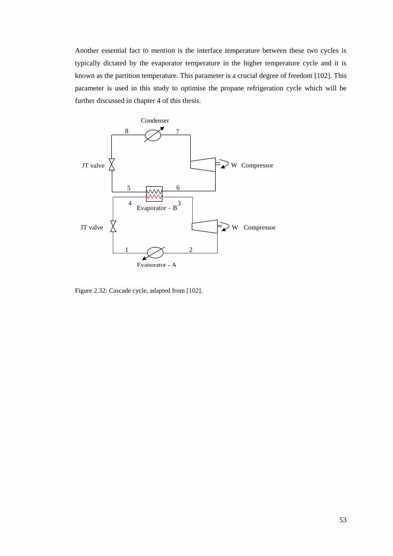
53
Another essential fact to mention is the interface temperature between these two cycles is
typically dictated by the evaporator temperature in the higher temperature cycle and it is
known as the partition temperature. This parameter is a crucial degree of freedom [102]. This
parameter is used in this study to optimise the propane refrigeration cycle which will be
further discussed in chapter 4 of this thesis.
Figure 2.32: Cascade cycle, adapted from [102].
5 6
1 2
3 4
7 8
Condenser
Compressor JT valve
Evaporator – B
(cascade condenser)
Evaporator - A
Compressor JT valve
W
W

54
Figure 2.33: Pressure-enthalpy (P-H) diagram for the cascade cycle; adapted from [96].
Cascade cycle can also be configured as multistage compression and expansion as shown in
Figure 2.34. This unique configuration is operated in a similar manner as discussed
previously, however, two different refrigerants are utilised to cool the process stream over a
wide range of temperatures. The refrigerant streamlines are denoted with purple and black
colours which represent refrigerant A and B respectively. Both refrigerant A and B have
their own dedicated compressors. As shown in Figure 2.34, merging of stream 7 with stream
13 reduces the inlet temperature to the HP stage, hence reduces the overall power
consumption of the cascade cycle. The pressure-enthalpy (P-H) diagram of this configuration
is illustrated in Figure 2.35. As can be seen from Figure 2.35, from point 5 to 6, evaporator
B acts as a condenser to condense refrigerant A by absorbing its heat; it is then compressed
to higher pressure from point 6 to 7. The discharge stream 7 is then desuperheated through
merging with the overhead vapour stream 13. The degree of superheat of the merged stream
i.e. stream 8 is reduced, hence reducing the inlet temperature to HP stage. This reduces the
overall power consumption of the cascade cycle. This configuration is used as a basis in
this research study.
Two phase
envelope of
refrigerant - A
Evaporator – B
(cascade condenser) Compression
refrigerant – A
Evaporator - A
Condenser
2 1
3 4
5 6
7 8
Two phase
envelope of
refrigerant -B
Compression
refrigerant – B
P
H

55
Figure 2.34: Multistage compression and expansion of the cascade cycle (own research work).
2
JT
4
1
3
5 6
7
8
9 10
11
12
13
Refrigerant A
Compressor
Evaporator - A
JT
JT
Multistage compressor
(Refrigerant B)
Condenser
Separator
Evaporator - B
W

56
Figure 2.35: Pressure-enthalpy (P-H) diagram for multistage compression and expansion of the
cascade cycle (own research work).
From the above discussion, it indicates that the refrigeration cycle can be modified and
configured in many ways to reduce energy consumption. All the LNG processes that have
been discussed in section 2.2 and others which are not mentioned in this thesis are developed
by combining features of different refrigeration cycles. As refrigeration is the heart of the
liquefaction process, optimising its design and operation parameter will improve the overall
process efficiency. In this study, the refrigeration cycle of the cascade LNG process is
optimised through the design and operational parameters which will be discussed in
chapter 3 onwards.
10
13
Refrigerant – A
compression
Two phase
envelope of
refrigerant - A
Two phase
envelope of
refrigerant -B
Refrigerant – B
multistage compression
Superheated
vapour
Evaporator - B
9
12
11
Evaporator - A
Condenser
2
3 4
5 6
7 8
1
P
H

57
2.7.3 Refrigeration cycle performance
The performance of the refrigeration system is analysed by measuring the coefficient of
performance (COP) as illustrated in Figure 2.37 [102]. This parameter is defined as the ratio
of the total heat absorbed by the refrigerant from the process stream to the amount of
compressor power required by the system as expressed below:
COP = Q / W
(2.3)
where Q is the refrigerant duty (MW) and W is the compressor power (MW).
Figure 2.36: Measuring the coefficient of performance of a refrigeration cycle, adapted from [102].
The higher the value of COP, the more efficient is the refrigeration cycle. Usually, the COP
value is greater than 1 [104]. In this study, COP is one of the parameters used to analyse the
cascade LNG process efficiency. The COP value is also affected by the selection of the
refrigerant which will be explained in the next section.
Heat rejected to
Q W
P
H
Compressor power
Refrigeration duty

58
2.7.4 Selection criteria for a refrigerant
The choices of refrigerants vary according to their applications. Refrigerants that are used for
refrigeration and liquefaction cycles can be grouped based on their chemical compositions as
described below [30]:
a. Halocarbons - They are refrigerants based on organic compounds i.e. carbon chains
that are initially attached to hydrogen and then replaced with one or more of
halogens such as chlorine, bromine and fluorine.
b. Inorganic compounds such as ammonia and carbon dioxide.
c. Hydrocarbons such as ethane, ethylene, propylene, propane and others which are
suitable as refrigerants and have been applied widely in the petroleum and
petrochemical industries.
d. Cryogenic gases have a very low triple point and normal boiling temperatures;
below -153oC and they are mainly used for cryogenic applications. These
refrigerants are methane, air, oxygen, nitrogen, helium and others.
For LNG plants, the selection of the right refrigerant depends on the type of LNG process;
whether it utilises either pure, MR or combination of both, its cooling range because natural
gas need to be liquefied from ambient temperature to -161oC, availability, the effect of
refrigerant on the COP, thermophysical properties such as the freezing point and latent heat
of vaporisation, evaporator pressure, refrigerant phase envelope, their compliance with
health, safety and environmental regulation and other general considerations [102, 105, 106].
Some of the thermophysical properties and other factors that affect the selection of
refrigerants are described below:
1. Freezing point
At a given evaporator pressure, the resultant operating temperature of a refrigerant
should be well above its freezing temperature to ensure smooth operation by
preventing any formation of solid refrigerant. The physical properties of some
common refrigerants that are used in the refrigeration cycle is presented in Table 2.3
[102].

59
Table 2.3: Physical properties of some common refrigerants at atmospheric pressure [93, 102, 107,
108].
Refrigerant Freezing
point,
Tf (oC)
Boiling
point,
Tb (oC)
Critical
temperature,
Tc (oC)
Critical
pressure, Pc
(bar)
Latent heat of
vaporisation,
hfg (kJ/kg)
Ammonia (NH3)
Ethylene (C2H4)
Ethane (C2H6)
Methane (CH4)
Propane (C3H8)
Propylene (C3H6)
Nitrogen (N2)
Carbon dioxide (CO2)
-78
-169
-183
-182
-182
-185
-210
< -78.5
-33
-104
-89
-161
-42
-48
-196
> -78.5
132.3
9.2
32.2
-82
97
92.4
-147
30.98
113
50.4
48.7
46.4
42.5
46.7
33.9
73.8
1, 370
482.5
489.7
510.4
426.1
439.5
198.6
349.5a a Given at -56oC.
2. Latent heat of vaporisation
The latent heat of a refrigerant should be as high as possible because evaporation of
liquid refrigerant is the only way that determines the amount of cooling and not the
vapour [105]. Having a refrigerant with a high latent heat content will not only
reduce the overall refrigerant flow rate across the cycle but also the power
consumption [102]. Thus, the COP of the refrigeration cycle will increase.
Another important point to mention is to ensure that the refrigerant temperature is
below the critical temperature as shown in the phase diagram in Figure 2.37 [102].
This is because when the refrigerant temperature increases, the latent heat of
vaporisation decreases as the critical point is reached. As can be seen from Figure
2.37 (a) to Figure 2.37 (b), as the condenser temperature reaches close to the critical
temperature, a significant amount of heat is removed through desuperheating via the
condenser. This causes an increase in the heat transfer area of the condenser as the
average heat rejection temperature exceeded [102]. In addition, the COP of the
refrigeration cycle also reduces as more power is required. Therefore, it is feasible to
operate the evaporator and condenser temperatures below the critical temperature to
ensure high latent heat of vaporisation.

60
Figure 2.37: Selection of refrigerant based on a critical point, adapted from [102].
Besides, the relationship between latent heat of vaporisation and temperature can be
described using the Watson equation [109] as expressed below:
∆ HVAP2
∆ HVAP1= (
TC − T2
TC − T1 )
0.38
(2.4)
where ∆ HVAP1 and ∆ HVAP2 represent the latent heat of vaporisation at temperature
T1 and T2 correspondingly, T1, T2 are temperatures in K and TC is the critical
temperature in K.
Equation (2.4) is rewritten where ∆ HVAP1 is replaced with ∆ HVAP, NBP, T1 is replaced
TNBT and T2 is replaced with temperature, T [102]:
∆ HVAP
∆ HVAP,NBP= (
TC − T
TC − TNBT )
0.38
(2.5)
where ∆ HVAP, NBP is the latent heat of vaporisation at normal boiling point and TNBP
is the temperature at normal boiling point. The ratio of latent heat of vaporisation is
denoted with λ, hence the equation becomes:
λ = ( TC − T
TC − TNBP )
0.38
(2.6)
Evaporator
Condenser
Evaporator
Condenser
(a) (b)
T
S
Critical point T
S
Critical point
Condenser
approaching
critical point

61
Rearranging equation (2.5) gives:
T = TC − λ2.63 (TC − TNBP)
(2.7)
From equation (2.6), given the corresponding normal boiling point and critical
temperature of a refrigerant, the maximum operating temperature of refrigerant can
be fixed if the minimum value of λ is stated. The conservatives value of λ is between
60 to 70% and 50% may be suitable for many other applications [102].
3. Evaporator pressure
As shown in Figure 2.38 [102], the evaporator pressure should be above the
atmospheric pressure to prevent any air ingress into the cycle that may cause safety
and performance issue.
Figure 2.38: Operating pressure of an evaporator [102].
4. Refrigerant phase envelope
Another aspect that affects the selection of a refrigerant is the saturation vapour line
(SVL) of the refrigerant in the phase envelope as shown in Figure 2.39 [102]. Moving
from Figure 2.39 (a) to Figure 2.39 (b), the saturation line becomes steeper. This causes
a reduction in the amount of desuperheating of the refrigerant with respect to
condensation. Thus, the heat transfer area of the condenser also decreases as the normal
heat rejection load reduces [102]. Additionally, the steep saturation line also increases
the COP as less power is required [102].
1 atm
Evaporator
P
H
Condenser

62
(a) (b)
Figure 2.39: Refrigerant phase envelope-saturation vapour line (SVL), adapted from [102].
5. General considerations
Some other general considerations which is required while selecting a refrigerant are as
follows; the refrigerant should be nontoxic, non-flammable, noncorrosive, free of water,
have low or no impact on the ozone depletion and global warming, low viscosity and
low surface tension is preferred, it has high refrigerant capacity (i.e. latent heat) and low
power requirement, high oil solubility and low freezing point and has a high saturation
pressure [102, 105, 110]. It is desirable if the refrigerant is readily available from the
process because introducing a new refrigerant will add to the cost of the plants such as
new storage requirements. Moreover, the new refrigerant needs to comply with the
safety and environmental standards [102]. Meanwhile, the data related to toxicity and
flammability of refrigerants can be obtained from the American Society of Heating,
Refrigerating and Air-Conditioning Engineers (ASHRAE) standard 15. This standard
serves the fundamental mechanical safety code for air conditioning and refrigeration
equipment in the US [105].
T
S
T
S
Saturated vapour line (SVL)
Steeper

63
Based on the above discussion, the selection criteria for a refrigerant is a crucial process to
ensure safe operation plus its effect on the refrigeration cycle performance (COP) [106].
Moreover, the refrigerants that were selected will also be based on the desired operating
temperature ranges and the cooling temperature of the process streams [26]. In this study, the
cascade LNG process utilises propane-ethylene-methane (C3H8–C2H4–CH4) refrigerants for
its refrigeration cycles. The combination of these pairs was chosen because the refrigerants
such as propane and methane are readily available from the plant, proven technology, fulfil
the desired operating cooling range for pre-cooling, liquefaction and sub-cooling which are
from ambient temperature to -40oC, -40oC to -100oC and -100oC to 153oC respectively.
Besides, the combination of these pairs of refrigerants for cascade cycle gives the highest
COP based on the study done by Yoon, Choi [106].
2.7.5 LNG higher heating value (HHV)
In LNG custody transfer, the LNG is sold based on its higher heating value (HHV). The
HHV (gross HHV) is defined as the heat released by the complete combustion in the air for a
specified amount of gas measured at a specified reference pressure and temperature where
the water produced is in liquid formed. LNG consists of more than 40% of HHV compared
to other liquid fuels obtained from chemical conversion of natural gas [111]. Meeting the
LNG HHV is one of the most critical requirements for any LNG plant as it is used for the
Sale and Purchase agreements (SPA), gas interchangeability and for plant performance
guarantee.
A comprehensive discussion for HHV measurements, inclusive of the correction with respect
to the ideal gas values to the real gas state which uses compressibility factor (z) can be found
in GPA-2172-96 standard [96], (Gas Processors Association, GPA, 1996). The HHV of the
pure components is presented in Table 2.4 [96]. In this study, two distinct integrated
LNG/NGL designs are proposed to meet the LNG HHV requirement set for the cascade
LNG process. This will be further discussed in chapter 5.

64
Table 2.4: Higher heating value of pure components [96].
Components Higher heating value (Btu/Scf)
Helium (He) 0
Nitrogen (N2) 0
Carbon dioxide (CO2) 0
Hydrogen sulphide (H2S) 637.1
Methane (CH4) 1010.0
Ethane (C2H6) 1769.7
Propane (C3H8) 2516.2
Butanes as isobutane 3252.0
Pentanes and heavier as hexane 4756.0
Note: For LNG HHV, the H2S HHV is not included as its removal limit prior to liquefaction
is 4 ppmv as mentioned previously in section 1.2.
2.8 Energy and exergy analyses
As discussed in chapter 1, section 1.5 and chapter 2, section 2.5.1, energy and exergy
analyses will be used as an optimisation tool to evaluate the process efficiency of the cascade
LNG process. The term thermodynamics efficiency or process efficiency will be
interchangeably used in this thesis. As explained in chapter 1, section 1.5, these methods are
used to overcome the limitations of the numerical optimisation methods. Identifying and
analysing the thermodynamics properties such as enthalpy and entropy of each process
stream is crucial as it provides a better understanding of the changes occurring within the
process. Moreover, the process engineer can utilise this valuable information for improving
the process from the equipment and process design point of view. In this section, the details
about the energy and exergy analyses will be explained.
2.8.1 Background of energy and exergy analyses
Energy and exergy analyses are derived from the first and second law of thermodynamics.
The first law of thermodynamics provides the theoretical basic analysis of energy. Its main
emphasis is on the conservation of energy principle; during a reaction, the amount of energy
remains constant when it changes from one form to another. The thermodynamic property
that is used to calculate the quantity of energy is enthalpy. The thermodynamic efficiency
and energy consumption of the overall cascade LNG process is determined through energy
analysis by measuring its two quantitative parameters namely the coefficient of performance
(COP) and specific power (SP). COP is the standard criterion used not only to measure the
refrigeration cycle performance as explained in section 2.7.3 but also for evaluating the
overall efficiency of the cryogenic process [53].

65
The definition of COP and its equation are described in section 2.7.3 and equation (2.3)
respectively. Whereas, SP is defined as the total power required by the system per unit mass
flow rate of LNG produced. SP is expressed as below:
SP = Σ Wreq
ṁLNG
(2.8)
where Σ Wreq is the total compressor power required (MW) and ṁLNG is the quantity of LNG
produced (tonne/h).
However, energy analysis alone is insufficient to examine and evaluate the internal
thermodynamic efficiency of a process with regards to its components. This is because it
only indicates the overall thermodynamic efficiency and does not give any insight
information about the sources and locations of irreversibilities that occur within the process
and due to unit operation. For instance, all LNG processes that have been applied in the LNG
plants are based on real refrigeration cycles that give some sort of irreversibilities. These
irreversibilities are originated due to several reasons such as friction, unrestrained expansion
of gas or liquid to a lower pressure in the expander or throttling valve, compression of gas to
a higher pressure in the compressor, mixing of matter at different compositions or states and
heat transfer across finite temperature difference in the evaporator and in the condenser [30,
55, 93]. Besides, as explained in section 2.5.1, the first law solely evaluates the quantity of
energy and not the quality [93]. From thermodynamic perspectives, the quality of energy
here means the capacity for producing work [95]. Therefore, to analyse the quality of energy
and to obtain the sources and locations of energy degradation, the second law of
thermodynamic which is exergy is required.
According to Rant [112], the term exergy is derived from Greek and it is defined as ‘ex’
means out and ‘erg’ means work. Exergy (Ex) is defined as the maximum magnitude of work
that can be achieved by a system when the system components are brought into a
thermodynamic equilibrium state with its environment in a hypothetical reversible process
[95, 113]. Though all processes are irreversible, engineers are keen to use the reversible
process concept. This is because when a system approaches a reversible state, the amount of
work required will be less by the work-consuming devices such as compressors, pumps and
fans. Whereas more work is generated by the work-delivering device such as turbines work
[93].

66
There are four main types of exergy that may involve in an energy conversion process
namely kinetic exergy, potential exergy, chemical exergy and physical exergy. Kinetic
exergy is referring to the kinetic energy where the velocity of the components relative to the
surface of the earth is measured [95]. Potential exergy is like the potential energy measured
based on the energy kept within the components at various levels of the surface of the earth.
Whereas, chemical exergy is evaluated with respect to exergy of the components related to
the departure of the chemical composition of a system from that environment [94]. While
physical exergy is associated with work produced when the system components change from
initial state to final state in a hypothetical reversible process with respect to the temperature,
To and pressure, Po of the environment. Hence, the exergy can be expressed as:
Ex = Ek + Ep + Echem + Ephys
(2.9)
where Ek, Ep, Echem and Ephys are kinetic exergy, potential exergy, chemical exergy and
physical exergy respectively.
In this study, the cascade LNG process only applies to physical exergy because the
liquefaction of natural gas process has more impact due to temperature and pressure based
exergy while the effect of mechanical exergy such as Ek and Ep is not significant. Besides,
the process also does not involve any chemical mixing, reactions and separation. Thus, Ek, Ep
and Echem terms are ignored from the exergy calculations [114]. Ignoring these terms, the
flow of physical exergy at equilibrium state with the environment is calculated as below:
Ex = (Ho − Hi) − Ta (So − Si)
(2.10)
where Ta is the ambient temperature in K, Ho and So represent the enthalpy and entropy
respectively of outlet streams while Hi and Si represent the enthalpy and entropy of the inlet
streams. The unit of enthalpy is in MJ/kg while entropy is in MJ/kg K. Exergy can be
delivered in three modes; exergy transfer accompanying with work, exergy transfer due to
heat transfer and exergy transfer related to mass entering and leaving a system [93, 94].
Equation (2.10) is a simplified form of exergy balance for a control volume system where no
exergy related to work, heat transfer and mass entering and leaving the system are
considered. This equation is also considered as an adiabatic and where no work is done by
the system or by the surroundings.

67
The exergy analysis consists of two main quantitative parameters which are the exergy loss
or lost work and exergy efficiency. To identify and locate the irreversibilities that occur
within a process and unit operation, the exergy loss that is contributed by each unit operation
is calculated. The expressions of exergy loss rate for the unit operation such as LNG heat
exchanger, compressor, valve, mixer, air cooler and pump are shown in Table 2.5 [30].
Meanwhile, the exergy efficiency is used to assess the usefulness of energy utilisation of the
liquefaction system and it is determined after obtaining the total exergy loss exhibited by
each unit operation. The exergy efficiency (ηex) is defined as the ratio of the difference
between the actual power supplied and the total exergy loss dissipated by the unit operation
to the actual power supplied by the system [30] and is expressed as:
ηex
= 1 ‒ (Σ exergy loss of each unit operation
actual power supplied)
(2.11)

68
Table 2.5: Exergy loss expression for unit operation, adapted from [30].
________________________________________________________________________________
Unit operation Inlet and outlet streams Exergy loss expressions
_________________________________________________________________________________________
Pump ĖxPump, loss= ṁ (ex1- ex2)- Ẇin
where ‘i’ is referring to various components at inlet and outlet streams of the LNG heat
exchanger, ṁ, ṁ1, ṁ2, and ṁ3 are the mass flow rates of respective streams in kg/s, ṁa is the
mass flow rate of air in kg/s, ex is the specific exergy in MJ/kg for the corresponding stream,
To is the environment temperature in K, S is the entropy in MJ/kg K, h is the enthalpy in
MJ/kg and Ẇ is the power in MW.
ĖxHX, loss = ∑ ṁi,ini exi,in- ∑ ṁi,outi exi,out LNG heat
exchanger
Compressor ĖxCOMP, loss = ṁ (ex1 - ex2) - Ẇin
1 2 Valves ĖxV, loss = ṁTo (S2 - S1), h1=h2
Mixer
Separat
or Air cooler
Air
coolers
ĖxMIX , loss= ṁ1ex1+ ṁ2ex2 - ṁ3ex3
2
Airin
1
Airout
ĖxAC, loss = (ṁ1ex1+ṁaexa)in – (ṁ2ex2+ṁaexa)out
Win
1
2
Win
1 2
C3out
C2in
NGout
C1out
C2out
C1in
NGin
C3in
1
2
3

69
2.8.2 Benefits of using energy and exergy analyses
The benefits of using energy and exergy analyses in optimising and evaluating the cascade
liquefaction process have many folds. For instance, by analysing the COP and SP, it gives an
idea about the maximum power required to achieve the desired LNG capacity and the overall
efficiency of the process. Whereas, through the computation of exergy loss and exergy
efficiency, various information can be obtained such as the location, reason and actual
magnitude of energy waste [53, 94]. Moreover, it also provides valuable measures of true
effectiveness and performance of an energy system from the thermodynamic context which
gives the direction for potential improvements [26, 53, 94]. Besides, through the calculation
of exergy loss of individual components and exergy efficiency, it gives better evaluation
compared with more other calculated efficiencies such as thermal efficiency of a power
plant, compressor or turbine isentropic efficiency and heat exchanger effectiveness as it is
based on the first and second law of thermodynamics [94].
Once the energy and exergy analyses are computed, this information is utilised to optimise
the thermodynamic efficiency of the cascade process by making the necessary adjustment to
the design and operating parameters. Many studies have used this approach to optimise the
LNG processes which will be discussed in the next section.
2.8.3 Application of energy and exergy analyses in LNG processes
Energy and exergy analyses have been widely used to optimise the LNG processes. Kanoglu
[51] investigated the performance of multistage cascade refrigeration cycle using energy and
exergy analyses by evaluating the COP, exergy destruction (exergy loss) and exergetic
efficiency. Based on his analyses, it was found that to obtain the minimum power in the
cascade cycle, it hinges on the properties of the inlet and outlet natural gas stream and the
power increases with decreasing in the liquefaction temperature. Kanoglu also suggested that
this method can be used for design, optimisation and performance evaluation of actual
liquefaction LNG plants utilising cascade process [51]. This approach has also been used by
Remeljej and Hoadley [54] for evaluating four different LNG processes suitable for small-
scale capacity.
Meanwhile, Mehrpooya, Jarrahian [50] applied this method to analyse the behaviour of
propane refrigeration cycle used in the NGL plants. It was found that the increase in the
pressure drop of evaporators causes a decrease in the COP and exergy efficiency. Cipolato,
Lirani [56] further optimised the multistage cascade refrigeration cycle from Kanoglu [51]
using exergetic analysis by analysing the effect of pressure at six different streams. Based on
the results, it indicates that the exergy loss rate was reduced by 48% compared to the base
case.

70
Vatani, Mehrpooya [55] reviewed the performance of five existing liquefaction processes
namely single mixed refrigerant (SMR) by Linde, SMR by APCI, C3MR by Linde, DMR by
APCI and MFC by Statoil/Linde. Energy and exergy analyses methods were used to measure
the performance of these processes. Results showed that the MFC has less energy
consumption, highest COP and exergy efficiency compared to the other processes. Lastly,
this technique is also commonly used to optimise and evaluate the efficiency of power plants
as discussed by the following references [115-118]. Based on the above discussion, it
indicated that this approach has been considered as a reliable and powerful tool for design,
optimisation and performance evaluation [51] not only for LNG processes but also by other
energy conversion systems.
2.9 Optimisation of LNG processes
The optimisation of the LNG plant is an important research area as previously mentioned in
Chapter 1, section 1.4. Other main drivers to optimise the LNG plants are such as significant
growth in LNG usage in various sectors, to minimise the GHG emission, minimise energy
consumption as well as the cost with prime focus on large scale LNG plants. Optimisation of
LNG plants is often measured based on improvements made in the process efficiency. An
LNG plant is said to be efficient when it has high reliability and high LNG production rate,
low energy consumption and low cost as well as when product quality is maintained. There
is a large number of studies have been performed that discussed the optimisation of LNG
processes from various aspects. In this section, the optimisation of LNG processes will be
discussed in three different areas which are the pre-cooling, liquefaction integrated with
NGL recovery process and standalone NGL process.
2.9.1 Pre-cooling cycle optimisation
As described in section 2.2 (Table 2.2), all the proven and newly invented LNG processes
have employed pre-cooling cycles. Only single mixed refrigerant (SMR) process do not use
any pre-cooling cycle because the natural gas is directly cooled to -161oC using a single
mixed refrigerant composition. This process is not discussed in this thesis as it is only
suitable for small scale LNG plants [54, 119, 120]. The pre-cooling cycle is the first cycle in
any liquefaction process which eradicates the heat from natural gas stream and other
refrigerants to a temperature approximately between -30oC to -55oC [53] based on the type of
refrigerant or based on various combination of MR the process used. This pre-cooling
temperature range depends on the type of LNG technology applied. The pre-cooling cycle
also provides cooling for the pre-cooler, cold box (cryogenic section) and fractionation
section of an LNG plant [31].
71
Due to the substantial progress in the liquefaction technologies, the pre-cooling cycle can
employ either pure (single) refrigerant or mixed refrigerant. According to Castillo, Majzoub
Dahouk [121], 95% of the existing LNG plants have the pre-cooling cycle installed in their
LNG process and 85% of them have utilised propane in their pre-cooling cycle instead of the
mixed refrigerant. The pre-cooling cycle consumes more than 50% of the total power of an
LNG process based on the data obtained from the following references [31, 46, 104]. Many
studies have been done that discussed various ways to optimise the efficiency of the pre-
cooling cycle. Castillo and Dorao [122] studied the appropriate refrigerants choice for the
pre-cooling cycle by analysing the effect of methane, ethane and propane and a mixture of
these components on the compressor power, refrigerant effect, refrigerants flow rates,
coefficient of performance (COP) and heat exchanger duty and UA using Linde-Hampson
process. It was found that propane refrigerant consumed the least amount of power, has a
higher specific refrigerant effect (i.e. high capability to remove heat), low molar flow rates,
high COP and required less duty and low UA compared to other refrigerants for the same
process conditions which makes it the preferred refrigerant for the pre-cooling cycle.
Paradowski, Bamba [46] analysed the propane pre-cooling temperature of LP stage (-34oC to
-31oC) and its compressor speed (3000 to 4670 rpm) for C3MR process that could
debottleneck the existing LNG plant capacity to 5.5 MTPA as well as improve the process
efficiency. It was found that the optimal propane pre-cooling temperature for LP stage is -
31oC and the required compressor speed is 3600 rpm to meet this new LNG production
capacity. Ransbarger [123] compared between the three-stage and four-stage propane
refrigeration cycle of cascade LNG process with the aim to optimise the refrigeration levels.
Results showed that adding the fourth stage in the propane cycle will only reduce the
required power by 1%, thus the economics did not justify the increased in the capital cost
due to the additional stage.

72
Majzoub [124] studied the effect of using only pure components (ethane and propane) and
mixed refrigerant (made up of ethane and propane) for various pre-cooling cycle
configurations which are suitable for both cold (6oC) and hot (25oC) climate conditions for
C3MR and MFC LNG processes. He analysed the proposed pre-cooling cycle configurations
by computing the following variables such as the COP, compression power, pressure ratio,
inlet volumetric flow of compressor and heat exchanger UA (product of overall heat transfer
coefficient and heat exchanger area). The results showed that utilising only propane in the
pre-cooling cycle gives the lowest compression power, heat exchanger UA, intermediate
inlet volumetric flowrate and highest COP compared to mixed refrigerants for both climates
conditions. Besides, a three-stage propane pre-cooled cycle was found to be a better option
from an energy efficiency perspective compared to a two-stage mixed refrigerant (ethane and
propane) cycle for both climate conditions. Majzoub also suggested a novel and efficient
configuration for MFC whereby propane is used instead of mixed refrigerant for the pre-
cooling cycle.
Fathalla [125] investigated the performance of a four-stage propane pre-cooling cycle for
C3MR process at Segas LNG plant in Egypt during hot climate conditions. The temperatures
range from 25oC to 35oC. He studied the effect of routing the discharge of propane
compressor directly to the recycle cooler before entering the propane condenser and analysed
the effect of altering the propane refrigerant composition by adding methane and ethane
components. Results deduced that with the aid of the recycle cooler during the hot climate
conditions, full condensation of propane was achieved after the propane condenser. Further,
altering the propane refrigerant composition by adding the lighter components give the
highest power consumption and air cooler duty across the propane condenser and lowest UA.
The compressor power increased due to a rise in the lighter components while the air cooler
duty increased because of the large condensing duty required to condense the lighter
components. Hence, propane is considered as the most suitable refrigerant for the pre-
cooling cycle.
Meanwhile, the design of the pre-cooling cycle has been evolved in recent decades. In this
context, various studies have been presented that were related to the optimisation of the
efficiency of the propane cycle with respect to its design configuration. Mortazavi, Somers
[31] suggested the replacement of the conventional expansion valves in the C3MR process
with expanders to improve the liquefaction efficiency. Results showed that about 2.68 MW
reduction in the compressor power, 3.82 MW recovery of expansion work and 1.24%
increase in the LNG production can be achieved through this modification. Further, the
specific power was minimised by 7.07% by considering the deduction of the recovered
power from the total required power and 3.68% without considering it.

73
In another study, Mortazavi, Somers [126] optimised the energy efficiency of the C3MR
process by utilising the waste heat from a gas turbine powering the absorption chillers in the
propane cycle. They simulated eight options for the gas turbine waste heat utilisation using
Aspen Plus. Based on the simulation results, reduction of 21.32% was achieved in terms of
the compressor power and fuel consumption which obtained through replacement of the
evaporators at 22oC and 9oC. Also, condensing the propane at 14oC and using the absorption
chillers for inter-cooling of the mixed refrigerant cycle. Kalinowski, Hwang [127] proposed
the replacement of the propane chillers with an absorption refrigeration system in the LNG
recovery process. This refrigeration system utilised the waste heat from the electrical power
generating gas turbines. From this modification, it was found that from the 9 MW electricity
generated, 5.2 MW of waste heat was used for cooling purpose in the LNG plant and saved
1.9 MW of electricity usage. Therefore, having an energy-efficient refrigeration cycle will
improve the plant operation and provide economic benefits [57].
2.9.2 Gaps in the optimisation of the pre-cooling cycle
Table 2.6 presents the summary of the optimisation studies done for the pre-cooling cycle in
the open literature and highlights the process variables that were analysed. As can be seen
from Table 2.6, the optimisation of propane pre-cooling cycle in the previous literature was
mainly centred on its design such as varying the types of refrigerants used in this cycle i.e.
pure vs. MR, a number of refrigeration stages and replacing the conventional equipment of
the propane cycle with other equipment. Most of these studies have focused on optimisation
of MR based liquefaction processes but not many studies are available for the cascade
process. Further, very scant studies are obtainable that discuss optimisation from an
operational perspective. In this research work, a three-stage propane cycle is optimised by
altering the operating conditions of the propane evaporator. A three-stage propane pre-
cooling cycle configuration is chosen for this research work as it was found to be the most
energy efficient and economical option as described in the following references [121, 123,
124]. Detailed work will be further discussed in Chapter 4 of this thesis.

74
Table 2.6: Summary of pre-cooling cycle optimisation studies in the open literature.
Year Reference Simulation
software
Optimisation studies
2013 L. Castillo
and C.A.
Dorao
Aspen HYSYS, Compared using of pure propane and mixed refrigerant
in the pre-cooling cycle for Linde-Hampson process.
Analysed the compressor power, refrigerant effect and
refrigerants flow rates, coefficient of performance
(COP) and heat exchanger duty and UA.
2004 Paradowski,
et al.
Not stated Analysed propane pre-cooling temperature of LP stage
and its compressor speed for 5.5 MTPA C3MR process
2007 Weldon
Ransbarger
Not stated Compared three-stage and four-stage propane
refrigeration cycle for cascade LNG. Analysed the
amount of energy saving.
2012 Majzoub Aspen HYSYS,
Peng Robinson
Compared to the use of pure components and mixed
refrigerant in the pre-cooling cycle. Analysed the COP,
compression power, pressure ratio, inlet volumetric
flow of compressor and heat exchanger UA.
2013 Fathalla Aspen HYSYS Investigated the performance of a four-stage propane
pre-cooling cycle for C3MR process at Segas LNG
plant, Egypt during hot climate conditions. Studied the
effect of routing the discharge of propane compressor
directly to recycle cooler before entering the propane
condenser and analysed the effect of altering the
propane refrigerant composition.
2012 Mortazavi,
et al.
Aspen Plus Proposed replacement of expansion valves with
expanders in the C3MR process.
2010 Mortazavi,
et al.
Aspen Plus Optimise the energy efficiency of the C3MR process by
utilising the waste heat from the gas turbine to powered
absorption chillers in the propane cycle.
2009 Kalinowski
et al.
Not stated Proposed the replacement of the propane chillers with
an absorption refrigeration system in the LNG recovery
process. This refrigeration system utilised the waste
heat from the electrical power generating gas turbines.

75
2.9.3 Integrated LNG/NGL processing plant optimisation
In the earlier design of LNG plants, natural gas liquid (NGL) plants were built upstream of
the liquefaction plants and there was no integration between these two processing plants
[33]. Alternatively, as described in section 2.7.5, the LNG product is sold based on the HHV
specification. Therefore, to meet this criterion, the removal of heavier hydrocarbons or the
NGL unit is necessary for the LNG plant. According to Hudson, Wilkinson [32] having an
NGL unit in an LNG plant not only assist in meeting the HHV specification [40] but protect
the plant from having operational problems such as freezing of aromatics in the downstream
equipment (i.e. liquefaction unit) and the plant operation is less affected if changes in the
feed gas composition occurred. This is because the liquid recovery unit can maintain the
removal efficiency over a wide range of compositions. Besides, this integrated configuration
gives low specific power which means that there is more room to increase the train size for a
given driver selection.
On the other hand, in a standalone LNG plant, the required refrigerant such as propane is
obtained from the external cycles and separate heat exchangers, whereas in the integrated
LNG plant, the required refrigerant is obtained from joint refrigeration cycles and shared
devices [128]. In addition, there are other advantages of this integration such as a reduction
in the capital and operating cost of the plant [34], elimination of combined emissions of
carbon dioxide (CO2) and nitrogen oxides (NOx) and improvement of the overall
thermodynamic process efficiency [33, 34, 40]. In another study, NGL facilities have been
introduced at LNG receiving terminals to meet stringent HHV specifications set by the local
stakeholders [129].
The integrated LNG/NGL process has been considered as one of the simple and practical
ways to improve the process efficiency of the plants [26, 32, 34]. For instance, when the
liquefaction section is integrated with the NGL section, the energy requirement for
separation, condensation and sometimes cooling of these liquid products obtain power from
the liquefaction drivers [40]. As the demand of building larger and process efficient LNG
plants grow rapidly [40], many of the LNG process licensers such as Air Products (APCI),
ConocoPhillips (COP) and Shell have developed various integrated processes. For example,
ConocoPhillips had applied this integrated concept to three of the LNG plants that resulted in
about a 7% increase in the LNG production for the same required power [33]. Fluor
Technologies reported that 10% of energy saving has been obtained through integration of
LNG and NGL processes [130].

76
Various studies are available that discuss areas to optimise the integrated LNG/NGL plants.
Khan, Chaniago [131] studied three different NGL configurations namely the conventional
separation sequence (base case), direct sequence thermal coupling (TCDS) and dividing wall
distribution column (DWC) whereby they were integrated with Korea single mixed
refrigerant (KSMR) liquefaction process. The studied plant capacity was 2.5 MTPA and
suitable for offshore-based LNG plants. These configurations were investigated for their
energy efficiency, product recovery and purity. After the integration, the MR cycle was
optimised with the aim to minimise the compression energy requirement by changing its
composition and varying the pressure levels of the MR compressor. They used an in-house
knowledge-based optimisation method. The results showed the proposed KSMR liquefaction
process integrated with TCDS NGL configuration gain 9% reduction in the compression
energy requirement and SP compared to the base case.
Mehrpooya, Hossieni [128] applied energy and exergy analyses methods to minimise the
energy consumption and to obtain high ethane recovery for three novels integrated
LNG/NGL processes. DMR, C3MR and MFC liquefaction processes are used to supply the
required refrigeration for the process. The ethane recovery and the specific power (SP) are
optimised by varying the cold recycle flow rate and its temperature in the NGL column (T-
100). Recycle ratio is another important parameter that influences these results. From the
analyses, all the proposed configurations can recover ethane above 90% and the specific
power are between 0.35 to 0.38 kWh/kg LNG. This integration provides several benefits
such as elimination of compressor, multi-stream heat exchanger and reduction in the required
cold and hot utility.
Pillarella, Bronfenbrenner [42] optimised the efficiency of AP-X process by analysing the
effect of reducing the temperature approach of hot and cold streams in the propane
condenser. They also computed the exergy loss exhibited by the equipment in the process. It
was found that reducing the temperature approach not only improved the efficiency of the
main heat exchanger but also reduced the SP of the liquefaction process. This can be
achieved by increasing the heat exchanger surface area. However, when the minimum SP is
reached, a substantial increase in the heat exchanger area is observed, hence this indicates
that there is an economic evaluation required to obtain a feasible design. Further, the exergy
analysis results showed that the refrigerant compressors, air coolers and heat exchangers
attained the largest exergy losses, hence affect the efficiency. Exergy results are used to
make necessary adjustments on the process flow sheet and evaluate the process efficiency.

77
He and Ju [132] optimised a novel mixed refrigerant cycle (MRC) integrated with an NGL
process for a small-scale LNG plant using a genetic algorithm (GA) and exergy analysis.
They investigated the effect of MR composition and its pressure and the inlet pressures of
the demethaniser (De-C1) and De-C2 columns to reduce the energy consumption of the
process. However, they did not analyse the effect De-C2 column pressure on the process
parameters, irreversibility and efficiency. The results showed that about 9.64% and 11.68%
reduction in the energy consumption and refrigerant molar flow rate respectively can be
achieved compared to the base case. Further, the inlet pressure of De-C1 does affect the
energy consumption, reboiler and condenser duty, hence an optimal value of De-C1 should
be chosen to minimise the energy consumption. Conversely, the inlet pressure of De-C2
gives no significant effect on energy consumption and other process variables.
With respect to cascade liquefaction optimisation, Ransbarger [133] proposed four different
process configurations for an integrated LNG/NGL cascade process using propane, ethane
and methane open cycles. Though the description for these processes was given, however no
technical data on the process simulation were stated, hence no information on the amount of
energy consumption and other parameters are available which can be used as a reference for
future studies. Cipolato, Lirani [56] further optimised the multistage cascade liquefaction
process based on the work done by Kanoglu [51] and Filstead [134] using exergetic
optimisation approach. They simulated the process in Aspen HYSYS v. 3.2 and employed
Peng Robinson equation of state to obtain the thermodynamic properties of the process. They
studied the influence of pressure in six different locations in the propane, ethane and
methane cycles using a full factorial experimental planning. These pressures are located after
the compressor and expansion valves in for each cycle. The results showed that 48%
reduction in the exergy loss can be obtained by using the new set of operational data
compared with the base case.
Meanwhile, Yoon, Choi [104] compared three different cascade cycles that used different
combination sets of refrigerants namely carbon dioxide-ethylene-nitrogen cycle
(CO2–C2H6–N2), propane-ethylene-methane cycle (C3H8–C2H4–CH4) and carbon dioxide-
nitrogen cycle (CO2–N2). Results indicate that C3H8–C2H4–CH4 cycle gives the highest COP
and refrigeration capacity and lowest compressor power compared to other proposed cycles.
Furthermore, among the three liquefaction cycles, the total exergy loss of C3H8–C2H4–CH4
cycle was the lowest, followed by the liquefaction of CO2–C2H6–N2 cycle and CO2–N2 cycle.

78
Fahmy, Nabih [135] optimised the performance of Open Cycle Philips optimised cascade
process for the production of 4.24 MTPA LNG capacity through replacement of J-T valves
with liquid expanders. Firstly, they simulated the conventional process with J-T valves in
Aspen HYSYS v. 7. Later, the J-T valves were replaced with liquid expanders at various
locations in the propane, ethylene, methane cycles and upstream of heavy’s removal column.
It was found that by replacing the J-T valves with liquid expanders, about 5.8% power
saving, 92.81% thermal efficiency and a 7% rise in the LNG production can be achieved.
2.9.4 NGL process optimisation
With respect to optimisation of NGL process, Shin, Yoon [136] focused on improving the
energy consumption of NGL process by varying the type of feed gas (lean and rich) and a
number of stages of De-C1 column (10 and 30-stages) using exergy analysis method. Three
NGL processes were investigated namely the gas sub-cooled (GSP), recycle split vapour
(RSV) and cold residue reflux (CRR). It was found that the total energy usage and exergy
loss for GSP is the lowest for the majority of the case studies such as the lean feed gas (De-
C1 column with 10 stages) and rich feed gas (De-C1 column with 10 and 30-stages). In
contrary, GSP consumes the highest energy consumption and exergy loss for lean feed gas
case study (De-C1 column with 30-stages).
Lee, Long [137] proposed a new design for the NGL recovery process consisting of De-C1
column and a top dividing wall column (TDWC). This configuration is suitable for floating
LNG (FLNG) applications. TDWC is used to integrate the depropaniser (De-C3) and
debutaniser (De-C4) columns to improve energy efficiency and minimise the number of
columns in the NGL recovery process. The results indicate that by using TDWC, 35.09% of
refrigeration costs can be saved compared to the conventional process line up used in an
onshore integrated NGL recovery process. Further, the duties of propane condenser and
reboiler can be minimised by 21.42% and 11.79% respectively. With TDWC diameter of 1.5
m, the energy usage can be reduced by 15.36% relative to total annual cost (TAC) compared
to conventional NGL column sequence.

79
2.9.5 Gaps in the optimisation of the integrated LNG/NGL plants and NGL processes
Table 2.7 shows the summary of the optimisation studies conducted for integrated
LNG/NGL and standalone NGL recovery plants in the open literature and highlights the
process variables that were analysed. As can be seen from Table 2.7, most of the former
optimisation studies available for integrated LNG/NGL and NGL processing plants have
focused on the design and operation of MR based integrated liquefaction processes and
applicable for either small scale or offshore LNG plants.
For instance, some of the common optimisation parameters that were studied for the
integrated LNG/NGL plants are the MR composition, its pressure levels, lean vs. rich feed
gas, NGL column temperature and it recycle flow rate and inlet pressures of De-C1 and De-
C2 columns. As discussed earlier, for the cascade process, Ransbarger did not provide any
numerical data about the amount of energy consumption required for the proposed integrated
configurations. This could be due to the confidentiality issue and limitation on sharing the
ConocoPhillips technical data. As mentioned above, some areas that were studied to
optimise the NGL process are several types of feed gas, different sets of De-C1 column
stages and proposal of new NGL recovery design for FLNG application.
On the other hand, no studies are available that discuss the optimisation areas for the
integrated LNG/NGL cascade process for a large single train. For example, the effect of
different integrated LNG/NGL designs on the LNG HHV specification, process parameters,
the effect of De-C2 column pressure on the process performance and efficiency have not
been studied. Therefore, in this research work, 5 MTPA integrated LNG/NGL cascade
process is optimised to close these studies gaps.
The optimisation of the integrated cascade process is carried out in three steps. Firstly,
optimisation of the propane pre-cooling cycle as explained in section 2.9.2. Based on the
energy and exergy analyses results, optimal operating conditions of the pre-cooling cycle are
obtained. Next, using this optimal pre-cooling operating data, the cascade process is further
optimised by determining the optimal design for integrated ethylene refrigeration cycle with
NGL section. Lastly, the optimal integrated LNG/NGL design is selected and again further
optimised by manipulating the deethaniser (De-C2) column pressure. A detailed discussion
about these optimisation areas of cascade LNG process is covered in chapter 4, 5 and 6 of
this thesis.

80
Table 2.7: Summary of optimisation studies for integrated LNG/NGL processing plants and
standalone NGL recovery plant.
Year Reference Simulation
software and
EOS
Optimisation studies
2014 Khan et al. Aspen HYSYS,
Peng Robinson
and Lee Kestler
Studied three different NGL configurations integrated
with Korea single mixed refrigerant (KSMR)
liquefaction process suitable for the offshore based
LNG plant. Optimised the MR composition and its
compressor pressure levels.
2014 Mehrpooya
et al.
Recommend
Aspen Plus or
Aspen HYSYS,
Peng Robinson
Minimised the energy consumption and maximised
high ethane recovery for three novels integrated
LNG/NGL processes (DMR, C3MR, MFC) by varying
the cold recycle flow rate and its temperature in the
NGL column.
2005 Pillarella, et
al.
Not stated Studied the effect of minimising the temperature
approach in the propane condenser towards the heat
exchanger area and SP for AP-X process. Computed the
exergy loss of the process equipment.
2014 He and Ju Aspen HYSYS Optimised a novel MRC integrated with NGL for the
small-scale LNG plant. Analysed the effect of MR
composition and its pressures and De-C1 and De-C2
columns inlet pressures.
2008 Ransbarger Not stated Proposed four different process configurations for an
integrated LNG/NGL cascade process using propane,
ethane and methane open cycle. No numerical data are
available on the energy consumption required for these
configurations.
2012 Cipolato, et
al.
Aspen HYSYS
v. 3.2, Peng
Robinson
Studied the influence of pressure in six different
locations in the propane, ethane and methane cycles for
cascade process.
2014 Yoon, et al. Aspen HYSYS,
Peng Robinson
and Lee–
Kesler–Plocker
Compared C3H8–C2H4–CH4, CO2–C2H6–N2 and
CO2–N2 cascade cycles efficiencies and computed the
exergy loss of the process equipment.
2016 Fahmy, et al. Aspen
HYSYS v. 7
Studied the effect of replacing the J-T valves with
liquid expanders in the Open Cycle Phillips optimised
cascade process for the production of 4.24 MTPA
LNG.
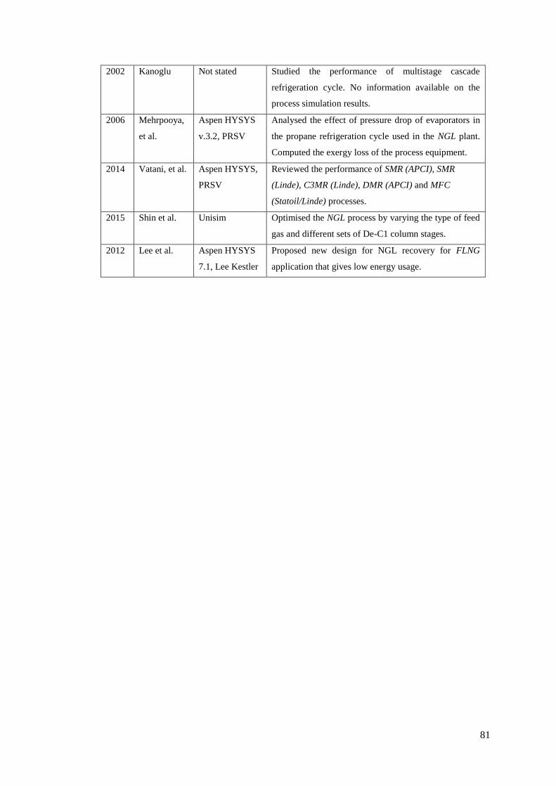
81
2002 Kanoglu Not stated Studied the performance of multistage cascade
refrigeration cycle. No information available on the
process simulation results.
2006 Mehrpooya,
et al.
Aspen HYSYS
v.3.2, PRSV
Analysed the effect of pressure drop of evaporators in
the propane refrigeration cycle used in the NGL plant.
Computed the exergy loss of the process equipment.
2014 Vatani, et al. Aspen HYSYS,
PRSV
Reviewed the performance of SMR (APCI), SMR
(Linde), C3MR (Linde), DMR (APCI) and MFC
(Statoil/Linde) processes.
2015 Shin et al. Unisim Optimised the NGL process by varying the type of feed
gas and different sets of De-C1 column stages.
2012 Lee et al. Aspen HYSYS
7.1, Lee Kestler
Proposed new design for NGL recovery for FLNG
application that gives low energy usage.

82
Chapter 3 Process modelling and simulation of Cascade LNG
process
3.1 Introduction
This chapter describes the basis of process modelling and simulation applied for cascade
LNG process for 5 MTPA production capacity. The cascade LNG process is first modelled
and simulated using the operational data obtained from the following literature [31, 46, 51,
54, 120, 122, 123, 125-127] and existing LNG plants located in the Southeast Asia region,
Australia, Gulf countries, Northern Asia and Africa. These plants are not disclosed because
of confidentiality issues. In this study, the cascade LNG process is simulated and optimised
in three steps. Firstly, a three-stage propane pre-cooling cycle is modelled and simulated.
The propane pre-cooling cycle is optimised, and the detail of this work is described in
Chapter 4. After optimisation of the propane cycle, two different configurations of the
ethylene refrigeration cycle integrated with the NGL section are compared to find the
optimum design. Based on the optimisation results, the optimum integrated design is
selected. Detail of this work is described in Chapter 5. Finally, the selected optimum
integrated cascade design is further optimised by manipulating the deethaniser (De-C2)
column pressure which will be discussed in Chapter 6. The modelling assumptions and
simulation constraints applied in all the three optimisation areas are explained in the next
section. Additionally, the simulation description, process simulation flow scheme, stream
properties and composition for each stream are also presented.
3.2 Simulation basis and modelling assumptions
The cascade LNG process is modelled and simulated in a steady state mode using Aspen
HYSYS (v.7.2, 2010). The pre-treatment unit was not modelled in this work as the main
emphasis is on the optimisation of the pre-cooling, liquefaction and NGL section.
Peng Robinson equation of state (EOS) is used to obtain the physiochemical properties of the
fluid [138]. The process simulator and EOS are prevalent for simulating the LNG and NGL
processes and have been confirmed in previous studies [31, 55, 60, 132, 139, 140]. The feed
gas conditions [53] and modelling assumptions applied in this study are summarised in Table
3.1. For all the research works, the same simulation basis and modelling assumptions are
applied.

83
Table 3.1: Feed gas condition and modelling assumptions.
Process parameters Condition
NG feed condition
Flow rate (kgmole h-1)
Pressure (kPa)
Temperature (oC)
41,700
7500
29
NG feed gas composition a[53]
Nitrogen
Methane
Ethane
Propane
i-Butane
n-Butane
i-Pentane
n-Pentane
mole fraction
0.0028
0.8974
0.0496
0.0343
0.0079
0.0073
0.0005
0.0002
Mechanical efficiency
Compressor polytropic efficiency [132]
Pump adiabatic efficiency
80 %
85 %
Pressure drops (kPa)
LNG HX
AC
20
30
Minimum temperature approach (MITA)
in HX
> 2 oC
Column hydraulicsb
Demethaniser (De-C1)
Operating pressure (kPa)
Number of theoretical stages
Deeethaniser (De-C2)
Operating pressure (kPa) [132]
Number of theoretical stages
3400
43
1800-2200
38
Ambient temperature (oC)
Air cooler exit temperature (oC)
Plant availability, days/year
27
49
330
a Feed gas composition and condition are taken after the treating section.
b The demethaniser and deethaniser theoretical stages are taken from a petrochemical plant located at Basrah,
Bagdad, Iraq [141].

84
3.3 Process simulation constraints
The following are the constraints applied in modelling the integrated cascade process:
1. The inlet temperature of all the compressors should be maintained above its dew
point temperature to prevent the ingress of liquid droplets. Compressor
discharge temperature should be below 120oC to safeguard its mechanical
components [142].
2. LNG higher heating value (HHV) requirement is 39.12 – 41.92 MJ/m3 (1,050 –
1,125 Btu/Scf)
3. The targeted LNG plant capacity is 5 MTPA (631,313 kg/h).
4. The minimum temperature approach (MITA) in the LNG heat exchanger is to be
assured above 2oC to avoid temperature cross.
3.4 Cascade LNG process simulation description
The process simulation flow scheme of cascade LNG process (base case) is shown in Figure
3.1 and Figure 3.2. The treated natural gas at 29oC and 75 bar enters the propane
refrigeration cycle and is cooled consecutively in three heat exchangers namely HXC3-1,
HXC3-2 and HXC3-3 to -25oC, -30oC and -40oC respectively. The propane also cools
methane and condenses ethylene refrigerants simultaneously along with natural gas. The
vaporised propane refrigerant is then compressed in three different stages (K-100 LP C3,
K-101 MP C3 and K-102 HP C3) to 18 bar. The compressed propane refrigerant is finally
condensed in a series of air coolers and expanded via CV-1.
The natural gas and methane refrigerant are then cooled by ethylene refrigerant to -55oC in
the first heat exchanger (HXC2-1). The cooled natural gas is then expanded via CV-6 and
then enters the demethaniser column (De-C1) at 34 bar. The De-C1 column is operated as a
total condenser. The bottom of De-C1 column (1_NGL) is expanded via CV-7 to 20 bar
before entering the deethaniser column (De-C2). The De-C2 column is operated as full
reflux. The De-C2 column bottom is sent to the depropaniser column (De-C3) while the
overhead of De-C2 column (10_NG) is compressed to 33.8 bar. The overhead of De-C1
column (9_NG) and De-C2 column (10_NG) are mixed together before being cooled by the
second ethylene heat exchanger (HXC2-2) to -95oC. Whereas methane refrigerant finally
condensed after been cooled by the second ethylene heat exchanger. The vaporised ethylene
refrigerant is then compressed in two stages (K-100 LP C2, K-101 MP C2) to 25 bar. The
compressed ethylene is then cooled in a series of air coolers and condensed by propane
refrigerant before finally reduced in pressure via CV-4.

85
The natural gas is further cooled by methane refrigerant to -115oC, -140oC and -152oC in
three heat exchangers (HXC1-1, HXC1-2 and HXC1-3) respectively. The liquefied natural
gas is then expanded to 1.01 bar via CV-11 before entering the LNG tank. Meanwhile, the
vaporised methane refrigerant is compressed in three compression stages (K-100 LP C1, K-
101 MP C1 and K-102 HP C1) to 36.5 bar. The superheated methane refrigerant is then
cooled by the propane refrigerant and condensed by ethylene refrigerant before been
expanded via CV-8. The details stream properties are presented in Table 3.2 and Table 3.3
while the composition for each stream is presented in Table 3.4, Table 3.5 and Table 3.6.

86
Figure 3.1: Aspen HYSYS process simulation flow scheme for the cascade LNG process (base case) – propane and partly ethylene refrigeration cycles.

87
Figure 3.2: Aspen HYSYS process simulation flow scheme for the cascade LNG process (base case) – ethylene and methane refrigeration cycles.

88
Table 3.2: Base case stream properties (a)

89
Table 3.3: Base case stream properties (b)

90
Table 3.4: Base case stream composition (a).

91
Table 3.5: Base case stream composition (b).

92
Table 3.6: Base case stream composition (c).

93
3.5 Optimisation framework of Cascade LNG process
After the Cascade LNG process is modelled and simulated in Aspen HYSYS v. 7.2, a
calculation spreadsheet has been developed within this software. This spreadsheet contained
detailed thermodynamics information for each refrigeration cycle such as the inlet and outlet
enthalpies and entropies for all the unit operations (compressors, LNG heat exchangers,
valves, mixers and air coolers), LNG heat exchanger duty, UA, temperature approach, log-
mean temperature difference (LMTD) and heat balance. Also, the energy and exergy
equations have been developed within the spreadsheet. These thermodynamics data and
equations are used to calculate the efficiency of the cascade process. This information is then
transferred to Microsoft Excel for further analysis and the optimisation results are presented
in the graphical form. Based on the energy and exergy analyses results, the cascade process
is further optimised. This approach is in agreement with the optimisation work done by
Cipolato, Lirani [56], Kanoglu [51], Mokhatab, Mark [30] and Vatani, Mehrpooya [55].
Details of the optimisation framework for the propane pre-cooling cycle, integrated ethylene
refrigeration cycle with NGL section and effect of De-C2 column are discussed in Chapter 4,
Chapter 5 and Chapter 6 respectively in the thesis.
3.6 Simulation model verification
The model verification for propane pre-cooling cycle and integrated LNG/NGL processes
are discussed below.
3.6.1 Model verification (propane pre-cooling cycle)
The propane pre-cooling cycle simulation model is verified by performing the heat and mass
balance. The heat balance across LNG heat exchanger is expressed as:
Qprocess (NG+C1+C2) = Qrefrigerant (C3)
(3.1)
(QNG + QC1 + QC2) HXC3-1/2/3 = (QC3) HXC3-1/2/3
(3.2)
where QNG, QC1, QC2 and QC3 are the duty of natural gas stream, methane, ethylene and
propane respectively in MW. The overall heat balance for case 1 and case 6 are detailed in
Appendix A.
The overall mass balance of the process is shown in Figure 3.3 and expressed as:

94
NGfeed = LNGvapour + LNGproduct + De-C2 bottom product + ethane
(3.3)
where NGfeed is the inlet feed flow rate of the natural gas and LNGvapour, LNGproduct,
De-C2 bottom product and ethane are the outlet streams in kgmole/h.
Figure 3.3: Overall mass balance of cascade LNG process.
3.6.2 Model verification for integrated LNG/NGL processes
The integrated LNG/NGL designs are verified by performing the heat and mass balance. The
heat balance across LNG heat exchanger is expressed as:
Qprocess (NG+C1) = Qrefrigerant (C2)
(3.4)
(QNG + QC1) HX-C2-1/2 = (QC2) HX-C2-1/2
(3.5)
where QNG, QC1, and QC2 are the duty of natural gas, methane and ethylene streams
respectively in MW and HX-C2-1/2 are the ethylene heat exchangers. The overall heat
balance for configuration 1 and configuration 2 are detailed in Appendix A. The overall mass
balance of the process is calculated using equation (3.3)
Cascade LNG process NGfeed
LNGvapour and
LNGproduct
De-C2 bottom product and
ethane

95
Chapter 4 Process efficiency optimisation of propane pre-cooling
cycle
4.1 Background
In this chapter, the process efficiency of a three-stage propane pre-cooling cycle is optimised
by determining the optimal operating conditions of the propane evaporator that gives
maximum energy reduction and highest process efficiency. Detailed background and
significance of this research area have been discussed in Chapter 2 (section 2.9.1 and 2.9.2).
Six case studies were presented with different operating conditions applied to the propane
evaporator at each stage. The process efficiency is evaluated by analysing the quantitative
parameters of energy and exergy analyses for all the case studies that were presented. The
content of this chapter has been published in the Journal of Natural Gas Science and
Engineering [53].
4.2 Introduction
As the demand on LNG is drastically increasing and the discovery of new large gas fields is
continuously taking place worldwide, the pace of change and development in LNG
liquefaction technology is becoming more rapid than ever before. LNG production is
estimated to hit 320 million tonnes per annum (MTPA) by 2015 and to 450 MTPA by 2020
as reported by Wood [27]. In order to meet this escalating demand, most of the existing and
new LNG plants are looking for opportunities to make a further increase in their LNG
capacity and building larger LNG trains which will provide economic benefits and process
efficient. Since the 1970s, when the kick started for the LNG plant and until the present day,
three main LNG processes have been applied in the LNG plants viz. Single mixed refrigerant
(SMR), Propane precooled mixed refrigerant (C3MR) and cascade liquefaction process [26].

96
In the last 10 to 15 years, the innovations of LNG technologies have drastically progressed
whereby new LNG processes have been introduced such as Mixed fluid cascade (MFC), Air
Products (AP-XTM), Dual mixed refrigerant (DMR) and Parallel mixed refrigerant (PMR)
[143]. Most of the existing LNG plants have three main cooling cycles, namely the pre-
cooling, liquefying and sub-cooling cycle. Earlier LNG plants that employed the SMR
process did not have the pre-cooling cycle, instead, the natural gas was cooled directly to -
160oC using a single mixed refrigerant. The pre-cooling cycle is the first cycle in an LNG
process which removes the heat from natural gas to a temperature range between -30oC to -
55oC depending on the pre-cooling technology applied. As a result of technological
advancement, the pre-cooling cycle can now be designed using either a pure refrigerant or
mixed refrigerant. Castillo, Majzoub Dahouk [121] reported that 95% of the current LNG
plants employ the pre-cooling cycle; 85% of which are dominated by propane refrigerant
compared to the mixed refrigerant.
Thermodynamic analysis has been widely used in the LNG plants to determine the sources
and locations of the main process irreversibilities that occur within the process or are due to
an individual unit operation. Energy analysis or the first law of thermodynamic method only
indicates the energy conservation of the overall process which is measured using two
parameters i.e. COP and specific power (SP). However, to locate the irreversibility that
occurs within the unit operation of the process, the exergy analysis method is applied. These
methods are widely applied by other scholars to evaluate the energy conversion process
efficiency. Kanoglu [51], Vatani, Mehrpooya [55], Cipolato, Lirani [56], Al-Otaibi, Dincer
[144] and Mehrpooya, Jarrahian [50] applied the energy and exergy analysis methods for
analysing the process efficiency of various LNG processes. In a nutshell, these methods are
also widely used in some power plants as mentioned in the following references [115, 117,
118].
Converting natural gas to liquid utilizes an extensive amount of energy. According to
Alfadala et al. [37], a typical base load LNG plant consumes about 5.5-6 kWh of energy per
kgmole of LNG produced. An energy-efficient refrigeration system will enhance plant
operation and provide economic benefits [57]. Several authors have discussed the area of
enhancing the efficiency of the pre-cooling cycle. Paradowski, Bamba [46] discussed two
operating parameters of the pre-cooling cycle in the C3MR process that can enhance the
process efficiency plus debottleneck the existing LNG plant capacity to 5.5 MTPA. The pre-
cooling temperature of the low pressure (LP) stage and the propane compressor speed were
the operating parameters that were adjusted to meet the new capacity requirement.
97
Castillo et al. [122] studied suitable choices of refrigerants that are applicable for the
pre-cooling cycle by analysing the effects of various refrigerants (i.e. N2, CH4, C2H6, C3H8)
on the compressor power using the Linde-Hampson process. It was found that compared to
other refrigerants, propane has a higher specific refrigerant effect which makes it the
preferred refrigerant to be used in the pre-cooling cycle. Ransbarger [123] studied the
comparison between three stages and four stages propane cycles for the cascade LNG
process which resulted in a power reduction of 1%; nonetheless, the economic evaluations
did not justify the increased cost associated with the additional stage.
Evolution in the design of the propane pre-cooling cycle has emerged in recent decades. In
this context, various studies have been presented that were related to the enhancement of the
efficiency of the propane cycle with respect to significant changes made in the process
configuration. Mortazavi, Somers [31] suggested the replacement of the conventional
expansion valves in the C3MR process with expanders to improve the liquefaction
efficiency. In another study, Mortazavi, Somers [126] investigated the usage of waste heat
from gas turbines by installing absorption chillers in the propane cycle of the C3MR process.
Kalinowski, Hwang [127] proposed the replacement of the propane evaporator with an
absorption refrigeration system utilizing waste heat from the electrical power generating gas
turbines.
Although many studies have been conducted focusing on the efficiency enhancement of the
LNG plants through modification of the process configuration [31, 51, 54, 126, 127], there is
only very scant information available which focuses on the operation perspective. In this
study, we would like to analyse the impact of changing the operating conditions of the
propane evaporator towards the energy consumption of the process. Six case studies are
proposed with different operating conditions applied to the propane evaporator. The
development of these case studies is discussed in section 2.2 of the manuscript. The
sensitivity of the COP, the specific power (SP), and the exergy loss and exergy efficiency are
analysed for all case studies presented.

98
Nomenclature Subscripts
Ex exergy [MW] f fluid
ExHX, loss exergy loss of heat exchanger [MW] i inlet
ExCOMP, loss exergy loss of compressor [MW] o outlet
Exv, loss exergy loss of valve [MW] r ratio
ExMIX, loss exergy loss of mixer [MW]
ExAC, loss exergy loss of air cooler [MW] Greek symbol
e specific exergy (MJ/kg) 𝑛𝑒𝑥 exergy efficiency
H enthalpy (MJ/kg)
n mass flow rate [kg/s] List of symbols
P pressure [bar]
Q refrigeration duty [MW] C2H6 ethane
S entropy [MJ/kg K] C2H4 ethylene
T0 ambient temperature [K] C3H8 propane
W compressor power [MW] CH4 methane
N2 nitrogen
Abbreviations
AC air cooler
COP coefficient of performance
EOS equation of state
HP high pressure
HX heat exchanger
LNG liquefied natural gas
LP low pressure
MP medium pressure
MTPA million tonnes per annum
PR Peng Robinson
UA product of overall heat transfer coefficient and heat exchanger area
SP specific power
4.3 Description of propane pre-cooling cycle process
Treated feed gas enters the three-stage propane cycles at 29oC and 75 bar and is cooled to
-40oC. The propane evaporator (i.e. kettle type) also cools methane and condenses ethylene.
Cooling of the process stream is achieved by the evaporation of propane in the pool on the
shell side with the process streams flowing inside the immersed tubes. The propane
compressor (i.e. centrifugal type) with side streams recovers the evaporated propane and
compresses the vapour to 18 bar. Propane is finally condensed at 49oC using the air cooler.
The condensed propane is then recycled back to the propane evaporator. Figure 4.1 shows
the simplified process scheme of propane pre-cooling cycle.

99
Figure 4.1: Simplified process scheme of propane pre-cooling cycle. Only one stage is shown for
simplicity.
4.4 Simulation method and modelling assumptions
Aspen HYSYS which is a steady state process modelling software was employed to model
the three-stage propane pre-cooling refrigeration cycles. Peng Robinson equation of state
(PR-EOS) fluid package was used for modelling the property of the substances. This process
simulator is well known for modelling the LNG processes and has been widely used by
others [38, 60, 145, 146]. The feed gas composition and modelling assumptions are
summarized in Table 4.1 and Table 4.2 respectively.
Table 4.1: Feed gas composition after sweetening.
Componenta Mole fraction
Nitrogen 0.0028
Methane 0.8974
Ethane 0.0496
Propane 0.0343
i-Butane 0.0079
n-Butane 0.0073
i-Pentane 0.0005
n-Pentane 0.0002
n-Hexane 0.0000
Total 1.0000 a Feed gas composition obtained from LNG plant located at the Southeast Asia region.

100
Table 4.2: Modelling assumptions.
Natural gas temperature 290C
Natural gas pressure 75 bar
Natural gas flow rate 41,700 kgmole/h
Compressor polytropic efficiency 80%
Pressure drop in LNG heat exchanger 0.2 bar
Pressure drop in air cool heat exchanger 0.3 bar
Minimum temperature approach in heat exchanger > 2oC
Ambient temperature 270C
Air cooler exit temperature 490C
The following are the constraints applied in modelling the propane pre-cooling cycle:
1. Temperature approach (Tapp) in the LNG heat exchanger should be above 2oC to
prevent temperature cross.
2. The inlet temperature of the propane compressor should be above its dew point
temperature to safeguard the operation of the compressor.
4.4.1 Process simulation description
In this study, six case studies as shown in Table 4.3 have been studied with different
operating conditions applied at each evaporator stage to analyse the performance of the
propane pre-cooling cycle. The operating conditions of the propane evaporator are changed
through an expansion valve that is located upstream of each evaporator (i.e. CV-1: HP stage;
CV-2: MP stage and CV-3: LP stage) as depicted in Figure 4.2. The expansion valve
pressure is the key manipulated variable that is adjusted to obtain the desired cooling duty
for each stage propane evaporator and to maintain the temperature approach above 2oC. The
discharge pressure of LP and MP stage propane compressors is connected to the MP and HP
propane evaporator stage respectively to obtain the resultant compressor power as shown in
Figure 4.2 and Figure 4.3. Propane pre-cooling cycle configuration for the baseline case and
case 6 are also shown in Figure 4.2 and Figure 4.3 respectively and changes made on the
operating parameters are marked with dotted lines on these figures.

101
Table 4.3: Propane evaporator operating conditions for all case studies.
Case studies Propane evaporator operating conditions
Case 1a -25˚C, -30˚C, -40˚C
Case 2 -15˚C, -20˚C, -40˚C
Case 3 -10˚C, -15˚C, -40˚C
Case 3 -5˚C, -10˚C, -40˚C
Case 5 0˚C, -5˚C, -40˚C
Case 6 5˚C, 0˚C, -40˚C
a (-25oC, -30oC, -40oC means process exit temperature at HP, MP and LP stage respectively)
Figure 4.2: Propane pre-cooling cycle Case 1 configuration.

102
Figure 4.3: Propane pre-cooling cycle Case 6 configuration.
4.4.2 Case studies development of propane pre-cooling cycle
These six case studies were derived by analysing various operating conditions of current
LNG plants located in Southeast Asia region, Australia and also based on the information
available from the literature [31, 46, 51, 54, 120, 122, 123, 126, 127]. Figure 4.4 illustrates
the development of the propane pre-cooling cycle case studies.
Case studies presented are defined as follows:
Case 1: Baseline case (i.e. higher cooling duty at the intermediate stages (i.e. HP and MP
stage)
Case 6: (i.e. lower cooling duty at intermediate stages)

103
Figure 4.4: Development of the propane pre-cooling cycle case studies.
4.5 Energy analyses
Energy consumption and process efficiency of the overall process are determined through
energy analysis. This method has two quantitative parameters; COP and SP. COP is a
standard criterion applied in evaluating the efficiency of a cryogenic system. It is defined as
the ratio of total heat removed by the refrigerant to the amount of power required by the
system (Eq. (4.1)) while SP is defined as total power consumption per unit mass of LNG
(Eq. (4.2)).
COP = Q/W
(4.1)
SP (MWh/tonne LNG) = ∑ Wreq / ṁLNG
(4.2)
where the nomenclature for the above equations are as follows: Q is refrigeration duty
(MW); W is compressor power (MW), Σ Wreq is the total compressor power required (MW)
and ṁLNG is the amount of LNG produced in tonne/h.
Modified (CV1
/ CV-2 / CV-3)
pressure till
constraints are
meet.
N
Modelling and simulation of a three-stage propane pre-cooling cycle.
6 case studies are proposed with different propane evaporator
operating conditions.
Feasibility check applied for each case study: LNG HX Tapp ≥ 2oC
Tabulate the thermodynamic properties (i.e. enthalpy and entropy for
each stream).
Analyse the process parameters: Duty of LNG HX and AC, LNG HX
area and compressor power.
Performed propane cycle process efficiency evaluation using energy
and exergy methods.
Y

104
4.6 Exergy analysis
In this study, exergy analysis is applied to locate the irreversibility that occurs within the unit
operations of the propane pre-cooling cycle. This method identifies the individual unit
operation that exhibits a higher amount of lost work which gives the process engineer
valuable information for improving the process from the equipment and process design point
of view. Exergy which is derived from the second law of thermodynamics is defined as the
amount of reversible work achieved by a system when the system components are brought
into a thermodynamic equilibrium state with its environment in a reversible process [95].
The exergy change of a system is a function of two main parameters which are the enthalpy
and entropy. Change in exergy (∆Ex) between the initial and the final state of a system is
expressed as:
∆Ex=(Ho-Hi)- To(So-Si)
(4.3)
where 𝑇𝑜 is the ambient temperature, 𝐻𝑜and 𝑆𝑜 represent the enthalpy and entropy of the
outlet stream and 𝐻𝑖 and 𝑆𝑖 represent the enthalpy and entropy of the inlet stream
respectively. The difference of this property will define whether the processing system
requires or produces work as the systems moves from initial state to final state. If the exergy
difference (∆Ex) is greater than 0, this indicates that the processing system produces work,
whereas if the exergy difference is less than 0, this indicates the processing system requires
work from the outer system for the state change [147].
The exergy efficiency of the process is defined as the ratio of the difference between the total
compressor power required and the total exergy loss to the total amount of power required by
the system (Eq. (4.4)). The exergy efficiency is expressed as:
ηex (%) = (Σ Wreq - Σ Wloss) x 100 [51]
Σ Wreq
(4.4)
where ΣWloss is the total exergy loss work from each unit operation.
The expressions to determine the exergy loss for all the unit operations in this study are
summarised in Table 4.4.

105
Table 4.4: Exergy loss calculation of various unit operations in propane cycle.
__________________________________________________________________________________
_________________________________________________________________________
In the above equations, ṁ is the mass flow rate of propane at the inlet stream (kg/s), W is the
compressor power (MW), S is the entropy (MJ/kg. K), ṁ a is the mass flow rate of air in
(kg/s) and e is the specific exergy for the respective stream in (MJ/kg).
C3out
C2out
C1in
C2in
NGout
C1out
NGin
C3in
ExHX, loss = ṁ ∑ exi - exo LNG heat
exchanger
Compressor ExCOMP, loss = ṁ (exi - exo) - W C3in
C3out
C3in C3out Valves ExV, loss = ṁTo (So - Si), hi=ho
Mixer
Separat
or
Air cooler
Air
coolers
ExMIX , loss= ṁ1e1 + ṁ2e2 - ṁ3e3
Airin
C3out C3in
Airout
1
2
3
ExAC, loss = (ṁfef+ṁaea)i –
(ṁfef+ṁaea)o
106
Thermodynamic analysis comprising of the first and second law is used in this study to
overcome the limitations of the deterministic optimization method i.e. a numerical approach
which excludes the uncertainty changes involved in the design process, hence it is not
considered as the best option for many actual engineering problems [30]. Additionally, the
optimization result obtained using this method causes ambiguity because it is not embedded
with any process knowledge (i.e. enthalpy and entropy) [145]. Knowing these important
process parameters for each process stream provides a better understanding of the changes
occurring within the process. Hence, necessary adjustment can be done on the operating
parameter to improve the process performance.
4.7 Results and discussion
Operating conditions of the baseline (Case 1) and Case 6 are summarized in Table 4.5. The
effect of different operating conditions at each evaporator stage on the heat exchangers,
compressors and air coolers are discussed in section 4.7.1.
4.7.1 Results of different operating conditions of propane evaporator on the process
parameters
A simple and practical way of minimizing the energy consumption of a process is by
adjusting the operating conditions of it. Based on the case studies presented, different
propane evaporator operating conditions affect the overall energy consumption of the
process. As depicted in Figure 4.5, Case 6 consumes the lowest compression power and air
cooler duty which are 129.36 MW and 342.60 MW respectively compared to the baseline
case. This can be translated into an energy saving of 13.5% and 5.57 % for the compressor
power and air cooler duty respectively. Meanwhile, as can be seen in Figure 4.6, the total
propane flow rate of Case 6 is also reduced by 8.6% compared to the baseline case. Though,
the overall duty of the propane evaporator remains constant, having a greater cooling duty at
the intermediate stages of propane evaporator results in the increased of power consumption,
air cooler duty and propane flow rate which reduces the process efficiency.

107
Table 4.5: Operating conditions of each stream in propane pre-cooling cycle.
(Case 1) Case 6
Stream
no
x T (oC) P(bar) S(kJ/kg K) x T (oC) P(bar) S(kJ/kg K)
1 1 29 75 7.98 1 29 75 7.98
2 0.99 -25 74.80 7.34 1 5 74.80 7.74
3 0.98 -30 74.60 7.25 1 0 74.60 7.69
4 0.92 -40 74.40 7.02 0.92 -40 74.40 7.02
5a 0 -27.49 1.85 1.56 0 2.12 5.05 1.84
6a 1 -23 1.85 3.26 1 7 5.05 3.23
7a 1 -23 1.85 3.26 1 7 5.05 3.23
8a 0 -23 1.85 1.60 0 7 5.05 1.88
9a 0 -27.49 1.85 1.56 0 2.12 5.05 1.84
10a 0.02 -32.34 1.53 1.56 0.03 -2.96 4.32 1.84
11a 1 -27 1.53 3.27 1 2 4.32 3.23
12a 1 -27 1.53 3.27 1 2 4.32 3.23
13a 0 -27 1.53 1.57 0 2 4.32 1.84
14a 0 -27.49 1.85 1.56 0 2.12 5.05 1.84
15a 0.07 -42.19 1.01 1.57 0.24 -42.19 1.01 1.88
16a 1 -33 1.01 3.32 1 -25 1.01 3.37
17a 1 -33 1.01 3.32 1 -25 1.01 3.37
18a 0 -33 1.01 1.57 0 -25 1.01 1.59
19a 1 -16.34 1.53 3.34 1 35.95 4.32 3.43
20a 1 -19.77 1.53 3.32 1 34.91 4.32 3.43
21a 1 -11.98 1.85 3.33 1 41.83 5.05 3.43
22a 1 -24.25 1.85 3.25 1 24.18 5.05 3.33
23a 1 79.88 18 3.35 1 85.16 18 3.38
24a 1 70 17.70 3.29 1 70 17.70 3.29
25a 1 60 17.40 3.23 1 60 17.40 3.23
26a 0 49 17.10 2.28 0 49 17.10 2.28
27a 0.50 -27.48 1.85 2.40 0.35 2.12 5.05 2.32
28a 1 -27.48 1.85 3.23 1 2.12 5.05 3.20
29a 0 -27.48 1.85 1.56 0 2.12 5.05 1.84
30a 1 49 24.10 5.38 1 49 24.10 5.38
31a 0 -25 23.90 3.67 1 5 23.90 5.11
32a 0 -30 23.70 3.60 1 0 23.70 5.08
33a 0 -40 23.50 3.46 0 -40 23.50 3.46
34aa 1 -10.01 36.50 9.17 - - - -
35ab 1 -25 36.30 9.02 - - - -
36a 1 -30 36.10 8.97 1 -9.97 36.50 9.17
37a 1 -40 35.90 8.86 1 -40 36.30 8.86 a,b There is no stream data for case 6 due to the exit temperature of methane stream is -9.97oC and the cooling
range for case 6 is (5˚C, 0˚C, -40˚C). Therefore, methane stream enters HXC3-3. Refer to Figure 4.3 for the
configuration.

108
Figure 4.5: Effect of different operating conditions of propane evaporator on compressor power and
air cooler duty.
Figure 4.6: Effect of different operating conditions of propane evaporator on the propane flow rate.

109
Distribution of the propane evaporator duty at each stage and its total area required for all
case studies are shown in Figure 4.7 and Table 4.6. As can be seen in Figure 4.7, the cooling
duty is transferred from the HP stage to the LP stage of propane evaporator (i.e. Case 1 to
Case 6). Duty of the propane evaporator is determined using equation (4.5). Rearranging
equation ((4.5) gives equation (4.6) which is used to determine the propane evaporator area.
The overall heat transfer coefficient (U) for propane refrigeration cycles was taken as an
average value of 425 W/(m2.K) [148]. Based on this U value, the propane evaporator area for
each case was determined. As shown in Table 4.6, Case 6 gives the lowest propane
evaporator area for the same cooling duty which is 46.89% lower compared to the baseline
case (Case 1). This indicates that increasing the cooling duty at the intermediate stages of the
propane evaporator results in the increasing of the total propane evaporator area.
Q = UA∆TLMTD
(4.5)
whereby 𝐴 = 𝑄/(U.∆TLMTD)
(4.6)
where Q is the duty of heat exchanger in MW, U is the overall heat transfer coefficient in
MW/m2 oC, ∆TLMTD is the log min temperature difference in oC and A is the heat exchanger
area in m2.
Figure 4.7: Effect of different operating conditions of propane evaporator on its duty and total area.

110
Table 4.6: Propane evaporator duty for each stage and its total area for all case studies.
Duty (MW) Case 1 Case 2 Case 3 Case 4 Case 5 Case 6
HP 176.20 67.34 58.65 52.19 45.64 39.42
MP 12.21 8.72 8.36 6.33 6.13 5.98
LP 24.92 137.28 146.27 155.46 161.47 167.84
Total area
(m2)
69,183.61 40,320.54 38,753.54 37,047.88 36,826.10 36,746.38
4.7.2 Sensitivity analysis of propane pre-cooling cycle
In this study, the sensitivity of COP, SP, exergy loss and exergy efficiency of the propane
pre-cooling cycle were analysed with respect to different operating conditions of the propane
evaporator. Effect of different evaporator operating conditions on COP and SP are presented
in Figure 4.8. The exergy loss and exergy efficiency results are shown in Table 4.7 and
Figure 4.9. As can be seen in Figure 4.8, the COP of Case 6 increases by 15.51% while the
SP reduces by 13.5% in comparison to the baseline case (case 1). Based on the above
observation, the required shaft power can be minimized by reducing the cooling duty at the
intermediate stages of the propane evaporator. Variation of the cooling duty in the propane
evaporator is achieved by manipulation of the expansion valve which is located prior to each
stage.
Exergy loss for each unit operation in the propane pre-cooling cycle was determined using
the equations as presented in Table 4.4. As shown in Table 4.7, the valves, compressors and
heat exchangers were identified as the primary contributors to the exergy loss in the propane
cycle. For the baseline case (Case 1), the valves allocated the highest exergy loss, 38.52%,
followed by the compressors, 30.89% and the heat exchangers, 16.63%. Valves provided the
highest exergy loss in the baseline case due to the increase in entropy generation when a
larger pressure drop is applied across the system. Valves provided the highest exergy loss in
the baseline case due to the increase in entropy generation when a larger pressure drop is
applied across the system. These findings are in line with the findings obtained by
Mehrpooya, Jarrahian [50] for evaluation of pressure drop in the evaporator; whereby an
increase in the pressure drop causes increases in the irreversibilities. Besides, according to
Mortazavi, Somers [31], the availability of pressure exergy is destroyed during expansion
process via viscous dissipation and turbulent frictional losses which otherwise could be used,
this phenomenon makes the valves highly irreversible.

111
Compressors are the second contributor in exergy loss due to the increase in power demand
when the increase in cooling duty occurred at the intermediate stages. However, for all other
case studies, the exergy loss across the other components reduced marginally when a lower
cooling duty was applied at the intermediate stages. The exergy efficiency of Case 1 is the
lowest (33.87%) which indicates that larger irreversibilities occur within the process. Case 6
shows the highest exergy efficiency (40.22%) which indicates high potential improvement of
the process. The exergy efficiency has improved by 4.6% compared to the work done by
Kanoglu [51].
Based on Figure 4.9, the total exergy loss decreases by 21.78 % for Case 6 compared to the
baseline case which improved the overall process efficiency. From the results, it can be
deduced that change in the operating conditions of the propane evaporator results in a lower
entropy generation which reduces the exergy loss and increases the exergy efficiency.
Exergy loss is influenced by larger temperature or pressure difference applied across the
refrigerant stream and not by the number of equipment used in the propane cycle [106].
Based on the exergy analysis, it can be concluded that both the valves and the compressors
are the main contributors to exergy loss. These unit operations can be improved by replacing
the existing JT valves with two-phase expanders [31] or by using a higher efficiency
compressor [132]. Nevertheless, the reduction in energy consumption by installing these new
components should be economically assessed to determine its feasibility. Based on the
energy and exergy analyses results, the cascade process is further optimised, and the
optimisation work is reported in the next chapter.
Figure 4.8: Effect of different operating conditions of propane evaporator on COP and SP.

112
Table 4.7: Exergy loss of each unit operation in the propane cycle and exergy efficiency (%).
Exergy loss (MW) Case 1 Case 2 Case 3 Case 4 Case 5 Case 6
Heat exchangers 16.63 20.34 20.01 20.02 19.78 20.00
Compressors 30.89 28.55 27.45 26.56 25.73 25.35
Valves 38.52 28.62 25.66 22.90 20.69 19.37
Air coolers 12.74 12.20 13.08 11.61 11.77 11.49
Mixer 0.08 0.76 0.85 0.96 1.04 1.11
ηex (%) 33.87 36.52 36.89 38.90 39.58 40.22
Figure 4.9: Total exergy loss for each case studies.

113
4.8 Conclusions
In this study, enhancement in the process efficiency of a three-stage propane pre-cooling
cycle was studied using energy and exergy analysis. The results show that Case 6 achieves
the highest COP (1.65), lowest SP (0.205 MWh/tonne of LNG) and highest exergy
efficiency (40.22%) due to low cooling duty distribution at the intermediate stages. This
show increment of 15.51% and 18.75% for COP and exergy efficiency respectively and
13.5% reduction in SP. This shows a significant increase in the overall performance of the
refrigeration cycle. In addition, the total exergy loss exhibited by all the unit operation
dropped by 21.8% i.e. from 98.86 MW to 77.32 MW. Energy and exergy analysis can be a
useful guide in enhancing the process efficiency of the existing LNG plant and as a reference
for future greenfield LNG projects. Changing the operating conditions of the propane
evaporator stage can be considered as an option to minimize the energy consumption of the
process which does not involve any additional cost. Besides, the evaporator pressure is also
considered an important degree of freedom as it changes the cut point temperature between
refrigeration levels [102] which results in changes the cooling load. Additionally, this
enhancement not only reduces the propane compression power but also reduces the size of
the heat exchanger as well as the refrigeration flow rate. Reducing energy consumption leads
to smaller equipment sizes which generally reduce the capital and operating costs of the
LNG plants.
4.9 Recommendations
In this study, no consideration is made from an economic point of view. As this process is
considered as licensed processed, cost related to the proprietary equipment such as
compressor and heat exchanger is treated confidentially. Thus, the detailed breakdowns on
the equipment size, price, licensing fees are not available. Therefore, future work is to be
considered which simultaneously provide the trade-off between the capital and operating
cost of the plant with exergy analysis.
4.10 Acknowledgement
The authors wish to acknowledge the Ministry of Education (MOE) of Malaysia and
University Malaysia Pahang for funding the presented study. The authors also wish to
acknowledge the support provided by staff from Curtin University, Australia.

114
4.11 References
[1] D.A. Wood, A review and outlook for the global LNG trade, Journal of Natural Gas
Science and Engineering, 9 (2012) 16-27.
[2] W. Lim, K. Choi, I. Moon, Current Status and Perspectives of Liquefied Natural Gas
(LNG) Plant Design, Industrial & Engineering Chemistry Research, 52 (2013) 3065-88.
[3] L. Castillo, R. Nadales, C. González, C. Dorao, A. Viloria, Technology selection for
liquefied natural gas (LNG) on base-load plants, in: Jornadas de Investigación de la
Facultad de Ingeniería (JIFI). Universidad Central de Venezuela, 2010.
[4] L. Castillo, M. Majzoub Dahouk, S. Di Scipio, C.A. Dorao, Conceptual analysis of the
precooling stage for LNG processes, Energy Conversion and Management, 66 (2013) 41-47.
[5] A. Vatani, M. Mehrpooya, A. Palizdar, Energy and exergy analyses of five conventional
liquefied natural gas processes, International Journal of Energy Research, (2014) 1843-63.
[6] M. Kanoglu, Exergy analysis of multistage cascade refrigeration cycle used for natural
gas liquefaction, International Journal of Energy Research, 26 (2002) 763-74.
[7] L. Cipolato, M.C.A. Lirani, T.V. Costa, F.M. Fábrega, J.V.H. d'Angelo, Exergetic
optimization of a refrigeration cycle for natural gas liquefaction, 31 (2012) 440-44.
[8] D.A. Al-Otaibi, I. Dincer, M. Kalyon, Thermoeconomic optimization of vapour-
compression refrigeration systems, International Communications in Heat and Mass
Transfer, 31 (2004) 95-107.
[9] M. Mehrpooya, A. Jarrahian, M.R. Pishvaie, Simulation and exergy-method analysis of
an industrial refrigeration cycle used in NGL recovery units, International Journal of Energy
Research, 30 (2006) 1336-51.
[10] A. Cihan, O. Hacıhafızogˇlu, K. Kahveci, Energy–exergy analysis and modernization
suggestions for a combined‐cycle power plant, International Journal of Energy Research, 30
(2006) 115-26.
[11] I.H. Aljundi, Energy and exergy analysis of a steam power plant in Jordan, Applied
Thermal Engineering, 29 (2009) 324-28.
[12] S.C. Kaushik, V.S. Reddy, S.K. Tyagi, Energy and exergy analyses of thermal power
plants: A review, Renewable and Sustainable Energy Reviews, 15 (2011) 1857-72.

115
[13] M.M.F. Hasan, I.A. Karimi, H.E. Alfadala, Optimizing Compressor Operation in an
LNG Plant, in: H. Alfadala, G.V.R. Reklaitis, M.M. El-Halwagi (eds.) Proceedings of the 1st
Annual Gas Processing Symposium, Elsevier, Amsterdam, 2009.
[14] G. Lee, R. Smith, X. Zhu, Optimal synthesis of mixed-refrigerant systems for low-
temperature processes, Industrial & engineering chemistry research, 41 (2002) 5016-28.
[15] H. Paradowski, M. Bamba, C.Bladanet, Propane Precooling Cycles for Increased LNG
Train Capacity, in: 14th International Conference and Exhibitions on Liquefied Natural Gas
Doha, Qatar 21-24 March, 2004, pp. 1-18.
[16] L. Castillo, C.A. Dorao, On the conceptual design of pre-cooling stage of LNG plants
using propane or an ethane/propane mixture, Energy Conversion and Management, 65
(2013) 140-46.
[17] W. Ransbarger, A fresh look at LNG process efficiency, LNG industry, (2007).
[18] A. Mortazavi, C. Somers, Y. Hwang, R. Radermacher, P. Rodgers, S. Al-Hashimi,
Performance enhancement of propane pre-cooled mixed refrigerant LNG plant, Applied
Energy, 93 (2012) 125-31.
[19] A. Mortazavi, C. Somers, A. Alabdulkarem, Y. Hwang, R. Radermacher, Enhancement
of APCI cycle efficiency with absorption chillers, Energy, 35 (2010) 3877-82.
[20] P. Kalinowski, Y. Hwang, R. Radermacher, S. Al Hashimi, P. Rodgers, Application of
waste heat powered absorption refrigeration system to the LNG recovery process,
International Journal of Refrigeration, 32 (2009) 687-94.
[21] C. Remeljej, A. Hoadley, An exergy analysis of small-scale liquefied natural gas (LNG)
liquefaction processes, Energy, 31 (2006) 2005-19.
[22] P. Hatcher, R. Khalilpour, A. Abbas, Optimisation of LNG mixed-refrigerant processes
considering operation and design objectives, Computers & Chemical Engineering, 41 (2012)
123-33.
[23] M.S. Khan, S. Lee, G.P. Rangaiah, M. Lee, Knowledge based decision making method
for the selection of mixed refrigerant systems for energy efficient LNG processes, Applied
Energy, 111 (2013) 1018-31.
[24] A. Aspelund, T. Gundersen, J. Myklebust, M.P. Nowak, A. Tomasgard, An
optimization-simulation model for a simple LNG process, Computers & Chemical
Engineering, 34 (2010) 1606-17.

116
[25] W.-s. Cao, X.-s. Lu, W.-s. Lin, A.-z. Gu, Parameter comparison of two small-scale
natural gas liquefaction processes in skid-mounted packages, Applied Thermal Engineering,
26 (2006) 898-904.
[26] D.-E. Helgestad, Modelling and optimization of the C3MR process for liquefaction of
natural gas, Process Systems Engineering, (2009) 44.
[27] J. Szargut, International Progress in Second Law Analysis Energy 5(1980) 709-18.
[28] X. Xu, J. Liu, C. Jiang, L. Cao, The correlation between mixed refrigerant composition
and ambient conditions in the PRICO LNG process, Applied Energy, 102 (2013) 1127-36.
[29] S. Mokhatab, Handbook of liquefied natural gas, Elsevier Science, Burlington, 2013.
[30] J.M. Campbell, Gas conditioning and processing: volume 2, the equipment modules / by
John M. Campbell, 8th ed., John M. Campbell and Company, Norman, Oklahoma, 2004.
[31] J.-I. Yoon, K.-H. Choi, H.-S. Lee, H.-J. Kim, C.-H. Son, Assessment of the performance
of a natural gas liquefaction cycle using natural refrigerants, Heat and Mass Transfer, 51
(2014) 95-105.
[32] T. He, Y. Ju, Design and Optimization of a Novel Mixed Refrigerant Cycle Integrated
with NGL Recovery Process for Small-Scale LNG Plant, Industrial & Engineering
Chemistry Research, 53 (2014) 5545-53.

117
Chapter 5 Process efficiency optimisation of two different
integrated LNG/NGL configurations
5.1 Background
In this chapter, the cascade LNG process is further optimised by using the optimal operating
conditions obtained for propane pre-cooling cycle from the previous chapter. As mentioned
in section 2.9.5, no study has been done that discusses on the improvement of the design of
integrated LNG/NGL cascade process and its effect on the LNG HHV specification for the
single large train. Detailed background, the importance of having an integrated design and
the study gaps have been discussed in Chapter 2 (section 2.9.3 and 2.9.5). This chapter will
discuss two different configurations of the integrated LNG/NGL process. These integrated
designs will be analysed and assess based on several criteria such as meeting the required
LNG HHV specification, consume less energy, meet the desired LNG capacity and possess
highest process efficiency. The process efficiency is evaluated by analysing the quantitative
parameters of energy and exergy analyses. The content of this chapter has been published in
the APPEA Journal (2016).
5.2 Introduction
The history of liquefied natural gas (LNG) plants started over five decades ago whereby the
first LNG plant that was built in Kenai, Alaska used cascade LNG process. In the earlier
design of LNG plants, the natural gas liquids (NGL) units were built upstream of the
liquefaction unit and there was no integration between these two units [33]. As the demand
of building larger and process efficient LNG plant is increasing drastically [40], many of the
LNG process licensors such as Air Products (APCI), Conoco Phillips (COP) and Shell have
developed various integrated processes. For example, Conoco Phillips has applied this
integrated concept to three of the LNG plants which resulted in about a 7% increase in the
LNG production for the same required power [33]. Fluor Technologies reported that 10% of
energy saving is obtained by the integration of LNG and NGL processes [149].

118
In a standalone LNG plant, the required refrigerant such as propane is obtained from external
cycles and separate heat exchangers while in the integrated processes, the required
refrigerant is obtained from joint refrigeration cycles and shared devices [128]. Besides,
there are also other advantages of this integrated processes such as reduction in the capital
and operating cost of the plant, combined emissions of carbon dioxide (CO2) and nitrogen
oxides (NOx) can be eliminated, improving the overall thermodynamic process efficiency
and also assist in meeting the higher heating value (HHV) specification [33, 40]. In another
study, NGL facilities have been introduced at LNG receiving terminals in order to meet
stringent HHV specification set by the local stakeholders [129]. Hence, having an integrated
LNG and NGL facilities will provide flexibility in meeting the HHV requirement, improve
the process efficiency of the plant as well as provide economic benefits.
In this study, two different configurations of integrated LNG and NGL processes for cascade
LNG process are proposed. The desired LNG capacity for this study is 5 million tonnes per
annum (MTPA). The aim of this study is to evaluate which configuration meets the required
HHV specification and gives minimum power consumption. The process efficiency of these
configurations is evaluated using the energy and exergy methods.
5.3 Process description of the integrated LNG and NGL configurations
The separation of heavies’ hydrocarbon or NGL is performed in the ethylene refrigeration
cycle. This cycle is considered as the key section of the cascade LNG process whereby
ethylene (C2H4) is used to liquefy the natural gas and condenses the methane refrigerant. The
separation of natural gas from the NGL is performed using a demethaniser column (De-C1)
that operates at 34 bar. The bottom product from the De-C1 column (i.e. NGL) is fed to the
deethaniser column (De-C2) at 20 bar. The top product from the De-C1 column is mixed
with the top product from the (De-C2) column and is further cooled to -95°C using ethylene
refrigerant. The separation of methane from NGL components using ethylene refrigeration
cycle determines the final HHV specification of the LNG product.

119
5.4 Methodology
In this study, a commercial process simulation software, ASPEN HYSYS is used to simulate
the LNG and NGL processes and Peng Robinson equation of state (EOS) was used to
determine the physiochemical properties of the natural gas substances. The required HHV
for this process is 1050-1125 Btu/scf. The operating conditions of the process remained
unchanged so that the effect of the changes made in the process configurations towards the
power consumption and in meeting the HHV requirement can be analysed. The following are
the modelling assumptions applied in this study; adiabatic efficiency of the pump is 85% and
compressors polytropic efficiency is 80%. All compressors are assumed to be centrifugal
type.
Exergy which is derived from the second law of thermodynamics is defined as the maximum
theoretical work achievable by a system when the system is brought into an equilibrium state
with the environment [150]. Exergy analysis is a useful method applied in evaluating the
performance of the energy systems and chemical processes, optimisation and also for
improving the process design [51]. Exergy analysis is performed by obtaining the exergy
loss from the following equipment namely heat exchangers, compressors, valves, air coolers
and mixers in the integrated LNG and NGL processes. Exergy loss for each equipment is
calculated using equation (5.1) below.
∆𝐸𝑥 = (𝐻 − 𝑇𝑜𝑆)𝑠𝑡𝑎𝑡𝑒2 − (𝐻 − 𝑇𝑜𝑆)𝑠𝑡𝑎𝑡𝑒1
(5.1)
In equation (5.1), ∆𝐸𝑥 is the change of exergy loss from state 2 to state 1, H is the enthalpy
(MJ/kg), To is the ambient temperature (K) and S is the entropy (MJ/kgK).
Process efficiency of both configurations is evaluated by determining the exergy efficiency.
Exergy efficiency can be defined as equation (5.2):
ηex (%) = (Σ Wreq - Σ Wloss) x 100 [51]
Σ Wreq
(5.2)
In equation ((5.2), ηex is the exergy efficiency (%), Σ Wreq is the total compressor power
required (MW) and Σ Wloss is the total exergy loss work (MW) from each unit operation.

120
5.5 Modelling assumptions and simulation method and constrains
The feed gas condition and modelling assumptions applied are outlined in Table 3.1, section
3.2 of the thesis. The simulation method and simulation constrains used to develop these
integrated LNG/NGL designs are explained in 0 (section 3.2 and 3.3). The required HHV for
this process is 1,050–1,125 Btu/Scf. The operating conditions of the process remained
unchanged to analyse the effect of modification made in the process configurations towards
the power consumption, process parameters, efficiency and LNG HHV requirement.
5.5.1 Development of two different integrated LNG/NGL process configurations
The description of two different integrated LNG/NGL designs are discussed below:
Configuration 1 (C1): The De-C2 column overhead is operated as a partial condenser; the
top vapour product is compressed to 33.8 bar and mixed with the top product stream of De-
C1 column and the liquid ethane is recovered as a product. Figure 5.1 represents the simple
embodiment of LNG and NGL integration using a compressor.
Configuration 2 (C2): The De-C2 column overhead is operated as a total condenser; liquid
ethane is split into two streams. The first portion of liquid ethane is pumped to 33.8 bar and
mixed with the top product stream of De-C1 column. The second portion of liquid ethane is
recovered as a product. Figure 5.2 represents the simple embodiment of LNG and NGL
integration using a pump.

121
Figure 5.1: Configuration 1 (C1) - the simple embodiment of LNG and NGL integration using a
compressor.
Figure 5.2: Configuration 2 (C2) - the simple embodiment of LNG and NGL integration using a
pump.

122
5.5.2 Optimisation framework of two different integrated LNG/NGL configurations
As described above, two different integrated LNG/NGL configurations are proposed. The
cascade process is optimised from the design perspective and the optimisation flowchart is
shown in Figure 5.3 below.
Figure 5.3: Optimisation framework of integrated LNG/NGL process.
5.6 Energy and exergy analyses of two different integrated LNG/NGL
configurations
The evaluation of the process efficiency of the overall process is determined through energy
and exergy analyses. A detailed explanation of these methods has been described in Chapter
2, section 2.8.1. The calculation of the quantitative parameters of energy and exergy analyses
are done using the following equations (2.3), (2.8) ((2.11) and also equations presented in
Table 2.5 [30].
Used the optimised cascade process simulation model from Chapter 4.
Two different integrated LNG/NGL configurations are proposed called C1 and C2.
Feasibility check applied for both configurations by ensuring all the constrains are met as
explained in section 3.3.
Analyses and compare these configurations by evaluating the following parameters such as
compressor power, LNG production and its HHV, COP, SP and total exergy loss.
Evaluate the process efficiency by calculating the energy and exergy efficiency quantitative
parameters such as COP, SP and ηex.
Select the configuration that gives maximum energy reduction and poses highest process
efficiency.

123
5.7 Results and discussion
The simulation results of the proposed configurations are summarised in Table 5.1. These
configurations are analysed and assessed based on several criteria such as meeting the
required LNG HHV specification, consume less energy, meet the desired LNG capacity and
possess highest process efficiency.
Table 5.1: Simulation results of two different configurations of integrated LNG and NGL process.
Evaluation parameters Configuration 1 Configuration 2
Compressor power (MW) 69.04 65.71
LNG production (kg/h) 611, 806.03 626, 482.42
HHV (Btu/Scf) 1,040.30 1,050.88
COP 1.432 1.451
Specific power (kWh/kg LNG) 0.113 0.105
Total exergy loss (MW) 55.59 51.52
ηex (%) 19.48 21.59
The results show that configuration 2 gives the lowest power consumption (65.71 MW)
which can be translated into an energy saving of 4.82% compared to configuration 1. The
LNG production capacity is also impacted by different integrated designs. The LNG
capacities for Configuration 1 and 2 are 4.85 MTPA and 4.96 MTPA respectively. This
indicates that configuration 2 LNG capacity is 2.39% higher compared to configuration 1
and close towards meeting the desired LNG capacity (5 MTPA). In term of LNG HHV
specification, configuration 2 HHV specification is 1,050.88 which meet the specified range
i.e. 1,050–1,125 Btu/Scf.
Meanwhile, the COP of performance of design 2 is 1.3% higher than design 1. This shows a
significant increase in the overall performance of the refrigeration cycle. Whereas, the
specific power (SP) for configuration 2 is 7.1% lower than configuration 1. The SP of
configuration 2 is also much lower compared to the one reported in the literature [128] which
are in the range of 0.28 to 0.5. This indicates the configuration 2 and cascade LNG process is
more efficient than configuration 1 and other LNG processes. In addition, the total amount of
exergy loss dissipated by the unit operation in configuration 2 is also reduced by 7.32%
compared to configuration 1. Also, the exergy efficiency increases by 10.83% for
configuration 2 compared to configuration 1. This shows that the irreversibilities in design 2
are minimal and the process is energy efficient.

124
Through exergy analysis on the energy conversion process, it acts as a guideline in the
process design of an LNG plant. This information is useful for project execution as well, as it
reduces the capital and operating cost of the LNG plant [88]. This implies that change in the
process design of the ethylene refrigeration cycle and NGL recovery process has a great
impact in meeting the required LNG HHV specification, power consumption, LNG capacity
and process efficiency.
On the other hand, depending on the market conditions, the operation of the integrated
LNG/NGL design can be changed. For instance, if the market demand is to maximise LNG
throughput, then the HHV of LNG can be increased by sending more heavier components to
the overhead column [30].
5.8 Conclusions
In this study, two different configurations of the integrated LNG/NGL cascade process are
proposed and analysed. These configurations were evaluated based on meeting the required
LNG HHV specification, consume less energy, meet the desired LNG capacity (5 MTPA)
and possess highest process efficiency. Energy and exergy analyses methods were selected to
evaluate the efficiency of the process. The simulation results demonstrate that configuration
2 meets the required HHV specification (1,050.88 Btu/Scf) and reduces the power
consumption by 4.82% compared to configuration 1. The LNG capacity is increased by
2.39% compared to design 1. The specific power of design 2 is the lowest i.e. 0.105.
Meanwhile, the exergy loss of configuration 2 is reduced by 7.32% which shows minimal
irreversibilities while the exergy efficiency of configuration 2 increases by 10.83%
compared to configuration 1. Based on these results, it can be concluded that configuration 2
gives the highest process efficiency and can be used to produce both LNG and NGL at
minimum energy consumption. Having these integrated concepts gives the flexibility to the
plant to switch their operation by either producing more LNG or more NGL when the market
conditions changes.
5.9 Future work
In this study, the exergy analysis for demethaniser and deethaniser is excluded due to
insufficient information that is enthalpy and entropy for each tray. A detailed dynamic
simulation is proposed for these configurations to obtain this information. Also, there is no
consideration is made from an economic perspective to evaluate the feasibility of these
proposed configurations. Therefore, future work is to be considered to analyse these
configurations using the exergy analysis that gives economic trade-off between the operating
and capital cost of the integrated LNG and NGL plant.

125
5.10 Acknowledgements
The authors would like to acknowledge the support provided by the staff from Curtin
University, Australia. The authors also would like to acknowledge the Ministry of Education
(MOE) of Malaysia and University Malaysia Pahang for funding the presented study.
5.11 References
1. BROSTOW, A.A., AND ROBERTS, M.J. 2012—Integrated NGL recovery in the
production of liquefied natural gas. US Patent No. I. Air Products and Chemicals.
2. CHO, J., VEGA, F.D.L., KOTZOT, H., AND DURR, C., 2005.— Innovative Gas
Processing with various LNG sources. LNG journal (January/February), 23-27.
3. ELLIOT, D., QUALLS, W., HUANG, S., CHEN, J., LEE, R., YAO, J., AND
ZHANG, Y., 2005.— Benefits of integrating NGL extraction and LNG liquefaction
technology. AIChE Journal, 1943-1958.
4. FINN, A.J., JOHNSON, G.L., AND TOMLINSON, T.R., 1999.— Developments in
natural gas liquefaction. Hydrocarbon Processing, 78(4), 1-18.
5. KANOGLU, M., 2002.— Exergy analysis of multistage cascade refrigeration cycle
used for natural gas liquefaction. International Journal of Energy Research, 26(8),
763-774. doi: 10.1002/er.814
6. MEHRPOOYA, M., HOSSIENI, M., AND VATANI, A., 2014.— Novel LNG-
Based Integrated Process Configuration Alternatives for Coproduction of LNG and
NGL. Industrial & Engineering Chemistry Research, 53(45), 17705-17721. doi:
10.1021/ie502370p
7. MORAN, M.J., 2011— Fundamentals of engineering thermodynamics Hoboken,
New Jersey: Wiley
8. SPILSBURY, C., MCLAUCHLIN, S., AND KENNINGTON, B., 2005.—
Optimising the LNG liquefaction Process. LNG journal (January/February), 40-43.

126
Chapter 6 Effect of Deethaniser (De-C2) column pressure on the
process efficiency of an integrated LNG/NGL cascade process
6.1 Introduction
In this chapter, the process efficiency of the integrated LNG/NGL cascade process is further
optimised by using the optimal integrated design (configuration 2) from the previous chapter.
The integrated LNG/NGL process is optimised by manipulating the deethaniser (De-C2)
column pressure. Detailed background, the significance of this research area and the study
gaps have been discussed in Chapter 2 (section 2.9.3, 2.9.4 and 2.9.5). This is a new research
area as no study is available in the literature that has analysed this parameter to optimise
the efficiency of an integrated LNG/NGL cascade LNG process for a large train.
Thermodynamic analyses; energy and exergy were used to evaluate the process efficiency.
Also, the effect of varying the (De-C2) column pressure on the process parameters such as
compressors power, heat exchangers duty and UA, refrigerants flow rate, LNG production
and its HHV are analysed and discussed. The optimal De-C2 column pressure should meet
the desired LNG capacity and its HHV specification, gives minimum energy consumption
and possess highest process efficiency.
6.2 Modelling assumptions and simulation method and constraints
The feed gas condition and modelling assumptions applied are outlined in Table 3.1,
section 3.2 of the thesis. The simulation method and simulation constraint applied to
optimise the integrated LNG/NGL process by varying the (De-C2) column pressure is
explained in 0 (section 3.2 and 3.3). The operating conditions of other process parameters
remained unchanged to analyse the sole effect of De-C2 column pressure on the process
performance.

127
6.2.1 Process simulation description of integrated LNG/NGL cascade process
The simplified process flow scheme on the integrated LNG/NGL cascade process is shown
in Figure 6.1. In Figure 6.1, the green and purple streams represent the ethylene and methane
refrigerants respectively. The cooling of the natural gas and methane refrigerant were done
in two compression stages using ethylene as a refrigerant. The condensed ethylene from the
propane refrigeration cycle (stream 1) is expanded via (VLV-100) and flashed into the
separator (V-100) into two phases. The flashed liquid (stream 4) is divided into two parts.
The first part (stream 5) is used for cooling the natural gas and methane streams to -55oC in
the first ethylene heat exchanger (E-1401). The second part (stream 11) is expanded via
(VLV-101) and used to further cool down the methane and natural gas streams. The cooled
natural gas at -55oC (stream 14) is expanded via (VLV-102) and flashed into the separator
(V-101) into streams 16 and 17. These streams are then fed into the demethaniser column
(C-1401) at 3400 kPa.
The demethaniser column (C-1401) is operated as a full condenser column. The NGL
(stream 19) is expanded via (VLV-103) before entering the deethaniser column (C-1501).
The deethaniser column (C-1501) is also operated as a full condenser. The overhead liquid
product of the deethaniser column (C-1501), stream 21 is divided into two streams, 23 and
24. The liquid stream 23 which mainly contains ethane and some remaining methane is
pumped by (P-100) to 3380 kPa and mixed with the overhead stream of the demethaniser
column (C-1401), stream 18. Whereas, stream 24 is liquid ethane.
The mixed stream (stream 26) and methane refrigerant (stream 13) are further cooled to -
95oC in the second ethylene heat exchanger (E-1402). The natural gas (stream 28) and
methane (stream 27) are routed to the methane refrigeration cycle whereby the condensed
methane is used to sub-cooled the natural gas. Meanwhile, the vaporised ethylene (stream
29) is flashed into the separator (V-103) and compressed (stream 30) in the first compressor
(K-100) to 420 kPa. The discharge of K-100 (stream 32), is mixed with the vaporised
ethylene i.e. stream 3 and 9 from V-100 and V-102 respectively. The mixed vapour stream
(stream 33) is further compressed (K-101) to 2500 kPa. The discharge of K-101 (stream 34)
is cooled in a series of air coolers (AC-100, AC-101 and AC-102). The cooled ethylene
(stream 37) is then condensed in the propane refrigeration cycle before it is expanded again
via VLV-100 and flashed into the separator (V-100). The primary focus of this study is to
optimise the process efficiency of the integrated process by manipulating the deethaniser
column (C-1501) pressure via VLV-103 as marked by the yellow dotted line in Figure 6.1.

128
Figure 6.1: Process flow scheme of integrated LNG/NGL cascade process modelled in Aspen
HYSYS.

129
6.2.2 Process simulation model verification
The integrated LNG/NGL process modelled verification is done in a similar manner as
explained in section 3.6.2. The overall mass balance of the process is calculated using
equation (3.3). The overall heat balance for the process is presented in Appendix A.
6.2.3 Optimisation framework of integrated LNG/NGL process via various
deethaniser column pressure
The optimisation framework of integrated LNG/NGL cascade process through various
deethaniser column pressure is shown in Figure 6.2. The typical operating pressure range of
the De-C2 column is obtained based on the existing literature [132] and by referring to the
operating conditions of current LNG plants located in Southeast Asia, Australia, Gulf
countries, Northern Asia and Africa. These plants are not to be disclosed due to
confidentiality.
Figure 6.2: Optimisation framework of integrated LNG/NGL cascade process through various
deethaniser column pressures.
Y
N
The optimal design (C2) integrated LNG/NGL cascade process is
selected.
MITA of LNG heat exchangers are to be assured above 2 oC.
The process model is verified by performing overall heat and mass
balance.
The effect of different operating pressure of the De-C2 column on
the process parameters; compressors power, heat exchangers duty
and UA, refrigerants flow rate, LNG production and its HHV are
analysed and discussed.
The process efficiency of the integrated process is analysed and
evaluated using energy and exergy analyses methods.
Adjust
(VLV-100)
or VLV-
Five different operating pressures of De-C2 column were chosen.
The operating pressure of the De-C2 column is manipulated using
VLV-103 located upstream of the column as shown in Figure 6.1

130
6.3 Energy and exergy analyses of integrated LNG/NGL process with
different deethaniser (De-C2) column pressures
The evaluation of the process efficiency of the overall process is determined through energy
and exergy analyses. The detailed explanation of these methods have been described in
Chapter 2, section 2.8.1. The calculation of the quantitative parameters of energy and exergy
analyses are done using the following equations (2.3), (2.8), (2.11) and also equations
presented in Table 2.5 [30].
6.4 Results and discussion
Section 6.4.1 to 6.4.4 discussed the effect of the deethaniser (De-C2) column pressures on
the refrigerants compressors power, heat exchangers duty and UA, refrigerants flow rate,
higher heating value (HHV) and LNG production.
6.4.1 Effect of De-C2 column pressures on the refrigerant’s compressor power.
Effect of De-C2 column pressures on the refrigerant’s compressors power is shown in
Figure 6.3. As depicted in Figure 6.3, De-C2 column pressure of 2000 kPa gives the lowest
power consumption for propane and ethylene compressors power which are 121.73 MW and
65.71 MW respectively compared to 1800 kPa column pressure. This can be translated into
an energy saving of 1.25% and 2% for propane and ethylene compressors respectively which
are indeed significant savings. Meanwhile, the change of De-C2 column pressure gives no
significant effect on methane refrigerant compressor power because methane refrigerant was
only used to sub-cool the natural gas stream.
Figure 6.3: Effect of deethaniser (De-C2) column pressures on the refrigerant’s compressor power.

131
6.4.2 Effect of De-C2 column pressures on heat exchangers duty and UA
Figure 6.4 shows the effect of De-C2 column pressures on heat exchangers duty. As can be
seen in Figure 6.4, at 2000 kPa column pressure, the duty of propane and ethylene heat
exchangers are reduced by 1.2% and 1.7% respectively compared to 1800 kPa column
pressure. Whereas, the duty of methane heat exchangers remained unchanged. In addition,
the overall heat exchangers UA calculated by HYSYS for various De-C2 column pressures is
reported in Table 6.1. As can be seen from Table 6.1, the overall heat exchangers UA
obtained for propane, ethylene and methane refrigerants at 2000 kPa column pressure are
reduced by 1.65%, 1.05% and 0.1% respectively in comparison to 1800 kPa column
pressure. Having a lower UA value not only reduces the equipment size but also the capital
cost.
Figure 6.4: Effect of deethaniser (De-C2) column pressures on the refrigerants heat exchangers duty.
Table 6.1: Effect of deethaniser (De-C2) column pressures on overall heat exchanger UA.
De-C2
column
pressure (kPa)
1800 1900 2000 2100 2200
Propane UA
(kW/oC)
14, 986.2 14, 911.7 14,829.5 14, 832.9 14, 834.5
Ethylene UA
(kW/oC)
7,460.40 7,402.55 7, 336.44 7,341.99 7, 346.46
Methane UA
(kW/oC)
3, 954.86 3, 951.83 3, 950.15 3, 948.56 3, 946.89

132
6.4.3 Effect of De-C2 column pressures on the refrigerants flow rate
Figure 6.5 shows the effect of De-C2 column pressures on refrigerants flow rate. As depicted
in Figure 6.5, at De-C2 column pressure of 2000 kPa the refrigerants flow rate of propane
and ethylene are reduced by 1.2% and 1.75% respectively compared to 1800 kPa column
pressure. Whereas, the methane refrigerant flow rate almost keeps constant with the increase
of De-C2 column pressures. From the results, it indicates that although the cooling
temperature range for all these exchangers remained the same, changing the De-C2 column
pressure affects the overall compressors power, heat exchangers duty and UA and
refrigerants flow rate. Hence, varying the De-C2 column pressure optimises the process
efficiency of an LNG plant.
Figure 6.5: Effect of deethaniser (De-C2) column pressures on refrigerants flow rate.
6.4.4 Effect of De-C2 column pressure on LNG production and its higher heating
value (HHV)
The effect of De-C2 column pressures on LNG production and its HHV is illustrated in
Figure 6.6. As can be seen from Figure 6.6, the LNG production and HHV is high at low
De-C2 column pressure and gradually decreased with increase in the De-C2 column
pressure. At 2000 kPa De-C2 column pressure, the LNG production and HHV increased by
0.3% and 0.1% respectively compared to 2200 kPa column pressure. The increased in HHV
is due to the presence of many heavier components such as ethane and propane at the
overhead product stream of the De-C2 column (stream 23) compared to 2100 kPa and 2200
kPa De-C2 column pressures as shown in Table 6.2. This finding is agreement with
Mokhatab, Mark [30] statement.

133
Besides, as can be seen in Table 6.2, the ethane purity is also the highest at 2000 kPa De-C2
column pressure compared to other column pressures. This indicates that 2000 kPa De-C2
column pressure is the optimal pressure that gives high ethane recovery. Moreover, the
prescribed LNG HHV specification and 5 MTPA LNG capacity for this process are also met
at 2000 kPa De-C2 column pressure.
Figure 6.6: Effect of deethaniser (De-C2) column pressure on higher heating value (HHV) and LNG
production.
Table 6.2: Results of deethaniser column overhead product stream (stream 23).
De-C2
(kPa)
1800 1900 2000 2100 2200
C2H6 C3H8 C2H6 C3H8 C2H6 C3H8 C2H6 C3H8 C2H6 C3H8
Mole
fraction
0.7579 0.2355 0.8215 0.1715 0.9003 0.0922 0.8958 0.0965 0.8912 0.1010
Flow
rate
(kgmole
h-1)
2,014.5 625.8 2,014.5 420.6 2,007.9 205.6 1,968.4 212.2 1,927.2 218.5
Given these results, it shows that the LNG capacity, its final product quality and ethane
purity all hinged on the De-C2 column pressure. This indicates that the De-C2 column
pressure also plays a significant role in enhancing the overall process performance.

134
6.4.5 Energy and exergy analyses results of various De-C2 column pressures
The overall refrigeration cycle efficiency is evaluated by analysing the COP. As can be seen
in Figure 6.7, the COP increases with increasing in the De-C2 column pressure and then it
decreases at 2100-2200 kPa. The COP is highest at De-C2 column pressure of 2000 kPa
which is 0.27% higher compared to 1800 kPa column pressure. Higher COP indicates that
the process is energy efficient. As liquefaction of natural gas consumes a significant amount
of energy i.e. 1188 kJ of energy for liquefaction of 1 kg [88], this small increase in the COP
is indeed a significant saving. Based on this observation, the De-C2 column pressure plays
an important role in optimising the efficiency of the integrated process.
Figure 6.7: Effect of deethaniser (De-C2) column pressures on COP.
6.4.5.1 Exergy loss results for all unit operation
The exergy loss is calculated for the following unit operation compressors, heat exchangers
(HX), De-C2 pump (P-100), valves, mixers, and air coolers (AC) using expressions
presented in Table 2.5 [30]. Figure 6.8 shows the exergy loss of compressors and heat
exchangers for various De-C2 column pressures. As can be seen in Figure 6.8, at 1800 kPa
column pressure, the exergy loss of compressors and heat exchangers are first high and then
decline at 2000 kPa and again show a minor increase at 2100-2200 kPa. The lowest exergy
loss of compressors and heat exchangers were observed at column pressure of 2000 kPa
which are lower by 1.95% and 1.4% respectively in comparison to 1800 kPa column
pressure.

135
Meanwhile, at column pressure of 1800 kPa, the exergy loss of the heat exchangers is high
because of an increase in the heat exchanger duty requirement as indicated in Figure 6.4.
Whereas, increased in the exergy loss of compressors is contributed due to the increase in the
refrigerants flow rate as shown in Figure 6.5. A further rise in the exergy loss observed at
2100-2200 kPa for compressors and heat exchangers is due to an increase in the enthalpy and
entropy difference of the NG stream across E-1402 exchanger as shown in Table 6.3. The
lowest exergy loss of compressors and heat exchangers was observed at 2000 kPa column
pressure which is lower by 1.97% and 1.4% respectively in comparison to 1800 kPa column
pressure. This is due to low enthalpy and entropy change of the NG stream was observed in
E-1402 exchanger at this pressure as shown in the same table. The effect of different
operating pressures of De-C2 column on E-1401 exchanger remained the same because it is
located upstream of De-C2 column, hence no changes are detected.
The efficiency of the integrated process can be improved by reducing the exergy loss
exhibited by the heat exchangers and compressors. The exergy loss of the heat exchangers
can be reduced by minimising the temperature approach (Tapp) between the hot and cold
streams which will match the cooling curves better [132]. Another option is by using a plate
fin heat exchanger (PFHE) instead of using an ordinary shell and tube heat exchanger. It has
various advantages namely high heat transfer coefficient and area density, small temperature
difference (1oC or below) can be tolerated within this unit and it can be also designed to
handle multiple streams. This permits the heat exchanger network to be accommodated in a
single unit [102].
Whereas for the compressor, the exergy loss can be minimised by using a higher polytropic
efficiency compressor which will reduce the outlet temperature of the compressor, hence
reducing the overall power consumption. Besides, this option will also reduce the cooling
load of the AC which results in lower exergy loss. Although these options could optimise the
process efficiency, the cost associated with installing new equipment needs to be evaluated
to determine its feasibility.

136
Figure 6.8: Exergy loss of compressors and heat exchangers (HX) at various De-C2 column pressures.
Table 6.3: Enthalpy and entropy difference of natural gas, ethylene and methane streams across heat
exchangers.
E-1401 E-1402 E-1401 E-1402 E-1401 E-1402 E-1401 E-1402 E-1401 E-1402
De-C2
P (kPa)
1800 1900 2000 2100 2200
∆H
NG -115.81 -62.08 -115.81 -58.71 -115.81 -54.73 -115.81 -55.09 -115.81 -55.38
CH4 -41.09 -376.75 -41.09 -376.75 -41.09 -376.75 -41.09 -376.75 -41.09 -376.75
C2H4 471.36 438.07 471.36 438.07 471.36 438.07 471.36 438.07 471.36 438.07
To*∆S
NG -154.24 -102.03 -154.24 -96.61 -154.24 -90.20 -154.24 -90.79 -154.24 -91.29
CH4 -54.00 -603.44 -54.00 -603.44 -54.00 -603.44 -54.00 -603.44 -54.00 -603.44
C2H4 711.33 757.28 711.33 757.28 711.33 757.28 711.33 757.28 711.33 757.28
Unit ∆H and T∆S are in kJ kg-1
Figure 6.9 illustrates the exergy loss of the De-C2 pump (P-100) and valves for various
De-C2 column pressures. As can be seen in Figure 6.9, the exergy loss of the De-C2 pump
(P-100) and valves reduced with increased in the De-C2 column pressure. At 2200 kPa
column pressure, the exergy loss of the De-C2 pump (P-100) and valves are reduced by
43.4% and 1.8% respectively compared to 1800 kPa column pressure.

137
Meanwhile, the inlet and outlet pressure of the De-C2 pump (P-100) and valves is shown in
Table 6.4. The exergy loss of the De-C2 pump and valves are influenced by the pressure
difference across these unit operations. As shown in Table 6.4, at 1800 kPa column pressure,
the exergy loss of both unit operations is high because of the large pressure difference (1600
kPa). Whereas, at 2200 kPa column pressure, the exergy loss is low due to small pressure
difference (1200 kPa). Hence, varying the De-C2 column pressure affects the process
parameters which will influence the process efficiency.
Figure 6.9: Exergy loss of De-C2 pump (P-100) and valves at various De-C2 column pressures.
Table 6.4: Pressure difference across VLV-103 and De-C2 pump (P-100) for various De-C2 column
pressures.
De-C2 P(kPa) 1800 1900 2000 2100 2200
Inlet Outlet Inlet Outlet Inlet Outlet Inlet Outlet Inlet Outlet
VLV-103 3400 1800 3400 1900 3400 2000 3400 2100 3400 2200
De-C2 pump
(P-100)
1780 3380 1880 3380 1980 3380 2080 3380 2180 3380

138
Figure 6.10 shows the exergy loss of mixers and air coolers (AC) at various De-C2 column
pressures. As can be seen in Figure 6.10, at 1800 kPa column pressure the exergy loss of
mixers and air coolers (AC) is first high and then decline at 2000 kPa followed by a minor
rise at 2100-2200 kPa. At 2000 kPa column pressure the exergy loss of mixers and AC is
declined by 10.7% and 1.4% respectively in comparison to 1800 kPa column pressure. At
1800 kPa column pressure the exergy loss of mixer is high because of an increase in the
natural gas flow rate at M-100 as shown in Table 6.5 (Figure 6.1 see the location of M-100).
This also resulted in an increase in LNG capacity (Figure 6.6).
Meanwhile, the rise in the exergy loss of the AC is due to the increase in the refrigerant flow
rate (Figure 6.5) which increases the cooling duty of AC. The exergy loss of the AC can be
reduced by using extended surface tubes (i.e. high transverse fins) that will increase the heat
transfer rate per-unit-length of the tube [102]. Also, by using a higher polytropic efficiency
compressor as previously mentioned in section 6.4.5.1.
Figure 6.10: Exergy loss of mixers and air coolers (AC) at various De-C2 column pressure.
Table 6.5: Natural gas flowrate at M-100.
De-C2
P (kPa)
1800 1900 2000 2100 2200
M-100
(kg/h)
691, 911.3
682,835.8
673,139.9
672,242.6
671,284.6

139
As observed in Figure 6.8 to Figure 6.10 manipulating the De-C2 column has impacted the
exergy loss of each unit. Based on the above results, three main primary contributors of the
exergy loss were identified namely compressors, heat exchangers and valves that affect the
process efficiency of the LNG plant. By using the exergy analysis, the process efficiency of
the integrated process can be optimised as it involved a detailed analysis of the
thermodynamic properties which provides a better understanding of the changes that occur
within the process. By using this information, appropriate adjustment can be made to the
operating parameter and the equipment to optimise the process efficiency.
6.5 Conclusions
The integrated LNG/NGL cascade process is optimised by manipulating the De-C2 column
pressure. The efficiency of the process is evaluated through energy and exergy calculations.
Results indicate that overall about 3.25% energy savings and a 0.27% increase in the COP
are obtained at 2000 kPa De-C2 column pressure compared to 1800 kPa column pressure.
Additionally, the exergy loss exhibited by the unit operation at 2000 kPa De-C2 column
pressure has reduced by 3.5% compared to the column pressure of 1800 kPa. This
demonstrates that the occurrence of thermodynamic inefficiency at 2000 kPa is minimal.
Meanwhile, the prescribed LNG HHV (39.12 – 41.92 MJ/m3) and LNG capacity of 5 MTPA
are met at this column pressure. In addition, varying the De-C2 column pressure also affects
the process parameters significantly as discussed in section 6.4. In a nut shell, the De-C2
column pressure is an important process parameter that affects the process performance,
LNG HHV and efficiency. Moreover, it provides the flexibility to the LNG plants to meet
different LNG product specifications when the market demands changes.

140
Chapter 7 Conclusions and recommendations for future studies
7.1 Conclusions
The aim of this thesis is to optimise the cascade LNG process both from operation and
design perspectives and focused on a single large integrated LNG/NGL plant. In this thesis,
the cascade LNG process of 5 MTPA production plant was modelled and simulated using
Aspen HYSYS 7.2. The cascade process was optimised in three steps. Firstly, the three-stage
propane pre-cooling cycle was optimised by manipulating the evaporators pressures. Six
case studies were studied by varying the cooling load of propane evaporator at the
intermediate stages. Based on the case studies results, the optimal operating conditions of the
propane evaporator was selected that gives maximum energy reduction and highest process
efficiency. The second step of optimisation was by using the optimal operating conditions of
the propane pre-cooling cycle, the cascade process was further optimised by evaluating two
different integrated LNG/NGL configurations. These integrated designs were evaluated
based on several criteria such as to meet the desired LNG capacity and its HHV
specification, consume less energy and possess the highest process efficiency. Based on the
optimal design of integrated LNG/NGL configuration, the last step was that the cascade
process was finally optimised by manipulating the deethaniser (De-C2) column pressure.
Five operating pressures of De-C2 column were studied that gave less energy consumption
and improved energy efficiency. All the energy and efficiency calculations and evaluations
were done by using the first and second law of thermodynamics.
Based on the results obtained, the optimal operating conditions of propane pre-cooling cycle
for the intermediate stages are as follows; 5oC, 0oC, -40oC which is Case 6. About 13.5%
power reduction is achieved using this operating condition compared to the baseline case.
Besides, Case 6 also gives the highest COP (1.65), lowest SP (0.205 MWh/tonne of LNG)
and highest exergy efficiency (40.22%). This shows an increment of 15.51% and 18.75% for
COP and exergy efficiency respectively and 13.5% reduction in SP. This shows a significant
increase in the overall performance of the refrigeration cycle. In addition, the total exergy
loss exhibited by all the unit operation dropped by 21.8% i.e. from 98.86 MW to 77.32 MW.
The optimisation of propane pre-cooling cycle shows that changing the operating conditions
of the propane evaporator stage can be considered as an option to minimise the energy
consumption of the process which does not involve any additional cost. Besides, the
evaporator pressure is also considered an important degree of freedom. This is because it
changes the cut point temperature between refrigeration levels [102] which then changes the
cooling load. Additionally, this enhancement not only reduces the propane compression
power but also reduces the size of the heat exchanger as well as the refrigeration flow rate.

141
Meanwhile, configuration 2 (C2) gives the optimal integrated LNG/NGL design. The results
indicate that by operating De-C2 column as a total condenser, the compressor power is
reduced by 4.82% compared to configuration 1 (C1). Further, the rise of 2.39% is observed
in the LNG capacity which is close towards meeting the desired LNG capacity (5 MTPA). In
addition, about 1,050.88 Btu/Scf of the LNG HHV is obtained which is in the range of the
requirement that is (1,050 to 1,125 Btu/Scf). From the process efficiency context, the COP of
performance of C2 showed an increased by 1.3% than C1. Whereas, the specific power (SP)
for C2 is 7.1% lower than C1 which is also much lower compared to the one reported in the
literature [128] which is in the range of 0.28 to 0.5. The total exergy loss calculated is also
reduced by 7.32% compared to C1. Also, C2 attained the highest exergy efficiency i.e.
10.83% more than C1. This indicates that C2 has minimal irreversibilities and the process is
energy efficient.
The above study shows that modification in the integrated liquefaction process design can
minimise the energy consumption of the process as well as improve the efficiency and other
process parameters. C2 was then used to further optimise the cascade process by
manipulating the De-C2 column pressure. Results indicate that overall about 3.25% energy
savings and a 0.27% increase in the COP are obtained at 2000 kPa De-C2 column pressure
compared to 1800 kPa column pressure. Additionally, the exergy loss exhibited by the unit
operations at 2000 kPa De-C2 column pressure is 3.5% lower compared to the column
pressure of 1800 kPa. This demonstrates that the occurrence of thermodynamic inefficiency
at 2000 kPa column pressure is minimal. Meanwhile, the prescribed LNG HHV and the
targeted 5 MTPA LNG capacity are met at this column pressure.
To summarise, by optimising the propane pre-cooling evaporator pressure, changing the
design configuration of the integrated LNG/NGL process and through manipulation of De-
C2 column pressure, the total amount of power, SP, exergy loss and refrigerant flow rate
reduction achieved are 21.6%, 20.6%, 32.6% and 18.8% respectively. Whereas, the
percentage increase in the total amount of COP and exergy efficiency obtained is 17.1% and
29.6% accordingly. This shows a significant improvement in the process efficiency of the
integrated cascade liquefaction process for 5 MTPA production plant which not only reduced
the operating cost but also the capital cost. Comparing these findings with the conventional
arrangement of optimised cascade process for the same capacity; about 2.8% and 22.2%
reduction in the total compressor power and specific power (SP) are obtained respectively
which indeed is a significant saving [104]. Therefore, this optimisation approached can be
applied especially during the feasibility study of LNG plants.

142
7.2 Recommendations for future studies
Based on the conclusions in the previous section, several areas of improvement have been
identified for future works which are as follows:
1. The optimisation of the cascade process should also include economic aspects to
identify the feasibility of the proposed optimisation approach. For example, the
exergy concept is combined with the engineering economy principles which is called
thermoeconomics. This approach permits the actual cost sources at the equipment
level to be recognized such as the capital, operating, maintenance costs and cost
linked with the exergy loss [94].
2. The propane pre-cooling cycle can also be optimised by considering another type of
refrigerant such as propylene instead of propane. The boiling point temperature at
atmospheric pressure of propylene is -47.7oC compared to propane which is -42oC
[102]. There is a possibility to reduce the cooling load of the ethylene refrigeration
cycle as the propylene can cool the process gas down to -45oC.
3. The effect of varying the pressure drop across the heat exchangers and distillation
columns and changing the compressor polytropic efficiency are other parameters
that need to be studied to investigate their effect on the process performance and
efficiency.
4. Modelling the cascade process in another process simulation software such
as SIMSCI Pro-II and comparing the results with Aspen HYSYS is another option to
optimise the process efficiency.
5. Since the actual plant data that available is only limited to some unit operations, it is
recommended to have actual plant data of an existing LNG plant that utilise this
cascade process. The actual plant data can be used to develop a rating model. This
rating model can be used to optimise the process ensuring the optimisation
approaches do not violate the actual plant design. Besides, the information about the
operating, capital, and maintenance costs can also be estimated.

143
Appendix A – Process simulation data
Chapter 4
Case 1: Heat balance of propane and process streams (NG, ethylene and methane) for
propane pre-cooling cycle.

144
Case 6: Heat balance of propane and process streams (NG, ethylene and methane) for
propane pre-cooling cycle.

145
Chapter 5
Configuration 1 (C1) - Heat balance of LNG and NGL integration using a compressor.

146
Configuration 2 (C2) – Heat balance of LNG and NGL integration using a pump.

147
Chapter 6
Heat balance for integrated LNG/NG process at De-C2 column pressure of 1800 kPa.
Heat balance for integrated LNG/NG process at De-C2 column pressure of 1900 kPa.

148
Heat balance for integrated LNG/NG process at De-C2 column pressure of 2000 kPa.
Heat balance for integrated LNG/NG process at De-C2 column pressure of 2100 kPa.

149
Heat balance for integrated LNG/NG process at De-C2 column pressure of 2200 kPa.

150
Appendix B – Published works

151

152
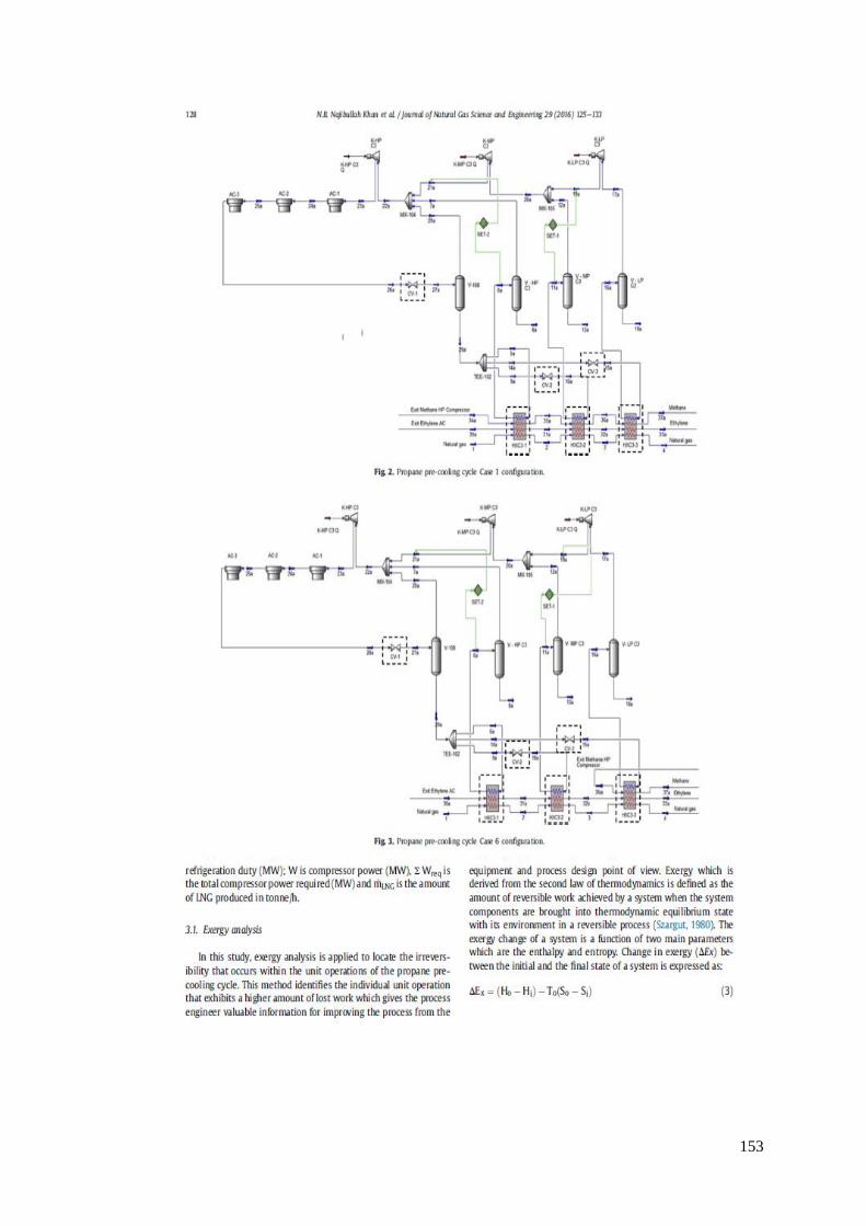
153

154

155
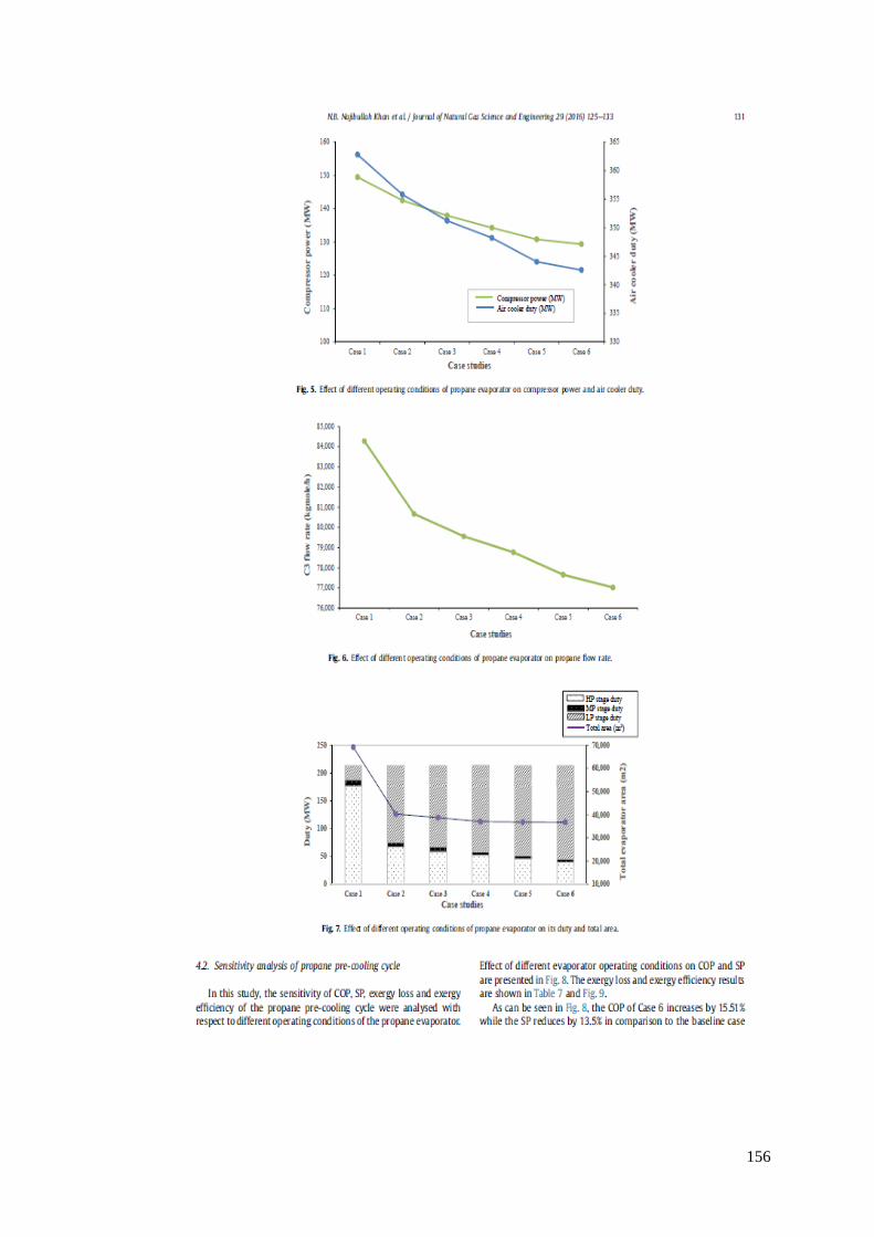
156

157

158

159

160
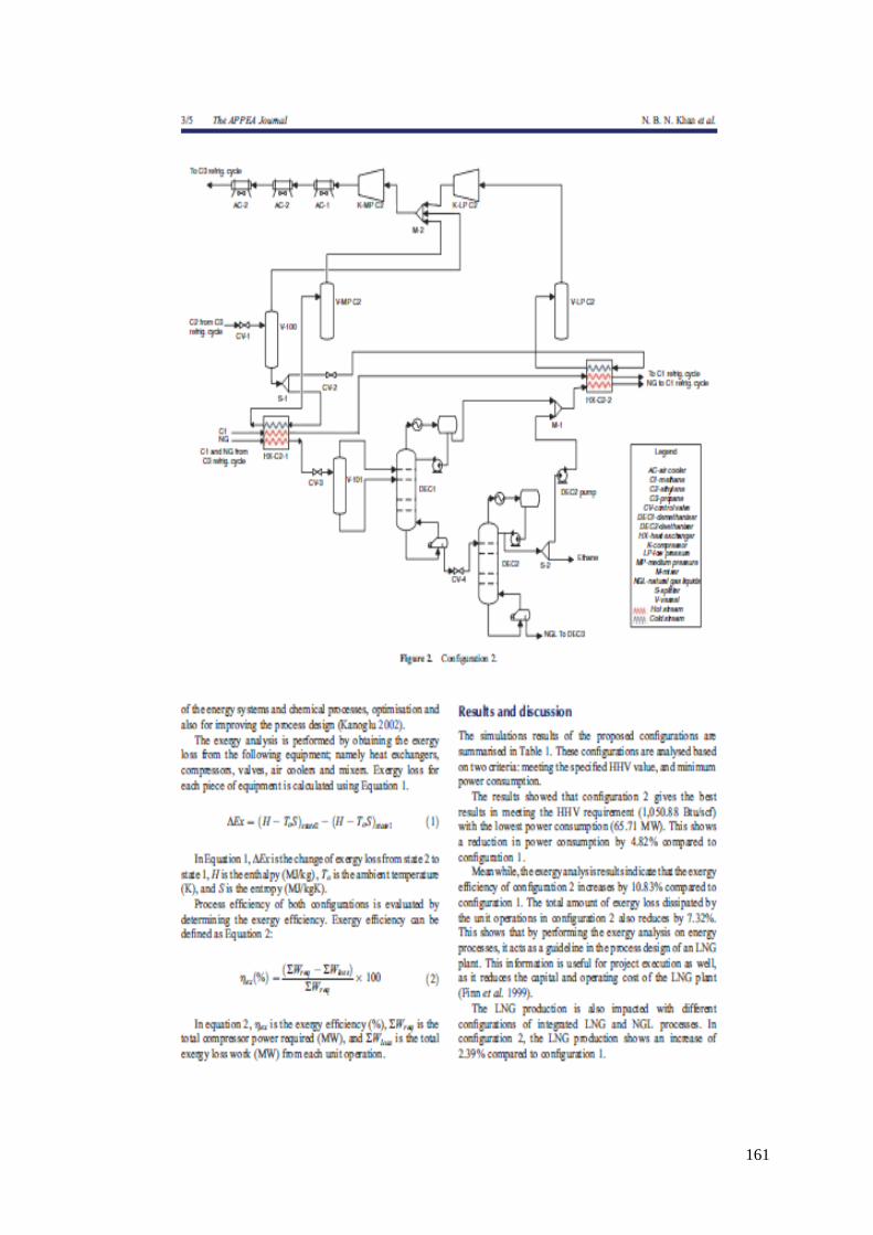
161
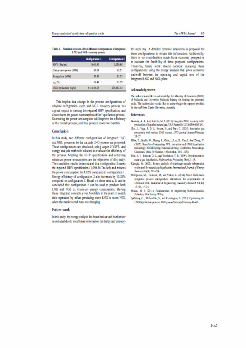
162

163

164
Appendix C – Author attribution statements by the co-authors
To Whom It May Concern
I, Nazreen Begum Najibullah Khan, contributed to the background, modelling and
simulation, thermodynamic analyses and all the results, discussion and conclusion to the
paper publication entitled Najibullah Khan, N.B., A. Barifcani, M. Tade, and V. Pareek, A
case study: Application of energy and exergy analysis for enhancing the process efficiency of
a three stage propane pre-cooling cycle of the cascade LNG process. Journal of Natural Gas
Science and Engineering, 2016. 29: p. 125-133.
DOI (http://dx.doi.org/10.1016/j.jngse.2015.12.034)
___________________
I, as a Co-Author, endorse that this level of contribution by the candidate indicated above is
appropriate.
Nazreen Begum Najibullah Khan ____________________
(Signature of Co-Author 1)
Ahmed Barifcani ____________________
(Signature of Co-Author 2)
Moses Tade ____________________
(Signature of Co-Author 3)
Vishnu Pareek ____________________
(Signature of Co-Author 4)

165
To Whom It May Concern
I, Nazreen Begum Najibullah Khan, contributed to the background, modelling and
simulation, thermodynamic analyses and all the results, discussion and conclusion to the
paper publication entitled Najibullah Khan, N.B., A. Barifcani, M. Tade, and V. Pareek,
Exergy analysis of an ethylene refrigeration cycle integrated with a NGL recovery
process for a large LNG train. The APPEA Journal, 2016. 56(2): p. 606-606.
DOI (https://doi.org/10.1071/AJ15112)
___________________
I, as a Co-Author, endorse that this level of contribution by the candidate indicated above is
appropriate.
Nazreen Begum Najibullah Khan ____________________
(Signature of Co-Author 1)
Ahmed Barifcani ____________________
(Signature of Co-Author 2)
Moses Tade ____________________
(Signature of Co-Author 3)
Vishnu Pareek ____________________
(Signature of Co-Author 4)

166
To Whom It May Concern
I, Nazreen Begum Najibullah Khan, contributed to the background, modelling and
simulation, thermodynamic analyses and all the results, discussion and conclusion to the
paper publication entitled Najibullah Khan, N.B., A. Barifcani, M. Tade, and V. Pareek,
Effect of deethaniser (De-C2) column pressure on the process efficiency of an integrated
LNG/NGL Plant, to be submitted to another journal.
___________________
I, as a Co-Author, endorse that this level of contribution by the candidate indicated above is
appropriate.
Nazreen Begum Najibullah Khan ____________________
(Signature of Co-Author 1)
Ahmed Barifcani ____________________
(Signature of Co-Author 2)
Moses Tade ____________________
(Signature of Co-Author 3)
Vishnu Pareek ____________________
(Signature of Co-Author 4)

167
To Whom It May Concern
I, Nazreen Begum Najibullah Khan, contributed to the detailed literature review of LNG
processes, the process flow schemes and all other work to the paper publication entitled
Najibullah Khan, N.B., A. Barifcani, M. Tade, and V. Pareek, A review of LNG processes
that are suitable for a single large-scale LNG train, to be submitted to another journal.
___________________
I, as a Co-Author, endorse that this level of contribution by the candidate indicated above is
appropriate.
Nazreen Begum Najibullah Khan ____________________
(Signature of Co-Author 1)
Ahmed Barifcani ____________________
(Signature of Co-Author 2)
Moses Tade ____________________
(Signature of Co-Author 3)
Vishnu Pareek ____________________
(Signature of Co-Author 4)

168
References
1. ExxonMobil, The Outlook for Energy : A view to 2040. 2011. p. 43.
2. BP. Statistical Review of World Energy. 2018; 67th:[Available from:
https://www.bp.com/en/global/corporate/energy-economics/statistical-review-of-
world-energy.html.
3. Kumar, S., et al., LNG: An eco-friendly cryogenic fuel for sustainable development.
Applied Energy, 2011. 88(12): p. 4264-4273.
4. Okamura, T., M. Furukawa, and H. Ishitani, Future forecast for life-cycle
greenhouse gas emissions of LNG and city gas 13A. Applied Energy, 2007. 84(11):
p. 1136-1149.
5. Correljé, A.F., Markets for natural gas. Encyclopedia of Energy, 2004. 3: p. 799-
808.
6. Dong, K., R. Sun, J. Wu, and G. Hochman, The growth and development of natural
gas supply chains: The case of China and the US. Energy Policy, 2018. 123: p. 64-
71.
7. Oshima, K., et al., The utilization of LH2 and LNG cold for generation of electric
power by a cryogenic type stirling engine. Cryogenics, 1978. 18(11): p. 617-620.
8. Angelino, G., The use of liquid natural gas as heat sink for power cycles. Journal of
Engineering for Power, 1978. 100(1): p. 169-177.
9. Karashima, N. and T. Akutsu. Development of LNG cryogenic power generation
plant. in Proc., Intersoc. Energy Convers. Eng. Conf.;(United States). 1982. Tokyo
Electric Power Company, Inc., Japan.
10. Kim, C., S. Chang, and S. Ro, Analysis of the power cycle utilizing the cold energy
of LNG. International Journal of Energy Research, 1995. 19(9): p. 741-749.
11. Aspelund, A. and T. Gundersen, A liquefied energy chain for transport and
utilization of natural gas for power production with CO 2 capture and storage–Part
1. Applied Energy, 2009. 86(6): p. 781-792.
12. Zhang, N. and N. Lior, A novel near-zero CO 2 emission thermal cycle with LNG
cryogenic exergy utilization. Energy, 2006. 31(10): p. 1666-1679.
13. De Carvalho Jr, A.V., Natural gas and other alternative fuels for transportation
purposes. Energy, 1985. 10(2): p. 187-215.
14. HS., W., Liquid natural gas a transport fuel in heavy trucking industry, technical
report, sponsored by US department of energy. 1994-1995.
15. Litzke, W.-L. and J. Wegrzyn, Natural gas as a future fuel for heavy-duty vehicles.
2001, SAE Technical Paper.
16. S., H., LNG as alternative transport fuel. Natural gas solution for heavy vehicles
seminar. 2009: Melbourne.

169
17. Letter, I.C.N., The fertilizer industry as the largest domestic consumer of LNG, in
Indonesian Commercial News Letter. 1991: Indonesia.
18. Jaramillo, P., W. Griffin, and H. Matthews, Comparative Life-Cycle Air Emissions
of Coal, Domestic Natural Gas, LNG, and SNG for Electricity Generation.
Environmental Science & Technology, 2007. 41(17): p. 6290-6296.
19. U.S. Annual Energy Outlook 2016 with projections to 2040. 2016.
20. Kirillov, N., Liquefied Natural Gas as a Motor Fuel and a Refrigerant: Methodology
of Evaluation of Ecological Suitability of Truck-Mounted Refrigerating Systems.
Chemical and Petroleum Engineering, 2002. 38(5): p. 344-350.
21. AS, L.H.K.S. The LNG future seen from a ship owner. in Magalog conference. 2007.
22. Hekkert, M.P., F.H.J.F. Hendriks, A.P.C. Faaij, and M.L. Neelis, Natural gas as an
alternative to crude oil in automotive fuel chains well-to-wheel analysis and
transition strategy development. Energy Policy, 2005. 33(5): p. 579-594.
23. Hondo, H., Life cycle GHG emission analysis of power generation systems:
Japanese case. Energy, 2005. 30(11): p. 2042-2056.
24. Kannan, R., K.C. Leong, R. Osman, and H.K. Ho, Life cycle energy, emissions and
cost inventory of power generation technologies in Singapore. Renewable and
Sustainable Energy Reviews, 2007. 11(4): p. 702-715.
25. Chem, O., Schaum's outline series.
26. Lim, W., K. Choi, and I. Moon, Current Status and Perspectives of Liquefied
Natural Gas (LNG) Plant Design. Industrial & Engineering Chemistry Research,
2013. 52(9): p. 3065-3088.
27. Wood, D.A., A review and outlook for the global LNG trade. Journal of Natural Gas
Science and Engineering, 2012. 9: p. 16-27.
28. NETL, D., Liquefied Natural Gas: Understanding the Basic Facts. 2005.
29. Klinkenbijl, J.M., M.L.Dillon, and E.C. Heyman, Gas Pre-Treatment and their
impact on Liquefaction Processes, in 78th Annual GPA Convention 1999: Nashville,
TN, USA.
30. Mokhatab, S., J.Y. Mark, J.V. Valappil, and D.A. Wood, Handbook of liquefied
natural gas, ed. J.Y. Mak, J.V. Valappil, and D.A. Wood. 2013, Burlington: Elsevier
Science.
31. Mortazavi, A., et al., Performance enhancement of propane pre-cooled mixed
refrigerant LNG plant. Applied Energy, 2012. 93: p. 125-131.
32. Hudson, H.M., J.D. Wilkinson, K.T. Cuellar, and M.C. Pierce, Integrated liquids
recovery technology improves LNG production efficiency, in 82nd Convention of the
Gas Processors Association. 2003: Midland, Texas, USA. p. 1-9.
170
33. Elliot, D., et al., Benefits of integrating NGL extraction and LNG liquefaction
technology. AIChE Journal, 2005: p. 1943-1958.
34. Cuellar, K.T., J.D. Wilkinson, H.M. Hudson, and M.C. Pierce, CO-Producing LNG
from cyrogenic NGL recovery plants in 81st Convention of the Gas Processors
Association. 2002: Dallas, Texas, USA. p. 1-8.
35. Kanoğlu, M., Cryogenic turbine efficiencies. Exergy, An International Journal, 2001.
1(3): p. 202-208.
36. (EIA), U.S.E.I.A., The Global Liquefied Natural Gas Market: Status & Outlook.
2003.
37. Hasan, M.M.F., I.A. Karimi, and H.E. Alfadala. Optimizing Compressor Operation
in an LNG Plant. in Proceedings of the 1st Annual Gas Processing Symposium.
2009. Amsterdam: Elsevier.
38. Hatcher, P., R. Khalilpour, and A. Abbas, Optimisation of LNG mixed-refrigerant
processes considering operation and design objectives. Computers & Chemical
Engineering, 2012. 41: p. 123-133.
39. Union, I.G., IGU World Gas LNG report in 27th World Gas Conference 2018,
International Gas Union: Washington DC. p. 1-106.
40. Spilsbury, C., S. McLauchlin, and B. Kennington, Optimising the LNG liquefaction
Process. LNG journal, 2005(January/February): p. 40-43.
41. McKeever, J., M. Pillarella, and R. Bower, An ever evolving technology. LNG
Industry Spring, 2008.
42. Pillarella, M., J.C. Bronfenbrenner, Y. Liu, and M. Roberts. Large LNG trains:
Developing the optimal process cycle. in Gastech 2005 Conference & Exhibition,
Bilbao, Spain. 2005.
43. Wood, D., Profitable year so far, but cost and demand challenges confront
suppliers. World Oil, 2007. 228(10): p. 129-132.
44. Li, Y., X. Wang, and Y. Ding, An optimal design methodology for large-scale gas
liquefaction. Applied Energy, 2012. 99: p. 484-490.
45. Eaton, A., et al. Lowering LNG unit costs through large and efficient LNG
liquefaction trains–What is the optimal train size. in AIChE Spring Meeting, New
Orleans, Louisiana. 2004.
46. Paradowski, H., M. Bamba, and C.Bladanet, Propane Precooling Cycles for
Increased LNG Train Capacity, in 14th International Conference and Exhibitions on
Liquefied Natural Gas 2004: Doha, Qatar 21-24 March. p. 1-18.
47. Vatani, A., M. Mehrpooya, and B. Tirandazi, A novel process configuration for co-
production of NGL and LNG with low energy requirement. Chemical Engineering
and Processing: Process Intensification, 2013. 63: p. 16-24.

171
48. Melaaen, I. and G. Owren, How do the inaccuracies of enthalpy and vapour-liquid
equilibrium calculations influence baseload LNG plant design? Computers &
chemical engineering, 1996. 20(1): p. 1-11.
49. Wang, M., J. Zhang, and Q. Xu, Optimal design and operation of a C3MR
refrigeration system for natural gas liquefaction. Computers & Chemical
Engineering, 2012. 39: p. 84-95.
50. Mehrpooya, M., A. Jarrahian, and M.R. Pishvaie, Simulation and exergy-method
analysis of an industrial refrigeration cycle used in NGL recovery units.
International Journal of Energy Research, 2006. 30(15): p. 1336-1351.
51. Kanoglu, M., Exergy analysis of multistage cascade refrigeration cycle used for
natural gas liquefaction. International Journal of Energy Research, 2002. 26(8): p.
763-774.
52. Najibullah Khan, N.B., A. Barifcani, M. Tade, and V. Pareek, Exergy analysis of an
ethylene refrigeration cycle integrated with a NGL recovery process for a large
LNG train. The APPEA Journal, 2016. 56(2): p. 606-606.
53. Najibullah Khan, N.B., A. Barifcani, M. Tade, and V. Pareek, A case study:
Application of energy and exergy analysis for enhancing the process efficiency of a
three stage propane pre-cooling cycle of the cascade LNG process. Journal of
Natural Gas Science and Engineering, 2016. 29: p. 125-133.
54. Remeljej, C. and A. Hoadley, An exergy analysis of small-scale liquefied natural gas
(LNG) liquefaction processes. Energy, 2006. 31(12): p. 2005-2019.
55. Vatani, A., M. Mehrpooya, and A. Palizdar, Energy and exergy analyses of five
conventional liquefied natural gas processes. International Journal of Energy
Research, 2014: p. 1843-1863.
56. Cipolato, L., et al., Exergetic optimization of a refrigeration cycle for natural gas
liquefaction. 2012. 31: p. 440-444.
57. Lee, G., R. Smith, and X. Zhu, Optimal synthesis of mixed-refrigerant systems for
low-temperature processes. Industrial & engineering chemistry research, 2002.
41(20): p. 5016-5028.
58. Nogal, F.D., J.-K. Kim, S. Perry, and R. Smith, Optimal design of mixed refrigerant
cycles. Industrial & Engineering Chemistry Research, 2008. 47(22): p. 8724-8740.
59. Cammarata, G., A. Fichera, and D. Guglielmino, Optimization of a liquefaction
plant using genetic algorithms. Applied Energy, 2001. 68(1): p. 19-29.
60. Aspelund, A., et al., An optimization-simulation model for a simple LNG process.
Computers & Chemical Engineering, 2010. 34(10): p. 1606-1617.
61. Shukri, T., LNG technology selection. Hydrocarbon engineering, 2004. 9(2): p. 71-
74.

172
62. Pettersen, J., LNG plant equipment (Statoil), in Seminar with Supplier Association
Murmanshelf. 2012: Murmansk, Russia.
63. Pillarella, M., Y.-N. Liu, J. Petrowski, and R. Bower. The C3MR liquefaction cycle:
versatility for a fast growing, ever changing LNG Industry. in 15th International
Conference on LNG. 2007. Barcelona, Spain.
64. Liu, Y., C. Lucas, R. Bower, and J. Bronfenbrenner, Reducing LNG costs by better
capital utilization, in 13th International Conference and Exhibition on Liquefied
Natural Gas (LNG 13). 2001: Seoul, Korea. p. 14-17.
65. Chang, H.-M., M.J. Chung, S. Lee, and K.H. Choe, An efficient multi-stage
Brayton–JT cycle for liquefaction of natural gas. Cryogenics, 2011. 51(6): p. 278-
286.
66. Brimm, A.E., S. Ghosh, and D. Hawrysz, Operating Experience With the Split MR
Machinery Configuration of the C3MR LNG Process. SPE Projects, Facilities &
Construction, 2006. 1(02): p. 1-5.
67. Chiu, C.-H., T. Tsang, M. Chapeaux, and C. Chen, Improve Energy Efficiency in
LNG Production for Baseload LNG Plants, in 25th World Gas Conference. 2012:
Kuala Lumpur, Malaysia.
68. Nored, M. A historical review of turbomachinery for LNG applications. in LNG17.
2013. Houston, Texas, USA
69. Roberts, M.J., Y.-N. Liu, J.C. Bronfenbrenner, and J.M. Petrowski. Reducing LNG
capital costs in today's competitive environment in 14th International Conference
and Exhibition on Liquefied Natural Gas (LNG 14). 2004. Doha, Qatar.
70. Thompson, G., et al. Qatargas II: Full Supply Chain Overview. in LNG 14th
Conference. Qatar. 2004.
71. Bukowski, J., Y.N. Liu, S. Boccella, and L. Kowalski. Innovations-in-natural-gas-
liquefaction-technology for future LNG plants and floating LNG facilities. in
International Gas Union Research Conference. 2011.
72. Castaneda, G., FLNG process and safety considerations. LNG Journal, 2015.
73. van de Graaf, J.M. and B. Pek, Large-capacity LNG trains–The shell parallel mixed
refrigerant process. LNG Review 2005, 2005.
74. Fisher, B. and P. Boutelant. A new LNG process is now available. in GPA Europe
Technical Meeting, London, England. 2002.
75. Martin, P., J. Pigourier, and P. Boutelant. Liquefin: An innovative process to reduce
LNG costs. in 22nd World Gas Conference, Tokyo, Japan. 2003.
76. LNG Solutions from the leader in Cryogenics 'Air Liquide'. LNG Industry, 2017: p.
1-68.

173
77. Burin de Roziers, T. and B. Fischer. New Trends in LNG Process Design. in GPA
Europe Meeting, London, England (Feb. 19, 1999). 1999.
78. Knott, T., Cool future for gas. Frontiers, 2001: p. 10-16.
79. Heiersted, R., R. Jensen, R. Pettersen, and S. Lillesund. Capacity and technology for
the Snøhvit LNG plant. in LNG 13 Conference. 2001.
80. Bach, W., Developments in the mixed fluid cascade process (MFCP) for LNG
baseload plants. Reports on science and technology, 2002. 63: p. 25-28.
81. Statoil. Snohvit LNG Project. 2005.
82. Martin, P.-Y., J. Pigourier, and B. Fischer. Natural gas liquefaction processes
comparison. in 14th International Conference & Exhibition on liquefied Natural gas
(LNG 14). 2004. Doha, Qatar.
83. Houser, C.G. and L.C. Krusen. Phillips Optimized Cascade LNG Process. in
Gastech 96 Conference and Exhibition. 1996. Vienna, Austria.
84. Andress, D. and R. Watkins. Beauty of simplicity: Phillips optimized cascade LNG
liquefaction process. in AIP Conference Proceedings. 2004. AIP.
85. Company, C., ConocoPhillips Liquefied Natural Gas Brochure, C. Company,
Editor. 2016.
86. Jamieson, D., P. Johnson, and P. Redding. Targeting and achieving lower cost
liquefaction plants. in 12th International Conference and Exhibition on Liquefied
Natural Gas (LNG 12). 1998. Perth, Australia.
87. Company, C., ConocoPhillips Optimized Cascade Process Brochure, C. Company,
Editor. 2009.
88. Finn, A.J., G.L. Johnson, and T.R. Tomlinson, Developments in natural gas
liquefaction. Hydrocarbon Processing, 1999. 78(4): p. 1-18.
89. Diocee, T.S., P. Hunter, A. Eaton, and A. Avidan. Atlantic LNG Train 4 "The
World's Largest LNG train". in 14th International Conference and Exhibition on
Liquefied Natural Gas (LNG 14) 2004. Doha, Qatar.
90. Avidan, A., F. Richardson, K. Anderson, and B. Woodard. LNG Plant Scale-up
Could Cut Costs Further. in Fundamentals of the Global LNG Industry. 2001.
London, UK: Petroleum Economist.
91. Company, P.P., LNG showpiece after 20 years of operation. Performance, 1990.
103(May/June): p. 19-20.
92. Fatt, C.C. and A. Omarali, Brunei LNG's MCHE replacement project. LNG journal,
2005: p. 57-58.
93. Cengel, Y.A. and M.A. Boles, Thermodynamics : an engineering approach. 6th ed,
ed. M.A. Boles. 2002, Boston, Mass.: Boston, Mass. : McGraw-Hill Higher
Education.

174
94. Moran, M.J., Engineering thermodynamics, in The CRC Handbook of Mechanical
Engineering, Second Edition. 2004, CRC Press.
95. Szargut, J., International Progress in Second Law Analysis Energy 1980. 5: p. 709-
718.
96. Kidnay, A.J. and W. Parrish, Fundamentals of natural gas processing. 2nd ed, ed.
W.R. Parrish and D.G. McCartney. 2006, Boca Raton: CRC Press.
97. Chang, H.-M., A thermodynamic review of cryogenic refrigeration cycles for
liquefaction of natural gas. Cryogenics, 2015. 72: p. 127-147.
98. Moran, M.J. and H.N. Shapiro, Fundamentals of engineering thermodynamics 5th
ed, ed. H.N. Shapiro. 2006, Chichester, West Sussex, England; Hoboken, NJ: John
Wiley & Sons.
99. Kidnay, A.J. and W. Parrish, Chapter 13: Liquefied Natural Gas, in Fundamentals
of natural gas processing, W. Parrish, Editor. 2006, Boca Raton : CRC Press: Boca
Raton.
100. Khan, M.S., S. Lee, M. Getu, and M. Lee, Knowledge inspired investigation of
selected parameters on energy consumption in nitrogen single and dual expander
processes of natural gas liquefaction. Journal of Natural Gas Science and
Engineering, 2015. 23: p. 324-337.
101. Foglietta, J.H., Consider dual independent expander refrigeration for LNG
production. Hydrocarbon Processing, 2004. 83(1): p. 39-44.
102. Smith, R., Chemical Process Design and Integration 2005, Chichester, West Sussex,
England: John Wiley & Sons Ltd.
103. Khan, M.S. and M. Lee, Design optimization of single mixed refrigerant natural gas
liquefaction process using the particle swarm paradigm with nonlinear constraints.
Energy, 2013. 49: p. 146-155.
104. Yoon, J.-I., et al., Efficiency of Cascade Refrigeration Cycle Using C3H8, N2O, and
N2. Heat Transfer Engineering, 2013. 34(11-12): p. 959-965.
105. Balaras, C.A. and S.M. Jeter, A methodology for selecting and screening novel
refrigerants for use as alternative working fluids. Energy Conversion and
Management, 1991. 31(4): p. 389-398.
106. Yoon, J.-I., et al., Assessment of the performance of a natural gas liquefaction cycle
using natural refrigerants. Heat and Mass Transfer, 2014. 51(1): p. 95-105.
107. Sarkar, J., S. Bhattacharyya, and A. Lal, Selection of suitable natural refrigerants
pairs for cascade refrigeration system. Journal of Power and Energy, 2013. 227(5):
p. 612-622.

175
108. American Society of Heating, R. and E. Air-Conditioning, ASHRAE, handbook of
Fundamentals American Society of Heating, Refrigerating and Air-Conditioning
Engineers handbook. Fundamentals. 1993, Atlanta, Ga.: Atlanta, Ga. : American
Society of Heating, Refrigerating, and Air-Conditioning Engineers, Inc.
109. Poling, B.E., J.M. Prausnitz, and J.P. Connell, The properties of gases and liquids /
Bruce E. Poling, John M. Prausnitz, John P. O'Connell. 5th ed. 2001, New
York: New York : McGraw-Hill.
110. Fox, M.A., Refrigerants and Halocarbons, in Glossary for the Worldwide
Transportation of Dangerous Goods and Hazardous Materials. 1999, Springer. p.
215-217.
111. Liu, Y.N., T. Daugherty, and J. Brofenbrenner. LNG liquefier cycle efficiency. in
Twelfth International Conference and Exhibition on Liquefied Natural Gas, Perth,
Australia. 1998.
112. Rant, Z., Exergy, a new word for technical available work. Forsch. Ing. Wis, 1956.
22(1): p. 36-37.
113. Sato, N., Chemical energy and exergy: an introduction to chemical thermodynamics
for engineers. 2004: Elsevier.
114. Aspelund, A., D.O. Berstad, and T. Gundersen, An Extended Pinch Analysis and
Design procedure utilizing pressure based exergy for subambient cooling. Applied
Thermal Engineering, 2007. 27(16): p. 2633-2649.
115. Cihan, A., O. Hacıhafızogˇlu, and K. Kahveci, Energy–exergy analysis and
modernization suggestions for a combined‐cycle power plant. International Journal
of Energy Research, 2006. 30(2): p. 115-126.
116. Wang, H., X. Shi, and D. Che, Thermodynamic optimization of the operating
parameters for a combined power cycle utilizing low-temperature waste heat and
LNG cold energy. Applied Thermal Engineering, 2013. 59(1-2): p. 490-497.
117. Aljundi, I.H., Energy and exergy analysis of a steam power plant in Jordan. Applied
Thermal Engineering, 2009. 29(2–3): p. 324-328.
118. Kaushik, S.C., V.S. Reddy, and S.K. Tyagi, Energy and exergy analyses of thermal
power plants: A review. Renewable and Sustainable Energy Reviews, 2011. 15(4): p.
1857-1872.
119. Yin, Q., et al. Economic analysis of mixed-refrigerant cycle and nitrogen expander
cycle in small scale natural gas liquefier. in AIP conference proceedings. 2008. AIP.
120. Helgestad, D.-E., Modelling and optimization of the C3MR process for liquefaction
of natural gas. Process Systems Engineering, 2009: p. 44.

176
121. Castillo, L., M. Majzoub Dahouk, S. Di Scipio, and C.A. Dorao, Conceptual
analysis of the precooling stage for LNG processes. Energy Conversion and
Management, 2013. 66: p. 41-47.
122. Castillo, L. and C.A. Dorao, On the conceptual design of pre-cooling stage of LNG
plants using propane or an ethane/propane mixture. Energy Conversion and
Management, 2013. 65: p. 140-146.
123. Ransbarger, W., A fresh look at LNG process efficiency. LNG industry,
2007(SPRING).
124. Majzoub, M., Evaluation and Selection of the Pre-cooling Stage for LNG Processes.
2012, Norwegian University of Science and Technology.
125. Fathalla, B.M., Enhancing Propane Refrigerant Performance at Pre-cooling stage
during hot climate conditions at LNG plants - Case study from Egypt. 2013,
Universiti Teknologi Petronas.
126. Mortazavi, A., et al., Enhancement of APCI cycle efficiency with absorption chillers.
Energy, 2010. 35(9): p. 3877-3882.
127. Kalinowski, P., et al., Application of waste heat powered absorption refrigeration
system to the LNG recovery process. International Journal of Refrigeration, 2009.
32(4): p. 687-694.
128. Mehrpooya, M., M. Hossieni, and A. Vatani, Novel LNG-Based Integrated Process
Configuration Alternatives for Coproduction of LNG and NGL. Industrial &
Engineering Chemistry Research, 2014. 53(45): p. 17705-17721.
129. Cho, J., F.d.l. Vega, H. Kotzot, and C. Durr, Innovative Gas Processing with various
LNG sources. LNG Journal, 2005(January/February): p. 23-27.
130. Brostow, A.A. and M.J. Roberts, Integrated NGL recovery in the production of
liquefied natural gas. 2013, Air Products and Chemicals, Inc., Allentown, PA (US)
US 20130061632A1: USA. p. 1-22.
131. Khan, M.S., Y.D. Chaniago, M. Getu, and M. Lee, Energy saving opportunities in
integrated NGL/LNG schemes exploiting: Thermal-coupling common-utilities and
process knowledge. Chemical Engineering and Processing: Process Intensification,
2014. 82: p. 54-64.
132. He, T. and Y. Ju, Design and Optimization of a Novel Mixed Refrigerant Cycle
Integrated with NGL Recovery Process for Small-Scale LNG Plant. Industrial &
Engineering Chemistry Research, 2014. 53(13): p. 5545-5553.
133. Ransbarger, W.L., Intermediate pressure LNG refluxed NGL recovery process (US
20080098770 Al). 2008, ConocoPhilips Company: USA.
134. Filstead, C., Camel LNG Plant: World's Largest. Hydrocarbon Processing, 1965. 44:
p. 135-138.

177
135. Fahmy, M.F.M., H.I. Nabih, and M. El-Nigeily, Enhancement of the efficiency of the
Open Cycle Phillips Optimized Cascade LNG process. Energy Conversion and
Management, 2016. 112: p. 308-318.
136. Shin, J., S. Yoon, and J.-K. Kim, Application of exergy analysis for improving
energy efficiency of natural gas liquids recovery processes. Applied Thermal
Engineering, 2015. 75: p. 967-977.
137. Lee, S., N.V.D. Long, and M. Lee, Design and Optimization of Natural Gas
Liquefaction and Recovery Processes for Offshore Floating Liquefied Natural Gas
Plants. Industrial & Engineering Chemistry Research, 2012. 51(30): p. 10021-
10030.
138. Mehrpooya, M., A. Vatani, and S.M. Ali Mousavian, Introducing a novel integrated
NGL recovery process configuration (with a self-refrigeration system (open–closed
cycle)) with minimum energy requirement. Chemical Engineering and Processing:
Process Intensification, 2010. 49(4): p. 376-388.
139. Lim, W., et al., Efficient Configuration of a Natural Gas Liquefaction Process for
Energy Recovery. Industrial & Engineering Chemistry Research, 2014. 53(5): p.
1973-1985.
140. Mehrpooya, M., F. Gharagheizi, and A. Vatani, Thermoeconomic analysis of a large
industrial propane refrigeration cycle used in NGL recovery plant. International
Journal of Energy Research, 2009. 33(11): p. 960-977.
141. Al-Azzawi, N.M., Optimal design variables for low temperature distillation columns
in the ethylene plant at petrochemical complex -1 (PC1)-Basrah for revamping, in
Chemical Engineering. 2007, University of Technology, Baghdad: Iraq. p. 244.
142. Engineering Data Book (SI Version). 2004, Gas Processors Suppliers Association:
Tulsa, Oklahoma, United States of America.
143. Castillo, L., et al., Technology selection for liquefied natural gas (LNG) on base-
load plants, in Jornadas de Investigación de la Facultad de Ingeniería (JIFI).
Universidad Central de Venezuela. 2010.
144. Al-Otaibi, D.A., I. Dincer, and M. Kalyon, Thermoeconomic optimization of vapor-
compression refrigeration systems. International Communications in Heat and Mass
Transfer, 2004. 31(1): p. 95-107.
145. Khan, M.S., S. Lee, G.P. Rangaiah, and M. Lee, Knowledge based decision making
method for the selection of mixed refrigerant systems for energy efficient LNG
processes. Applied Energy, 2013. 111: p. 1018-1031.
146. Cao, W.-s., X.-s. Lu, W.-s. Lin, and A.-z. Gu, Parameter comparison of two small-
scale natural gas liquefaction processes in skid-mounted packages. Applied Thermal
Engineering, 2006. 26(8-9): p. 898-904.

178
147. Xu, X., J. Liu, C. Jiang, and L. Cao, The correlation between mixed refrigerant
composition and ambient conditions in the PRICO LNG process. Applied Energy,
2013. 102: p. 1127-1136.
148. Campbell, J.M., Gas conditioning and processing : volume 2, the equipment
modules / by John M. Campbell. 8th ed. The equipment modules, ed. R.A. Hubbard.
Vol. 2. 2004, Norman, Oklahoma: John M. Campbell and Company.
149. Brostow, A.A. and M.J. Roberts, Integrated NGL recovery in the production of
liquefied natural gas, I. Air Products and Chemicals, Editor. 2012, Google Patents:
US.
150. Moran, M.J., Fundamentals of engineering thermodynamics 7th ed.. ed. Engineering
thermodynamics, ed. M.J. Moran. 2011, Hoboken, New Jersey: Wiley
Every reasonable effort has been made to acknowledge the owners of copyright material. I
would be pleased to hear from any copyright owner who has been omitted or incorrectly
acknowledged.