7klvprocess flow for conventional exhaust dyeing and nc-based dyeing. table s1. quantitative...
TRANSCRIPT

Environmentally Sound Textile Dyeing Technology with Nanofibrillated Cellulose
Yunsang Kim1, Lauren Tolbert McCoy1, Eliza Lee1, Hansol Lee2, Raha Saremi1, Corbin Feit1,
Ian R. Hardin1, Suraj Sharma1, Sudhagar Mani2, Sergiy Minko1
1 Nanostructured Materials Lab, University of Georgia, Athens, GA 30602, USA2 College of Engineering, University of Georgia, Athens, GA 30602, USA
Supplementary Information
Methods
Production of NFC hydrogel. Kraft pulp sheets (provided by Weyerhaeuser, Dacula, GA) were
knife-milled three times using a mesh sieve with a pore size of 500 μm to the order of tens of
micrometers in width and hundreds of micrometers in length. Milled cellulose powders were
mixed with hot water and carboxymethyl cellulose (CMC) (0.25% in water, average molecular
weight 250 kD, Sigma-Aldrich). The mixture was processed to nano-size fibers during 2-3
passes in a high-pressure homogenizer (APV-1000, SPX Flow Technology). The prepared NFC
hydrogel (Figure S1) remained stable and showed no signs of phase separation or precipitation
for many months (Zeta potential: -45±5 mV).
Figure S1. Homogenization process: (left to right) cellulose pulp sheet, knife mill, high-pressure
homogenizer, and stable NFC hydrogel containing NFC fibers.
Electronic Supplementary Material (ESI) for Green Chemistry.This journal is © The Royal Society of Chemistry 2017

0 20 40 60 80 100
0
2
4
6
8
Visc
osity
[Pa·
s]
Shear Rate [1/s]
5% 4%3% 2%1% 0.5%
Figure S2. (a) TEM (scale bar 200 nm) and (b) AFM images of NC fibers (0.1 wt% in water); (c)
Viscosity of the NFC gels from 0.5% to 5% as a function of shear rate.
Estimation of specific surface area by methylene blue method. Methylene blue (from Ward’s
Science) was dried at 110°C for several hours before use. A methylene blue solution was
prepared with deionized water and its absorbance at 660 nm was analyzed by a UV-Vis
spectrophotometer (Shimadzu 2401). This wavelength corresponds to the absorption peak of the
molecule.1 In a typical example, 0.36 g of cotton fibers or dry NFC fibers were immersed in 45
mL of various concentrations of methylene blue solutions (from 10 μM to 25 mM) for one day,
in which all surfaces in the cellulosic fibers were occupied by methylene blue molecules (see
Figure S3a). The reduction in the adsorption intensity at 660 nm after one day of immersion
corresponds to the amount of adsorbed methylene blue on the surfaces of cotton and NFC fibers.
From the calibration curve of neat methylene blue solutions at various concentrations (Figure
S3b), the methylene blue adsorption per gram of fiber (mg/g) was calculated and then converted
to the specific surface area of cellulosic fibers, Scf, by using the equation below,
(S1)𝑆𝑐𝑓=
𝑁𝑀𝐵 × 𝑎𝑀𝐵 × 𝑁𝐴𝑀𝑀𝐵
where NMB equals to the molecular weight of methylene blue (MMB) multiplied by the number of
moles of methylene blue per gram of fiber needed to form a monolayer; aMB is the molecular
footprint of methylene blue (130 Å2)2; and NA is Avogadro’s number. NMB was taken at the
maximum of methylene blue adsorption in Figure 1d and 1e.
a b
c

400 500 600 700 800
0.0
0.5
1.0
1.5
2.0
Ab
sorb
ance
Wavelength (nm)
1hr 2hr 4hr 7.5hr 23hr
0 5 10 15 20 25 300.0
0.5
1.0
1.5
2.0
Abso
rban
ce @
660
nm
Concentration of MB (M)
0.0 0.1 0.2 0.3 0.40
1
2
3
MB
adso
rptio
n (m
g/g)
Equilibrium conc. (mM)
cotton fibers
0 5 10 15 20 25
0
50
100
150
200
NFC fibers
MB
adso
rptio
n (m
g/g)
Equilibrium conc. (mM)Figure S3. (a) The absorbance spectra of methylene blue solutions after the immersion of cotton
fabric for 1 to 23 hours. The reduction of absorbance intensity stabilizes after 4 hours of
immersion, indicating that all of the surfaces in cotton fibers are occupied by the absorption of
methylene blue molecules. (b) The absorbance of methylene blue solution at 660 nm in various
concentrations. Linear fit gives an R2 value of 99%. (c-d) Adsorption of methylene blue on
cotton and NFC fibers as a function of methylene blue concentration.
Fabrication of the NFC-dye and coloration of cotton fabrics. Reactive Red 120 dye molecules
(Sigma Aldrich, chemical structure shown in Figure S4a) were incorporated into NFC hydrogels
with Na2SO4 and Na2CO3 as a salt and alkali, respectively, by a simple mixing under ambient
conditions to produce the NFC-dye mixture. The weight percent of the NFC gel determines the
liquor ratio, which is the weight ratio of water to dry cellulose fibers. The NFC-dye was applied
to both sides of the cotton fabric (bleached desized cotton, style #400, 102 g/m2, purchased from
a b
c d

Testfabrics, Inc., USA) by manual squeegee printing. In a typical example, a 2” by 5.1” piece of
cotton fabric whose mass was c.a. 0.7 g was coated by 1.4 g of the NFC-dye. The procedure
shown in Figure S4b was used to produce a cotton reference by an exhaust dyeing method. Table
S1 summarizes the amount of dye and dye auxiliaries used in the coloration of the cotton fabrics
(four 2” by 5.1” swatches, total 2.8 g). After dyeing, the colored fabrics were dried at 120°C for
one hour, followed by a wash-off in which the four colored swatches were boiled in 1 liter of
deionized water for 30 minutes (liquor ratio 370:1) and subsequently dried under ambient
conditions. The rinse water after wash-off was collected to determine the concentration of dye
molecules in the effluent.
Figure S4. (a) Chemical structure of Reactive Red 120 used in this study and (b) the sequence of
the exhaust dyeing method.
a b

Figure S5. Process flow for conventional exhaust dyeing and NC-based dyeing.
Table S1. Quantitative comparison of dye and dye auxiliaries to produce four 2” by 5.1” cotton
fabrics (one batch, total 2.8 g) by exhaust dyeing and NFC-based dyeing (based on 10%).
1% dye
owf
20:1 liquor
ratio
Reactive
Red 120
dye
Water Dye
concentration
Weight
of dry
NC
Salt
(Na2SO4, 64
g/L)
Alkali
(Na2CO3, 4
g/L)
Exhaust
dyeing
28 mg 53 g 0.36 mM N/A 3.4 g 0.21 g
NFC-based
dyeing
28 mg 5.3 g 3.6 mM 280 mg 0.34 g 0.021 g
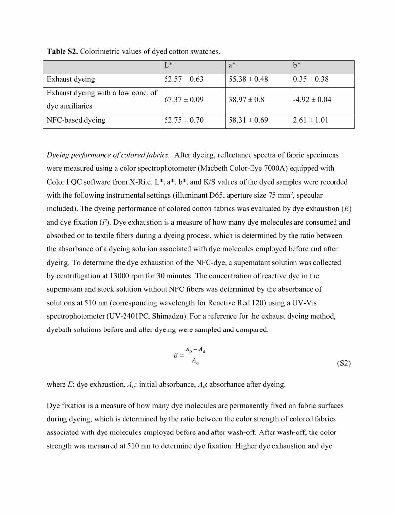
Table S2. Colorimetric values of dyed cotton swatches.
L* a* b*
Exhaust dyeing 52.57 ± 0.63 55.38 ± 0.48 0.35 ± 0.38
Exhaust dyeing with a low conc. of
dye auxiliaries67.37 ± 0.09 38.97 ± 0.8 -4.92 ± 0.04
NFC-based dyeing 52.75 ± 0.70 58.31 ± 0.69 2.61 ± 1.01
Dyeing performance of colored fabrics. After dyeing, reflectance spectra of fabric specimens
were measured using a color spectrophotometer (Macbeth Color-Eye 7000A) equipped with
Color I QC software from X-Rite. L*, a*, b*, and K/S values of the dyed samples were recorded
with the following instrumental settings (illuminant D65, aperture size 75 mm2, specular
included). The dyeing performance of colored cotton fabrics was evaluated by dye exhaustion (E)
and dye fixation (F). Dye exhaustion is a measure of how many dye molecules are consumed and
absorbed on to textile fibers during a dyeing process, which is determined by the ratio between
the absorbance of a dyeing solution associated with dye molecules employed before and after
dyeing. To determine the dye exhaustion of the NFC-dye, a supernatant solution was collected
by centrifugation at 13000 rpm for 30 minutes. The concentration of reactive dye in the
supernatant and stock solution without NFC fibers was determined by the absorbance of
solutions at 510 nm (corresponding wavelength for Reactive Red 120) using a UV-Vis
spectrophotometer (UV-2401PC, Shimadzu). For a reference for the exhaust dyeing method,
dyebath solutions before and after dyeing were sampled and compared.
(S2)𝐸=
𝐴𝑜 ‒ 𝐴𝑑𝐴𝑜
where E: dye exhaustion, Ao: initial absorbance, Ad: absorbance after dyeing.
Dye fixation is a measure of how many dye molecules are permanently fixed on fabric surfaces
during dyeing, which is determined by the ratio between the color strength of colored fabrics
associated with dye molecules employed before and after wash-off. After wash-off, the color
strength was measured at 510 nm to determine dye fixation. Higher dye exhaustion and dye

fixation indicate more efficient and economical dyeing processes as well as producing less dye in
the effluent from dyeing and wash-off.
(S3)𝐹=
𝐶𝑠𝐶𝑜
where F: dye fixation, Co: initial color strength, Cs: color strength after wash-off.
Colorfastness and stiffness of colored fabrics. To determine colorfastness properties, crocking
(dry and wet) and laundering tests were performed based on AATCC Test Method 8-2013 and
61-2013 2A,3 respectively. Stiffness of a colored fabric was evaluated by measuring the bending
length of a fabric under its own mass by using the Cantilever Test, ASTM D1388.
Preparation of a fiber specimen for cross-sectional SEM. The polyethylene film method was
used to prepare cross-sections of fabric specimens. Fibers/fabrics were placed in disposable
polyethylene pipettes and the polyethylene/fiber sandwich was then placed between two glass
microscope slides on a hot plate until the polyethylene melted. After cooling down, the
polyethylene/fiber sandwich was cut in thin slices using a sharp razor blade. The thin slices were
subsequently gold-coated by sputtering.
Cellulose model film. The cellulose model film was spun on a silicon wafer from a cellulose
solution in LiCl / N,N-dimethylacetamide. The silicon wafer was freshly prepared by a base
piranha treatment followed by dipping in a 1% polyethylenimine solution. The spin-cast
cellulose film was rinsed with deionized water to remove the LiCl and dried under ambient
conditions. The root-mean-square roughness of the cellulose films was 0.5 nm. NFC hydrogel
(1%) was deposited on the cellulose model film by spin casting and baked at 120°C overnight.
The thickness of the cellulose and NFC film was determined to be 85 nm and 25 nm respectively
by ellipsometry. The bilayer film was subjected to washing by dipping in a detergent solution
(0.3 g/L) at 50°C for an hour with magnetic stirring.

Figure S6. AFM images of (a) NC gels deposited on regenerated cellulose film and (b) the same
film after washing, indicating good adhesion of nanocellulose fibrils on the cellulose model film.
Life cycle inventory analysis (LCIA). All input and output data used in this study were obtained
from bench scale experimental data, literature sources and the LCI databases - GREET version
1.3.0, Ecoinvent v.2.2 and USLCI v.1.6.0. The collected data were then scaled up for producing
1 kg of dyed cotton fabric on dry basis. The U.S. LCI database was used to extract data for each
of the chemicals and materials used in this study. For some chemicals, the European database
was selected as similar technologies were used to manufacture the selected chemicals. Table S2
summarizes the inventory data for manufacturing 1 kg of dyed cotton fabric using two different
dyeing methods. The experimental data obtained from NFC preparation including knife milling
and homogenization, and the data for dyeing cotton fabrics with the reactive dye (Reactive red
120) and NFC-dye were used in this analysis. The data for wastewater treatment using granular
activated carbon (GAC) were collected from the literature.4, 5
a b

Table S3. Life cycle inventory data for one kg of cotton fabric using two dyeing methods.
Input (Unit) Exhaust
dyeing
NC-based
dyeing
Cotton fabric dyeing process
Bleached Cotton fabric (kg) 1 1
Na2SO4 (g) 1216 121.6
Na2CO3 (g) 76 7.6
Reactive red 120 (g) 10 10
Kraft bleached pulp (g) - 116.64
Carboxymethylcellulose (g) - 0.48
Total deionized (DI) water (L) 389 38.9
DI water for nanocellulose preparation
(L)N/A 1.9
DI water for dyeing (L) 19 N/A
DI water for rinsing (L) 370 37
Total electricity (kwh) 36.76 5.85
Electricity for nanocellulose
preparation (kwh)N/A 1.37
Electricity for dyeing (kwh) 1.59 N/A
Electricity for drying (kwh) 0.8 0.8
Electricity for rinsing (kwh) 34.37 3.44
Electricity for water recycle (kwh) - 0.016
Transport, truck, average fuel (tkm) 0.26 0.048
Wastewater treatment
Hard coal (kg) 0.017 0.0142
Steam (kg) 0.10 0.085
Deionized water (L) 0.20 0.17
Heat, hard coal combustion (MJ) 1.52 1.30
Heat, natural gas combustion (MJ) 1.96 1.68
Electricity (kwh) 0.086 0.032
Transport, truck, combination, average
Fuel (tkm) 0.14 0.12
Output (Unit)

Figure S7. Flow diagram for wastewater treatment by GAC absorption.
Cotton fabric dyeing process
Dyed cotton fabric (kg) 1 1
Particulate >10um (g) N/A 16.64
Heat waste (MJ) 26.47 3.95
Heat waste from nanocellulose
preparation (MJ)N/A 0.89
Heat waste from dyeing (MJ) 26.47 3.06
Water evaporated (kg) 0.7 1.67
Wastewater treatment
Treated effluent (L) 389.59 37.37
Heat waste (MJ) 0.76 0.62
Reactive Red 120 (mg) 241.28 213.01
CO2 (g) 3.25 2.77
NOx (g) 1.08 0.92

Global
warming
Acidific
ation
Eutrop
hicati
on
Ecotox
icity
Smog
Natural
resou
rce de
pletio
n
Wate
r intak
e
Ozone
deple
tion
0%
20%
40%
60%
80%
100%
Exhaust dyeing
Figure S8. Comparative life cycle assessment impacts of dyed cotton fabrics (1 kg) using
exhaust and NC-based dyeing methods.
References
1. C. Kaewprasit, E. Hequet, N. Abidi and J. P. Gourlot, The Journal of Cotton Science,
1998, 2, 164-173.
2. J. C. Santamarina, K. A. Klein, Y. H. Wang and E. Prencke, Canadian Geotechnical
Journal, 2002, 39, 233-241.
3. AATCC Technical Manual, American Association of Textiles Chemists & Colorists, 2015.
4. X. Gabarrell, M. Font, T. Vicent, G. Caminal, M. Sarrà and P. Blánquez, The
International Journal of Life Cycle Assessment, 2012, 17, 613-624.
5. I. Muñoz, J. Peral, J. Antonio Ayllón, S. Malato, M. José Martin, J. Yves Perrot, M.
Vincent and X. Domènech, Environmental Engineering Science, 2007, 24, 638-651.