process pressure transmitter explosion-protected...
TRANSCRIPT

JUMO dTRANS p20 Ex dProcess pressure transmitter
explosion-protected, explosion-proof enclosure
Operating Manual
40302600T90Z001K000
V3.00/EN/00556401

DANGER!
Failure of the pressure transmitter or an device attached to it could possibly lead to dangerous malfunctions!
Suitable preventive measures must be in place to prevent this from happening.
NOTE!
Please read this operating manual before putting the device in operation. Keep the operating manual in a place which is accessible to all users at all times.All the required settings are described in this manual. If any difficulties should nevertheless arise during start-up, please do not manipulate the unit in any way. You could endanger your rights under the device warranty!
Please contact the nearest subsidiary or the head office in such a case.
Inhalt
1 Safety information .................................................................. 51.1 Warning symbols .................................................................................... 51.2 Note symbols .......................................................................................... 5
2 General information ............................................................... 72.1 Scope of application ............................................................................... 72.2 Scope of delivery .................................................................................... 8
3 Identifying the device version ............................................. 113.1 Nameplate ............................................................................................. 113.2 Order details ......................................................................................... 123.3 Accessories .......................................................................................... 143.4 Software ................................................................................................ 143.5 Dimensions ........................................................................................... 153.6 Dimensions of process connections ..................................................... 16
4 Technical data ...................................................................... 174.1 General ................................................................................................. 174.2 Input ...................................................................................................... 184.3 Output ................................................................................................... 184.4 Voltage supply ...................................................................................... 184.5 Mechanical properties .......................................................................... 184.6 Ambient conditions ............................................................................... 194.7 Accuracy ............................................................................................... 204.8 Approvals/marks of conformity ............................................................ 21
5 Mounting ............................................................................... 235.1 Before mounting ................................................................................... 235.2 Unscrewing the front ring or housing cover ......................................... 235.3 Rotating the LCD (display) .................................................................... 245.4 Rotating the enclosure .......................................................................... 255.5 Pressure connection ............................................................................. 265.6 Measuring relative or absolute pressure ............................................... 275.7 Hazardous (Ex) area mounting .............................................................. 30
6 Installation ............................................................................ 316.1 Installation instructions ......................................................................... 31

Inhalt
6.2 Cable gland ........................................................................................... 34
7 Operation .............................................................................. 377.1 Display .................................................................................................. 377.2 Operation with rotary knob or with setup program .............................. 387.3 The level concept .................................................................................. 39
8 Maintenance ......................................................................... 458.1 Eliminating errors and faults ................................................................. 45
9 Declaration of Conformity ................................................... 47
10 EC-type examination certificate ......................................... 49
11 China RoHS .......................................................................... 53

1 Safety information
5
1.1 Warning symbols
1.2 Note symbols
DANGER!
This symbol indicates that personal injury caused by electrical shock may occur if therespective precautionary measures are not carried out.
CAUTION!
This symbol in connection with the signal word indicates that damage to assets or dataloss will occur if the respective precautionary measures are not taken.
NOTE!
This symbol refers to important information about the product, its handling, or additionaluse.

1 Safety information
6
2 General information
2.1 Scope of application
General
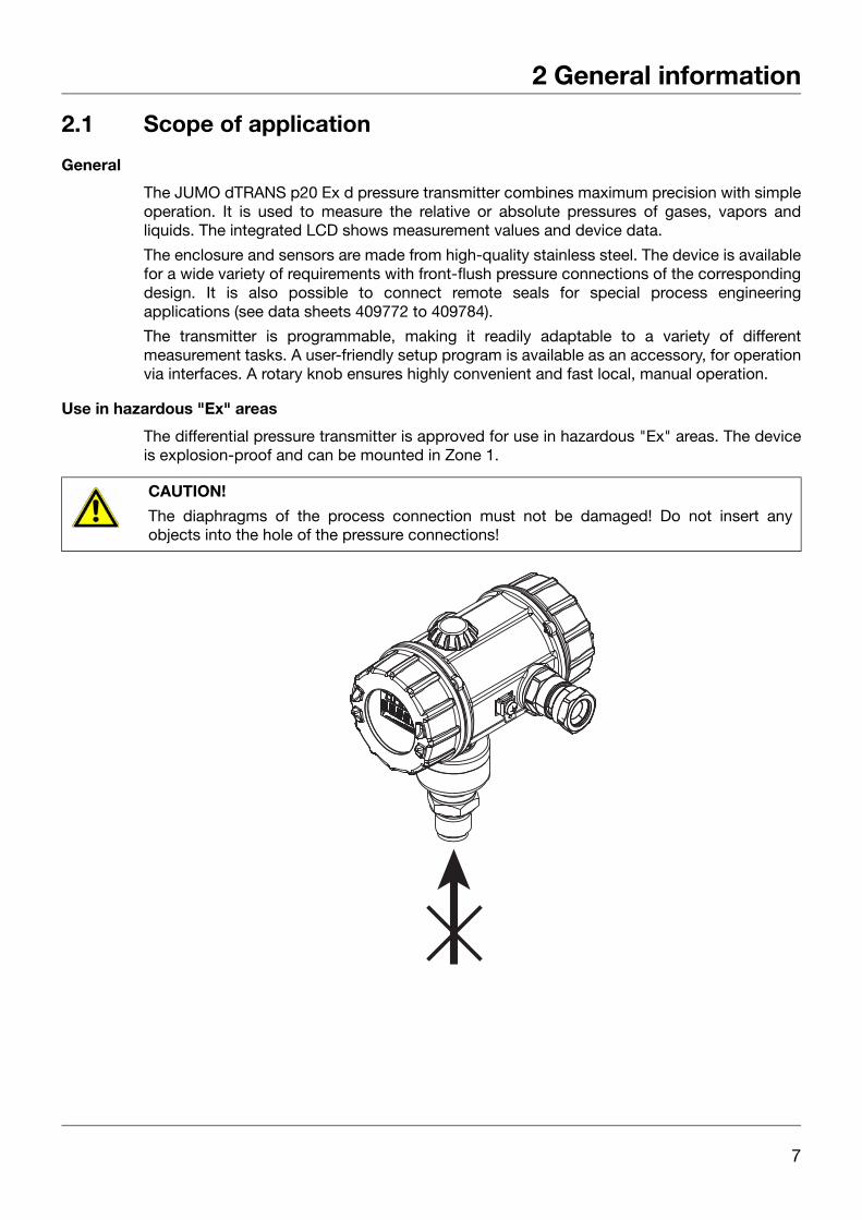
The JUMO dTRANS p20 Ex d pressure transmitter combines maximum precision with simpleoperation. It is used to measure the relative or absolute pressures of gases, vapors andliquids. The integrated LCD shows measurement values and device data.
The enclosure and sensors are made from high-quality stainless steel. The device is availablefor a wide variety of requirements with front-flush pressure connections of the correspondingdesign. It is also possible to connect remote seals for special process engineeringapplications (see data sheets 409772 to 409784).
The transmitter is programmable, making it readily adaptable to a variety of differentmeasurement tasks. A user-friendly setup program is available as an accessory, for operationvia interfaces. A rotary knob ensures highly convenient and fast local, manual operation.
Use in hazardous "Ex" areas
The differential pressure transmitter is approved for use in hazardous "Ex" areas. The deviceis explosion-proof and can be mounted in Zone 1.
CAUTION!
The diaphragms of the process connection must not be damaged! Do not insert anyobjects into the hole of the pressure connections!
7
2 General information
2.2 Scope of delivery
Operating Manual B 403026.0
Operating manual are a guide for mounting, electrical connection, starting up and operating the JUMO dTRANS p20 Ex d pressure transmitter.
Calibration certificate
The pressure transmitter comes with a calibration certificate and a SETUP printout. Thesedocuments contain information about the set parameters or measured parameters for therelevant pressure transmitter.
If the calibration certificate is lost, or if you need another copy, this can be ordered fromJUMO. Please provide the serial number of the pressure transmitter (see nameplate).Your supplier's address can be found on the back of the manual.
Setup program
The setup program is available as an accessory: sales no. 40/00537577.
The setup program provides a convenient way to check and adjust all parameters of thepressure transmitter. It also includes additional functions such as:
• Recording measurement values
• Graphical presentation of temperature and pressure
• Extensive diagnostic messages
• Display of the complete order code and device configuration (for reordering).
The setup program accesses the pressure transmitter via
• the JUMO interface (standard)
• or the HART® interface (optional)
PC interface cable
Available as an accessory: PC interface cable including USB/TTL converter and two adapters(USB connecting cable), part no. 00456352.
The PC interface cable can be used to connect the pressure transmitter to the USB interfaceof a PC via the JUMO interface.
HART® modem
Available as an accessory: HART® modem for USB, part no. 00443447.
The HART® modem can be used to connect the pressure transmitter with the USB®interface of a PC via the HART® interface.
DANGER!
The JUMO interface must not be used in hazardous (Ex) areas!
This device must only be operated with the rotary knob!
8
2 General information
Remote seals
Available as an accessory: see data sheets 409770 to 409786.
Remote seals are used for adaptation to special applications, when conventional pressureconnections cannot be used.
CAUTION!
Remote seals are installed in the factory and must not be separated from the pressuretransmitter!
9

2 General information
10
3 Identifying the device version
3.1 Nameplate
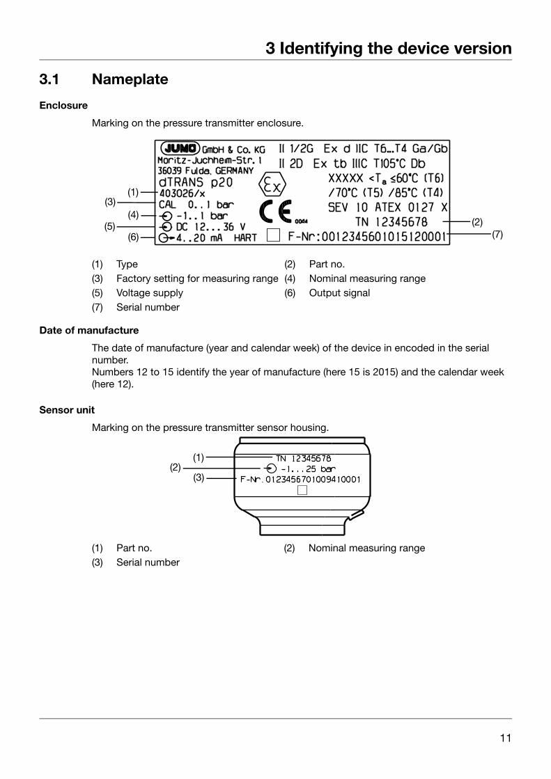
Enclosure
Marking on the pressure transmitter enclosure.
Date of manufacture
The date of manufacture (year and calendar week) of the device in encoded in the serial number.Numbers 12 to 15 identify the year of manufacture (here 15 is 2015) and the calendar week (here 12).
Sensor unit
Marking on the pressure transmitter sensor housing.
(1) Type (2) Part no.(3) Factory setting for measuring range (4) Nominal measuring range(5) Voltage supply (6) Output signal(7) Serial number
(7)(5)
(6)
(3)(1)
(4)(2)
(1) Part no. (2) Nominal measuring range(3) Serial number
(2)(1)
(3)
11

3 Identifying the device version
3.2 Order details(1) Basic type
403026 JUMO dTRANS p20 Ex d – Process pressure transmitter explosion-protected,explosion-proof enclosure
(2) Basic type extension0 None9 Special design
(3) Display0 Without display1 With display
(4) Operation0 Without control knob1 With control knob
(5) Nominal measuring range of input 450 -600 to +600 mbar relative pressure487 0 to 0.6 bar absolute pressure491 0 to 4 bar absolute pressure495 0 to 25 bar absolute pressure507 0 to 100 bar absolute pressurea
513 -1 to +4 bar relative pressure514 -1 to +25 bar relative pressure515 -1 to +100 bar relative pressurea
516 -1 to +600 bar relative pressureb
(6) Output410 4 to 20mA, two wire with HART®
(7) Process connection504 G 1/2 to EN 837512 1/2-14 NPT to DIN 837564 1/2-14 NPT internal571 G 3/4 front-flush to DIN 837583 M20 (× 1.5) with tap604 Tapered adapter with groove union nut DN 25 to DIN 11851 (milk cone)606 Tapered adapter with groove union nut DN 40 to DIN 11851 (milk cone)613 Clamp DN 25/32/40 to DIN 32676616 Clamp DN 50 to DIN 32676/2" ISO 2852997 JUMO PEKA with EHEDG approval998 Suitable for connecting to a diaphragm seal
(8) Process connection material20 CrNi (stainless steel)82 NiMo99 Special process connection material
(9) Measuring system filling medium 00 Without filling medium01 Silicon oil
12

3 Identifying the device version
(10) Extra codes000 None100 Customized settingc
226 With GOST/EAC approvald
227 With INMETRO approval374 Material inspection certificate 3.1 DIN EN 10204 Material452 Parts in contact with the medium are electropolished591 Throttle in pressure channel624 Free of oil and grease630 Enlarged pressure channel634 With TAG number635 With manufacturer declaration NACEe
681 Extended permissible ambient temperature932 With HART® version 5
a This inputs specified above are not available with processs connections 604, 606, 613, 616.b This input is not available with process connections 571, 604, 606, 613, 616, 997.c Please specify required setting in plain text. For factory setting, see Accuracy section.d Upon requeste Only with process connection material 82 (NiMo) and process connection 512 or 564; not available with measuring
range -0.6 to +0.6 bar relative pressure and 0 to 0.6 bar absolute pressure.
(1) (2) (3) (4) (5) (6) (7) (8) (9) (10)Order code / / , ...Order example 403026 / 0 - 1 - 1 - 514 - 410 - 504 - 20 - 1 / 000
13

3 Identifying the device version
3.3 Accessories
3.4 Software
Article Part no.PC interface with USB/TTL convertera 00456352HART® modem USBb 00443447Mounting bracket for 2“ pipe and wall 00597711
Data sheetManifolds 409706JUMO PEKA - Process connection adapter with EHEDG approval 409711Pressure separator with milk pipe fitting DIN 11851 409772Pressure separator with clamp connection 409774Pressure separator with DRD flange or Varivent connection 409776Pressure separator with ISS connection or SMS connection or RJT connection and slotted ring nut
409778
Diaphragm chemical seals 4MDV-10 409780Pressure separator with male thread ISO 228/1 or ANSI B 1.201 409782Pressure separator with flange connection EN 1092-1 with sealing lip Form B1 409784Pressure separator with flange connection to ANSI B 16.5 with sealing lip Form RF 409786Ex-i Power supply/input isolating amplifier 707530
a The PC interface cable is the connection between the JUMO interface of the pressure transmitter and the USBinterface of a PC.
b The HART® modem is the connection between the HART® interface of the pressure transmitter and the USB in-terface of a PC.
Article Part no.JUMO Setup dTRANS p20 series 00537577
14

3 Identifying the device version
3.5 Dimensions
A = Cable gland M20 × 1.5
145
116
72
ø7
3
116
A
15

3 Identifying the device version
3.6 Dimensions of process connections
Dimensions of process connections 604, 606 and 613
504(G 1/2)
512(1/2-14 NPT)
564(1/2-14 NPT internal)
571(G 3/4)
604 and 606(Tapered adapter with groove union nut to DIN 11851)
613 und 616(Clamp to DIN 32676)
997(JUMO PEKA)
G 1/2
203
0.5
1/2-14 NPT
30.5
20
SW 27
23.5
1/2-14 NPT
32
16
SW 32
G 3/4
L1
L2
15
D2
D1 31.5
SW 27
11
Connection DN D1 D2 D3 D4 L1 L2604 25 Ø 44 Ø 35 Rd 52 × 1/6“ Ø 63 15 21606 40 Ø 56 Ø 48 Rd 65 × 1/6“ Ø 78613 25 Ø 43.5 Ø 50.5
16

4 Technical data
4.1 General
Reference conditions DIN 16086, DIN EN 60770 and DIN IEC 770/5.3Sensor system Silicon sensor with stainless steel separation diaphragmPressure transfer mediumFor measuring system 1 filling medium Silicon oilFor measuring system 2 filling medium Halogenated filling oilPermissible load change > 10 millionLocationMounting position AnyCalibration position Device standing vertically, process connection on bottomPosition-dependent zero point offset 1 mbar; Zero point correction possible locally or via setupDisplay LCD, two-line with bar graphAlignment Display unit can be rotated 90° at a time;
Housing can be rotated ±160°Size Display field 22 × 35 mm/font size 7 mm/5 digitsColor BlackMeasurement unit display optionsInput pressure mH2O, inH2O, inHg, ftH2O, mmH2O, mmHg, psi, bar, mbar,
kg/cm2, kPa, Torr, MPaMeasurement value % or scaled with a freely adjustable measurement unitOutput current mASensor temperature °C; °FAdditional display data Minimum pressure, maximum pressure, error, overrange,
underrange, operating hours, device parametersOperationLocal With rotary knob and LCDSetup program Via interfaceInterfaceStandard JUMO interfacea, socket on front of deviceFor output 410 (4 to 20 mA with HART®) JUMO interfacea and HART® interface
a Neither the JUMO interface nor the HART® interface must be used in potentially explosive atmospheres! In this-situation, the device must only be operated with the rotary knob!
NOTE!
For special conditions see chapter 4.4 and 4.6 and 6.4.
17

4 Technical data
4.2 Input
4.3 Output
4.4 Voltage supply
4.5 Mechanical properties
Relative pressureNominal measuring range
-0,6 to +0,6 bar rel.
-1 to +4 barrel.
-1 to +25 barrel.
-1 to +100 barrel.
-1 to +600 barrel.
Overload capacity 6 bar 30 bar 150 bar 300 bar 1200 barBursting pressure 12 bar 60 bar 250 bar 400 bar 2000 bar
Absolute pressureNominal measuring range
0 to 600 mbar abs. 0 bis 4 barabs.
0 bis 25 barabs.
0 bis 100 barabs.
Overload capacity 6 bar 30 bar 150 bar 300 barBursting pressure 12 bar 60 bar 250 bar 400 bar
Analog outputFor output 405 4 to 20 mA, two-wireFor output 410 4 to 20 mA, two-wire with HART® version 7
(version 5 optional, extra code 932)Step response time T60 190 ms without dampingDamping Adjustable 0 to 100 sBurdenFor output 405 (4 to 20 mA) Burden (UB-12 V) ÷ 0.022 AFor output 410 (4 to 20 mA with HART®) Burden (UB-12 V) ÷ 0.022 A;
additional: min. 250 , max. 1100
Voltage supply DC 12 to 36 V
Prozess connectionFor material 20 316L at front-flush process connection
316Ti sonstFor material 82 2.4819 NiMoSurface Ra 0,8 µmProcess sealFor process connection 512 and 571 FPMFor process connection 652 FPMFor process connection 997 (JUMO PEKA)
FDA-compliant: FPM, VMQ, EPDM also available,see data sheet 409711
For all other process connections Without a seal
18

4 Technical data
4.6 Ambient conditions
Measuring membraneFor material 20 1.4542 at measuring range 516
316L sonstFor material 82 2.4819 NiMoSurface Ra 0.8 µmHousingHousing material Precision casting 1.4408Cover material Precision casting 1.4408, FPM sealControl knob materialFor operation 0 (without control knob) -For operation 1 (with control knob) PAExplosion protection EC-type examination certificate SEV 10 ATEX 0127 X
II 1/2G Ex d IIC T6 ... T4 Ga/GbII 2D Ex tb IIIC T105 °C Db
Weight Approx. 1.6 kg
Permissible temperaturesOperation Version Category Max. medium
temperatureAmbient temperaturea
Extende ambient temperature(extra code 681)a, b
II 1/2G Ex d T6 +70 °C -40 to +60 °C -50 to +60 °CT5 +85 °C -40 to +70 °C -50 to +70 °CT4 +115 °C -40 to +85 °C -50 to +85 °C
II 2D Ex tb T105 °C +100 °C -40 to +85 °C -50 to +85 °CStorage -40 to +85 °CPermissible relative humidityOperation 100% incl. condensation on device outer sleeveStorage 90% without condensationPermissible mechanical loadingVibration performance 2 g, 10 to 500 Hz to EN 60770-3Shock resistance 15 g for 6 ms to IEC 60068-2-27Electromagnetic compatibility To EN 61326Interference emission Class BInterference resistance IndustrialProtection IP66 to EN 60529
a Restricted function below -20 °C: stationary use, increased danger of broken cable, display does not function; de-vice cannot be operated when temperature is under -30 °C.
b In the range of -40 to -50 °C the device must be permanently in operation. The cover with the device viewing panemust also be protected against mechanical shock and impact. For details please contact JUMO.
19

4 Technical data
4.7 Accuracy
Relative pressureNominal measuring range
-0.6 to +0.6 bar rel.
-1 to +4 bar rel.
-1 to +25 bar rel.
-1 to +100 bar rel.
-1 to +600 bar rel.
Factory setting for measuring range
0 to 0.6 mbar 0 to 4 bar 0 to 25 bar 0 to 100 bar 0 to 600 bar
Minimum span 0.06 bar 0.1 bar 0.5 bar 5 bar 30 barTurndown ratio (r)a r 20 r 50 r 52 r 20 r 20Linearity for a linear characteristic as % of the set span
r × 0.06 %for 1 r 20
r × 0.04 %for 1 r 50
r × 0.04 %for 1 r 52
r × 0.04 %for 1 r 20
r × 0.08 %for 1 r 20
Accuracy at 20 °Cas % of the set span
r × 0.12 %for 1 r 20
r × 0.08 %for 1 r 50
r × 0.08 %for 1 r 52
r × 0.08 %for 1 r 20
r × 0.16 %for 1 r 20
Accuracy at -40 to +85 °Cas % of the set span
r × 0.18 %for 1 r 20b
r × 0.12 %for 1 r 50
r × 0.12 %for 1 r 52
r × 0.12 %for 1 r 20
r × 0.24 %for 1 r 20
Long-term stability per year as % of the nomi-mal measuring range
0.1 %/year
a r = span of the nominal measuring range ÷ set measuring spanb Only to -30 °C
Absolute pressureNominal measuring range 0 to 0.6 bar abs. 0 to 4 bar abs. 0 to 25 bar abs. 0 to 100 bar
abs.Factory setting for measuring range
0 to 0.6 bar 0 to 4 bar 0 to 25 bar 0 to 100 bar
Minimum span 60 mbar 0.1 bar 0.5 bar 5 barTurndown ratio (r)a r 10 r 40 r 50 r 20Linearity for a linear characteristic as % of the set span
r × 0.12 %for 1 r 10
r × 0.04 %for 1 r 40
r × 0.04%for 1 r 50
r × 0.04 %for 1 r 20
Accuracy at 20 °Cas % of the set span
r × 0.24 %for 1 r 10
r × 0.08 %for 1 r 40
r × 0.08%for 1 r 50
r × 0.08 %for 1 r 20
Accuracy at -40 to +85 °Cas % of the set span
r × 0.36 %for 1 r 10b
r × 0.16 %for 1 r 40
r × 0.16%for 1 r 50
r × 0.12 %for 1 r 20
Long-term stabilityas % of the nominal measuring range
0.1 %/year
a r = span of the nominal measuring range ÷ set measuring spanb Only to -30 °C
20
4 Technical data
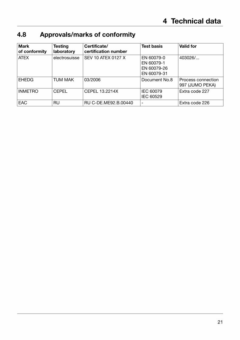
4.8 Approvals/marks of conformity
Mark of conformity
Testing laboratory
Certificate/certification number
Test basis Valid for
ATEX electrosuisse SEV 10 ATEX 0127 X EN 60079-0EN 60079-1EN 60079-26EN 60079-31
403026/...
EHEDG TUM MAK 03/2006 Document No.8 Process connection 997 (JUMO PEKA)
INMETRO CEPEL CEPEL 13.2214X IEC 60079IEC 60529
Extra code 227
EAC RU RU C-DE.ME92.B.00440 - Extra code 226
21

4 Technical data
22

5 Mounting
5.1 Before mounting
5.2 Unscrewing the front ring or housing coverThe front ring and rear housing cover can be unscrewed once the locking screws (1) havebeen released. A 1.5AF hex key is required to release the locking screws.
DANGER!
The system must be depressurized before mounting the JUMO dTRANS p20 Ex d pressure transmitter!
In potentially explosive atmospheres, only open the pressure transmitter once it has been de-energized!
NOTE!
The installation location should be easily accessible, if possible in the vicinity of themeasuring point, and low in vibration. The permissible ambient temperature must bemaintained (note any possible heat radiation).
The JUMO dTRANS p20 Ex d pressure transmitter can be mounted above or below thepressure tapping point.
NOTE!
Use a screwdriver, or similar, for unscrewing.
Only tighten by hand!
(1)
23

5 Mounting
5.3 Rotating the LCD (display)
Installation position
The nominal position of the JUMO dTRANS p20 Ex d pressure transmitter is standingvertically.
Depending on the specific features of the measuring point, the pressure transmitter can beinstalled in any other position. The LCD display can be rotated in 90° increments to reach thepreferred installation position.
✱ Unscrew the front ring, see chapter 5.2 "Unscrewing the front ring or housing cover", page 23.
✱ Pry out the electronics module with a narrow (small) screwdriver.
✱ Rotate the electronics module to the preferred position (in 90° increments) and reinsert it.
✱ Screw on the front ring finger-tight.
✱ Securely tighten the locking screw.
24

5 Mounting
5.4 Rotating the enclosureThe enclosure can be rotated ± 160°
✱ Loosen the threaded pin with a 1.5 mm AF hex key (about 1/2 revolution is sufficient).
✱ Rotate the enclosure to the preferred position.
✱ Retighten the threaded pin securely.
25

5 Mounting
5.5 Pressure connection
Seals
Operating conditions (for example material compatibility) must be considered when selectingthe seal.
Tightening torques
Maximum 200 Nm.
The correct tightening torque depends on the size, material and shape of the seal that is usedand the pressure connection of the pressure transmitter.
Check for leaks
If the pressure connection is made, it must be checked for leaks.
CAUTION
Improper operation of the shut-off fittings can result in physical injury or cause considerable damage to equipment!
Follow the specified order for opening and closing valves!
For use in toxic media the device must not be vented!
NOTE!
Depending on the system configuration, the following examples must be adapted to meetrequirements!
26

5 Mounting
5.6 Measuring relative or absolute pressure
Gases
Pressurization
Starting position: all valves closed.
Activate the shut-off fittings in the following order:
✱ Open the shut-off valve (4) on the pressure tapping support.✱ Open the shut-off valve (2A).✱ Check the range start.✱ Close the shut-off valve (2A).✱ Open the shut-off valve (2B).✱ Use the test connection of the shut-off fitting (2) to apply pressure corresponding to the
range start, to the transmitter.✱ Check the output current at range start (P2 mA) and correct if necessary,
see chapter 7.3.2 "The parameter level", page 41.✱ Close the shut-off valve (2B).✱ Open the shut-off valve (2A)
Transmitter above the pressure tapping point (normal arrangement)
Transmitter below the pressure tappingpoint (exception)
(1) Transmitter (2) Shut-off fitting2 A Shut-off valve to the process2 B Shut-off valve for the test connection
(3) Pressure line (4) Shut-off valve(5) Shut-off valve (optional) (6) Condensation valve (optional)(7) Outlet valve
2
1
3
4
2A2B
5
2
1
6
3
4
2A2B
7
27
5 Mounting
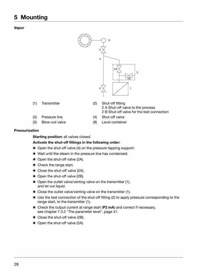
Vapor
Pressurization
Starting position: all valves closed.
Activate the shut-off fittings in the following order:
✱ Open the shut-off valve (4) on the pressure tapping support.
✱ Wait until the steam in the pressure line has condensed.
✱ Open the shut-off valve (2A).
✱ Check the range start.
✱ Close the shut-off valve (2A).
✱ Open the shut-off valve (2B).
✱ Open the outlet valve/venting valve on the transmitter (1),and let out liquid.
✱ Close the outlet valve/venting valve on the transmitter (1).
✱ Use the test connection of the shut-off fitting (2) to apply pressure corresponding to the range start, to the transmitter (1).
✱ Check the output current at range start (P2 mA) and correct if necessary,see chapter 7.3.2 "The parameter level", page 41.
✱ Close the shut-off valve (2B).
✱ Open the shut-off valve (2A).
(1) Transmitter (2) Shut-off fitting2 A Shut-off valve to the process2 B Shut-off valve for the test connection
(3) Pressure line (4) Shut-off valve(5) Blow-out valve (8) Level container
2A
5
3
4
2B
2
1
8
28

5 Mounting
Liquids
Pressurization
Starting position: all valves closed.
Activate the shut-off fittings in the following order:
✱ Open the shut-off valve (4) on the pressure tapping support.
✱ Open the shut-off valve (2A).
✱ Check the range start.
✱ Close the shut-off valve (2A).
✱ Open the shut-off valve (2B).
✱ Open the outlet valve/venting valve on the transmitter (1) and let out liquid.
✱ Close the outlet valve/venting valve on the transmitter (1).
✱ Use the test connection of the shut-off fitting (2) to apply pressure corresponding to the range start, to the transmitter (1).
✱ Check the output current at range start (P2 mA) and correct if necessary,see chapter 7.3.2 "The parameter level", page 41.
✱ Close the shut-off valve (2B).
✱ Open the shut-off valve (2A).
(1) Messumformer (2) Shut-off fitting2A Shut-off valve to the process2B Shut-off valve for the test connection
(3) Pressure line (4) Shut-off valve(5) Blow-out valve
9
2
1
6
3
4
2A2B
29
5 Mounting
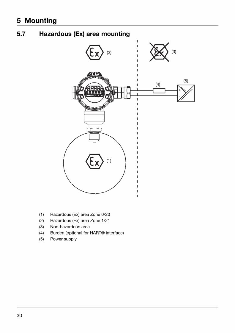
5.7 Hazardous (Ex) area mounting
(1) Hazardous (Ex) area Zone 0/20(2) Hazardous (Ex) area Zone 1/21(3) Non-hazardous area(4) Burden (optional for HART® interface)(5) Power supply
+-
(2)
(1)
(3)
(4)(5)
30

6 Installation
6.1 Installation instructions
General
Applicable requirements must be followed for the electrical connection, especially in apotentially explosive atmosphere:
• Regulation concerning electrical systems in areas with an explosion hazard (Elex V).
• Requirement for project planning, selecting and setting up electrical systems in areas with an explosion hazard (IEC 60079-14).
• EC-type examination certificate
• Electromagnetic compatibility meets the requirements of EN 61326.
• Apart from faulty installation, incorrect settings on the device may also affect the proper functioning of the subsequent process or lead to damage. You should therefore always provide safety equipment that is independent of the device and it should only be possible for qualified personnel to make settings.
Conductor cross-sections and ferrules
DANGER!In potentially explosive atmospheres, only open the pressure transmitter once it hasbeen de-energized!The electrical connection must only be implemented by suitably qualified personnel!Ground the device!Only use cable entries or glands, blanking plugs, etc., that are suitable for the "explosion-proof enclosure d" protection type!
The cables or leads must be suitable for the ambient conditions!
Connection openings on the device that are open must be closed with suitable blanking plugs!
Permissible cross-sectionWithout ferrule(for rigid cable only)
0.2 to 1.5 mm2
AWG 24 to 16With ferrule(for rigid or flexible cable)
0.25 to 0.75 mm2
31
6 Installation
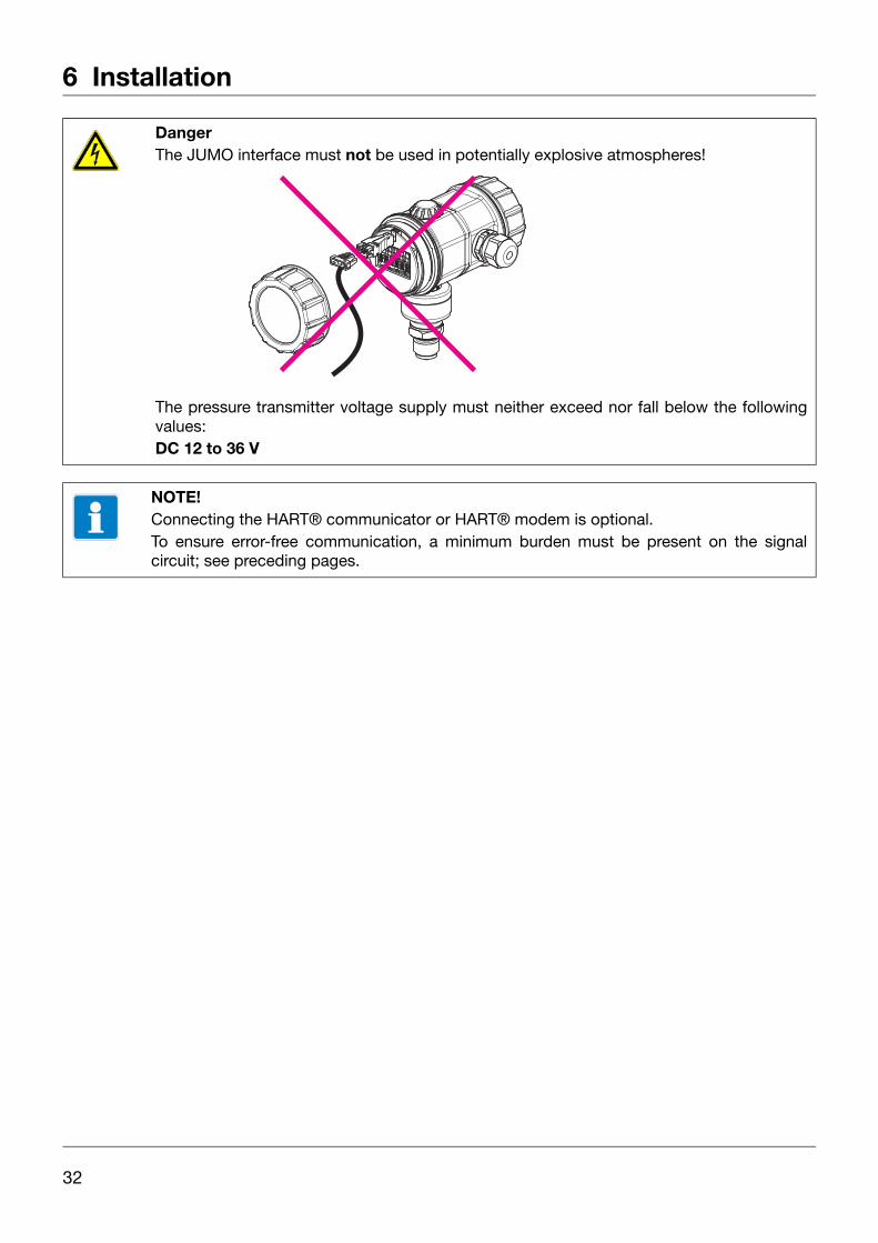
DangerThe JUMO interface must not be used in potentially explosive atmospheres!
The pressure transmitter voltage supply must neither exceed nor fall below the followingvalues:DC 12 to 36 V
NOTE!Connecting the HART® communicator or HART® modem is optional.To ensure error-free communication, a minimum burden must be present on the signalcircuit; see preceding pages.
32

6 Installation
6.1.1 Connection diagram
(1) Hazardous (Ex) area Zone 0/21(2) Hazardous (Ex) area Zone 1/21(3) Non-hazardous area(4) Burden for HART® (UB-12 V) ÷ 0.022 A in addition:
min. 250 , max. 1100 (5) Power supply DC 12 to 36 V(6) Indicator or recorder, controller, PLC, etc.(7) Additional devices(8) HART® modem(9) PC or notebook
+-
(1)
(2) (3)
(4)
(6)
(5)
(7)
(9)(8)
33

6 Installation
6.2 Cable gland
General information
• The cables or leads must be suitable for the ambient conditions
• Permissible cable diameters range from 7.5 to 11.9 mm
• Max. wire cross-section 1.5mm2
• Keep signal leads separate from cables with voltages of 60 V
• Use a shielded cable with twisted wires
• Avoid the vicinity of large electrical systems
• The full specification as per HART® Version 5.1, will only be achieved with a shielded cable.
(1) The connecting cable must extend at least 5 mm into the enclosure(2) Tighten the screw fitting by hand until you encounter resistance(3) Tighten the screw connection about 3/4 revolution with a wrench
3
1
2
34

6 Installation
Connection
✱ Unscrew the housing cover from behind.siehe Kapitel 5.2 "Unscrewing the front ring or housing cover", Seite 23.
✱ To connect the connecting cables, see the following illustration.
Terminal assignment
CAUTION!Once electrical connection is complete, re-tighten the locking screw of the housing cover!
Connection Terminal assignmentPower supplyDC 12 to 36 V
1 L+2 L-
Output4 to 20 mA, two-wires
Impressed current 4 to 20 mA in power supply
1 L+
2 L-
Current output test connection
Internal ammeter resistance 10 TEST +TEST -
HART® test connection
The burden must be present!
HART +HART -
Functional ground 3
Grounding or equipotential bonding outside, on the enclosure
35

6 Installation
Operation and test
(1) Total burden: Burden (UB-12 V) ÷ 0.022 A;
for HART® in addition: min. 250 , max. 1100 (2) Indicator or recorder, controller, PLC, etc.(3) Voltage supply: DC 12 to 36 V(4) HART® modem(5) PC or notebook
2 31
+ -
HART -
HART +
Test +
Test -
+-
(1)(2)
(3)
(4)(5)
36
7 Operation
7.1 Display
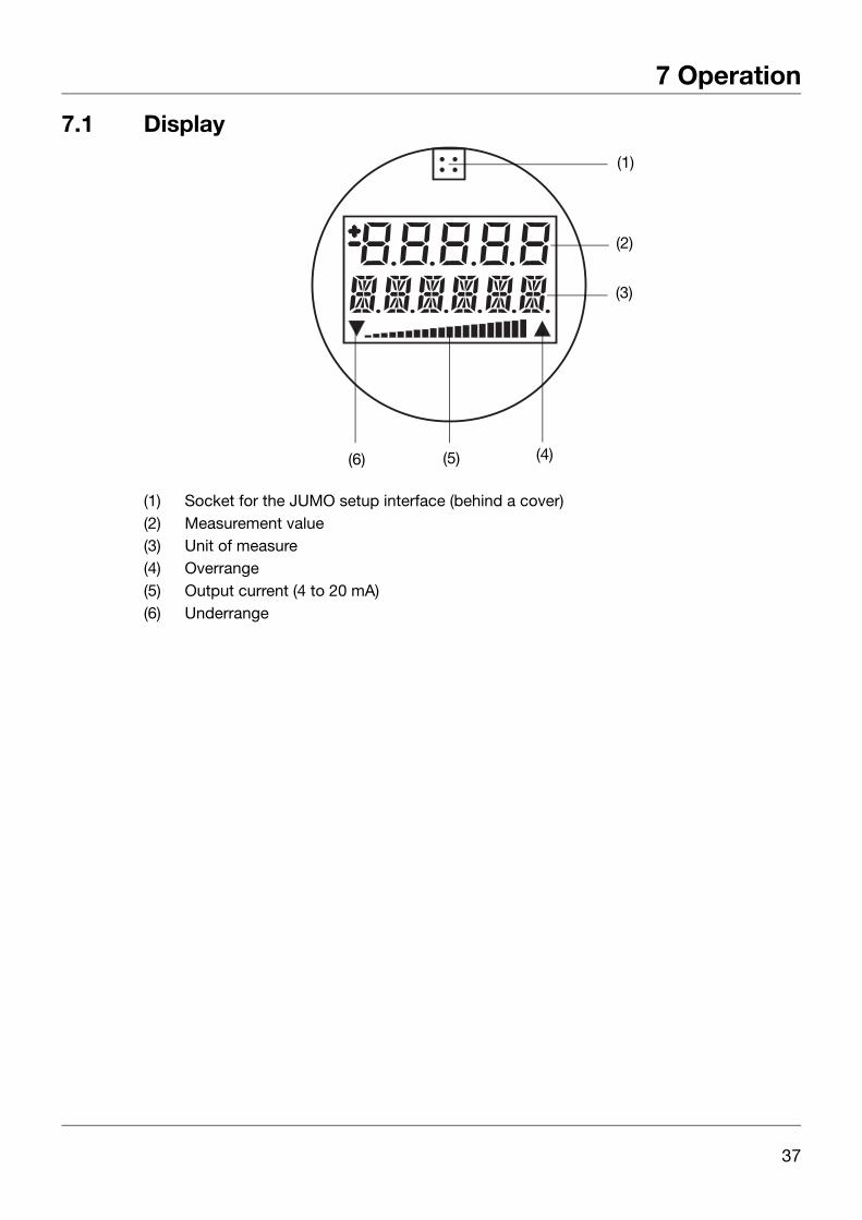
(1) Socket for the JUMO setup interface (behind a cover)(2) Measurement value(3) Unit of measure(4) Overrange (5) Output current (4 to 20 mA)(6) Underrange
(1)
(2)
(3)
(4)(5)(6)
37
7 Operation
7.2 Operation with rotary knob or with setup program
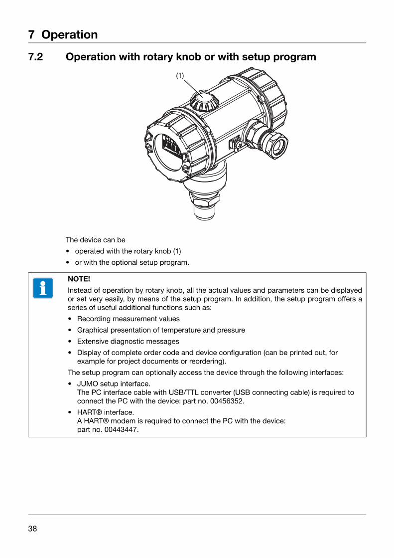
The device can be
• operated with the rotary knob (1)
• or with the optional setup program.
(1)
NOTE!
Instead of operation by rotary knob, all the actual values and parameters can be displayedor set very easily, by means of the setup program. In addition, the setup program offers aseries of useful additional functions such as:
• Recording measurement values
• Graphical presentation of temperature and pressure
• Extensive diagnostic messages
• Display of complete order code and device configuration (can be printed out, for example for project documents or reordering).
The setup program can optionally access the device through the following interfaces:
• JUMO setup interface.The PC interface cable with USB/TTL converter (USB connecting cable) is required to connect the PC with the device: part no. 00456352.
• HART® interface.A HART® modem is required to connect the PC with the device:part no. 00443447.
38
7 Operation
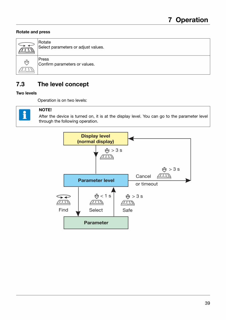
Rotate and press
7.3 The level conceptTwo levels
Operation is on two levels:
RotateSelect parameters or adjust values.
PressConfirm parameters or values.
NOTE!
After the device is turned on, it is at the display level. You can go to the parameter levelthrough the following operation.
39

7 Operation
7.3.1 The display level
The measured pressure and other parameters are shown at display level. The output current is shown as a percentage in a bar diagram on the third line of the display.It is not possible to change the parameters at display level!
Action Display(example)
Explanation
Display of pressure with unit of measure.
Display of measurement value as a %
or
Measurement value scaled with a freely selectable unit of measure.Display of output current in mA.
Display of sensor temperature in °C or °F.
Display of the saved minimum pressure in the selected unit of measure.
Display of the saved maximum pressure.
Display of the pressure value and sensor temperature in the selected unit of measure.
40

7 Operation
7.3.2 The parameter level
Device parameters can be displayed and changed at parameter level.
Action Display(example)
Explanation Selection1
P min
Saved minimum pressure
Reset by
> 3 seconds
P max
Saved maximum pressure
Reset by
> 3 seconds
P0 Den
"Density" density correction
0.01 to 1.00 to 99.99
P1 Uni
"Unit" unit of measure for pressure
inH2OinHGftH2OmmH2OmmHGPSIbarmbarkg/cm2kPaTORRMPamH2O
P2 mA
Range start current
4.00 to 20.00 mA
P3 mA
Range end current
4.00 to 20.00 mA
P4 sec
Damping
0.0 to 100.0 s
P5 RS
Range start
Nominal measuring range
41

7 Operation
P6 RE
Range end
Nominal measuring range
P7 Zero
Zero-point adjustment
Current pressure
P8 mA
Current sensor
3.60 to 4.00 to 21.60 mA
P9 Err
Current in case of error
ErLo = 3.6 mA
ErHi = 21.6 mA
LASt = Last value
P10 Key
Operator lockout
O = No lock
LA = All, interface free
LO = All, without range start
LS = All, without range start and end
LALL = All, incl. interface
P11 Chr
"Characteristic" curve
Lin = Linear
SLin = Linear until start of root extraction
SoFF = Off until start of root extraction
P12 %
Point at which root extraction begins
5.0 to 9.4 to 15.0% of output current
P13 SWV
Software version
Editing not possible
P14 Uni
Unit of measure for temperature
°C / °F
P15 OFF
Pressure value offset(zero point offset)
Nominal measuring range
Action Display(example)
Explanation Selection1
42

7 Operation
P16 SCS
Scaling start
-9999 to 0 to 9999
P17 SCE
Scaling end
-9999 to 100 to 9999
P18 SCD
Scaling decimal point
Auto = automatic
0 = no places after decimal point
1 = 1 place after decimal point
2 = 2 places after decimal point
3 = 3 places after decimal point
P19 %
Unit for scaling
% (factory setting)kg/seckg/minkg/ht/mint/hl/secl/minl/hm3/secm3/minm3/hLm3UsrTXT
P20 h
Operating hours
Editing not possible
1 Factory setting is shown in bold.
Action Display(example)
Explanation Selection1
43

7 Operation
44

8 Maintenance
8.1 Eliminating errors and faults
NOTE!
If you determine an external defect – also a mechanical way – the differential pressuretransmitter has to be sent for repair to the manufacturer.
Error/fault Possible cause Remedy
Display: none No voltage supply Turn on the voltage supply
Device faulty Send the device to the supplier for repairs
Display: Overrange,overpressure
Bring the pressure back into the measuring range or adjust the mea-suring rangeDisplay: Underrange,
underpressure
Display: Pressure can no longer be dis-played, overpressure
Adjust scaling or unit of measureDisplay: Pressure can no longer be dis-
played, underpressure
Display: The connection between sensor and electronic is broken
a) Proof the plug connection at the back of the electronic module
b) Send the device to the supplier for repairs
Display: An error was discovered in the electronics during the self test
Send the device to the supplier for repairs
Display: Temperature sensor faulty Send the device to the supplier for repairs
45

8 Maintenance
The rotary knob is not responding
Keyboard lock Override keyboard lock
Device faulty Send the device to the supplier for repairs
46
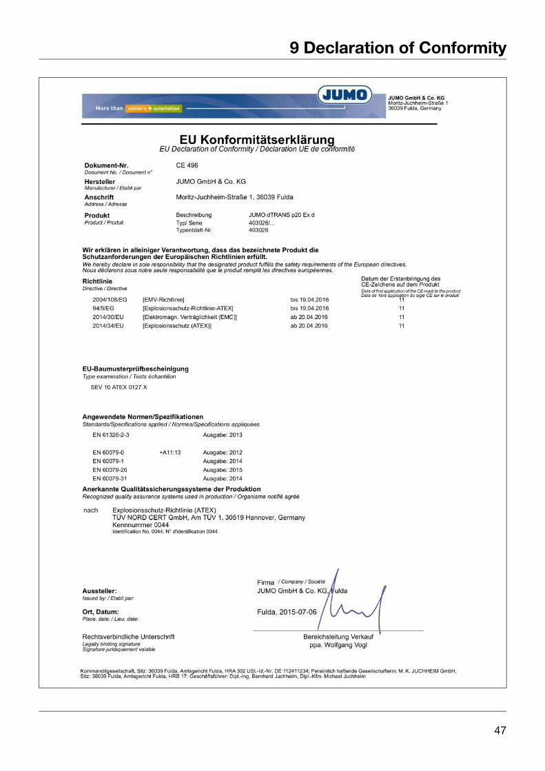
9 Declaration of Conformity
47

9 Declaration of Conformity
48
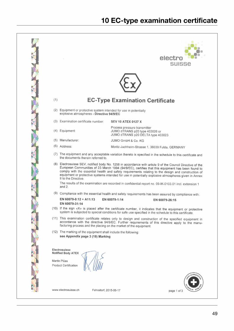
49
10 EC-type examination certificate

10 EC-type examination certificate
50
51
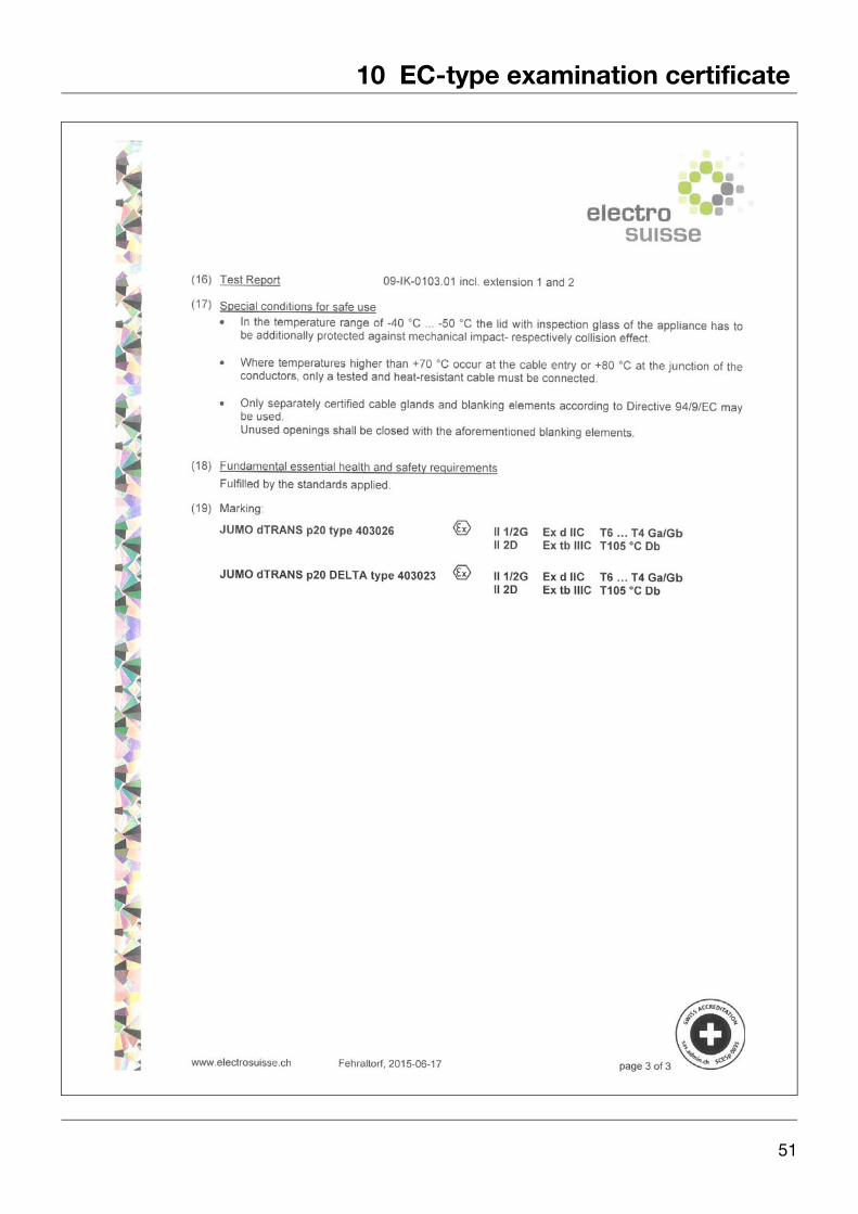
10 EC-type examination certificate

10 EC-type examination certificate
52

11 China RoHS
������������ �����
��
��
��
��
��
��
��
��
��
�
�������������������
���
��
������
���
���
����!�
�"�#$����
��������������!��
������������#%����
� &��
�'������
(���)
�(�#������
��
��
�
����
����
��
� ��
����
�����
�����
����
����
����
����
����
����
����
�����
����
�����
������
����
��
���
�� !
"#$
����
%&�
��"
'�(��
�����
�����
�����
����
)���
�*���
*���
����
�����
����
����
�����
�����
����
+�,
����
*��+
����
�����
�����
�����
����
�����
����
�����
��+���
��-*
���+
�����
��#$�
���
%&�
!.
#$��
��%
&��
�.'�(
�����
�����
�����
����
��)�
���*
���*�
����
�����
����
����
����
����
�����
���+
�,��
��*�
�+��
����
����*
����
�����
�����
�����
�����
�����
����+
�����
-*���
+��
�����#
$���
�%&
� !
53

11 China RoHS
54


JUMO GmbH & Co. KG JUMO Instrument Co. Ltd. JUMO Process Control, Inc.Street address:Moritz-Juchheim-Straße 136039 Fulda, GermanyDelivery address:Mackenrodtstraße 1436039 Fulda, GermanyPostal address:36035 Fulda, GermanyPhone: +49 661 6003-0Fax: +49 661 6003-607Email: [email protected]: www.jumo.net
JUMO HouseTemple Bank, RiverwayHarlow, Essex CM 20 2DY, UKPhone: +44 1279 63 55 33Fax: +44 1279 62 50 29Email: [email protected]: www.jumo.co.uk
6733 Myers RoadEast Syracuse, NY 13057, USAPhone: +1 315 437 5866Fax: +1 315 437 5860Email: [email protected]: www.jumousa.com