processmaster fep500 electromagnetic flowmeter the process ... · instrumentation for industrial...
TRANSCRIPT

Data Sheet DS/FEP500-EN
ProcessMaster FEP500 Electromagnetic Flowmeter
The process industry's first choice
Intuitive operation — Softkey-based functionality — “Easy Set-up” function Diagnostics for real-life situations — Status messages in accordance with NAMUR — Help texts in the display Extended diagnostic functions — Electrode deposit detection — Gas bubble detection — Partial filling detection — Conductivity monitoring — Sensor temperature monitoring — Trend analysis Batch functionality — Presetting counter, overrun correction, external start/stop,
batch end contact
Maximum measuring accuracy — Maximum measuring error: 0.2 % of rate Universal transmitter — Reduces spare parts inventory costs and storage costs Flowmeter sensor featuring state-of-the-art memory technology — Prevents errors and enables quick and reliable
commissioning Approvals for explosion protection — In accordance with ATEX, IECEx — In accordance with FM, cFM HART, PROFIBUS PA, FOUNDATION Fieldbus — Access to all status information
Change from one to two columns

Electromagnetic Flowmeter ProcessMaster FEP500 DS/FEP500-EN
2
ABB ABB is an established world force in the design and manufacture of instrumentation for industrial process control. Worldwide presence, comprehensive service and application-oriented know-how make ABB a leading supplier of flow measurement products.
Introduction The industrial standard ProcessMaster is designed specifically to meet the increased requirements on advanced flowmeters. The modular design concept offers flexibility, cost-saving operation and reliability whilst providing a long service life and exceptionally low maintenance. Integration into ABB asset management systems and usage of the self-monitoring and diagnostic functions increase the plant availability and reduce downtimes.
Advanced diagnostic functions Using its advanced diagnostic functions, the device monitors both its own operability and the process. Limit values for the diagnostic parameters can be set locally. When these limits are exceeded, an alarm is tripped. For further analysis, the diagnostic data can be read out via an advanced DTM. Critical states can, thus, be recognized early and appropriate measures can be taken. As a result, productivity is increased and downtimes are avoided. The status messages are classified in accordance with the NAMUR recommendations. In the event of an error, a diagnostic-dependent help text appears on the display which considerably simplifies and accelerates the troubleshooting procedure. The gives maximum safety for the process.
Superior and reliable new flowmeter sensor design Self-cleaning, double-sealed polished measuring electrodes enhance the device's reliability and performance. Using a higher excitation frequency for the transmitter, ProcessMaster is a flowmeter with an especially short response time. With its advanced filtering methods, the device improves accuracy even under difficult conditions by separating the noise from the measuring signal. This leads to a max. measuring error of 0.2 % of rate.
Easy and quick commissioning Advanced data storage inside the sensor eliminates the need to match sensor and transmitter in the field. The on-board sensor memory automatically identifies the transmitter. On power-on, the transmitter self-configuration function is run. and replicates all sensor data and TAG-specific parameters into the transmitter. This eliminates the opportunity for errors and leads to an increased startup speed and reliability.
Intuitive, convenient navigation The factory-set parameters can be modified quickly and easily via the user-friendly display and the non-contact buttons, without opening the housing. The "Easy Set-up" function reliably guides unpracticed users through the menu step by step. The softkey-based functionality makes handling a breeze - it's just like using a cell phone. During the configuration, the permissible range of each parameter is indicated on the display and invalid entries are rejected.
Universal transmitter - powerful and flexible The backlit display can be easily rotated without the need for any tools. The contrast is adjustable and the display fully configurable. The character size, number of lines and display resolution (number of decimals) can be set as required. In multiplex mode, several different display options can be pre-configured and invoked one after the other. The smart modular design of the transmitter unit allows for easy disassembly without the need to unscrew cables or unplug connectors. Whether count pulses, 20 mA signals or the status output are active or passive, the universal transmitter always delivers the correct signal. HART is used as the standard protocol. Optionally, the transmitter is available with PROFIBUS PA or FOUNDATION Fieldbus communication. The universal transmitter simplifies the spare parts inventory and reduces the stockholding costs.
ScanMaster - the diagnostic tool Can I rely on the measured values? How can I determine the technical condition of my device? ScanMaster can answer these frequently asked questions. And ScanMaster allows you to easily check the device for proper functioning.
ProcessMaster - always the first choice ProcessMaster sets the standard for the process industry. It meets the various requirements of NAMUR. ProcessMaster is a universal device according to the Pressure Equipment Directive. In compliance with the requirements of NAMUR, the devices are categorized under category III for pipelines. As a result, ProcessMaster can be used universally. This reduces costs and increases safety.
Overview of the ProcessMaster series ProcessMaster is available in two series. ProcessMaster 300 with basic functionality and ProcessMaster 500 with extended functions and options. The following table gives an overview.
ProcessMaster FEP300 FEP500 Measuring accuracy 0.4 % (optionally 0.2 %) of rate X - Measuring accuracy 0.3 % (optionally 0.2 %) of rate - X Batch functions Presetting counter, overrun correction, external start/stop, batch end contact
- X
Other software functions Mass units, editable counter, X X Two measuring ranges - X Graphic display Line recorder function X X Diagnostic functions Detection of gas bubbles or deposits on electrodes, conductivity monitoring, temperature monitoring, finger print, trend
- X
Partially filled Recognition through partial filling electrode (TFE) X X Hardware options Versions for extremely abrasive fluids: • Ceramic carbide liner, • Tungsten carbide electrodes, • Double layer electrodes
- X
Startup functions Grounding check - X Fieldbus PROFIBUS PA, FOUNDATION Fieldbus X X Verifications / Diagnostic tool ScanMaster X X
This data sheet describes ProcessMaster 500. For ProcessMaster 300 refer to data sheet DS/FEP300. Change from one to two columns
Contents

Electromagnetic Flowmeter ProcessMaster FEP500 DS/FEP500-EN
3
Contents 1 ProcessMaster 500 - Overview of technology..................................................................................................5 2 Performance specifications ...............................................................................................................................7
2.1 General...........................................................................................................................................................7 2.2 Reproducibility, response time .......................................................................................................................7 2.3 Transmitter .....................................................................................................................................................7 2.4 Flowmeter sizes, flow range...........................................................................................................................8 2.5 Filling function (batch) ....................................................................................................................................9
3 Extended diagnostic functions ........................................................................................................................10 3.1 General.........................................................................................................................................................10
4 Functional specifications .................................................................................................................................14 4.1 Flowmeter sensor.........................................................................................................................................14 4.2 Electrical connection ....................................................................................................................................19
5 Ex-relevant specifications for operation in zones 1, 21, 22 / Div. 1 .............................................................25 5.1 General.........................................................................................................................................................25 5.2 Electrical connection ....................................................................................................................................26 5.3 Electrical data for operation in Zone 1 / Div. 1 .............................................................................................30 5.4 Temperature values .....................................................................................................................................32 5.5 Special features of version designed for operation in Ex zone 1 / Div. 1.....................................................35
6 Ex-relevant specifications for operation in zones 2, 21, 22 / Div. 2 .............................................................37 6.1 General.........................................................................................................................................................37 6.2 Electrical connection ....................................................................................................................................38 6.3 Electrical data for operation in Zone 2 / Div. 2 .............................................................................................40 6.4 Temperature values .....................................................................................................................................40
7 Explosion protection specifications for operation in areas with combustible dust ..................................44 7.1 Information about using the device in areas with combustible dust.............................................................44
8 Installation requirements..................................................................................................................................45 8.1 Grounding.....................................................................................................................................................45 8.2 Mounting.......................................................................................................................................................45
9 Dimensions ........................................................................................................................................................47 9.1 Flange, DN 3 ... 125 (1/10 ... 5") ..................................................................................................................47 9.2 Flange DN 150 ... 400 (6 ... 16") ..................................................................................................................49 9.3 Flange DN 450 ... 2000 (18 ... 80") ..............................................................................................................51 9.4 Flange DN 15 ... 200 (1/2 ... 8"), high-pressure versions PN 63 and PN 100 .............................................53 9.5 Flange DN 15 ... 200 (1/2 ... 8"), high-pressure version CL 600..................................................................55 9.6 Flowmeter sensor model FET521 and FET525 zone 2, Div 2 .....................................................................56 9.7 Transmitter housing for model FET525 for Ex zone 1 / Div. 1 .....................................................................56
10 Ordering information.........................................................................................................................................57 10.1 ProcessMaster FEP511, FEP515 electromagnetic flowmeter, compact design..........................................57 10.2 ProcessMaster FEP521, FEP525 electromagnetic flowmeter, remote mount design.................................61

Electromagnetic Flowmeter ProcessMaster FEP500 DS/FEP500-EN
4
10.3 FET521, FET525 external transmitter for ProcessMaster ...........................................................................65 10.4 FET501 transmitter plug-in module for ProcessMaster/HygienicMaster .....................................................67 10.5 FXC4000 flowmeter sensor simulator ..........................................................................................................67 10.6 Diagnostic and verification software - ScanMaster FZC500........................................................................68 10.7 Infrared service port adapter type FZA100 ..................................................................................................68 10.8 Installation set for 2" pipe installation in field-mount housing ......................................................................68
Data Sheet Electromagnetic Flowmeter
ProcessMaster FEP500

Electromagnetic Flowmeter ProcessMaster FEP500 DS/FEP500-EN
5
110
1 ProcessMaster 500 - Overview of technology
Model overview (compact design) FEP511 (without explosion
protection) FEP515 (explosion protection Zone 2 / Div.2) FEP515 (explosion protection Zone 1 / Div. 1)
G00886 ATEX / IEC ATEX / IEC Gases Zone 2 Gases Zone 1 Dust Zone 21, 22 Dust Zone 21, 22 FM / cFM FM / cFM CL I Div 2 (NI, DIP) CL I Div 1, 2 (XP, NI, DIP) For further information about the instruments' explosion protection approval please refer to the Ex test
certificates (available on the product CD or under www.abb.com/flow).
Model number FEP511, FE515 Measured value error Standard: 0.3 % of rate
Optional: 0.2 % of rate Nominal size range DN 3 ... 2000 (1/10 “ ... 80 ") Process connection Flange in accordance with DIN 2501/EN 1092-1,
ASME B16.5/B16.47, JIS 10K Nominal pressure PN 10 … 100, ASME CL 150, 300, 600 Lining Hard rubber (DN 15 ... 2000), soft rubber (DN 50 ... 2000), PTFE (DN 10 ... 600),
PFA (DN 3 ... 200), ETFE (DN 25 ... 1000), Elastomer (DN 50 ... 600), Ceramic Carbide (DN 25 ... 1000) under preparation
Conductivity > 5 µS/cm (20 µS/cm for demineralized water) Electrodes Stainless steel, Hastelloy B, Hastelloy C, platinum-iridium, tantalum, titanium,
Double Layer under preparation, Wolfram carbide under preparation Process connection material Steel, stainless steel Ingress protection IP 65, IP 67 Medium temperature -25 ... 180 °C (-13 ... 356 °F) Approvals Explosion protection approvals ATEX / IECEx Zone 1, 2 , 21, 22
FM / cFM Cl 1 Div 1, Cl 1 Div 2 Pressure Equipment Directive 97/23/EC Conformity assessment in accordance with category III, fluid group 1 CRN (Canadian Reg. Number) On request Transmitter Supply power AC 100 ... 230 V (-15 / +10%), AC 24 V (-30 / +10%), DC 24 V (-30 / +30%) Current output 4 ... 20 mA, active or passive Impulse output Can be configured locally as active or passive using software Switch output Optocoupler, programmable function Contact input Optocoupler, programmable function Display Graphical display, configurable Housing Integral mount design Communication HART protocol (standard), PROFIBUS PA, FOUNDATION Fieldbus (option)
For food and beverage and pharmaceutical applications, refer to the HygienicMaster 500 data sheet

Electromagnetic Flowmeter ProcessMaster FEP500 DS/FEP500-EN
6
Model overview (remote mount design)
Flowmeter sensor FEP521
(without explosion protection)
FEP525 (explosion protection Zone 2 / Div.) 2)
FEP525 (explosion protection Zone 1 / Div.) 1)
G00862 ATEX / IEC ATEX / IEC Gases Zone 2 Gases Zone 1 Dust Zone 21, 22 Dust Zone 21, 22 FM / cFM FM / cFM CL I Div 2 (NI, DIP) CL I Div 1, 2 (XP, NI, DIP)
For further information about the instruments' explosion protection approval please refer to the Ex test certificates (available on the product CD or under www.abb.com/flow).
Transmitter FET521
(without explosion protection)
FET525 (explosion protection Zone
2, Div.) 2)
FET521 (without
explosion protection)
FET525 (explosion protection Zone 1,
Div. 1)
FET525 (explosion protection Zone
2, Div. 2)
FET521 (without
explosion protection)
G00863 ATEX / IEC ATEX / IEC ATEX / IEC Gases Zone 2 Gases Zone 1 Gases Zone 2 Dust Zone 21, 22 Dust Zone 21, 22 Dust Zone 21, 22 FM / cFM FM / cFM FM / cFM CL I Div 2 (NI, DIP) CL I Div 1, 2 (XP, NI, DIP) CL I Div 2 (NI, DIP)
For further information about the instruments' explosion protection approval please refer to the Ex test certificates (available on the product CD or under www.abb.com/flow).
Flowmeter sensor FEP521, FEP525 Measured value error Standard: 0.3 % of rate
Optional: 0.2 % of rate). Nominal size range DN 3 ... 2000 (1/10 “ ... 80 “) Process connection Flange in accordance with DIN 2501 / EN 1092-1,
ASME B16.5 / B16.47, JIS 10K Nominal pressure PN 10 … 100, ASME CL 150, 300, 600 Lining Hard rubber (DN 15 ... 2000), soft rubber (DN 50 ... 2000), PTFE (DN 10 ... 600),
PFA (DN 3 ... 200), ETFE (DN 25 ... 1000), Elastomer (DN 50 ... 600), Ceramic Carbide (DN 25 ... 1000) under preparation
Conductivity > 5 µS/cm (20 µS/cm for demineralized water) Electrodes Stainless steel, Hastelloy B, Hastelloy C, platinum-iridium, tantalum, titanium, Double Layer
under preparation, Wolfram carbide under preparation Process connection material Steel, stainless steel Ingress protection IP 65, IP 67, IP 68, (NEMA 4X) Medium temperature -25 ... 180 °C (-13 ... 356 °F) Approvals Explosion protection approvals ATEX/IECEx Zone 1, 2, 21, 22
FM / cFM Cl 1Div 1, Cl 1 Div 2 Pressure Equipment Directive 97/23/EC Conformity assessment in accordance with category III, fluid group 1 CRN (Canadian Reg. Number) On request Transmitter FET521, FET525 Supply power AC 100 ... 230 V (-15 / +10%), AC 24 V (-30 / +10%), DC 24 V (-30 / +30%) Current output 4 ... 20 mA, active or passive Impulse output Can be configured locally as active or passive using software Switch output Optocoupler, programmable function Contact input Optocoupler, programmable function Display Graphical display, configurable Housing Remote mount design Communication HART protocol (standard), PROFIBUS PA, FOUNDATION Fieldbus (option)
For food and beverage and pharmaceutical applications, refer to the HygienicMaster 500 data sheet

Electromagnetic Flowmeter ProcessMaster FEP500 DS/FEP500-EN
7
2 Performance specifications Change from one to two columns A
2.1 General
2.1.1 Reference conditions according to EN 29104
Fluid temperature 20 °C (68 °F) ± 2 K Ambient temperature 20 °C (68 °F) ± 2 K Supply power Nominal voltage acc. to name
plate Un ± 1 %, frequency f ± 1 %
Installation conditions - Upstream >10 x DN, straight section
- Downstream >5 x DN, straight section
Warm-up phase 30 min.
2.1.2 Maximum measuring error
Impulse output - Standard calibration: ± 0.3 % of measured value, ± 0.02 % QmaxDN
(DN 3 … 600, 800) ± 0,4 % of measured value, ± 0,02 % QmaxDN
(DN 700, DN 900 … 2000) - Optional calibration: ± 0.2 % of measured value, ± 0.02 % QmaxDN
(DN 10 … 600, 800) QmaxDN: See table in Section 2.4, "Flowmeter sizes, flow range".
Fig. 1
Y Accuracy ± of measured value in [%] X Flow velocity v in [m/s], Q / QmaxDN [%]
Analog output effects Same as pulse output plus ± 0.1 % of measured value ± 0.01 mA
2.2 Reproducibility, response time
Reproducibility ≤ 0.11 % of measured value, tmeas = 100 s, v = 0.5 ... 10 m/s
Response time of current output with damping of 0.02 seconds
As step function 0 ... 99 % 5 τ ≥ 200 ms at 25 Hz excitation frequency 5 τ ≥ 400 ms at 12.5 Hz excitation frequency 5 τ ≥ 500 ms at 6.25 Hz excitation frequency
2.3 Transmitter
2.3.1 Electrical properties
AC 100 ... 230 V (-15 % / +10 %) AC 24 V (-30 % / +10 %)
Supply power
DC 24 V (-30 % / +30 %), ripple: < 5 %
Line frequency 47 ... 64 Hz Excitation frequency 6 1/4 Hz, 7 1/2 Hz, 12 1/2 Hz, 15 Hz,
25 Hz, 30 Hz (50 / 60 Hz power supply)
Power consumption (flowmeter sensor including transmitter) AC S ≤ 20 VA DC P ≤ 12 W (switch-on current
5.6 A) Electrical connection Screw terminals
2.3.1.1 Isolation of input/outputs The current output, digital outputs DO1 and DO2, and digital input are electrically isolated from the flowmeter sensor input circuit and from each other. The same is valid for the signal outputs of the versions with PROFIBUS PA and FOUNDATION Fieldbus.
2.3.1.2 Empty pipe detection The "empty pipe detection" function requires: A conductivity of the measured fluid ≥ 20 µS/cm, a signal cable length ≤ 50 m (164 ft), a nominal diameter DN ≥ DN 10, and the flowmeter sensor must not be provided with a preamplifier.
2.3.2 Mechanical properties
Integral mount design (transmitter mounted directly on the flowmeter sensor) Housing Cast aluminum, painted Paint Paint coat ≥ 80 µm thick, RAL 9002
(light gray) cable gland used Polyamide, stainless steel (version for
ambient temperature -40 °C (40 °F)) Remote mount design Housing Cast aluminum, painted Paint Paint coat ≥ 80 µm thick, mid-section
RAL 7012 (dark gray), front cover/rear cover RAL 9002 (light gray)
cable gland used Polyamide, stainless steel (version for ambient temperature -40 °C (40 °F))
Weight 4.5 kg (9.92 lb)
2.3.2.1 Storage temperature, ambient temperature Ambient temperature -20 ... 60 °C (-4 ... 140 °F) standard -40 ... 60 °C (-40 ... 140 °F) Advanced mode Storage temperature -40 ... 70 °C (-40 ... 158 °F)
2.3.2.2 Protection class for transmitter housing IP 65, IP 67, NEMA 4X
2.3.2.3 Vibration according to EN 60068-2 Transmitter • In the range 10 ... 58 Hz with max. 0.15 mm (0.006 inch) deflection* • In the range 58 ... 150 Hz max. 2 g acceleration* * = Peak load
Change from one to two columns

Electromagnetic Flowmeter ProcessMaster FEP500 DS/FEP500-EN
8
2.4 Flowmeter sizes, flow range
The flow range end value can be set between 0.02 x QmaxDN and 2 x QmaxDN.
Nominal diameter Min. flow range end value QmaxDN Max. flow range end value
DN " 0.02 x QmaxDN (≈ 0.2 m/s) 0 … ≈ 10 m/s 2 x QmaxDN (≈ 20 m/s) 3 1/10 0.08 l/min (0.02 US gal/min) 4 l/min (1.06 US gal/min) 8 l/min (2.11 US gal/min) 4 5/32 0.16 l/min (0.04 US gal/min) 8 l/min (2.11 US gal/min) 16 l/min (4.23 US gal/min) 6 1/4 0.4 l/min (0.11 US gal/min) 20 l/min (5.28 US gal/min) 40 l/min (10.57 US gal/min) 8 5/16 0.6 l/min (0.16 US gal/min) 30 l/min (7.93 US gal/min) 60 l/min (15.85 US gal/min)
10 3/8 0.9 l/min (0.24 US gal/min) 45 l/min (11.9 US gal/min) 90 l/min (23.78 US gal/min) 15 1/2 2 l/min (0.53 US gal/min) 100 l/min (26.4 US gal/min) 200 l/min (52.8 US gal/min) 20 3/4 3 l/min (0.79 US gal/min) 150 l/min (39.6 US gal/min) 300 l/min (79.3 US gal/min) 25 1 4 l/min (1.06 US gal/min) 200 l/min (52.8 US gal/min) 400 l/min (106 US gal/min) 32 1 1/4 8 l/min (2.11 US gal/min) 400 l/min (106 US gal/min) 800 l/min (211 US gal/min) 40 1 1/2 12 l/min (3.17 US gal/min) 600 l/min (159 US gal/min) 1200 l/min (317 US gal/min) 50 2 1.2 m3/h (5.28 US gal/min) 60 m3/h (264 US gal/min) 120 m3/h (528 US gal/min) 65 2 1/2 2.4 m3/h (10.57 US gal/min) 120 m3/h (528 US gal/min) 240 m3/h (1057 US gal/min) 80 3 3.6 m3/h (15.9 US gal/min) 180 m3/h (793 US gal/min) 360 m3/h (1585 US gal/min)
100 4 4.8 m3/h (21.1 US gal/min) 240 m3/h (1057 US gal/min) 480 m3/h (2113 US gal/min) 125 5 8.4 m3/h (37 US gal/min) 420 m3/h (1849 US gal/min) 840 m3/h (3698 US gal/min) 150 6 12 m3/h (52.8 US gal/min) 600 m3/h (2642 US gal/min) 1200 m3/h (5283 US gal/min) 200 8 21.6 m3/h (95.1 US gal/min) 1080 m3/h (4755 US gal/min) 2160 m3/h (9510 US gal/min) 250 10 36 m3/h (159 US gal/min) 1800 m3/h (7925 US gal/min) 3600 m3/h (15850 US gal/min) 300 12 48 m3/h (211 US gal/min) 2400 m3/h (10567 US gal/min) 4800 m3/h (21134 US gal/min) 350 14 66 m3/h (291 US gal/min) 3300 m3/h (14529 US gal/min) 6600 m3/h (29059 US gal/min) 400 16 90 m3/h (396 US gal/min) 4500 m3/h (19813 US gal/min) 9000 m3/h (39626 US gal/min) 450 18 120 m3/h (528 US gal/min) 6000 m3/h (26417 US gal/min) 12000 m3/h (52834 US gal/min) 500 20 132 m3/h (581 US gal/min) 6600 m3/h (29059 US gal/min) 13200 m3/h (58117 US gal/min) 600 24 192 m3/h (845 US gal/min) 9600 m3/h (42268 US gal/min) 19200 m3/h (84535 US gal/min) 700 28 264 m3/h (1162 US gal/min) 13200 m3/h (58118 US gal/min) 26400 m3/h (116236 US gal/min) 760 30 312 m3/h (1374 US gal/min) 15600 m3/h (68685 US gal/min) 31200 m3/h (137369 US gal/min) 800 32 360 m3/h (1585 US gal/min) 18000 m3/h (79252 US gal/min) 36000 m3/h (158503 US gal/min) 900 36 480 m3/h (2113 US gal/min) 24000 m3/h (105669 US gal/min) 48000 m3/h (211337 US gal/min)
1000 40 540 m3/h (2378 US gal/min) 27000 m3/h (118877 US gal/min) 54000 m3/h (237754 US gal/min) 1050 42 616 m3/h (2712 US gal/min) 30800 m3/h (135608 US gal/min) 61600 m3/h (271217 US gal/min) 1100 44 660 m3/h (3038 US gal/min) 33000 m3/h (151899 US gal/min) 66000 m3/h (290589 US gal/min) 1200 48 840 m3/h (3698 US gal/min) 42000 m3/h (184920 US gal/min) 84000 m3/h (369841 US gal/min) 1400 54 1080 m3/h (4755 US gal/min) 54000 m3/h (237755 US gal/min) 108000 m3/h (475510 US gal/min) 1500 60 1260 m3/h (5548 US gal/min) 63000 m3/h (277381 US gal/min) 126000 m3/h (554761 US gal/min) 1600 66 1440 m3/h (6340 US gal/min) 72000 m3/h (317006 US gal/min) 144000 m3/h (634013 US gal/min) 1800 72 1800 m3/h (7925 US gal/min) 90000 m3/h (396258 US gal/min) 180000 m3/h (792516 US gal/min) 2000 80 2280 m3/h (10039 US gal/min) 114000 m3/h (501927 US gal/min) 228000 m3/h (1003853 US gal/min)

Electromagnetic Flowmeter ProcessMaster FEP500 DS/FEP500-EN
9
2.5 Filling function (batch)
The integrated filling function of the device allows you to record filling processes >3 seconds. For this purpose, the filling quantity is given via an adjustable totalizer. Filling can be started via either the digital input or the fieldbus. The valve is triggered via one of the digital outputs and closed again once the preset filling quantity is reached. The transmitter measures the overrun quantity and calculates the overrun correction from this. Additionally, the low flow cut-off can be activated if required.
G01046
Q
t0
tvtn
M
12
4
5
O C
3
Fig. 2: 1 Supply tank 2 Start/stop contact (digital input) 3 Flowmeter sensor 4 Motor valve 5 Tank to be filled
O Valve open (filling started) C Valve closed (fill quantity reached) tv Valve closing time tn Overrun time

Electromagnetic Flowmeter ProcessMaster FEP500 DS/FEP500-EN
10
Change from one to two columns
3 Extended diagnostic functions
3.1 General
Important • When using the extended diagnostic functions the external flowmeter sensor must not be provided
with a preamplifier.
3.1.1 Detection of partial filling
Optionally, a measuring electrode (TFE electrode) is available for detecting a partially filled flowmeter sensor. The alarm for partial filling is output via the programmable digital output. Conditions for using the function:
• Nominal diameter from DN 50 (2“)
• Max. signal cable length for version with external transmitter 200 m (656 ft).
• Conductivity of the fluid: 20 μS/cm ... 20,000 μS/cm
• The function is only available for ProcessMaster 300 / 500 without explosion protection or with explosion protection for Zone 2 / Div 2.
Additional installation conditions:
• The flowmeter sensor must be installed horizontally with the terminal box pointing upward.
3.1.2 Detection of gas bubbles 1)
Gas bubbles in the fluid are detected by using an adjustable maximum limit value. When this limit value is exceeded, an alarm is tripped via the programmable digital output, depending on the configuration. Conditions for using the function:
• This function is available in the nominal diameter range 2) of DN 10 … 300 (3/8 “ ... 12 “).
• The signal cable length of the external transmitter must not exceed a maximum value of 50 m (164 ft) .
• For this function, the conductivity of the fluid must be in the range 20 μS/cm ... 20,000 μS/cm.
Additional installation conditions:
• The flowmeter sensor can be installed either horizontally or vertically. Vertical installation is preferred.
1) At present, the function is only available for devices without explosion protection or with explosion protection for
Zone 2 / Div. 2. For devices in Zone 1 / Div. 1 this function is under preparation (the function is already implemented in the software, but cannot be used for devices in Zone 1 / Div. 1).
2) The specified nominal diameter range is valid for ProcessMaster, only. The nominal diameter range valid for HygienicMaster is DN 10 … 100 (3/8 “ ... 4 “).

Electromagnetic Flowmeter ProcessMaster FEP500 DS/FEP500-EN
11
3.1.3 Detection of deposits on measuring electrodes 1)
This function provides the opportunity to detect deposits on the measuring electrodes by using an adjustable maximum limit value.
When the set limit value is exceeded, an alarm is tripped via the programmable digital output, depending on the configuration. Conditions for using the function:
• This function is available in the nominal diameter range 2) of DN 10 … 300 (3/8 “ ... 12 “).
• The signal cable length of the external transmitter must not exceed a maximum value of 50 m (164 ft) .
• For this function, the conductivity of the fluid must be in the range 20 μS/cm ... 20,000 μS/cm.
Additional installation conditions:
• When using plastic tubes, install a grounding plate at the front and back of the device.
3.1.4 Conductivity monitoring 1)
The conductivity of the fluid is monitored by using an adjustable minimum/maximum limit value.
When the value falls below or exceeds the set limit value, an alarm is tripped via the programmable digital output, depending on the configuration. Conditions for using the function:
• This function is available in the nominal diameter range 2) of DN 10 … 300 (3/8 “ ... 12 “).
• The signal cable length of the external transmitter must not exceed a maximum value of 50 m (164 ft) .
• For this function, the conductivity of the fluid must be in the range 20 μS/cm ... 20,000 μS/cm.
Additional installation conditions:
• When using plastic tubes, install a grounding plate at the front and back of the device.
• There must not be any deposits on the measuring electrodes.
1) At present, the function is only available for devices without explosion protection or with explosion protection for
Zone 2 / Div. 2. For devices in Zone 1 / Div. 1 this function is under preparation (the function is already implemented in the software, but cannot be used for devices in Zone 1 / Div. 1).
2) The specified nominal diameter range is valid for ProcessMaster, only. The nominal diameter range valid for HygienicMaster is DN 10 … 100 (3/8 “ ... 4 “).

Electromagnetic Flowmeter ProcessMaster FEP500 DS/FEP500-EN
12
3.1.5 Electrode impedance monitoring 1)
The impedance between the electrode and ground is monitored by using a minimum/maximum limit value. This enables the transmitter to detect an electrode fine short or leakage.
When the value falls below or exceeds the set limit value, an alarm is tripped via the programmable digital output, depending on the configuration. Conditions for using the function:
• This function is available in the nominal diameter range 2) of DN 10 … 300 (3/8 “ ... 12 “).
• The signal cable length of the external transmitter must not exceed a maximum value of 50 m (164 ft) .
• For this function, the conductivity of the fluid must be in the range 20 μS/cm ... 20,000 μS/cm.
Additional installation conditions:
• When using plastic tubes, install a grounding plate at the front and back of the device.
• There must not be any deposits on the measuring electrodes.
• The measuring tube must always be completely full, and the fluid must feature only minor conductivity variations.
3.1.6 Sensor measurements
This function includes the monitoring of the sensor temperature and the monitoring of the resistance of the flowmeter sensor's coils.
3.1.6.1 Sensor temperature monitoring
The temperature of the coils in the flowmeter sensor can be monitored by using adjustable minimum/maximum limit values. When a set limit value is exceeded, an alarm is tripped via the programmable digital output, depending on the configuration.
The coil temperature is a factor of the ambient and fluid temperatures. The measurement can, e.g., be used to monitor overtemperature due to the fluid. The coil temperature is measured indirectly via the coil DC resistance (ABB patent GB 2 348 011).
3.1.6.2 Monitoring of the sensor coil resistance
The coils in the flowmeter sensor can be monitored by using adjustable minimum/maximum limit values for the coil resistance. When a set limit value is exceeded, an alarm is tripped via the programmable digital output, depending on the configuration.
1) At present, the function is only available for devices without explosion protection or with explosion protection for
Zone 2 / Div. 2. For devices in Zone 1 / Div. 1 this function is under preparation (the function is already implemented in the software, but cannot be used for devices in Zone 1 / Div. 1).
2) The specified nominal diameter range is valid for ProcessMaster, only. The nominal diameter range valid for HygienicMaster is DN 10 … 100 (3/8 “ ... 4 “).

Electromagnetic Flowmeter ProcessMaster FEP500 DS/FEP500-EN
13
3.1.7 Trend
The device has an internal memory where the measured value for the electrode deposits and the conductivity are cyclically stored as a data record with an adjustable time (1 min ... 45000 min). A maximum of 12 data records is stored. When the thirteenth record is stored, the oldest data record is overwritten automatically.
The data records can be read out or analyzed as a trend using the external diagnostic tool (ScanMaster).
3.1.8 Fingerprint
The “fingerprint” database integrated in the transmitter allows you to compare the values at the time of factory calibration or commissioning with the currently recorded values.
3.1.9 Checking the grounding
This function allows you to check the electrical grounding of the device.
While the check is in progress, no flow measurement can take place. Conditions for using the function:
• The measuring tube must be completely full.
• No flow must be occur in the flowmeter sensor.
Additional installation conditions:
• The flowmeter sensor must not be provided with a preamplifier. Change from one to two columns
Electromagnetic Flowmeter ProcessMaster FEP500 DS/FEP500-EN
14
4 Functional specifications Change from one to two columns
4.1 Flowmeter sensor
4.1.1 Protection type according to EN 60529
IP 65, P 67, NEMA 4X IP 68 (for external flowmeter sensors only) 4.1.2 Pipeline vibration according to EN 60068-2-
6
The following applies to compact devices: (transmitter mounted directly on the flowmeter sensor) • In the 10 ... 58 Hz range with max. 0.15 mm (0.006 inch)
deflection • In the 58 ... 150 Hz range with max. 2 g acceleration The following applies to devices with a separate transmitter: Transmitter • In the 10 ... 58 Hz range with max. 0.15 mm (0.006 inch)
deflection • In the 58 ... 150 Hz range with max. 2 g acceleration Flowmeter sensor • In the 10 ... 58 Hz range with max. 0.15 mm (0.006 inch)
deflection • In the 58 ... 150 Hz range with max. 2 g acceleration 4.1.3 Installation length
The flange devices comply with the installation lengths specified in VDI/VDE 2641, ISO 13359, or according to DVGW (process sheet W420, design WP, ISO 4064 short). 4.1.4 Signal cable (for external transmitters only)
A 5 m (16.4 ft) cable is supplied. If you require more than 5 m (16.4 ft), a cable can be purchased using order number D173D027U01. For the transmitter designed for use in Zone 1, Div 1 (model FET325), 10 m (32.8 ft) of signal cable is permanently connected to the transmitter. Alternatively, the cable with order number AD173D031U01 can be used for transmitters without explosion protection (model FEP321, FEH321) from DN15 and for transmitters for use in Zone 2 (model FEP325, FEH325) from DN15. Preamplifier Max. signal cable length between flowmeter sensor and transmitter: a) Without preamplifier: • Max. 50 m (164 ft) for conductivity ≥ 5 µS/cm A preamplifier is required for cables > 50 m (164 ft). b) With preamplifier • Max. 200 m (656 ft) for conductivity ≥ 5 µS/cm 4.1.5 Temperature range
Storage temperature -40 ... 70 °C (-40 ... 158 °F)
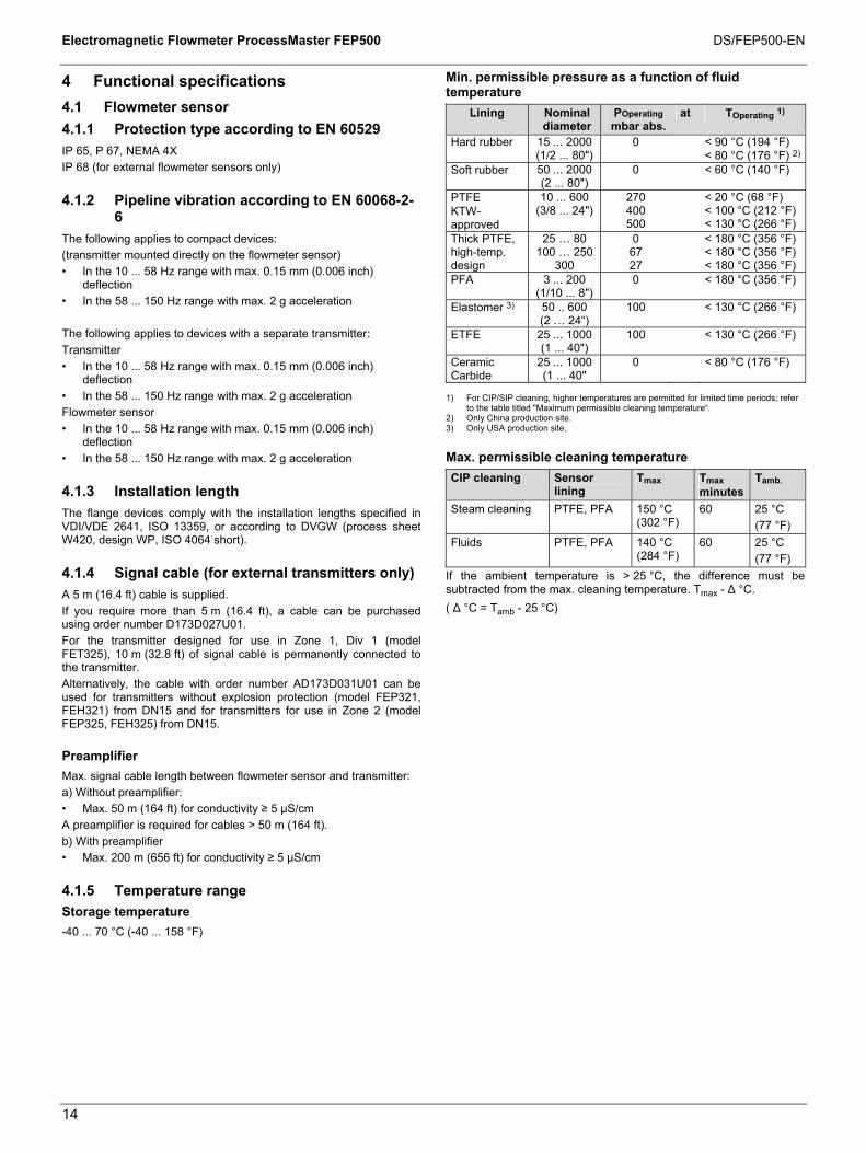
Min. permissible pressure as a function of fluid temperature
Lining Nominal diameter
POperating mbar abs.
at TOperating 1)
Hard rubber 15 ... 2000 (1/2 ... 80")
0 < 90 °C (194 °F) < 80 °C (176 °F) 2)
Soft rubber 50 ... 2000 (2 ... 80")
0 < 60 °C (140 °F)
PTFE KTW-approved
10 ... 600 (3/8 ... 24")
270 400 500
< 20 °C (68 °F) < 100 °C (212 °F) < 130 °C (266 °F)
Thick PTFE, high-temp. design
25 … 80 100 … 250
300
0 67 27
< 180 °C (356 °F) < 180 °C (356 °F) < 180 °C (356 °F)
PFA 3 ... 200 (1/10 ... 8")
0 < 180 °C (356 °F)
Elastomer 3) 50 .. 600 (2 … 24“)
100 < 130 °C (266 °F)
ETFE 25 ... 1000 (1 ... 40")
100 < 130 °C (266 °F)
Ceramic Carbide
25 ... 1000 (1 ... 40"
0 < 80 °C (176 °F)
1) For CIP/SIP cleaning, higher temperatures are permitted for limited time periods; refer
to the table titled "Maximum permissible cleaning temperature“. 2) Only China production site. 3) Only USA production site. Max. permissible cleaning temperature CIP cleaning Sensor
lining Tmax Tmax
minutesTamb.
Steam cleaning PTFE, PFA 150 °C (302 °F)
60 25 °C (77 °F)
Fluids PTFE, PFA 140 °C (284 °F)
60 25 °C (77 °F)
If the ambient temperature is > 25 °C, the difference must be subtracted from the max. cleaning temperature. Tmax - Δ °C. ( Δ °C = Tamb - 25 °C)
Change from one to two columns
Electromagnetic Flowmeter ProcessMaster FEP500 DS/FEP500-EN
15
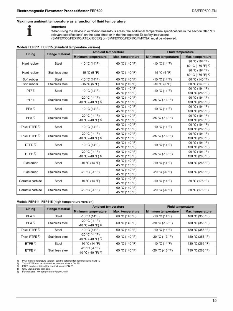
Maximum ambient temperature as a function of fluid temperature
Important When using the device in explosion hazardous areas, the additional temperature specifications in the section titled "Ex relevant specifications" on the data sheet or in the the separate Ex safety instructions (SM/FEX300/FEX500/ATEX/IECEX) or (SM/FEX300/FEX500/FM/CSA) must be observed.
Models FEP511, FEP515 (standard temperature version)
Ambient temperature Fluid temperature Lining Flange material Minimum temperature Max. temperature Minimum temperature Max. temperature
Hard rubber Steel -10 °C (14°F) 60 °C (140 °F) -10 °C (14°F) 90 °C (194 °F)
80 °C (176 °F) 4)
Hard rubber Stainless steel -15 °C (5 °F) 60 °C (140 °F) -15 °C (5 °F) 90 °C (194 °F)
80 °C (176 °F) 4) Soft rubber Steel -10 °C (14°F) 60 °C (140 °F) -10 °C (14°F) 60 °C (140 °F) Soft rubber Stainless steel -15 °C (5 °F) 60 °C (140 °F) -15 °C (5 °F) 60 °C (140 °F)
PTFE Steel -10 °C (14°F) 60 °C (140 °F) 45 °C (113 °F)
-10 °C (14°F) 90 °C (194 °F)
130 °C (266 °F)
PTFE Stainless steel -20 °C (-4 °F)
-40 °C (-40 °F) 5) 60 °C (140 °F) 45 °C (113 °F)
-25 °C (-13 °F) 90 °C (194 °F)
130 °C (266 °F)
PFA 1) Steel -10 °C (14°F) 60 °C (140 °F) 45 °C (113 °F)
-10 °C (14°F) 90 °C (194 °F)
130 °C (266 °F)
PFA 1) Stainless steel -20 °C (-4 °F)
-40 °C (-40 °F) 5) 60 °C (140 °F) 45 °C (113 °F)
-25 °C (-13 °F) 90 °C (194 °F)
130 °C (266 °F)
Thick PTFE 2) Steel -10 °C (14°F) 60 °C (140 °F) 45 °C (113 °F)
-10 °C (14°F) 90 °C (194 °F)
130 °C (266 °F)
Thick PTFE 2) Stainless steel -20 °C (-4 °F)
-40 °C (-40 °F) 5) 60 °C (140 °F) 45 °C (113 °F)
-25 °C (-13 °F) 90 °C (194 °F)
130 °C (266 °F)
ETFE 3) Steel -10 °C (14°F) 60 °C (140 °F) 45 °C (113 °F)
-10 °C (14°F) 90 °C (194 °F)
130 °C (266 °F)
ETFE 3) Stainless steel -20 °C (-4 °F)
-40 °C (-40 °F) 5) 60 °C (140 °F) 45 °C (113 °F)
-25 °C (-13 °F) 90 °C (194 °F)
130 °C (266 °F)
Elastomer Steel -10 °C (14 °F) 60 °C (140 °F) 45 °C (113 °F)
-10 °C (14°F) 130 °C (266 °F)
Elastomer Stainless steel -20 °C (-4 °F) 60 °C (140 °F) 45 °C (113 °F)
-20 °C (-4 °F) 130 °C (266 °F)
Ceramic carbide Steel -10 °C (14 °F) 60 °C (140 °F) 45 °C (113 °F)
-10 °C (14°F) 80 °C (176 °F)
Ceramic carbide Stainless steel -20 °C (-4 °F) 60 °C (140 °F) 45 °C (113 °F)
-20 °C (-4 °F) 80 °C (176 °F)
Models FEP511, FEP515 (high-temperature version) Ambient temperature Fluid temperature
Lining Flange material Minimum temperature Max. temperature Minimum temperature Max. temperature
PFA 1) Steel -10 °C (14°F) 60 °C (140 °F) -10 °C (14°F) 180 °C (356 °F)
PFA 1) Stainless steel -20 °C (-4 °F)
-40 °C (-40 °F) 5) 60 °C (140 °F) -20 °C (-13 °F) 180 °C (356 °F)
Thick PTFE 2) Steel -10 °C (14°F) 60 °C (140 °F) -10 °C (14°F) 180 °C (356 °F)
Thick PTFE 2) Stainless steel -20 °C (-4 °F)
-40 °C (-40 °F) 5) 60 °C (140 °F) -20 °C (-13 °F) 180 °C (356 °F)
ETFE 3) Steel -10 °C (14 °F) 60 °C (140 °F) -10 °C (14°F) 130 °C (266 °F)
ETFE 3) Stainless steel -20 °C (-4 °F)
-40 °C (-40 °F) 5) 60 °C (140 °F) -20 °C (-13 °F) 130 °C (266 °F)
1) PFA (high-temperature version) can be obtained for nominal sizes ≥ DN 10 2) Thick PTFE can be obtained for nominal sizes ≥ DN 25 3) ETFE can be obtained for nominal sizes ≥ DN 25 4) Only China production site 5) For (optional) low-temperature version, only

Electromagnetic Flowmeter ProcessMaster FEP500 DS/FEP500-EN
16
Important When using the device in explosion hazardous areas, the additional temperature specifications in the section titled "Ex relevant specifications" on the data sheet or in the the separate Ex safety instructions (SM/FEX300/FEX500/ATEX/IECEX) or (SM/FEX300/FEX500/FM/CSA) must be observed.
Models FEP521, FEP525 (standard temperature version)
Ambient temperature Fluid temperature Lining Flange material
Minimum temperature Max. temperature Minimum temperature Max. temperature
Hard rubber Steel -10 °C (14°F) 60 °C (140 °F) -10 °C (14°F) 90 °C (194 °F)
80 °C (176 °F) 4)
Hard rubber Stainless steel -15 °C (5 °F) 60 °C (140 °F) -15 °C (5 °F) 90 °C (194 °F)
80 °C (176 °F) 4)
Soft rubber Steel -10 °C (14°F) 60 °C (140 °F) -10 °C (14°F) 60 °C (140 °F)
Soft rubber Stainless steel -15 °C (5 °F) 60 °C (140 °F) -15 °C (5 °F) 60 °C (140 °F)
PTFE Steel -10 °C (14°F) 60 °C (140 °F) -10 °C (14°F) 130 °C (266 °F)
PTFE Stainless steel -25 °C (-13 °F)
-40 °C (-40 °F) 5) 60 °C (140 °F) -25 °C (-13 °F) 130 °C (266 °F)
PFA 1) Steel -10 °C (14°F) 60 °C (140 °F) -10 °C (14°F) 130 °C (266 °F)
PFA 1) Stainless steel -25 °C (-13 °F)
-40 °C (-40 °F) 5) 60 °C (140 °F) -25 °C (-13 °F) 130 °C (266 °F)
Thick PTFE 2) Steel -10 °C (14°F) 60 °C (140 °F) -10 °C (14°F) 130 °C (266 °F)
Thick PTFE 2) Stainless steel -25 °C (-13 °F)
-40 °C (-40 °F) 5) 60 °C (140 °F) -25 °C (-13 °F) 130 °C (266 °F)
ETFE 3) Steel -10 °C (14°F) 60 °C (140 °F) -10 °C (14°F) 130 °C (266 °F)
ETFE 3) Stainless steel -25 °C (-13 °F) 60 °C (140 °F) -25 °C (-13 °F) 130 °C (266 °F) Elastomer Steel -10 °C (14 °F) 60 °C (140 °F) -10 °C (14°F) 130 °C (266 °F) Elastomer Stainless steel -20 °C (-4 °F) 60 °C (140 °F) -20 °C (-4 °F) 130 °C (266 °F)
Ceramic carbide Steel -10 °C (14 °F) 60 °C (140 °F) -10 °C (14°F) 80 °C (176 °F) Ceramic carbide Stainless steel -25 °C (-13 °F) 60 °C (140 °F) -20 °C (-4 °F) 80 °C (176 °F)
Models FEP521, FEP525 (high-temperature version)
Ambient temperature Fluid temperature Lining Flange material
Minimum temperature Max. temperature Minimum temperature Max. temperature
PFA 1) Steel -10 °C (14°F) 60 °C (140 °F) -10 °C (14°F) 180 °C (356 °F)
PFA 1) Stainless steel -25 °C (-13 °F)
-40 °C (-40 °F) 5) 60 °C (140 °F) -25 °C (-13 °F) 180 °C (356 °F)
Thick PTFE 2) Steel -10 °C (14°F) 60 °C (140 °F) -10 °C (14°F) 180 °C (356 °F)
Thick PTFE 2) Stainless steel -25 °C (-13 °F)
-40 °C (-40 °F) 5) 60 °C (140 °F) -25 °C (-13 °F) 180 °C (356 °F)
ETFE 3) Steel -10 °C (14°F) 60 °C (140 °F) -10 °C (14°F) 130 °C (266 °F)
ETFE 3) Stainless steel -25 °C (-13 °F)
-40 °C (-40 °F) 5) 60 °C (140 °F) -25 °C (-13 °F) 130 °C (266 °F)
1) PFA (high-temperature version) can be obtained for nominal sizes ≥ DN 10 2) Thick PTFE can be obtained for nominal sizes ≥ DN 25 3) ETFE can be obtained for nominal sizes ≥ DN 25 4) Only China production site 5) For (optional) low-temperature version, only

Electromagnetic Flowmeter ProcessMaster FEP500 DS/FEP500-EN
17
Change from one to two columns
4.1.6 Material load
Limits for the permissible fluid temperature (TS) and permissible pressure (PS) are calculated on the basis of the lining and flange material used in the device (refer to the name plate on the device).
DIN flange stainless steel to DN 600 (24“)
G00589TS
PN 40
PN 25
PN 16
PN 10
PN 63
PN 100
-30-22
-1014
1050
3086
50122
70158
90194
110230
130266
150302
170 [°C]338 [°F]
0
10
20
30
40
50
60
70
80
90
100
PS[bar]110
145.0
290.1
435.1
580.2
725.2
870.2
1015.3
1160.3
1305.3
1450.4
PS[PSI]
1595.4
Fig. 3
ASME flange, stainless steel, up to DN 400 (16”) (CL150/300) up to DN 1000 (40”) (CL150)
G00591
CL300
CL150
CL600
-30-22
-1014
1050
3086
50122
70158
90194
110230
130266
150302
170 [°C]338 [°F]
0
10
20
30
40
50
60
70
80
90
100
PS[bar]110
TS
145.0
290.1
435.1
580.2
725.2
870.2
1015.3
1160.3
1305.3
1450.4
PS[PSI]
1595.4
Fig. 4
DIN flange, steel, up to DN 600 (24")
G00588
0
10
20
30
40
50
60
70
80
90
100
PS[bar]110
-30-22
-1014
1050
30122
50122
70158
90194
110230
130266
150302
170 [°C]338 [°F]
TS
PN 40
PN 25
PN 16
PN 10
PN 63
PN 100
145.0
290.1
435.1
580.2
725.2
870.2
1015.3
1160.3
1305.3
1450.4
PS[PSI]
1595.4
Fig. 5
ASME flange, steel, up to DN 400 (16") (CL150/300); up to DN 1000 (40") (CL150)
Fig. 6
JIS 10K-B2210 flange Nominal diameter
Material PN TS PS
32 ... 100 (1 1/4 ... 4")
Stainless steel 10 -25 ... 180 °C (-13 ... 356 °F)
10 bar (145 psi)
32 ... 100 (1 1/4 ... 4")
Steel 10 -25 ... 180 °C (14 ... 356 °F)
10 bar (145 psi)
DIN flange, stainless steel, DN 700 (28") up to DN 1000 (40")
G00219
PS[bar]
TS
6
7
8
9
10
11
12
13
14
15
16
17
DN 700 PN 16
DN 900 PN 16DN 800 PN 16
DN 1000 PN 16
DN 900 PN10DN 800 PN 10DN 700 PN 10
DN 1000 PN 10
-30 -20 -10 0 10 20 30 40 50 60 70 80 90 [°C]
-22 -4 14 32 50 68 86 104 122 140 158 176 194 [°F]
PS[psi]
87.0
101.5
116.0
130.5
145.0
159.5
174.0
188.5
203.0
217.5
232.0
246.5
Fig. 7
DIN flange, steel, DN 700 (28") up to DN 1000 (40")
G00220
PS[bar]
TS
DN 700 PN 16
DN 900 PN 16DN 800 PN 16
DN 1000 PN 16
DN 900 PN 10DN 800 PN 10DN 700 PN 10
DN 1000 PN 106
7
8
9
10
11
12
13
14
15
16
17
-10 0 10 20 30 40 50 60 70 80 90 [°C]
-14 32 50 68 86 104 122 140 158 176 194 [°F]
PS[psi]
87.0
101.5
116.0
130.5
145.0
159.5
174.0
188.5
203.0
217.5
232.0
246.5
Fig. 8

Electromagnetic Flowmeter ProcessMaster FEP500 DS/FEP500-EN
18
4.1.7 Flowmeter sensor
Parts that come into contact with fluid Part Standard Option Lining PTFE, PFA, ETFE,
hard rubber, soft rubber
Ceramic Carbide, Elastomer
Measurement and grounding electrode for:
- Hard rubber
- Soft rubber
CrNi steel 1.4571 (AISI 316Ti)
Hastelloy B-3 (2.4600), Hastelloy C-4 (2.4610), titanium, tantalum, platinum-iridium, 1.4539 (AISI 904L)
- PTFE, PFA, ETFE
CrNi steel 1.4539 (AISI 904L)
CrNi steel 1.4571 (AISI 316Ti) Hast. C-4 (2.4610) Hast. B-3 (2.4600) Titanium, tantalum, platinum-iridium
Grounding plate Stainless steel On request Protection plate Stainless steel On request
Parts that do not come into contact with fluid (process connection) Standard Option DN 3 ... 15 (1/10 ... 1/2")
Stainless steel 1) -
DN 20 ... 400 (3/4 ... 16")
Steel (galvanized) 2)
Stainless steel 1)
DN 450 ... 2000 (18 ... 80")
Steel (painted) 2) -
The process connections are made of one of the materials listed below: 1) 1.4301 (AISI 304), 1.4307, 1.4404 (AISI 316L) 1.4435 (AISI 316L), 1.4541 (AISI 321)
1.4571 (AISI 316Ti), ASTM A182 F304, ASTM A182 F304L, ASTM A182 F316L, ASTM A182 F321, ASTM A182 F316TI, ASTM A182 F316, 0Cr18Ni9, 0Cr18Ni10, 0Cr17Ni13Mo2, 0Cr27Ni12Mo3, 1Cr18Ni9Ti, 0Cr18Ni12Mo2Ti
2) 1.0038, 1.0460, 1.0570, 1.0432, ASTM A105, Q255A, 20#, 16Mn
Flowmeter sensor housing Standard Housing
DN 3 ... 400 (1/10 ... 16")
Dual-shell casing, cast aluminum, painted, paint coat, ≥ 80 µm thick, RAL 9002
DN 450 ... 2000 (18 ... 80")
Welded steel design, painted, paint coat, ≥ 80 µm thick, RAL 9002
Terminal box Aluminum alloy, painted, ≥ 80 µm thick, light gray, RAL 9002
Meter tube Stainless steel cable gland used Polyamide, stainless steel (version for
ambient temperature -40 °C (40 °F))

Electromagnetic Flowmeter ProcessMaster FEP500 DS/FEP500-EN
19
Change from one to two columns
4.2 Electrical connection
4.2.1 Models FEP511, FEP521, FET521 with HART protocol
G00474-FEP
31 32
A24 V
51 52 81 82 41 42L N
1+ 2-
M1 M2 D1 D2 3 2S E2 E1 1S
M1 M2 D1 D2 3 2S E2 E1 1S SEB
2 3 4 51 PE
7 8 9 10 11 12 13
6
6
< 50 m (200 m)< 164 ft (656 ft)
SE+ - + - + - + -
Fig. 9
A Transmitter B Flowmeter sensor 1 Supply power
See name plate 2 Current output (terminals 31/32)
The current output can be operated in "active" or "passive" mode. • Active: 4 ... 20 mA, HART protocol (standard), load: 250 Ω ≤ R ≤ 650 Ω • Passive: 4 ... 20 mA, HART protocol (standard), load: 250 Ω ≤ R ≤ 650 Ω Supply voltage for the current output: minimum 11 V, maximum 30 V at terminals 31/32.
3 Digital output DO1 (terminals 51/52) (pulse output or digital output) Function can be configured locally as "Pulse Output" or "Digital Output" using software. Factory setting is "Pulse Output". The output can be configured as an "active" or "passive" output. Configuration is performed using software. • Configuration as pulse output. Max. pulse frequency: 5250 Hz. Pulse width: 0.1 … 2,000 ms. The pulse factor and pulse width are interdependent and are calculated dynamically. • Configuration as contact output Function: System alarm, empty pipe alarm, max./min. alarm, flow direction signaling, other • Configuration as "active" output U = 19 ... 21 V, Imax = 220 mA , fmax ≤ 5,250 Hz • Configuration as "passive" output Umax = 30 V, Imax = 220 mA, fmax ≤ 5250 Hz
4 Digital input (terminals 81/82) (contact input) Function can be configured locally using software: External output switch-off, external totalizer reset, external totalizer stop, other Data for the optocoupler: 16 V ≤ U ≤ 30 V, Ri = 2 kΩ
5 Digital output DO2 (terminals 41/42) (pulse output or digital output) Function can be configured locally as "Pulse Output" or "Digital Output" using software. Factory setting is "Digital Output", flow direction signaling. The output is always a "passive" output (optocoupler). Data for the optocoupler: Umax = 30 V, Imax = 220 mA, fmax ≤ 5250 Hz
6 Functional ground 7 Brown 8 Red 9 Orange 10 Yellow 11 Green 12 Blue 13 Violet

Electromagnetic Flowmeter ProcessMaster FEP500 DS/FEP500-EN
20
4.2.2 Models FEP511, FEP521, FET521 with PROFIBUS PA, FOUNDATION Fieldbus
G01002-FEP
97 98
A
41 42L N
1+ 2-
M1 M2 D1 D2 3 2S E2 E1 1S
M1 M2 D1 D2 3 2S E2 E1 1S SEB
2 3 4 51 PE
7 8 9 10 11 12 13
6
PA+ PA-
FF+ FF-
6
< 50 m (200 m)< 164 ft (656 ft)
SE+ -
Fig. 10
A Transmitter B Flowmeter sensor 1 Supply power
See name plate 2 Digital communication (terminal 97 / 98)
• PROFIBUS PA in acc. with IEC 61158-2 (PA+ / PA-) U = 9 ... 32 v, I = 10 mA (normal operation), I = 13 mA (in the event of an error / FDE) Bus connection with integrated protection against polarity reversal The bus address can be set via the DIP switches in the device, the transmitter display or the fieldbus.
or • FOUNDATION Fieldbus in acc. with IEC 61158-2 (FF+ / FF-)
U = 9 ... 32 v, I = 10 mA (normal operation), I = 13 mA (in the event of an error / FDE) Bus connection with integrated protection against polarity reversal
3 Not assigned 4 Not assigned 5 Digital output DO2 (terminals 41/42) (pulse output or digital output)
Function can be configured locally as "Pulse Output" or "Digital Output" using software. Factory setting is "Digital Output", flow direction signaling. The output is always a "passive" output (optocoupler). Data for the optocoupler: Umax = 30 V, Imax = 220 mA, fmax ≤ 5250 Hz
6 Functional ground 7 Brown 8 Red 9 Orange 10 Yellow 11 Green 12 Blue 13 Violet

Electromagnetic Flowmeter ProcessMaster FEP500 DS/FEP500-EN
21
4.2.3 Connection examples for the peripherals
Current output Max. permissible load (RB) as a function of the source voltage (U2) A = "Active" configuration:
4 ... 20 mA, HART Load: 0 =R = 650 Ω (300 Ω for Ex zone 1 / Div. 1) Min. load with HART: 250 Ω
G00475
+31
-32
I E
+31
-32
I E
V
A
B
RB
RB
U1 U2
B = "Passive" configuration: 4 ... 20 mA, HART Load: 0 =R = 650 Ω Min. load with HART: 250 Ω Supply voltage for the current output, terminals 31/32: U1: Min. 11 V, max. 30 V
I = internal, E = external G00592
200
250
300
350
400
450
500
550
600
650
700
17 18 19 20 21 22 23 24 25 26 27 28 29 30U [V]2
R[
]B
Ω
Fig. 11 Digital output DO1
Max. permissible load (RB) as a function of the source voltage (U2)
A = "Active" configuration 24V+
-
I E
51
52
RB*
Imax = 220 mA
24V+
-
RB* U
CE
ICE
I E
51
52
G00476-02
A
B
U2
B = "Passive" configuration
G00593
50
150
250
350
450
550
650
750
850
950
1050
1150
1250
1350
1450
1550
16 17 18 19 20 21 22 23 24 25 26 27 28 29 30U [V]2
R[
]B
Ω
I = internal, E = external = Permissible range Fig. 12 Digital output DO2, e.g., for system monitoring, max./min. alarm, empty meter tube or forward/reverse signal, or counting pulses (function can be configured using software)
G00792
RB*
Imax = 220 mA
RB* U
CE
ICE
+U
I E
41
42
I = internal, E = external
Fig. 13

Electromagnetic Flowmeter ProcessMaster FEP500 DS/FEP500-EN
22
Digital outputs DO1 and DO2, separate forward and reverse pulses
Digital outputs DO1 and DO2, separate forward and reverse pulses (alternative connection)
G00791
24V+
I E
51
52
41
4224V
I E
51
52
41
42
V +-
I = internal, E = external
Fig. 14 Digital input for external output switch-off or external totalizer reset
I = internal, E = external
Fig. 15 PROFIBUS PA and FOUNDATION Fieldbus
G002482
FF-
FF+R
C
1
97
PA-
R
CPA+
98
97
98
I EI E
The resistance R and condenser C form the bus termination. They must be installed when the device is connected to the end of the entire bus cable. R = 100 Ω; C = 1 µF 1 PROFIBUS PA 2 FOUNDATION Fieldbus
I = internal, E = external Fig. 16 Connection via M12 plug (only for PROFIBUS PA in non-hazardous areas)
G01003
1 2
34
Pin assignment (Front view showing pin insert and pins) PIN 1 = PA+ PIN 2 = nc PIN 3 = PA- PIN 4 = shield
Fig. 17

Electromagnetic Flowmeter ProcessMaster FEP500 DS/FEP500-EN
23
Change from one to two columns
Digital communication The transmitter has the following options for digital communication: HART protocol The unit is registered with the HART Communication Foundation.
Fig. 18
HART protocol Configuration Directly on the device
Software DAT200 Asset Vision Basic (+ HART-DTM)
Transmission FSK modulation on current output 4 ... 20 mA acc. to Bell 202 standard
Max. signal amplitude
1.2 mAss
Current output load
Min. 250 Ω, max. = 560 Ω
Cable AWG 24 twisted Max. cable length 1500 m Baud rate 1,200 baud Display Log. 1: 1,200 Hz
Log. 0: 2200 Hz For additional information, see the separate interface description. System integration In conjunction with the DTM (Device Type Manager) available for the device, communication (configuration, parameterization) can occur with the corresponding framework applications according to FDT 1.21 (DAT200 Asset Vision Basic). Other tool/system integrations (e.g., Emerson AMS/Siemens PCS7) are available upon request. A free of charge version of the DAT200 Asset Vision Basic framework application for HART® or PROFIBUS is available upon request. The required DTMs are contained on the DAT200 Asset Vision Basic DVD or in the DTM Library. They can also be downloaded from www.abb.com/flow.
PROFIBUS PA protocol The interface conforms to profile 3.01 (PROFIBUS standard, EN 50170, DIN 19245 [PRO91]).
PROFIBUS PA ID no.: 0x3430 Alternative standard ID no.: 0x9700 or 0x9740 Configuration Directly on the device
Software DAT200 Asset Vision Basic (+ PROFIBUS PA-DTM)
Transmission signal Acc. to IEC 61158-2 Cable Shielded, twisted cable (acc. to
IEC 61158-2, types A or B are preferred)
1 F
100
G00111
A
PROFIBUS DP PROFIBUS PA
H2-Bus
PA+ PA- PA+ PA- PA+ PA-
A = Segment coupler (incl. bus supply and termination)
Fig. 19: Example for PROFIBUS PA interface connection Bus topology • Tree and/or line structure • Bus termination: passive at both ends of the main bus line (RC
element R = 100 Ω, C = 1 µF) Voltage / current consumption • Average current consumption: 10 mA • In the event of an error, the integrated FDE function (=Fault
Disconnection Electronic) integrated in the device is ensures that the current consumption can rise to a maximum of 13 mA.
• The upper current limit is restricted electronically. • The voltage on the bus line must lie in the range of 9 ... 32 V DC. For additional information, see the separate interface description. System integration ABB provides three different GSD files (equipment master data) which can be integrated in the system. Users decide at system integration whether to install the full range of functions or only part. The change-over is done using the “ID-number selector” parameter. ID number 0x9700, GSD file name: PA139700.gsd ID number 0x9740, GSD file name: PA139740.gsd ID number 0x3430, GSD file name: ABB_3430.gsd The interface description appears on the CD included in the scope of supply. The GSD files can also be downloaded from www.abb.com/flow. The files required for operation can be downloaded from www.profibus.com.

Electromagnetic Flowmeter ProcessMaster FEP500 DS/FEP500-EN
24
FOUNDATION Fieldbus (FF) Interoperability test campaign no.
ITK 5.20
Manufacturer ID 0x000320 Device ID 0x0124 Configuration • Directly on the device
• Via services integrated in the system
• National configurator Transmission signal Acc. to IEC 61158-2
B
Ethernet FOUNDATION Fieldbus H1
HSE-Bus
FF+ FF- FF+ FF- FF+ FF-
1 F
100
G00112 B = Linking device (incl. bus supply and termination)
Fig. 20: Example for FOUNDATION Fieldbus interface connection Bus topology • Tree and/or line structure • Bus termination: passive at both ends of the main bus line (RC
element R = 100 Ω, C = 1 µF) Voltage / current consumption • Average current consumption: 10 mA • In the event of an error, the integrated FDE function (=Fault
Disconnection Electronic) integrated in the device is ensures that the current consumption can rise to a maximum of 13 mA.
• Upper current limit: electronically restricted. • The voltage on the bus line must lie in the range of 9 ... 32 V DC.
Bus address The bus address is automatically assigned or can be set in the system manually. The identifier (ID) is formed using a unique combination of manufacturer ID, device ID, and device serial number. System integration The following are required: • DD (Device Description) file, which includes the device
description. • The CFF (Common File Format) file is required for engineering
the segment. Engineering can be performed online or offline. The interface description appears on the CD included in the scope of supply. The files can also be downloaded from www.abb.com/flow. The files required for operation can also be downloaded from http://www.fieldbus.org.
Change from one to two columns

Electromagnetic Flowmeter ProcessMaster FEP500 DS/FEP500-EN
25
5 Ex-relevant specifications for operation in zones 1, 21, 22 / Div. 1 A
5.1 General
Devices with model names FEP515 and FEP525 are approved for operation in the following potentially explosive areas: • ATEX/IECEx Zone 1, 21, 22 • FM Div.1 • cFM Div.1
Important For detailed information on the individual approvals, refer to Section 1, "ProcessMaster 500 - Overview of technology".
Important The housing for the transmitter and flowmeter sensor must be connected to the potential equalization PA. The operator must ensure that when connecting the protective conductor (PE) no potential differences can occur between protective conductor and potential equalization (PA).
A temperature of 70 °C (158 °F) at the cable entry is assumed for the Ex calculations. Therefore, the cables used for the supply power and the signal inputs and outputs must have a minimum specification of 70 °C (158 °F).
For devices with remote mount design for use in FM / cFM Div. 1 or FM / cFM Div. 2 the signal cable between the flowmeter sensor and the transmitter must have a minimum length of 5 m (16.4 ft).

Electromagnetic Flowmeter ProcessMaster FEP500 DS/FEP500-EN
26
5.2 Electrical connection
5.2.1 Models FEP515, FEP525 and FET525 in Zone 1 / Div. 1 with HART protocol
G01011
31 32
A24 V
51 52 81 82 41 42L N
1+ 2-
M1 M2 D1 D2 3 2S E2 E1 1S
M1 M2 D1 D2 3 E2 E1 SEB
2 3 4 51 PE
7 8 9 10 11 12 13
6
SE+ - + - + - + -
FEP515
FEP525 FET525
6
6
6
6
Fig. 21
A Transmitter B Flowmeter sensor 1 Supply power: See name plate 2 Current output (terminals 31/32) Dependent upon the device design, an "active" or a "passive"
output will be available. For devices designed for use in Ex Zone 1, the current output
cannot be reconfigured locally. • Active: 4 ... 20 mA, HART protocol (standard), load: 250 Ω ≤ R ≤
300 Ω • Passive: 4 ... 20 mA, HART protocol (standard),
load: 250 Ω ≤ R ≤ 650 Ω, Supply voltage for the current output: minimum 11 V, maximum 30 V at terminals 31/32.
3 Digital output DO1 (terminal 51/52) The output is always a "passive" output (optocoupler).
• Data for the optocoupler: Umax = 30 V, Imax = 220 mA, Function can be configured locally as "Pulse Output" or "Digital
Output" using software. Factory setting is "Pulse Output". • Configuration as pulse output. Maximum pulse frequency:
5,250 Hz, pulse width: 0.1 … 2,000 ms. The pulse factor and pulse width are interdependent and are calculated dynamically.
• Configuration as contact output. Function: System alarm, empty pipe alarm, max./min. alarm, flow direction signaling, other
4 Digital input: (terminal 81/82) Only available in conjunction with "passive" current output. Function can be configured locally using software: External output
switch-off, external totalizer reset, external totalizer stop, other Data for the optocoupler: 16 V ≤ U ≤ 30 V, Ri = 2 kΩ 5 Digital output DO2 (terminal 41/42) The output is always a "passive" output (optocoupler). Data for the optocoupler: Umax = 30 V, Imax = 220 mA Function can be configured locally as "Pulse Output" or "Digital
Output" using software. Factory setting is "Digital Output", flow direction signaling.
6 Equipotential bonding 7 Brown 8 Red 9 Orange 10 Yellow 11 Green 12 Blue 13 Violet
All inputs and outputs are electrically isolated from each other and from the supply power. The electrical specifications given are operating values.
Electromagnetic Flowmeter ProcessMaster FEP500 DS/FEP500-EN
27
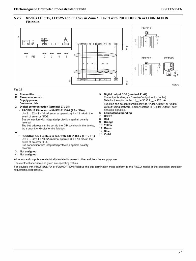
5.2.2 Models FEP515, FEP525 and FET525 in Zone 1 / Div. 1 with PROFIBUS PA or FOUNDATION Fieldbus
G01012
97 98
A
41 42L N
1+ 2-
M1 M2 D1 D2 3 2S E2 E1 1S
M1 M2 D1 D2 3 E2 E1 SEB
2 3 4 51 PE
7 8 9 10 11 12 13
6
SE+ -
FEP515
FEP525 FET525
6
6
6
6
PA+ PA-
FF+ FF-
Fig. 22
A Transmitter B Flowmeter sensor 1 Supply power: See name plate 2 Digital communication (terminal 97 / 98)
• PROFIBUS PA in acc. with IEC 61158-2 (PA+ / PA-) U = 9 ... 32 v, I = 10 mA (normal operation), I = 13 mA (in the event of an error / FDE) Bus connection with integrated protection against polarity reversal The bus address can be set via the DIP switches in the device, the transmitter display or the fieldbus.
or • FOUNDATION Fieldbus in acc. with IEC 61158-2 (FF+ / FF-)
U = 9 ... 32 v, I = 10 mA (normal operation), I = 13 mA (in the event of an error / FDE) Bus connection with integrated protection against polarity reversal
3 Not assigned 4 Not assigned
5 Digital output DO2 (terminal 41/42) The output is always a "passive" output (optocoupler). Data for the optocoupler: Umax = 30 V, Imax = 220 mA Function can be configured locally as "Pulse Output" or "Digital
Output" using software. Factory setting is "Digital Output", flow direction signaling.
6 Equipotential bonding 7 Brown 8 Red 9 Orange 10 Yellow 11 Green 12 Blue 13 Violet
All inputs and outputs are electrically isolated from each other and from the supply power. The electrical specifications given are operating values. For devices with PROFIBUS PA or FOUNDATION Fieldbus the bus termination must conform to the FISCO model or the explosion protection regulations, respectively.

Electromagnetic Flowmeter ProcessMaster FEP500 DS/FEP500-EN
28
5.2.3 Model FEP525 in Zone 1 / Div. 1 and FET525 transmitter in Zone 2 / Div. 2 or FET521 outside the hazardous area with HART protocol
FEP525 flowmeter sensor in the hazardous area (Zone 1 / Div. 1)
FET525 transmitter in the hazardous area (Zone 2 / Div.
2)
FET521 transmitter outside the hazardous area
G00867
31 32
A24 V
51 52 81 82 41 42L N
1+ 2-
M1 M2 D1 D2 3 2S E2 E1 1S
M1 M2 D1 D2 3 E2 E1 SEB
2 3 4 51 PE
7 8 9 10 11 12 13
6 / 6a
SE+ - + - + - + -
6
6
6
6
6a
Fig. 23
A Transmitter B Flowmeter sensor 1 Supply power:
See name plate 2 Current output (terminals 31/32) The current output can be configured locally as an "active" or
"passive" output. • Active: 4 ... 20 mA, HART protocol (standard),
load: 250 Ω ≤ R ≤ 650 Ω • Passive: 4 ... 20 mA, HART protocol (standard),
load: 250 Ω ≤ R ≤ 650 Ω, Supply voltage for the current output: minimum 11 V, maximum 30 V at terminals 31/32.
3 Digital output DO1 (terminal 51/52) The digital output can be configured locally as an "active" or
"passive" output. • Active: U = 19 ... 21 V. Imax = 220 mA, fmax ≤ 5250 Hz • Passive: Umax = 30 V, Imax = 220 mA, fmax ≤ 5250 Hz
Function can be configured locally as "Pulse Output" or "Digital Output" using software. Factory setting is "Pulse Output". • Configuration as pulse output. Maximum pulse frequency:
5,250 Hz, pulse width: 0.1 … 2,000 ms. The pulse factor and pulse width are interdependent and are calculated dynamically.
• Configuration as contact output. Function: System alarm, empty pipe alarm, max./min. alarm, flow direction signaling, other
4 Digital input: (terminal 81/82) Function can be configured locally using software: External output
switch-off, external totalizer reset, external totalizer stop, other Data for the optocoupler: 16 V ≤ U ≤ 30 V, Ri = 2 kΩ
5 Digital output DO2 (terminal 41/42) The output is always a "passive" output (optocoupler). Data for the optocoupler: Umax = 30 V, Imax = 220 mA,
fmax ≤ 5250 Hz, Function can be configured locally as "Pulse Output" or "Digital
Output" using software. Factory setting is "Digital Output", flow direction signaling.
6 Equipotential bonding 6a Functional ground (only with flowmeter sensor FET321 outside
the hazardous area) 7 Brown 8 red 9 Orange 10 yellow 11 Green 12 blue 13 Violet
All inputs and outputs are electrically isolated from each other and from the supply power. The electrical specifications given are operating values.

Electromagnetic Flowmeter ProcessMaster FEP500 DS/FEP500-EN
29
5.2.4 Model FEP525 in Zone 1 / Div. 1 and FET525 transmitter in Zone 2 / Div. 2 or FET521 outside the hazardous area with PROFIBUS PA or FOUNDATION Fieldbus
FEP525 flowmeter sensor in the hazardous area (Zone 1 / Div. 1)
FET525 transmitter in the hazardous area (Zone 2 / Div.
2)
FET521 transmitter outside the hazardous area
G01006
97 98
A
41 42L N
1+ 2-
M1 M2 D1 D2 3 2S E2 E1 1S
M1 M2 D1 D2 3 E2 E1 SEB
2 3 4 51 PE
7 8 9 10 11 12 13
6 / 6a
SE+ -
6
6
6
6
6a
PA+ PA-
FF+ FF-
Fig. 24
A Transmitter B Flowmeter sensor 1 Supply power: See name plate 2 Digital communication (terminal 97 / 98)
• PROFIBUS PA in acc. with IEC 61158-2 (PA+ / PA-) U = 9 ... 32 v, I = 10 mA (normal operation), I = 13 mA (in the event of an error / FDE) Bus connection with integrated protection against polarity reversal The bus address can be set via the DIP switches in the device, the transmitter display or the fieldbus.
or • FOUNDATION Fieldbus in acc. with IEC 61158-2 (FF+ / FF-)
U = 9 ... 32 v, I = 10 mA (normal operation), I = 13 mA (in the event of an error / FDE) Bus connection with integrated protection against polarity reversal
3 Not assigned 4 Not assigned
5 Digital output DO2 (terminal 41/42) The output is always a "passive" output (optocoupler). Data for the optocoupler: Umax = 30 V, Imax = 220 mA,
fmax ≤ 5250 Hz, Function can be configured locally as "Pulse Output" or "Digital
Output" using software. Factory setting is "Digital Output", flow direction signaling.
6 Equipotential bonding 6a Functional ground (only with flowmeter sensor FET321 outside
the hazardous area) 7 Brown 8 red 9 Orange 10 yellow 11 Green 12 blue 13 Violet
All inputs and outputs are electrically isolated from each other and from the supply power. The electrical specifications given are operating values. For devices with PROFIBUS PA or FOUNDATION Fieldbus in Zone 2 / Div 2 the bus termination must conform to the FNICO model or the explosion protection regulations, respectively.

Electromagnetic Flowmeter ProcessMaster FEP500 DS/FEP500-EN
30
5.3 Electrical data for operation in Zone 1 / Div. 1
5.3.1 Devices with HART protocol
When operating in potentially explosive areas, observe the following electrical data for the signal inputs and outputs of the transmitter. For the correct current output design (active/passive), see the marking contained in the device's terminal box.
Model: FEP515 or FET525
Operating values Ex data Explosion protection type Ex i, IS
Inputs and outputs
UN [V]
IN [mA]
UO [V]
IO [mA]
PO [mW]
CO [nF]
COPA [nF]
LO [mH]
20 100 500 210 195 6 UI [V]
II [mA]
PI [mW]
CI [nF]
CIPA [nF]
LI [mH]
Active current output Terminal 31/32 30 30
60 425 4) 2000 4) 8,4 24 0,065 UI [V]
II [mA]
PI [mW]
CI [nF]
CIPA [nF]
LI [nH]
Passive current output Terminal 31/32
30 30 60 500 4) 2000 4) 8,4 24 170 UI [V]
II [mA]
PI [mW]
CI [nF]
CIPA [nF]
LI [nH]
Passive digital output DO2 Terminal 41/42 30 220
60 4251) 4) 5002) 4)
2000 4) 3,6 3,6 170
Passive digital output DO1 Terminal 51/52
30 220 60 4251) 4) 5002) 4)
2000 4) 3,6 3,6 170
Passive digital input DI 3)
Terminal 81/82 30 10 60 500 4) 2000 4) 3,6 3,6 170
1) For "active" current output 2) For "passive" current output 3) Only available in conjunction with passive current output 4) Intrinsically safe single-channel or multi-channel barriers (supply isolators) with resistance characteristic must be used. All inputs and outputs are electrically isolated from each other and from the supply power. Special connection conditions: The output circuits are designed in such a way that they can be connected to both intrinsically-safe and non-intrinsically-safe circuits. It is not permitted to combine intrinsically safe and non-intrinsically safe circuits. On intrinsically safe circuits, equipotential bonding must be in place along the entire length of the cable used for the current outputs. The rated voltage of the non-intrinsically safe circuits is UM = 60 V. Provided that rated voltage UM = 60 V is not exceeded if connections are established to non-intrinsically safe external circuits, intrinsic safety is still guaranteed.

Electromagnetic Flowmeter ProcessMaster FEP500 DS/FEP500-EN
31
5.3.2 Devices with PROFIBUS PA or FOUNDATION Fieldbus
When operating in potentially explosive areas, observe the following electrical data for the signal inputs and outputs of the transmitter. For the correct design (PROFIBUS PA or FOUNDATION Fieldbus), see the marking contained in the device's terminal box.
Model: FEP515 or FET525
The fieldbus (terminal 97 / 98) and the digital output (terminal 41 / 42) can be connected in Zone 1 / Div. 1 in three different variants. Variant 1 Intrinsically safe fieldbus connection in acc. with FISCO, intrinsically safe connection of the digital output
Operating values Ex data Explosion protection type Ex i, IS and FISCO
Inputs and outputs
UN [V]
IN [mA]
Ui [V]
Ii [mA]
Pi [mW]
Ci [nF]
CiPA [nF]
Li [µH]
Passive digital output DO2 Terminal 41/42
30 220 60 200 1) 5000 1) 3,6 3,6 0,17
Fieldbus Terminal 97/98 32 30 17 380 5320 1 1 5
1) Intrinsically safe single-channel or multi-channel barriers (supply isolators) with resistance characteristic must be used. Variant 2 Intrinsically safe fieldbus connection (not in acc. with FISCO!), intrinsically safe connection of the digital output
Operating values Ex data Explosion protection type Ex i, IS
Inputs and outputs
UN [V]
IN [mA]
Ui [V]
Ii [mA]
Pi [mW]
Ci [nF]
CiPA [nF]
Li [µH]
Passive digital output DO2 Terminal 41/42
30 220 60 200 1) 5000 1) 3,6 3,6 0,17
Fieldbus Terminal 97/98 32 30 60 500 5000 1 1 5
1) Intrinsically safe single-channel or multi-channel barriers (supply isolators) with resistance characteristic must be used. Variant 3 Fieldbus connection in acc. with FNICO (Zone 2, Div. 2), connection of digital output (Zone 2, Div. 2)
Operating values Ex data Explosion protection type Ex n, NI and FNICO
Inputs and outputs
UN [V]
IN [mA]
Ui [V]
Ii [mA]
Pi [mW]
Ci [nF]
CiPA [nF]
Li [µH]
Passive digital output DO2 Terminal 41/42
30 220 - - - - - -
Fieldbus Terminal 97/98 32 30 60 500 1) 5000 1) 1 1 5
1) Single-channel or multi-channel barriers (supply isolators) with resistance characteristic must be used. All inputs and outputs are electrically isolated from each other and from the supply power. Special connection conditions: The output circuits are designed in such a way that they can be connected to both intrinsically-safe and non-intrinsically-safe circuits. It is not permitted to combine intrinsically safe and non-intrinsically safe circuits. On intrinsically safe circuits, equipotential bonding must be in place along the entire length of the cable used for the signal outputs. The rated voltage of the non-intrinsically safe circuits is UM = 60 V. Provided that rated voltage UM = 60 V is not exceeded if connections are established to non-intrinsically safe external circuits, intrinsic safety is still given.

Electromagnetic Flowmeter ProcessMaster FEP500 DS/FEP500-EN
32
5.4 Temperature values
Model name Surface temperature FEP515 70 °C (158 °F) FEP525 85 °C (185 °F) FET525 70 °C (158 °F)
The surface temperature depends on the fluid temperature. With increasing fluid temperature > 70 °C (158 °F) or > 85 °C (185 °F) the surface temperature also increases to the level of the fluid temperature.
Important The maximum permissible fluid temperature depends on the lining and flange material, and is limited by the operating values in Table 1 and the explosion protection specifications in Tables 2 ... n.
Table 1: Fluid temperature as a function of lining and flange material
Models FEP515/FEP525
Materials Fluid temperature (operating values) Lining Flange Minimum Maximum
Hard rubber Steel -10 °C (14 °F) 90 °C (194 °F)
80 °C (176 °F) 1)
Hard rubber Stainless steel -15 °C (5 °F) 90 °C (194 °F)
80 °C (176 °F) 1) Soft rubber Steel -10 °C (14 °F) 60 °C (140 °F) Soft rubber Stainless steel -15 °C (5 °F) 60 °C (140 °F)
PTFE Steel -10 °C (14 °F) 130 °C (266 °F) PTFE Stainless steel -25 °C (-13 °F) 130 °C (266 °F) PFA Steel -10 °C (14 °F) 180 °C (356 °F) PFA Stainless steel -25 °C (-13 °F) 180 °C (356 °F)
Thick PTFE Steel -10 °C (14 °F) 180 °C (356 °F) Thick PTFE Stainless steel -25 °C (-13 °F) 180 °C (356 °F)
ETFE Steel -10 °C (14 °F) 130 °C (266 °F) ETFE Stainless steel -25 °C (-13 °F) 130 °C (266 °F)
1) Only China production site (under preparation)

Electromagnetic Flowmeter ProcessMaster FEP500 DS/FEP500-EN
33
Table 2: Fluid temperature (Ex data) for ProcessMaster model FEP515
Ambient temperature
(- 40 °C)1) - 20 °C ... + 40 °C (- 40 °C)1) - 20 °C ... + 50 °C (- 40 °C)1) - 20 °C ... + 60 °C
Not thermally insulated
Thermally insulated
Not thermally insulated
Thermally insulated
Not thermally insulated
Thermally insulated
Nom
inal
dia
met
er
Des
ign
Tem
pera
ture
cla
ss
Gas Gas & dust Gas Gas &
dust Gas Gas & dust Gas Gas &
dust Gas Gas & dust Gas Gas &
dust
NT 130 °C 90 °C 30 °C 80 °C 40 °C HT
T1 180 °C 120 °C 20 °C 120 °C 20 °C
NT 130 °C 90 °C 30 °C 80 °C 40 °C HT
T2 180 °C 120 °C 20 °C 120 °C 20 °C
NT 130 °C 90 °C 30 °C 80 °C 40 °C HT
T3 180 °C 120 °C 20 °C 120 °C 20 °C
NT 120 °C 90 °C 30 °C 80 °C 40 °C HT
T4 120 °C 120 °C 20 °C 120 °C 20 °C
NT 85 °C 70 °C 30 °C 80 °C 40 °C HT
T5 85 °C 85 °C 20 °C 85 °C 20 °C
NT 70 °C 70 °C 30 °C 70 °C 40 °C
DN
3 ..
. DN
100
HT T6
70 °C 70 °C 20 °CC 70 °C 20 °C NT 130 °C 90 °C 30 °C 80 °C 40 °C HT
T1 180 °C 120 °C 20 °C 120 °C 20 °C
NT 130 °C 90 °C 30 °C 80 °C 40 °C HT
T2 180 °C 120 °C 20 °C 120 °C 20 °C
NT 130 °C 90 °C 30 °C 80 °C 40 °C HT
T3 180 °C 120 °C 20 °C 120 °C 20 °C
NT 125 °C 90 °C 30 °C 80 °C 40 °C HT
T4 125 °C 120 °C 20 °C 120 °C 20 °C
NT 90 °C 90 °C 30 °C 80 °C 40 °C HT
T5 90 °C 90 °C 20 °C 90 °C 20 °C
NT 75 °C 75 °C 30 °C 75 °C 40 °C
DN
125
... D
N 2
000
HT T6
75 °C 75 °C 20 °C 75 °C 20 °C 1) Low-temperature version (option) NT standard version, Tmedium maximum 130 °C (266 °F) HT high-temperature version, Tmedium maximum 180 °C (356 °F) Not thermally insulated: The flowmeter sensor is not surrounded by pipe insulation material. Thermally insulated: The flowmeter sensor is surrounded by pipe insulation material.
Important The standard version includes explosion protection for gases and dust. • If the installation location for the device is classified as a potentially explosive area for gases and dust, the
temperature data in the "Gas & dust" columns in the table must be taken into consideration. • If the installation location for the device is classified as a potentially explosive area for gases only, the temperature
data in the "Gas" columns in the table must be taken into consideration.

Electromagnetic Flowmeter ProcessMaster FEP500 DS/FEP500-EN
34
Table 3: Fluid temperature (Ex data) for ProcessMaster Model FEP525
Ambient temperature
(- 40 °C)1) - 20 °C ... + 40 °C (- 40 °C)1) - 20 °C ... + 50 °C (- 40 °C)1) - 20 °C ... + 60 °C
Not thermally insulated
Thermally insulated
Not thermally insulated
Thermally insulated
Not thermally insulated
Thermally insulated
Nom
inal
dia
met
er
Des
ign
Tem
pera
ture
cla
ss
Gas Gas & dust Gas Gas &
dust Gas Gas & dust Gas Gas &
dust Gas Gas & dust Gas Gas &
dust
NT 130 °C 110 °C 110 °C 110 °C 110 °C HT
T1 180 °C 160 °C 150 °C 160 °C 150 °C
NT 130 °C 110 °C 110 °C 110 °C 110 °C HT
T2 180 °C 160 °C 150 °C 160 °C 150 °C
NT 130 °C 110 °C 110 °C 110 °C 110 °C HT
T3 180 °C 160 °C 150 °C 160 °C 150 °C
NT 120 °C 110 °C 110 °C 110 °C 110 °C HT
T4 120 °C 120 °C 120 °C 120 °C 120 °C
NT 85 °C 85 °C 85 °C 85 °C 85 °C HT
T5 85 °C 85 °C 85 °C 85 °C 85 °C
NT 70 °C 70 °C 70 °C 70 °C 70 °C
DN
3 ..
. DN
100
HT T6
70 °C 70 °C 70 °C 70 °C 70 °C NT 130 °C 110 °C 110 °C 110 °C 110 °C HT
T1 180 °C 160 °C 150 °C 160 °C 150 °C
NT 130 °C 110 °C 110 °C 110 °C 110 °C HT
T2 180 °C 160 °C 150 °C 160 °C 150 °C
NT 130 °C 110 °C 110 °C 110 °C 110 °C HT
T3 180 °C 160 °C 150 °C 160 °C 150 °C
NT 125 °C 110 °C 110 °C 110 °C 110 °C HT
T4 125 °C 125 °C 125 °C 125 °C 125 °C
NT 90 °C 90 °C 90 °C 90 °C 90 °C HT
T5 90 °C 90 °C 90 °C 90 °C 90 °C
NT 75 °C 75 °C 75 °C 75 °C 75 °C
DN
125
... D
N 2
000
HT T6
75 °C 75 °C 75 °C 75 °C 75 °C 1) Low-temperature version (option) NT standard version, Tmedium maximum 130 °C (266 °F). HT high temperature version, Tmedium maximum 180 °C (356 °F). Not thermally insulated: The flowmeter sensor is not surrounded by pipe insulation material. Thermally insulated: The flowmeter sensor is surrounded by pipe insulation material.
Important The standard version includes explosion protection for gases and dust. • If the installation location for the device is classified as a potentially explosive area for gases and dust, the
temperature data in the "Gas & dust" columns in the table must be taken into consideration. • If the installation location for the device is classified as a potentially explosive area for gases only, the temperature
data in the "Gas" columns in the table must be taken into consideration.

Electromagnetic Flowmeter ProcessMaster FEP500 DS/FEP500-EN
35
5.5 Special features of version designed for operation in Ex zone 1 / Div. 1
5.5.1 Configuring the current output
For devices designed for use in Ex Zone 1 / Div.1, the current output cannot be reconfigured subsequently.
The configuration required for the current output (active/passive) must be specified when the order is placed.
For the correct current output design (active/passive), see the marking contained in the device's terminal box.
5.5.2 Configuration of the digital outputs
For version designed for operation in Ex zone 1 / Div. 1, the digital outputs DO1 (51/52) and DO2 (41/42) can be configured on a NAMUR switching amplifier. On leaving the factory, the device is configured with the standard wiring (non-NAMUR).
Devices with PROFIBUS PA or FOUNDATION Fieldbus only have the digital output DO2 (41 / 42).
Important The outputs' type of protection remains unaffected by this. The devices connected to these outputs must conform to the applicable regulations for explosion protection.
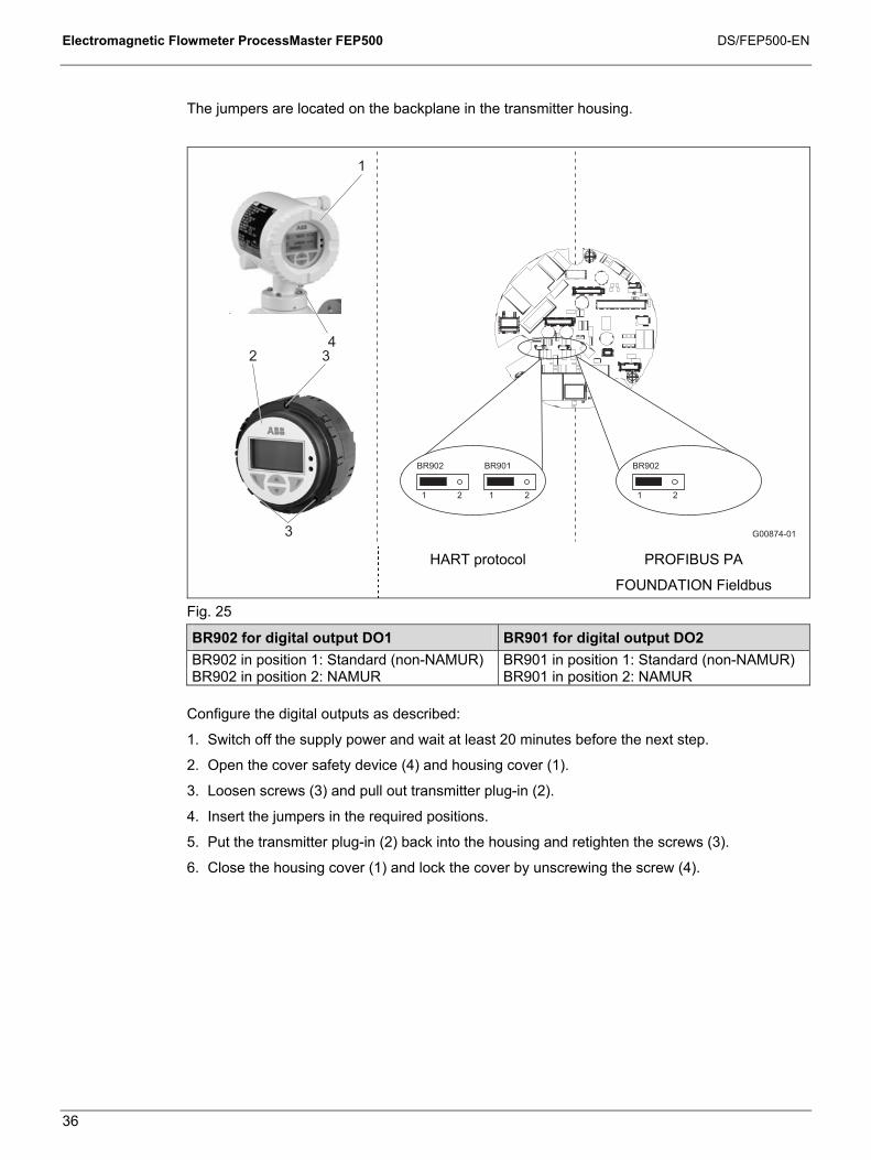
Electromagnetic Flowmeter ProcessMaster FEP500 DS/FEP500-EN
36
The jumpers are located on the backplane in the transmitter housing.
G00874-01
2 3
3
1
4
1 2 1 2
BR902 BR901
1 2
BR902
HART protocol PROFIBUS PA
FOUNDATION Fieldbus
Fig. 25
BR902 for digital output DO1 BR901 for digital output DO2 BR902 in position 1: Standard (non-NAMUR) BR901 in position 1: Standard (non-NAMUR) BR902 in position 2: NAMUR BR901 in position 2: NAMUR
Configure the digital outputs as described:
1. Switch off the supply power and wait at least 20 minutes before the next step.
2. Open the cover safety device (4) and housing cover (1).
3. Loosen screws (3) and pull out transmitter plug-in (2).
4. Insert the jumpers in the required positions.
5. Put the transmitter plug-in (2) back into the housing and retighten the screws (3).
6. Close the housing cover (1) and lock the cover by unscrewing the screw (4).

Electromagnetic Flowmeter ProcessMaster FEP500 DS/FEP500-EN
37
6 Ex-relevant specifications for operation in zones 2, 21, 22 / Div. 2 A
6.1 General
Devices with model names FEP515 and FEP525 are approved for operation in the following potentially explosive areas: • ATEX/IECEx Zone 2, 21, 22 • FM Div.2 • cFM Div.2
Important For detailed information on the individual approvals, refer to Section 1, "ProcessMaster 500 - Overview of technology".
A temperature of 70 °C (158 °F) at the cable entry is assumed for the Ex calculations. Therefore, the cables used for the supply power and the signal inputs and outputs must have a minimum specification of 70 °C (158 °F).
For devices with remote mount design for use in FM / cFM Div. 1 or FM / cFM Div. 2 the signal cable between the flowmeter sensor and the transmitter must have a minimum length of 5 m (16.4 ft).
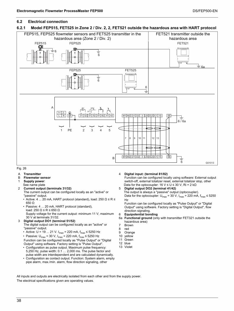
Electromagnetic Flowmeter ProcessMaster FEP500 DS/FEP500-EN
38
6.2 Electrical connection
6.2.1 Model FEP515, FET525 in Zone 2 / Div. 2, 2, FET521 outside the hazardous area with HART protocol
FEP515, FEP525 flowmeter sensors and FET525 transmitter in the hazardous area (Zone 2 / Div. 2)
FET521 transmitter outside the hazardous area
G01013
31 32
A24 V
51 52 81 82 41 42L N
1+ 2-
M1 M2 D1 D2 3 2S E2 E1 1S
M1 M2 D1 D2 3 E2 E1 SEB
2 3 4 51 PE
7 8 9 10 11 12 13
6 / 6a
SE+ - + - + - + -
6
6
6
6
6a
2S 1S
6
FEP515 FEP525
FEP525 FET525
FET521
Fig. 26
A Transmitter B Flowmeter sensor 1 Supply power:
See name plate 2 Current output (terminals 31/32) The current output can be configured locally as an "active" or
"passive" output. • Active: 4 ... 20 mA, HART protocol (standard), load: 250 Ω ≤ R ≤
650 Ω • Passive: 4 ... 20 mA, HART protocol (standard),
load: 250 Ω ≤ R ≤ 650 Ω Supply voltage for the current output: minimum 11 V, maximum 30 V at terminals 31/32.
3 Digital output DO1 (terminal 51/52) The digital output can be configured locally as an "active" or
"passive" output. • Active: U = 19 ... 21 V. Imax = 220 mA, fmax ≤ 5250 Hz • Passive: Umax = 30 V, Imax = 220 mA, fmax ≤ 5250 Hz
Function can be configured locally as "Pulse Output" or "Digital Output" using software. Factory setting is "Pulse Output". • Configuration as pulse output. Maximum pulse frequency:
5,250 Hz, pulse width: 0.1 … 2,000 ms. The pulse factor and pulse width are interdependent and are calculated dynamically.
• Configuration as contact output. Function: System alarm, empty pipe alarm, max./min. alarm, flow direction signaling, other
4 Digital input: (terminal 81/82) Function can be configured locally using software: External output
switch-off, external totalizer reset, external totalizer stop, other Data for the optocoupler: 16 V ≤ U ≤ 30 V, Ri = 2 kΩ
5 Digital output DO2 (terminal 41/42) The output is always a "passive" output (optocoupler).
Data for the optocoupler: Umax = 30 V, Imax = 220 mA, fmax ≤ 5250 Hz
Function can be configured locally as "Pulse Output" or "Digital Output" using software. Factory setting is "Digital Output", flow direction signaling.
6 Equipotential bonding 6a Functional ground (only with transmitter FET321 outside the
hazardous area) 7 Brown 8 red 9 Orange 10 yellow 11 Green 12 blue 13 Violet
All inputs and outputs are electrically isolated from each other and from the supply power. The electrical specifications given are operating values.
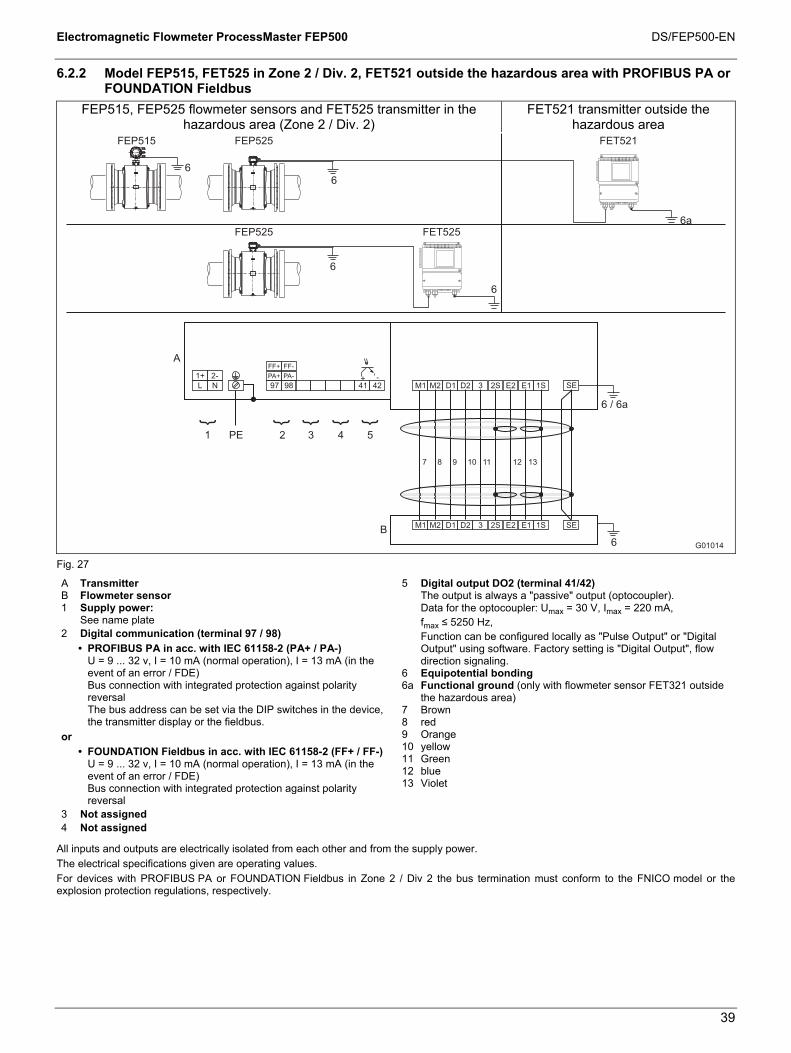
Electromagnetic Flowmeter ProcessMaster FEP500 DS/FEP500-EN
39
6.2.2 Model FEP515, FET525 in Zone 2 / Div. 2, FET521 outside the hazardous area with PROFIBUS PA or FOUNDATION Fieldbus
FEP515, FEP525 flowmeter sensors and FET525 transmitter in the hazardous area (Zone 2 / Div. 2)
FET521 transmitter outside the hazardous area
G01014
97 98
A
41 42L N
1+ 2-
M1 M2 D1 D2 3 2S E2 E1 1S
M1 M2 D1 D2 3 E2 E1 SEB
2 3 4 51 PE
7 8 9 10 11 12 13
6 / 6a
SE+ -
6
6
6
6
6a
2S 1S
6
FEP515 FEP525
FEP525 FET525
FET521
PA+ PA-
FF+ FF-
Fig. 27
A Transmitter B Flowmeter sensor 1 Supply power: See name plate 2 Digital communication (terminal 97 / 98)
• PROFIBUS PA in acc. with IEC 61158-2 (PA+ / PA-) U = 9 ... 32 v, I = 10 mA (normal operation), I = 13 mA (in the event of an error / FDE) Bus connection with integrated protection against polarity reversal The bus address can be set via the DIP switches in the device, the transmitter display or the fieldbus.
or • FOUNDATION Fieldbus in acc. with IEC 61158-2 (FF+ / FF-)
U = 9 ... 32 v, I = 10 mA (normal operation), I = 13 mA (in the event of an error / FDE) Bus connection with integrated protection against polarity reversal
3 Not assigned 4 Not assigned
5 Digital output DO2 (terminal 41/42) The output is always a "passive" output (optocoupler). Data for the optocoupler: Umax = 30 V, Imax = 220 mA,
fmax ≤ 5250 Hz, Function can be configured locally as "Pulse Output" or "Digital
Output" using software. Factory setting is "Digital Output", flow direction signaling.
6 Equipotential bonding 6a Functional ground (only with flowmeter sensor FET321 outside
the hazardous area) 7 Brown 8 red 9 Orange 10 yellow 11 Green 12 blue 13 Violet
All inputs and outputs are electrically isolated from each other and from the supply power. The electrical specifications given are operating values. For devices with PROFIBUS PA or FOUNDATION Fieldbus in Zone 2 / Div 2 the bus termination must conform to the FNICO model or the explosion protection regulations, respectively.

Electromagnetic Flowmeter ProcessMaster FEP500 DS/FEP500-EN
40
6.3 Electrical data for operation in Zone 2 / Div. 2
6.3.1 Devices with HART protocol
When operating in potentially explosive areas, observe the following electrical data for the signal inputs and outputs of the transmitter. For the correct current output design (active/passive), see the marking contained in the device's terminal box.
Model: FEP515 or FET525
Ex data Operating values Ex n/NI
Signal inputs and outputs Ui [V] Ii [mA] Ui [V] Ii [mA] Current output Active/passive Terminal 31/32
30 30 30 30
Digital output DO1 Active/passive Terminal 51/52
30 220 30 220
Digital output DO2 passive Terminal 41/42
30 220 30 220
Digital input DI Terminal 81/82
30 10 30 10 All inputs and outputs are electrically isolated from each other and from the supply power.
6.3.2 Devices with PROFIBUS PA or FOUNDATION Fieldbus
When operating in potentially explosive areas, observe the following electrical data for the signal inputs and outputs of the transmitter. For the correct design (PROFIBUS PA or FOUNDATION Fieldbus), see the marking contained in the device's terminal box.
Model: FEP515 or FET525
Operating values Ex data Explosion protection type Ex n, NI and FNICO
Inputs and outputs
UN [V]
IN [mA]
Ui [V]
Ii [mA]
Pi [mW]
Ci [nF]
CiPA [nF]
Li [µH]
Passive digital output DO2 Terminal 41/42
30 220 - - - - - -
Fieldbus Terminal 97/98 32 30 32 500 1) 7000 1) 1 1 5
1) Single-channel or multi-channel barriers (supply isolators) with resistance characteristic must be used.
6.4 Temperature values
Model name Surface temperature FEP515 70 °C (158 °F) FEP525 85 °C (185 °F) FET525 70 °C (158 °F)
The surface temperature depends on the fluid temperature. With increasing fluid temperature > 70 °C (> 158 °F) or > 85 °C (> 185 °F) the surface temperature also increases to the level of the fluid temperature.

Electromagnetic Flowmeter ProcessMaster FEP500 DS/FEP500-EN
41
Table 1: Fluid temperature as a function of lining and flange material
Models FEP515/FEP525
Materials Fluid temperature (operating values) Lining Flange Minimum Maximum
Hard rubber Steel -10 °C (14 °F) 90 °C (194 °F)
80 °C (176 °F) 1)
Hard rubber Stainless steel -15 °C (5 °F) 90 °C (194 °F)
80 °C (176 °F) 1) Soft rubber Steel -10 °C (14 °F) 60 °C (140 °F) Soft rubber Stainless steel -15 °C (5 °F) 60 °C (140 °F)
PTFE Steel -10 °C (14 °F) 130 °C (266 °F) PTFE Stainless steel -25 °C (-13 °F) 130 °C (266 °F) PFA Steel -10 °C (14 °F) 180 °C (356 °F) PFA Stainless steel -25 °C (-13 °F) 180 °C (356 °F)
Thick PTFE Steel -10 °C (14 °F) 180 °C (356 °F) Thick PTFE Stainless steel -25 °C (-13 °F) 180 °C (356 °F) Elastomer 2) Steel -10 °C (14 °F) 130 °C (266 °F) Elastomer 2) Stainless steel -20 °C (-4 °F) 130 °C (266 °F)
ETFE Steel -10 °C (14 °F) 130 °C (266 °F) ETFE Stainless steel -25 °C (-13 °F) 130 °C (266 °F)
1) Only China production site (under preparation) 2) USA production site, only (only for FM / cFM Div 2)

Electromagnetic Flowmeter ProcessMaster FEP500 DS/FEP500-EN
42
Table 2: Fluid temperature (Ex data) for ProcessMaster model FEP515
Ambient temperature - 20 °C ... + 40 °C - 20 °C ... + 50 °C - 20 °C ... + 60 °C
- 40 °C ... + 40 °C 1) - 40 °C ... + 50 °C 1) - 40 °C ... + 60 °C 1) Not thermally
insulated Thermally insulated
Not thermally insulated
Thermally insulated
Not thermally insulated
Thermally insulated
Nom
inal
dia
met
er
Des
ign
Tem
pera
ture
cla
ss
Gas Gas & dust Gas Gas &
dust Gas Gas & dust Gas Gas &
dust Gas Gas & dust Gas Gas &
dust
NT 130 °C 130 °C - - - - - - 130 °C 100 °C 2)
110 °C 3) - - - - - - 80 °C 40 °C - - - - - -
HT T1
180 °C 180 °C 180 °C 180 °C 180 °C 180 °C 180 °C 180 °C 180 °C 40 °C 180 °C 40 °C
NT 130 °C 130 °C - - - - - - 130 °C 100 °C 2)
110 °C 3) - - - - - - 80 °C 40 °C - - - - - -
HT T2
180 °C 180 °C 180 °C 180 °C 180 °C 180 °C 180 °C 180 °C 180 °C 40 °C 180 °C 40 °C
NT 130 °C 130 °C - - - - - - 130 °C 100 °C 2)
110 °C 3) - - - - - - 80 °C 40 °C - - - - - -
HT T3
180 °C 180 °C 180 °C 180 °C 180 °C 180 °C 180 °C 180 °C 180 °C 40 °C 180 °C 40 °C
NT 130 °C 130 °C - - - - - - 130 °C 100 °C 2)
110 °C 3) - - - - - - 80 °C 40 °C - - - - - -
Pro
cess
Mas
ter D
N 3
... D
N 2
000
Hyg
ieni
cMas
ter D
N 3
... D
N 1
00
HT T4
130 °C 130 °C 130 °C 130 °C 130 °C 130 °C 130 °C 130 °C 130 °C 40 °C 130 °C 40 °C
1) Low-temperature version (option) 2) Temperature values for ProcessMaster 3) Temperature values for HygienicMaster NT standard version, Tmedium maximum 130 °C (266 °F) HT high-temperature version, Tmedium maximum 180 °C (356 °F) Not thermally insulated: The flowmeter sensor is not surrounded by pipe insulation material. Thermally insulated: The flowmeter sensor is surrounded by pipe insulation material.
Important The standard version includes explosion protection for gases and dust. • If the installation location for the device is classified as a potentially explosive area for gases and dust, the
temperature data in the "Gas & dust" columns in the table must be taken into consideration. • If the installation location for the device is classified as a potentially explosive area for gases only, the temperature
data in the "Gas" columns in the table must be taken into consideration.

Electromagnetic Flowmeter ProcessMaster FEP500 DS/FEP500-EN
43
Table 3: Fluid temperature (Ex data) for ProcessMaster Model FEP525
Ambient temperature - 20 °C ... + 40 °C - 20 °C ... + 50 °C - 20 °C ... + 60 °C
- 40 °C ... + 40 °C 1) - 40 °C ... + 50 °C 1) - 40 °C ... + 60 °C 1) Not thermally
insulated Thermally insulated
Not thermally insulated
Thermally insulated
Not thermally insulated
Thermally insulated
Nom
inal
dia
met
er
Des
ign
Tem
pera
ture
cl
ass
Gas Gas & dust Gas Gas &
dust Gas Gas & dust Gas Gas &
dust Gas Gas & dust Gas Gas &
dust
NT 130 °C 130 °C - - - - - - 130 °C 130 °C - - - - - - 110 °C 2) 120 °C 3)
110 °C - - - - - -
HT T1
180 °C 180 °C 180 °C 180 °C 180 °C 180 °C 180 °C 180 °C 180 °C 180 °C 180 °C 180 °C
NT 130 °C 130 °C - - - - - - 130 °C 130 °C - - - - - - 110 °C 2) 120 °C 3)
110 °C - - - - - -
HT T2
180 °C 180 °C 180 °C 180 °C 180 °C 180 °C 180 °C 180 °C 180 °C 180 °C 180 °C 180 °C
NT 130 °C 130 °C - - - - - - 130 °C 130 °C - - - - - - 110 °C 2) 120 °C 3)
110 °C - - - - - -
HT T3
180 °C 180 °C 180 °C 180 °C 180 °C 180 °C 180 °C 180 °C 180 °C 180 °C 180 °C 180 °C
NT 130 °C 130 °C - - - - - - 130 °C 130 °C - - - - - - 110 °C 2) 120 °C 3)
110 °C - - - - - -
HT T4
130 °C 130 °C 130 °C 130 °C 130 °C 130 °C 130 °C 130 °C 130 °C 130 °C 130 °C 130 °C NT 95 °C 95 °C - - - - - - 95 °C 95 °C - - - - - - 95 °C 95 °C - - - - - - HT
T5 95 °C 95 °C 95 °C 95 °C 95 °C 95 °C 95 °C 95 °C 95 °C 95 °C 95 °C 95 °C
NT 80 °C 80 °C - - - - - - 80 °C 80 °C - - - - - - 80 °C 80 °C - - - - - -
Pro
cess
Mas
ter D
N 3
... D
N 2
000
Hyg
ieni
cMas
ter D
N 3
... D
N 1
00
HT T6
80 °C 80 °C 80 °C 80 °C 80 °C 80 °C 80 °C 80 °C 80 °C 80 °C 80 °C 80 °C 1) Low-temperature version (option) 2) Temperature values for ProcessMaster 3) Temperature values for HygienicMaster NT standard version, Tmedium maximum 130 °C (266 °F) HT high-temperature version, Tmedium maximum 180 °C (356 °F) Not thermally insulated: The flowmeter sensor is not surrounded by pipe insulation material. Thermally insulated: The flowmeter sensor is surrounded by pipe insulation material.
Important The standard version includes explosion protection for gases and dust. • If the installation location for the device is classified as a potentially explosive area for gases and dust, the
temperature data in the "Gas & dust" columns in the table must be taken into consideration. • If the installation location for the device is classified as a potentially explosive area for gases only, the temperature
data in the "Gas" columns in the table must be taken into consideration.

Electromagnetic Flowmeter ProcessMaster FEP500 DS/FEP500-EN
44
7 Explosion protection specifications for operation in areas with combustible dust
7.1 Information about using the device in areas with combustible dust
The device is approved for use in potentially explosive areas (gas and dust).
The Ex certification is provided on the name plate.
Risk of explosion! The dust explosion protection is also provided by the housing. Modifications to the housing are not allowed (e.g., removing or omitting parts).
7.1.1 Maximum Allowable Surface Temperature
Model name Maximum surface temperature
FEP525 T 85 °C (185 °F) ... Tmedium
FEP515 T 70 °C (158 °F) ... Tmedium
FET525 T 70 °C (158 °F)
The maximum surface temperature is applicable to dust layers of up to 5 mm (0.20 inch) in thickness. The minimum permissible ignition and smoldering temperatures of the dust atmosphere should be calculated in accordance with IEC61241ff.
With thicker dust layers, the maximum permissible surface temperature must be reduced. The dust can be conductive or non-conductive. IEC61241ff must be observed.
7.1.2 Min. signal cable length
In explosion protection areas, the signal cable cannot be shorter than 5 m (16.4 ft).

Electromagnetic Flowmeter ProcessMaster FEP500 DS/FEP500-EN
45
Change from one to two columns
8 Installation requirements Change from one to two columns
8.1 Grounding
The flowmeter sensor must be connected to ground potential. For technical reasons, this potential should be identical to the potential of the metering fluid. For plastic or insulated lined pipelines, the fluid is grounded by installing ground plates. When there are stray potentials present in the pipeline, a ground plate is recommended on both ends of the meter sensor.
8.2 Mounting
The following points must be observed for the installation: • The meter tube must always be completely full. • The flow direction must correspond to the identification if present. • The maximum torque for all flange connections must be complied
with. The max torque depends on the temperature, pressure, material of the flange bolts and gaskets and has to be choosen accordingly.
• The devices must be installed without mechanical tension (torsion, bending).
• Flowmeters with coplanar counter flanges may only be installed with suitable seals.
• Use flange seals made from a compatible material for the fluid and fluid temperatures.
• Seals must not extend into the flow area since possible turbulence could influence the device accuracy.
• The pipeline may not exert any unallowable forces and torques on the device.
• Do not remove the plugs in the cable connectors until you are ready to install the electrical cable.
• Install the separate converter at a largely vibration-free location. • Do not expose the converter to direct sunlight or provide for
appropriate sun protection where necessary.
The device measures the flowrate in both directions. Forward flow is the factory setting, as shown in Fig. 28.
Fig. 28
8.2.1 Electrode axis
Electrode axis (1) should be horizontal if at all possible or no more that 45° from horizontal.
G00041
max. 45°
1
Fig. 29
8.2.2 In- and outlet pipe sections
Straight inlet section Straight outlet section ≥ 3 x DN ≥ 2 x DN
DN = Flowmeter sensor size • Do not install fittings, manifolds, valves etc. directly in front of the
meter tube (1). • Butterfly valves must be installed so that the valve plate does not
extend into the flowmeter sensor. • Valves or other turn-off components should be installed in the
outlet pipe section (2). • For compliance with the measuring accuracy, observe the inlet
and outlet pipe sections.
G00037
1 2
3xDN 2xDN Fig. 30
8.2.3 Vertical connections
• Vertical installation for measurement of abrasive fluids, flow preferably from below to above.
Fig. 31
8.2.4 Horizontal connections
• Meter tube must always be completely full. • Provide for a slight incline of the connection for degassing.
G00038
3°
Fig. 32

Electromagnetic Flowmeter ProcessMaster FEP500 DS/FEP500-EN
46
8.2.5 Free inlet or outlet
• Do not install the flowmeter at the highest point or in the draining- off side of the pipeline, flowmeter runs empty, air bubbles can form (1).
• Provide for a siphon fluid intake for free inlets or outlets so that the pipeline is always full (2).
G00040
1
2
Fig. 33
8.2.6 Strongly contaminated fluids
• For strongly contaminated fluids, a bypass connection according to the figure is recommended so that operation of the system can continue to run without interruption the during the mechanical cleaning.
G00042 Fig. 34
8.2.7 Installation in the vicinity of pumps
• For flowmeter primaries which are to be installed in the vicinity of pumps or other vibration generating equipment, the utilization of mechanical snubbers is advantageous.
G00561 Fig. 35
8.2.8 Installing the high temperature design
The high temperature design allows for complete thermal insulation of the sensor. The pipeline and sensor must be insulated after installing the unit according to the following illustration.
G00654
1
Fig. 36
1 Insulation
8.2.9 Installation in pipelines with larger nominal diameters
Determine the resulting pressure loss when using reduction pieces (1): 1. Calculate the diameter ratio d/D. 2. Determine the flow velocity based on the flow range nomograph
(Fig. 38). 3. Read the pressure drop on the Y-axis in Fig. 38.
Fig. 37 1 d V Δp D
= Flange transition piece = Inside diameter of the flowmeter = flow velocity [m/s] = pressure loss [mbar] = Inside diameter of the pipeline
Nomograph for pressure drop calculations For flange transition piece with α/2 = 8°
Fig. 38
8.2.10 Devices with extended diagnostic functions
For devices with extended diagnostic functions different installation conditions may be valid. For further information read and observe chapter 3 “Extended diagnostic functions”.
Change from one to two columns

Electromagnetic Flowmeter ProcessMaster FEP500 DS/FEP500-EN
47
9 Dimensions
9.1 Flange, DN 3 ... 125 (1/10 ... 5")
Fig. 39: Dimensions in mm (inch) Flange in acc. with DIN/EN 1092-1 7)
Dimensions [mm] Approx. weight [kg] DN PN 1) D L 2) 3) F 4) C E 4) G 4) Integral mount design Remote mount design
3 ... 8 5) 10 ... 40 90 200 255 82 188 143 7 5 10 10 ... 40 90 200 255 82 188 143 7 5 15 10 ... 40 95 200 255 82 188 143 8 6 20 10 ... 40 105 200 255 82 188 143 8 6 25 10 ... 40 115 200 255 82 188 143 9 7 32 10 ... 40 140 200 262 92 195 150 10 8 40 10 ... 40 150 200 262 92 195 150 11 9 50 10 ... 40 165 200 268 97 201 156 12 10 65 10 ... 40 185 200 279 108 212 167 15 13 80 10 ... 40 200 200 279 108 212 167 17 15
100 10 ... 16 220 250 301 122 234 189 19 17 25 ... 40 235 250 301 122 234 189 23 21
125 10 ... 16 250 250 311 130 244 199 22 20 25 ... 40 270 250 311 130 244 199 29 27
Tolerance L: +0 / -3 mm
Dimensions [inch] Approx. weight [lb] DN (inch) PN 1) D L 2) 3) F 4) C E 4) G 4) Integral mount design Remote mount design3 ... 8 5)
(1/8 ... 5/16) 10 ... 40 3.54 7.87 10.04 3.23 7.40 5.63 15.4 11
10 (3/8) 10 ... 40 3.54 7.87 10.04 3.23 7.40 5.63 15.4 11 15 (1/2) 10 ... 40 3.74 7.87 10.04 3.23 7.40 5.63 17.6 13.2 20 (3/4) 10 ... 40 4.13 7.87 10.04 3.23 7.40 5.63 17.6 13.2 25 (1) 10 ... 40 4.53 7.87 10.04 3.23 7.40 5.63 19.8 15.4
32 (1 1/4) 10 ... 40 5.51 7.87 10.31 3.62 7.68 5.91 22 17.6 40 (1 1/2) 10 ... 40 5.91 7.87 10.31 3.62 7.68 5.91 24.3 19.8
50 (2) 10 ... 40 6.50 7.87 10.55 3.82 7.91 6.14 26.5 22 65 (2 1/2) 10 ... 40 7.28 7.87 10.98 4.25 8.35 6.57 33.1 28.7
80 (3) 10 ... 40 7.87 7.87 10.98 4.25 8.35 6.57 37.5 33.1 100 (4) 10 ... 16 8.66 9.84 11.85 4.80 9.21 7.44 41.9 37.5
25 ... 40 9.25 9.84 11.85 4.80 9.21 7.44 50.7 46.3 125 (5) 10 ... 16 9.84 9.84 12.24 5.12 9.61 7.83 48.5 44.1
25 ... 40 10.63 9.84 12.24 5.12 9.61 7.83 63.9 59.5 Tolerance L: +0 / -0.018 inch

Electromagnetic Flowmeter ProcessMaster FEP500 DS/FEP500-EN
48
Flange in acc. with ASME B16.5 Dimensions [mm] Approx. weight [kg]
CL150 CL300
ISO 133359
US installation
length ISO
133359 US
installation length
DN Inch D L 2) 3) 9) L 2) 3) D L 2) 3) 9) L 2) 3) F 4) C E 4) G 4)
Integral mount design
Remote mount design
3 ... 8 1/8 ... 5/16 6) 89 200 - 96 200 - 255 82 188 143 7 5 10 3/8 6) 89 200 - 96 200 - 255 82 188 143 7 5 15 1/2 89 200 200 96 200 229 255 82 188 143 8 6 20 3/4 98 200 - 118 200 - 255 82 188 143 8 6 25 1 108 200 200 124 200 229 255 82 188 143 9 7 32 1 1/4 118 200 - 134 200 - 262 92 195 150 10 8 40 1 1/2 127 200 200 156 200 229 262 92 195 150 11 9 50 2 153 200 200 165 200 254 268 97 201 156 12 10 65 2 1/2 178 200 - 191 200 - 279 108 212 167 13 / 15 8) 11 / 13 8) 80 3 191 200 200 210 200 229 279 108 212 167 17 / 19 8) 15 / 17 8)
100 4 229 250 250 254 250 280 301 122 234 189 21 / 30 8) 19 / 28 8) 125 5 254 250 - 280 250 - 311 130 244 199 22 / 35 8) 20 / 33 8)
Tolerance L: +0 / -3 mm
Dimensions [inch] Approx. weight [lb] CL150 CL300
ISO 133359
US installation
length ISO
133359 US
installation length
DN Inch D L 2) 3) 9) L 2) 3) D L 2) 3) 9) L 2) 3) F 4) C E 4) G 4)
Integral mount design
Remote mount design
3 ... 8 1/8 ... 5/16 6) 3.5 7.87 - 3.78 7.87 - 10.04 3.23 7.4 5.63 15 11 10 3/8 6) 3.5 7.87 - 3.78 7.87 - 10.04 3.23 7.4 5.63 15 11 15 1/2 3.5 7.87 7.87 3.78 7.87 9.02 10.04 3.23 7.4 5.63 18 13 20 3/4 3.86 7.87 - 4.65 7.87 - 10.04 3.23 7.4 5.63 18 13 25 1 4.25 7.87 7.87 4.88 7.87 9.02 10.04 3.23 7.4 5.63 20 15 32 1 1/4 4.65 7.87 - 5.28 7.87 - 10.31 3.62 7.68 5.91 22 18 40 1 1/2 5 7.87 7.87 6.14 7.87 9.02 10.31 3.62 7.68 5.91 24 20 50 2 6.02 7.87 7.87 6.5 7.87 10 10.55 3.82 7.91 6.14 16 22 65 2 1/2 7.01 7.87 - 7.52 7.87 - 10.98 4.25 8.35 6.57 29 / 33 8) 24 / 29 8) 80 3 7.52 7.87 7.87 8.27 7.87 9.02 10.98 4.25 8.35 6.57 38 / 42 8) 33 / 38 8)
100 4 9.02 9.84 9.84 10 9.84 11.02 11.85 4.8 9.21 7.44 46 / 66 8) 42 / 62 8) 125 5 10 9.84 - 11.02 9.84 - 12.24 5.12 9.61 199 49 / 77 8) 44 / 73 8)
Tolerance L: +0 / -0.118 inch 1) Other pressure ratings upon request. 2) If a grounding plate is installed (attached to one side of the flange), this increases dimension L as follows: DN 3 ... 100 by 3 mm (0.118 inch; DN 125 by 5 mm (0.197 inch). 3) If protection plates are installed (attached to both sides of the flange), this increases dimension L as follows: DN 3 ... 100 by 6 mm (0.236 inch; DN 125 by 10 mm (0.394 inch). 4) Depending on the device design, the dimensions change according to the following table.
Device design Dimension E, F Dimension G Without explosion protection
Standard temperature design 0 0
High temperature version +127 mm (+5 inch) +127 mm (+5 inch) Explosion protection Zone 1, Div. 1
Standard temperature design +74 mm (+2.91 inch) +47 mm (+1.85 inch)
High temperature version +127 mm (+5 inch) +174 mm (+6.85 inch) Explosion protection Zone 2, Div. 2
Standard temperature design 0 0
High temperature version +127 mm (+5 inch) +127 mm (+5 inch)
5) Connection flange DN 10 6) Connection flange 1/2" 7) Connecting dimensions in acc. with EN 1092-1. For DN 65, PN 16 in acc. with EN 1092-1, please order PN 40. 8) Weights for CL150 / CL300. 9) For devices with ordering code “Installation length JN” (China production site) the installation length corresponds to the ISO installation length.
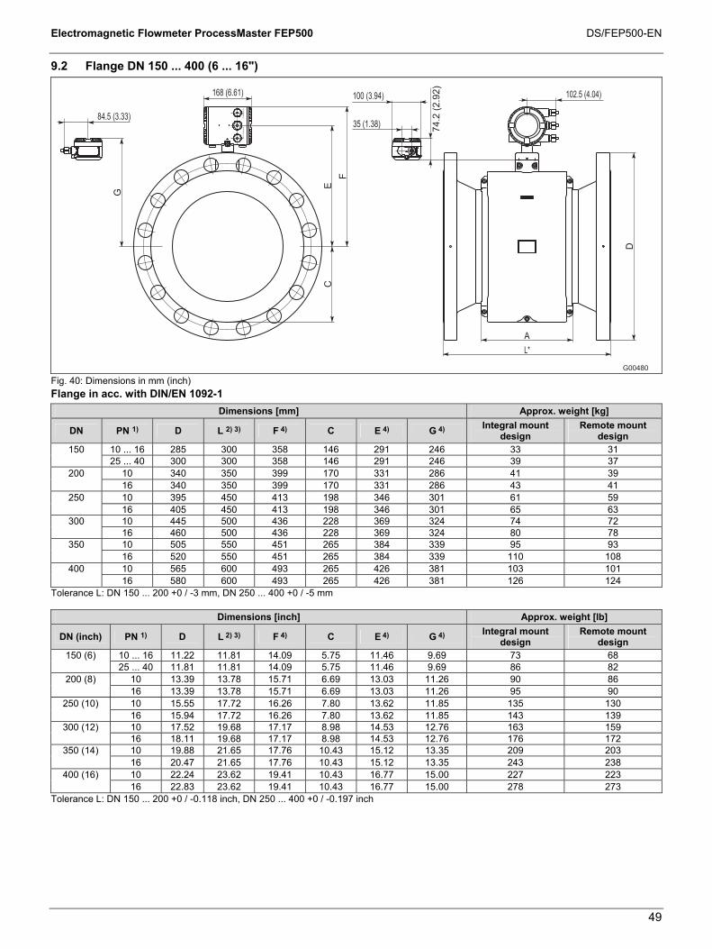
Electromagnetic Flowmeter ProcessMaster FEP500 DS/FEP500-EN
49
9.2 Flange DN 150 ... 400 (6 ... 16")
Fig. 40: Dimensions in mm (inch) Flange in acc. with DIN/EN 1092-1
Dimensions [mm] Approx. weight [kg]
DN PN 1) D L 2) 3) F 4) C E 4) G 4) Integral mount design
Remote mount design
150 10 ... 16 285 300 358 146 291 246 33 31 25 ... 40 300 300 358 146 291 246 39 37
200 10 340 350 399 170 331 286 41 39 16 340 350 399 170 331 286 43 41
250 10 395 450 413 198 346 301 61 59 16 405 450 413 198 346 301 65 63
300 10 445 500 436 228 369 324 74 72 16 460 500 436 228 369 324 80 78
350 10 505 550 451 265 384 339 95 93 16 520 550 451 265 384 339 110 108
400 10 565 600 493 265 426 381 103 101 16 580 600 493 265 426 381 126 124
Tolerance L: DN 150 ... 200 +0 / -3 mm, DN 250 ... 400 +0 / -5 mm
Dimensions [inch] Approx. weight [lb]
DN (inch) PN 1) D L 2) 3) F 4) C E 4) G 4) Integral mount design
Remote mount design
150 (6) 10 ... 16 11.22 11.81 14.09 5.75 11.46 9.69 73 68 25 ... 40 11.81 11.81 14.09 5.75 11.46 9.69 86 82
200 (8) 10 13.39 13.78 15.71 6.69 13.03 11.26 90 86 16 13.39 13.78 15.71 6.69 13.03 11.26 95 90
250 (10) 10 15.55 17.72 16.26 7.80 13.62 11.85 135 130 16 15.94 17.72 16.26 7.80 13.62 11.85 143 139
300 (12) 10 17.52 19.68 17.17 8.98 14.53 12.76 163 159 16 18.11 19.68 17.17 8.98 14.53 12.76 176 172
350 (14) 10 19.88 21.65 17.76 10.43 15.12 13.35 209 203 16 20.47 21.65 17.76 10.43 15.12 13.35 243 238
400 (16) 10 22.24 23.62 19.41 10.43 16.77 15.00 227 223 16 22.83 23.62 19.41 10.43 16.77 15.00 278 273
Tolerance L: DN 150 ... 200 +0 / -0.118 inch, DN 250 ... 400 +0 / -0.197 inch

Electromagnetic Flowmeter ProcessMaster FEP500 DS/FEP500-EN
50
Flange in acc. with ASME B16.5
Dimensions [mm] Approx. weight [kg] CL150 CL300
ISO 13359
US installation length
ISO 13359
US installation length
DN Inch D L 2) 3) 6) L 2) 3) D L 2) 3) 6) L 2) 3) F 4) C E 4) G 4)
Integral mount design
Remote mount design
150 6 280 300 300 318 300 300 358 146 291 246 33 / 47 5) 31 / 45 5) 200 8 343 350 350 381 350 350 399 170 331 286 50 / 72 5) 48 / 70 5) 250 10 407 450 450 445 450 450 413 198 346 301 70 / 105 5) 68 / 103 5) 300 12 483 500 500 521 500 500 436 228 369 324 105 / 150 5) 103 / 148 5) 350 14 533 550 533 584 550 533 451 265 384 339 105 / 140 5) 103 / 138 5) 400 16 597 600 610 647 600 610 493 265 426 381 175 / 265 5) 173 / 263 5)
Tolerance L: DN 150 ... 200 +0 / -3 mm, DN 250 ... 400 +0 / -5 mm
Dimensions [inch] Approx. weight [lb] CL150 CL300
ISO 13359
US installation length
ISO 13359
US installation length
DN Inch D L 2) 3) 6) L 2) 3) D L 2) 3) 6) L 2) 3) F 4) C E 4) G 4)
Integral mount design
Remote mount design
150 6 11.02 11.81 11.81 12.52 11.81 11.81 14.09 5.75 11.46 9.69 73 / 104 5) 68 / 99 5) 200 8 13.5 13.78 13.78 15 13.78 13.78 15.71 6.69 13.03 11.26 110 / 158 5) 106 / 154 5) 250 10 16.02 17.72 17.72 17.52 17.72 17.72 16.26 7.8 13.62 11.85 154 / 232 5) 150 / 227 5) 300 12 19.02 19.69 19.69 20.51 19.69 19.69 17.17 8.98 14.53 12.76 232 / 150 5) 227 / 326 5) 350 14 20.98 21.65 20.98 22.99 21.65 20.98 17.76 10.43 15.12 13.35 232 / 140 5) 227 / 304 5) 400 16 23.5 23.62 24.02 25.47 23.62 24.02 19.41 10.43 16.77 15 386 / 584 5) 381 / 580 5)
Tolerance L: DN 150 ... 200 +0 / -0.118 inch, DN 250 ... 400 +0 / -0.197 inch 1) Other pressure ratings upon request. 2) If a grounding plate is installed (attached to one side of the flange), this increases dimension L by 5 mm (0.197 inch). 3) If protection plates are installed (attached to both sides of the flange), this increases dimension L by 10 mm (0.394 inch). 4) Depending on the device design, the dimensions change according to the following table.
Device design Dimension E, F Dimension G Without explosion protection
Standard temperature design 0 0
High temperature version +127 mm (+5 inch) +127 mm (+5 inch) Explosion protection Zone 1, Div. 1
Standard temperature design +74 mm (+2.91 inch) +47 mm (+1.85 inch)
High temperature version +127 mm (+5 inch) +174 mm (+6.85 inch) Explosion protection Zone 2, Div. 2
Standard temperature design 0 0
High temperature version +127 mm (+5 inch) +127 mm (+5 inch)
5) Weights for CL150 / CL300. 6) For devices with ordering code “Installation length JN” (China production site) the installation length corresponds to the ISO installation length.

Electromagnetic Flowmeter ProcessMaster FEP500 DS/FEP500-EN
51
9.3 Flange DN 450 ... 2000 (18 ... 80")
Fig. 41: Dimensions in mm (inch) Flange in acc. with DIN/EN 1092-1
Dimensions [mm] Approx. weight [kg]
DN PN 1) D L 2) 3) F 4) C E 4) G 4) Integral mount design
Remote mount design
500 10 670 650 501 310 434 389 190 188 16 715 650 501 310 434 389 240 238
600 10 780 780 552 361 485 440 246 244 16 840 780 552 361 485 440 318 316
700 10 895 910 596 405 529 484 320 318 16 910 910 596 405 529 484 440 438
800 10 1015 1040 646 455 579 534 420 418 16 1025 1040 646 455 579 534 490 488
900 10 1115 1170 696 505 629 584 505 503 16 1125 1170 696 505 629 584 590 588
1000 10 1230 1300 746 555 679 634 690 688 16 1255 1300 746 555 679 634 850 848
1200 6 1405 1560 856 660 789 742 700 698 10 1455 1560 856 660 789 742 930 928
1400 6 1630 1820 950 755 884 838 810 808 10 1675 1820 950 755 884 838 1210 1208
1600 6 1830 2080 1060 865 994 948 1180 1178 10 1915 2080 1060 865 994 948 1630 1628
1800 6 2045 2340 1176 980 1109 1062 1490 1488 10 2115 2340 1176 980 1109 1062 2230 2228
2000 6 2265 2600 1286 1090 1219 1172 1880 1878 10 2325 2600 1286 1090 1219 1172 2650 2648
Tolerance L: DN 450 ... 500 +0 / -5 mm, DN 600 ... 2000 +0 / -10 mm

Electromagnetic Flowmeter ProcessMaster FEP500 DS/FEP500-EN
52
Dimensions [inch] Approx. weight [lb]
DN (inch) PN 1) D L 2) 3) F 4) C E 4) G 4) Integral mount design Remote mount design 500 (20) 10 26.38 25.59 19.72 12.20 17.09 15.31 432 428
16 28.15 25.59 19.72 12.2 17.09 15.31 529 525 600 (24) 10 30.71 30.71 21.73 14.21 19.09 17.32 608 604
16 33.07 30.71 21.73 14.21 19.09 17.32 701 697 700 (28) 10 35.24 35.83 23.46 15.94 20.83 19.06 703 699
16 35.83 35.83 23.46 15.94 20.83 19.06 970 966 800 (32) 10 39.96 40.94 25.43 17.91 22.80 21.02 902 897
16 40.35 40.94 25.43 17.91 22.8 21.02 1080 1076 900 (36) 10 43.90 46.06 27.40 19.88 24.76 22.99 1073 1069
16 44.29 46.06 27.4 19.88 24.76 22.99 1300 1296 1000 (40) 10 48.43 51.18 29.37 21.85 26.73 24.96 1276 1272
16 49.41 51.18 29.37 21.85 26.73 24.96 1874 1869 1200 (48) 6 55.31 61.42 33.7 25.98 31.06 29.21 1543 1538
10 57.28 61.42 33.7 25.98 31.06 29.21 2050 2046 1400 (54) 6 64.17 71.65 37.4 29.72 34.8 32.99 1786 1781
10 65.94 71.65 37.4 29.72 34.8 32.99 2668 2663 1600 (66) 6 72.05 81.89 41.73 34.06 39.13 37.32 2602 2597
10 75.39 81.89 41.73 34.06 39.13 37.32 3593 3589 1800 (72) 6 80.51 92.13 46.3 38.58 43.66 41.81 3285 3280
10 83.27 92.13 46.3 38.58 43.66 41.81 4916 4912 2000 (80) 6 89.17 102.36 50.63 42.91 47.99 46.14 4145 4140
10 91.54 102.36 50.63 42.91 47.99 46.14 5842 5838 Tolerance L: DN 500 +0 / -0.197 inch, DN 600 ... 2000 +0 / -0.394 inch Flange up to DN 600 (24") in acc. with ASME B16.5, flange DN 700 ... 1000 (28 ... 40") in acc. with ASME B16.47, Series B
Approx. weight [kg] Dimensions [mm] Integral mount
design Remote mount
design
CL150 ISO installation length
US installation length CL150 CL150
DN Inch D L 2) 3) 5) L 2) 3) F 4) C E 4) G 4) Approx. kg Approx. kg 450 18 635 686 686 501 310 434 389 260 258 500 20 699 762 762 501 310 434 389 300 298 600 24 813 914 914 552 361 485 440 425 423 700 28 837 910 - 596 405 529 484 350 348 800 32 942 1040 - 646 455 579 534 500 498 900 36 1057 1170 - 696 505 629 584 680 678
1000 40 1380 1300 - 746 555 679 634 880 878 Tolerance L: DN 450 ... 500 +0 / -5 mm, DN 600 ... 2000 +0 / -10 mm
Approx. weight [lb] Dimensions [inch] Integral mount
design Remote mount
design
CL150 ISO installation length
US installation length CL150 CL150
DN Inch D L 2) 3) 5) L 2) 3) F 4) C E 4) G 4) Approx. lb Approx. lb 450 18 25.0 27.01 27.01 19.72 12.20 17.09 15.31 573 569 500 20 27.52 30 30 19.72 12.20 17.09 15.31 661 657 600 24 32.01 35.98 35.98 21.73 14.21 19.09 17.32 937 933 700 28 32.95 35.83 - 23.46 15.94 20.83 19.06 772 767 800 32 37.09 40.94 - 25.43 17.91 22.80 21.02 1102 1098 900 36 41.61 46.06 - 27.40 19.88 24.76 22.99 1499 1495
1000 40 54.33 51.18 - 29.37 21.85 26.73 24.96 1940 1936 Tolerance L: DN 450 ... 500 +0 / -0.197 inch, DN 600 ... 2000 +0 / -0.394 inch 1) Other pressure ratings available on request. 2) If a grounding plate is installed (attached to one side of the flange), this increases dimension L as follows: DN 400 ... 600 by 5 mm (0.197 inch). 3) If protection plates are installed (attached to both sides of the flange), this increases dimension L as follows: DN 400 ... 600 by 10 mm (0.394 inch). 4) Depending on the device design, the dimensions change according to the following table.
Device design Dimension E, F Dimension G Without explosion protection Standard temperature design 0 0 High temperature version +127 mm (+5 inch) +127 mm (+5 inch) Explosion protection Zone 1, Div. 1 Standard temperature design +74 mm (+2.91 inch) +47 mm (+1.85 inch) High temperature version +127 mm (+5 inch) +174 mm (+6.85 inch) Explosion protection Zone 2, Div. 2 Standard temperature design 0 0 High temperature version +127 mm (+5 inch) +127 mm (+5 inch)
5) For devices with ordering code “Installation length JN” (China production site) the installation length corresponds to the ISO installation length.

Electromagnetic Flowmeter ProcessMaster FEP500 DS/FEP500-EN
53
9.4 Flange DN 15 ... 200 (1/2 ... 8"), high-pressure versions PN 63 and PN 100
Fig. 42: Dimensions in mm (inch) Flange in acc. with DIN 2636 (PN 63) and DIN 2637 (PN 100)
Dimensions [mm (inch)] Approx. weight [kg (lb)]
DN (inch) PN D L 1) 2) F 4) C E 3) G 3) Integral mount design
Remote mount design
15 (1/2) 63 ... 100 105 270 255 82 188 143 10 8 (4.13) (10.63) (10.04) (3.23) (7.4) (5.63) (22) (18)
25 (1) 63 ... 100 140 270 255 82 188 143 12 10 (5.51) (10.63) (10.04) (3.23) (7.4) (5.63) (27) (22)
40 (1 1/2) 63 ... 100 170 280 262 92 195 150 13 / 14 11 / 12 (6.69) (11.02) (10.31) (3.62) (7.68) (5.91) (29 / 31) (24 / 27)
50 (2) 63 180 280 268 97 201 156 15 13 (7.09) (11.02) (10.55) (3.82) (7.91) (6.14) (33) (29) 100 195 280 268 97 201 156 18 16 (7.68) (11.02) (10.55) (3.82) (7.91) (6.14) (40) (35)
65 (2 1/2) 63 205 330 279 108 212 167 18 16 (8.07) (12.99) (10.98) (4.25) (8.35) (6.57) (40) (35) 100 220 330 279 108 212 167 23 21 (8.66) (12.99) (10.98) (4.25) (8.35) (6.57) (51) (46)
80 (3) 63 215 340 279 108 212 167 22 20 (8.46) (13.39) (10.98) (4.25) (8.35) (6.57) (49) (44) 100 230 340 279 108 212 167 26 24 (9.06) (13.39) (10.98) (4.25) (8.35) (6.57) (57) (53)
100 (4) 63 250 400 301 122 234 189 29 27 (9.84) (15.75) (11.85) (4.8) (9.21) (7.44) (64) (60) 100 265 400 301 122 234 189 38 26 (10.43) (15.75) (11.85) (4.8) (9.21) (7.44) (84) (57)
Continued on next page

Electromagnetic Flowmeter ProcessMaster FEP500 DS/FEP500-EN
54
Continued Dimensions [mm (inch)] Approx. weight [kg (lb)]
DN PN D L 1) 2) F 4) C E 3) G 3) Integral mount design
Remote mount design
125 (5) 63 295 450 311 130 244 199 (11.61) (17.72) (12.24) (5.12) (9.61) (7.83) 100 315 450 311 130 244 199 (12.4) (17.72) (12.24) (5.12) (9.61) (7.83)
150 (6) 63 345 450 358 146 291 246 (13.58) (17.72) (14.09) (5.75) (11.46) (9.69) On request On request 100 355 450 358 146 291 246 (13.98) (17.72) (14.09) (5.75) (11.46) (9.69)
200 (8) 63 415 500 399 170 331 286 (16.34) (19.69) (15.71) (6.69) (13.03) (11.26) 100 430 500 399 170 331 286 (16.93) (19.69) (15.71) (6.69) (13.03) (11.26)
Tolerance L: +0 / -3 mm (+0 / -0,018 inch) 1) If a grounding plate is installed (attached to one side of the flange), this increases dimension L as follows: DN 3 ... 100 by 3 mm (0.118 inch; DN 125 by 5 mm (0.197 inch). 2) If protection plates are installed (attached to both sides of the flange), this increases dimension L as follows: DN 3 ... 100 by 6 mm (0.236 inch; DN 125 by 10 mm (0.394 inch). 3) Depending on the device design, the dimensions change according to the following table.
Device design Dimension E, F Dimension G Without explosion protection
Standard temperature design 0 0
High temperature version +127 mm (+5 inch) +127 mm (+5 inch) Explosion protection Zone 1, Div. 1
Standard temperature design +74 mm (+2.91 inch) +47 mm (+1.85 inch)
High temperature version +127 mm (+5 inch) +174 mm (+6.85 inch) Explosion protection Zone 2, Div. 2
Standard temperature design 0 0
High temperature version +127 mm (+5 inch) +127 mm (+5 inch)

Electromagnetic Flowmeter ProcessMaster FEP500 DS/FEP500-EN
55
9.5 Flange DN 15 ... 200 (1/2 ... 8"), high-pressure version CL 600
Fig. 43: Dimensions in mm (inch) Flange in acc. with ASME B16.5, CL 600
Dimensions [mm (inch)] Approx. weight [kg (lb)]
DN PN 1) D L 1) 2) F 4) C E 3) G 3) Integral mount design
Remote mount design
15 CL 600 95 270 255 82 188 143 12 10 (3.74) (10.63) (10.04) (3.23) (7.4) (5.63) (26) (22)
25 CL 600 124 270 255 82 188 143 12 10 (4.88) (10.63) (10.04) (3.23) (7.4) (5.63) (26) (22)
40 CL 600 156 280 262 92 195 150 13 11 (6.14) (11.02) (10.31) (3.62) (7.68) (5.91) (29) (24)
50 CL 600 165 280 268 97 201 156 15 13 (6.5) (11.02) (10.55) (3.82) (7.91) (6.14) (33) (29)
65 CL 600 190 330 279 108 212 167 20 18 (7.48) (12.99) (10.98) (4.25) (8.35) (6.57) (44) (40)
80 CL 600 210 340 279 108 212 167 25 23 (8.27) (13.39) (10.98) (4.25) (8.35) (6.57) (55) (51)
100 CL 600 273 400 301 122 234 189 46 44 (10.75) (15.75) (11.85) (4.8) (9.21) (7.44) (101) (97)
125 CL 600 330 450 311 130 244 199 (12.99) (17.72) (12.24) (5.12) (9.61) (7.83)
150 CL 600 355 450 358 146 291 246 On request On request (13.98) (17.72) (14.09) (5.75) (11.46) (9.69)
200 CL 600 420 500 399 170 331 286 (16.54) (19.69) (15.71) (6.69) (13.03) (11.26)
Tolerance L: +0 / -3 mm (+0 / -0,018 inch) 1) If a grounding plate is installed (attached to one side of the flange), this increases dimension L as follows: DN 3 ... 100 by 3 mm (0.118 inch; DN 125 by 5 mm (0.197 inch). 2) If protection plates are installed (attached to both sides of the flange), this increases dimension L as follows: DN 3 ... 100 by 6 mm (0.236 inch; DN 125 by 10 mm (0.394 inch). 3) Depending on the device design, the dimensions change according to the following table.
Device design Dimension E, F Dimension G Without explosion protection
Standard temperature design 0 0
High temperature version +127 mm (+5 inch) +127 mm (+5 inch) Explosion protection Zone 1, Div. 1
Standard temperature design +74 mm (+2.91 inch) +47 mm (+1.85 inch)
High temperature version +127 mm (+5 inch) +174 mm (+6.85 inch) Explosion protection Zone 2, Div. 2
Standard temperature design 0 0
High temperature version +127 mm (+5 inch) +127 mm (+5 inch)

Electromagnetic Flowmeter ProcessMaster FEP500 DS/FEP500-EN
56
9.6 Flowmeter sensor model FET521 and FET525 zone 2, Div 2
G00073
24
9(9
.80
)
167 (6.57)
Ø7(0
.27)
38 (1.49)
83,5 (3.28)
139,7 (5.50)
66 (2.59)
26
5(1
0.4
3)
14
,5(0
.57
)
M20 x 1,5
198 (7.79)10 (0.39)
132 (5.19)
1
2
3
4
min. 62 (2.44) (6.8
8)
min
.17
5
Fig. 44: Dimensions in mm (inch) 1 Field-mount housing with window 2 Cable gland M20 x 1.5 3 Installation holes for pipe mounting set, for 2" pipe installation;
mounting set available on request (order no. 3KXF081100L0001)
4 Protection class IP 67
9.7 Transmitter housing for model FET525 for Ex zone 1 / Div. 1
G00882 Fig. 45: Dimensions in mm (inch)

Electromagnetic Flowmeter ProcessMaster FEP500 DS/FEP500-EN
57
Bestellangaben
10 Ordering information uh
10.1 ProcessMaster FEP511, FEP515 electromagnetic flowmeter, compact design
Main order number
Additional order no.
Version number 1 – 6 7 8 9 10 11 12 13 14 15 16 17 18 19 20 21 22 23 24 25 26 27
Without explosion protection FEP511 X X X X X X X X X X X X X X X X X X X X X XX With explosion protection FEP515 X X X X X X X X X X X X X X X X X X X X X XX Bore Diameter
DN 3 (1/10 in.) 0 0 3 DN 4 (5/32 in.) 0 0 4 DN 6 (1/4 in.) 0 0 6 DN 8 (5/16 in.) 0 0 8 DN 10 (3/8 in.) 0 1 0 DN 15 (1/2 in.) 0 1 5 DN 20 (3/4 in.) 0 2 0 DN 25 (1 in.) 0 2 5 DN 32 (1-1/4 in.) 0 3 2 DN 40 (1-1/2 in.) 0 4 0 DN 50 (2 in.) 0 5 0 DN 65 (2-1/2 in.) 0 6 5 DN 80 (3 in.) 0 8 0 DN 100 (4 in.) 1 0 0 DN 125 (5 in.) 1 2 5 DN 150 (6 in.) 1 5 0 DN 200 (8 in.) 2 0 0 DN 250 (10 in.) 2 5 0 DN 300 (12 in.) 3 0 0 DN 350 (14 in.) 3 5 0 DN 400 (16 in.) 4 0 0 DN 450 (18 in.) 4 5 0 DN 500 (20 in.) 5 0 0 DN 600 (24 in.) 6 0 0 DN 700 (28 in.) 7 0 0 DN 760 (30 in.) 7 6 0 DN 800 (32 in.) 8 0 0 DN 900 (36 in.) 9 0 0 DN 1000 (40 in.) 0 0 1 DN 1200 (48 in.) 2 0 1 DN 1400 (54 in.) 4 0 1 DN 1600 (66 in.) 6 0 1 DN 1800 (72 in.) 8 0 1 DN 2000 (80 in.) 0 0 2
Liner Material PTFE A Ceramic carbide 1) D ETFE E Thick PTFE F Hard rubber H Elastomer (Feeder factory: USA only) 2) M PFA P Soft rubber S
Electrode Design Standard 1 Standard + full pipe detection electrode (TFE) 3) 2 Pointed head 5 Pointed head + full pipe detection electrode (TFE) 3) 6
Continued on next page
1) In preparation. Only with Wolfram carbide electrodes / protection plates attached to both sides of the flange 2) Only for US production site, model FEP515, FEP525 (approval certificates: without PED approval, process connection: Flange ASME Cl
150 / 300, length: US installation length) 3) TFE electrode for detecting partially filled tubes, available from DN 50 (2 in.). Not available for Zone 1 / Div 1

Electromagnetic Flowmeter ProcessMaster FEP500 DS/FEP500-EN
58
Continued
Main order number Additional order no.
Version number 1 – 6 7 8 9 10 11 12 13 14 15 16 17 18 19 20 21 22 23 24 25 26 27
Without explosion protection FEP511 X X X X X X X X X X X X X X X X X X X X X XX With explosion protection FEP515 X X X X X X X X X X X X X X X X X X X X X XX Measuring Electrodes Material
Stainless steel 904 (1.4539) A Hastelloy C-4 (2.4610) D Titanium F Tantalum G Hastelloy B-3 (2.4600) H Platinum-Iridium J Stainless steel 316Ti (1.4571) S Double layer 4) W Wolfram carbide coated 4) T
Grounding Accessories Standard 1 Grounding electrodes, material same as measuring electrodes material 2
Grounding plate, stainless steel, mounted onto one side 5) 3 Grounding plates, stainless steel, mounted onto both sides 5) 4
Process connection Flanges DIN PN 6 6) D 0 Flanges DIN PN 10 D 1 Flanges DIN PN 16 D 2 Flanges DIN PN 25 D 3 Flanges DIN PN 40 D 4 Flanges DIN PN 64 7) D 5 Flanges DIN PN 100 7) D 6 Flanges ANSI / ASME B16.5 / 16.47 series B Class 150 A 1 Flanges ANSI / ASME B16.5 / 16.47 series B Class 300 A 3 Flanges ANSI / ASME B16.5 / 16.47 series B Class 600 7) A 6 Flanges JIS 10K J 1
Process connection Material Carbon steel flanges B Stainless steel flanges 8) D
Usage Certifications Meter tube with PED certificate (Pressure Equipment Directive) 0 Meter tube without PED certificate ('Feeder Factory China and USA only. Lay Length J1, J3 or JN to be specified)
1
Material monitoring with inspection certificate 3.1 acc. EN 10204 2 Pressure test acc. AD2000 3 Material monitoring with inspection certificate 3.1 acc. EN 10204 and pressure test acc. AD2000 4
Calibration Type Standard factory calibration - Without ScanMaster 9) A High accuracy factory calibration - Without ScanMaster 10) B Standard factory calibration - With ScanMaster 9) K High accuracy factory calibration - With ScanMaster 10) L Witnessed factory calibration M 5-point calibration acc. DKD 11) T
Continued on next page
4) In preparation. Base material Hastelloy C4 5) Can only be used for sensors ≤ DN 600 (24 in) and PTFE/thick PTFE/ETFE/PFA linings. Material: See data sheet 6) Available from DN 1000 (40 in.) 7) DN 15 ... DN 200 (1/2 ... 8 in.) Hard rubber. 8) Material: See data sheet. 9) Standard accuracy (0.3% of rate) assumes 2 calibration points. If more than 2 calibration points are required, you must specify 3 or 5 points
under "Number of test points". 10) Increased accuracy (0.2% of rate) assumes 3 calibration points. If more than 3 calibration points are required, you must specify 5 points
under "Number of test points". Available for DN10 (3/8 in.) ... 800 (32 in.) 11) Available for nominal diameters DN 50 (2 in.) ... 600 (24 in.), DN 800 (32 in.).

Electromagnetic Flowmeter ProcessMaster FEP500 DS/FEP500-EN
59
Continued
Main order number Additional
order no. Version number 1 – 6 7 8 9 10 11 12 13 14 15 16 17 18 19 20 21 22 23 24 25 26 27
Without explosion protection FEP511 X X X X X X X X X X X X X X X X X X X X X XX With explosion protection FEP515 X X X X X X X X X X X X X X X X X X X X X XX Temperature Range of Installation / Ambient Temperature Range
Standard design / -20 ... 60 °C (-4 ... 140 °F) 12) 1 Standard design / -40 ... 60 °C (-40 ... 140 °F) 12) 2 High temperature design / -20 ... 60 °C (-4 ... 140 °F) 13) 3 High temperature design / -40 ... 60 °C (-40 ... 140 °F) 13) 4
Name Plate Adhesive label A Stainless steel B Stainless steel and TAG plate (stainless steel) C
Signal Cable Length and Type Without signal cable 0
Explosion Protection Certification Without 14) A ATEX / IEC Zone 1 L ATEX / IEC Zone 2 / 21 M usFMc Div 2 Zone 2 P usFMc Div 1 15) R
Protection Class Transmitter / Protection Class Sensor IP67 (NEMA 4X) / IP67 (NEMA 4X) 1 Others 9
Cable Conduits M20 x 1.5 A 1/2 in. NPT B PF 1/2 in. C
Power Supply 100 ... 230 V AC, 50 Hz 1 24 V AC / DC, 50 Hz 2 100 ... 230 V AC, 60 Hz 3 24 V AC / DC, 60 Hz 4
Input and Output Signal Type HART + 20 mA passive + Pulse + Contact I/O 16) B HART + 20 mA active + Pulse + Contact I/O 17) C HART + 20 mA active + Pulse + Contact Output 18) D PROFIBUS PA + contact output E FOUNDATION Fieldbus + contact output F
Configuration Type / Diagnostics Type Parameters set to factory defaults / Extended diagnostic functions activated 2 Parameters set customer specific / Extended diagnostic functions activated 4
Continued on next page 12) Maximum fluid temperature for standard sensor design: 130 °C with PTFE, PFA, ETFE, thick PTFE / 90 °C with hard rubber / 60 °C with soft
rubber. 13) Maximum fluid temperature for high-temperature sensor design: 180 °C with PFA, thick PTFE. 130 °C with ETFE, PTFE. Thick PTFE
available for DN 25 ... DN 300, PFA available for DN 10 ... DN 200. 14) Model FEP511 only. 15) Div 1 available up to DN 300 (12 in.). 16) Choice with design Zone 2 / Div 2 or Zone 1 / Div1. 17) Choice with design Zone 2 / Div 2. 18) Choice with design Zone 1 / Div 1.

Electromagnetic Flowmeter ProcessMaster FEP500 DS/FEP500-EN
60
Continued
Main order number Additional
order no. Version number 1 – 6 7 8 9 10 11 12 13 14 15 16 17 18 19 20 21 22 23 24 25 26 27
Without explosion protection FEP511 X X X X X X X X X X X X X X X X X X X X X XX With explosion protection FEP515 X X X X X X X X X X X X X X X X X X X X X XX Accessories
Without AY Lay Length
Flanges ASME Class 150 (North American Lay Length) (Feeder factory USA only (Certificate: without PED)) J1 Flanges ASME Class 300 (North American Lay Length) (Feeder factory USA only (Certificate: without PED)) J3 Flanges ASME Class 150 (ISO Lay Length) JA Flanges ASME Class 300 (ISO Lay Length) JC Flanges (Chinese Lay Length) (Feeder factory China only (Certificate: without PED)) JN
Connector M12 x 1 fieldbus 19) U2
Language of Documentation German M1 English M5 Chinese M6 Russian MB Language package Western Europe / Scandinavia (Languages: DE, EN, DA, ES, FR, IT, NL, PT, FI, SV) MW Language package Eastern Europe (Languages: DE, EL, CS, ET, LV, LT, HU, PL, SK, SL, RO, BG) ME
Number of Testpoints 3 points P3 5 points P5
19) Only for PROFIBUS PA Not for model FEP515.

Electromagnetic Flowmeter ProcessMaster FEP500 DS/FEP500-EN
61
uh
10.2 ProcessMaster FEP521, FEP525 electromagnetic flowmeter, remote mount design
Main order number
Additional order no.
Version number 1 – 6 7 8 9 10 11 12 13 14 15 16 17 18 19 20 21 22 23 24 25 26 27
Without explosion protection FEP521 X X X X X X X X X X X X X X X X X X X X X XX With explosion protection FEP525 X X X X X X X X X X X X X X X X X X X X X XX Bore Diameter
DN 3 (1/10 in.) 0 0 3 DN 4 (5/32 in.) 0 0 4 DN 6 (1/4 in.) 0 0 6 DN 8 (5/16 in.) 0 0 8 DN 10 (3/8 in.) 0 1 0 DN 15 (1/2 in.) 0 1 5 DN 20 (3/4 in.) 0 2 0 DN 25 (1 in.) 0 2 5 DN 32 (1-1/4 in.) 0 3 2 DN 40 (1-1/2 in.) 0 4 0 DN 50 (2 in.) 0 5 0 DN 65 (2-1/2 in.) 0 6 5 DN 80 (3 in.) 0 8 0 DN 100 (4 in.) 1 0 0 DN 125 (5 in.) 1 2 5 DN 150 (6 in.) 1 5 0 DN 200 (8 in.) 2 0 0 DN 250 (10 in.) 2 5 0 DN 300 (12 in.) 3 0 0 DN 350 (14 in.) 3 5 0 DN 400 (16 in.) 4 0 0 DN 450 (18 in.) 4 5 0 DN 500 (20 in.) 5 0 0 DN 600 (24 in.) 6 0 0 DN 700 (28 in.) 7 0 0 DN 760 (30 in.) 7 6 0 DN 800 (32 in.) 8 0 0 DN 900 (36 in.) 9 0 0 DN 1000 (40 in.) 0 0 1 DN 1200 (48 in.) 2 0 1 DN 1400 (54 in.) 4 0 1 DN 1600 (66 in.) 6 0 1 DN 1800 (72 in.) 8 0 1 DN 2000 (80 in.) 0 0 2
Liner Material PTFE A Ceramic carbide 1) D ETFE E Thick PTFE F Hard rubber H Elastomer (Feeder factory: USA only) 2) M PFA P Soft rubber S
Electrode Design Standard 1 Standard + full pipe detection electrode (TFE) 3) 2 Pointed head 5 Pointed head + full pipe detection electrode (TFE) 3) 6
Continued on next page
1) In preparation. Only with Wolfram carbide electrodes / protection plates attached to both sides of the flange 2) Only for US production site, model FEP315, FEP325 (approval certificates: without PED approval, process connection: Flange ASME Cl
150 / 300, length: US installation length). 3) TFE electrode for detecting partially filled tubes, available from DN 50 (2 in.). Not available for Zone 1 / Div 1.

Electromagnetic Flowmeter ProcessMaster FEP500 DS/FEP500-EN
62
Continued
Main order number
Additional order
no. Version number 1 – 6 7 8 9 10 11 12 13 14 15 16 17 18 19 20 21 22 23 24 25 26 27
Without explosion protection FEP521 X X X X X X X X X X X X X X X X X X X X X XX With explosion protection FEP525 X X X X X X X X X X X X X X X X X X X X X XX Measuring Electrodes Material
Stainless steel 904 (1.4539) A Hastelloy C-4 (2.4610) D Titanium F Tantalum G Hastelloy B-3 (2.4600) H Platinum-Iridium J Stainless steel 316Ti (1.4571) S Double layer 4) W Wolfram carbide coated 4) T
Grounding Accessories Standard 1 Grounding electrodes, material same as measuring electrodes material 2
Grounding plate, stainless steel, mounted onto one side 5) 3 Grounding plates, stainless steel, mounted onto both sides 5) 4
Process Connection Type Flanges DIN PN 6 6) D 0 Flanges DIN PN 10 D 1 Flanges DIN PN 16 D 2 Flanges DIN PN 25 D 3 Flanges DIN PN 40 D 4 Flanges DIN PN 64 7) D 5 Flanges DIN PN 100 7) D 6 Flanges ANSI / ASME B16.5 / 16.47 series B Class 150 A 1 Flanges ANSI / ASME B16.5 / 16.47 series B Class 300 A 3 Flanges ANSI / ASME B16.5 / 16.47 series B Class 600 7) A 6 Flanges JIS 10K J 1
Process Connection Material Carbon steel flanges B Stainless steel flanges 8) D
Usage Certifications Meter tube with PED certificate (Pressure Equipment Directive) 0 Meter tube without PED certificate (Feeder Factory China and USA only. Lay Length J1, J3 or JN to be specified)
1
Material monitoring with inspection certificate 3.1 acc. EN 10204 2 Pressure test acc. AD2000 3 Material monitoring with inspection certificate 3.1 acc. EN 10204 and pressure test acc. AD2000 4
Calibration Type Standard factory calibration - Without ScanMaster 9) A High accuracy factory calibration - Without ScanMaster 10) B Standard factory calibration - With ScanMaster 9) K High accuracy factory calibration - With ScanMaster 10) L Witnessed factory calibration M 5-point calibration acc. DKD 11) T
Continued on next page
4) In preparation. Base material Hastelloy C4. 5) Can only be used for sensors ≤ DN 600 (24 in) and PTFE/thick PTFE/ETFE/PFA linings. Material: See data sheet 6) Available from DN 1000 (40 in.) 7) DN 15 ... DN 200 (1/2 ... 8 in.) Hard rubber. 8) Material: See data sheet. 9) Standard accuracy (0.3% of rate) assumes 2 calibration points. If more than 2 calibration points are required, you must specify 3 or 5 points
under "Number of test points". 10) Increased accuracy (0.2% of rate) assumes 3 calibration points. If more than 3 calibration points are required, you must specify 5 points
under "Number of test points". Available for DN10 (3/8 in.) ... 800 (32 in.) 11) Available for nominal diameters DN 50 (2 in.) ... 600 (24 in.), DN 800 (32 in.).

Electromagnetic Flowmeter ProcessMaster FEP500 DS/FEP500-EN
63
Continued
Main order number Additional
order no. Version number 1 – 6 7 8 9 10 11 12 13 14 15 16 17 18 19 20 21 22 23 24 25 26 27
Without explosion protection FEP521 X X X X X X X X X X X X X X X X X X X X X XX With explosion protection FEP525 X X X X X X X X X X X X X X X X X X X X X XX Temperature Range of Installation / Ambient Temperature Range
Standard design / -20 ... 60 °C (-4 ... 140 °F) 12) 1 Standard design / -40 ... 60 °C (-40 ... 140 °F) 12) 2 High temperature design / -20 ... 60 °C (-4 ... 140 °F) 13) 3 High temperature design / -40 ... 60 °C (-40 ... 140 °F) 13) 4
Name Plate Adhesive label A Stainless steel B Stainless steel and TAG plate (stainless steel) C
Signal Cable Length and Type 14) Without signal cable 0 5 m (15 ft) standard cable 1 10 m (30 ft) standard cable 2 20 m (60 ft) standard cable 3 30 m (100 ft) standard cable 4 50 m (165 ft) standard cable 5 80 m (260 ft) standard cable 6 100 m (325 ft) standard cable 7 150 m (490 ft) standard cable 8
Explosion Protection Certification Without 15) A ATEX / IEC Zone 1 L ATEX / IEC Zone 2 / 21 M usFMc Div 2 Zone 2 P usFMc Div 1 16) R
Protection Class Transmitter / Protection Class Sensor IP 67 (NEMA 4X) / IP 67 (NEMA 4X) 1 IP 67 (NEMA 4X) / IP 68 (NEMA 6P), cable not fitted and potted 17) 2 IP 67 (NEMA 4X) / IP 68 (NEMA 6P), cable fitted and potted 18) 3
Cable Conduits M20 x 1.5 A 1/2 in. NPT B PF 1/2 in. C
Power Supply Without 0
Input and Output Signal Type Without Y
Configuration Type / Diagnostics Type Parameters set to factory defaults / Extended diagnostic functions activated 2 Parameters set customer specific / Extended diagnostic functions activated 4
Continued on next page
12) Maximum fluid temperature for standard sensor design: 130 °C with PTFE, PFA, ETFE, thick PTFE / 90 °C with hard rubber / 60 °C with soft rubber.
13) Maximum fluid temperature for high-temperature sensor design: 180 °C with PFA, thick PTFE. 130 °C with ETFE, PTFE. Thick PTFE available for DN 25 ... DN 300, PFA available for DN 10 ... DN 200.
14) For flowmeter sensor model FEP325 designed for Zone 1 / Div 1, signal cable length can be max. 50 m (164 ft) in combination with transmitter model FET321 or transmitter model FET 325 designed for Zone 2 / Div 2. For sensor model FEP325 designed for Zone 1 / Div 1, signal cable length can be max. 10 m (32.8 ft) in combination with transmitter model FET325 designed for Zone 1 / Div 1.
15) Model FEP321 only. 16) Div 1 available up to DN 300 (12 in.). 17) Only with external transmitter, sealing compound (optional) D141B038U01. 18) Not available with FET325 transmitter in Zone1 / Div1 design.
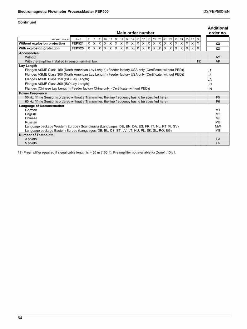
Electromagnetic Flowmeter ProcessMaster FEP500 DS/FEP500-EN
64
Continued
Main order number Additional
order no. Version number 1 – 6 7 8 9 10 11 12 13 14 15 16 17 18 19 20 21 22 23 24 25 26 27
Without explosion protection FEP521 X X X X X X X X X X X X X X X X X X X X X XX With explosion protection FEP525 X X X X X X X X X X X X X X X X X X X X X XX Accessories
Without AY With pre-amplifier installed in sensor terminal box 19) AP
Lay Length Flanges ASME Class 150 (North American Lay Length) (Feeder factory USA only (Certificate: without PED)) J1 Flanges ASME Class 300 (North American Lay Length) (Feeder factory USA only (Certificate: without PED)) J3 Flanges ASME Class 150 (ISO Lay Length) JA Flanges ASME Class 300 (ISO Lay Length) JC Flanges (Chinese Lay Length) (Feeder factory China only (Certificate: without PED)) JN
Power Frequency 50 Hz (If the Sensor is ordered without a Transmitter, the line frequency has to be specified here) F5 60 Hz (If the Sensor is ordered without a Transmitter, the line frequency has to be specified here) F6
Language of Documentation German M1 English M5 Chinese M6 Russian MB Language package Western Europe / Scandinavia (Languages: DE, EN, DA, ES, FR, IT, NL, PT, FI, SV) MW Language package Eastern Europe (Languages: DE, EL, CS, ET, LV, LT, HU, PL, SK, SL, RO, BG) ME
Number of Testpoints 3 points P3 5 points P5
19) Preamplifier required if signal cable length is > 50 m (160 ft). Preamplifier not available for Zone1 / Div1.

Electromagnetic Flowmeter ProcessMaster FEP500 DS/FEP500-EN
65
10.3 FET521, FET525 external transmitter for ProcessMaster
Main order number
Additional order no.
Version number 1 – 6 7 8 9 10 11 12 13 14 15 X
Without explosion protection FET521 X X X X X X X X X X With explosion protection FET525 X X X X X X X X X Temperature Range of Installation / Ambient Temperature Range
Standard design / -20 ... 60 °C (-4 ... 140 °F) 1 Standard design / -40 ... 60 °C (-40 ... 140 °F) 2 High temperature design / -20 ... 60 °C (-4 ... 140 °F) 3 High temperature design / -40 ... 60 °C (-40 ... 140 °F) 4
Name Plate Adhesive label A Stainless steel B Stainless steel and TAG plate (stainless steel) C
Signal Cable Length and Type Without signal cable 1) 0
Explosion Protection Certification Without A ATEX / IEC Zone 1 2) L ATEX / IEC Zone 2 / 21 2) M usFMc Div 2 Zone 2 2) P usFMc Div 1 2) R
Protection Class Transmitter / Protection Class Sensor IP 67 (NEMA 4X) / IP 67 (NEMA 4X) 1
Cable Conduits M20 x 1.5 A 1/2 in. NPT B PF 1/2 in. C
Power Supply 100 ... 230 V AC, 50 Hz 1 24 V AC / DC, 50 Hz 2 100 ... 230 V AC, 60 Hz 3 24 V AC / DC, 60 Hz 4
Input and Output Signal Type HART + 20 mA passive + Pulse + Contact I/O 3) B HART + 20 mA active + Pulse + Contact I/O 4) C HART + 20 mA active + Pulse + Contact Output 5) D PROFIBUS PA + contact output E FOUNDATION Fieldbus + contact output F
Configuration Type / Diagnostics Type Without / standard diagnostic functions 6) 0 Parameters set to factory defaults / Extended diagnostic functions activated 2 Parameters set customer specific / Extended diagnostic functions activated 4
Other Usage Certifications PMO approval (US market only) CR
Connector Fieldbus M12 x 1 7) U2
Other Options With Gore-tex membrane 8) KG
Continued on next page
1) For model FET525 designed for Ex zone 1 / Div 1, 10 m (32.81 ft) of cable is connected to the transmitter. 2) Model FET525 only. 3) Choice with design Zone 2 / Div 2 or Zone 1 / Div1 or Zone 1 / Div1 or without explosion protection. 4) Choice with design Zone 2 / Div 2 or without explosion protection. 5) Choice with design Zone 1 / Div 1. 6) Must be selected if transmitter is being ordered as a spare part or without a sensor. 7) Only for Profibus PA, not for model FET525. 8) Model FET521 only.

Electromagnetic Flowmeter ProcessMaster FEP500 DS/FEP500-EN
66
Continued
Main order number Additional
order no. Version number 1 – 6 7 8 9 10 11 12 13 14 15 X
Without explosion protection FET521 X X X X X X X X X XX With explosion protection FET525 X X X X X X X X X XX Language of Documentation
German M1 English M5 Chinese M6 Russian MB Language package Western Europe / Scandinavia (Languages: DE, EN, DA, ES, FR, IT, NL, PT, FI, SV) MW Language package Eastern Europe (Languages: DE, EL, CS, ET, LV, LT, HU, PL, SK, SL, RO, BG) ME

Electromagnetic Flowmeter ProcessMaster FEP500 DS/FEP500-EN
67
10.4 FET501 transmitter plug-in module for ProcessMaster/HygienicMaster
Main order number
Additional order no.
Version number 1 – 6 7 8 9 10 11 12 13 14 15 X
FET501 X X X X X X X X X X Temperature Range of Installation / Ambient Temperature Range
Standard design / -20 ... 60 °C (-4 ... 140 °F) 1 Name Plate
Adhesive label A Signal Cable Length and Type
Without signal cable 0 Explosion Protection Certification
Without A Protection Class Transmitter / Protection Class Sensor
Others 9 Cable Conduits
Others Z Power Supply
100 ... 230 V AC, 50 Hz 1 24 V AC / DC, 50 Hz 2 100 ... 230 V AC, 60 Hz 3 24 V AC / DC, 60 Hz 4
Input and Output Signal Type HART + 20 mA passive + Pulse + Contact I/O B HART + 20 mA active + Pulse + Contact I/O C PROFIBUS PA + contact output E FOUNDA FOUNDATION Fieldbus + contact output F
Configuration Type / Diagnostics Type Without / Standard diagnostic functions 0
Language of Documentation German M1 English M5 Chinese M6 Russian MB Language package Western Europe / Scandinavia (Languages: DE, EN, DA, ES, FR, IT, NL, PT, FI, SV) MW Language package Eastern Europe (Languages: DE, EL, CS, ET, LV, LT, HU, PL, SK, SL, RO, BG) ME
10.5 FXC4000 flowmeter sensor simulator
Main order number
Version number 1 – 5 6 7 8 9 10
55XC4 X X X X X Flow Signal Setting
Without (adapter only) 0 3-position digitswitch with 1000 steps 1
Power Supply Without (adapter only) 0 110 ... 240 V AC 50 / 60 Hz // With Schuko plug 1 24 ... 48 V AC / DC // With 4 mm plug 2 110 ... 240 V AC 50 / 60 Hz // With US plug 3
Accessories Without 0 Adapter for converter type FXE4000-E4, FXM2000-XM2, FXF2000-DF23 1 Adapter board for converter type FSM4000-S4 5 Adapter board for converter type FET321, FET325, FET521, FET525 6
Design level (specified by ABB) * Name Plate
German 1 English 2 French 3
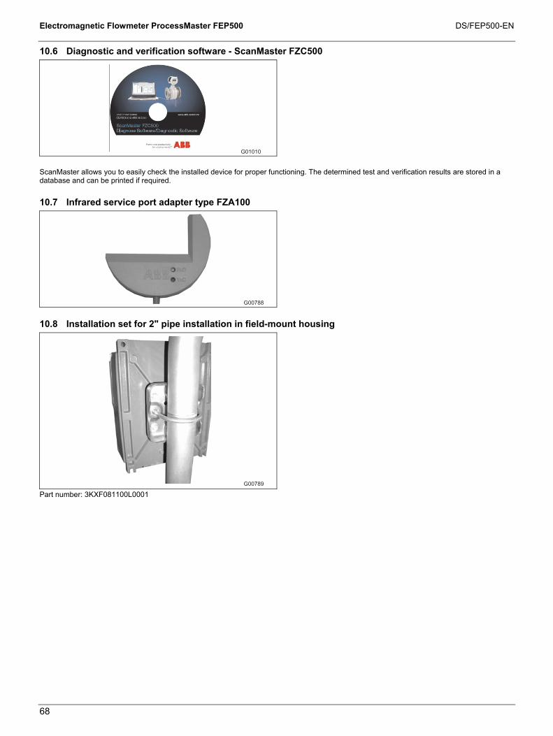
Electromagnetic Flowmeter ProcessMaster FEP500 DS/FEP500-EN
68
10.6 Diagnostic and verification software - ScanMaster FZC500
G01010
ScanMaster allows you to easily check the installed device for proper functioning. The determined test and verification results are stored in a database and can be printed if required.
10.7 Infrared service port adapter type FZA100
G00788
10.8 Installation set for 2" pipe installation in field-mount housing
G00789
Part number: 3KXF081100L0001


Contact us
DS
/FEP
500-
EN12
.201
0|
3KXF
2315
00R
1001ABB Ltd.
Oldends Lane, Stonehouse Gloucestershire, GL10 3TA UK Phone: +44 (0)1453 826661 Fax: +44 (0)1453 829671 ABB Inc. 125 E. County Line Road Warminster PA 18974 USA Phone: +1 215 674 6000 Fax: +1 215 674 7183 ABB Automation Products GmbH Dransfelder Str. 2 37079 Goettingen Germany Phone: +49 551 905-534 Fax: +49 551 905-555 www.abb.com
Note We reserve the right to make technical changes or modify the contents of this document without prior notice. With regard to purchase orders, the agreed particulars shall prevail. ABB does not accept any responsibility whatsoever for potential errors or possible lack of information in this document. We reserve all rights in this document and in the subject matter and illustrations contained therein. Any reproduction, disclosure to third parties or utilization of its contents - in whole or in parts – is forbidden without prior written consent of ABB. Copyright© 2010 ABB All rights reserved