product and technical manual - autospec media...
TRANSCRIPT

PRODUCT AND TECHNICAL MANUALAdhering to the use of good roofing practices
Part of the MONIER GROUP
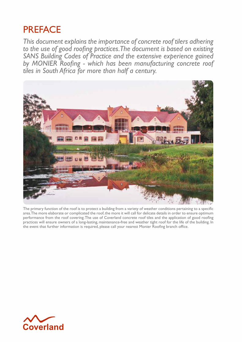
PREFACEThis document explains the importance of concrete roof tilers adhering to the use of good roofing practices. The document is based on existing SANS Building Codes of Practice and the extensive experience gained by MONIER Roofing - which has been manufacturing concrete roof tiles in South Africa for more than half a century.
The primary function of the roof is to protect a building from a variety of weather conditions pertaining to a specific area. The more elaborate or complicated the roof, the more it will call for delicate details in order to ensure optimum performance from the roof covering. The use of Coverland concrete roof tiles and the application of good roofing practices will ensure owners of a long-lasting, maintenance-free and weather tight roof for the life of the building. In the event that further information is required, please call your nearest Monier Roofing branch office.

1
CONCRETE ROOF TILE RANGE
2 Double Roman
3 Taunus
4 Renown
5 Cupola
6 Elite
7 Perspective
8 Lumino Tile Finish
9 Fittings - Concrete Roof Tiles
10 Arkitone Range
CLAY ROOF TILE RANGE
11 Cotto Coperture Range
12 Marseille Range
13 Occitane Range
WORLD OF ROOFING SYSTEM COMPONENTS
14-19 Roofing Components Range
20 Cool Roof System
21 Dry Ridge System
TECHNICAL GUIDELINES
22 Fixing the Undertile Membrane and Battens
23 Windloading and Undertile Membranes
23 Batten Centres
24 Inspecting the Roof Structure
25 Cutting and Drilling of Tiles
26 Tiling
GENERAL SUPPORT INFORMATION
27 Efflorescence
27 Mortar Bedding
28 Rake Verge
29 Abutments
30 Roof Tile Estimating
32 Laying and Fixing Specifications
34 Physical and Chemical Properties
35 Hailstones
36 10 Easy Steps to Tiling a Roof
41 Roof Structure Terminology
INDEX
2
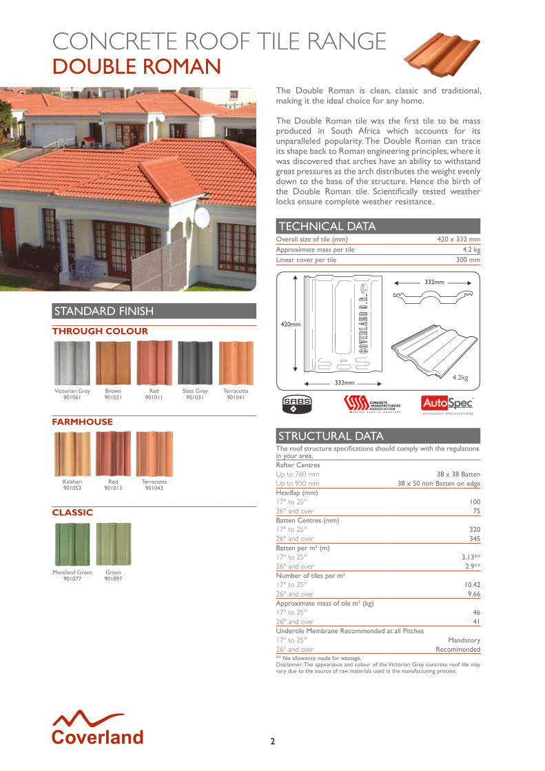
DOUBLE ROMANCONCRETE ROOF TILE RANGE
The Double Roman is clean, classic and traditional, making it the ideal choice for any home.
The Double Roman tile was the first tile to be mass produced in South Africa which accounts for its unparalleled popularity. The Double Roman can trace its shape back to Roman engineering principles, where it was discovered that arches have an ability to withstand great pressures as the arch distributes the weight evenly down to the base of the structure. Hence the birth of the Double Roman tile. Scientifically tested weather locks ensure complete weather resistance.
TECHNICAL DATAOverall size of tile (mm) 420 x 332 mmApproximate mass per tile 4.2 kgLinear cover per tile 300 mm
STRUCTURAL DATAThe roof structure specifications should comply with the regulations in your area.Rafter CentresUp to 760 mm 38 x 38 BattenUp to 950 mm 38 x 50 mm Batten on edgeHeadlap (mm)17° to 25° 10026° and over 75Batten Centres (mm)17° to 25° 32026° and over 345Batten per m² (m)17° to 25° 3.13**26° and over 2.9**Number of tiles per m²17° to 25° 10.4226° and over 9.66Approximate mass of tile m² (kg)17° to 25° 4626° and over 41Undertile Membrane Recommended at all Pitches17° to 25° Mandatory26° and over Recommended** No allowance made for wastage.Disclaimer: The appearance and colour of the Victorian Grey concrete roof tile may vary due to the source of raw materials used in the manufacturing process.
STANDARD FINISH
THROUGH COLOUR
Victorian Grey901061
Brown901021
Red901011
Slate Grey901031
Terracotta901041
FARMHOUSE
Kalahari901053
Red901013
Terracotta901043
CLASSIC
Moreland Green901077
Green901097
332mm
420mm
332mm4.2kg

3
Always eager to set new standards in style, quality and excellence, MONIER Roofing developed the striking Taunus. This bold profile tile has a long and noble history. For centuries they were individually handmade from clay.
Not only does it represent the highest standards in technical refinement, but now, thanks to MONIER Roofing’s unique production capability, the Taunus is stronger, more balanced and above all, more affordable than its predecessor.
Taunus boasts a required incline of 17°, making it the perfect choice for low-pitched roofs. It’s deep roll creates roofs of majestic character with it’s bold, striking contours and organic undulating rolls.
TECHNICAL DATAOverall size of tile (mm) 420 x 332 mmApproximate mass per tile 4.4 kgLinear cover per tile 300 mm
STRUCTURAL DATAThe roof structure specifications should comply with the regulations in your area.Rafter CentresUp to 760 mm 38 x 38 BattenUp to 950 mm 38 x 50 mm Batten on edgeHeadlap (mm)17° to 25° 10026° and over 75Batten Centres (mm)17° to 25° 32026° and over 345Batten per m² (m)17° to 25° 3.13**26° and over 2.9**Number of tiles per m²17° to 25° 10.4226° and over 9.66Approximate mass of tile m² (kg)17° to 25° 4626° and over 43Undertile Membrane Recommended at all Pitches17° to 25° Mandatory26° and over Recommended** No allowance made for wastage.Disclaimer: The printing process, age and lighting conditions may affect the appearance and colour of these illustrations. MONIER Roofing recommends you examine an actual sample tile of your colour choice before making your buying decision. Special colours are available on request. Contact your nearest outlet for further information.
4.4kg
332mm
332mm
420mm
TAUNUS
STANDARD FINISH
THROUGH COLOUR
Brown910021
Kalahari910051
Red910011
Slate Grey910031
Terracotta910041
FARMHOUSE
Brown910023
Kalahari910053
Red910013
Terracotta910043
LUMINO CRYSTAL FINISH
FARMHOUSE
Brown910023/3
Kalahari910053/3
Red910013/3
Terracotta910043/3
LUMINO FLAIR FINISH
THROUGH COLOUR
Black910031/4
Green910091/4
White910081/4
nEW
nEW

4
STANDARD FINISH
THROUGH COLOUR
Red906011
Slate Grey906031
Terracotta906041
LUMINO FLAIR FINISH
THROUGH COLOUR
Black*906031/4
Green*906091/4
RENOWNThe Renown tile is incredibly sturdy in appearance and composition. This profile boasts an extremely efficient weather lock.
The Renown is a distinct concrete roof tile with a subtle geometric shape. Its heritage is traditionally European in origin and could even be traced back to Roman times.
The Renown is a tile that speaks for itself through its clean sophisticated lines and elegantly chiselled profile, yet engineered to be cost-effective and durable.
TECHNICAL DATAOverall size of tile (mm) 420 x 332 mmApproximate mass per tile 4.4 kgLinear cover per tile 300 mm
STRUCTURAL DATAThe roof structure specifications should comply with the regulations in your area.Rafter CentresUp to 760 mm 38 x 38 BattenUp to 950 mm 38 x 50 mm Batten on edgeHeadlap (mm)17° to 25° 10026° and over 75Batten Centres (mm)17° to 25° 32026° and over 345Batten per m² (m)17° to 25° 3.13**26° and over 2.9**Number of tiles per m²17° to 25° 10.4226° and over 9.66Approximate mass of tile m² (kg)17° to 25° 4626° and over 43Undertile Membrane Recommended at all Pitches17° to 25° Mandatory26° and over Recommended** No allowance made for wastage. * Only available in KwaZulu-Natal and Free State.Disclaimer: The printing process, age and lighting conditions may affect the appearance and colour of these illustrations. MONIER Roofing recommends you examine an actual sample tile of your colour choice before making your buying decision. Special colours are available on request. Contact your nearest outlet for further information.
4.4kg
420mm
330mm
330mm
nEW
5
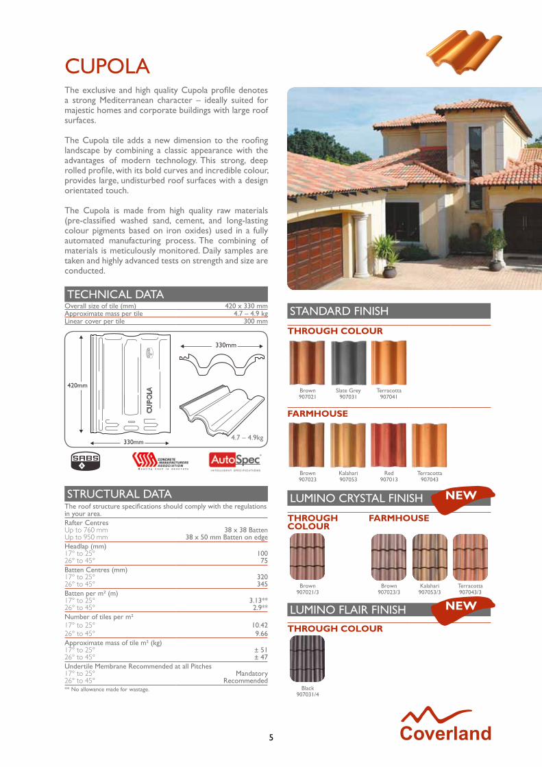
The exclusive and high quality Cupola profile denotes a strong Mediterranean character – ideally suited for majestic homes and corporate buildings with large roof surfaces.
The Cupola tile adds a new dimension to the roofing landscape by combining a classic appearance with the advantages of modern technology. This strong, deep rolled profile, with its bold curves and incredible colour, provides large, undisturbed roof surfaces with a design orientated touch.
The Cupola is made from high quality raw materials (pre-classified washed sand, cement, and long-lasting colour pigments based on iron oxides) used in a fully automated manufacturing process. The combining of materials is meticulously monitored. Daily samples are taken and highly advanced tests on strength and size are conducted.
TECHNICAL DATAOverall size of tile (mm) 420 x 330 mmApproximate mass per tile 4.7 – 4.9 kgLinear cover per tile 300 mm
STRUCTURAL DATAThe roof structure specifications should comply with the regulations in your area.Rafter CentresUp to 760 mm 38 x 38 BattenUp to 950 mm 38 x 50 mm Batten on edgeHeadlap (mm)17° to 25° 10026° to 45° 75Batten Centres (mm)17° to 25° 32026° to 45° 345Batten per m² (m)17° to 25° 3.13**26° to 45° 2.9**Number of tiles per m²17° to 25° 10.4226° to 45° 9.66Approximate mass of tile m² (kg)17° to 25° ± 5126° to 45° ± 47Undertile Membrane Recommended at all Pitches17° to 25° Mandatory26° to 45° Recommended** No allowance made for wastage.
4.7 – 4.9kg
330mm
420mm
330mm
CUPOLA
STANDARD FINISH
THROUGH COLOUR
Brown907021
Slate Grey907031
Terracotta907041
FARMHOUSE
Brown907023
Kalahari907053
Red907013
Terracotta907043
LUMINO CRYSTAL FINISH
THROUGHCOLOUR
FARMHOUSE
Brown907021/3
Brown907023/3
Kalahari907053/3
Terracotta907043/3
LUMINO FLAIR FINISH
THROUGH COLOUR
Black907031/4
nEW
nEW
6
STANDARD FINISH
THROUGH COLOUR
Black905031
LUMINO FLAIR FINISH
THROUGH COLOUR
Black905031/4
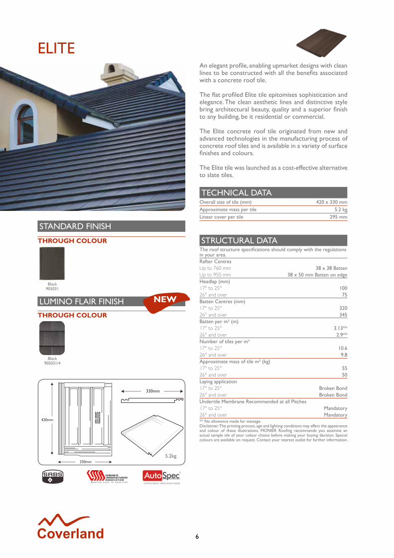
ELITEAn elegant profile, enabling upmarket designs with clean lines to be constructed with all the benefits associated with a concrete roof tile.
The flat profiled Elite tile epitomises sophistication and elegance. The clean aesthetic lines and distinctive style bring architectural beauty, quality and a superior finish to any building, be it residential or commercial.
The Elite concrete roof tile originated from new and advanced technologies in the manufacturing process of concrete roof tiles and is available in a variety of surface finishes and colours.
The Elite tile was launched as a cost-effective alternative to slate tiles.
TECHNICAL DATAOverall size of tile (mm) 420 x 330 mmApproximate mass per tile 5.2 kgLinear cover per tile 295 mm
STRUCTURAL DATAThe roof structure specifications should comply with the regulations in your area.Rafter CentresUp to 760 mm 38 x 38 BattenUp to 950 mm 38 x 50 mm Batten on edgeHeadlap (mm)17° to 25° 10026° and over 75Batten Centres (mm)17° to 25° 32026° and over 345Batten per m² (m)17° to 25° 3.13**26° and over 2.9**Number of tiles per m²17° to 25° 10.626° and over 9.8Approximate mass of tile m² (kg)17° to 25° 5526° and over 50Laying application17° to 25° Broken Bond26° and over Broken BondUndertile Membrane Recommended at all Pitches17° to 25° Mandatory26° and over Mandatory** No allowance made for wastage.Disclaimer: The printing process, age and lighting conditions may affect the appearance and colour of these illustrations. MONIER Roofing recommends you examine an actual sample tile of your colour choice before making your buying decision. Special colours are available on request. Contact your nearest outlet for further information.
5.2kg
330mm
420mm
330mm
nEW
7
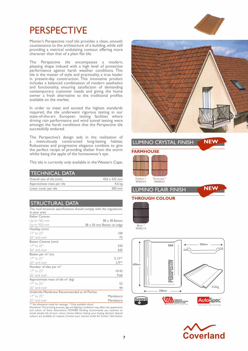
PERSPECTIVEMonier’s Perspective roof tile provides a clean, smooth countenance to the architecture of a building, while still providing a metrical undulating contour, offering more character than that of a plain flat tile.
The Perspective tile encompasses a modern, pleasing shape imbued with a high level of protective performance against harsh weather conditions. This tile is the master of style and practicality, a true leader in present-day construction. This innovative product includes a balanced combination of modern aesthetics and functionality, ensuring satisfaction of demanding contemporary customer needs and giving the home owner a fresh alternative to the traditional profiles available on the market.
In order to meet and exceed the highest standards required, the tile underwent rigorous testing in our state-of-the-art European testing facilities where driving rain performance and wind tunnel testing were amongst the harsh conditions that the Perspective tile successfully endured. The Perspective’s design aids in the realisation of a meticulously constructed long-lasting habitat. Robustness and progressive elegance combine to give the perfect recipe of providing shelter from the storm whilst being the apple of the homeowner’s eye.
This tile is currently only available in the Western Cape.
TECHNICAL DATAOverall size of tile (mm) 420 x 332 mmApproximate mass per tile 4.6 kgLinear cover per tile 300 mm
STRUCTURAL DATAThe roof structure specifications should comply with the regulations in your area.Rafter CentresUp to 760 mm 38 x 38 BattenUp to 950 mm 38 x 50 mm Batten on edgeHeadlap (mm)17° to 25° 10026° and over 75Batten Centres (mm)17° to 25° 32026° and over 345Batten per m² (m)17° to 25° 3.13**26° and over 2.9**Number of tiles per m²17° to 25° 10.4226° and over 9.66Approximate mass of tile m² (kg)17° to 25° 5226° and over 44Undertile Membrane Recommended at all Pitches17° to 25° Mandatory26° and over Mandatory** No allowance made for wastage. * Only available inland.Disclaimer: The printing process, age and lighting conditions may affect the appearance and colour of these illustrations. MONIER Roofing recommends you examine an actual sample tile of your colour choice before making your buying decision. Special colours are available on request. Contact your nearest outlet for further information.
LUMINO CRYSTAL FINISH
FARMHOUSE
Kalahari *904053/3
Terracotta *904043/3
LUMINO FLAIR FINISH
THROUGH COLOUR
Black *904031/4
nEW
nEW
4.6kg
420mm
330mm
330mm
8
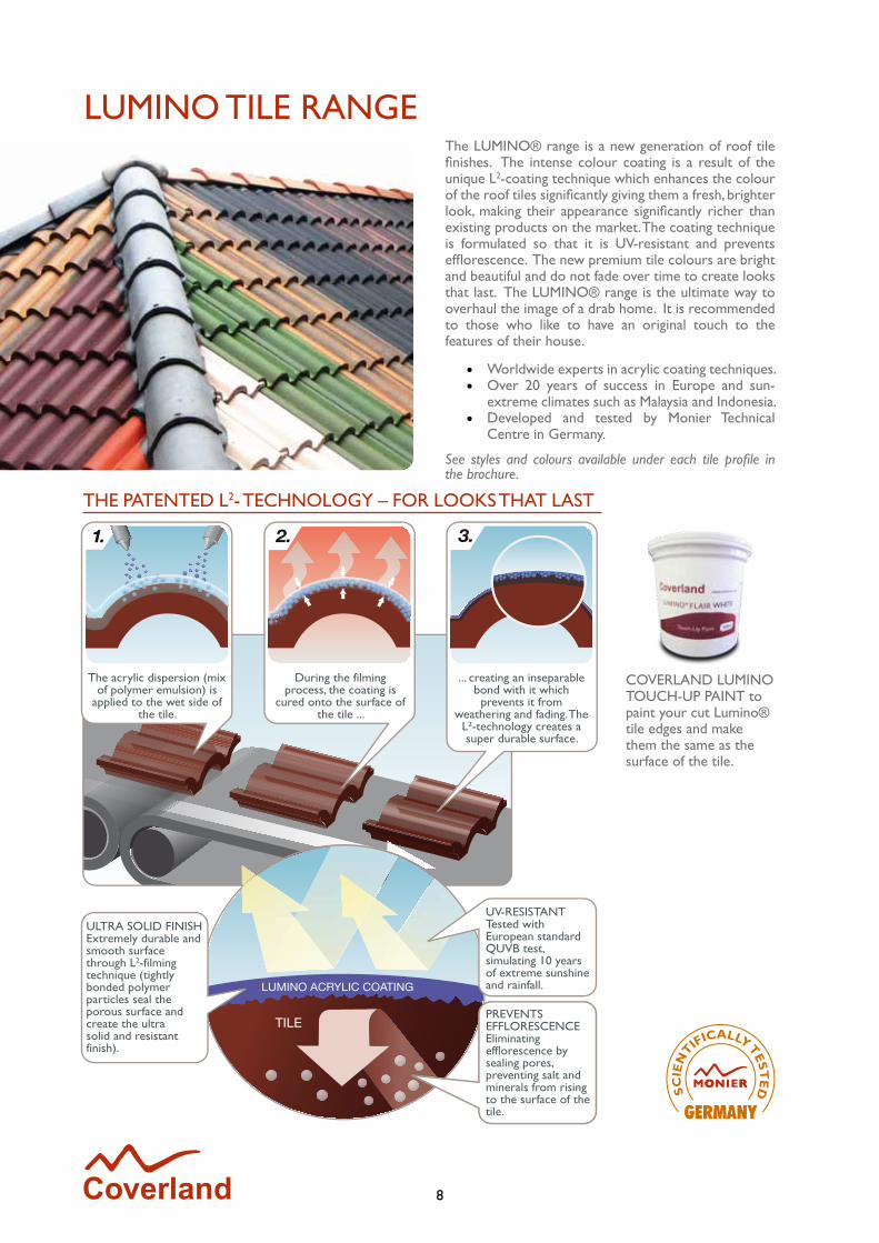
LUMINO TILE RANGEThe LUMINO® range is a new generation of roof tile finishes. The intense colour coating is a result of the unique L2-coating technique which enhances the colour of the roof tiles significantly giving them a fresh, brighter look, making their appearance significantly richer than existing products on the market. The coating technique is formulated so that it is UV-resistant and prevents efflorescence. The new premium tile colours are bright and beautiful and do not fade over time to create looks that last. The LUMINO® range is the ultimate way to overhaul the image of a drab home. It is recommended to those who like to have an original touch to the features of their house.
• Worldwide experts in acrylic coating techniques.• Over 20 years of success in Europe and sun-
extreme climates such as Malaysia and Indonesia.• Developed and tested by Monier Technical
Centre in Germany.
See styles and colours available under each tile profile in the brochure.
COVERLAND LUMINO TOUCH-UP PAINT to paint your cut Lumino® tile edges and make them the same as the surface of the tile.
THE PATENTED L2- TECHNOLOGY – FOR LOOKS THAT LAST
During the filming process,the coating is cured onto thesurface of the tile ...
... creating an inseparable bondwith it which prevents it fromweathering and fading. The L2technology creates a super durable surface.
The acrylic dispersion (mix of polymer emulsion) is
applied to the wet side of the tile.
During the filming process, the coating is
cured onto the surface of the tile ...
... creating an inseparable bond with it which prevents it from
weathering and fading. The L²-technology creates a super durable surface.
ULTRA SOLID FINISHExtremely durable and smooth surfacethrough L2-filming technique (tightlybonded polymer particles seal theporous surface and create the ultrasolid and resistant finish).
UV-RESISTANTTested with European standardQUVB test, simulating 10 yearsof extreme sunshine and rainfall.
PREVENTS EFFLORESCENCEEliminating efflorescence by sealing pores, preventing salt and minerals from rising to the surface of the tile. GERMANY

9
FITTINGS – CONCRETE ROOF TILES“V” RIDGE HIP STARTERNo. per Hip One Fixing Bed in mortar. CoverlandThickness 14-16 mm Dry Ridge System included
Laying Open end butts next tileMass ± 4.4 kg
“V” RIDGE TILENo. per LM ± 2.2 tiles Fixing Bed in mortar. CoverlandThickness 12-14 mm Dry Ridge System included
Laying Butt jointedMass ± 3.7 kg (Standard)
TAPERED HIP STARTERNo. per Hip One Fixing Bed in mortar. CoverlandThickness 13-16 mm Dry Ridge System included
Laying OverlappingMass ± 4.4 kg
TAPERED RIDGENo. per LM ± 2.5 tiles Fixing Bed in mortar. CoverlandThickness 13-16 mm Dry Ridge System included
Laying OverlappingMass ± 4.2 kg
“V” VENT RIDGENo. per LM ± 2.2 tiles Fixing Bed in mortar. CoverlandThickness 12-14 mm Dry Ridge System included
Laying Butt jointedMass ± 8 kg
MONO RIDGENo. per LM ± 2.2 tiles Fixing Bed in mortar. CoverlandThickness 14-16 mm Dry Ridge System included
Laying Butt jointedMass ± 5 kg (Standard)
TAPERED VENT RIDGENo. per LM ± 2.5 tiles Fixing Bed in mortar. CoverlandThickness 13-16 mm Dry Ridge System included
Laying OverlappingMass ± 7 kg
RAKE VERGENo. per Verge One per tile
course + one
Fixing Two non-corrodible screws or nails
Thickness 14-16 mm Laying OverlappingMass ± 5.4 kg (Standard)

10
STANDARD FINISH
TAUnUS & CUpOLA
Autumn Sunset Tuscan Dusk Harvester
LUMINO CRYSTAL FINISH
TAUnUS CUpOLA
Tuscan Mix Tuscan Mix
ARKITONE RANGEThe Arkitone Range is a Mediterranean concept of randomly laid concrete roof tiles of different colours creating an artistic style in roofing. It makes a quiet statement in superiority, status and appearance. Definitely in a class of its own!
A N E X P R E S S I O N O F C R E A T I V I T Y
nEW

11
The undulating shape and the geometric form of the Cotto Coperture clay tile is recognised by the bold roll and special overlapping side and back grooves. This ensures that rain water, hail and snow slides freely and fast from the roof. The Cotto Coperture range offers excellent features such as weather resistant, durability and watertightness. The Cotto Coperture clay tile range consists of the Cotto Coperture Dorotea and Cotto Coperture Red Argilla, which are fully imported from Italy.
STRUCTURAL DATATile Size 415 x 255 mm
Linear Cover (width) 200 mm
Number of tiles per m² 14.4
Batten Centres (mm)* 345 mm
Weight per tile 2.9 kg
Weight per m² 14.76 kg
Laying Application Straight Bond
Minimum Roof Pitch 17.5°
Undertile Membrane Recommended at all pitchesMandatory 17.5° - 25°
* It is advisable to measure approximately 20 tiles on site before battening the roof as tile sizes can vary during the firing of the clay.
RIDGE
No. per LM Size 3.3 tiles Fixing 40.5 - 28 cm Bed in mortarLaying OverlappingMass 3.1 kg
THREE WAY RIDGE
No. per LM Size Where necessary Fixing 44 - 47.5 cm Bed in mortarLaying OverlappingMass 5.2 kg
HIP STARTER
No. per LM Size OneFixing 40.5 - 28 cm Bed in mortarLaying OverlappingMass 3.2 kg
FOUR WAY RIDGE
No. per LM Size Where necessary Fixing 40.5 - 40.5 cm Bed in mortarLaying OverlappingMass 8.6 kg
COTTO COPERTURECLAY ROOF TILE RANGE
DOROTEAEpitomising the perfect balance between the past and the present, the Cotto Coperture Dorotea combines modern technology with the appearance of the ancient Tyrrhenian fascia roofing on the Italian peninsula.
Different colours and shades depict the effects of time and the inclement sun and rain. Over the years, the combination of yellows, reds and browns of varying nuances, create a picturesque mosaic of beautiful harmonising colours.
The colours and shades of ancient times are reflected in the five different surface finishes of the tile. The final effect is that of a roof with warm tones, incorporating different shades of red and yellow, reminiscent of Tyrrhenian roof designs.
RED ARGILLAIn the making of Architectural masterpieces, there is a need for natural substances. One tries to construct a harmony between countryside and architecture, between man’s creation and nature.
The Red Argilla is a natural red clay tile which offers developers, specifiers and homeowners the opportunity to use a clay roof tile to blend in with nature, while achieving the style and tradition of a Mediterranean roof.
COPPO DOMUS RUSTICOCoppo Domus is handmade, handcrafted, one by one, as the ancient roof tiles. The new colours are cleverly inspired by the Italian landscape: its countryside, its medieval villages, its distinctive Mediterranean style.
12
INTERLOCKING HIP TILE 40
No. per LM 2.5 tilesFixing 43.5 - 25 cm Bed in mortar/ Dry Ridge SystemLaying OverlappingMass 3 kg
INTERLOCKING END HIP 40
No. per LM Where necessaryFixing Bed in mortar/ Dry Ridge SystemLaying OverlappingMass 3.3 kg
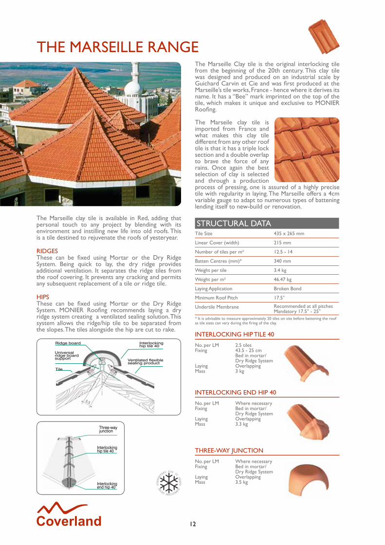
THE MARSEILLE RANGEThe Marseille Clay tile is the original interlocking tile from the beginning of the 20th century. This clay tile was designed and produced on an industrial scale by Guichard Carvin et Cie and was first produced at the Marseille’s tile works, France - hence where it derives its name. It has a “Bee” mark imprinted on the top of the tile, which makes it unique and exclusive to MONIER Roofing.
The Marseile clay tile is imported from France and what makes this clay tile different from any other roof tile is that it has a triple lock section and a double overlap to brave the force of any rains. Once again the best selection of clay is selected and through a production process of pressing, one is assured of a highly precise tile with regularity in laying. The Marseille offers a 4cm variable gauge to adapt to numerous types of battening lending itself to new-build or renovation.
The Marseille clay tile is available in Red, adding that personal touch to any project by blending with its environment and instilling new life into old roofs. This is a tile destined to rejuvenate the roofs of yesteryear.
RIDGESThese can be fixed using Mortar or the Dry Ridge System. Being quick to lay, the dry ridge provides additional ventilation. It separates the ridge tiles from the roof covering. It prevents any cracking and permits any subsequent replacement of a tile or ridge tile.
HIPSThese can be fixed using Mortar or the Dry Ridge System. MONIER Roofing recommends laying a dry ridge system creating a ventilated sealing solution. This system allows the ridge/hip tile to be separated from the slopes. The tiles alongside the hip are cut to rake.
Three-wayjunction
Interlocking hip tile 40
Interlocking end hip 40
STRUCTURAL DATATile Size 435 x 265 mm
Linear Cover (width) 215 mm
Number of tiles per m² 12.5 - 14
Batten Centres (mm)* 340 mm
Weight per tile 3.4 kg
Weight per m² 46.47 kg
Laying Application Broken Bond
Minimum Roof Pitch 17.5°
Undertile Membrane Recommended at all pitchesMandatory 17.5° - 25°
* It is advisable to measure approximately 20 tiles on site before battening the roof as tile sizes can vary during the firing of the clay.
THREE-WAY jUNCTION
No. per LM Where necessaryFixing Bed in mortar/ Dry Ridge SystemLaying OverlappingMass 3.5 kg
Interlocking hip tile 40
Ventilated flexible sealing product
Ridge board
Universal ridge board support
Tile
13
HALF-ROUND RIDGE/HIP TILE 50
No. per LM 2.5 tilesFixing 47 - 24 cm Bed in mortar/ Dry Ridge SystemLaying OverlappingMass 4.3 kg
END HIP TILE 50
No. per LM Where necessaryFixing Bed in mortar/ Dry Ridge SystemLaying OverlappingMass 4.2 kg
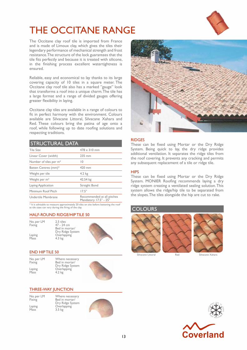
The Occitane clay roof tile is imported from France and is made of Limoux clay, which gives the tiles their legendary performance of mechanical strength and frost resistance. The structure of the lock guarantees that the tile fits perfectly and because it is treated with silicone, in the finishing process excellent watertightness is ensured.
Reliable, easy and economical to lay thanks to its large covering capacity of 10 tiles in a square meter. The Occitane clay roof tile also has a marked ”gauge” look that transforms a roof into a unique charm. The tile has a large format and a range of divided gauges offering greater flexibility in laying.
Occitane clay tiles are available in a range of colours to fit in perfect harmony with the environment. Colours available are Silvacane Littoral, Silvacane Xahara and Red. These colours bring the patina of age onto a roof, while following up to date roofing solutions and respecting traditions.
STRUCTURAL DATATile Size 478 x 310 mm
Linear Cover (width) 235 mm
Number of tiles per m² 10
Batten Centres (mm)* 420 mm
Weight per tile 4.2 kg
Weight per m² 42.54 kg
Laying Application Straight Bond
Minimum Roof Pitch 17.5°
Undertile Membrane Recommended at all pitchesMandatory 17.5° - 25°
* It is advisable to measure approximately 20 tiles on site before battening the roof as tile sizes can vary during the firing of the clay.
THREE-WAY jUNCTION
No. per LM Where necessaryFixing Bed in mortar/ Dry Ridge SystemLaying OverlappingMass 3.5 kg
THE OCCITANE RANGE
COLOURS
Silvacane Littoral Red Silvacane Xahara
RIDGESThese can be fixed using Mortar or the Dry Ridge System. Being quick to lay, the dry ridge provides additional ventilation. It separates the ridge tiles from the roof covering. It prevents any cracking and permits any subsequent replacement of a tile or ridge tile.
HIPSThese can be fixed using Mortar or the Dry Ridge System. MONIER Roofing recommends laying a dry ridge system creating a ventilated sealing solution. This system allows the ridge/hip tile to be separated from the slopes. The tiles alongside the hip are cut to rake.
14
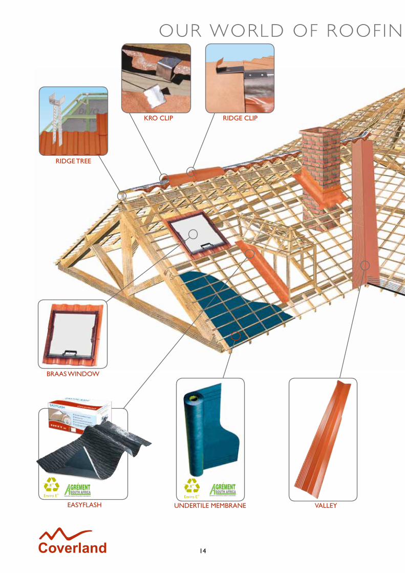
RIDGE TREE
RIDGE CLIP
BRAAS WINDOW
UNDERTILE MEMBRANEEASYFLASH
KRO CLIP
OUR WORLD OF ROOFIN G SYSTEM COMPONENTS
VALLEY
15
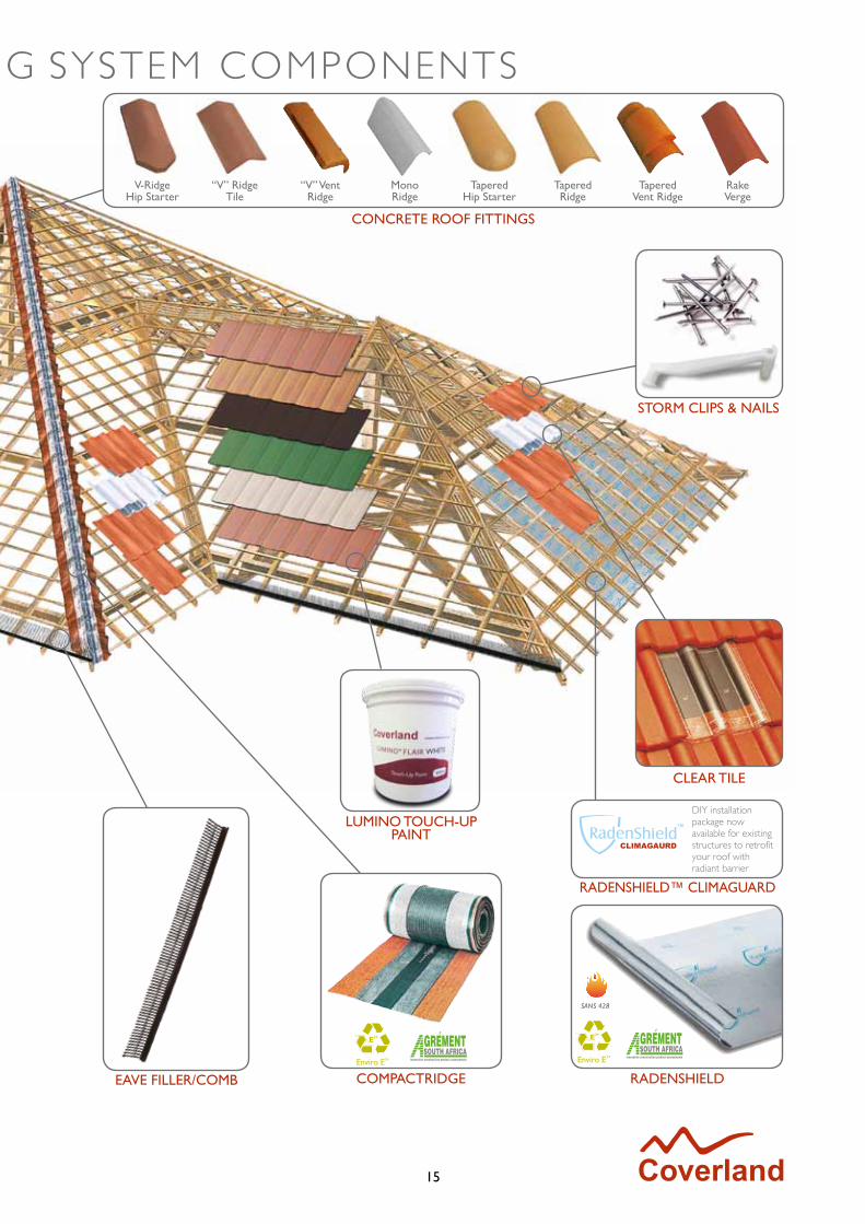
CLEAR TILE
RADENSHIELDCOMPACTRIDGE
LUMINO TOUCH-UP PAINT
STORM CLIPS & NAILS
CONCRETE ROOF FITTINGS
OUR WORLD OF ROOFIN G SYSTEM COMPONENTS
EAVE FILLER/COMB
CLIMAGAURD
RADENSHIELD™ CLIMAGUARD
DIY installation package now available for existing structures to retrofit your roof with radiant barrier
V-RidgeHip Starter
“V” RidgeTile
“V” VentRidge
MonoRidge
TaperedHip Starter
TaperedRidge
TaperedVent Ridge
RakeVerge
16
COMPACTRIDGEThe only ventilating ridge system that prevents leaks and is maintenance-free.
Features and Benefits• The most storm-proof solution on the South
African market• Prevents mould by allowing ventilation (mould
affects your health and the health of your roof)• Compared over 1- 3 years, CompactRidge has
a material and labour cost-saving of 28% to 133% compared to traditional mortar products
• No cracking or leaking normally attributed to mortar applications
• Maintenance-free• Time saving: installed in one third of the time
compared to traditional methods
Technical Data• Material: Aluminium, polyisobutylen and fleece• Ventilation cross-section: 170 cm2/m• Packaging units: 10m rolls
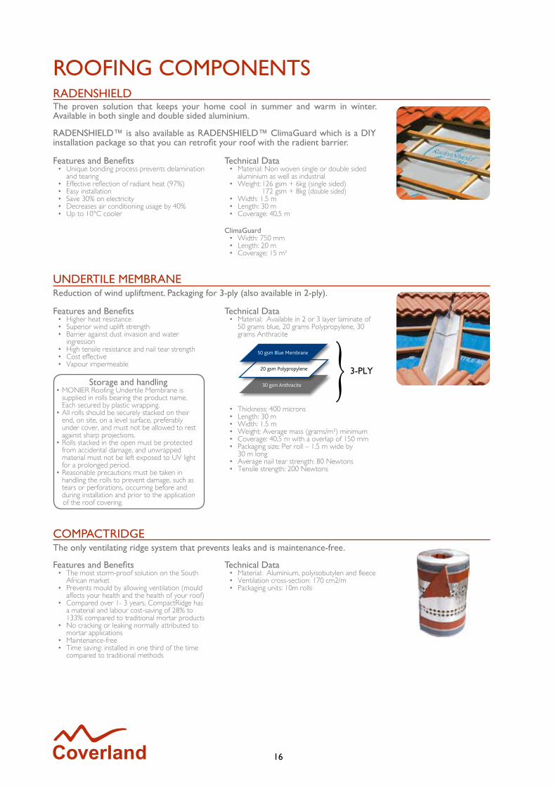
Features and Benefits• Higher heat resistance• Superior wind uplift strength• Barrier against dust invasion and water
ingression• High tensile resistance and nail tear strength• Cost effective• Vapour impermeable
Technical Data• Material: Available in 2 or 3 layer laminate of
50 grams blue, 20 grams Polypropylene, 30 grams Anthracite
• Thickness: 400 microns• Length: 30 m • Width: 1.5 m• Weight: Average mass (grams/m²) minimum• Coverage: 40,5 m with a overlap of 150 mm• Packaging size: Per roll – 1.5 m wide by
30 m long• Average nail tear strength: 80 Newtons• Tensile strength: 200 Newtons
Storage and handling• MONIER Roofing Undertile Membrane is
supplied in rolls bearing the product name. Each secured by plastic wrapping.
• All rolls should be securely stacked on their end, on site, on a level surface, preferably under cover, and must not be allowed to rest against sharp projections.
• Rolls stacked in the open must be protected from accidental damage, and unwrapped material must not be left exposed to UV light for a prolonged period.
• Reasonable precautions must be taken in handling the rolls to prevent damage, such as tears or perforations, occurring before and during installation and prior to the application of the roof covering.
UNDERTILE MEMBRANEReduction of wind upliftment. Packaging for 3-ply (also available in 2-ply).
RADENSHIELDThe proven solution that keeps your home cool in summer and warm in winter. Available in both single and double sided aluminium.
RADENSHIELD™ is also available as RADENSHIELD™ ClimaGuard which is a DIY installation package so that you can retrofit your roof with the radient barrier.
Features and Benefits• Unique bonding process prevents delamination
and tearing • Effective reflection of radiant heat (97%) • Easy installation • Save 30% on electricity • Decreases air conditioning usage by 40% • Up to 10°C cooler
Technical Data• Material: Non woven single or double sided
aluminium as well as industrial • Weight: 126 gsm + 6kg (single sided)
172 gsm + 8kg (double sided)• Width: 1.5 m• Length: 30 m• Coverage: 40,5 m
ClimaGuard• Width: 750 mm• Length: 20 m• Coverage: 15 m²
ROOFING COMPONENTS
17
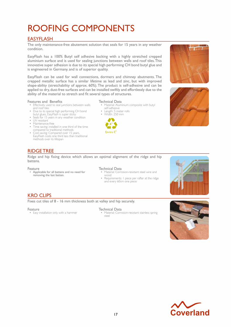
EASYFLASHThe only maintenance-free abutement solution that seals for 15 years in any weather condition.
EasyFlash has a 100% Butyl self adhesive backing with a highly stretched crepped aluminium surface and is used for sealing junctions between walls and roof tiles. This innovative super adhesion is due to its special high performing CH bond butyl glue and is engineered in Germany. and is of superior quality.
EasyFlash can be used for wall connections, dormers and chimney abutments. The crepped metallic surface has a similar lifetime as lead and zinc, but with improved shape-ability (stretchability of approx. 60%). The product is self-adhesive and can be applied to dry, dust-free surfaces and can be installed swiftly and effortlessly due to the ability of the material to stretch and fit several types of structures.
Features and Benefits• Effectively used to seal junctions between walls
and roof tiles • Due to its special high performing CH bond
butyl glues, EasyFlash is super sticky• Seals for 15 years in any weather condition • UV resistant • Maintenance-free • Time saving: installed in one third of the time
compared to traditional methods • Cost-saving: Compared over 15 years,
EasyFlash costs one third less than traditional methods over its lifespan
Technical Data• Material: Aluminium composite with butyl
self-adhesive• Length: 5 meter rolls• Width: 250 mm
KRO CLIPSFixes cut tiles of 8 - 16 mm thickness both at valley and hip securely.
Feature• Easy installation only with a hammer
Technical Data• Material: Corrosion-resistant stainless spring
steel
RIDGE TREERidge and hip fixing device which allows an optimal alignment of the ridge and hip battens.
Feature• Applicable for all battens and no need for
removing the last batten.
Technical Data• Material: Corrosion-resistant steel wire and
wood• Requirements: 1 piece per rafter at the ridge
and every 60cm one piece
ROOFING COMPONENTS

18
ROOFING COMPONENTS
VALLEYSThese pre-cut, pre-shaped solution for valleys are of a high quality, and are highly durable, they are quick and easy to install as no preparation of the valley is required.
Features and Benefits• No under-construction required• Little installation time and durable• No fixing clips required• Low price• High performance
Technical Data• Material: Aluminium base metal sheet valley
Hot dip galvanised steel (PUR coating Ragal 320 GD + Z 275 *Pural*)
• Size: 2100 mm x 460 mm• Colours: Brown, Black, Terracotta
CLEAR TILEThe Clear Tile has been designed as a cost-effective means of illuminating rooms and is easy to install. It is a profile that has been constructed out of extremely durable, highly transparent polycarbonate acrylic. The Clear Tile has the same dimensions as those of the standard profiles and is available in the Coverland profiles - Cupola, Double Roman and Taunus.
This product has been produced to withstand the harshest elements for a prolonged period of time, is resistant to ultraviolet rays and will provide many years of trouble-free illumination.
Features and Benefits• Simple to install, (takes the place of the
existing concrete roof tile).• Each tile is fitted with a securing device for
proper installation • Allows light to enter the roof space
illuminating room surroundings, including garages, attics, atriums.
• Produced to withstand the harshest elements (wind tunnel tested - Germany).
• Highly UV resistant and aesthetically distinctive. (UV simulation tested - Germany).
Technical Data• Material: Transparent Polycarbonate –
extremely durable
Installation• The Clear tile is easy to install as it simply takes
the place of the existing concrete roof tile.• Each tile is fitted with a securing device for
proper installation
EAVES FILLERPrevents the access of birds and mice, and facilitates airflow for the Dry Ridge System.
Features and Benefits• Highly flexible to adjust to any tile profile• Durable• Simple and rapid installation
Technical Data• Material: Polyethylene• Ventilation cross-section: max. 300 cm2/m• Length: 300 mm
RIDGE CLIPFor the fixing of ridge and hip tiles.
Feature• Clips leave space for changing the overlap of
the ridge tiles by 1 cm (2 cm) thus allowing adjustment to the length of ridge or hip.
Technical Data• Material: Stove-enamelled aluminium
19
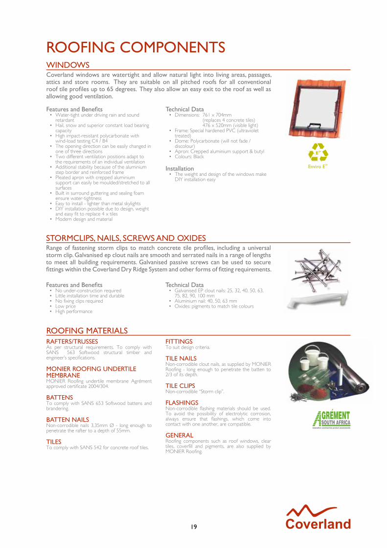
ROOFING COMPONENTSWINDOWSCoverland windows are watertight and allow natural light into living areas, passages, attics and store rooms. They are suitable on all pitched roofs for all conventional roof tile profiles up to 65 degrees. They also allow an easy exit to the roof as well as allowing good ventilation.
Features and Benefits• Water-tight under driving rain and sound
retardant• Hail, snow and superior constant load bearing
capacity• High impact-resistant polycarbonate with
wind-load testing C4 / B4• The opening direction can be easily changed in
one of three directions• Two different ventilation positions adapt to
the requirements of an individual ventilation• Additional stability because of the aluminium
step border and reinforced frame• Pleated apron with crepped aluminium
support can easily be moulded/stretched to all surfaces
• Built in surround guttering and sealing foam ensure water-tightness
• Easy to install - lighter than metal skylights• DIY installation possible due to design, weight
and easy fit to replace 4 x tiles• Modern design and material
Technical Data• Dimensions: 761 x 704mm
(replaces 4 concrete tiles) 476 x 520mm (visible light)
• Frame: Special hardened PVC (ultraviolet treated)
• Dome: Polycarbonate (will not fade / discolour)
• Apron: Crepped aluminium support & butyl• Colours: Black
Installation• The weight and design of the windows make
DIY installation easy
STORMCLIPS, NAILS, SCREWS AND OXIDESRange of fastening storm clips to match concrete tile profiles, including a universal storm clip. Galvanised ep clout nails are smooth and serrated nails in a range of lengths to meet all building requirements. Galvanised passive screws can be used to secure fittings within the Coverland Dry Ridge System and other forms of fitting requirements.
Features and Benefits• No under-construction required• Little installation time and durable• No fixing clips required• Low price• High performance
Technical Data• Galvanised EP clout nails: 25, 32, 40, 50, 63,
75, 82, 90, 100 mm• Aluminium nail: 40, 50, 63 mm• Oxides: pigments to match tile colours
RAFTERS/TRUSSESAs per structural requirements. To comply with SANS 563 Softwood structural timber and engineer’s specifications.
MONIER ROOFING UNDERTILE MEMBRANEMONIER Roofing undertile membrane Agrément approved certificate 2004/304.
BATTENSTo comply with SANS 653 Softwood battens and brandering.
BATTEN NAILSNon-corrodible nails 3,35mm Ø - long enough to penetrate the rafter to a depth of 55mm.
TILESTo comply with SANS 542 for concrete roof tiles.
FITTINGSTo suit design criteria.
TILE NAILSNon-corrodible clout nails, as supplied by MONIER Roofing - long enough to penetrate the batten to 2/3 of its depth.
TILE CLIPSNon-corrodible “Storm clip”.
FLASHINGSNon-corrodible flashing materials should be used. To avoid the possibility of electrolytic corrosion, always ensure that flashings, which come into contact with one another, are compatible.
GENERALRoofing components such as roof windows, clear tiles, coverfill and pigments, are also supplied by MONIER Roofing.
ROOFING MATERIALS

20
COOL ROOF SYSTEMHeat transmission can occur through three processes, namely radiation, conduction and convection. Radiation, which accounts for the lion’s share of heat transmitted within a home, causes discomfort within our sanctuaries.
RADENSHIELD is an integral part of the COOL ROOF system, as it is imbued with high reflectivity and low emissivity values which provide the perfect recipe to combat radiant heat. Due to high product performance and strength, RADENSHIELD is also used as an underlay. Its qualities prevent tearing during installation and ensure optimum and long-term product effectiveness. New products available in the DIY Product Package, RADENSHIELD™ ClimaGuard.
Benefits• Effective reflection of radiant heat (97%)• Easy installation• Save 30% on electricity• Decreases air conditioning usage by 40%• Up to 10°C cooler• Unique bonding process prevents delamination and tearing
COMPACTRIDGEThe Compactroll is a new and universal solution for dry ridges. It ventilates the ridge and is placed on the aligned ridge and hip battens. It is 100% mortar-free and is equipped with a water-tight high-tech UV resistant fleece.
COUNTER BATTENCreates a natural ventilation and stream to carry away hot air trapped between the roof tiles and the Radenshield.
EAVES FILLER COMBOne of the key components for ventilation. The MONIER Eaves Filler Comb promotes natural ventilation flow while keeping birds out of your roof.
RIDGE TREEThe Ridge Tree, which is a ridge and hip fixing device, allows for optimal alignment of the ridge and hip battens in the dry ridge system.
THE COMPLETE COOL ROOF SYSTEMCONSISTS OF THE FOLLOWING:
21
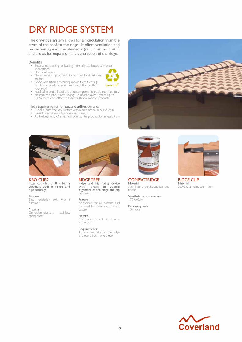
DRY RIDGE SYSTEMThe dry-ridge system allows for air circulation from the eaves of the roof, to the ridge. It offers ventilation and protection against the elements (rain, dust, wind etc.) and allows for expansion and contraction of the ridge.
Benefits• Ensures no cracking or leaking normally attributed to mortar
applications• No maintenance • The most stormproof solution on the South African
market• Good ventilation preventing mould from forming
which is a benefit to your health and the health of your roof
• Installed in one third of the time compared to traditional methods• Material and labour cost-saving: Compared over 3 years, up to
133% more cost-effective than traditional mortar products
The requirements for secure adhesion are:• A clean, dust free, dry surface within area of the adhesive edge• Press the adhesive edge firmly and carefully• At the beginning of a new roll overlap the product for at least 5 cm
KRO CLIPSFixes cut tiles of 8 - 16mm thickness both at valleys and hips securely.
FeatureEasy installation only with a hammer
Material Corrosion-resistant stainless spring steel
RIDGE TREERidge and hip fixing device which allows an optimal alignment of the ridge and hip battens.
FeatureApplicable for all battens and no need for removing the last batten
MaterialCorrosion-resistant steel wire and wood
Requirements: 1 piece per rafter at the ridge and every 60cm one piece
COMPACTRIDGEMaterialAluminium, polyisobutylen and fleece
Ventilation cross-section170 cm2/m
Packaging units10m rolls
RIDGE CLIPMaterialStove-enamelled aluminium
22
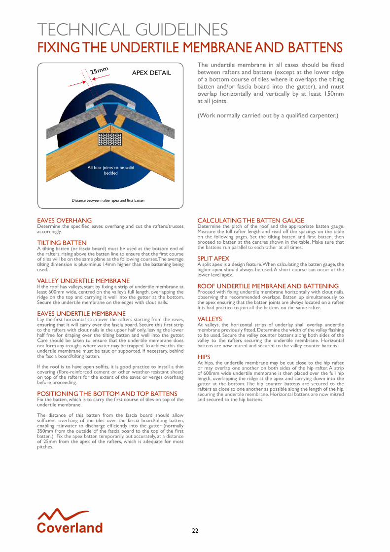
FIXING THE UNDERTILE MEMBRANE AND BATTENSThe undertile membrane in all cases should be fixed between rafters and battens (except at the lower edge of a bottom course of tiles where it overlaps the tilting batten and/or fascia board into the gutter), and must overlap horizontally and vertically by at least 150mm at all joints.
(Work normally carried out by a qualified carpenter.)
EAVES OVERHANGDetermine the specified eaves overhang and cut the rafters/trusses accordingly.
TILTING BATTENA tilting batten (or fascia board) must be used at the bottom end of the rafters, rising above the batten line to ensure that the first course of tiles will be on the same plane as the following courses. The average tilting dimension is plus-minus 14mm higher than the battening being used.
VALLEY UNDERTILE MEMBRANEIf the roof has valleys, start by fixing a strip of undertile membrane at least 600mm wide, centred on the valley’s full length, overlapping the ridge on the top and carrying it well into the gutter at the bottom. Secure the undertile membrane on the edges with clout nails.
EAVES UNDERTILE MEMBRANELay the first horizontal strip over the rafters starting from the eaves, ensuring that it will carry over the fascia board. Secure this first strip to the rafters with clout nails in the upper half only, leaving the lower half free for draping over the tilting batten and well into the gutter. Care should be taken to ensure that the undertile membrane does not form any troughs where water may be trapped. To achieve this the undertile membrane must be taut or supported, if necessary, behind the fascia board/tilting batten.
If the roof is to have open soffits, it is good practice to install a thin covering (fibre-reinforced cement or other weather-resistant sheet) on top of the rafters for the extent of the eaves or verges overhang before proceeding.
POSITIONING THE BOTTOM AND TOP BATTENSFix the batten, which is to carry the first course of tiles on top of the undertile membrane.
The distance of this batten from the fascia board should allow sufficient overhang of the tiles over the fascia board/tilting batten, enabling rainwater to discharge efficiently into the gutter (normally 350mm from the outside of the fascia board to the top of the first batten.) Fix the apex batten temporarily, but accurately, at a distance of 25mm from the apex of the rafters, which is adequate for most pitches.
CALCULATING THE BATTEN GAUGEDetermine the pitch of the roof and the appropriate batten gauge. Measure the full rafter length and read off the spacings on the table on the following pages. Set the tilting batten and first batten, then proceed to batten at the centres shown in the table. Make sure that the battens run parallel to each other at all times.
SPLIT APEXA split apex is a design feature. When calculating the batten gauge, the higher apex should always be used. A short course can occur at the lower level apex.
ROOF UNDERTILE MEMBRANE AND BATTENINGProceed with fixing undertile membrane horizontally with clout nails, observing the recommended overlaps. Batten up simultaneously to the apex ensuring that the batten joints are always located on a rafter. It is bad practice to join all the battens on the same rafter.
VALLEYSAt valleys, the horizontal strips of underlay shall overlap undertile membrane previously fitted. Determine the width of the valley flashing to be used. Secure the valley counter battens along both sides of the valley to the rafters securing the undertile membrane. Horizontal battens are now mitred and secured to the valley counter battens.
HIPSAt hips, the undertile membrane may be cut close to the hip rafter, or may overlap one another on both sides of the hip rafter. A strip of 600mm wide undertile membrane is then placed over the full hip length, overlapping the ridge at the apex and carrying down into the gutter at the bottom. The hip counter battens are secured to the rafters as close to one another as possible along the length of the hip, securing the undertile membrane. Horizontal battens are now mitred and secured to the hip battens.
TECHNICAL GUIDELINES
23
WINDLOADINGS AND UNDERTILE MEMBRANES
BATTEN CENTRES
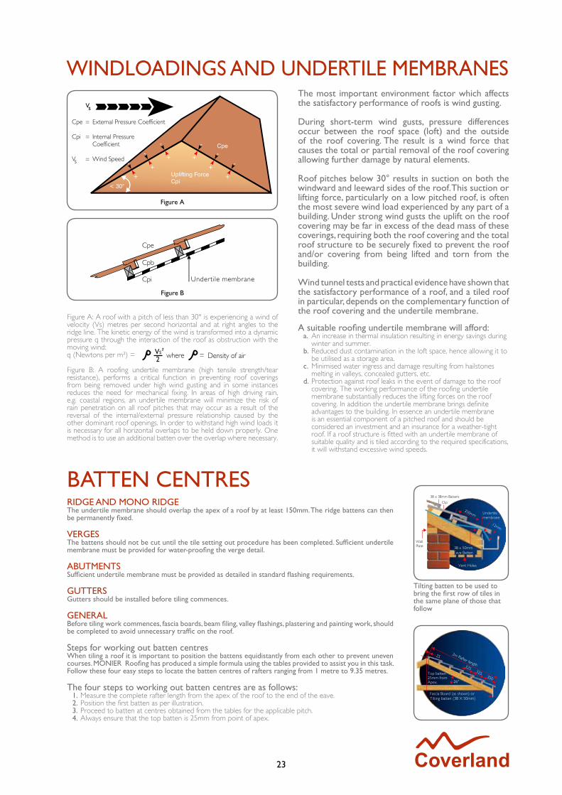
The most important environment factor which affects the satisfactory performance of roofs is wind gusting.
During short-term wind gusts, pressure differences occur between the roof space (loft) and the outside of the roof covering. The result is a wind force that causes the total or partial removal of the roof covering allowing further damage by natural elements.
Roof pitches below 30° results in suction on both the windward and leeward sides of the roof. This suction or lifting force, particularly on a low pitched roof, is often the most severe wind load experienced by any part of a building. Under strong wind gusts the uplift on the roof covering may be far in excess of the dead mass of these coverings, requiring both the roof covering and the total roof structure to be securely fixed to prevent the roof and/or covering from being lifted and torn from the building.
Wind tunnel tests and practical evidence have shown that the satisfactory performance of a roof, and a tiled roof in particular, depends on the complementary function of the roof covering and the undertile membrane.
Figure A: A roof with a pitch of less than 30° is experiencing a wind of velocity (Vs) metres per second horizontal and at right angles to the ridge line. The kinetic energy of the wind is transformed into a dynamic pressure q through the interaction of the roof as obstruction with the moving wind:q (Newtons per m²) =
Figure B: A roofing undertile membrane (high tensile strength/tear resistance), performs a critical function in preventing roof coverings from being removed under high wind gusting and in some instances reduces the need for mechanical fixing. In areas of high driving rain, e.g. coastal regions, an undertile membrane will minimize the risk of rain penetration on all roof pitches that may occur as a result of the reversal of the internal/external pressure relationship caused by the other dominant roof openings. In order to withstand high wind loads it is necessary for all horizontal overlaps to be held down properly. One method is to use an additional batten over the overlap where necessary.
A suitable roofing undertile membrane will afford:a. An increase in thermal insulation resulting in energy savings during
winter and summer.b. Reduced dust contamination in the loft space, hence allowing it to
be utilised as a storage area.c. Minimised water ingress and damage resulting from hailstones
melting in valleys, concealed gutters, etc.d. Protection against roof leaks in the event of damage to the roof
covering. The working performance of the roofing undertile membrane substantially reduces the lifting forces on the roof covering. In addition the undertile membrane brings definite advantages to the building. In essence an undertile membrane is an essential component of a pitched roof and should be considered an investment and an insurance for a weather-tight roof. If a roof structure is fitted with an undertile membrane of suitable quality and is tiled according to the required specifications, it will withstand excessive wind speeds.
RIDGE AND MONO RIDGEThe undertile membrane should overlap the apex of a roof by at least 150mm. The ridge battens can then be permanently fixed.
VERGESThe battens should not be cut until the tile setting out procedure has been completed. Sufficient undertile membrane must be provided for water-proofing the verge detail.
ABUTMENTSSufficient undertile membrane must be provided as detailed in standard flashing requirements.
GUTTERSGutters should be installed before tiling commences.
GENERALBefore tiling work commences, fascia boards, beam filing, valley flashings, plastering and painting work, should be completed to avoid unnecessary traffic on the roof.
Steps for working out batten centresWhen tiling a roof it is important to position the battens equidistantly from each other to prevent uneven courses. MONIER Roofing has produced a simple formula using the tables provided to assist you in this task. Follow these four easy steps to locate the batten centres of rafters ranging from 1 metre to 9.35 metres.
The four steps to working out batten centres are as follows:1. Measure the complete rafter length from the apex of the roof to the end of the eave.2. Position the first batten as per illustration.3. Proceed to batten at centres obtained from the tables for the applicable pitch.4. Always ensure that the top batten is 25mm from point of apex.
Tilting batten to be used to bring the first row of tiles in the same plane of those that follow
24
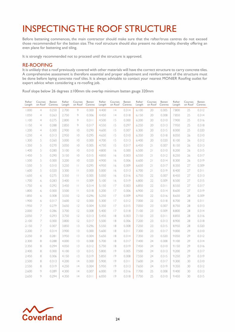
INSPECTING THE ROOF STRUCTUREBefore battening commences, the main contractor should make sure that the rafter/truss centres do not exceed those recommended for the batten size. The roof structure should also present no abnormality, thereby offering an even plane for battening and tiling.
It is strongly recommended not to proceed until the structure is approved.
RE-ROOFINGIt is unlikely that a roof previously covered with other materials will have the correct structure to carry concrete tiles. A comprehensive assessment is therefore essential and proper adjustment and reinforcement of the structure must be done before laying concrete roof tiles. It is always advisable to contact your nearest MONIER Roofing outlet for expert advice when considering a re-roofing job.
Roof slope below 26 degrees ±100mm tile overlap minimum batten gauge 320mm
Rafter Length
Courses on Roof
Batten Centres
Rafter Length
Courses on Roof
Batten Centres
Rafter Length
Courses on Roof
Batten Centres
Rafter Length
Courses on Roof
Batten Centres
Rafter Length
Courses on Roof
Batten Centres
1.000 4 0.250 2.700 9 0.300 4.400 14 0.314 6.100 20 0.305 7.800 25 0.312
1.050 4 0.263 2.750 9 0.306 4.450 14 0.318 6.150 20 0.308 7.850 25 0.314
1.100 4 0.275 2.800 9 0.311 4.500 15 0.300 6.200 20 0.310 7.900 25 0.316
1.150 4 0.288 2.850 9 0.317 4.550 15 0.297 6.250 20 0.313 7.950 25 0.318
1.200 4 0.300 2.900 10 0.290 4.600 15 0.307 6.300 20 0.315 8.000 25 0.320
1.250 4 0.313 2.950 10 0.295 4.650 15 0.310 6.350 20 0.318 8.050 26 0.310
1.300 5 0.260 3.000 10 0.300 4.700 15 0.313 6.400 20 0.320 8.100 26 0.312
1.350 5 0.270 3.050 10 0.305 4.750 15 0.317 6.450 21 0.307 8.150 26 0.313
1.400 5 0.280 3.100 10 0.310 4.800 16 0.300 6.500 21 0.310 8.200 26 0.315
1.450 5 0.290 3.150 10 0.315 4.850 16 0.303 6.550 21 0.312 8.250 26 0.317
1.500 5 0.300 3.200 10 0.320 4.900 16 0.306 6.600 21 0.314 8.300 26 0.319
1.550 5 0.310 3.250 11 0.295 4.950 16 0.309 6.650 21 0.317 8.350 27 0.309
1.600 5 0.320 3.300 11 0.300 5.000 16 0.313 6.700 21 0.319 8.400 27 0.311
1.650 6 0.275 3.350 11 0.305 5.050 16 0.316 6.750 22 0.307 8.450 27 0.313
1.700 6 0.283 3.400 11 0.309 5.100 16 0.319 6.800 22 0.309 8.500 27 0.315
1.750 6 0.292 3.450 11 0.314 5.150 17 0.303 6.850 22 0.311 8.550 27 0.317
1.800 6 0.300 3.500 11 0.318 5.200 17 0.306 6.900 22 0.314 8.600 27 0.319
1.850 6 0.308 3.550 12 0.296 5.250 17 0.309 6.950 22 0.316 8.650 28 0.309
1.900 6 0.317 3.600 12 0.300 5.300 17 0.312 7.000 22 0.318 8.700 28 0.311
1.950 7 0.279 3.650 12 0.304 5.350 17 0.315 7.050 23 0.307 8.750 28 0.313
2.000 7 0.286 3.700 12 0.308 5.400 17 0.318 7.100 23 0.309 8.800 28 0.314
2.050 7 0.293 3.750 12 0.313 5.450 18 0.303 7.150 23 0.311 8.850 28 0.316
2.100 7 0.300 3.800 12 0.317 5.500 18 0.306 7.200 23 0.313 8.900 28 0.318
2.150 7 0.307 3.850 13 0.296 5.550 18 0.308 7.250 23 0.315 8.950 28 0.320
2.200 7 0.314 3.900 13 0.300 5.600 18 0.311 7.300 23 0.317 9.000 29 0.310
2.250 8 0.281 3.950 13 0.304 5.650 18 0.314 7.350 23 0.320 9.050 29 0.312
2.300 8 0.288 4.000 13 0.308 5.700 18 0.317 7.400 24 0.308 9.100 29 0.314
2.350 8 0.294 4.050 13 0.312 5.750 18 0.319 7.450 24 0.310 9.150 29 0.316
2.400 8 0.300 4.100 13 0.315 5.800 19 0.305 7.500 24 0.313 9.200 29 0.317
2.450 8 0.306 4.150 13 0.319 5.850 19 0.308 7.550 24 0.315 9.250 29 0.319
2.500 8 0.313 4.200 14 0.300 5.900 19 0.311 7.600 24 0.317 9.300 30 0.310
2.550 8 0.319 4.250 14 0.304 5.950 19 0.313 7.650 24 0.319 9.350 30 0.312
2.600 9 0.289 4.300 14 0.307 6.000 19 0.316 7.700 25 0.308 9.400 30 0.313
2.650 9 0.294 4.350 14 0.311 6.050 19 0.318 7.750 25 0.310 9.450 30 0.315

25
INSPECTING THE ROOF STRUCTURE
CUTTING AND DRILLING OF TILES
Roof slope 26 degrees and above ±75mm tile overlap minimum batten gauge 345mm
Rafter Length
Courses on Roof
Batten Centres
Rafter Length
Courses on Roof
Batten Centres
Rafter Length
Courses on Roof
Batten Centres
Rafter Length
Courses on Roof
Batten Centres
Rafter Length
Courses on Roof
Batten Centres
1.000 3 0.333 2.700 8 0.338 4.400 13 0.338 6.100 18 0.339 7.800 23 0.3391.050 4 0.263 2.750 8 0.344 4.450 13 0.342 6.150 18 0.342 7.850 23 0.3411.100 4 0.275 2.800 9 0.311 4.500 14 0.321 6.200 18 0.344 7.900 23 0.3431.150 4 0.288 2.850 9 0.317 4.550 14 0.325 6.250 19 0.329 7.950 24 0.3311.200 4 0.300 2.900 9 0.322 4.600 14 0.329 6.300 19 0.332 8.000 24 0.3331.250 4 0.313 2.950 9 0.328 4.650 14 0.332 6.350 19 0.334 8.050 24 0.3351.300 4 0.325 3.000 9 0.333 4.700 14 0.336 6.400 19 0.337 8.100 24 0.3381.350 4 0.338 3.050 9 0.339 4.750 14 0.339 6.450 19 0.339 8.150 24 0.3401.400 5 0.280 3.100 9 0.344 4.800 14 0.343 6.500 19 0.342 8.200 24 0.3421.450 5 0.290 3.150 10 0.315 4.850 15 0.323 6.550 19 0.345 8.250 24 0.3441.500 5 0.300 3.200 10 0.320 4.900 15 0.327 6.600 20 0.330 8.300 25 0.3321.550 5 0.310 3.250 10 0.325 4.950 15 0.330 6.650 20 0.333 8.350 25 0.3341.600 5 0.320 3.300 10 0.330 5.000 15 0.333 6.700 20 0.335 8.400 25 0.3361.650 5 0.330 3.350 10 0.335 5.050 15 0.337 6.750 20 0.338 8.450 25 0.3381.700 5 0.340 3.400 10 0.340 5.100 15 0.340 6.800 20 0.340 8.500 25 0.3401.750 6 0.292 3.450 10 0.345 5.150 15 0.343 6.850 20 0.343 8.550 25 0.3421.800 6 0.300 3.500 11 0.318 5.200 16 0.325 6.900 20 0.345 8.600 25 0.3441.850 6 0.308 3.550 11 0.323 5.250 16 0.328 6.950 21 0.331 8.650 26 0.3331.900 6 0.317 3.600 11 0.327 5.300 16 0.331 7.000 21 0.333 8.700 26 0.3351.950 6 0.325 3.650 11 0.332 5.350 16 0.334 7.050 21 0.336 8.750 26 0.3372.000 6 0.333 3.700 11 0.336 5.400 16 0.338 7.100 21 0.338 8.800 26 0.3382.050 6 0.342 3.750 11 0.341 5.450 16 0.341 7.150 21 0.340 8.850 26 0.3402.100 7 0.300 3.800 11 0.345 5.500 16 0.344 7.200 21 0.343 8.900 26 0.3422.150 7 0.307 3.850 12 0.321 5.550 17 0.326 7.250 21 0.345 8.950 26 0.3442.200 7 0.314 3.900 12 0.325 5.600 17 0.329 7.300 22 0.332 9.000 27 0.3332.250 7 0.321 3.950 12 0.329 5.650 17 0.332 7.350 22 0.334 9.050 27 0.3352.300 7 0.329 4.000 12 0.333 5.700 17 0.335 7.400 22 0.336 9.100 27 0.3372.350 7 0.336 4.050 12 0.338 5.750 17 0.338 7.450 22 0.339 9.150 27 0.3392.400 7 0.343 4.100 12 0.342 5.800 17 0.341 7.500 22 0.341 9.200 27 0.3412.450 8 0.306 4.150 13 0.319 5.850 17 0.344 7.550 22 0.343 9.250 27 0.3432.500 8 0.313 4.200 13 0.323 5.900 18 0.328 7.600 23 0.330 9.300 27 0.3442.550 8 0.319 4.250 13 0.327 5.950 18 0.331 7.650 23 0.333 9.350 28 0.3342.600 8 0.325 4.300 13 0.331 6.000 18 0.333 7.700 23 0.335 9.400 28 0.3362.650 8 0.331 4.350 13 0.335 6.050 18 0.336 7.750 23 0.337 9.450 28 0.338
HEALTH AND SAFETY INSTRUCTION
Many building products such as roof tiles are manufactured using raw materials. These raw materials contain a proportion of crystalline silica. Powered mechanical processing such as cutting or drilling of the products will release some quantities of respirable silica dust. Where exposure to this dust is high and prolonged over time, it can lead to lung disease (silicosis) and an increase risk of lung cancer where silicosis has been contracted.
The following control measures are required:• An approved P3/FFP3 particulate respirator must be used during
all cutting and drilling processes.• In addition, engineering control such as wet cutting or dust
extraction devices should be applied.
For cutting and drilling, control measures are required.Wet cutting or dust extraction should be applied.
Ear protection Eye protection Respiratory protection – dusk mask type P3/FFP3

26
TILINGAscertain the mechanical fixing requirements as per the laying and fixing specifications (as supplied by your nearest MONIER Roofing branch). Roofs to be tiled in accordance with SANS 062.
STARTING TILINGTile to the lines from the right-hand side, working towards the left, and moving upwards. Simultaneously secure the tiles as required, and install eave fillers where necessary.
All Coverland tiles should be laid “straight-bond” except for the Elite which must be laid “broken-bond”. Full tiles are marked to facilitate ease of laying to the lines.
MECHANICAL FIXINGShould be in accordance with the laying and fixing specifications.Where clips are used, they should be fixed to the battens. The clips should be at the tail of each tile - as close to the batten as the head of the tile beneath it permits.
CUTTING TILESPurpose-made cut tiles for use at hips and valleys are not manufactured because the position of the cut varies from tile to tile. Cutting of tiles is done on-site, either traditionally by hand or mechanically.
VALLEYSExtra care should be taken with the valley construction because of its lower pitch in relation to the rest of the roof and the fact that it drains water away from the slopes. The small tile sections should be secured to the valley battens to keep the valley clear and unobstructed and prevent water from overflowing into the roof space.
CAUTION!Sand, which is used as an aggregate in making concrete, contains silica which is released in dust when mechanical dry cutting of tiles is performed. Inhalation over a long period of time could cause silicosis.
It is recommended that a dust mask to a protection level of FFP3 and eye protection be worn as a safety precaution. Alternatively, wet cutting of tiles is recommended to contain the release of dust (see index).
HIPSThe tiles from the two adjacent slopes should be cut closely and secured on the hip rafter to provide adequate support for the bedding of ridge tiles. Hip anchors should be used at the bottom edge of each hip rafter on steep pitches.
It is essential to fix all cut tiles carefully at hips and valleys to retain them in position. This can be achieved by using a kro clip or by using an adhesive such as Coverfill.
OPEN VALLEYOnce the valley battens have been positioned, a gutter is then formed in the valley using a suitable non-corrodible material. The fascia board is cut away so that no part of the valley gutter is raised above the fascia board when laid. The tiles on each side of the valley should be neatly cut to alignment and laid in such a way that they project over the side welt by at least 50mm. A gap of at least 50mm should be provided in the centre of the valley between the cut edges of the tiles.
CLOSED VALLEYProceed as indicated above, with the exception that the tile should be cut in order to form a neat butt joint in the centre of the valley. Best achieved by cutting one side completely, using a straight edge before starting the other side.
Useful tips1. In order to avoid damage, ladders against or into eaves’ gutters
should be clear of the gutters and then securely anchored. It is dangerous to rest a ladder against a verge owing to the uneven line of support and its greater susceptibility to damage.
2. Materials or tools required should be carried up and not drawn or dragged over the roof. Materials stacked on the roof should not overload the battens, undertile membrane or roof structure, and should preferably be placed on the rafter lines.
3. Care should be taken when walking on the roof. It is bad practice to walk up the valleys and hips. When walking on the tiles always step on the bottom middle of the tile.

27
EFFLORESCENCE
MORTAR BEDDING
Efflorescence, often referred to as “lime bloom”, is a natural phenomenon and is found in products containing cement. It is a white deposit which appears on the surface of all concrete based products. Efflorescence is a temporary condition, and does not affect the functional properties of the product.
Wind and rain will gradually remove the deposit and the true colour of the tile will be restored.
CAUSES OF EFFLORESCENCEConcrete consists of sand, gravel, cement and water - with the cement being produced by burning alumina and lime together with other elements. Water in the form of rain, condensation or dew dissolves part of the lime. A barely soluble white film of lime is created by this chemical reaction and is seen on the surface of the tile when the water evaporates.
HOW IS EFFLORESCENCE REMOVED?The natural process of weathering (e.g. rain water washing over the tiles), will wash the chalky deposit away, and the true colour of the tile will be restored.
CAN EFFLORESCENCE BE REMOVED ARTIFICIALLY?A diluted acid mix can be applied as a short-term measure. It is, however, the recommended and accepted practice to allow nature to remove the deposit.
CAN EFFLORESCENCE RE-APPEAR?In some instances, efflorescence may recur temporarily. Since the lime content of any concrete product can vary and the weather conditions can also differ, the level of the lime deposit on the surface can also fluctuate considerably. Efflorescence is a natural phenomenon and a temporary condition only.
BEDDING OF HIPS(As per bedding of ridges in 10 easy steps) Bed into position a hip starter. Temporarily bed a ridge at the apex of the hip. Run a levelling line between the hip starter and the top ridge. Proceed to bed ridges from the hip starter to the apex, keeping to the line.
BEDDING OF MONO RIDGESThe same recommendations for ridges, in 10 easy steps, apply (see pages 33-35).
BEDDING OF TAPERED RIDGEThe same recommendations, as for ridges, apply with the exception that the overlapping joints are caulked and not solidly bedded.
DRY RIDGE SYSTEMWhere possible, a dry ridge system is preferable to bedded ridges. On pitches of 40° and above, the 90° Barge tile is recommended for use as a ridge and hip tile.
NOTE: MONIER recommends the Lumino tile range selection to prevent efflorescence.
Caulking
50mm
Bedding for butt joint
Caulking of tapered ridge
GENERAL SUPPORT INFORMATION
28
RAKE VERGE
INSTALLATION PROCEDURE
EXAMPLE 1Double Roman& Taunus
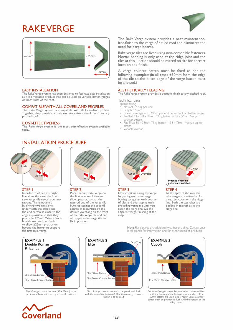
The Rake Verge system provides a neat maintenance-free finish to the verge of a tiled roof and eliminates the need for barge boards.
Rake verge tiles are fixed using non-corrodible fasteners. Mortar bedding is only used at the ridge joint and the tiles at this junction should be mitred on site for correct location and finish.
A verge counter batten must be fixed as per the following examples: (in all cases ±30mm from the edge of the tile to the outer edge of the verge batten must be allowed.)
EASY INSTALLATIONThe Rake Verge system has been designed to facilitate easy installation as it is a versatile product that can be used on variable batten gauges on both sides of the roof.
COMPATIBLE WITH ALL COVERLAND PROFILESThe Rake Verge system is compatible with all Coverland profiles. Together, they provide a uniform, attractive overall finish to any pitched roof.
COST-EFFECTIVENESSThe Rake Verge system is the most cost-effective system available today.
AESTHETICALLY PLEASINGThe Rake Verge system provides a beautiful finish to any pitched roof.
Technical dataTapered fitting
• Mass of ±5,4kg per unit• Length 420mm • Linear coverage = ±320mm per unit dependent on batten gauge• Profiled Tiles: 38 x 38mm Tiling batten = 38 x 50mm Verge
counter batten• Flat Tiles: 38 x 38mm Tiling batten = 38 x 76mm Verge counter
batten• Variable overlap
STEP 1In order to obtain a straight line along the eave, the first rake verge tile needs a dummy spacing. This is obtained by driving two nails, one underneath the other, into the end batten as close to the edge as possible so that they protrude ±25mm. Where fascia boards are used, cut fascia to allow ±25mm protrusion beyond the batten to support the first rake verge.
Top of verge counter battens (38 x 50mm) to be positioned flush with the top of the tile battens.
Top of verge counter battens to be positioned flush with the top of tile battens. A 38 x 76mm verge counter
batten is to be used.
Bottom of verge counter battens to be positioned flush with the bottom of tile battens. In cases where 38 x 50mm battens are used, a 38 x 76mm verge counter
batten must be positioned flush with the bottom of the tiling batten.
Note: Flat tiles require additional weather proofing. Consult your local branch for information and for other specialist products.
STEP 2Place the first rake verge on the first course of tiles and slide upwards, so that the tapered end of the verge tile butts up against the second course of tiles. Mark off the desired overhang on the front of the rake verge tile and cut off. Replace the verge tile and fix in position.
STEP 3Now continue along the verge by placing each rake verge butting up against each course of tiles and overlapping each preceding verge tile until you reach the ridge line. Do the adjacent verge, finishing at the ridge.
STEP 4At the apex of the roof the rake verges are mitred to form a neat junction with the ridge line. Both the top rakes are bedded in mortar as in the ridge line.
EXAMPLE 2Elite
EXAMPLE 3Cupola
29
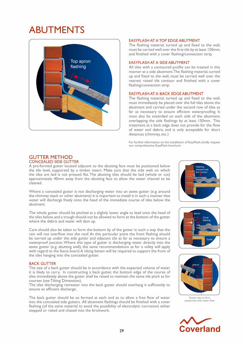
ABUTMENTSEASYFLASH AT A TOP EDGE ABUTMENTThe flashing material, turned up and fixed to the wall, must be carried well over the first tile by at least 150mm, and finished with a cover flashing/connection strip.
EASYFLASH AT A SIDE ABUTMENTAll tiles with a contoured profile can be treated in this manner at a side abutment. The flashing material, turned up and fixed to the wall, must be carried well over the nearest raised tile contour and finished with a cover flashing/connection strip.
EASYFLASH AT A BACK EDGE ABUTMENTThe flashing material, turned up and fixed to the wall, must immediately be placed over the full tiles above the abutment and carried under the second row of tiles as far as necessary to ensure efficient waterproofing. It must also be extended on each side of the abutment, overlapping the side flashings by at least 150mm. This treatment at a back edge does not provide for the flow of water and debris, and is only acceptable for short distances (chimney, etc.)
For further information on the installation of EasyFlash, kindly request our comprehensive EasyFlash brochure.
GUTTER METHODCONCEALED SIDE GUTTERA pre-formed gutter located adjacent to the abutting face must be positioned below the tile level, supported by a timber insert. Make sure that the side welt on which the tiles are laid is not pressed flat. The abutting tiles should be laid (whole or cut) approximately 40mm away from the abutting face to allow the water channel to be cleaned.
Where a concealed gutter is not discharging water into an eaves gutter (e.g. around the chimney stack or other abutment) it is important to install it in such a manner that water will discharge freely onto the head of the immediate course of tiles below the abutment.
The whole gutter should be pitched at a slightly lower angle to lead onto the head of the tiles below, and a trough should not be allowed to form at the bottom of the gutter where the debris and water will dam up.
Care should also be taken to form the bottom lip of the gutter in such a way that the rain will not overflow into the roof. At this particular point the front flashing should be carried up under the side gutter and adjacent tile as far as necessary to ensure a waterproof junction. Where this type of gutter is discharging water directly into the eaves gutter (e.g. abutting wall), the same recommendations as for a valley will apply with regard to the fascia board. A tilting batten will be required to support the front of the tiles hanging into the concealed gutter.
BACK GUTTERThe size of a back gutter should be in accordance with the expected volume of water it is likely to carry. In constructing a back gutter, the bottom edge of the course of tiles immediately above the gutter shall be raised to maintain the same tile pitch as for courses (see Tilting Dimension). The tiles discharging rainwater into the back gutter should overhang it sufficiently to ensure an efficient discharge.
The back gutter should be so formed at each end as to allow a free flow of water into the concealed side gutters. All abutment flashings should be finished with a cover flashing (of the same material to avoid the possibility of electrolytic corrosion) either stepped or raked and chased into the brickwork.
Gutter size to be in proportion with water flow
30
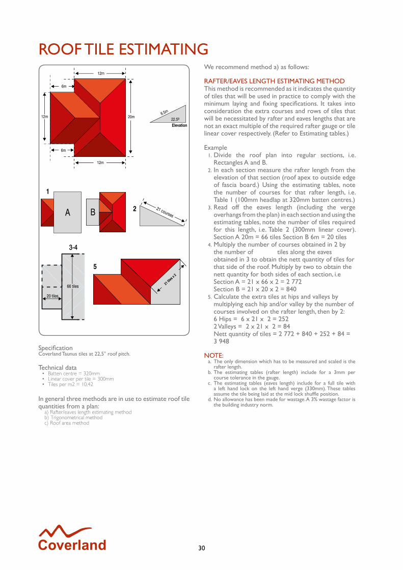
ROOF TILE ESTIMATINGWe recommend method a) as follows:
RAFTER/EAVES LENGTH ESTIMATING METHODThis method is recommended as it indicates the quantity of tiles that will be used in practice to comply with the minimum laying and fixing specifications. It takes into consideration the extra courses and rows of tiles that will be necessitated by rafter and eaves lengths that are not an exact multiple of the required rafter gauge or tile linear cover respectively. (Refer to Estimating tables.)
Example1. Divide the roof plan into regular sections, i.e.
Rectangles A and B.2. In each section measure the rafter length from the
elevation of that section (roof apex to outside edge of fascia board.) Using the estimating tables, note the number of courses for that rafter length, i.e. Table 1 (100mm headlap at 320mm batten centres.)
3. Read off the eaves length (including the verge overhangs from the plan) in each section and using the estimating tables, note the number of tiles required for this length, i.e. Table 2 (300mm linear cover). Section A 20m = 66 tiles Section B 6m = 20 tiles
4. Multiply the number of courses obtained in 2 by the number of tiles along the eaves obtained in 3 to obtain the nett quantity of tiles for that side of the roof. Multiply by two to obtain the nett quantity for both sides of each section, i.e Section A = 21 x 66 x 2 = 2 772 Section B = 21 x 20 x 2 = 840
5. Calculate the extra tiles at hips and valleys by multiplying each hip and/or valley by the number of courses involved on the rafter length, then by 2: 6 Hips = 6 x 21 x 2 = 252 2 Valleys = 2 x 21 x 2 = 84 Nett quantity of tiles = 2 772 + 840 + 252 + 84 = 3 948
NOTE:a. The only dimension which has to be measured and scaled is the
rafter length.b. The estimating tables (rafter length) include for a 3mm per
course tolerance in the gauge.c. The estimating tables (eaves length) include for a full tile with
a left hand lock on the left hand verge (330mm). These tables assume the tile being laid at the mid lock shuffle position.
d. No allowance has been made for wastage. A 3% wastage factor is the building industry norm.
SpecificationCoverland Taunus tiles at 22,5° roof pitch.
Technical data• Batten centre = 320mm• Linear cover per tile = 300mm• Tiles per m2 = 10,42
In general three methods are in use to estimate roof tile quantities from a plan: a) Rafter/eaves length estimating method b) Trigonometrical method c) Roof area method

31
ESTIMATING TABLESTable 1
Number of tiles per rafter length Number of tiles per rafter length
At
m
320 mm batten centres
345 mm batten centres
At
m
320 mm batten centres
345 mm batten centres
2,000 7 6 6,000 19 182,200 7 7 6,100 19 182,300 8 7 6,200 20 182,400 8 7 6,300 20 192,500 8 8 6,400 20 192,600 9 8 6,500 21 192,700 9 8 6,600 21 192,800 9 9 6,700 21 202,900 9 9 6,800 22 203,000 10 9 6,900 22 203,100 10 9 7,000 22 213,200 10 10 7,100 22 213,300 11 10 7,200 23 213,400 11 10 7,300 23 213,500 11 11 7,400 23 223,600 12 11 7,500 24 223,700 12 11 7,600 24 223,800 12 11 7,700 24 233,900 13 12 7,800 25 234,000 13 12 7,900 25 234,100 13 12 8,000 25 234,200 13 134,300 14 134,400 14 134,500 14 134,600 15 144,700 15 144,800 15 144,900 16 155,000 16 155,100 17 155,200 17 155,300 17 165,400 17 165,500 18 165,600 18 175,700 18 175,800 18 175,900 19 17
Table 1Number of tiles per eaves length Number of tiles per eaves length
At 300 mmm
linearcover
At 300 mmm
linearcover
1,830 6 14,130 472,130 7 14,430 482,430 8 14,730 492,730 9 15,030 503,030 10 15,330 513,330 11 15,630 523,630 12 15,930 533,930 13 16,230 544,230 14 16,530 554,530 15 16,830 564,830 16 17,130 575,130 17 17,430 585,430 18 17,730 595,730 19 18,030 606,030 20 18,330 616,330 21 18,630 626,630 22 18,930 636,930 23 19,230 647,230 24 19,530 657,530 25 19,830 667,830 26 20,130 678,130 27 20,430 688,430 28 20,730 698,730 29 21,030 709,030 30 21,330 719,330 31 21,630 729,630 32 21,930 739,930 33 22,230 7410,230 34 22,530 7510,530 3510,830 3611,130 3711,430 3811,730 3912,030 4012,330 4112,630 4212,930 4313,230 4413,530 4513,830 46
This table indicates the number of tiles which must be allowed per given eaves length, assuming that the tiles are laid to the nominal linear cover of 300mm per tile.
All figures are nett. Wastage must be added.
This table indicates the number of courses which must be allowed per given rafter length to ensure that the minimum headlap of 75mm or 100mm is obtained. Rafter lengths from roof apex to outside edge of fascia are assumed.
All figures are nett. Wastage must be added.

32
LAYING AND FIXING SPECIFICATIONSRecommended laying and fixing specifications for Coverland concrete roof tiles.
The following laying and fixing specifications for Coverland concrete roof tiles have been established in accordance with SANS 062/1956 (Code of Practice for fixing concrete roof tiles), SANS 0160/1980 (Code of Practice for the general procedures and loadings to be adopted for the design of buildings), BS 5534 - Part 1/1978 (Code of Practice for slating and tiling and design), MONIER Roofing technology data, and extensive experience gained by MONIER Roofing.
Roofs in exposed and coastal areas can experience severe wind lifting forces. In these situations special recommendations for additional mechanical fixings apply. The principal factors to be considered in deciding on the necessity for additional fixing are:
1. The exposure of the site.2. The height above ground of the roof.3. The pitch of the roof.4. The higher wind loadings encountered at eaves and verges.5. Environmental influences.
Specific laying and fixing specifications for these locations must be considered for each situation.
DEFINITIONSRAFTER PITCHThe angle of elevation between the horizontal plane and the angle of the rafter. Roof pitch = rafter pitch
TILE PITCHThe angle of elevation between horizontal and the tile when laid. Note: The tile pitch has a lower angle of elevation than the rafter pitch.
Low roof pitch 17° to 25°Normal roof pitch 26° to 35°High roof pitch 36° and above
LAYING SPECIFICATIONSHEADLAPSThe minimum headlap for Coverland concrete roof tiles is 100mm on 17°-25° and 75mm on pitches of 26° and above. All Coverland concrete roof tiles, with the exception of the Elite, should be laid “straight-bond”.
MECHANICAL FIXINGCoastal regions (up to 30km inland):Aluminium alloy/Non-corrodible serrated clouthead nails of the correct length to suit the profile.
INLAND REGIONS:Electroplated serrated clouthead nails of the correct length to suit the profile. Non-corrodible “stormclips” should always be used where specified. Ensure correct stormclip is used for specific profiles.
FIXING SPECIFICATIONSThe following fixing guide should provide a sound functional roof in each of the defined exposure categories. However, it cannot encompass all possible circumstances, or the unanticipated worse than the “once in 50 years” prediction. Special laying and fixing specifications must be considered for each situation where the roof pitch, height of the roof, exposure of the site and/or environmental influence are unknown, in doubt, or felt to be critical. Please refer to MONIER Roofing for advice in these circumstances.
MECHANICAL FIXINGCupola 100 mm long nail/clipped
Clay Tile 50 mm long nail/clipped
Double Roman 63 mm long nail/clipped
Elite 50 mm long nail/clipped
Taunus 75 mm long nail/clipped
Rake Verge 75 mm long nail
Tile Clips 50 mm long nail
Tile Clips for Elite 25 mm long nail
* Nails to be 2.8 mm gauge serrated shank type.
33
LAYING AND FIXING SPECIFICATIONSCATEGORY A - UNEXPOSED AREASAll inland regions other than certain specified areas.
CATEGORY B - SEMI-EXPOSED AREASCoastal regions and certain inland areas.Generally the area within 30km from the coastline, the top of the escarpment or the watershed of the first mountain inland. Whilst cognizance should be taken of local practices, the application of good roofing practice should not be compromised for expediency.
CATEGORY C - EXPOSED AREASCritical coastal areas, and certain inland areas.
The classification of exposure categories assumes the use of a suitable underlay, properly fixed over the total area of the roof including the gable end and eave overhangs.
When possible, local knowledge and local wind speed data should be used in the assessment of the exposure category. (Refer to SANS 0160/1980 for Regional Basic Design Wind Speed determination.)
FIXING GUIDECATEGORY A - UNEXPOSED AREASAll inland regions other than certain specified areas.
Mechanically fix two courses of tiles at the eaves, ridge and verges for the full overhang, whichever is greater. Cut tiles at hips, valleys and abutments to be secured with kro clips or coverfill.It is recommended that closed soffits be fitted on all verge and eave overhangs.
Roof pitches17° to < 26° - undertile membrane mandatory26° to < 45° - undertile membrane recommended45° to < 55° - undertile membrane recommended, each tile to be nailed55° to vertical - undertile membrane mandatory, each tile to be nailed and clipped
CATEGORY B - SEMI-EXPOSED AREASCoastal regions and certain inland areas.
Mechanically fix a band of tiles (x) equal to a fifth of the number of courses on the rafter lengths at the eaves and ridges, and also at chimneys and abutments.Mechanically fix a band of tiles equal to (x) along (y), as calculated above, at each verge (or the full overhang, whichever is the greater.) Tiles at hips, valleys and abutments to be secured with kro clips to every third tile on the roof.Closed soffits must be fitted to all verge and eave overhangs.
Roof pitches17° to < 26° - undertile membrane mandatory26° to < 45° - undertile membrane recommended (mandatory at the coast)45° to vertical - undertile membrane mandatory, each tile to be nailed and clipped
CATEGORY C - EXPOSED AREASCritical coastal areas and certain inland areas.
Roof pitches17° to < 26° - undertile membrane mandatory, each tile to be clipped26° to < 45° - undertile membrane mandatory, each tile to be nailed or clipped45° to vertical - undertile membrane mandatory, each tile to be nailed and clippedClosed soffits to be fitted at all verge and eave overhangs.
The exposure category of the required roof may be assessed using the flowwing table:
Height to Ridge not exeeding M
Regional Basic DesignWind Speed ms-1
Exposure Category
5 40 and below41 to 49 inclusive 50 and above
ABC
10 43 and below44 to 49 inclusive 50 and above
ABC
15 42 and below43 to 47 inclusive 48 and above
ABC
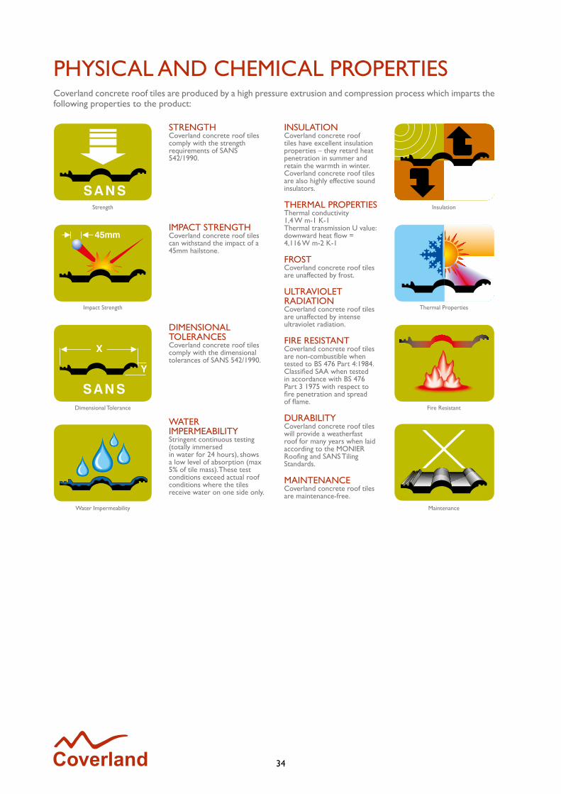
34
PHYSICAL AND CHEMICAL PROPERTIES
STRENGTHCoverland concrete roof tiles comply with the strength requirements of SANS 542/1990.
IMPACT STRENGTH Coverland concrete roof tiles can withstand the impact of a 45mm hailstone.
DIMENSIONAL TOLERANCESCoverland concrete roof tiles comply with the dimensional tolerances of SANS 542/1990.
WATER IMPERMEABILITYStringent continuous testing (totally immersed in water for 24 hours), shows a low level of absorption (max 5% of tile mass). These test conditions exceed actual roof conditions where the tiles receive water on one side only.
INSULATIONCoverland concrete roof tiles have excellent insulation properties – they retard heat penetration in summer and retain the warmth in winter. Coverland concrete roof tiles are also highly effective sound insulators.
THERMAL PROPERTIESThermal conductivity 1,4 W m-1 K-1Thermal transmission U value:downward heat flow = 4,116 W m-2 K-1
FROSTCoverland concrete roof tiles are unaffected by frost.
ULTRAVIOLET RADIATIONCoverland concrete roof tiles are unaffected by intense ultraviolet radiation.
FIRE RESISTANTCoverland concrete roof tiles are non-combustible when tested to BS 476 Part 4:1984.Classified SAA when tested in accordance with BS 476 Part 3 1975 with respect to fire penetration and spread of flame.
DURABILITYCoverland concrete roof tiles will provide a weatherfast roof for many years when laid according to the MONIER Roofing and SANS Tiling Standards.
MAINTENANCECoverland concrete roof tiles are maintenance-free.
Coverland concrete roof tiles are produced by a high pressure extrusion and compression process which imparts the following properties to the product:
Strength Insulation
Impact Strength
Dimensional Tolerance Fire Resistant
Water Impermeability Maintenance
Thermal Properties
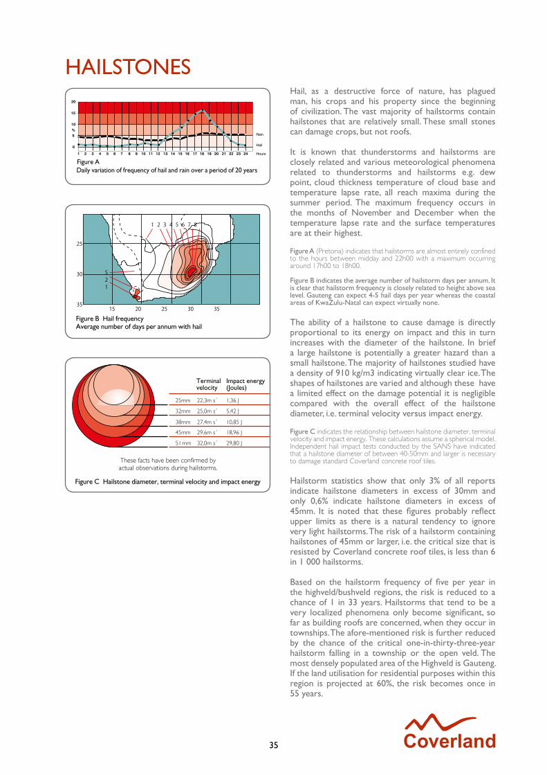
35
HAILSTONESHail, as a destructive force of nature, has plagued man, his crops and his property since the beginning of civilization. The vast majority of hailstorms contain hailstones that are relatively small. These small stones can damage crops, but not roofs.
It is known that thunderstorms and hailstorms are closely related and various meteorological phenomena related to thunderstorms and hailstorms e.g. dew point, cloud thickness temperature of cloud base and temperature lapse rate, all reach maxima during the summer period. The maximum frequency occurs in the months of November and December when the temperature lapse rate and the surface temperatures are at their highest.
Figure A (Pretoria) indicates that hailstorms are almost entirely confined to the hours between midday and 22h00 with a maximum occurring around 17h00 to 18h00.
Figure B indicates the average number of hailstorm days per annum. It is clear that hailstorm frequency is closely related to height above sea level. Gauteng can expect 4-5 hail days per year whereas the coastal areas of KwaZulu-Natal can expect virtually none.
The ability of a hailstone to cause damage is directly proportional to its energy on impact and this in turn increases with the diameter of the hailstone. In brief a large hailstone is potentially a greater hazard than a small hailstone. The majority of hailstones studied have a density of 910 kg/m3 indicating virtually clear ice. The shapes of hailstones are varied and although these have a limited effect on the damage potential it is negligible compared with the overall effect of the hailstone diameter, i.e. terminal velocity versus impact energy.
Figure C indicates the relationship between hailstone diameter, terminal velocity and impact energy. These calculations assume a spherical model. Independent hail impact tests conducted by the SANS have indicated that a hailstone diameter of between 40-50mm and larger is necessary to damage standard Coverland concrete roof tiles.
Hailstorm statistics show that only 3% of all reports indicate hailstone diameters in excess of 30mm and only 0,6% indicate hailstone diameters in excess of 45mm. It is noted that these figures probably reflect upper limits as there is a natural tendency to ignore very light hailstorms. The risk of a hailstorm containing hailstones of 45mm or larger, i.e. the critical size that is resisted by Coverland concrete roof tiles, is less than 6 in 1 000 hailstorms.
Based on the hailstorm frequency of five per year in the highveld/bushveld regions, the risk is reduced to a chance of 1 in 33 years. Hailstorms that tend to be a very localized phenomena only become significant, so far as building roofs are concerned, when they occur in townships. The afore-mentioned risk is further reduced by the chance of the critical one-in-thirty-three-year hailstorm falling in a township or the open veld. The most densely populated area of the Highveld is Gauteng. If the land utilisation for residential purposes within this region is projected at 60%, the risk becomes once in 55 years.

36
10 EASY STEPS TO TILING A ROOF1. TOOLS REqUIRED• Saw• Chalkline• Tape measure• Pointing trowel• Hammer• Brush• Nail bag
2. TRUSS CENTRESMaximum 760mm 38mm x 38mm Batten.Maximum 900mm 38mm x 50mm Batten on edge.Elite tile 950mm 38mm x 50mm Batten on edge.Always consult your timber merchant for truss design and timber sizes.
1) Truss centres must be equal and correct distances apart.2) Apex - Truss heights must be level!
3. ROOF UNDERTILE MEMBRANEa. Coastal areas - mandatory at all pitches.b. Other areas - 17° - 25° - mandatory 26° - 45° - optional (recommended).c. Lay undertile membrane on top of trusses & under battens.d. Elite profile - undertile membrane mandatory at all pitches.
All specifications detailed are for a single storey domestic building – consult your nearest outlet for other applications.
4. EAVES APEXa. The tilting fillet must always be ±12mm thicker
than the tile battens.b. From the outside of the tilting fillet/fascia to the
top of the first batten 350mm.c. The top of the apex batten must be 25mm from
the top of the truss.
5. BATTEN CENTRESRoof Pitches 17° - 25° 320mm maximum26° - 45° 345mm maximumCentres should never be below 300mm.
a. Obtain measurement Y and divide either by 320mm or 345mm dependent on pitch.
b. The figure obtained is rounded e.g. measurement Y = 4.325m ÷ 320mm = 13.51 (rounded = 14).
c. The rounded figure (14) is then divided into Y, this will then give exact batten centre e.g. 4.325m ÷ 14 = 309mm centres.
d. Now batten roof at 309mm centres. Always join battens on alternating trusses i.e. not all joints must be on the same truss.

37
10 EASY STEPS TO TILING A ROOF6. MARKING YOUR ROOF OUT
a. Always mark your roof out.b. Gable overhang not to exceed more than one tile.c. Lay a course out at the eaves, shuffle this to get desired
overhang (each tile has 1.5mm shuffle).d. Ensure tiles are seated properly, corner break can occur if
this is not done.e. Run one row of tiles up right hand gable, keeping square to
bottom row.f. Run a course of tiles along apex of roof. Tiles must be laid
loose and not tight against each other to allow for thermal movement.
g. Mark outside edge of underlock of every fourth tile and shoot chalkline to corresponding tiles top and bottom.
NOTE: MONIER recommends the Dry Ridge System for the laying of ridges.
7. LOADING OF ROOFThe roof can now be loaded; commence by stacking in bundles of seven tiles working from apex of roof down towards eaves. The bundles of seven tiles must be stacked on top of the rafters on alternate battens. Both sides of the roof to be equally loaded.
9. FIXING EXPOSED AREAS OF TILESCoastal - aluminium alloy or non-corrodible serrated clouthead nails of the correct length to suit the profile. Inland - electroplated serrated clouthead nails.
a. Coastal regions - all tiles to be mechanically fixed. Eaves to be closed.
b. Unexposed areas - all exposed eaves to be nailed/clipped, all tiles in ridge course to be nailed/clipped, thereafter every third tile in every row to be nailed/clipped.
c. Always ensure at least one row in from exposed areas is nailed/clipped.
Contact your nearest outlet for details, regarding mechanically fixing requirements.
10. BEDDING OF RIDGESa. Mix to a fairly dry workable consistency 3 parts sharp
graded sand, one part portland cement and colorant (plus-minus 1kg pigment per 50kgs cement.)
b. Run a 225mm strip of DPC along the ridge line. c. Exception: CT - Run a 150mm strip of Malthoid along the
ridge line.d. Soak ridge in water to provide wet joint with mortar.e. Bed at each end of the roof one ridge in a bed of mortar -
50mm wide and 75mm high. Press ridges into mortar.f. Run a gut line between the two bedded ridges.g. Proceed to lay ridges keeping to line.h. Only butt joints of ridges to be solid bedded, remainder of
ridges to be edge bedded.i. All pointing to be neatly struck off.j. Roof to be brushed and cleaned off.k. Any damaged tiles within the roof to be replaced.l. In some coastal areas the ridge tiles are solid bedded.m. Contact your nearest outlet if in doubt.
8. LAYING OF TILESa. Proceed to lay tiles from right to left keeping to chalk lines,
lay three rows at a time. b. When walking on tiles always step on the bottom middle
of the tile.
38
NOTES

39
NOTES

40
NOTES

41
2
6
10
13
14
17
4 5
8
9
73
111
15
16
12
40
ROOF STRUCTURE TERMINOLOGY
CAUTION!Sand, which is used as an aggregate in making concrete, contains silica which is released in dust when mechanical dry cutting of tiles is performed. Inhalation over a long period of time could cause silicosis.It is recommended that a dust mask to a protection level of FFP3 and eye protection be worn as a safety precaution. Alternatively, wet cutting of tiles is recommended to contain the release of dust (see p72).
NOTICE:• Although MONIER Roofing has compiled this document as accurately as possible, discrepancies may occur in construction methods due to
flexibilities in the building industry.• Information contained in this brochure is provided in an advisory capacity and MONIER Roofing accepts no liability for work executed by
contractors or private individuals.• MONIER Roofing reserves the right to change any information herein at their discretion without prior notification.• Contact your nearest MONIER Roofing Branch for an approved Roofing Contractor.• Raw materials used in the production process differ at the various branches and may cause colour differences in the finished product.
Special colours are available on request in all profiles but subject to minimum quantities. Colours may vary due to printing processes and MONIER Roofing suggests actual viewing of the tile samples.
Whilst illustrations depict the Coverland Taunus tile, the practices apply to all Coverland profiles. Any exceptions will be indicated in bold typeface.
1. Wall plate2. Truss3. Valley rafter4. Hip rafter5. Batten6. Eaves7. Tilting batten8. Fascia board9. Verge counter batten10. Tie beams11. Sprocket end12. Bracing13. Apex14. junction15. Rafter16. Hip counter batten17. Valley counter batten
42
NAMIBIA
BOTSWANA
NORTHERN CAPE
WESTERN CAPE
EASTERN CAPE
FREE STATE
NORTH WEST
MPUMALANGA
KWAZULUNATAL
LIMPOPO
GAUTENG
Constantia View Office Estate, Block #32 Hogsback RoadQuellerina, Gauteng, South AfricaT 011 222 7300F 011 222 7470
www.coverland.co.za
BloemfonteinHeatherdale RoadBloemfontein T 087 741 3000F 087 741 3014
Brits27 Piet Rautenbach StreetBrits Industrial AreaT 012 250 2964F 012 250 2218
Cape TownMoorsom AvenueEpping 2 T 021 534 1441F 021 534 7851
Durban NorthKwa Mashu RoadAvoca EstateT 031 565 3260F 031 565 1312
Germiston5 Setchell RoadRoodekopT 011 866 2462F 011 866 2941
Port Elizabeth6 Kurland RoadPerseverance T 041 463 1155F 041 463 2629
queensburgh19 Bougainvilla DriveQueensburghT 031 489 9860F 031 464 2247
Richards Bay14 Geleirgang AltonRichards BayT 035 797 2160F 035 797 4096
VereenigingBarrage Road VereenigingT 016 430 8000F 016 430 8071
CamperdownUmlaas RoadCamperdownT 031 785 1093F 031 785 1093
East London4 Signal RoadQuigneyT 043 743 2189F 043 743 2191
GeorgePearl StreetTamsui Industrial SiteT 044 878 1324F 044 878 1325
HEAD OFFICE
BRANCHES
DEPOTS
6794
GR
APH
IC IM
PRIN
T &
086
1 77
468
1
Part of the MONIER GROUP