product installation, dimensions & configurations
TRANSCRIPT

1
A GUIDE TOProduct Installation,
Dimensions & Configurations

Jonas & James - Product Installation, Dimensions & Product Information 2
CONTENTS
Release date: July 2020
Installation Heights
Door Configurations Standard Units Hadleigh True Handleless Units
Cabinets Installation Fittings Appliance Housing Drill Hole Guides L-shape Corners with Vertical Bi-fold Doors Belfast Units Boiler Housing Bridging Units Wall Microwave Housing
Corner Planning Corner Base Units Guide to Lh/Rh Wirework Units Corner Wall Units
Curved Units End Panels Wall End Panel Heights End Panel Grain / T&G Direction
Wirework Installation
Hadleigh Kitchens Hadleigh True Handleless Installation Hadleigh Larder & Appliance Housing
Drawers Drawer Front Marking Tool SmartLarder Internal Drawers Drawer Runner Positions
3
4
9
18
12
13
14
6789
18
9
19
16
12
15
10
20
1716
13
5

Jonas & James - Product Installation, Dimensions & Product Information 3
INSTALLATION HEIGHTS
Standard Height Installation1970mm
Extra Tall Height Installation2150mm
Base Cab
Plinth
18-22mm
28/3
8/40
mm
600mm
490m
m(b
ased
on
40m
m w
orkt
op)
560mm
150
mm
*
*adjustable height
300mm
720m
m
1970
mm
2120
mm
*
720m
m
WallCab
Base Cab
Plinth
18-22mm
28/3
8/40
mm
600mm
490m
m(b
ased
on
40m
m w
orkt
op)
560mm
150
mm
*
*adjustable height
300mm
900m
m
2150
mm
2300
mm
*
720m
m
TallWallCab

Jonas & James - Product Installation, Dimensions & Product Information 4
DOOR CONFIGURATIONS
EXTRA TALL LARDER & APPLIANCE UNIT CONFIGURATIONSExtra tall height installation (2150mm).
Standard UnitsBASE & WALL UNIT CONFIGURATIONSStandard height installation (1970mm) & extra tall height installation (2150mm).
LARDER & APPLIANCE UNIT CONFIGURATIONSStandard height installation (1970mm).
715
150mm plinth
140 140 83 Internal140140140140
140
355 355283
283
175
175
175
175
570 450 490
600 (w)Belfast Sink 355 355
895895
Glazed715 715
Glazed355
355355
110
2150
mm
1970
mm
150m
m
150m
m
600
Wall and base units are available in various widths, please see price list for more info.
140140
895
895
175
1965
Availablewidths:
300400500600
150mm plinth
Larder Unit, Full Height
Doors(Slab only)
LarderUnit
70/30
Fridge / Freezer50/50
(980 doors)
FF50 FF70 FF90 TOVENA TOVENB TOVENC TOVEND TOVENE TOVENF
Fridge / Freezer50/50
(895 doors)
Single Oven & 380mm
Micro
Single Oven & 460mm
Micro
Double Oven
Dble Oven& 283mm
drawers
Fridge / Freezer70/30
Single Oven
Sgle Oven& 355mm
drawers
1245
715
1970
mm
150m
m
355
355
490 490
715
645 645450
450570 490
490
460
600
600 600
600
900 900
380
283
283
1245
Availablewidths:
300400500600
715
980
980
490490
fillerfiller
715715
110110
175175
600600 900900
283570
283
355715
355
TTOVENA TTOVENB TTOVENC TTOVEND TTOVENE TTOVENFTFF50 TFF70
Fridge / Freezer50/50
Single Oven & 460mm
Micro
Single Oven & 380mm
Micro
Fridge / Freezer70/30
150mm plinth
LarderUnit
Double Oven
Dble Oven& 283mm
drawers
SingleOven
Sgle Oven& 355mm
drawers
1245
895895
175490
450
980
980
140
2150
mm
150m
m
460
600
1245
Availablewidths:
300400500600
All dimensions shown in mm.
NB: This page is to show door configurations only. Appliance heights will vary and may have an impact on filler / door sizes. Please check appliance heights and specifications before purchasing and installing any units to ensure they fit the door configurations specified and are suitable for your requirements.
600 (w)Belfast Sink
This code is unique to this appliance unit & added to the end of the order code.
Undermountinstallation
Aproninstallation
570
570
600
380
L30-L6030FHD-60FHD
TL30-TL60
This code is unique to this appliance unit & added to the end of the order code.

Jonas & James - Product Installation, Dimensions & Product Information 5
DOOR CONFIGURATIONS
TFF50STFF50D
Fridge / Freezer50/50
175
980
980
895
895
175
685
150mm plinth*
83 Internal 160160
325 325
325
895715
355
355355
110
490
1965
Availablewidths:
300400500600
1245
Availablewidths:
300400500600
150mm plinth*
Larder Unit, Full Height
Doors(Slab only)
LarderUnit
70/30
FF50SFF50D
L30S-L60SL30D-L60D
TL30S-TL60STL30D-TL60D
FF70SFF70D
FF90SFF90D
TOVENASTOVENAD
TTOVENASTTOVENAD
TOVENBSTOVENBD
TTOVENBSTTOVENBD
TOVENCSTOVENCD
TTOVENCSTTOVENCD
TOVENDSTOVENDD
TTOVENDSTTOVENDD
TFF70STFF70D
Fridge / Freezer50/50
(980 doors)
Fridge / Freezer50/50
(895 doors)
Single Oven & 460mm
Micro
Single Oven & 380mm
Micro
Double Oven
Fridge / Freezer70/30
Fridge / Freezer70/30
Single Oven
1245
715715 715
645
980
980
450
450570 490
490
490
570
150mm plinth*
LarderUnit
Double Oven
SingleOven
1245
895895715
490
450
filler
715
110
140175
2150
mm
2150
mm
1970
mm
1970
mm
150m
m*
150m
m*
460
460
600
600
600
600
600
600
900
900
380
Units are available in different widths, please check price list.
1245
Availablewidths:
300400500600
150m
m*
150m
m*
Hadleigh True Handleless UnitsHADLEIGH BASE & WALL UNIT CONFIGURATIONSStandard height installation (1970mm) & extra tall height installation (2150mm).
Wall profile (fitted behind
door)
Top profile (for base units)
Hadleigh wall unit door sizes are the same as standard door sizes as the Hadleigh wall
profile is fitted behind the door.
Hadleigh base unit doors are designed specifically to suit Hadleigh base profiles
and are shorter than standard doors, using 685mm rather than 715mm.
Hadleigh larder & appliance unit door sizes are the same as standard door sizes.
HADLEIGH LARDER & APPLIANCE UNIT CONFIGURATIONSStandard height installation (1970mm).
EXTRA TALL HADLEIGH LARDER & APPLIANCE UNIT CONFIGURATIONSExtra tall height installation (2150mm).
NB: This page is to show door configurations only. Appliance heights will vary and may have an impact on filler / door sizes. Please check appliance heights and specifications before purchasing and installing any units to ensure they fit the door configurations specified and are suitable for your requirements.
* Cabinet leg height required may vary. If integrated under counter appliances are installed, please raise cabinet legs with min. 10mm (throghout the kitchen) to ensure the appliance fits easily underneath the top rail.
Single Oven & 380mm
Micro
Single Oven & 460mm
Micro
filler
filler
filler
filler
This code is unique to this
appliance unit & added to the
end of the order code.
Codes ending with an ‘S’ is a
single gable and ending in a
‘D’ is a double gable.
See p. 17 for more information
570
570
600
380
Vertical profile (for larder/appliance units)
See p. 17 for more information
All dimensions shown in mm.
FH30S-FH60SFH30D-FH60D

Jonas & James - Product Installation, Dimensions & Product Information 6
CABINETS
Installation Fittings
Base Cabinet
Wall CabinetExample pack contents for standard Double Wall and Double Base cabinets.
Metal shelf pegs
Metal shelf pegs
Black carcase screws (for centre post)
Black carcase screws (for centre post)
Cabinet legs & plinth clips
Door buffers
Worktop fixing blocks
Door buffers
Hinge pack:2 sets of hinges, 16mm screws,
18mm mounting plates with Euro screws, hinge plate
covers and cam plate covers.
Hinge pack:2 sets of hinges, 16mm screws,
18mm mounting plates with Euro screws, hinge plate
covers and cam plate covers.
Crossrail used for drawer lin
e units
(discard if not needed)
5mm colour co-ordinated drill hole cover caps
5mm colour co-ordinated drill hole cover caps
Wall plates & hangers
Plates
Hangers
Hole covers(metal)
Basic installation:1. Push the wall hangers into the
sides of the back of the wall units.2. Attach the wall plates to wall
(screws & plugs not supplied). 3. Hang wall unit on to wall plates.
Basic installation:1. Push against the wall.2. Secure to wall using L-brackets.

Jonas & James - Product Installation, Dimensions & Product Information 7
CABINETS
9.5mm
573.5mm
1472mm
Product code: JXXXUTOVENE
Description: Double Oven with 283mm drawers x 2
PRE-DRILLED HOLES - APPLIANCE UNITS
L-9.5mm
Leng
th (L
) 197
0mm
1852mm
1561mm
55mm
340mm
32mm
1674mm
Fixed shelf positionsKEY:
Drawer runner positions
Hinge positions
Floating shelf positions (optional)
GABLE END TOP
GABLE END BOTTOM
JXXXUTOVENE
APPLIANCE UNIT
GABLE END LEFT
Used for 283mm
drawer runner (bottom)
Used for bottomfixed shelf
Used for top fixed shelf
Used for fixed shelf
for 283 + 283mm
drawer config.
Used for fixed shelf for
490mm door config.
Used for 490mm door
hinge holes (top)
Used for 490mm door
hinge holes (bottom)
Used for optional floating
shelf (1 supplied in pack)
Used for 283mm
drawer runner (top)
Measurements taken
from BOTTOM of gable
end to hole centre.
283mm (h)
drawer front
283mm (h)
drawer front
490mm (h)door
900mm (h)
double oven
9.5mm
573.5mm
1472mm
Product code: JXXXUTOVENE
Description: Double Oven with 283mm drawers x 2 PRE-DRILLED HOLES - APPLIANCE UNITS
L-9.5mm
Leng
th (L
) 197
0mm
1852mm
1561mm
55mm
340mm
32mm
1674mm
Fixed shelf positions
KEY:
Drawer runner positions
Hinge positions
Floating shelf positions (optional)
GABLE END TOP
GABLE END BOTTOM
JXXXUTOVENE
APPLIANCE UNIT
GABLE END LEFT
Used for 283mm
drawer runner (bottom)
Used for bottom
fixed shelf
Used for top fixed shelf
Used for fixed shelf
for 283 + 283mm
drawer config.
Used for fixed shelf for
490mm door config.
Used for 490mm door
hinge holes (top)
Used for 490mm door
hinge holes (bottom)Used for optional floating
shelf (1 supplied in pack)
Used for 283mm
drawer runner (top)
Measurements taken
from BOTTOM of gable
end to hole centre.
283mm (h)
drawer front
283mm (h)
drawer front
490mm (h)
door
900mm (h)
double oven
Appliance Housing Drill Hole Guides
• Our appliance housings come with pre-drilled holes for shelf positions, door hinges and drawer runners, covering most of the appliance unit configurations available in our price list.
• Use the drill hole guides to locate pre-drilled holes for your appliance units and to find info about any holes you need to drill yourself.
• Includes 1970mm & 2150mm height units.
Shelf positions, hinge holes & drawer runners
Configurations included in the drill hole guides:
895
895
175
150mm plinth
Fridge / Freezer50/50 (980 doors)
Fridge / Freezer50/50
(895 doors)
Single Oven & 380
Microwave
Single Oven & 460
Microwave
Double Oven
Double Ovenwith
drawers
Fridge / Freezer70/30
Single Oven
Single Ovenwith
drawers
1245
715
355
355
490 490
715
645 645450
450570 490
490
460
600
600 600
600
900 900
380
283
283
980
980
490490
fillerfiller
715715
110110
175175
600600 900900
283570
283
355
715
355
Fridge / Freezer50/50
Single Oven & 460
Microwave
Single Oven & 380
Microwave
Fridge / Freezer70/30
150mm plinth
Double Oven
Double Ovenwith
drawers
SingleOven
SingleOvenwith
drawers
1245
895
175
490
450
980
980
140
460
600
Appliance Housing
Standard installation height (1970mm)
Extra Tall Appliance Housing
Extra tall installation height (2150mm)
570
570
600
380
FF50 FF70 FF90 TOVENA TOVENB TOVENC TOVEND TOVENE TOVENF
TTOVENA TTOVENB TTOVENC TTOVEND TTOVENE TTOVENFTFF50 TFF70
View appliance housing drill hole guides here:www.jonasandjames.co.uk/techguides

Jonas & James - Product Installation, Dimensions & Product Information 8
CABINETS
L-shape corners with vertical bi-fold doors
Our L-shape 900 x 900mm base & 600 x 600mm wall units come with ‘vertical bi-fold’ doors.Pie Cut and 165° hinges are used for these doors which is included with the cabinet.Nb. Corner posts not needed for these units.
How to install vertical bi-fold doors:1. Attach door 1 to door 2 using the Pie Cut hinges
(door 2 comes with pre-drilled holes for hinge cups).2. Place centre of screw holes for Pie Cut hinge plates
37mm from the front of door 1, same as when attaching a standard hinge to a cabinet.
3. Attach doors to cabinet with the 165° hinges.4. Use the additional adjustment screw on Pie Cut
hinges to adjust gap between bi-fold doors.
165° hingePie cut hinge
KEY
Doors closed
Doors half open
Doors fully open
L Shape Corner Unit
165° hingePie cut hinge
KEY
Doors closed
Doors half open
Doors fully open
L Shape Corner UnitHinge positions:
Hinges (included with cabinet):
165° hingePie Cut hinge
Door 1
Door 1
Door 2 Door 2
1. Doors closed 2. Doors half open 3. Doors fully open
L-shape corner unit doors:
Pie Cut hinge 165° hinge

Jonas & James - Product Installation, Dimensions & Product Information 9
CABINETS
Belfast Units
Boiler Housing
490mm (h)door
450mm (h)door
Belfast Sink
UndermountInstallation
Apron InstallationWorktop WorktopWorktop Worktop
Belfast Sink
600mm
• Our Belfast Sink Units are 600mm wide to accommodate 600m wide Belfast sinks (purchased separately).
• Available in 450mm or 490mm height to allow for undermount or apron installation (see illustration).
Boilers vary in size & position. Here’s how to create your own bespoke housing.
• As boilers are generally deeper than the 300mm depth of our tall wall cabinets you must bring the wall cabinet forward and attach the cabinet to the end panels (min. depth 400mm).
• The end panels need to be securely attached to the wall with L-brackets.
1. Tall Wall Unit 900 x 600mm (leaving back panel out) Includes: 900mm height tall wall cabinet with 895 x 596mm door & 110 degree hinges.
2. Base End Panel 900 x 650mm, cut to 900 x 400mm size. Optionally use a Tall End Panel 2400 x 650mm cut to size if end panel needs to run down to the worktop.
3. L-brackets
What you need:
Please note: Boilers vary in size and there is no set standard. This will have an effect on filler/door/end panel sizes, please check boiler dimensions carefully prior to installation to ensure the housing is suitable for the boiler it’s being used for. It’s the installers responsibility to ensure the housing is fitted correctly and in line with boiler safety regulations.
600mm
Belfast Sink
Belfast Unit
450/
490m
m
Bridging UnitsHinge hole positions:
Front of cabinet
37m
m
Inside top panel
• Bridging unit doors are hinged on the top panel of the cabinet.
• The centre of the screw holes for the hinge plates to be placed 37mm from front of cabinet, the same as for a standard side hinged door.
• 1 x gas lift needed for smaller doors, 2 x gas lifts for larger doors. See ‘Door Lift Mechanisms’ tech guide for more info (link below).
View Door Lift Mechanisms technical guide here:www.jonasandjames.co.uk/techguides
32mm
86mm
900m
m
BOILEREN
D P
ANEL
TALL WALL UNIT 900x600mm
Void to accommodateback of boiler
Min.400mm 600mm
300mmL-brackets
Code: BEL455 Code: BEL495
Jonas & James - Product Installation, Dimensions & Product Information 10
CABINETS
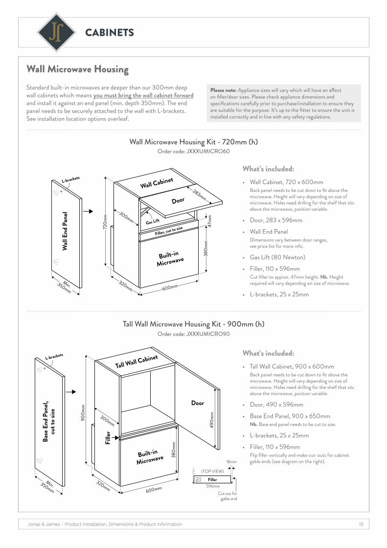
Wall Microwave HousingStandard built-in microwaves are deeper than our 300mm deep wall cabinets which means you must bring the wall cabinet forward and install it against an end panel (min. depth 350mm). The end panel needs to be securely attached to the wall with L-brackets. See installation location options overleaf.
Please note: Appliance sizes will vary which will have an affect on filler/door sizes. Please check appliance dimensions and specifications carefully prior to purchase/installation to ensure they are suitable for the purpose. It’s up to the fitter to ensure the unit is installed correctly and in line with any safety regulations.
• Wall Cabinet, 720 x 600mm Back panel needs to be cut down to fit above the microwave. Height will vary depending on size of microwave. Holes need drilling for the shelf that sits above the microwave, position variable.
• Door, 283 x 596mm
• Wall End Panel Dimensions vary between door ranges, see price list for more info.
• Gas Lift (80 Newton)
• Filler, 110 x 596mm Cut filler to approx. 47mm height. Nb. Height required will vary depending on size of microwave.
• L-brackets, 25 x 25mm
• Tall Wall Cabinet, 900 x 600mm Back panel needs to be cut down to fit above the microwave. Height will vary depending on size of microwave. Holes need drilling for the shelf that sits above the microwave, position variable.
• Door, 490 x 596mm
• Base End Panel, 900 x 650mm Nb. Base end panel needs to be cut to size.
• L-brackets, 25 x 25mm
• Filler, 110 x 596mm Flip filler vertically and make cut-outs for cabinet gable ends (see diagram on the right).
What’s included:
What’s included:
Wall Microwave Housing Kit - 720mm (h)
Tall Wall Microwave Housing Kit - 900mm (h)
Order code: JXXXUMICRO60
Order code: JXXXUMICRO90
Built-inMicrowave
Door
Wall Cabinet
Filler, cut to sizeGas Lift
320mm
300mm
47m
m
600mm
380m
m
720m
m
283mm
L-brackets
Wall
End
Pan
el
Min.350mm
600mm
Built-in
Microwave
Tall Wall Cabinet
Fille
r
Door
300mm
900m
m
320mm
380m
m
490m
m
110
596mm
18mm
Cut out forgable end
(TOP VIEW)
Fillermm
L-brackets
Min.350mm
Base
End
Pan
el,cu
t to s
ize

Jonas & James - Product Installation, Dimensions & Product Information 11
CABINETS
600mm
350m
mEn
d Pa
nel
Door / front of micro
L-bracket
Filler (cut down from end panel)
WALL
WAL
L
Wall Cabinet
300m
m
320mm deep micro
Wall Microwave HousingInstallation location options
Corner Installation
Installation next to Larder Unit
Installation next to standard Wall Units
320mm deep micro
Door / front of micro
Door
600mm
350m
mEn
d Pa
nel
L-bracket
WALL
Wall Cabinet
Larder Cabinet
300m
m
320mm deep micro
Door / front of micro
Door Door600mm
350m
mEn
d Pa
nel
L-bracket
WALL
Wall Cabinet
L-bracket
300m
m Wall Cabinet Wall Cabinet
(TOP VIEW)

Jonas & James - Product Installation, Dimensions & Product Information 12
CORNER PLANNING
Guide to LH / RH Wirework Corner Units
LHWirework unit
LHDoor
RHBlanking panel
Corner base cabinet
RHWirework unit
LHBlanking panel
RHDoor
Corner base cabinet
Corner postCorner post
Units are ‘handed’ by the side the door is on.
Product Code: 80CB4 Base Unit: 800mm (w) Door size: 396mm (w) x 715mm (h) Blanking panel: 500mm (w), can be cut to size
Product Code: 10CB6 Base Unit: 1000mm (w) Door size: 596mm (w) x 715mm (h) Blanking panel: 500mm (w), can be cut to size
Product Code: 90CB Base Unit: 900mm (w) Door size: 446mm (w) x 715mm (h) Blanking panel: 500mm (w), can be cut to size
Product Code: CBASE Base Unit: 900 x 900mm L-shape Door size: 2 x 313mm (w) x 715mm (h) Hinges: 165° and Pie-cut Corner hinges to be used for the bi-fold corner door
* PLEASE NOTE: Dimensions are based on 70 x 70mm Salcombe slab corner post. Corner post sizes vary between ranges which affects the size of the required distance from wall to end of corner cabinet. Please make sure the distance is adjusted to reflect the size of the corner post for the specific door range.
Eg. Hamilton J-pull corner posts are 60 x 60mm which means distance from wall to end of corner cabinet is 10mm shorter.
Void is covered by the worktop after installation.
Product Code: 10CB5 Base Unit: 1000mm (w) Door size: 496mm (w) x 715mm (h) Blanking panel: 500mm (w), can be cut to size
1030*800
560800
Corner Cabinet
396Door
500Blanking
Panel
70 x 70CornerPost*
230*
560Base Cabinet
Depth
Void
1080*900
900Corner Cabinet
446Door
500Blanking
Panel
560
180*
560Base Unit Depth
70 x 70CornerPost*
Void
1000
5601000
Corner Cabinet
496Door
500Blanking
Panel
560Base Unit Depth
70 x 70CornerPost*
130* Void
1130*
1000
5601000
Corner Cabinet
596Door
500Blanking
Panel
230* Void
560Base Unit Depth
70 x 70CornerPost*
1230*
900 x 900L Shape Corner
Base Cabinet
90090
0
2 x 313Doors
Corner Base Units All dimensions shown in mm.

Jonas & James - Product Installation, Dimensions & Product Information 13
CORNER PLANNING / CURVED UNITS
Curved Units
(TOP VIEW)
(TOP VIEW)
(FRONT VIEW)
Curved Door Radius
Curved Door Heights Curved Unit Sizes
Curved Wall Unit
Curved Base / Extra Tall Units + 260mm Unit
300mm 300mm
2150
mm
Ext
ra Ta
ll Ins
talla
tion
Heig
ht
1970
mm
Sta
ndar
d In
stall
atio
n H
eight
300m
m
560m
m
300m
m
260m
m
256mm door
Curved door
Curved door
StandardRanges
260mmCabinet
CurvedCabinet
CurvedCabinet
715mm (h)Curved Wall
Door
715mm (h)Curved Base
Door
715mm (h)Curved Base
Door
715mm (h)Curved Base
Door
895mm (h)Curved Wall
Door1245mm (h)Curved Door
Used with curved base
door on 1970mm extra
tall curved cabinets
Standard installation height (1970mm) & extra tall installation height (2150mm).
ChatsworthRange
Chatsworth Curved Cabinet
Chatsworth DoorRadius: 168°
StandardCurved Cabinet
Standard DoorRadius: 186°
Corner Wall Units
Product Code: CWL Wall Unit: 600 x 600mm L-shape Door size: 2 x 273/277mm (w) x 715mm (h) Hinges: 165° and Pie-cut Corner hinges to be used for the bi-fold corner door
Product Code: CWS (720mm) / 9CWS (900mm) Wall Unit: 600 x 600mm D-shape Door size: 396mm (w) x 715/895mm (h)
Product Code: 30D60W Wall Unit: 600 x 300mm conventional corner Door size: 296mm (w) x 715mm (h)
600 x 600 L Shape Corner Wall Carcase
600
600
2 x 273/277
Doors
600 x 600 Splay
Corner Wall Carcase
600
600
396Door
600 x 300 Wall Carcase
600
300
296Door
300
300Blanking
Panel
396mmDoor
2 x 273/277mm
Doors
296mmDoor 300mm
Blanking Panel
600 x 600mm L Shape Corner Wall
600 x 300mm Corner Wall Cabinet600 x 600mm
D Shape Corner Wall Cabinet

Jonas & James - Product Installation, Dimensions & Product Information 14
END PANELS
Wall End Panel Heights
CHATSWORTHWoodgrain effect shaker door
Chatsworth
CHATSWORTHWoodgrain effect shaker
DARTMOOR / OSBORNEReal timber shaker door
• Our wall end panels are purposely taller than the height of the standard 720mm (h) wall cabinets so you can run a cornice and pelmet into them, as opposed to doing a return on the cornice / pelmet, saving both money and fitting time.
• For 900mm Tall Wall Units without cornice / pelmet: Use a cut-to-size 900mm (h) Base End Panel.
• For 900mm Tall Wall Units with cornice / pelmet: Use a cut-to-size 2400mm (h) Tall End Panel.
with Square End Cornice / Pelmet
with Tangent Cornice & Pelmetwith Tangent Cornice & Pelmet
with Square End Cornice / Pelmet
35 mm
35 mm
792
830mm (h)
End panel
Sq. End Cornice/Pelmet
720m
m
Sq. End Cornice/PelmetCut to size
STANDARDWALL UNIT
720mm height
35 mm
35 mm
792
Sq. End Cornice/Pelmet
720m
m
Sq. End Cornice/Pelmet
STANDARDWALL UNIT
720mm height
792mm (h) End panel
830mm (h)
End panel
Cut to size
31 mm
56 mm
778
Tangent Pelmet
720m
m
Tangent Cornice
STANDARDWALL UNIT
720mm height
80 mm
56 mm
778
Tangent Pelmet
720m
m
Tangent Cornice
Cut to size
STANDARDWALL UNIT
720mm height
792mm (h) End panel
Standard height wall units (720mm) + modern cornice & pelmet:
Standard height wall units (720mm) + traditional cornice & pelmet:
DARTMOOR / OSBORNE Timber shaker door
HAMILTON J-pull door
SALCOMBE Slab door
BERKELEY 1 piece shaker door
Chatsworth

Jonas & James - Product Installation, Dimensions & Product Information 15
END PANELS
End Panel Grain / T&G Direction
Timber Grain End Panels:
Available in real timber and woodgrain effect ranges. See price list for specific sizes available in each range.
Tongue & Groove (T&G) End Panels:
Available in shaker door ranges. See price list for specific sizes available in each range.
NB: T&G end panels are T&G on one side and PLAIN on the reverse.
Breakfast Bar End 900 x 2100mm T&G and grain direction along 900mm height.
Tall End2400 x 650mm
Tall End2400 x 650mm Wall End792/780 x 350mm
Wall End830/792 x 350mm
Base End900 x 650mm
Base End900 x 650mm
Breakfast Bar End2400 x 900mm
Gra
in d
irect
ion
T&G
and
grain
dire
ctio
n T&
G an
d
grain
dire
ctio
n
Wall, Base & Tall End Panel:
T&G and grain direction runs along the tallest side.
..............................
NB: 900 x 2100mm Breakfast Bar End Panel:
T&G and grain direction runs along the 900mm height.Grain direction
runs along the longest side.
Jonas & James - Product Installation, Dimensions & Product Information 16
WIREWORK / HADLEIGH KITCHENS
16
TEL 0161 336 3636FAX 0161 336 36 38 WEB WWW.TKC.CO.UK
EMAIL [email protected]
SCHEDA TECNICA DI PRODOTTO Product Tech Datasheet(in ottemperanza alla Legge 126/91 e al D.L. 101/97)
Art. 1102
Cestello Cassetto con fondo grigliato
Drawer basket with wire grille base
o Estrazione Guida Totaleo Portata cesto: 25kg
o Cromatura Galvanica con assenza totale di residui tossici
o Copriguida in ABS Stampati ad iniezione
o Materiale Tondino metallico: Ferro Fe360 vari diametri
Ufficio Tecnico INOXA s.r.l.
Via dell'Industria 28/30 - 60020 Polverigi (AN) - www.inoxa.it
Rev.01
Data Emissione14/09/2012
Documento NR.060/2012
1102 Y / 30 - 50 C
Caratteristiche Principali Main Features
Manutenzione MaintenanceIstruzioni d'usoUse manual
Pulire con un panno morbido ed asciutto. Evitare l'uso di solventi e/o abrasivi.
Clean with a soft, dry cloth. Avoid using solvents or abrasive.
Il prodotto è adatto ad usi alimentari. Consultare le INDICAZIONI DI MONTAGGIO per l'installazione del prodotto.
Product is suitable for alimentary purposes. See ASSEMBLY INSTRUCTIONS of product installation.
L(ext)
Serie Gold - Gold Range
L (cm) B [mm]3026435
3144036445
4145046460
564
Larghezza / WidthFinitura / FinishC Cesto Cromato / Chromed Basket
Profondità / Depth A [mm]45 45850 508
o Total estractable guideso Basket load capacity: 25 kg
o Galvanic Chromium Plating without toxic residues
o Injection molded ABS guide covers
o Metal bar material: Iron Fe360 different diameters
SX - Left
329
32
22,5
1222
,512
99
9
224444,5493,5
Optional Y: Soft-Closing
1616
,532 16
15,5
16
4
R25
Squadretto AntaDoor Bracket
A
B
484
370
23
341
34
21,5
Wirework
BACK TO INDEX
1
WIREWORK
Technical Guide
Release date:
July 2020
Please Note: The information shown in this literature is accurate as at the date of release shown but may be subject to changes after such date.
Please therefore ensure that you are viewing the most current product available and check with us if you have any doubt about the suitability of the product or ac-
curacy of the information shown.
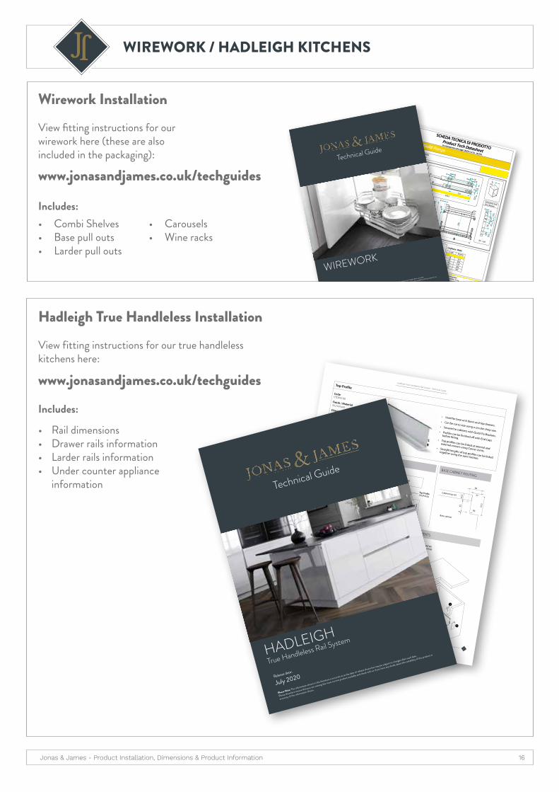
Wirework Installation View fitting instructions for our wirework here (these are also included in the packaging):
www.jonasandjames.co.uk/techguides
www.jonasandjames.co.uk/techguides
Hadleigh True Handleless Installation View fitting instructions for our true handleless kitchens here:
6
Hadleigh True Handleless Rail System - Technical Guide
Top Profile
Code VTOP4100
Finish / Material AluminiumDimensions 4100 x 56.5 x 27.2mmAccessories availableQuick Fix Brackets, code: VQFIXEnd Cap - Top, code: VTOPENDCAP
Internal Corner Joint - Top, code: VTOPINT90External Corner Joint - Top, code: VTOPEXT90
Joint Section, code: VTOPJOINT
• Used for base unit doors and top drawers.• Can be cut to size using a circular chop saw.
• Secured to cabinets with Quick Fix Brackets. • Profiles can be finished off with End Caps
before fitting.• Top profiles can be linked at internal and
external corners using Corner Joints. • Straight lengths of top profiles can be linked
together using the Joint Section.
720
150*
870*
685
27
3457.5
Worktop
Doo
r / D
raw
er F
ront
Cabinet top rail
Top Profile VTOP4100
Quick Fix Bracket VQFIX
56.5
27.2
DIMENSIONS
BASE CABINET DIMENSIONS
FITTED DETAIL
BASE CABINET ROUTING
38
27
22.5
323 R5
57.5
Base cabinet
Cabinet top rail
1. Top Profile (VTOP4100)2. Internal Corner Joint - Top (VTOPINT90)
3. External Corner Joint - Top (VTOPEXT90)
4. Quick Fix Bracket (VQFIX)5. End Cap - Top (VTOPENDCAP)
Base cabinet
BASE UNIT COMPONENTS
* nb. If installing integrated under counter appliances please increase leg height to allow for easy installation of appliance. See p. 8 for more information.
Technical Guide
Release date:
July 2020
Please Note: The information shown in this literature is accurate as at the date of release shown but may be subject to changes after such date.
Please therefore ensure that you are viewing the most current product available and check with us if you have any doubt about the suitability of the product or
accuracy of the information shown.
HADLEIGH
True Handleless Rail System
Includes:• Combi Shelves• Base pull outs • Larder pull outs
• Carousels• Wine racks
Includes:
• Rail dimensions• Drawer rails information• Larder rails information• Under counter appliance
information

Jonas & James - Product Installation, Dimensions & Product Information 17
HADLEIGH KITCHENS
Single / Double Gable Configurations(TOP VIEW)
Cabinet gable set back on ONE side to accommodate a single lateral OR intermediate profile.
Cabinet gables set back on BOTH sides to accommodate two intermediate vertical profiles.
Gableset back
Single Gable Units Double Gable Units
Single Gable units
are part of any larder
combination and are
used for either LH or RH units.
Gableset back
Gableset back
Double Gable units are used for the
middle unit/s on a larder run of 3 or 4.
LATERAL Vertical Profile (LAT)
Used with ONE unit against an end panel
INTERMEDIATE Vertical Profile (INT)
Used in between TWO single or double
gable units
Vertical Profilesfor true handleless Larders & Appliance Housing
End
Pane
l
Single Gable
Cabinet
Single Gable
Cabinet
Single Gable
Cabinet
Single Gable
Cabinet
Single Gable
Cabinet
Single Gable
Cabinet
Single Gable
Cabinet
DOUBLEGABLE
CABINET
DOUBLEGABLE
CABINET
Single Gable
Cabinet
Single Gable
Cabinet
Single Gable
Cabinet
DOUBLEGABLE
CABINET
Single Gable
Cabinet
1 LARDER 2 LARDERS 3 LARDERS
4 LARDERSOption 2 (using fewer profiles = less cost)
4 LARDERSOption 1 (for a symmetrical look)
NB: Add
35mm void to
accommodate
vertical profile.
Hadleigh Larder & Appliance Housing

Jonas & James - Product Installation, Dimensions & Product Information 18
DRAWERS
Drawer front marking tool Our drawer front marking tool is used to making installation easier & quicker.
How to use:
Tap the drawer front to create a marker indentation.
Insert the drawer markers into the drawer sides.
Attach the front fixing brackets using the markers as a guide.
Tap the drawer front to create a marker indentation.
Insert the drawer markers into the drawer sides.
Attach the front fixing brackets using the markers as a guide.
Tap the drawer front to create a marker indentation.
Insert the drawer markers into the drawer sides.
Attach the front fixing brackets using the markers as a guide.
Use code
18TOP9060
to order
6
cabi
net b
ack
43mm
350mm
350mm
21mm274mm
9mm
280mm
640mm
350mm
1350mm
350mm
1865mmpre drilled on TKC carcases
pre drilled on TKC carcases
drilling required
drilling required
drilling required
drilling required
drilling required
drilling required
cabi
net f
ront
from runnerfront edge to
cabinet front edge
drilling required
1581
mm
1590
mm
(she
lf po
sitio
n fix
ed o
n TK
C ca
rcas
es)
334m
m
464 / 564mm
Hinge holepositions
Suitable for full height doors or 1245 + 715mm doors. If using 2 doors they MUST be strapped together.
Drawer runnerpositions
Runner positioning
Nb: Please ensure that runners and soft close unit are kept clean and free from dust. When installing units, please cover runners to avoid particles entering the mechanism.
INSTALLATIONAll measurements taken from hole centre. Dimensions taken from base, using a 1970mm tall carcase.
SmartLarder View installation instructions including drawer assembly, hinge hole positions and drawer runner positions using the link below.
View SmartLarder technical guide here:www.jonasandjames.co.uk/techguides
2
Drawer runners (L/R)
Drawer sides and cover caps (L/R)
Metal back
Chipboard base
Internal brackets (L/R)
Glass sides (L/R)
Front adapters for glass (L/R)
Rear adapters for glass (L/R)
Fascia panel (1100mm lengths, cut to required length)*
Front square rails (1100mm lengths, cut to required length)**
Side rails (L/R) (Discard any unused rails)
1
2
3
4
5
6
7
8
9
10
11
PACK CONTENTS
1 x Topslide shallow boxed drawer - 83mm
4 x Topslide boxed pan drawers - 224mm
5
1
1
2
2 3
4
6
5
11
22
3
4
5
6
6
5
7
8
8
9
10
11
11
7
Drawer runners (L/R)
Drawer sides and cover caps (L/R)
Metal back
Chipboard base
Internal brackets (L/R)
Fascia panel (1100mm lengths, cut to required length)*
1
2
3
4
5
6
Fascia panel cutting dimensions: 467mm
(Internal cabinet width - 97mm)
NB. You will receive extra parts within your pack. Only the components pictured will be needed to construct your SMARTLARDER.
Any extras can either be discarded or kept as spare parts.*
** Front square rail cutting dimensions: 501mm
(Internal cabinet width - 63mm)

Jonas & James - Product Installation, Dimensions & Product Information 19
DRAWERS
Internal Drawers
Fascia Panel
Internal Bracket
Boxed Drawer
How to assemble & install:1. Cut Fascia Panel to size, see cutting dimensions
on the right.
2. Attach Internal Brackets to Fascia Panel using the supplied screws, then push into place onto the front of the boxed drawer.
3. Install the internal drawer in the cabinet like a regular drawer.
Internal drawer contents:
Internal drawer unit:(SIDE VIEW)
Fascia Panel cutting dimensions:Internal cabinet width, minus 97mm.
Eg. for 600mm wide unit, cut fascia panel to 467mm.
Closed Open
Internal drawer
160mm drawer
Cab
inet
224mm drawer
355mm (h)drawer front
355mm (h)drawer front
Internal drawer
160mm drawer
Cab
inet
224mm drawer
355mm (h)drawer front
355mm (h)drawer front
Cabinet
Internal BracketFascia Panel
Internal cabinet width
(600mm cabinet minus18mm gable ends)
eg. 467mm
eg. 564mm
1
2
Boxed Drawer (83mm height)
Fascia Panel (1100mm length, needs to be cut to size, see below)
Set of Internal Brackets (L/R)
(FRONT VIEW)
600mm (w)
Jonas & James - Product Installation, Dimensions & Product Information 20
DRAWERS
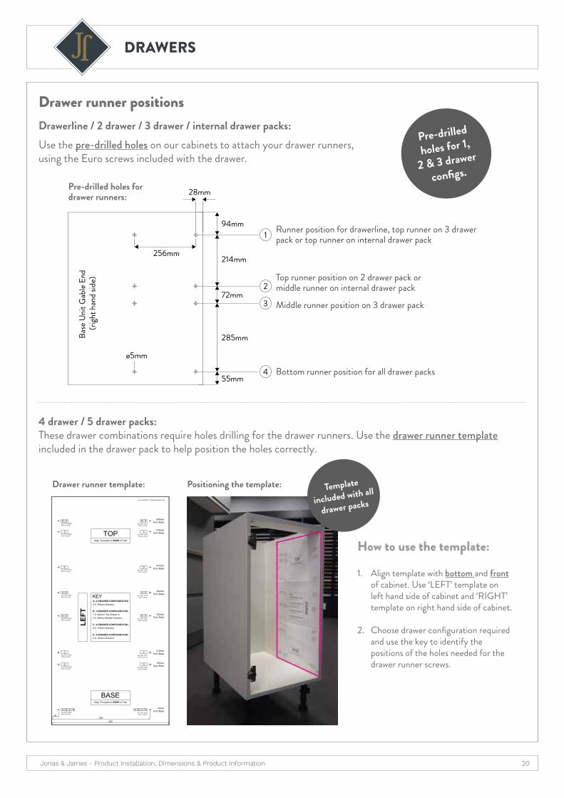
How to use the template:
Drawer runner positionsDrawerline / 2 drawer / 3 drawer / internal drawer packs:Use the pre-drilled holes on our cabinets to attach your drawer runners, using the Euro screws included with the drawer.
Middle runner position on 3 drawer pack
Bottom runner position for all drawer packs
4 drawer / 5 drawer packs: These drawer combinations require holes drilling for the drawer runners. Use the drawer runner template included in the drawer pack to help position the holes correctly.
Drawer runner template:
Pre-drilled holes for drawer runners:
Positioning the template:
1. Align template with bottom and front of cabinet. Use ‘LEFT’ template on left hand side of cabinet and ‘RIGHT’ template on right hand side of cabinet.
2. Choose drawer configuration required and use the key to identify the positions of the holes needed for the drawer runner screws.
55mm
28mm
256mm
285mm
ø5mm
72mm
214mm
Base
Uni
t Gab
le En
d (ri
ght h
and
side)
94mm1
2
3
4
Template
included with all
drawer packs
Pre-drilled
holes for 1,
2 & 3 drawer
configs.
Runner position for drawerline, top runner on 3 drawer pack or top runner on internal drawer pack
Top runner position on 2 drawer pack or middle runner on internal drawer pack