product leica infinity - zimmermann-optik.com€¦ · windows 10 leica infinity is a ... gps l1,...
TRANSCRIPT

Leica Geosystems AG Heinrich-Wild-Strasse
CH-9435 Heerbrugg Switzerland
Doc name www.leica-geosystems.com
Product Leica Infinity
Date February 18, 2016
From Kevin Hanson - Product Manager

2/13
Table of Contents 1 About this Release .................................................................................................................................................... 3 2 Installation and upgrades .......................................................................................................................................... 4 3 New Feature – GNSS Baseline Processing ............................................................................................................. 5 4 New Feature – Stake Out Applications ................................................................................................................... 11 5 New Feature – COGO Shift Rotate Scale ............................................................................................................... 11 6 Enhanced – Features and Feature Coding ........................................................................................................... 11 7 Enhanced – General Features ............................................................................................................................... 13

3/13
1 ABOUT THIS RELEASE
LEICA INFINITY 2.0
The bridge between field and office.
Infinity v2.0 brings the new GNSS Post Processing module, as well a host of important improvements and new features.
Please read this document carefully as these improvements and new features are outlined in the following chapters.
OVERVIEW:
WHAT’S NEW
GNSS Baseline Processing for single or multi frequency GNSS receiver data Baseline Analysis tool for viewing baseline quality information including residuals,
tracking and ambiguities statistics Staked Points applications – import stakeout applications from the field software COGO Shift Rotate Scale Base Maps now include ESRI World Imagery, Topo and Street maps Create or edit imported linework from field softwares Copy from CAD files to the Library for working or exporting to field softwares Improved support for imported blocks with attributes Improved support for assigning code list attributes to blocks for scaling on import Reports include more predefined data reports including data source, image points
and staked points Window Selection allows ability to delete inside or outside of defined selection Host of other general performance and usability improvements

4/13
2 INSTALLATION AND UPGRADES
INSTALLATION INFORMATION
Leica Infinity v2.0.0 Build Maintenance end date: 2576 February 16, 2016
With an active CCP the users will be able to download and install this new version. Check that the maintenance end data is on or after the date listed above. New users should download the latest version from the Leica myWorld support website.
CHECK FOR UPDATES From Help & About press Check for updates. When a new version is available you will be notified that the update can be downloaded from myWorld
OPERATING SYSTEM REQUIREMENTS
The following Microsoft® Windows™ operating system editions are supported and recommended:
Windows 7 Windows 8 Windows 10 Leica Infinity is a 32-bit and 64-bit application that automatically installs the appropriate version related to your operating system.
Note: you must have administrative privileges on your computer to successfully install Leica Infinity.
32BIT & 64BIT SUPPORT Infinity will automatically detect the Windows OS platform architecture and install the appropriate Infinity version. On a new PC the installation will detect which to install 32bit or 64bit Updates will detect 32bit or 64bit and update the current installed Infinity with the version that matches to the Windows OS platform.
MINIMUM HARDWARE REQUIREMENTS
Users who are working with project data of as example 100Mb: • Display: 1024 * 768 • Input: Keyboard and mouse with wheel • Processor: Dual-Core 1.8 GHz • RAM: 2 GB • Disk storage: 5 GB • Graphics: DirectX9 compatible with 256 MB memory
RECOMMENDED HARDWARE REQUIREMENTS
Users who are working with project data of as example >500mb typically having scan points, large numbers of panoramas or multi day GNSS observation periods: Dual Display: 1920 * 1280 Input: Keyboard and mouse with wheel Processor: Multi-Core 2.4 GHz or greater RAM: 8 GB or greater Disk storage: 500 GB or greater Graphics: Discrete graphics card, DirectX9 compatible with 2 GB memory or greater
5/13
3 NEW FEATURE – GNSS BASELINE PROCESSING
GNSS BASELINE PROCESSING OVERVIEW
GNSS baseline processing is now supported in Infinity. The new GNSS processing option brings complete multi constellation support and a simplified processing concept for deriving the most reliable and precise results from your GNSS raw data.
With the increasing availability of GNSS data it’s important to simplify the efforts for the user to work with this large set of data’s to achieve the best processing results. The user only considers: Antennas: Define the reference agency for which calibration values are
considered for processing to minimise the physical bias of GNSS antennas. Data: Define what data is passed to the processing kernel Strategy: Define how the processing kernel should mitigate sources of error
MULTI CONSTELLATION SUPPORT
Infinity fully supports all existing constellations that are useful for baseline processing. The following chart summarizes:
Constellation Signals GPS L1, L2, L5 GLONASS L1, L2 BEIDOU B2, B2 GALILEO E1, E5a, E5b, E5ab QZSS Supported
IMPORT Raw GNSS data can be imported from the following instruments: Captivate SmartWorx Viva Smartworx System 1200 RINEX 2.10, 2.11, 2.12 & 3.02
EXPORT Raw GNSS data can be exported in the standard RINEX 2.11 or 3.02 format.
3.1 PROCESSING MODULE
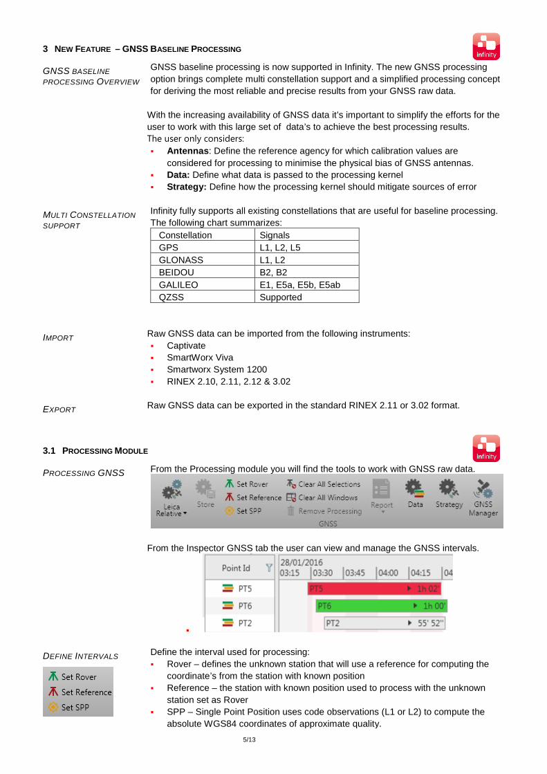
PROCESSING GNSS From the Processing module you will find the tools to work with GNSS raw data.
From the Inspector GNSS tab the user can view and manage the GNSS intervals.
DEFINE INTERVALS
Define the interval used for processing: Rover – defines the unknown station that will use a reference for computing the
coordinate’s from the station with known position Reference – the station with known position used to process with the unknown
station set as Rover SPP – Single Point Position uses code observations (L1 or L2) to compute the
absolute WGS84 coordinates of approximate quality.

6/13
To set the known position for the station used as Reference, you do this from the Property Grid. The point that will be used as the reference position is also indicated by the point role icon.
PROCESS AND STORE
Only once the intervals have been defined processing of the baselines is possible.
From the Ribbon bar the Processing button is a two mode button. The top of the button starts the processing the Antenna calibration set that is displayed. The bottom part of the button allows the user to change the calibration set if required.
Once processing has completed, the user can view the baselines in the Baseline analysis tool, run a summary or detailed report and in the end Store the baselines.
REPORTS
From the processing results two reports are available including charts: Summary – provides the short form report with processing settings and ambiguities
information. Detailed – provides the long form report with details for used and not used
observation data by epoch
SETTINGS: DATA
The data settings allow the user to set what level of data is being passed to the processing kernel. This includes the Ephemeris Type and Antenna Calibration set. It is also possible to set a specific constellation to process with or to disable a single satelitte.
SETTINGS: STRATEGY
The default Processing Strategy settings are recommended but the user can choose to manually set the solution type or solution optimization.

7/13
INTERVAL SETTINGS
To help make processing quicker there are added options to reset intervals depending on selection and windowing settings: Clear All Selections – remove all interval selections once baselines have been
processed to quickly move to defining the next Intervals Clear All Windows – remove all windows in the interval view when windowing has
been used to remove poor interval data including now SNR values, cycle slips or poor tracked status
Remove processing – when a baseline has been stored but the results were not desired its possible to remove the processing results in place of deleting any GNSS data.
GNSS MANAGER
Each project has ability to open the GNSS Manager. When you open this from inside a project, the information that is available is related only to the project.
You can copy any imported data to the Global Antenna list if required.
3.2 TOOLS – ANTENNAS & GNSS MANAGER
ANTENNAS Installed with Infinity is a set of default antenna definitions. The Antennas are organized by the organization that has provided the antenna
calibration values.
Note: Infinity uses the IGS name for all GNSS antennas and also the sensors.
Note: Removed from the list of antennas are the offsets indicating Pillar, Pole, Tripod. The offset values are written by the field sensors and imported to Infinity and called the Carrier Offset.
Note: The Leica antennas include elevation only correction values, whereas the
Geo++ antennas include both elevation and azimuth correction values.
You can toggle the view of the antennas by name or by calibration set:

8/13
GNSS MANAGER The GNSS Manager tool lets you manage related GNSS data that can be considered for the baseline processing: Import ANTEX antenna definition files Import precise ephemeris files Create a new antenna
3.3 WORKING WITH GNSS DATA
INTERVAL TIMELINE VIEW
From the Inspector you will find the views: All baselines – single view for all RTK and PP baselines Baselines sorted by reference GNSS Intervals – the time line view for viewing occupation overlap and duration GNSS results – showing the results of each processing run Intervals shows the timeline view of the GNSS observed data. Various information can be displayed including ability to turn on or off the timeline view.
Remember that with a right click on the Inspector columns the user can set the order and which columns are visible or not.
INTERVAL PROPERTIES Interval properties depend on the settings used for logging the GNSS data. Shown in Infinity are the three possible properties of the GNSS interval Static – typical observables from a stationary setup such as on tripod Moving – when the GNSS sensor has been configured to log data while the
antenna is moving such as when mounted on an automobile

9/13
Mixed – a combination of moving data and observations where the user stops to collected data with a temporary stationary setup
ANTENNA PROPERTIES The Antenna Height is shown as the combination of the user entered Height Reading and the Carrier Offset:
INTERVAL SATELLITE VIEWS
When an interval contains at least 2 epochs of observation data the interval will have the ability to expand to display the satellite observation window to view the following: Satellites – each of the satellites ordered by constellations, including cycle slips SNR – toggle to display the SNR values Elevation – toggle to indicate the elevation angle for the tracked satellite
.
INTERVAL WINDOWING
Windowing can be used to exclude data from being passed to the processing kernel. Using the mouse, the user can manage windowing.
Exclude Satellite Shift + Mouse to the Right
Include Satellite Shift + Mouse to the Left Single Satellite windowed
All Satellites windowed
RESULTS
Review the baselines and the detail information that informs for the settings used, the constellations the contributed to the solution.

10/13
You can choose from the Info & Settings to switch automatically to Results once processing has completed.
As well you can set to automatically store Phase Fixed results if desired.
BASELINES
To view the baseline residuals and satellite information, toggle the view to display the baseline analysis charts.

11/13
4 NEW FEATURE – STAKE OUT APPLICATIONS
IMPORTING STAKED POINTS
Continued focus on customers workflows now included importing and visualization of staked points from the field software. The users are made aware for the staked points by the following:
The staked points are sorted in the Navigator and Inspector from a new Point Group – Staked Points.
The graphic display includes the staked icon. Property grid includes the stored staked information
Staked Points report that lists all details from the imported applications and included:
Stake to Points Stake to Line / Arc Stake to Points & DTM
5 NEW FEATURE – COGO SHIFT ROTATE SCALE WIZARD
COGO SHIFT ROTATE & SCALE
The Shift/ Rotate/ Scale wizard enables you to transform a set of grid coordinates into new coordinates using a Classical 2D Helmert transformation for the position and a shift for the height component
6 ENHANCED – FEATURES AND FEATURE CODING
COPY FROM CAD
Field data preparation is an important workflow. With Infinity v2.0 it’s now possible to copy data from CAD design files to the project. From the Features Module, If a project has one or more CAD files imported, a user can select a copy CAD entities to the project library.

12/13
The original CAD file remains as imported and used as a visual reference.
CREATE LINES AND AREAS
From the Features Module, extended support added for creating lines and area. Also possible now to start a line with an arc or spline
EDIT LINES AND AREAS
From the Features Module, editing of imported lines and areas has been extended. Adding or removing points Converting straight to arcs or splines Splitting or joining line segments Switch the start or end direction of the line or area
IMPORTING BLOCK ATTRIBUTES FROM CAD
Blocks imported from DXF / DWG files that are part of the project Code Table now include the attributes that were defined by the user.
ATTRIBUTES MAPPED TO BLOCK ATTRIBUTES
Along with supporting the attributes defined for a block, a user can assign attributes from the code list used on the instrument to apply scale to the block. The processing of the features is made on import but can be edited from the properties if required.
13/13
7 ENHANCED – GENERAL FEATURES
ESRI WORLD BASEMAPS
Included with the existing HxIP Imagery and OpenStreeMap maps, we have added three ESRI World services – Terrain Map, Street Map and Imagery image tiles
REPORTS Additional reports added to support the workflows and reporting for project audit ability. Data Source report: Use this report directly after import for the as imported data
and then create a second data source report after making edits to the field data. Image Points report: for points that were computed from images, now there is a
separate report that includes the image information and the forward intersection values and the final computed points with codes if assigned.
Points report: added a dedicated Average Points section that outlines the measurements that contribute to the average point and the use settings.
Staked Points report: document the field staked application results for each and every measurement that was recorded in the stake points, stake to line or stake to DTM application.
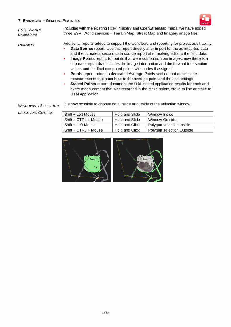
WINDOWING SELECTION
INSIDE AND OUTSIDE
It is now possible to choose data inside or outside of the selection window.
Shift + Left Mouse Hold and Slide Window Inside Shift + CTRL + Mouse Hold and Slide Window Outside Shift + Left Mouse Hold and Click Polygon selection Inside Shift + CTRL + Mouse Hold and Click Polygon selection Outside