profi driver manual e lab avrco · the contents of this user guide is copyright protected by e-lab...
TRANSCRIPT

23-Oct-2018
Profi Driver Manual
EEE---LLLAAABBB AAAVVVRRRcccooo Pascal Multi-Tasking for Single Chips
Version for
AAVVRR
© Copyright 1996-2018 by E-LAB Computers
Blaise Pascal Mathematician 1623-1662

The contents of this user guide is copyright protected by E-LAB Computers
Autor Rolf Hofmann Editor Gunter Baab
E-LAB Computers
Mikroprozessor-Technik Industrie-Elektronik Hard + Software 8-Bit · 16-Bit · 32-Bit
E-LAB Computers Grombacherstr. 27
D74906 Bad Rappenau Tel 07268/9124-0
Fax 07268/9124-24 http://www.e-lab.de
Important information Everybody tries to write Software without bugs. The emphasis is on tries, because everybody knows that the more complex a Software is, the more likely it is to produce bugs. We have the opinion, that this shouldn’t have to be norm, and that we do not have to live with the problems and mistakes (although some Software giants think like that J ). If you should find any errors, we would be thankful for any information. We will try to solve any problems as quickly as possible. It is also a normal international agreement that the software producer does not accept liability for any costs arising out of errors in software, unless otherwise agreed. E-LAB Computers do not accept liability for costs resulting out of errors in the software. It is a condition of use of this Software you agree with these terms. If you do not agree, you are not permitted to use the software. As we have said, before this exclusion of liability is international standard. This user guide and the software is intellectual property from E-LAB Computers and therefore copyright protected. This document and the software it relates to are solely for the use of the purchaser. The purchaser is not permitted to give give, sell or distribute these products. Distributing copies of these products to a third party is strictly prohibited. We like to think that you as user of the software can make money from it and therefore also expect maintenance of the product. Illegal copies would make it impossible for us to be able to maintain this service. As you see it is also in the interest of you, the user, to observe the copyright. . That´s it the author

AVRco Profi Driver
I – Table of Contents E-LAB Computers
Table of Contents
1 Introduction ................................................................................................................................................ 6
1.1 The Reason for Drivers ...................................................................................................................... 6
2 Overview ..................................................................................................................................................... 7
2.1 AVRco Versions ................................................................................................................................. 7 2.2 Driver and Manual Versions .............................................................................................................. 7 2.3 Structure of the Documentation ....................................................................................................... 7
3 Driver AVRco Profi Version ...................................................................................................................... 8
3.1 I2Cexpand_5 Driver for up to 40 bidirectional Ports ...................................................................... 8 3.1.1 Technical Data .............................................................................................................................. 9 3.1.2 Types and Functions ................................................................................................................... 10 3.1.3 Multi-Processing and TWI Port ................................................................................................... 10
3.2 SpeechPort Speech Output ............................................................................................................. 12 3.2.1 XMega und XMega-DAC ............................................................................................................ 13 3.2.2 Functions and Procedures .......................................................................................................... 14
3.3 IR RxPort InfraRed generic Treiber für RC5, NEC, Samsung etc .............................................. 15 3.3.1 Receiver ...................................................................................................................................... 15 3.3.2 Exported Types Receiver ........................................................................................................... 15 3.3.3 Exported Functions Receiver ...................................................................................................... 16
3.4 CAN driver ......................................................................................................................................... 17 3.4.1 AT90CAN32/64/128 .................................................................................................................... 18
3.4.1.1 Types and Variables ............................................................................................................... 19 3.4.1.2 Functions and Procedures ...................................................................................................... 20
3.4.2 MCP2515 .................................................................................................................................... 21 3.5 LCD Edit-Fields ................................................................................................................................. 22
3.5.1 The PCU FEdit ............................................................................................................................ 22 3.5.1.1 Constants ................................................................................................................................ 23 3.5.1.2 Types ...................................................................................................................................... 23 3.5.1.3 Procedures and Functions ...................................................................................................... 24 3.5.1.4 The Editors .............................................................................................................................. 26
3.6 LCD Graphics ................................................................................................................................... 28 3.6.1 Features of the Graphic System ................................................................................................. 28 3.6.2 Driver Implementation ................................................................................................................. 30
3.6.2.1 Controller with Linear Addressing (T6963) ............................................................................ 30 3.6.2.2 Controller with Column Addressing (HD61202, SED1531 etc) ............................................. 31 3.6.2.3 Controller with Read-Only Linear Addressing (PCF8548 etc) ............................................... 32 3.6.2.4 Color/TFT Controller ............................................................................................................... 33
3.6.3 Import of the Graphic System ..................................................................................................... 34 3.6.4 Types, Functions and Procedures .............................................................................................. 37 3.6.5 Text Display ................................................................................................................................ 45 3.6.6 Support Programs ....................................................................................................................... 47
3.6.6.1 PixCharEd.exe ........................................................................................................................ 47 3.6.6.2 BMPedit.exe ............................................................................................................................ 47
3.7 DDS10 Sinus-Triangle Synthesizer ................................................................................................ 53 3.7.1 Implementation ........................................................................................................................... 54 3.7.2 DDS10Tables .............................................................................................................................. 55 3.7.3 Types and Procedures ................................................................................................................ 55

AVRco Profi Driver
E-LAB Computers Table of Contents – II
3.7.4 XMega und XMega-DAC ............................................................................................................ 56 3.8 File System ....................................................................................................................................... 57
3.8.1 Used Definitions .......................................................................................................................... 58 3.8.2 Basics and Conventions when working with Disks, Files and the FileSystem ........................... 60 3.8.3 Exported Types, Constants and Functions ................................................................................. 61 3.8.4 Implementation ........................................................................................................................... 62 3.8.5 Disk and File Functions ............................................................................................................... 63 3.8.6 Exports of the FileSystem ........................................................................................................... 65 3.8.7 Functions of the FileSystem ........................................................................................................ 66
3.8.7.1 Basic Functions of the FileSystem .......................................................................................... 66 3.8.7.2 Maintenance Functions for Files ............................................................................................. 67 3.8.7.3 Functions for Open Files ......................................................................................................... 68 3.8.7.4 Functions for File Of String ..................................................................................................... 70
3.9 FAT16 File System (FAT16_32) ....................................................................................................... 72 3.9.1 Used Definitions .......................................................................................................................... 74 3.9.2 Basics and Conventions when working with Disks and the FileSystem ..................................... 76 3.9.3 Summary of the exported Types, Constants and Functions ....................................................... 76 3.9.4 Special Driver Implementation .................................................................................................... 81 3.9.5 Exports of the FileSystem ........................................................................................................... 81 3.9.6 Disk and Drive Functions of the FileSystem ............................................................................... 83 3.9.7 Support Functions of the FileSystem .......................................................................................... 84 3.9.8 Directory and Path Functions of the FileSystem......................................................................... 84 3.9.9 Functions for Files ....................................................................................................................... 85
3.9.9.1 Maintenance Functions for Files ............................................................................................. 85 3.9.9.2 Basic Search and Listing of Files ............................................................................................ 86 3.9.9.3 Functions for Open Files ......................................................................................................... 87 3.9.9.4 Special Functions .................................................................................................................... 90 3.9.9.5 Functions for File Of Text ........................................................................................................ 90
3.9.10 Concurrent SPI-drivers ............................................................................................................... 91 3.9.11 Example program and schematic: .............................................................................................. 92
3.10 wzNet EtherNet/InterNet Driver AVRco NetStack ......................................................................... 93 3.10.1 Architecture ................................................................................................................................. 93
3.10.1.1 Exported Types and Functions ............................................................................................... 96 3.10.1.2 Exported Variables .................................................................................................................. 97 3.10.1.3 Exported Functions and Procedures ...................................................................................... 98
3.10.2 Detailed Description of exported Types, Constants and Functions ............................................ 99 3.10.2.1 Exported Variables ................................................................................................................ 101 3.10.2.2 Exported Functions and Procedures .................................................................................... 101
3.10.3 Support Tools ............................................................................................................................ 105 3.10.3.1 TCPconf ................................................................................................................................ 105 3.10.3.2 TCPcheck .............................................................................................................................. 105
3.10.4 Telnet Server............................................................................................................................. 107 3.10.4.1 Exported Types and Functions ............................................................................................. 107
3.10.5 DNS Client ................................................................................................................................ 109 3.10.5.1 Exported Functions ............................................................................................................... 109
3.10.6 SNTP client ............................................................................................................................... 110 3.10.6.1 Exported Types and Functions ............................................................................................. 110
3.11 ModBus ASCII Serial Slave ........................................................................................................... 112 3.11.1 Introduction ............................................................................................................................... 112 3.11.2 Implementation ......................................................................................................................... 114
3.12 ModBus RTU Serial Slave ............................................................................................................. 117 3.12.1 Implementation ......................................................................................................................... 119
3.13 TINA EtherNet/InterNet Driver AVRco NetStack ......................................................................... 122 3.13.1 Architecture ............................................................................................................................... 122
3.13.1.1 Imports .................................................................................................................................. 123 3.13.1.2 Defines .................................................................................................................................. 124 3.13.1.3 Exported Types and Functions ............................................................................................. 124 3.13.1.4 Exported Variables ................................................................................................................ 125
AVRco Profi Driver
III – Table of Contents E-LAB Computers
3.13.1.5 Exported Functions and Procedures .................................................................................... 125 3.13.2 Detailed Description of exported Types, Constants and Functions .......................................... 126 3.13.3 The xUDP Protocol ................................................................................................................... 126 3.13.4 Broadcasts ................................................................................................................................ 128 3.13.5 DHCP ........................................................................................................................................ 128 3.13.6 Support Tools ............................................................................................................................ 129 3.13.7 Example Program and Schematics .......................................................................................... 129
3.14 USB Interface Introduction ............................................................................................................ 130 3.14.1 Import of the USB Driver ........................................................................................................... 131 3.14.2 Definition of the USB Driver ...................................................................................................... 131 3.14.3 Exported Types ......................................................................................................................... 131 3.14.4 Callback Function ..................................................................................................................... 132 3.14.5 Exported Functions and Procedures ........................................................................................ 132
3.14.5.1 Common Functions ............................................................................................................... 132 3.14.5.2 Simple Interface .................................................................................................................... 133 3.14.5.3 PacketDown .......................................................................................................................... 133 3.14.5.4 PacketUp ............................................................................................................................... 133 3.14.5.5 StreamDown ......................................................................................................................... 134 3.14.5.6 StreamUp .............................................................................................................................. 134
3.14.6 AVR Implementation ................................................................................................................. 135 3.14.7 Host/PC Implementation ........................................................................................................... 138
3.14.7.1 Initialisation etc...................................................................................................................... 138 3.14.7.2 Device specific ...................................................................................................................... 138 3.14.7.3 Support .................................................................................................................................. 138 3.14.7.4 Data Transfer ........................................................................................................................ 139
3.14.8 Testprogram in the IDE PED32 ................................................................................................ 140 3.14.9 Support Tools ............................................................................................................................ 141
3.15 USB-CDC Virtual Comport XMega ............................................................................................... 142 3.15.1 Import of the CDC driver ........................................................................................................... 142 3.15.2 Definitions of the CDC driver .................................................................................................... 142 3.15.3 Exported Functions ................................................................................................................... 143
3.16 AES Encrypt/Decrypt XMega ....................................................................................................... 144 3.16.1 Import of the AES driver ............................................................................................................ 144 3.16.2 Expored Functions .................................................................................................................... 144
3.17 Wiegand Interface .......................................................................................................................... 145 3.17.1 Introduction ............................................................................................................................... 145 3.17.2 Interface .................................................................................................................................... 145 3.17.3 Import of the Wiegand Driver .................................................................................................... 146 3.17.4 Defines of the Wiegand Driver .................................................................................................. 146 3.17.5 Exported Functions ................................................................................................................... 146 3.17.6 Example Program ..................................................................................................................... 146
3.18 Incremental Encoder Driver IncrPort8 ......................................................................................... 147 3.18.1 Imports ...................................................................................................................................... 147 3.18.2 Defines ...................................................................................................................................... 147 3.18.3 Functions ................................................................................................................................... 148
3.19 SLIP Driver SLIPport1..4 / SLIPportC0..F1 .................................................................................. 149 3.19.1 Imports ...................................................................................................................................... 150 3.19.2 Defines ...................................................................................................................................... 150 3.19.3 Types ........................................................................................................................................ 150 3.19.4 Vars ........................................................................................................................................... 151 3.19.5 Functions ................................................................................................................................... 151 3.19.6 SLIP Local Area Network (XMega) ........................................................................................... 156
3.19.6.1 Single-Wire Half-Duplex ........................................................................................................ 157 3.20 MIRF driver ...................................................................................................................................... 158
3.20.1 Wireless RF connection ............................................................................................................ 158 3.20.2 Channels/Frequencies of the ISM band 2.4GHz ...................................................................... 158 3.20.3 MIRF ......................................................................................................................................... 159
3.20.3.1 Tx-Power ............................................................................................................................... 159

AVRco Profi Driver
E-LAB Computers Table of Contents – IV
3.20.3.2 Topology ............................................................................................................................... 160 3.21 MIRF24port ...................................................................................................................................... 161
3.21.1 MIRF24 driver ........................................................................................................................... 162 3.21.1.1 Imports .................................................................................................................................. 162 3.21.1.2 Defines .................................................................................................................................. 162 3.21.1.3 Types .................................................................................................................................... 162 3.21.1.4 List of the Functions and Procedures ................................................................................... 163 3.21.1.5 Functions and Procedures .................................................................................................... 164
3.21.2 MIRF24 Hardware ..................................................................................................................... 166 3.21.2.1 MIRF24 Adapter for MIRF24 Modul and E-LAB EVA-Boards .............................................. 166 3.21.2.2 MIRF24 Transceiver Module ................................................................................................. 166
3.22 MIRF86port ...................................................................................................................................... 167 3.22.1 MIRF86 driver ........................................................................................................................... 167 3.22.2 MIRF86 driver ........................................................................................................................... 168
3.22.2.1 Imports .................................................................................................................................. 168 3.22.2.2 Defines .................................................................................................................................. 168 3.22.2.3 Types .................................................................................................................................... 168 3.22.2.1 Variables ............................................................................................................................... 169 3.22.2.1 List of the Functions and Procedures ................................................................................... 169 3.22.2.2 Functions and Procedures .................................................................................................... 171
3.22.3 MIRF86 Hardware ..................................................................................................................... 173 3.22.3.1 MIRF86 Adapter for MIRF86 Modul and E-LAB EVA-Boards .............................................. 173 3.22.3.2 MIRF24 Transceiver Module ................................................................................................. 173
3.23 FAT Bootloader XMega .................................................................................................................. 174 3.23.1 Bootloader Program .................................................................................................................. 175


AVRco Profi Driver
6 – Introduction E-LAB Computers
1 Introduction
1.1 The Reason for Drivers As every computer system is also a Microcontroller system it does not exist in isolation. It communicates with the outside world. This could be a human, another computer system, external media, sensors, actuators etc. There are many options. This communication can be very simple, e.g. the control of LEDs on a port. It becomes more complicated if the port is used to read mechanical switches, pushbuttons etc. With these a debouncing is indispensable. The complexity ends with graphic and filesystem drivers. All these tasks are generally done by so called drivers. The drivers are controlling the resources. In the embedded sphere these drivers were for years, even tens of years, own developments. Mostly written in assembler. The usual development systems offered at best a support for a serial interface. Because of the limited resources of the controllers this was generally sufficient. In recent years the controllers increased their performance from about 1MIPS to actually 20MIPS or more and the on-chip memory from typ. With 1kByte up to 1Mbyte is now possible to realize very complex systems with small controllers. In addition the customers demands for software grew continually. In the past some sensors, LEDs, relays and push buttons were sufficient. Nowadays control panels, LCD or even graphic LCDs, file systems and complex calculations are common demands. With a PC in mind this is no big problem. Everything is built in including all of the hardware as the necessary drivers. But even today a typical development system offers nearly nothing. In the best case one can buy libraries for a lot of money and these must frequently be adapted with lots of effort. This results frequently in “do-it-yourself” jobs and the self-made drivers are the developers “pets” that are carefully maintained. But rarely is the actual driver needed in the library. This leads again to a do-it-yourself job with extensive development and debug time consumption. For that reason the AVRco system possesses a very large number of drivers, so the programmer can focus the essentials - his application. A frequent counter argument is: „I only know my self written software exactly“ and „I do not know how a foreign driver is exactly working“. The answer is that the drivers in a development system are used hundred of times in a wide area and can essentially be considered as bug-free. Besides that, development time is expensive and can be enormously reduced by available and proofed drivers. E-LAB is proud to have the development system with the greatest number of built-in drivers. Near all drivers are supported by the AVRco Application Wizard and also by the AVRco Simulator.

AVRco Profi Driver
E-LAB Computers Overview - 7
2 Overview
2.1 AVRco Versions all AVRco Versions support all AVR Controller with an internal RAM (for the stack), that means in practice the whole range. AVRco Profi Version: the Profi Version contains all available drivers, including very complex ones like e.g. a FAT16 file system and an extensive library for graphic LCDs. The professional program development is furthermore assisted by the full support of Units. AVRco Standard Version: the Standard Version omits only the most complex drivers, and does not support units. AVRco Demo Version: the Demo Version supports all controllers and all drivers of the Standard Version. The only restriction is the limitation of the generated code to max. 4 kByte size.
2.2 Driver and Manual Versions This Manual concerns the drivers contained only in the AVRco Profi Version.
2.3 Structure of the Documentation ..\E-Lab\DOCs\DocuCompiler.pdf: contains the Pascal language description and the enhancements compared with Standard Pascal ..\E-Lab\DOCs\DocuStdDriver.pdf: contains the description of the drivers contained as well in the Standard, as in the Profi Version. ..E-Lab\DOCs\DocuProfiDriver.pdf: contains the description of the drivers contained only in the Profi Version. ..E-Lab\DOCs\DocuReference.pdf: contains a Short Reference (the the same as the online help) ..\E-Lab\DOCs\DocuTools.pdf: contains the description of the IDE, the simulator, a tutorial etc. ..\ E-LAB\IDE\DataSheets\Release-News.txt: lists the enhancements in chronological order. The enhancements are documented in the above mentioned .pdf files (DocuXXX.pdf) ..\E-Lab\AVRco\Demos\ : contains many test and demo programs
..\E-Lab\DOCs\ : contains the documentation and further schematics and data sheets

AVRco Profi Driver
8 – I2Cexpand_5 E-LAB Computers
3 Driver AVRco Profi Version
3.1 I2Cexpand_5 Driver for up to 40 bidirectional Ports Basics With some control applications and with a specific CPU used the useable IO-pins are not sufficient especially if two ports must be used for external RAM. So a larger CPU (pin count) must be used or the current port pins must be expanded with additional hardware. There are several possibilities to implement such an expansion. Real IO-chips like the 8255 often can’t be used because they need a parallel connection (at least 10bits) to the CPU and there are only 20 additional pins. Standard latches must also be connected in parallel and therefore also need many additional Pins of the CPU so the pin saving is less than expected. If the IO-speed doesn’t matter too much but the count of additional pins is high, the simple way is to implement external ports based on the I2C bus system which solve the problem very well. There are many freely programmable remote-IO port chips available for the I2C bus (TWI). The Philips chips PCA9698 are suitable very well. These contain 5 PORT-registers, 5 PIN-registers and 5 DDR-registers. So they are absolute equivalent to five AVR ports. Up to 8 devices can be connected to the bus. So upto 40 ports with upto 320 IO-pins can be implemented. Introduction to the I2Cexpander_5 This implementation either uses the software I2C-driver (I2Cport) or the internal TWI (I2C) port of the AVR mega CPUs. To use the I2Cexpander either the driver I2Cport or the driver TWImaster or the driver TWInet must be imported, the latter in Mastermode. With the XMegas one of the present TWIs must be imported: TWI_C, TWI_D, TWI_E or TWI_F As the I2C port-expander one PCA9698 from Philips must be used for 5 ports. This chip can be present up to 8 times on the I2C bus. The PCA9698 can run up to 1MBit/sec on the I2C Bus. In contrary to its predecessors the 8bit ports can be directly read, written or reprogrammed without any influence to the other parts of the chip. The base address of the PCA9698 can be placed anywhere in the I2C address area of $10..$6F with some exceptions. Because of the driver can control upto 8 Chips the user supplied adress must start with modulo 8 = $10, $18, $20 etc. The possible port names then are PORT00…PORT39, PIN00…PIN39, DDR00…DDR39. So for example for PORT00..PORT04 the I2C-addresses is $18, for PORT05..PORT09 the I2C address is $19 etc. As a specialty these I2C chips can invert the polarity of the input pins. To handle this the special ports INP_POL00..INP_POL39 are exported. A log1 inverts the corresponding input bit. The PORT, PIN and DDR registers work exactly as their counterparts in an AVR. So it is not necessary to know anything about the internas of a PCA9698. Handle them like AVR ports.

AVRco Profi Driver
E-LAB Computers I2Cexpand_5 - 9
3.1.1 Technical Data
I2C Port Software I2C imported by I2Cport or CPU-TWI imported by TWImaster or CPU-TWI imported by TWInet in Mastermode XMegas CPU-TWI imported by TWI_C, TWI_D, TWI_E or TWI_F Hardware I2C I/O-Expander chip PCA9554A from Philips, 1 piece per port I2C addresses The PCA9698 reside at the bus-addresses $10..$17 or $18..$1F etc
where PORT00..04 has the address $10, PORT05..09 has $11 etc. The PCA9698 have three address pins or bits which must be wired in a correct way. Imports As usual with the AVRco system the driver must be imported and defined. In addition the desired I2C/TWI driver must be imported and defined. Import I2Cport, I2Cexpand_5; or Import TWImaster, I2Cexpand_5; or Import TWInet, I2Cexpand_5; // use Master mode XMega Import TWI_C, I2Cexpand_5; // use TWI_C, TWI_D, TWI_E or TWI_F Defines Dependent of the I2C or TWIport, this must be defined. Example for I2Cport: Define ProcClock = 8000000; {8Mhz clock } I2Cport = PortC; {port used} I2Cdat = 7; {bit7-PortC} I2Cclk = 6, 4; {bit6-PortC, optional delay 4} I2Cexpand_5 = I2C_Soft, $10; {use Software I2Cport} I2CexpPorts_5 = Port00, Port05; {use Port00..04. and Port05..09 = 2x PCA9698} Example for TWImaster: Define ProcClock = 8000000; {8Mhz clock } TWIpresc = TWI_BR100; {100kBit/sec alt. TWI_BR400} I2Cexpand_5 = I2C_TWI, $18; {use TWIpor} I2CexpPorts_5 = Port00, Port05; {use Port00..04. and Port05..09 = 2x PCA9698} Example for TWInetMaster: Define ProcClock = 8000000; {8Mhz clock } TWInode = 05; {default address in slave mode} TWIpresc = TWI_BR400; {400kBit/sec alt. TWI_BR100} TWIframe = 4, iData; {buffer/packet size} TWIframeBC = 6; {option broadcast buffer/packet size} TWInetMode = Master; I2Cexpand_5 = I2C_TWI, $20; {use TWIport} I2CexpPorts_5 = Port00, Port05; {use Port00..04. and Port05..09 = 2x PCA9698} Example for XMega: Import TWI_C, I2Cexpand_5; // use TWI_C, TWI_D, TWI_E or TWI_F Define OSCtype = int32MHz, PLLmul=4, prescB=1, prescC=1; TWIpresc = TWI_BR100; {100kBit/sec alt. TWI_BR400} I2Cexpand_5 = TWI_C, $18; {use TWIport C} I2CexpPorts_5 = Port00, Port05; {use Port00..04. and Port05..09 = 2x PCA9698}

AVRco Profi Driver
10 – I2Cexpand_5 E-LAB Computers
I2Cexpand Requests the I2C-port to use, either software-I2C with I2C_Soft or onchip TWIport with I2C_TWI. The required basic driver must also be imported and defined. The second parameter defines the I2C-base address: $10, $18, $20, $28 etc. I2CexpPorts Defines which and how much ports must be supported. Valid defines are: Port00, Port05, Port10, Port15, Port20, Port25, Port30 and Port35 where each entry imports a group of 5 ports = 1x PCA9698.
3.1.2 Types and Functions
The import of I2Cexpand exports a special type: Type TI2CPORT = internal; This type can be used to rename a ports and give it a more relevant name. Example: Var myName[@Port00] : TI2Cport_5; Now myName can be used to access the Port00. I2CexpStat At power-up it makes sense to check the ports for a correct connection and working. To do this, the I2C-state of a port can be checked. Function I2CexpStat_5 (Port: TI2Cport_5) : boolean; This function returns a true if the select of the PCA9698 chip was successful. With the programs context such a port can be handled in the same way as a normal port of the AVR. But there are some restrictions. The port can not be addressed by pointers. It can not be a part of a construct like an array or record. It can not be procedure-local and also can not be passed as a parameter to procedures/functions. All possible operations with these ports can be seen in the example program.
3.1.3 Multi-Processing and TWI Port
In an application with Processes and/or Tasks in many cases the TWI-Bus is not only used as a network but also for other purposes (LCD, Ports etc). If then different processes access the TWI heavy conflicts are build in because such sequential drivers (I2C, TWI, UART etc) are not re-entrant, i.e. they are not interruptible and can not re-entered. Because of this the TWI port works with a semaphore of the type DeviceLock. TWI_DevLock : DEVICELOCK; TWI_DevLockTN : DEVICELOCK; // XMega TN = C, D, E or F for TWI_C…TWI_F The TWI driver observes and controls this semaphore. At the entry into the driver the semaphore is checked whether the driver is locked or not. If it is free the semaphore becomes activated (driver locked) and the job will be executed. After finishing the job the semaphore becomes released (unlocked). If the driver is locked (occupied) at entry time then a Schedule is executed and the calling Process is put into the Schedulers queue. With one of the next few schedulings this Process is restarted and again checks this semaphore. This is repeated until the semaphore becomes free (unlocked).

AVRco Profi Driver
E-LAB Computers I2Cexpand_5 - 11
Attention: Because of the cancellation of a TWI access through “Schedule“ Tasks should not use TWI accesses. A schedule completely aborts and exits a Task and so a job will not be executed if a locked semaphore is found. It is possible to set a flag if the Task executed the job successfully. If the flag is not set the Task must again be initiated to repeat this job. But this is somewhat complicated and should be avoided. Example program and schematic: an example is in the directory ..\E-Lab\AVRco\Demos\I2Cexpand_5 an XMega example is in the directory ..\E-Lab\AVRco\Demos\XMega_I2Cexpand5
schematic I2Cexpand_5
AVRco Profi Driver
12 – SpeechPort E-LAB Computers
3.2 SpeechPort Speech Output With some applications it makes sense or it is necessary to provide some informations also by a speaker. Basically if a display is out of scope or is not in the visible field. A beeper can get the users attention. But then a control field must be in operating distance. But much more sufficient to supply messages or words with speech. This is the intention of this driver. Introduction SpeechPort This driver serves for playing WAV files. The WAV files must have this format: 8bit, Mono, 11kHz For this purpose the AVRco system includes the conversion program „WAVconvert.exe“ which can be used to convert nearly any WAV files/formats into this WAV format. In order to get a clear voice the output must be done with a timer interrupt. For this purpose each AVR timer can be used if it has a Capture/Compare Unit. Sometimes this is not the case. Furthermore the interrupts are executed with short pauses between, so a CPU Clock > 8MHz is mandatory. Because these interrupts happen every 90usec each other interrupt, UART, Timer, MultiTasking handling etc. generate some distortions which can be heard as a somewhat rough replay. To avoid this it is possible to temporarily stop other operations. But with most cases this is not necessary. WAV files are large. One must expect 11kBytes of data for 1 second output. But several short messages can easily placed into the flash of a Mega128. Larger files must be stored onto an external memory. This can be an external flash, a MMC card and also TCP/IP is possible. But here the driver can not direct support these memory types. For reading and replay the data the system provides two functions, one for reading out of the internal flash and one for reading of the internal RAM. A direct reading out of any other memory is not possible. With wav contents out of an external media only the RAM mode can be used. Because the internal RAM is very limited in size a RAM-buffer must be implemented where the wav must be copied to and the driver must read from. If the wav-file is larger as this buffer a double buffered strategy must be used. Now these buffers are alternately written and read. The driver provides a READY flag which shows a true if the current buffer is completely replayed. The driver supports three different physical output modes. With the two bit-serial modes the output is either done by the AVR SPIport or by any port pin(s). The 8bit parallel output is done via any 8bit port of the CPU. A general purpose output can also be implemented by an UserDevice. The two bit-serial modes expect a serial 8bit DA-converter. The parallel port output expects an 8bit parallel DA-converter. If the UserDevice is used it gets the output data as bytes. With the bit-serial port mode the driver uses its own software-SPI port. Defining this port the first used bit of this port must be selected in the Define. This bit becomes the data bit. The next port bit becomes the clock bit and the following one becomes the select or enable bit. This line is low-active.

AVRco Profi Driver
E-LAB Computers SpeechPort - 13
Imports As usual with the AVRco system the driver must be imported and defined. The SysTick is not used. Import SpeechPort; The import of the SpeechPort automatically imports several library functions. If the output is done via SPI, the SPIdriver must be imported. But not with XMegas. Import SpeechPort, SPIdriver; XMega Import SpeechPort; Defines The driver uses an internal 8 or 16bit Timer, Timer0..Timer3, if available. Define ProcClock = 8000000; {8Mhz clock } SpeechPort = SPI; // SPIdriver must be imported and defined SPIorder = LSB; // SPI define only necessary if SpeechPort = SPI SPIpresc = 0; // presc = 0..3 -> 4/16/64/128 SPIcpol = 1; SPIcpha = 1; SPI_SS = true; // use SS pin as chipselect or SpeechPort = UserPort; // uses an user defined driver or SpeechPort = PortG, 0; // bit serial using PortG, bit0=DATA, 1=CLK, 2=SEL or SpeechPort = PortC; // 8bit parallel output on port C SpeechTimer = Timer0; // Timer0, Timer1, Timer2, Timer3 XMega SpeechTimer = Timer_C0; SpeechPort = SPI_C, SPImode3, SPImsb, PortF, 4; // Mode0..3, MSB/LSB, SS-Port, SS-Pin If the UserPort is selected as the output port so the application must also provide this driver: UserDevice SpeechIOS (b : byte); begin ... end;
3.2.1 XMega und XMega-DAC
As the output device with an XMega the internal DAC can be used: Import …, SpeechPort, DAC_B, …; … Define … DAC_B = chan01, REFextB; // DAC_B channel 0 + 1 defined SpeechTimer = Timer_D1; // use Timer_D1 SpeechPort = DAC_B1; // use DAC_B1 If the internal DAC is used then this pocedure is exported: procedure SpeechSetGain(gain : byte); // 0..4 This procedure provides a change of the gain at runtime.

AVRco Profi Driver
14 – SpeechPort E-LAB Computers
Gain 0 = Vout x0 = off Gain 1 = Vout x1 Gain 2 = Vout x2 Gain 3 = Vout x4 Gain 4 = Vout x8
3.2.2 Functions and Procedures
SpeechOutFlash This procedure replays a data block out of the Flash. The definition is: Procedure SpeechOutFlash (start : pointer; count : word); The parameter start is a pointer to the data block, count is the amount of bytes which must be processed. Attention: if the pointer points to the entry of a WAV file or this block contains the complete WAV file so an offset of 36Bytes must be used because the WAV header has this size. Then also the byte count must be decreased by 36. SpeechOutRAM This procedure replays a data block out of the RAM. The definition is: Procedure SpeechOutRAM (start : pointer; count : word); The parameter start is a pointer to the data block, count is the amount of bytes which must be processed. Attention: if the pointer points to the entry of a WAV file or this block contains the complete WAV file so an offset of 36Bytes must be used because the WAV header has this size. Then also the byte count must be decreased by 36. SpeechReady This function returns a true is the current output/replay operation is completed. Useful with double buffering. The definition is: Function SpeechReady : boolean; SpeechStop A running replay operation can be aborted with this procedure. The definition is: Procedure SpeechStop; Example program:
an example is in the directory ..\E-Lab\AVRco\Demos\Speech an XMega example is in the directory ..\E-Lab\AVRco\Demos\XMega_Speech an XMega-DAC example is in the directory ..\E-Lab\AVRco\Demos\XMega_Speech

AVRco Profi Driver
E-LAB Computers SpeechPort - 15
3.3 IR RxPort InfraRed generic driver for RC5, NEC, Samsung etc There are many ways for two units (processors, control devices etc) to communicate. If it is impossible to connect the device with cables there are only a few possibilities for communication; RF, ultrasonic and infrared link. RF must be discounted because of cost, and supersonic is very insecure. So in some cases an infrared link must be used. Infrared is relatively secure and by using a higher transmission power it is often unnecessary to have a direct line of sight between the transmitter and receiver. The reflections off the walls etc. are sufficient. The IR_RxPort driver provides an IR reveiver which supports some IR protocols, single or multiple ones which can be received as one or several in a common way: RxModes: IR_SONY, IR_SANYO, IR_NEC, IR_LG, IR_SAMSUNG, IR_RC5, IR_RC6
3.3.1 Receiver
The receiver can be connected to each input-pin. The driver uses a Timer interrupt polling scheme. With the Define the polarity of the Rx-pulse can be selected. Negative = idle value log. 1, pulse log. 0 default setting Positive = idle value log. 0, pulse log. 1 Defines for the RxPort Receiver Define IR_RxPort = PinE.0, Negative; // or Positive // RxMode: IR_SONY, IR_SANYO, IR_NEC, IR_LG, IR_SAMSUNG, IR_RC5, IR_RC6 IR_RxMode = RC5, Samsung, NEC; IR_RXLED = PortR.1, Negative; // or Positive. Define of the LED is optional // XMega IR_RxTimer = Timer_E0; // Timer_C0..Timer_F1 // AVR IR_RxTimer = Timer1; // Timer1 or Timer3 Uses uIR_Rx;
3.3.2 Exported Types Receiver
TDecodeType = (UNUSED, RC5, RC6, NEC, NEC_EXT, SONY, SAMSUNG, LG, SANYO, UNKNOWN = $FF); TDecodeRes = record DecodeType : TDecodeType; // UNKNOWN, NEC, SONY, RC5, ... Address : word; // 16bits used by Panasonic & Sharp Value : word; // Decoded value [max 16bits] Overflow : boolean; // true if IR raw code too long end;

AVRco Profi Driver
16 – SpeechPort E-LAB Computers
3.3.3 Exported Functions Receiver
Procedure IR_Start; Starts the Timer and the receiver system Procedure IR_stop; Stopps the Timer and the receiver system. Function IR_isIdle : boolean; Returns a false if a paket is currently received/processed Function IR_Decode(var Results : TDecodeRes) : boolean; If the receiver has been started and IR_isIdle returned a true then the paket can be fetched with IR_Decode. Function IR_DecodeTypeStr(Index : byte) : string[12]; The function returns the clear name oft he received frame in a string. Procedure IR_resume; After an IR_Decode the receiver must be re-enabled with IR_Resume. Attention; Some protocols return a $00 in the Address field and a $FFFF in the Value field if the same command is repeatedly send! To avoid a receiver distortion other interrupts should be short (interrupt disabled) because the Timer runs with a 50usec Timer Interrupt. The Unit „uIR_Rx“ must be imported. The Define IR_RXLED is optional and imports a LED driver portpin which flashes a LED if a frame is received. Sample program for AVR/Mega in directory ..\E-LAB\AVRco\Demos\IR_RxPort\IR_RxPortA Sample program for XMega in directory ..\E-LAB\AVRco\Demos\IR_RxPort\IR_RxPortX

AVRco Profi Driver
E-LAB Computers CAN driver - 17
3.4 CAN driver
Overview If a very fast, very secure, very reliable but cheap communication is necessary the CAN BUS is the first choice. Though Ethernet provides technical similar properties but higher speed, it is much more cost intensive and more system resources are needed. The CAN works with the approved and extremly reliable and robust RS485 differential technique which consists of two lines (twisted pairs at best) and a ground line. With this datasrates upto 1Mbit/sec are achievable, dependend on the line length. The CAN BUS is a packet (message) orientied system. This means the inherent ID address is concomitant also an information and BUS priority and is called Message Identifier. Bosch defined the CAN 2.0A format where this is called a Standard Identifier (SID) which is 11bit long. As “usable load“ there can be 0 to 8 additional data bytes. The count of bytes must be defined in the Data Length Code (DLC) field. It seems that this is very low, but because the included ID is also part of the information there are many possible combinations. With the extended CAN specs 2.0B in addition to the SID there is an Extended Identifier (EID) defined with 29 bit length, where the upper 11 bit (MSB) are overlayed with the standard SID. These Identifiers should not be interpreted as addresses. Better is a sender, object or message identifier. By the nature of the protocol it is impossible to use all values of the Identifier. So there are only 1983 values ($000-$7BF) possible out of 2048 SID ($000-$7FF). It is possible to have a pure SID or a EID CAN BUS system. With the mixed mode both formats can be used. An Identifier Extension Bitflag (IDE) decides between the two formats. For more details about the CAN BUS standard please read the “Bosch CAN 2.0 Specs“. Also a deeper look into the processor datasheet of the AT90CANxx is a good idea. So it is possible to add private function which extend this driver if necessary. There is no master or a slave, server or client. All paticipiants having equal rights and able to send or receive at every time. This naturally leads to collisions which are handled by the CAN controllers in a superior way. They are automatically resolved. The CAN BUS provides a special Arbitration, which has no timeouts compared which other collision detect implementations. Basically the message (packet) which has the highest priotity (message ID) overrides others with lower priority. But at the same time it is ensured that lower priority messages will also be processed. Based on this kind of arbitration the priority is higher if the binary value of the ID is lower. So with SID a $000 has the highest and $7FF the lowest priority. By definition SID messages have the higher priority if the 11 bit value is the same as the 11 MSB of an EID. Messages basically can be received and processed by all participiants provided that their filters accept these packets. All CAN controllers have a message filter logic which only pass the desired messages to the applcation so that the burden of the CPU can be dramatically reduced. The message ID is similar to an IP addresse but can also be valid for more than one receiver, dependend of it’s filter (mask) settings.

AVRco Profi Driver
18 – CAN driver E-LAB Computers
3.4.1 AT90CAN32/64/128
These AVR chips provide 15 so called Message Objects (MOBs) which can also be seen as mailboxes. This driver uses the BOX 0 for transmitting and the boxes 1..14 are free for receive operations. To simplify the working with the CAN BUS all receive boxes feed one PIPE (FIFO) . For transmitting there is another PIPE. The advantage of this is that the driver can fill the Rx PIPE in the background without application intervention. On the other hand the application stores it’s Tx packets into the Tx PIPE where the driver reads them sequentially and transmits them. The driver is interrupt driven. The SysTick is only necessary if the Systemtime is used. Imports As usual with the AVRco system the driver must be imported and defined. The import of CAN_AVR also imports some library functions. Import SysTick, CAN_AVR ; Defines The driver needs the size of the two PIPEs as an info and also the initial baudrate.. Define ProcClock = 16000000; // 16Mhz clock CAN_AVR = 16, 16, iData; // RxPipe, TxPipe CAN_AVRbaud = CAN_Baud125; As an option the SystemTime (Timestamp) is inserted into each received message. This timestamp can be either 16 or 32 bits. With 16 bit the SystemTime or the controller internal Timestamp counter can be used. With the SystemTime the global import of the SystemTime and also the define for the driver is necessary: From SysTick import SystemTime16; // or SystemTime32 Define CAN_AVR = 16, 16, iData, CAN_SysTime; // RxPipe, TxPipe, memory, Systemtime If the controller internal 16 bit Timestamp counter should be used this define is necessary: Define CAN_AVR = 16, 16, iData, CAN_TimeStamp; // RxPipe, TxPipe, memory, Timestamp

AVRco Profi Driver
E-LAB Computers CAN driver - 19
3.4.1.1 Types and Variables The driver exports some type declarations which must be used in the communication. type
tAVR_CAN_Flag = (CAN_AERR, CAN_FERR, CAN_CERR, CAN_SERR,CAN_BERR, CAN_RTR, CAN_IDE, CAN_DLCW); tAVR_CAN_Flags = BitSet of tAVR_CAN_Flag; tCANMessage = record
MOBIdx : byte; // Message Object = Rx Mailboxnumber EID : longword; // Extended Identifier ~ Accept mask 29 bits SID [@EID] : word; // Standard Identifier ~ Accept mask 11bits as Overlay TimeStamp : word|longword; // optional, only if CAN_TimeStamp or CAN_SysTime is defined Flags : tAVR_CAN_Flags; // Statusflags of the Mailbox DLC : byte; // data length 0..8 data : array[0..7] of byte;
end;
tCAN_baud = (CAN_Baud25, CAN_Baud50, CAN_Baud100, CAN_Baud125, CAN_Baud200, CAN_Baud250, CAN_Baud500, CAN_Baud1000);
tAVR_CAN_Stat = (CAN_ACKError, CAN_FrameError, CAN_CRCError, CAN_StuffError,
CAN_BitError, CAN_RxOK, CAN_TxOK, CAN_DLCwarn); tAVR_CAN_States = BitSet of tAVR_CAN_Stat;
var
CAN_RxPipe: Pipe [defined] of tCANMessage; CAN_TxPipe: Pipe [defined] of tCANMessage; CAN_RejectFlags : tAVR_CAN_States;
This variable serves to control the reception of messages in case there was a receive error. If such an error occurs and the corresponding bit is set in this bitset the message is ignored and never placed into the RX Pipe. Normally all received messages having the fRXOK flag active, are placed into RX pipe and it is the job of the application to interprete the included status flags, eg. ignore such a message. Example:
CAN_RejectFlags := [CAN_Frameerror, CAN_CRCError]; Ignores messages with a Frame or CRC error. Details about the error types and their meaning can be found in the CAN 2.0 specs and the AVR datasheet.

AVRco Profi Driver
20 – CAN driver E-LAB Computers
3.4.1.2 Functions and Procedures function AVR_CAN_Init (RxMObCount : Byte) : boolean; The following operations are executed: The CAN hardware is completely reset and initialized. All mailboxes are emptied and initialized. RxMObCount (1..14) defines the count of the Rx mailboxes. Both pipes are emptied and initialized. CAN_RejectFlags is set to []. CANTCON is set to 255 to get the lowest internal Timestamp frequency. The AVR_CAN_Enable function is called before enabling the CAN interrupts. With this driver the result is always true. procedure AVR_CAN_Disable; Disables the driver so that the application can change the baudrate, the masks etc.. procedure AVR_CAN_Enable; Re-enables the driver after a disable. function AVR_CAN_BaudRate(br : tCAN_baud) : boolean; Sets the baudrate. A Disable should precede and after it there must be an Enable. function AVR_CAN_SetRxMask (yMBox: byte; wIDTag, wIDMask: word) : Boolean; Sets the standard ID-TAG and the ID-Mask for a Rx-Box (1..14). Both parameters together define whether a message must be accepted by this box or not. The condition is: (RxMsg.SID and wIDMask) = (wIDTag and wIDMask). function AVR_CAN_SetRxEMask (yMBox: byte; lwIDTag, lwIDMask: longword) : Boolean; Sets the extended ID-TAG and the ID-Mask for a Rx-Box (1..14). Both parameters together define whether a message must be accepted by this box or not. The condition is: (RxMsg.EID and lwIDMask) = (lwIDTag and lwIDMask). function AVR_Can_GetError(box : byte) : boolean; Checks the actual state of this Box for errors. function AVR_Can_GetStatus(box : byte) : tAVR_CAN_States; Returns the actual state of this Box. function AVR_CAN_RxErrCount : byte; Returns the Rx Error Count. Each Rx error increments this value, each valid reception decrements it. function AVR_CAN_TxErrCount : byte; Returns the Tx Error Count. Each Tx error increments this value, each valid transmit decrements it. procedure AVR_CAN_StartMessage; If one or more messages are written into the Tx-Pipe by “PipeSend(CAN_TxPipe, Msg)“ this procedure must be called in order to start the transmission for one message. Sending all messages in a pipe this must be done in a loop: while PipeStat(CAN_TxPipe) <> 0 do AVR_CAN_StartMessage; endwhile; Example programs in the directory ..\E-Lab\AVRco\Demos\CAN_AVR
AVR CAN128M and AVR CAN128S

AVRco Profi Driver
E-LAB Computers CAN driver - 21
3.4.2 MCP2515

AVRco Profi Driver
22 – LCD Edit E-LAB Computers
3.5 LCD Edit-Fields by U.Purwin Overview With uP systems, in many cases some values must be creatable, selectable and editable by the user. Often only a small alpha numeric LCD and some keys or buttons are available to do this. The main problem then is to supply some good edit functions, to recognize wrong user entries and possibly discard them. Furthermore upper and lower limits must be observed by these editors. So handling and editing of values (human interface) is not a simple task. The implementation of the editor introduced here allows to work with any LCD and nearly any kind of user input devices. The application passes a value to the driver/editor and then the selected editor displays it on the LCD. An essential part of the editors is the KeyBoard Handler. This is a Callback function within the editor which calls the basic keyboard read and process routine in the application. Before the first call of an editor the address of the keyboard handler must be passed to the Unit so that the editors are able to make a callback to it. The editor Unit "FEdit" contains all necessary edit functions and responds to events found in the keyboard handler. Only when the keyboard handler returns the key “EdKeyExit“ then the current edit function gets terminated and returns to the application with the result of this editor. This Unit contains powerful and comprehensive functions to display and edit of Strings, Boolean, Bytes, Words, Integer, Longword, LongInt, ListFields, Time, Date and IP-addresses. The editors are fully controllable by parameters and are protected against false usage by the user. The included editors work together with the standard LCD driver and also with the LCD-Multiport driver of the AVRco system. Imports The Unit "FEdit" must be imported with Uses FEdit;
3.5.1 The PCU FEdit
The system provides the Unit FEdit in the form of a precompiled Unit (PCU). Units which are part of the system reside in the search path of the compiler in the directory "System". In contrary to the pure system imports which are imported by the "Import" clause (e.g. "LCDport") these system Units must be imported as all other Units with "Uses". Because of this they are only accessible with the Profi version of AVRco. These Units contain all implemented functions, but are processed at compile time by the AVRco Smartlinker. This means that only these functions which are used by the application will generate machine code and use code space. So it’s clear that the program size will not be increased in an unnecessary way. Defines and Imports The Unit automatically checks the Imports and Defines of the relevant system parts. Example : If LongInt or LongWord is not imported the edit functions EdLongInt or EdLongWord are not useable.

AVRco Profi Driver
E-LAB Computers LCD Edit - 23
3.5.1.1 Constants Absolute Constants These constants are fixed and can not be changed: EdEditLength : Byte = 40 Defines max. count of characters of an edit field.
EdLabelLength : Byte = 20 Defines max. count of characters of a label field. EdTimeDelim : Char = ':' Delimiter for time edit fields. EdDateDelim : Char = '.' Delimiter for date edit fields. EdIPDelim : Char = '.' Delimiter for IP edit fields. Structured Constants These constants are predefined but can always be changed/overwritten at runtime. EdPreClearLine : Boolean = True If true the entire concerning LCD line will be cleared before the first access. EdBooleanTrue : String = ' AN' Default display string for “true“ with boolean edit fields EdBooleanFalse : String = 'AUS' Default display string for “false“ with boolean edit fields
KBRepeatTrigger : Byte = 100; // in SysTicks This value (constant x SysTick) defines the time after a pressed UP-or DOWN key starts the AutoRepeat operation. KBRepeatDelay : Word = 100; // in SysTicks This value (constant x SysTick) defines the speed of the AutoRepeat
3.5.1.2 Types Type tEdArrayLocation = (edRam, edEEProm, edFlash); Source of the array for the list editor for EDArray Type tEdLCDType = (edLCDnone, EdLCDStandard, EdLCDMulti); Type of the LCD-Display which an editor must use. Default edLCDnone. Type tEdKeys = (EdKeyNone, EdKeyUP, EdKeyDown, EdKeyLeft, EdKeyRight, EdKeyExit); Key names for the editors. Must be used by the Callback-function tEDKeyBoardHandler Type TEdActEditor = (edNoneEd, edTimeEd, edDateEd, edByteEd, edBooleanEd, edStringEd,
edIntegerEd, edIPAddressEd, edLongIntEd, edWordEd, edLongWordEd, edListEd);
Enumeration for the installation of the Keyboard and the Error handler. The error and event handler returns the current edit action to notify the application. Type tEdErrorEvent = (edLeftLim, edRightLim, edUPLim, edDownLim, edNoKeyHandler,
edNoLCDDefined); Possible error and event types passed to the optional ErrorHandler Callback function. Type tEdKeyBoardHandler = Function (ActiveEditor : tEdActEditor; LookKey : tEdKeys) : tEdKeys;

AVRco Profi Driver
24 – LCD Edit E-LAB Computers
Template of the Callback function KeyHandler Type tEdErrorEventHandler = Procedure (ActiveEditor : tEdActEditor; ErrorEvent : tEdErrorEvent); Template for the optional Callback function for the event and error handling in the application. Type tEdIPAddress = Record IPOct1, IPOct2, IPOct3, IPOct4 : byte; end; Record type which must be used for passing IP-addresses to and from the editor function EdIPAddress. Contains the four address bytes of an IP-address.
3.5.1.3 Procedures and Functions Common Support Functions These functions are often used for converting common formats into strings and vice versa. They don’t use either any display nor need any Keyboard Handler. The time strings must have the format hh:mm:ss The date strings must have the format dd.mm.yyyy Function TimeBytesToTimeString (Hour, Minute, Second : Byte) : string[8]; Converts the bytes of a RTC into a formatted time string. Procedure TimeStringToTimeBytes (TimeString : string[8]; var Hour, Minute, Second : byte); Converts a formatted time string into the bytes for a RTC usage. Function DateBytesToDateString (Day, Month, Year : Byte) : string[10]; Converts the bytes of a RTC into a formatted date string. Procedure DateStringToDateBytes (TimeString : string[10]; var Hour, Minute, Second : byte); Converts a formatted date string into the bytes for a RTC usage. Support Functions for the Editors These functions control the behavior of the editors. The display type and with the Multi-LCD the display number can be changed at runtime. Procedure EdSetLCDType (LCDType : tEdLCDType); Selects the LCD type which must be used by the editors. edLCDStandard or edLCDMulti. Procedure EdSetMultiLCDNum (Num : TLCD_num); Selects the LCD_NUM with MultiLCDs Procedure EdSetKeyBoardHandler (ActiveEditor : tEdActEditor; KeyHandler : tEdKeyBoardHandler); Defines the current keyboard handler for the editors. It’s possible to have several keyboard handler which can be exchanged at runtime. These handlers must consist of a predefined structure. Keyboard handler : Function MyKeyHandler (ActiveEditor : tEdActEditor; ReturnKey : tEDKeys) : tEDKeys; begin case ActiveEditor of EdTimeEd : ... | EdDateEd : ... | endcase;

AVRco Profi Driver
E-LAB Computers LCD Edit - 25
if INP_STABLE_G (LEFT) then Return(EdKeyLeft); endif; if INP_STABLE_G(RIGHT) then return(EdKeyRIGHT); endif; ... end; // Main begin ... EdSetKeyBoardHandler (@MyKeyHandler); ... end. Procedure EdSetErrorEventHandler (ActiveEditor : tEdActEditor; ErrorEventHandler : tEdErrorEventHandler); Defines the optional error and event handler. Possible events are the crossing of the limits by the four keys UP, DOWN, LEFT and RIGHT. Possible errors are: no Keyboard Handler specified or no LCDtyp specified. The handler must consist of a predefined structure. Error handler: Procedure MyErrorEventHandler (ActiveEditor : tEdActEditor; ErrorCode: tEdErrorEvent); begin case ActiveEditor of EdTimeEd : ... | EdDateEd : ... | endcase; case ErrorCode of EdLeftLim: //Left Limit | EdRightLim: //Right Limit | EdUPLim: //Up Limit | EDDownLim: //Down Limit | EDNoKeyHandler: //No KeyHandler found | EDNoLCDDefined: //No LCD-Display Defined | endcase; end; // Main begin ... EdSetErrorEventHandler(@MyErrorEventHandler); ... end.

AVRco Profi Driver
26 – LCD Edit E-LAB Computers
3.5.1.4 The Editors Most of the editors have standard parameters described below. Additional parameters are needed in some editors. Furthermore all functions are contained in the demo program ..\E-Lab\AVRco\Demos\LCD_Edit\LCDEdit parameter description EdValue editable parameter passed to the editor LeadLabel optional leading label of the edit field Postlabel optional trailing label after the edit field e.g.
LeadLabel-> Masse: 12.54 kg <- PostLabel ^- EdValue X, Y Position line/column on the LCD display BlinkCursor Blinking block cursor on the LCD display at the edit position VMin,VMax Minimum and maximum possible edit value Repeater AutoRepeater on/off in the string and list editor Decimal Visible decimal count of the edit value Function EdTime (EdValue : string[EdTimeLength]; LeadLabel : string[EdLabelLength]; X, Y : byte; BlinkCursor : boolean; EditSeconds : Boolean) : string[EdTimeLength];
EditSeconds defines whether the seconds can be edited Function EdDate (EdValue : string[EdDateLength]; LeadLabel : string[EdLabelLength]; X, Y : byte; BlinkCursor : boolean) : string[EdDateLength]; Function EdByte (EdValue : byte; LeadLabel, PostLabel : string[EdLabelLength]; X, Y : byte; BlinkCursor : boolean; VMin, VMax : byte) : byte; Function EdBoolean (EdValue : boolean; LeadLabel, PostLabel : string[EdLabelLength]; X, Y : byte; BlinkCursor : boolean) : boolean; Function EdString (EdValue : string[EdStringLength]; LeadLabel, PostLabel : string[EdLabelLength]; X, Y : byte; BlinkCursor : boolean; MaxLen : Byte; MinChar, MaxChar : byte; Repeater : boolean) : string[EdStringLength]; MaxLen defines the maximum string length which can be edited Function EdInteger (EdValue : integer; LeadLabel, PostLabel : string[EdLabelLength]; X, Y : byte; BlinkCursor : boolean; VMin, VMax : integer; Decimal : byte) : integer; Function EdLongInt (EdValue : longint; LeadLabel, PostLabel :string[EdLabelLength]; X, Y : byte; BlinkCursor : boolean; VMin, VMax :longint; Decimal : byte) : longint; Function EdWord (EdValue : word; LeadLabel, PostLabel : string[EdLabelLength]; X, Y : byte; BlinkCursor : boolean; VMin, VMax : word; Decimal : byte) : word; Function EdLongWord (EdValue : longword; LeadLabel, PostLabel : string[EdLabelLength]; X, Y : byte; BlinkCursor : boolean; VMin, VMax : longword; Decimal : byte) : longword;

AVRco Profi Driver
E-LAB Computers LCD Edit - 27
Function EdList (EdValue : pointer; Location : tEdArrayLocation; LeadLabel, PostLabel : string[EdLabelLength]; X, Y : byte; BlinkCursor : boolean; StrLen, Count, Default : byte) : byte; EdValue is a pointer to an array of strings (see the demo program) Location defines the source (RAM, ROM, EEPROM) of the array StrLen defines the maximum length of a string in the array (Be careful here. Pointers are used) Count defines the entry count of the array (Be careful here. Pointers are used) This editor serves to display string lists and supports the up and down stepping in the list/array. On exit the selected index is returned. Please note that the array must start with the index 0. Function EdIPAddress (EdValue : tEdIPAddress; LeadLabel, PostLabel : string[EdLabelLength]; X, Y : byte; BlinkCursor : boolean; IPMin, IPMax : tEdIpAddress) : tEdIPAddress; This editor serves for the (non trivial) editing of IP-addresses in the Ethernet area. Example program:
an example is in the directory ..\E-Lab\AVRco\Demos\LCD_Edit Attention with the Demo and Standard version of AVRco Don’t recompile the demo program, but simply load it with the Simulator and check it out.

AVRco Profi Driver
28 – LCD Graphics E-LAB Computers
3.6 LCD Graphics Overview The interaction between a human and a machine becomes more and more complex but also more sophisticated. Years ago a button, a switch and a few LEDs were sufficient, but today multi row LCD displays and foil keyboards are a normal interface. Because of the power of today’s processors, their relative large embedded memory and the availability of intelligent and inexpensive Graphic LCDs the trend goes to graphical user interface. Take a look at handys, palmtops etc. For the end user, the client and also for the developer a little „Windows“ can be an enticing thing. But one must keep in mind that we don’t have a Pentium processor and no high power graphic engine. The current implementation therefore is limited to LCDs with a resolution up to 1024x1024 pixels. But this values are theoretical. In the real world, at least with erasing the whole screen, each pixels must be accessed and this consumes a huge amount of CPU power and time. The necessary CPU time raises in quadrate with the resolution of the LCD. 128x128 = 16384 Pixels. 1024x1024 = 1048576 Pixels. Handy display sizes are 128x64, 128x128, 240x128, 320x240 and maybe 640x480. When selecting a LCD display there are 2 types: intelligent with build-in controller (i.e. Toshiba T6963C) and „stupid“ without a controller. With a low volume production the types with controllers should be preferred, because implementing an own controller on board is not simple. With a volume of 100 and more it can be the better and cheaper way to put the controller onto the CPU board (e.g. Seiko/Epson SED1xxxx). When selecting a LCD controller take in mind that the more powerful a controller is, the more complex the design of the software interface is. PC graphic chips are not useful. The controller only must support a byte-wise access to the display’s refresh RAM. A controller-internal conversion of x/y-coordinates to linear addresses is not necessary. But the actual color graphic LCDs mostly have an internal xy-addressing, so the xy-address mode must then be used here. With color LCDs many of the driver functions have changed to support colors.
3.6.1 Features of the Graphic System
Obviously you are working with Windows®. So you have an opinion and a feeling what a window is J The AVRco implementation also uses windows. Because these windows differ in complexity and power from the windows of Windows®, the term window is not used here but the term ViewPort. A ViewPort doesn’t have a visible frame, it can’t be simply resized or moved. There is no window hirarchy which means that in whole or in parts overlayed windows are not protected among them but they overwrite themselves mutual. These drawbacks are essential if you compare to Windows®. The implementation of this additional features explodes a mega103. A todays Windows® implementation fills a CD-ROMJ . That’s about the disadvantages of the implemented ViewPorts. But fortunately there also some advantages. ViewPort physical A ViewPort defines a part of the LCD display. The position and physical size of the ViewPort must be determined by the function OpenView. ViewPort logical A logical coordinate system can be attached to the ViewPort by the function ScaleView. All draw and string operations use this coordinate system for their positionings. The dimension range is a 16bit integer. A scaling of the ViewPorts 0 is not possible.

AVRco Profi Driver
E-LAB Computers LCD Graphics - 29
ViewPort Attributes Each ViewPort has an own set of attributes for strings and common draw operations. These attributes define for example how a line has to be drawn, with XOR, OR or NOR. ViewPort Clipping All write operations into a ViewPort are checked against the ViewPorts borders. If some pixels are outside of the ViewPort, the drawing is cancelled at this point and will be continued if the drawing again is inside the border (example: circles). ViewPort Select If there are a few ViewPorts defined, one can switch between them with SwitchView. All following operations are now related to this port with it’s attributes and scalings. ViewPort Save/Restore If there is sufficient memory and CPU power, it’s possible to save the content of a ViewPort with SaveView before it will be destroyed by another, overlapping ViewPort. Later this content can be restored from memory by RestoreView. This makes only sense with small displays or small ViewPorts. ViewPort Visuality It’s possible to visibly show the borders of a ViewPort with the function FrameView. This frame is write protected within the ViewPort. ViewPort Definition To clarify the physical and logical coordinates of a ViewPort a litte graphic:
Example LCD 320x240: GOpenView (1, 120, 120, 220, 220) opens a square sized ViewPort 1 with the size of 100x100 pixels. The origin of the ViewPort is the point 120, 120 of the display.
GScaleView (1, -1000, 1000, 1000, -1000) scales the ViewPort 1 and defines the internal scalings of the selected ViewPort, where Xs, Ys defines the top-left corner and Xe, Ye the bottom-right corner of the logical ViewPort.
0x 0y 120x 120y 220x 220y
-1000x +1000y 0x
0y +1000x -1000y
319x 239y

AVRco Profi Driver
30 – LCD Graphics E-LAB Computers
3.6.2 Driver Implementation
The AVRco system provides a complete and powerful range of high-level graphic functions. These functions are internal reduced to simple byte-read-write functions. These accesses to the display refresh RAM must be provided by the programmer himself. For this purpose the system exports a so called UserDevice Function named GraphIOS. This routine must be implemented by the programmer. The system passes commands, addresses and parameters which the programmer must work on so that they can be passed to the displays’s controller.
3.6.2.1 Controller with Linear Addressing (T6963) The system passes 4 parameters (5 if color is imported) to the function GraphIOS and expects either a byte or a boolean as the result. The first parameter (byte) defines what to do, the second (word) defines the display address of a byte, where the display is recognized as a linear memory of bytes. The last two parameters can be used alternatively. In many cases the parameter „Mask“ is used. It can mask (manipulate) a single bit (pixel) within the addressed byte. If the used controller supports single bit access (pixel manipulation), the parameter „pixel“ can be used for this. Remarks:
1. Because the address parameter is of the size word, the actual resolution of the display is limited to 65536 bytes = 524288 pixels, which results in a maximum display size of 724x724 pixels. 2. Some controller resp. intelligent displays support different addressings respective byte-accesses to the
display RAM. It distinguishes between 5 and 8 bits for a byte. Avoid these modes which don’t support the full 8bits per access/byte. The CPU-time to compute an address of a byte and the related mask will be increased drastically with non-8bit modes
If the color option was imported the UserDevice receives an additional byte color. This byte then must me interpreted by the application in a proper way. UserDevice GraphIOS (cmd : byte; adr : word; mask, pixel, color : byte) : byte; UserDevice GraphIOS (cmd : byte; adr : word; mask, pixel : byte) : byte; begin // commands passed to user defined function "GraphIOS" // 0 display init adr = none mask = none pixel = none [color = none] result = none // 1 display clear adr = fillpatt mask = none pixel = none [color = none] result = bool // 2 write byte adr = byte adr mask = byte pixel = mode [color = byte] result = none // 3 read byte adr = byte adr mask = none pixel = none [color = none] result = byte // 4 set pixel adr = byte adr mask = mask pixel = pixel [color = byte] result = none // 5 clear pixel adr = byte adr mask = mask pixel = pixel [color = byte] result = none // 6 xor pixel adr = byte adr mask = mask pixel = pixel [color = byte] result = none case cmd of 0 : cmd:= 0; | // display init 1 : cmd:= 1; | // display clear 2 : cmd:= 2; | // write byte with attributes 3 : cmd:= 3; | // read byte 4 : cmd:= 4; | // set pixel 5 : cmd:= 5; | // clear pixel 6 : cmd:= 6; | // xor pixel endcase; return(cmd); end;
AVRco Profi Driver
E-LAB Computers LCD Graphics - 31
CMD 0 Display Init Serves to initialize of some hardware, for example ports and the controller of the LCD The result is meaningless. CMD 1 Display Clear Erases the display. If the controller has a build-in erase function, it should be invoked. In this case the result must be “true“. If the controller doesn’t support it, the result must be „false“. Then an internal erase loop will be called, which naturally takes a long time. It’s also possible to write an own erase routine in assembler and return a “true“ to tell the system that the erase was successful terminated CMD 2 Write Byte Writes the byte passed in the parameter “Mask“ into the display RAM to the location “Adr“. The parameter „Pixel“ contains a write attribute. A „0“ means that the byte „Mask“ must be inverted before passing it to the controller. If „Pixel“ is a „1“ the byte „Mask“ has to be written without any changes to the controller. With a „2“ the byte at the location „Adr“ must be read from the controller and then XORed with „Mask“. The result then must be written to the controller to the location „Adr“. CMD 3 Read Byte Reads the byte at the location “Adr“ from the display RAM and returns it as the result. CMD 4 Set Pixel Reads the byte at the location “Adr“ from the display RAM, activates the bit/pixel defined by “Mask“ and stores the changed byte into the display RAM. (Read-Modify-Write) If the controller supports pixel-manipulation, so the read can be omitted. Only the byte address “Adr“, the pixel address (parameter “pixel“) and the corresponding command must be passed to the controller. CMD 5 Clear Pixel Reads the byte at the location “Adr“ from the display RAM, resets the bit/pixel defined by “Mask“ and stores the changed byte into the display RAM. (Read-Modify-Write) If the controller supports pixel-manipulation, so the read can be omitted. Only the byte address “Adr“, the pixel address (parameter “pixel“) and the corresponding command must be passed to the controller. CMD 6 Xor Pixel Reads the byte at the location “Adr“ from the display RAM, inverts the bit/pixel defined by “Mask“ and stores the changed byte into the display RAM. (Read-Modify-Write) If the controller supports pixel-manipulation, so the read can be omitted. Only the byte address “Adr“, the pixel address (parameter “pixel“) and the corresponding command must be passed to the controller. Example Program: an example is in the directory ..\E-Lab\AVRco\Demos\GraphLCD
3.6.2.2 Controller with Column Addressing (HD61202, SED1531 etc) The system passes 2 parameters to the function GraphIOS. No result is expected. The first parameter (byte) defines what to do, the second (byte) defines either a display row address or a data byte to write. The driver always writes into it’s internal RAM. A display update is only done on demand by “gDispRefresh“ where always the whole display content is rewritten.

AVRco Profi Driver
32 – LCD Graphics E-LAB Computers
Remarks: 1. Because a fast converting algorithm is used a display update lasts about 25mSec at 16MHz in serial mode and 17msec in parallel mode. 2. This algorithm restricts the horizontal and vertical resolution to a multiple of 8 (32x64 64x128). Values between that are possible. Imports This mode is imported with Define LCDgraphMode = column, iData; {column mode controller} UserDevice GraphIOS (cmd : byte; data : byte); begin // commands passed to user defined function "GraphIOS" // cmd 0 set row address data = row // cmd 1 write data byte data = content if cmd = 0 then // set row addr = data else // write data byte endif; end; CMD 0 Set row address The data byte must be passed to the controller as a new row address. The controller increments this value after each data write access. So only once this command appears for one display line. CMD 1 Write display data The user program must write the data byte into the data register of the controller. Example programs:
an example of a SED1531 implementation is in the directory ..\E-Lab\AVRco\Demos\LCD_1531 an example of a HD61202 implementation is in the directory ..\E-Lab\AVRco\Demos\LCD_61202
3.6.2.3 Controller with Read-Only Linear Addressing (PCF8548 etc) This mode is very similar to the column addressing mode, except that a linear addressing of the display refresh memory is possible here. But these controllers also do not support the read back of the graphic memory so always the entire screen memory must be rewritten. The system passes 2 parameters to the function GraphIOS. No result is expected. The first parameter (byte) defines what to do, the second (byte) defines either a display row address or a data byte to write. The driver always writes into it’s internal RAM. A display update is only done on demand by “gDispRefresh“ where always the whole display content is rewritten. Remarks: 1. Because a fast converting algorithm is used a display update lasts about 25mSec at 16MHz in serial mode and 17msec in parallel mode. 2. This algorithm restricts the horizontal and vertical resolution to a multiple of 8 (32x64 64x128). Values between that are possible.

AVRco Profi Driver
E-LAB Computers LCD Graphics - 33
Imports This mode is imported with Define LCDgraphMode = readonly, iData; {linear, readonly controller} UserDevice GraphIOS (cmd : byte; data : byte); begin // commands passed to user defined function "GraphIOS" // cmd 0 set row address data = row // cmd 1 write data byte data = content if cmd = 0 then // set row addr = data else // write data byte endif; end; CMD 0 Set row address The data byte must be passed to the controller as a new row address. The controller increments this value after each data write access. So only once this command appears for one display line. CMD 1 Write display data The user program must write the data byte into the data register of the controller.
3.6.2.4 Color/TFT Controller All low-cost color TFT LCDs provide an internal controller which supports the xy-addressing. This means for example that pixels can be accessed with their real xy-address. Also horizontal and vertical lines. Also area fills are supported. This simplifies the underlying driver drastically. But the read-back oft he graphic memory is not possible with most displays and also an XOR operation doesn’t make sense with colors. Here most of the driver functions are extended for colors and the operations are somewhat different to black and white. With small displays the SPI interface is used where a 16MHz SPI clock isn’t any problem and the operation speed is sufficient fast. This modus must be imported by: From LCDGraphic import GraphColor; Define LCDgraphMode = XYaddress, iData; // colored xy-address mode This xy-address mode then exports this enumeration: // gDrawType = (dtPixel, dtLineX, dtLineY, dtFillRect, dtClear); UserDevice GraphIOS(xs, ys, xe, ye : word; pattern, colorFg, colorBg : byte; draw : gDrawType) : byte; begin case draw of dtClear : // FillScreen | dtFillRect : // FillRect | dtLineX : // draw line horizontal | dtLineY : // draw vertical line | dtPixel : // draw one pixel | endcase; return(0); end;

AVRco Profi Driver
34 – LCD Graphics E-LAB Computers
3.6.3 Import of the Graphic System
As usual with the AVRco system devices must be imported and defined. Imports Import SysTick, LCDGraphic, ...; // only necessary if strings are used -> From LCDGraphic Import CharSet; {block CharSet, pixels} From LCDGraphic Import GraphColor; {simple color support, only in linear mode} Defines The following define directives specify the LCD-Graphic-System: Define LCDGraphic = 240, 128, 8; {x-pix, y-pix, accesswidth} GViewports = 4, iData; {logical ViewPorts, scalings} LCDgraphMode = linear, iData; {optional, linear is default} or LCDgraphMode = column, iData; {column oriented controller} or LCDgraphMode = readonly, iData; {linear, readonly controller} or LCDgraphMode = xyAddress, iData; {col or xy-address controller} or DefCharSet = 'Graphchars.pchr'; {FileName, stored into Flash} or DefCharSet = RAM; {charset is stored into RAM} TGraphStr = 20; {Graphic Text String Length, max 24} These 2 defines are “must“ definitions. LCDgraphic defines the display-size (x, y) and the access width (normally 8). GViewPorts defines the count of the logical ViewPorts (windows) and the memory area for their parameters . If CharSet is imported these two definitions must be done: DefCharSet defines the default character set which should be used for string drawings in all ViewPorts If a filename in ’’ is present, all charset are expected to reside in ROM/Flash. If the parameter „RAM“ is given the system expects that all char sets reside in the RAM. TGraphStr defines the string type resp. it’s maximal length which is used for string output. LCDgraphMode is an option and defines the controller type. If the define is omitted or set to linear then Controller types like T6963, SED1520 or similar are supported. If column mode is set then controller types like SED1531, KS0107 or compatibles are supported. If the readonly mode is set then linear but readonly controller types like PCF8548 or similar are supported. With the column and readonly mode the whole display content is always stored in RAM and all changes are done here. A write or refresh of the display is only done on demand by the driver function „gDispRefresh“. The memory consumption must be calculated from the display size. 128x64pix require 1kByte internal RAM. With “iData“ or “xData“ the location of the refresh buffer must be defined.

AVRco Profi Driver
E-LAB Computers LCD Graphics - 35
If the xyAddress mode is set then TFT color controllers are supported. Program example for the XY-Adress Mode: An example for a TFT color implementation of the UserDevice GraphIOS is in the folder ..\E-LAB\AVRco\Demos\XGraph_TFT160x128 and another one in the folder ..\E-LAB\AVRco\Demos\XGraph_TFT320x240
and another one in the folder s ..\AVRco\Demos\XGraph_KeyBoard

AVRco Profi Driver
36 – LCD Graphics E-LAB Computers
and another one in the folder ..\E-LAB\AVRco\Demos\XGraph_TFT800x480

AVRco Profi Driver
E-LAB Computers LCD Graphics - 37
3.6.4 Types, Functions and Procedures
Types The following types are always defined automatically if the Graphic-System is imported: Type TGraphString = String[n]; {max. 24 chars} The type tGraphString is used by the procedures gDrawString and gDrawStringRel. For some reasons (speed, memory usage etc.) this string type must be used. For same reasons the definition must not exceed 24. Type TWriteMode = (wmClrPix, wmSetPix, wmXorPix); Is an enumeration for all draw operations including strings. If texts, lines etc. must be erased so always the attribute wmXorPix must be used. If a text was written with this attribute, it can be erased with the same operation without destroying the underlying pixels. (non-destructive read/write) Type TTxtAlHor = (alHorLeft, alHorCenter, alHorRight); Attribute enumeration for text alignment. AlHorRight for example adjust the text’s position so that the text ends at it’s positioning coordinate. Type TTxtAlVert = (alVertBottom, alVertCenter, alVertTop); Attribute enumeration for text alignment. AlVertTop for example places the text below it’s y-coordinate. Type TTxtRotate = (TxtRot0, TxtRot90, TxtRot180, TxtRot270); Enumeration. Defines the rotation of the text. Type TTextBkGnd = (bkNormal, bkTransp, bkInvers); Enumeration.Defines the background handling of the text. XY-address only: Type gDrawType = (dtPixel, dtLineX, dtLineY, dtFillRect, dtClear); Defines the command type for the UserIOS in xy-address mode. General Functions gClrScr (pattern : byte); // standard modes gClrScr (color : byte); // xy-address mode gScaleToPnt (ViewPort: byte; XL, YL : integer; VAR Xp, Yp : integer); gPntToScale (ViewPort: byte; Xp, Yp : integer; VAR XL, YL : integer); Function(gPointInRect(x, y, xs, ys, xe, ye : word) : boolean; gGetFontWidthScaled : integer; gGetFontHeightScaled : integer; gGetFontWidthScaled : integer; gGetFontHeightScaled : integer; If GraphColor is imported: gSetLineColor (c : byte); gGetLineColor: byte; gSetTextColor (c : byte); gGetTextColor: byte;

AVRco Profi Driver
38 – LCD Graphics E-LAB Computers
gSetCharSetRAM (RAM : boolean); A runtime switch which controls the usage of character sets. If RAM is true all text drawings use a character set out of the RAM. But also with a changing of the charset source type the procedure „gSetCharSet“ must be used to set an appropriate charset from ROM or RAM. The default value after a new start is charset in ROM. gSetBitMapRAM (RAM : boolean); A runtime switch which controls the usage of bitmaps. If RAM is true all bitmap drawings use a bitmap out of the RAM. The procedure „gDrawBitMap“ then draws a bitmap out of the ROM or RAM. The default value after a new start is bitmap in ROM. gClrScr (pattern : byte); // standard modes Clears the whole display with the byte „pattern“. This parameter normally is $00 or $FF gClrScr (color : byte); // xy-address mode Clears the whole display with the color „color“. gScaleToPnt (ViewPort: byte; XL, YL : integer; var Xp, Yp : integer); Converts a logical ViewPort coordinate into a display absolute coordinate. gPntToScale (ViewPort: byte; Xp, Yp : integer; var XL, YL : integer); Converts a display absolute coordinate into a logical ViewPort coordinate.
Function(gPointInRect(x, y, xs, ys, xe, ye : word) : boolean; Checks if a coordinate (point) is within a rectangle. gGetFontWidthScaled : integer; Returns the width of a character in logical pixel count. The actual ViewPort is used for the calculation. gGetFontHeightScaled : integer; Returns the height of a character in logical pixel count. The actual ViewPort is used for the calculation. With the Linear Mode a very simple color support for text an and lines can be imported. The driver GraphIOS then provides the color setting dependent of the ViewPort and the draw peration as a byte. But then here it is the job of the application to handle this info properly. gSetLineColor (c : byte); This procedure sets the line and fill color of the actual Viewport. The values of 0 and 255 select the standard color. gGetLineColor: byte; This function returns the line and fill color of the actual ViewPort. With Color Linear mode and xy-Address mode the color fort he following text must be set: gSetTextColor (c : byte); This procedure sets the text color of the actual Viewport. The values of 0 and 255 select the standard color. gGetTextColor: byte; This function returns the text color of the actual ViewPort. In the xy-Address Mode the background color for pattern operations must be set: gSetBkColor (c : byte); This procedure sets the background/pattern color fort he actual Viewport. The procedures gClrScr and gClearView also set these attributes.
With the Column and ReadOnly Mode there is an additional driver function: Procedure gDispRefresh; It writes the whole internal refresh buffer into the display. The RefreshBuffer and this function is only implemented with the column or readonly mode.

AVRco Profi Driver
E-LAB Computers LCD Graphics - 39
ViewPort Functions gOpenView (ViewPort : byte; Xs, Ys, Xe, Ye : integer) : boolean; gScaleView (ViewPort : byte; Xs, Ys, Xe, Ye : integer : boolean; gSwitchView (ViewPort: byte) : boolean; gGetCurView : byte; gClearView (ClearMode : TWriteMode); // standard mode gClearView (color : byte); // xy-Address mode gFrameView (ViewPort: byte); gOpenView (ViewPort : byte; Xs, Ys, Xe, Ye : integer) : boolean; Defines the position and size of a ViewPort in physical pixel count. The coordinate Xs, Ys defines the top-left corner and Xe, Ye the bottom right corner. The coordinates rely on the physical display. Example LCD 128x128: GOpenView (1, 0, 0, 127, 127) opens the ViewPort 1 and uses the entire display. The result of the function gOpenView is „false“ if the parameter ViewPort is 0 or greater as defined by Define gViewPorts . gScaleView (ViewPort : byte; Xs, Ys, Xe, Ye : integer) : boolean; Defines the internal scalings of the desired ViewPort. The coordinate Xs, Ys defines the top-left corner and Xe, Ye the bottom right corner of the logical ViewPort. The coordinates are related to the physical ViewPort, which was previously defined with gOpenView. Example LCD 128x128: GScaleView (1, -1000, 1000, 1000, -1000) scales the ViewPort 1. In order to set a pixel in the top left corner of the ViewPort the procedure gSetPixel (-1000, 1000) must be invoked. The coordinate system’s origin (0, 0) is exactly in the centre of the ViewPort. In order to draw a line from the centre of this ViewPorts to the bottom-right corner, the procedure gDrawLine (0, 0, 1000, -1000, $ff) must be invoked. The result of the function gOpenView is „false“ if the parameter ViewPort is 0 or greater as defined by Define gViewPorts. gSwitchView (ViewPort: byte) : boolean; Determines the actual ViewPort. All following operations which don’t use a ViewPort parameter refer to the coordinate system and attributes of this ViewPort. The result of the function gOpenView is „false“ if the parameter ViewPort is 0 or greater as defined by Define gViewPorts. gGetCurView : byte; Returns the actual ViewPort.. gClearView (ClearMode : TWriteMode); // standard mode Erases the actual ViewPort. The parameter ClearMode defines the kind of the operation. ClearMode = wmClrPix clears all pixels to zero 0 ClearMode = wmSetPix clears all pixels to one 1 ClearMode = wmXorPix inverts the content of the ViewPort gClearView (color : byte); // xy-Addressmode Erases the actual ViewPort with the given color and sets the background color for lines. gFrameView (ViewPort: byte); Draws a frame around the ViewPort. This frame is write protected against drawings in the ViewPort. Because of this the framesize is one pixel larger in all directions compared to the ViewPort.

AVRco Profi Driver
40 – LCD Graphics E-LAB Computers
Text Functions gSetCharSet (source : pointer); gSetTextJustify (Horiz : TtxtAlHor; Vert : TTxtAlVert); gGetTextJustify (var Horiz : TtxtAlHor; var Vert : TTxtAlVert); gSetTextMode (TextWriteMode : TWriteMode); gSetTextBkGnd (backgnd : TTextBkGnd); gGetTextMode : TWriteMode; gGetTextBkGnd : TTextBkGnd; gDrawString (X,Y: integer; zx,zy: byte; rot: TTxtRotate; str: TGraphString); gDrawStringRel (zx, zy : byte; rot : TTxtRotate; str : TGraphString); gSetCharSet (source : pointer); Determines the current character set (5x7) for text operations in all ViewPorts. The character set which was imported with
Define DefCharSet = 'Graphchars.pchr'; { = FileName} is always active and it’s not necessary to activate it. If there are more than one character set, the additional ones must be placed into the ROM with: const myCharSet : array[1..(128 * 7) + 2] of byte = 'myCharSet.pchr'; The argument “myCharSet.pchr“ is a file which has to be build with the character set editor PixCharEd.exe. This tool is included in the AVRco-system and has to be called within the IDE PED32. The character set consists of (128 chars x 7bytes) + 2bytes info. gSetCharSet (Addr(myCharSet)); This procedure switches to the alternative character set. Switching back to the default character set must be done with gSetCharSet (Addr(Graphchars.pchr)); Variable character sets If the charset was defined with define DefCharSet = RAM; { as a RAM variable} the procedure „gSetCharSet“ expects that the passed parameter points into the RAM instead of the Flash. Char sets which reside in the ROM must be copied into the RAM so that they can be used. In addition one must not that in this cases the system has no default charset after PowerUp. The application must supply at first a charset in order that the system can use characters. {--------------------------------------------------------------} { Const Declarations } const // 128 chars = 128 * 7 bytes + 2 bytes size info myCharSet : array[1..(128 * 7) + 2] of byte = 'Graphchars.pchr'; // load from file {--------------------------------------------------------------} { Var Declarations } {$IDATA} var CharSet : array[1..(128 * 7) + 2] of byte; // variable charset bb : byte; {--------------------------------------------------------------} { Main } CopyBlock (@myCharSet, @CharSet, sizeOf(myCharSet)); gSetCharSet (Addr(CharSet)); gSetCharSetRAM (RAM : boolean); Switches at runtime between ROM and RAM based char sets.

AVRco Profi Driver
E-LAB Computers LCD Graphics - 41
gSetTextJustify (Horiz : TtxtAlHor; Vert : TTxtAlVert); Determines the text alignment of the actual ViewPort. The parameter Horiz accepts the following values: alHorLeft, alHorCenter, alHorRight The parameter Vert accepts the following values: alVertBottom, alVertCenter, alVertTop gGetTextJustify (var Horiz : TtxtAlHor; var Vert : TTxtAlVert); Returns the current text alignments for the actual ViewPort. gSetTextMode (TextWriteMode : TWriteMode); Determines the text write mode for the actual ViewPort: wmClrPix, wmSetPix, wmXorPix The parameter determines whether the pixels of a character have to be set, reset or inverted. gGetTextMode : TWriteMode; Returns the current write mode of the actual ViewPort. gSetTextBkGnd (backgnd : TTextBkGnd); Determines the text background mode for the actual ViewPort. If the parameter backgnd = bkTransp, only the character relevant pixels are changed if a text is placed into this ViewPort. This kind of text output is moderate fast. If backgnd = bkNormal (non-transparent) the whole 5x7 matrix of a character must be written which is much slower as the transparent mode. In most cases it’s sufficient to set this mode to transparent which results in a faster writing. With bkInvers the whole matrix is drawn inverse. gGetTextBkGnd : TTextBkGnd; Returns the current text background mode for the actual ViewPort. gDrawString (X,Y: integer; zx,zy: byte; rot: TTxtRotate; str: TGraphString); Draws the string „str“ at the logical ViewPort position „X,Y“ with the horizontal zoomfactor „zx“ and the vertical zoom factor „zy“. The text will be rotated as determined by the parameter „rot“. TxtRot0, TxtRot90, TxtRot180, TxtRot270 With drawing the current text attributes of the actual ViewPorts are used. If the text crosses the border of the actual ViewPort, it will be cut off (clipping). The procedure stores the position of the last character +1 into the invisible internal text cursor of the actual ViewPort. The procedure gDrawStringRel refers to this cursor. gDrawStringRel (zx, zy : byte; rot : TTxtRotate; str : TGraphString); This procedure is the same as the above „gDrawString“ except that the drawing starts at the position of the invisible text cursor.

AVRco Profi Driver
42 – LCD Graphics E-LAB Computers
Line Functions gSetLineMode (LineWriteMode : TWriteMode); gGetLineMode : TWriteMode; gDrawLine (Xs, Ys, Xe, Ye : integer; pattern : byte); gDrawLine (Xs, Ys, Xe, Ye : integer; pattern, color : byte); // xy-address mode gDrawLineTo (Xd, Yd : integer; pattern : byte); gDrawLineTo (Xd, Yd : integer; pattern, color : byte); // xy-address mode gDrawLineToRel (Xr, Yr : integer; pattern : byte); gDrawLineToRel (Xr, Yr : integer; pattern, color : byte); // xy-address mode gDrawRect (Xs, Ys, Xe, Ye : integer; pattern : byte); gDrawRect (Xs, Ys, Xe, Ye : integer; pattern, color : byte); // xy-address mode gFillRect (Xs, Ys, Xe, Ye : integer; pattern : byte); gFillRect (Xs, Ys, Xe, Ye : integer; color : byte); // xy-address mode gDrawCircle (Xc, Yc, R : integer; pattern : byte); gDrawCircle (Xc, Yc, R : integer; pattern, color : byte); // xy-address mode gFillCircle (Xc, Yc, R : integer; pattern : byte); gFillCircle (Xc, Yc, R : integer; color : byte); // xy-address mode gSetLineMode (LineWriteMode : TWriteMode); Determines the current line write mode for the actual ViewPort. This attribute is valid for all non-text operations. The following attributes are possible: wmClrPix, wmSetPix, wmXorPix A line which was drawn with wmXorPix activated can be erased with the same draw operation without destroying or changing the underlying structure or pixels. gGetLineMode : TWriteMode; Returns the current line write mode of the actual ViewPorts. gDrawLine (Xs, Ys, Xe, Ye : integer; pattern : byte); gDrawLine (Xs, Ys, Xe, Ye : integer; pattern, color : byte); // xy-address mode Draws a line into the actual ViewPort with it’s current attributes (line-write-mode). The coordinate „Xs,Ys“ defines the startpoint and the coordinate „Xe, Ye“ the endpoint of the line. The parameter „pattern“ defines the structure of the line. If parts of the line are outside of the ViewPort they are clipped. The endpoint of the line is stored into the actual View Port’s data area as the LineCursor. This cursor then is used as the startpoint for the next „Rel“ line operation. Example: The actual ViewPort has the logical dimension –1000, 1000, 1000, -1000 gDrawLine(-1500, 1500, 1500, -1500, $72); draws a diagonal from top left to bottom right and clips the both ends outside the ViewPort. The pattern „$72“ forces a dash-point structure of the line. gDrawLineTo (Xd, Yd : integer; pattern : byte); gDrawLineTo (Xd, Yd : integer; pattern, color : byte); // xy-address mode This procedure is the same as the above „gDrawLine“ except that the stored Line-Cursor position of the actual ViewPort is used as the startpoint of the line. gDrawLineToRel (Xr, Yr : integer; pattern : byte); gDrawLineToRel (Xr, Yr : integer; pattern, color : byte); // xy-address mode This procedure is the same as the above „gDrawLineTo“ except that the stored Line-Cursor position of the actual ViewPort is used as the startpoint of the line and the endpoint is relative to the startpoint. This means that the endpoint is calculated by adding the “Xr” and “Yr” values to the corresponding values of the startpoint. gDrawRect (Xs, Ys, Xe, Ye : integer; pattern : byte); gDrawRect (Xs, Ys, Xe, Ye : integer; pattern, color : byte); // xy-address mode Draws a rectangle into the actual ViewPort with it’s current attributes (line-write-mode). The coordinate „Xs,Ys“ defines the top left and the coordinate „Xe, Ye“ the bottom right point of the rectangle. The parameter „pattern“ defines the structure of the lines. If parts of the rectangle are outside of the ViewPort they are clipped.

AVRco Profi Driver
E-LAB Computers LCD Graphics - 43
gFillRect (Xs, Ys, Xe, Ye : integer; pattern : byte); gFillRect (Xs, Ys, Xe, Ye : integer; color : byte); // xy-address mode Fills a rectangle in the actual ViewPort with it’s current attributes (line-write-mode). The coordinate „Xs,Ys“ defines the top left and the coordinate „Xe, Ye“ the bottom right point of the rectangle. The parameter „pattern“ defines the fill structure of the rectangle. If parts of the rectangle are outside of the ViewPort they are clipped. gDrawCircle (Xc, Yc, R : integer; pattern : byte); gDrawCircle (Xc, Yc, R : integer; pattern, color : byte); // xy-address mode Draws a circle into the actual ViewPort with it’s current attributes (line-write-mode). The coordinate „Xc,Yc“ defines the centre point of the circle and „R“ it’s radius. The parameter „pattern“ defines the structure of the circle line. If parts of the circle are outside of the ViewPort they are clipped. gFillCircle (Xc, Yc, R : integer; pattern : byte); gFillCircle (Xc, Yc, R : integer; color : byte); // xy-address mode Fills a circle in the actual ViewPort with it’s current attributes (line-write-mode). The coordinate „Xc,Yc“ defines the centre point of the circle and „R“ it’s radius. The parameter „pattern“ defines the fill structure of the circle. If parts of the circle are outside of the ViewPort they are clipped. Pixel Functions gSetPixel (Px, Py : integer); gSetPixel (Px, Py : integer; color : byte); // xy-address mode gClearPixel (Px, Py : integer); // not for xy-address mode gXorPixel (Px, Py : integer); // not for xy-address mode gSetPixel (Px, Py : integer); gSetPixel (Px, Py : integer; color : byte); // xy-address mode Sets a pixel to one (1) at the position „Px,Py“ in the actual ViewPort. If the coordinate is outside of the ViewPorts the pixel is not drawn. gClearPixel (Px, Py : integer); // not for xy-address mode Clears a pixel to zero (0) at the position „Px,Py“ in the actual ViewPort. If the coordinate is outside of the ViewPorts the pixel is not drawn. gXorPixel (Px, Py : integer); // not for xy-address mode Inverts a pixel at the position „Px,Py“ in the actual ViewPort. If the coordinate is outside of the ViewPorts the pixel is not drawn. Line Cursor Functions gMoveTo (Xd, Yd :integer); gMoveToRel (Xr, Yr : integer); gMoveTo (Xd, Yd : integer); Moves the virtual line draw cursor to the coordinate „Xd, Yd“. The line draw cursor is used by the relative line-operations. gMoveToRel (Xr, Yr : integer); Moves the virtual line draw cursor relative to it’s previous position. The new position is calculated by adding the “Xr” and “Yr” values to the corresponding values of the current position.. The line draw cursor is used by the relative line-operations.

AVRco Profi Driver
44 – LCD Graphics E-LAB Computers
Copy Functions gDrawBitmap (Xs, Ys : integer; source : pointer; DrawMode : TWriteMode); // not for xy-address mode gDrawBitmapN (Xs, Ys : integer; source : pointer; DrawMode : TWriteMode); // not for xy-address mode gDrawBitmapXY(Xs, Ys : integer; source : pointer; DrawMode : TWriteMode; color : byte); // xyAddress mode gSaveView (dest : pointer); // not for color modes gRestoreView (source : pointer); // not for color modes gDrawBitmap (Xs, Ys : integer; source : pointer; DrawMode : TWriteMode); // not for xy-address mode gDrawBitmapXY(Xs, Ys : integer; source : pointer; DrawMode : TWriteMode; color : byte); // xyAddress mode Copies a BitMap from ROM/RAM into the actual ViewPort. The transfer operates in transparent mode. This means that only active pixels are relevant and transferred. The parameter „DrawMode“ defines the write/copy mode: wmClrPix, wmSetPix, wmXorPix gDrawBitmapN (Xs, Ys : integer; source : pointer; DrawMode : TWriteMode); // not for xy-address mode Copies a BitMap from ROM/RAM into the actual ViewPort. The transfer operates in non-transparent mode. This means that very pixel is relevant for the transfer. The parameter „DrawMode“ defines the write/copy mode: wmClrPix, wmSetPix, wmXorPix. wmClrPix inverts the bitmap. The coordinate „Xs, Ys“ defines the destination’s start point in the ViewPort. The parameter „source“ points to the first memory location in the ROM/RAM. const // 32*32 pixels = 128bytes + 2 bytes size info myBitMap : array[1..(32*32 div 8) + 2] of byte = 'E-LAB.pbmp'; The argument “E-LAB.pbmp“ is a file which must be build by the BitMap Editor BMPedit.exe. This program is included in the AVRco-system and must be called within the IDE PED32. The editor accepts simple black and white Windows-BitMaps and converts them. With the editor it’s also possible to create new bitmaps. A bitmap consists of ((xPixels * yPixels) div 8) bytes + 2bytes info.
gDrawBitMap(207, 5, @myBitMap, wmXorPix); In addition it is possible to switch at runtime between ROM and RAM based bitmaps. This must be done with the procedure
gSetBitMapRAM(RAM : boolean); gSaveView (dest : pointer); Stores the content of the actual ViewPort into the main memory RAM to the position where the parameter „dest“ points to. The destination should be an array of byte, which must be large enough to hold all bytes of the ViewPort. The size of the destination structure is not checked. var saveVP : array[0..4095] of byte; gSaveView (@saveVP); gRestoreView (source : pointer); Overwrites the content of the actual ViewPort with the content of the memory (RAM) where the parameter „source“ points to. ViewPort attributes are ignored while copying.
gRestoreView (@saveVP);

AVRco Profi Driver
E-LAB Computers LCD Graphics - 45
Support Functions RotatePntI (angle : integer; XPo, YPo : integer; VAR XPd, YPd : integer); SinInt (angle, v : integer) : integer; CosInt (angle, v : integer) : integer; RotatePntI (angle : integer; XPo, YPo : integer; VAR XPd, YPd : integer); The coordinate (XPo, YPo) will be rotated by „angle“ (degrees). The centre point of the rotation is 0,0. The result is returned in XPd, YPd. SinInt (angle, v : integer) : integer; The function returns the Sine of the angle multiplied by the integer argument. Very fast and short! CosInt (angle, v : integer) : integer; The function returns the Cosine of the angle multiplied by the integer argument. Very fast and short!
3.6.5 Text Display
Some Graphic Controllers provide also a text mode. And some of them are able to show text and graphics at the same time. If this is impossible then a few additional support functions can do this. The example below shows this for a column mode 98x64 graphic displays. With linear addressed displays only a few changes are necessary. Unit GraphicText; // Graphics_LCD Text Unit // This uses the Graphic Display as a Text Display Interface type tLCDstr = string[16]; // depends on the x-pixel count Procedure LCDClr; { Clear entire screen } Procedure LCDclrEol; { Clear to End Of line } Procedure LCDclrLine (line : byte); { Clear current line } Procedure LCDXY( X, Y : byte ); Procedure LCDWrXY (X, Y : Byte; St : tLCDstr); Procedure LCDWrite (St : tLCDstr); Procedure LCDvalidate; { Column mode final update } {$IDATA} Implementation {$IDATA} {--------------------------------------------------------------} { Type Declarations } type {--------------------------------------------------------------} { Const Declarations } const // Size of Graphic Display 98x64 // Size of Text Display 16*7 Max_X : byte = 16; // 16 x 6 -> 96 Max_Y : byte = 7; // 7 x 9 -> 63 structconst emptyStr : tLCDstr = ' ';

AVRco Profi Driver
46 – LCD Graphics E-LAB Computers
{--------------------------------------------------------------} { Var Declarations } {$IDATA} Var { Current X,Y Positions on LCD } CurrentX : byte; // char count CurXA : byte; // pixel count CurrentY : byte; CurYA : byte; { functions } Procedure LCDvalidate; begin gDispRefresh; end; Procedure LCDXY ( X1, Y1 : byte ); begin { set the global X Y locations } CurrentX := x1; CurXA:= CurrentX * 6; CurrentY := y1; CurYA:= (CurrentY * 9)+9; end; Procedure LCDClr; Begin gSetTextMode (wmSetPix); gSetTextBkGnd (bkNormal); gSetTextJustify (ALHORLEFT, ALVERTBOTTOM); LCDXY (0, 0); gClrScr (0); End; Procedure LCDClrEol; { Clear to End Of line } var temp_x : byte; begin temp_X := CurrentX; emptyStr[0]:= char(Max_X - CurrentX); LCDWrite (emptyStr); LCDXY (temp_x, CurrentY); { restore position } end; Procedure LCDclrLine (line : byte); begin LCDXY (0, line); LCDClrEol; end; Procedure LCDWrXY (X, Y : byte; St : tLCDstr); begin LCDXY (X, Y); LCDwrite (st); end; Procedure LCDWrite (St : tLCDstr); Begin GdrawString (Integer (CurXA), Integer (CurYA), 1{H}, 1{V}, TxtRot0, st); CurrentX := CurrentX + (length(st)); CurXA:= CurrentX * 6; End;

AVRco Profi Driver
E-LAB Computers LCD Graphics - 47
Initialization Finalization End GraphicText.
3.6.6 Support Programs
3.6.6.1 PixCharEd.exe String outputs to the display need a fitting character set with the character size of 5x7 pixel. A character set always consists of (128 characters x 7bytes) + 2bytes info. The AVRco system contains such a character set in the file Graphchars.pchr. The tool can be started with the button Of course the user can design and build his own character set for a replacement for the standard one or as an additional, a Cyrillic for example. This is the purpose of this editor. This tool is a part of the AVRco-system and must be called within the IDE PED32. The editor generates a binary file which must be imported into the common constants area: const CharSet : array[1..(128 * 7) + 2] of byte = 'FileName.pchr';
3.6.6.2 BMPedit.exe This editor serves to converts Windows black/white bitmaps into AVRco bitmaps. This bitmap’s dimension must be a multiple of 8 in both dimensions. Furthermore the user can create own new bitmaps. This tool is a part of the AVRco-system and must be called within the IDE PED32 with the button The editor generates a binary file which must be imported into the common constants area: const // 32*32 pixels = 128bytes + 2 bytes size info myBitMap : array[1..(32*32 div 8) + 2] of byte = 'FileName.pbmp';

AVRco Profi Driver
48 – LCD Graphics E-LAB Computers
Example programs:
an example is in the directory ..\E-Lab\AVRco\Demos\LCD_PCF8548 an example for I2C connection is in the directory ..\E-Lab\AVRco\Demos\LCD_KS0108 an example for SPI connection is in the directory ..\E-Lab\AVRco\Demos\LCD_ST7565R (AVR Graph7565)
another one is in the directory ..\E-Lab\AVRco\Demos\XMega_LCDgraph

AVRco Profi Driver
E-LAB Computers LCD Graphics - 49
schematic Memory Mapped LCD Graphic

AVRco Profi Driver
50 – LCD Graphics E-LAB Computers
schematic Port Mapped LCD Graphic

AVRco Profi Driver
E-LAB Computers LCD Graphics - 51
schematic TWI Interface LCD Graphics

AVRco Profi Driver
52 – LCD Graphics E-LAB Computers
Schematic LCD Graphic with SPI Interface EA-DOG-128x64
an example for SPI connection is in the directory ..\E-Lab\AVRco\Demos\LCD_ST7565R (AVR Graph7565) another one is in the directory ..\E-Lab\AVRco\Demos\XMega_LCDgraph

AVRco Profi Driver
E-LAB Computers DDS Synthesizer - 53
3.7 DDS10 Sinus-Triangle Synthesizer The generation of sinusoidal analogue signals with a micro controller is somewhat difficult and resource hungry and therefore should be solved in a special hardware. But there are circumstances where it makes sense to use a processor for this job. Especially if the frequency must be exact and stable within a Hz or less. Here the digital solution is much more better and cheaper as the analogue one. But one must have in mind the drawbacks of the digital solution. These are the always present steps of the DA-converter and in addition the phase noise of the synthesis. The more the frequency reaches the limits of the implementation the resolution of the amplitude becomes more worse. Then the sine may be build with 6..8 analogue values. So the sine error increases and also the amplitude may vary. But the frequency stays stable. In these limit regions all or most of these drawbacks can be suppressed by a good active filter. The amplitude resolution is 8bits. The frequency resolution is better than 0.1Hertz. As described above the advantage of the synthesis is the superior frequency stability and the precise tuning range of the frequency. With some additional software penalty also an amplitude and frequency modulation can be implemented as far as it is possible with an 8bit DA-converter. Introduction to the DDS10 driver This driver is intended to generate sine, triangle or square waves under program control. The synthesis is completely done within the timer interrupt. Any timer, 8 or 16bit, can be used (except Timer0). Because the entire work is done in the timer interrupt which repeat frequency must be at least 10 times higher than the highest output frequency the maximal achievable frequency is limited by the power of the CPU. A typical calculation lasts incl. interrupt handling about 50..60 processor cycles. With 16MHz this is about 3..4usec. In order to have a max. output frequency of 10kHz the timer interrupt must work with 100kHz. This means that every 10usec a timer interrupt occurs and then consumes about 3..4usec. With a cycle time of 10usec there are only 6..7usec rest for the application. In other words the synthesis consumes 30..40% of the computing time of the system, all others and the application then can only use 60..70%. So it must be clear that other interrupts lead at least to a jitter (frequency modulation) of the sine. If the interrupt disable time caused by other interrupts is greater than 10usec so timer interrupts get lost and at least a temporary lowering of the frequency is the result. Further more it must be clear that MultiTasking with its inherent 20..50usec interrupt disable time will lead to high frequency errors. Similar is true if the SysTick is imported and is heavy loaded with jobs like reading the ADC, SoftTimer etc. The entire system design rules the frequency stability. Of course MultiTasking or the SysTick can be used. Either we accept these distortions by the SysTick/Scheduler or we disable the SysTick completely while the synthesizer is active. Dependent on the real system the 10kHz are the upper limit. In order to synthesize 100kHz the timer must run with 1MHz interrupts and the computing time within the interrupt must not exceed 300..400nSec. This means the CPU must run with 100..200MHz J To gain the 10kHz with an AVR it must run at least with 8..10MHz. But then there is nearly nothing left for the rest of the application. So 16MHz are an absolute must. If the synthesizer does not run in an interrupt but in the main program loop and there are no interrupts then with a 16MHz AVR it is also possible to achieve 100kHz. But this is not the intention and the goal of this driver. The synthetic sine is placed in a table in ROM or RAM and is transferred in 8bit values either to a port in parallel or serial through the SPIport. If the SPI is used then it is completely occupied by the driver and can not used for other purposes. An UserPort DDS10IOS is also supported. For test and evaluation purposes the E-LAB boards SerDAC and SpeechDemo are perfectly suited. Both support the parallel and the SPI mode.

AVRco Profi Driver
54 – DDS Synthesizer E-LAB Computers
3.7.1 Implementation
Imports As usual with the AVRco system the driver must be imported and defined. The SysTick is not used. The import of DDS10 also implies the import of some library functions. Import SysTick, DDS10; // and SPIdriver if necessary or Import SysTick, DDS10_3P; // 3 phases sine mode Defines The driver uses an internal timer, either Timer1, Timer2 or Timer3, if present. Define ProcClock = 16000000; {16Mhz clock } DDS10Timer = Timer1; {use a 16bit Timer} DDS10port = PortA; // DDS10port = SPI; // DDS10port = UserPort ; DDS10Tables = 1; {use 2 lookup tables} DDS10Timer Defines the 8/16bit timer to be used. This timer runs in the interrupt mode and must not be used for other purposes. XMegas The Timer_C0 to Timer_F1 can be used, if present. DDS10Timer = Timer_E1; DDS10port Defines the DAC port type. Either a standard CPU Port can be used or the CPU-internal SPI. If the SPI is selected the SPI driver must be imported and defined: SPIorder = LSB; SPIcpol = 1; SPIcpha = 1; SPIpresc = 0; // presc = 0..3 -> 4/16/64/128 SPI_SS = true; // use SS pin as chipselect With the SPI the last two of the above defines is a must. The SPI must run with its maximum speed and the SS-pin must be used. The other settings depend on the kind of the SPI DAC slave. XMegas The SPIs SPI_C to SPI_F can be used, if present. The SPI port must not be imported but must be declared within ist Define: DDS10Timer = Timer_C1; DDS10port = SPI_C, SPImode3, SPImsb, PortF, 4; // Mode0..3, MSB/LSB, SS-Port, SS-Pin If the UserPort is defined then the data output is done via the IOS function which must be provided by the application: UserDevice DDS10IOS(b : byte); begin ... end; With 3-Phases mode UserDevice DDS10IOS(p0, p1, p2 : byte); begin ... end;

AVRco Profi Driver
E-LAB Computers DDS Synthesizer - 55
3.7.2 DDS10Tables
The synthesizer uses one or more lookup tables. Because of speed and precision reasons a change of the amplitude or a modulation can not be computed within the curve generation itself but must be calculated in a whole by the application and stored into one of the 256byte tables in RAM. This define basically controls the behaviour and the properties of the DDS driver. If a “0“ is passed here so the 256byte sine table is placed into the ROM and an amplitude or level change is not possible but there is no additional RAM consumption. With values of 1..4 they are placed into the RAM and the ROM is not used. Now up to 5 tables can be created and used which can provide different amplitudes and/or curve types. So it is possible to switch between amplitudes and curves on the fly. But the switching occurs only in the zero crossing of the output signal. The table 0 (100% Amplitude) with DDStables = 0 is automatically created in the ROM at compile time and can not be changed at runtime. With DDStables > 0 the corresponding tables are not initialised. This must be done by the application. Then the advantage is also that the tables can always be rebuild at runtime. Because a RAM table requires 256bytes of the RAM, a small CPU can come to its limits very soon. The tables must be placed onto a 256byte Boundary, so the compiler places them at the end of the RAM. For precision reasons some parts of the driver calculate in floating point (Unit UDDS10) and the import of Float is mandatory. Also a must is the import of the Unit UDDS10. With 3-phases mode only the flash based table can be used. Define DDS10Tables = 0;
3.7.3 Types and Procedures
type tdsMode = (dsSine, dsTriaLeft, dsTriaSym, dsTriaRight, dsSquare); The first three of the procedures below are always present and effective. DDS10setFrequ With this procedure the actual working frequency must be selected. The value can be in the range of 0.1Hz to 10kHz. The driver then changes the frequency in the next zero passing of the output curve. The driver must be in stop mode for secure operation. Procedure DDS10setFrequ(freq : float); DDS10start This starts the initializes the driver and starts the synthesis. Procedure DDS10start; DDS10stop This stops the frequency synthesis. The static output value is then fixed to 127 which is the zero-level or sine 0 at the DA-converter. Procedure DDS10stop; DDS10run only XMega A revious stop mode is removed. For fast frequency changing. DDS10stop; DDS10setFrequ(f); DDS10run; Procedure DDS10run;

AVRco Profi Driver
56 – DDS Synthesizer E-LAB Computers
The following two procedures are only available if the define DDS10Tables is greater 0 which imports lookup tables in the RAM. DDS10buildTab The RAM tables are not initialised after a program start so they must be initialised by the application. With the procedure DDS10BuildTab an existing table must be selected. The desired amplitude must be passed in the parameter “amp“ (0..100%). Having a powerful synthesizer it makes sense to build other curve forms besides the sine. So sawtooth and square (rectangle) curves are also implemented. The parameter dsMode then defines whether a sine, a sawtooth with rising, falling or symmetrical form or a squarewave table must be build. Procedure DDS10buildTab (DDStab, amp : byte; dsMode : tdsMode); DDS10setTab With tables in RAM it is possible to switch between all present and initialised tables. The switching happens in the zero crossing of the curve. So the next switching is only possible after the next zero crossing which is at least a complete cycle. Procedure DDS10setTab (DDStab : byte);
3.7.4 XMega und XMega-DAC
As the output device with an XMega the internal DAC can be used: Import …, DDS10, DAC_B, …; … Define … DAC_B = chan01, REFextB; // DAC_B channel 0 + 1 used DDS10Timer = Timer_D1; // use Timer_D1 DDS10port = DAC_B1; // use DAC_B1 If the internal DAC is used then this pocedure is exported: procedure DDS10SetGain(gain : byte); This procedure provides a change of the gain at runtime. But the the parameter amp in DDS10buildTab should be set to 100. Gain 0 = Vout x0 Gain 1 = Vout x1 Gain 2 = Vout x2 Gain 3 = Vout x8 Gain 4 = Vout x16 Example programs: an example is in the directory ..\E-Lab\AVRco\Demos\DDS10 an XMega example is in the directory ..\E-Lab\AVRco\Demos\XMega_DDS10 an XMega_DAC example is in the directory ..\E-Lab\AVRco\Demos\XMega_DDS10 an XMega_3Phases example is in the directory ..\E-Lab\AVRco\Demos\XMega_DDS10_3P

AVRco Profi Driver
E-LAB Computers File System - 57
3.8 File System For more complex Filesystems please use FAT16 File System. Sampling, maintenance, storing and retrieving of data are jobs which must often also be solved by microprocessor systems. In most cases the amount of data is limited. In most cases there are a few kilobytes, which can simply be stored in arrays, records etc. which reside in a buffered memory or in an EEprom. If the data count becomes larger and there structures are very different the handling becomes also difficult or is impossible. And exactly here a file system becomes necessary. The files (data blocks) can be very large and the data structures don’t matter any more. But don’t make the mistake that all and everything must be handled with a filesystem. A filesystem is always an overhead with the penalty of very increased program size, memory usage and processor time. The system requirements must not be underestimated. The AVRco filesystem is based on the well known old-timer filesystem of CP/M Z80. Because of this it is very fast and needs much less system resources as a DOS or WIN filesystem. A minimum system can be build with 6kB code and ca. 500bytes RAM. The drawback is the very simple directory structure which is flat and non-hierarchical. There are only 10 directories which always have the fixed names ’0’..’9’. The file names are the same as the DOS conventions with max. 8 characters length and max. 3 characters extension. The drive count is limited to 4 (’A’..’D’). Another limitation of CP/M has been avoided. The granulation of CP/M is 128 Bytes or 1 sector. This means that a filesize for example can only be broken down to 128 bytes resolution. A single byte write or read was very tricky and appending data to a file was only possible in sector sizes. Because of this the handling of typed files was very difficult. The AVRco implementation avoids this by storing an additional byte count for the last sector of a file. Most of the general filesystem, drive and file functions are implemented. The filesystem supplies the hardware driver FileIOS, by passing some commands and parameters to it. The driver must execute these commands in conjunction with the disk hardware (external SRAM, EEPROM, FLASH, Floppy, Harddisk etc). The driver must be implemented by the user depending on the storage media types. Technical data Drives logical/physical : 1..4 32kBytes ... 8Mbyte per drive DiskSize <= 256kB : BlockSize 1kB Min FileSize 1kB Max. Files 32 DiskSize <= 512kB : BlockSize 2kB Min FileSize 2kB Max. Files 64 DiskSize <= 1024kB : BlockSize 4kB Min FileSize 4kB Max. Files 128 DiskSize <= 2048kB : BlockSize 8kB Min FileSize 8kB Max. Files 256 DiskSize <= 8096kB : BlockSize 16kB Min FileSize 16kB Max. Files 512

AVRco Profi Driver
58 – File System E-LAB Computers
3.8.1 Used Definitions
Sector A sector is the smallest physical data unit which the system can read/write from/to the data media. The size of a sector is fixed to 128 bytes. The application supplied FileIOS function then must always transfer an 128Byte block from or to the disk. Block A block is the smallest system-internal data unit which the system can handle. The size of a block depends of the disk size and can be between 1kB and 16kB. The application must not know anything about blocks. But for the programmer it’s important to know that a file has the minimum size of a block also if the file contains only one byte. Track, Sector The driver FileIOS supplies, beside the absolute byte-addresses for read/write, the additional parameter Track and Sector. These are well, suited for block-oriented media (Floppy, Flash etc). Record A record defines the smallest data block which the application can read or write. The size of a record depends of the file type. A File of Byte has the record size 1Byte, a File of LongInt has the record size 4Bytes. Attention: please don’t mix-up file-records with the general data type RECORD!! File Types Basically the file system works with typed files. This means a file always consists of a finite count of records, where each record represents a data type. A File of integer then consists of the count n integer or integer records. The file type and also the record type/size is not written into the file itself when creating or writing to a file. Only the function FileOpen determines the file type and therefore the type and size of the used record in bytes. All file operations which expect a record count or return a record count calculate with this logical record and not with bytes. Also a FileOfByte consists of records where each record has the size of 1Byte. It’s possible to use most of the general data types as record types, also user defined records or arrays. File of string is an exception. Because file-strings can have an arbitrary length and are only limited by a CRLF it’s not useful to access such a file based on records, although it’s possible. The file size is always returned in bytes and the basic FileRead and FileWrite always works byte based. Because of this the special functions Read, ReadLn, Write, WriteLn are extended now. ReadLn for example reads as chars out of the file into the target string until a CRLF is found or the target string is full. FileNames The file names follow the DOS conventions. There are up to 8 characters for the name and up to 3 characters for the extension. Only alpha-numerical characters are allowed, no special chars like. $ or &. DriveNames The drive names also follow the DOS conventions but only the characters A..D will be accepted, dependent of the count of the implemented drives.

AVRco Profi Driver
E-LAB Computers File System - 59
Directories Here the AVRco file system is very different to DOS. In order to save resources (Flash, RAM, Diskspace) and to make the system also handy for an 8bit CPU there is only a simple, flat and non-hierarchical directory structure. There are only fixed directories with the names 0..9. Because we don’t have Gigabytes of data to handle this will be very sufficient. Wildcards/Joker As with DOS parts of the filename can be replaced by Wildcards ? or Joker * . But this is (as with DOS) restricted to some file operations. Abc??.* fits to all file names which start with Abc and consist of 5 characters. The * at the position of the extension the extension doesn’t matter and will be ignored, each extension will handled as ok. A *.* at the place of a file name means that each file found will be treated as ok. Basically upper/lower case doesn’t matter with drive-, file- or directory names. Internal the system always works with capital letters. Defaults Here an additional difference to DOS must be mentioned. A drive selected with DiskSelect Is valid for all file operations which don’t have a drive specification in their file name. The same is true with ChangeDir. If the directory 4 was selected with ChangeDir all file operations with all drives uses the directory 4, except the file name of an operation contains a directory name. File names can or must be expressed like this: Abcd.xyz *.xyz Abcd.* Abcd.x?? or A:Abcd.xyz B:*.xyz C:Abcd.* D:Abcd.x?? or 0:Abcd.xyz 1:*.xyz 2:Abcd.* 3:Abcd.x?? or A4:Abcd.xyz B5:*.xyz C6:Abcd.* D7:Abcd.x?? It’s easily to see that the directory name is a part of the drive and must be placed before the colon! If the directory is omitted the default directory is used which is mandatory for all drives. So there is no drive dependent default directory. If the drive name is omitted the default drive is used. If both definitions are omitted the default drive and the default directory is used. Basically drive and directory names can be omitted. The default drive has to be defined with DiskSelect and the default directory by ChangeDir. After a PowerOn, a Reset or a FileSysReset drive A: and directory 0: are the default values. FileHandles As with DOS the system returns a filehandle after opening a file with FileOpen if the file exists. This handle is a pointer to the so called file-control-block, also called FCB. All further file operations which read, write or do a positioning in a file must use this handle. With FileClose the handle is returned to the file system. FileClose is a an extreme important function. If a file has been changed by any write operation the system at least has some parts of the directory entries not updated yet to the disk. This also can be true for parts of the file data. These all will be saved on disk with a FileClose. If there is a crash or powerdown or the close is simply forgotten then the file at least is incomplete and the directory of the drive doesn’t contain the actual state of the file. But these problems are also well known from DOS, WIN and Unix/Linux and they are feared.

AVRco Profi Driver
60 – File System E-LAB Computers
The system supplies up to 4 file handles. So up to 4 files can be handled simultaneously. But think of the underlying 8bit system, we don’t have a Pentium here J The file handles build with FileOpen must be stored into a variable of type file until they are released by a FileClose function. The definition of the variable FILE determines the record size used by the file operations: Var ff : file of Byte Record = 1byte Var ff : file of Word Record = 2byte Var ff : file of Float Record = 4byte Var ff : file of myRecord Record = sizeOf(myRecord) Var ff : file of myArray Record = sizeOf(myArray) Var ff : file of String Record = 1byte (use ReadLn, WriteLn, Read or Write)
3.8.2 Basics and Conventions when working with Disks, Files and the FileSystem
The AVRco FileSystem serves to store and retrieve data on an external storage media. Data can be stored in a tray (filename) and are always accessible in an unlimited count. Previously written data can be changed with some limitations. The following basic operations are supplied by the FileSystems: Formatting of a drives Select a drive Reset a drive Select a directory Create a file Delete a file Rename a file Change file attributes Search a file Read a file’s attributes Read a file Write a file Basically obey the following items: 1. A file can only be opened if it once was created with FileCreate. 2. A file can only be accessed with read/write if it was is already opened with FileOpen. 3. All changes by writing to a file are only valid after this file is closed by the FileClose function. 4. Each individual file belongs to a specific drive and directory. 5. Functions for seeking, listing file or deleting files can process ambiguous file names. This means the file names can contain jokers and wildcards. All other operations need and expect unambiguous file names. 6. Drive- and directory names, if supplied, must never have wildcards or jokers. 7. If a file has been opened with FileOpen other FileSystem function must not be used until this file has been closed with FileClose. Drives and Media A drive is always partitioned into 2 parts: 1. Directory area. This area resides on the logical address 0 of the drive. It has always exactly the size of
one block. The size of this block and therefore the max. count of the files depends on the logical capacity or size of the drive.
2. Data area. This begins immediately after the directory area and uses the rest of the logical capacity.

AVRco Profi Driver
E-LAB Computers File System - 61
Logical and physical drives For example a physical drive can be divided into two or more logical drives. If there is an external Flash chip with 128kBytes Flash, this physical drive can be divided into two logical drives. This must be done with: Define Disk_A = 64; // 64kB Disk_B = 64; // 64kB The FileSystem now knows 2 drives with 64kB capacity each. The FileIOS driver must also handle these 2 logical drives. Each read and write operation must calculate now with a physical offset. This means if Drive# = 0 then the desired address is ARG2+0. If Drive# = 1 then the read/write pointer must be calculated in this manner: ARG2+$10000. So all accesses to the drive B are redirected into the upper 64k part of the Flash chip. MultiTasking As with al sequential drivers (UART, SPI, LAN etc.) a FileSys operation never must be interrupted by another FileSys operation. In other words: sequential drivers are absolutely not re-entrant. File operations should only be used by a single unique process, otherwise at least the application must use DeviceLock to avoid re-entrancy problems. Note: The AVRco FileSystem is proprietary. This means it is not compatible with other systems and can not be read or written by DOS or WIN.
3.8.3 Exported Types, Constants and Functions
Type File; {File of Byte, Char, word, float, string, array ...} Type TFileAttr = (faReadOnly, faHidden, faUser); Type TFileAttributes = BitSet of TFileAttr; Type TFName = string[15]; Basic Functions of the FileSystem Function DiskFormat (const drive : char) : boolean; // ’A’..’D’ Procedure FileSysReset; Function DiskReset (const drive : char) : boolean; // ’A’..’D’ Function GetCurDisk : char; // ’A’..’D’ Function DiskSelect (const drive : char) : boolean; // ’A’..’D’ Function ChangeDir (const dir : char) : boolean; // ’0’..’9’ Function GetCurDir : char; // ’0’..’9’ Function DiskFree (const drive : char) : word; // ’A’..’D’ Maintenance Functions for files Function FileCreate (const fn : tFName) : boolean; Function FileSetAttr (const fn : tFName; attr : TFileAttributes) : boolean; Function FileGetAttr (const fn : tFName) : TFileAttributes; Function FileRename (const fn, fnNew : tFName) : boolean; Function FileChangeDir (const fn : tFName; const dir : char) : boolean; Function FileExists (const fn : tFName) : boolean; Function FileDelete (const fn : tFName) : boolean; Function FileSize (const fn : tFName [, f : fileType|type]) : longword; Function FileFirst (var st : tFName; const fn : tFName) : boolean; Function FileNext (var st : tFName) : boolean; Function FileOpen (var f : file; const fn : tFName) : boolean;

AVRco Profi Driver
62 – File System E-LAB Computers
Functions for open Files Function FileHandleCheck (const f : file) : boolean; Function FileReset (const f : file) : boolean; Function FileRewrite (const f : file) : boolean; Function FileSeek (const f : file; const p : longword) : longword; Function FilePos (const f : file) : longword; Function FileRead (const f : file; var Buf [; const Count: word]) : word; Function FileWrite (const f : file; const Buf [; const Count: word]) : word; Function FileAppend (const f : file; const Buf[; const Count: word]) : word; Function EndOfFile (const f : file) : boolean; Function FileClose (var f : file) : boolean; Functions for File Of String Procedure Read (const f : file; var string|char); Procedure ReadLn (const f : file; var string|char); Procedure Write (const f : file; const string|char); Procedure WriteLn (const f : file; const string|char); Procedure WriteLn (const f : file);
3.8.4 Implementation
Imports As usual with the AVRco system the devices must be imported and defined. Import SysTick, FileSystem, ...; From System Import longword, ...; Defines The following define directive specifies the FileSystem: Define FileBuffer = iData; FileHandles = 2, iData; Disk_A = 1024, readonly; {kBytes} SecTrk_A = 2; {2sect/track = 512bytes/track} TRKOFFS_A = 1; {1 reserved system track} Disk_B = 2048; {kBytes} SecTrk_B = 32; {32sect/track = 4096bytes/track} FileBuffer defines the memory area of the CPU where the internal buffers and parameters must be located. FileHandles defines the maximum count of simultaneously opened files. The location of the corresponding File Control Blocks (FCB) has to be declared with iData/xData. Disk_A ... Disk_D defines the count and size of the existing logical drives. The drive size must be supplied in kBytes where the smallest value is 32kBytes and the largest is 8092kBytes. It’s also possible to divide a 16Mbyte sized Flash into two 8Mbyte drives. Then the FileIOS driver must add some offsets dependent of the drive# passed. The ReadOnly attribute with the drive definition disables all writings and changing on this drive. This only makes sense with an exchangeable media..

AVRco Profi Driver
E-LAB Computers File System - 63
SecTrk_A ... SecTrk_D defines the count of sectors per track. Less important with linear addressable media like SRAM. Because of this this define is an option. With block oriented media like Floppies or page organized Flash this option is very useful because the Define can selected in a way that a track equals exactly a Flash page or a physical track on a Floppy. The default value is 32. TrkOffs_A ... TrkOffs_D defines the application reserved tracks if necessary. This part of the drive then is not used by the FileSystem except with the drive formatting where a $E5 is written to it. The application can use this part of the drive to store and retrieve private data, but not through the FileSystem. The access must be done via the routines which also must be user supplied for the FileIOS. This parameters is optional. If omitted, no tracks will be reserved.
3.8.5 Disk and File Functions
The FileSystem supplies many high-level disk and file function. These functions are internally reduced to simple 128byte sector-read-write function. These accesses to the storage media (RAM, Flash, phys. Drives) must be programmed by the user. To simplify this the system supplies a so called UserDevice function with the name FileIOS. This routine must be implemented by the user. Then the passed addresses and parameter must be handled in a suitable way to interact with the storage media/disk. The system passes 4 parameters to the function FileIOS and expects a boolean as the result. The first parameter (byte) defines the command, the second (byte) determines the required drive (0 = Drive_A, 1=Drive_B, 2=Drive_C, 3=Drive_D). The last two parameters are only relevant for read/write operations. The third parameter (word) always defines the actual read/write buffer of the system (iData/xData) which is the source for writing to the drive and the destination for reading from the drive. This parameter can be treated as a 16bit pointer. The fourth parameter (LongWord) always defines the desired address on the drive/media which is the source with reading from the drive and the destination with writing to the drive. This parameter can be treated as a 32bit pointer or address which eventually must be recalculated into block or sector or track. With logical drives residing in the same hardware (Flash chip divided into 2 drives etc) an offset must be added. With block or track oriented medias (Floppy, Flash) the last parameter can be ignored. In this case the actual track and sector number can be used which were provided by the CMD 2 and 3. All transfer operations always transfer a 128byte block. Also the 32bit Pointer (parm4) always is 128 byte aligned. UserDevice FileIOS (cmd, drive: byte; arg1: word; arg2: longword) : boolean; var res : boolean; begin // commands passed to user defined function "FileIOS" // 0 driver init drive = none arg1 = none arg2 = none res = none // 1 set drive# drive = drive# arg1 = none arg2 = none res = bool // 2 set track# drive = drive# arg1 = track arg2 = none res = bool // 3 set sector# drive = drive# arg1 = sector arg2 = none res = bool // 4 read sector drive = drive# arg1 = dest arg2 = source res = bool // 5 write sector drive = drive# arg1 = source arg2 = dest res = bool // 6 flush buffer drive = drive# arg1 = none arg2 = none res = none // please note: the read/write operations transfer always an 128 byte block

AVRco Profi Driver
64 – File System E-LAB Computers
begin res:= true; case cmd of 0 : | // init hardware 1 : | // select drive 2 : | // set track, only used for block devices 3 : | // set sector, only used for block devices 4 : | // read sector = 128 byte block 5 : | // write sector = 128 byte block 6 : | // flush buffer endcase; return(result); end; CMD 0 Hardware Init Starts the hardware initialisation for example ports and maybe a drive controller. The result is meaningless. CMD 1 Drive Select Selects the actual drive which will be the source or target of the following operations. With a floppy for example this cmd is used for the head load. The replies with a TRUE if the drive is present and ready, otherwise with a FALSE. CMD 2 Set Track Selects the actual track which must be adjusted in the drive. Only necessary if the drive is a paged or block oriented type and the 4th parameter of a read/write cmd has to be ignored. The result returned must be true if the operation was successful. CMD 3 Set Sector Selects the actual sector for the following read/write operation. Only necessary if the drive is a paged or block oriented type and the 4th parameter of a read/write cmd has to be ignored. The result returned must be true if the operation was successful. CMD 4 Read Sector The driver has to read a 128byte block from the media DRIVE starting with the byte position represented in ARG2. The block must be written to the CPU’s RAM memory starting with the memory address provided in the parameter ARG1. ARG2 is always aligned to a 128byte block or sector. With paged or block oriented devices the parameter ARG2 can be ignored. Instead of it the actual track and sector parameter can be used, previously provided by CMD2 and CMD3. The result is true if the operation was successful. CMD 5 Write Sector The driver has to read a 128byte block from the CPU’s memory starting with the memory address provided in the parameter ARG1. This block then has to be written to the media DRIVE starting with the byte position represented in ARG2. ARG2 is always aligned to a 128byte block or sector. With paged or block oriented devices the parameter ARG2 can be ignored. Instead of it the actual track and sector parameter can be used, previously provided by CMD2 and CMD3. The result is true if the operation was successful. CMD 6 Flush Buffer Forces the driver to write all temporary unwritten data to the drive because a FileClose, DiskReset or FileSysReset has been processed by the system. This command is only relevant if a write command is not immediately solved by the FileIOS because of block sizes (e.g. big Flash Chips) must be sampled in order to build a large Flash block. The used temporary buffer now has to be transferred to the media. The temporary buffer must not be destroyed but must left unchanged.

AVRco Profi Driver
E-LAB Computers File System - 65
3.8.6 Exports of the FileSystem
The FileSystem exports some types, variables and constants which are only for debug reasons and ca be displayed in the simulator. These parameters are not relevant for the application and are not described here. Exported Types of the FileSystems Type File; {File of Byte, Char, word, float, string, array ...} The AVRco FileSystem knows only typed files which means each file must be opened with a concrete file type. Most of the standard types of the system and all user-defined types can be used. A file of word then only contains words and the FileSize, FilePos etc. must be handled in word-count. Each read and write operation is word-based. Example: Type tFileW : file of word; Var ff : tFileW; FileOpen (ff, FileName); // opens a file of word FileRead (ff, buffer, 2); // reads 2 words out of ff into buffer FileWrite (ff, buffer, 3); // writes 2 words out of buffer into ff Lw:= FileSize (FileName); // returns the size of FileName in bytes Lw:= FileSize (FileName, float); // returns the size in counts of floats Lw:= FileSize (FileName, tFileW); // returns the size in counts of words A file definition without a type will be handled as a File Of Byte Var ff : file; // the same as file of byte Type TFileAttr = (faReadOnly, faHidden, faUser); Type TFileAttributes = BitSet of TFileAttr; Existing files can be set with attributes through the function FileSetAttr. A new created file doesn’t have any attribute. The attribute faReadOnly protects the file against further writing to and against deletion. The attribute faHidden prevents the against being listed by the list functions. The attribute faUser has no meaning for the system and is reserved for the application. Type TFName = string[15]; These file operations which need a filename are working with the string-type tFName. This is also true for the DIR-list functions which return a filename. Exported Constants of the FileSystem Const DiskA_maxFiles : word = nn; {nn = total possible File count} DiskB_maxFiles : word = nn; {nn = total possible File count}
DiskC_maxFiles : word = nn; {nn = total possible File count} DiskD_maxFiles : word = nn; {nn = total possible File count}
DiskA_BlockSize : word = nn; {nn = block size in bytes} DiskB_BlockSize : word = nn; {nn = block size in bytes} DiskC_BlockSize : word = nn; {nn = block size in bytes} DiskD_BlockSize : word = nn; {nn = block size in bytes}

AVRco Profi Driver
66 – File System E-LAB Computers
3.8.7 Functions of the FileSystem
3.8.7.1 Basic Functions of the FileSystem In general the system tries to handle all possible errors. Because of this all drive and directory names will be checked and illegal ones will be returned with a FALSE. In most cases the same is true if the application tries to start a function with WildCards or Joker where this is forbidden. Runtime errors like FileReadOnly write access etc. are recognized and are returned with a FALSE. Also illegal or closed FileHandles are rejected. The possible runtime errors are listed at the end of the descriptions below. A future version of this FileSystem will provide error codes after a failed file function. Function DiskFormat (const drive : char) : boolean; // ’A’..’D’ A never used disk/drive must be formatted like other systems also do. This operation initializes the directory part of the drive. Already existent file will be erased. DiskFormat can and must be used after a total system crash where the drive totally or in parts has been overwritten with garbage. Possible errors 1, 5 All opened file must be closed before function call. No WildCards or Joker allowed. Procedure FileSysReset; This procedure closes all internal buffer, resets all internal data and pointer and the rebuilds all control-blocks. All accessible drives will be reset. With the next drive access the directory will be completely read-in (drive log-in). All opened file must be closed before function call. Function DiskReset (const drive : char) : boolean; // ’A’..’D’ The same as FileSysReset but only applied to the specified drive. Possible errors 1. All opened file must be closed before function call. Keine WildCards oder Joker erlaubt. Function GetCurDisk : char; // ’A’..’D’ Returns the actual DefaultDrive. This function can be executed without any restriction. Function DiskSelect (const drive : char) : boolean; // ’A’..’D’ Sets the specified drive to DefaultDrive. If the drive was not logged-in yet a login-access will be executed. Possible errors 1. All opened file must be closed before function call. No WildCards or Joker allowed. Function ChangeDir (const dir : char) : boolean; // ’0’..’9’ Sets the specified directory to DefaultDirectory for all drives. Possible errors 8. No WildCards or Joker allowed. Function GetCurDir : char; // ’0’..’9’ Returns the actual DefaultDirectory. Function DiskFree (const dir : char) : word; // ’A’..’D’ Returns the unused (free) disk space in kBytes. In case of an error a 0 is returned.

AVRco Profi Driver
E-LAB Computers File System - 67
3.8.7.2 Maintenance Functions for Files Function FileCreate (const fn : tFName) : boolean; Creates a new empty file. The filename can include drive and directory specifications. If the drive and/or directory has been omitted the current default value will be used. Possible errors 1, 2, 4, 5, 8. All opened file must be closed before function call. No WildCards or Joker allowed. Function FileSetAttr (const fn : tFName; attr : TFileAttributes) : boolean; Overwrites all three attributes of this file with the new ones. Attr is a BitSet. Declaration of the attributes see above item Exported types. Possible errors 1, 2, 3, 5, 6, 8. All opened file must be closed before function call. No WildCards or Joker allowed. Function FileGetAttr (const fn : tFName) : TFileAttributes; Reads back all attribute of this file. Attr is a BitSet. Declaration of the attributes see above item Exported types. If the file doesn’t exist the BitSet[] will be returned. All opened file must be closed before function call. No WildCards or Joker allowed. Function FileRename (const fn, fnNew : tFName) : boolean; Renames a file. The file fn must exist and is renamed to the new name fnNew. A file with the name fnNew must not exist. The parameter fn can include drive and directory specifications but the parameter fnNew must be a pure filename. All opened file must be closed before function call. Possible errors 1, 2, 3, 4, 5, 6, 8. No WildCards or Joker allowed. Function FileChangeDir (const fn : tFName; const dir : char) : boolean; The file fn gets the new directory attribute dir and will be “moved” to this directory. All opened file must be closed before function call. Possible errors 1, 2, 3, 5, 6, 8. No WildCards or Joker allowed. Function FileExists (const fn : tFName) : boolean; Checks whether the file fn exists or not. The file name can include WildCards and Jokers. If drive or directory names are also included they must be unambiguous. If drive and/or directory are supplied then the search is directed to them otherwise the default values will be used for the search. Because the file name can consist of WildCards or Jokers it’s possible that several files are found. The count of them can not be evaluated. For example with *.* the result becomes true if at least one file exists in the selected drive/directory. All opened file must be closed before function call. Possible errors 1, 2, 3. WildCards or Joker are possible. Function FileDelete (const fn : tFName) : boolean; Deletes the file fn. The file name can consist of wildCards and Jokers. If drive or directory names are also included they must be unambiguous. If drive and/or directory are supplied then the deletion is directed to them otherwise the default values will be used for the deletion. Because the file name can consist of WildCards or Jokers it’s possible that several files are found. The count of them can not be evaluated. For example with *.* the result becomes true if at least one file exists in the selected drive/directory. All files found which fit into the search criteria will be deleted. All opened file must be closed before function call. Possible errors 1, 2, 3, 5, 6. WildCards or Joker are possible. Function FileSize (const fn : tFName [, f : fileType|type]) : longword; Computes the file size of the file fn in record counts. If the optional second parameter is omitted the result counts in bytes. If a second parameter is supplied as a file-type the result represents the file size in record counts of this file type. The similar is true if the second parameter is a standard type, for example Word or Integer. If an error occurred the size 0 will be returned. All opened file must be closed before function call. Possible errors 1, 2, 3, 8. No WildCards or Joker allowed.

AVRco Profi Driver
68 – File System E-LAB Computers
Function FileFirst (var st : tFName; const fn : tFName) : boolean; Is the start function for a directory listing of a specific drive and directory. The file name can consist of WildCards and Jokers. The optional drive and directory name in the filename must be unambiguous. Files which have the faHidden attribute will not be displayed. If a file has been found the parameter st contains it’s file name and the result becomes TRUE. If FALSE also the string st becomes an empty string. Because this function always displays only the first file found the possible other ones must be searched with the function FileNext in a loop. All opened file must be closed before function call. Possible errors 1, 2, 3. WildCards or Joker are possible. Function FileNext (var st : tFName) : boolean; This function follows the FileFirst function. If a file was found the parameter st contains the file name found and the result becomes TRUE. If FALSE also the string st becomes an empty string. All opened file must be closed before function call. Possible errors 1, 2, 3. Example for a complete file display of a specific drive and directory: if FileFirst(st, 'B1:??.*.*') then // display the first dir entry in st while FileNext(st) do // display the next dir entry in st endwhile; endif; Here the directory 1 in drive B is investigated and all contained files will be displayed. Function FileOpen (var f : file; const fn : tFName) : boolean; Opens an existing file for read or write operations. The parameter fn must be unambiguous, it must not contain any Joker or WildCards. If the function was successful the parameter f now contains the generated and valid FileHandle which must be used for all further file operations with this file. The read/write pointer points to position 0 of the file which is the first record. The record size in bytes is determined by the file type f . Possible errors 1, 2, 3, 8. No WildCards or Joker allowed.
3.8.7.3 Functions for Open Files The read and write operations of this FileSystems are mainly sequential. This means that the read starts with record 0 and continues into file end direction. The same is true for write operations. For reading also the random read can be used. This must be made in the following order: set the file pointer to the desired file position with the function FileSeek, then read this record and again reposition the file pointer for a new read. The application can always continue with sequential read operations. Random write is only rudimentary implemented and restricted to write byte wise (File of Byte). But to avoid some unexpected behaviour a new positioning must be executed before each new byte write! So random write should be avoided. Function FileHandleCheck (const f : file) : boolean; Checks the validity of a FileHandle variable, so the file must be opened without errors to get a TRUE result. Possible errors 7. Function FileReset (const f : file) : boolean; Restores the ReadWrite pointer of this file to the file start position, record 0. Possible errors 2, 7.

AVRco Profi Driver
E-LAB Computers File System - 69
Function FileRewrite (const f : file) : boolean; Closes this file, deletes it and then creates a new empty file on the same drive and directory with the same file name. Possible errors 2, 5, 6, 7. Function FileSeek (const f : file; const p : longword) : longword; Adjust the read/write pointer of this file to the record position p. As the result the new file position is returned. If the desired position is beyond the file end the pointer is adjusted to the last record of the file and this position is returned. This function precedes always a random read or write operation. If the function fails the result is always 0. Possible errors 2, 7. Function FilePos (const f : file) : longword; Returns the actual position of the read/write pointer of this file. If the function fails the result is 0. Possible errors 7. Function FileRead (const f : file; var Buf [; const Count: word]) : word; Reads count records from the file position where the file’s read/write pointer points to. The destination is the memory location Buf. The read/write pointer will be incremented in record steps so it points always to the next record to read. Then the next read returns always the next unread record. This is the sequential read. With random read the function FileSeek has to be used to reposition after each read operation. Count is optional, if omitted, one record is read. Possible errors 2, 7, 9. Function FileWrite (const f : file; const Buf [; const Count: word]) : word; Writes beginning with the actual read/write pointer position Count records from the variable Buf into the file. The read/write pointer will be incremented in record steps so the next write operation automatically writes to the next record. This is the sequential write. With random write after each write the file pointer must be repositioned with the function FileSeek. Random write is only implemented rudimentary and should not be used. Count is optional, if omitted, one record is written. Possible errors 2, 5, 6, 7. Function FileAppend (const f : file; const Buf[; const Count: word]) : word; This function to the sequential write. The file pointer is positioned to the end of file and then Count records out of the variable Buf will be appended to the file. Now it’s also possible to use FileWrite operations to simply write sequential more records. Possible errors 2, 5, 6, 7. Count is optional, if omitted, one record is written. Function EndOfFile (const f : file) : boolean; Checks whether the file pointer reached the file end or it’s possible to do more sequential reads. Possible errors none. Function FileClose (var f : file) : boolean; Closes the opened file. All concerning buffers will be flushed, the directory of the drives will be updated and, if not already done, the last changed record or sector is written to the drive. The variable f becomes invalid and is reset to $0000. Possible errors 7.

AVRco Profi Driver
70 – File System E-LAB Computers
3.8.7.4 Functions for File Of String File of string need a special handling. Here strings are read and written without the length byte. To be able to find the end of a string each string ends with a CRLF ($0D $0A). Because a string can have any length it’s impossible to work with records and also the file positioning and FileSize functions have less meanings. Also random read and write makes no sense, because File of String are absolute sequential files. In order to handle such files in a simple and secure way the already existent system functions Read, Write, ReadLn and WriteLn have been extended for file operations. Because the file end can not be known by the Read or ReadLn function it is necessary to use the function EndOfFile before each read operation. Procedure Read (const f : file; var string|char); Reads a character from the file into the target which can be a char or string variable. A string the gets the length 1. Also the limiters CR and LF are read and transferred. Procedure ReadLn (const f : file; var string|char); Reads a string from the file into the target which can be a char or string variable. With a char as the target returns after transferring one char and therefore it makes less sense. A string will be filled until the string is full or a CRLF is found. If the string is full the read pointer remains at this position. The length byte of the target string is updated. The limiter CR and LF are read but not transferred into the string. Procedure Write (const f : file; const string|char); Writes one character from the source (character or string) into the file. The limiter CRLF is not appended. Procedure WriteLn (const f : file; const string|char); Writes a string from the source (character string) into the file. The limiter CRLF is always appended. Procedure WriteLn (const f : file); Writes an empty string, a single CRLF into the file. FileOpen (fs, 'Strings.Tst'); // open the existing file WriteLn (fs, 'Monday'); // write first string at file start WriteLn (fs, 'Tuesday'); // write next strings WriteLn (fs, 'Wednesday'); WriteLn (fs, 'Thursday'); WriteLn (fs, 'Friday'); WriteLn (fs, 'Saturday'); Write (fs, 'Sunday '); Write (fs, 'is weekend'); WriteLn (fs); // write an empty string FileClose (fs); FileOpen (fs, 'Strings.Tst'); FileRead (fs, buf, 1); // read first char of first string ReadLn (fs, st); // read first string Read (fs, ch); // read first char of next string Read (fs, st, 4); // read 4 chars into string ReadLn (fs, st); // read rest of string into string while not EndOfFile (fs) do // read the entire file ReadLn (fs, st); // read the next string endwhile; // until end of file FileClose (fs);

AVRco Profi Driver
E-LAB Computers File System - 71
Possible errors Error 1: Drive doesn’t exist. Error 2: Drive not ready. Error 3: File doesn’t exist. Error 4: File already exists. Error 5: Drive readonly. Error 6: File readonly. Error 7: FileHandle error. Error 8: Joker or WildCard found. Error 9: End of File. Simulator The AVRco Simulator SIM32 supports the FileSystem completely. The drives are exactly simulated in the PC’s memory and are read and written in the same way as with a real system. With this a superior testing is provided to simulate the application and the file operations without having an existing hardware. Example programs and schematic:
A common test program where all functions of the FileSystem are checked is in the directory ..\E-Lab\AVRco\Demos\FileSys Please note that also illegal operations are defined for testing purpose. A real application program is in the directory ..\E-Lab\AVRco\Demos\FileFlash AVR FileFlash works with a 16Mbit Atmel Dataflash AT45DB161

AVRco Profi Driver
72 – FAT16 File System E-LAB Computers
3.9 FAT16 File System (FAT16_32) Basics Sampling, maintenance, storing and retrieving of data are jobs which must often also be solved by microprocessor systems. In most cases the amount of data is limited. In most cases there are a few kilobytes, which can simply be stored in arrays, records etc. which reside in a buffered memory or in an EEprom. If the data count becomes larger and their structures are very different the handling becomes also difficult or is impossible. And exactly here a file system becomes necessary. The files (data blocks) can be very large and the data structures don’t matter any more. But don’t make the mistake that all and everything must be handled with a filesystem. A filesystem is always an overhead with the penalty of very increased program size, memory usage and processor time. The system requirements must not be underestimated. In contrary to the Standard AVRco FileSystem the AVRco FAT16 FileSystem is fully PC compatible. Because of this the resource usage (RAM, ROM etc) is higher but there is the big advantage of portability. This means that the used data carriers (FlashCards, MicroDrives or IDE drives) can be read and written by the PC and also by the AVRco system. A minimal system uses 12kB code and about 1kB RAM. Because the processing of the directory structure consumes very much memory (RAM) the driver can be configured from 1 to 10 directory levels. Each level consumes additional 30bytes of RAM. In the very most apps one level is sufficient. The path/directory names are subject to the DOS conventions with a max. length of 8 characters. The filenames also depend of the DOS conventions with max. 8 characters length and max. 3 character extension. In order to save resources only one drive is supported. The system has complete build-in support for FlashCard types MMC/SD/miniSD/microSD via SPI mode 0. For special drives or different hardware there is the common driver FAT16_IOS. Most of the general filesystem, drive and file functions are implemented. The filesystem supplies one of the special (complete) drivers or the hardware driver FAT16_IOS. If the latter is used it passes commands and parameters to it. The driver must execute these commands in conjunction with the disk hardware (external SRAM, EEPROM, FLASH, FlashCard, Harddisk etc). The driver must be implemented by the user, depending on the storage media types. If one of the build-in driver (MMC) is used there is no user support and no FAT16_IOS necessary because they are self-contained. Technical data Drives logical/physical : 1 DiskSize : 1Mbyte ... 2Gbyte (min. 32Mbyte with removable media) Directory Levels : 1 ... 10 definable Max. Files : min. 512 Max. open Files : 1 … 4 definable FileSize : 0 ... DiskSize In addition there is also a FAT32 system. In opposition tot he pure FAT16 system, which imports the driver uFAT16, the driver uFAT16_32 must be imported here. Then some parameters are changed: DiskSize 1Mbyte..32GByte FileSize max 4GByte Some functions are minimal changed with FAT32. For simplicity all functions in both systems have the same names. Two new ones are included. The FAT32 system generally supports FAT16 and FAT32 formatted disks. But please note that the code, RAM and time consumption of the FAT32 is higher. The benefit is that most of the functions working at least twice as fast. The usage of the Optimiser is mandatory for speed and code size.

AVRco Profi Driver
E-LAB Computers FAT16 File System - 73
For best speed results the clustersize with formatting under WIN should be 32kB, At least with Disksizes >= 4GB. And please note that a CheckDisk (executed at startup and on a Disk change) now takes a longer time as previous because of executing all by WIN recommended tests and conventions. Introduction to the FAT16 FileSystem The tremendous advantage of the compatibility and portability of FAT16 has the disadvantage of much more code and memory consumption. But with accepting some limitations the system requirements also can be heavily reduced. FAT16 The FAT16 was introduced as the DOS harddisk filesystem, which then was also ported to Windows 3.x. Here it was expanded to handle long file and path names (FAT32). Because of this DOS names and Windows names can coexist on the same media. The file and path entries are constructed in a way so that a DOS filesystem can access files with long names and on the other hand a Windows system also can access pure DOS files. A file with long names also has an additional entry with DOS conventions. These are 8 characters for “name“ and 3 characters for “extension“. Short Names If Windows writes the file MyFile.txt onto the disk there is a directory entry (simplified) MyFile.txt as the Long_Entry and MYFILE.TXT as the DOS_Entry. So both systems can access this file. Long Names If Windows writes the file MyFileLong.txt onto the disk there is a directory entry (simplified) MyFileLong.txt as Long_Entry and MYFILE~1.TXT as the DOS_Entry. So again both systems can access this file. The same is also true for long extensions. If Windows writes the file MyFile.text onto the disk there is a directory entry (simplified) MyFile.text as the Long_Entry and MYFILE~1.TEX as the DOS_Entry. So again both systems can access this file. The same is also true for long path names. Now if a system reads such a file it’s sufficient to access the DOS part of the entry. But if such an entry must be changed, e.g. changing the name, delete file, append data to the file etc. then both parts, the DOS-entry and the Long-entry must be changed with a FAT32 media. The reading, writing or deleting of long-entries (FAT32) tremendously increases the driver’s code and also RAM usage for the necessary long strings because file- and path names can be up to 65.000 characters in length. Also with an optional length restriction of the file or path creator, handling of the strings with long names easily exceeds the capability of an 8bit controller. The AVRco system always works in DOS mode with the extension that also long-entries can be read. DOS mode also means that path and file names must not be longer than 8 characters and extension must not be longer than 3 characters (in AVRco). As shown above Windows handles this automatically with always building a DOS compatible entry. With long names these entries are reduced to 8+3 and flagged by an ~x in the last two characters of the name. The „x“ consists of a number which is set by Windows. The limitation to the DOS mode isn’t worse. Either the AVRco system reads and processes files created by Windows or the AVRco system creates files and fills them with data. With limiting the handling to the DOS system the drivers becomes very small and handy and the RAM consumption is a minimum. An additional memory consumer is the count of the possible directory levels and also the count of possibly opened files. The static memory usage (size of some variables) grows with each possible additional level and which each possible additional filehandle. In the same way also the necessary frame size grows. Because of this both parameters must be (carefully) preset by defines. Please note that the used Disk space increases then also access times for read and write increases.

AVRco Profi Driver
74 – FAT16 File System E-LAB Computers
The AVRco IDE PED32 contains a Disk Formatting Software. This tool provides the ability to reformat a media. So it is possible to replace the default FAT32 file system of the Flash Cards by a pure FAT16 system. By doing this also Windows is enforced/limited to use only FAT16 files/directories when creating new entries. Now we can also change or delete files or directories which are originally created by Windows. With the FAT32 system the format type is don’t care.
3.9.1 Used Definitions
Record A record defines the smallest data block which the application can read or write. The size of a record depends of the file type. A File of Byte has the record size 1Byte, a File of LongInt has the record size 4Bytes. Attention: please don’t mix-up file-records with the general data type RECORD!! File Types Basically the file system works with typed files. This means a file always consists of a finite count of records, where each record represents a data type. A File of integer then consists of the count n integer or integer records. The file type and also the record type/size is not written into the file itself when creating or writing to a file. Only the function FileAssign determines the file type and therefore the type and size of the used record in bytes. All file operations which expect a record count or return a record count calculate with this logical record and not with bytes. Also a FileOfByte consists of records where each record has the size of 1Byte. It’s possible to use most of the general data types as record types, also user defined records or arrays. Please note that the FileType vars must be located globally. Function-local the can’t work. File of Text is an exception. Because file-strings can have an arbitrary length and are only limited by a CRLF it’s not useful to access such a file based on records, although it’s possible. The file size is always returned in bytes and the basic FileRead and FileWrite always works byte based. Because of this the special functions Read, ReadLn, Write, WriteLn are extended. ReadLn for example reads as chars out of the file into the target string until a CRLF is found or the target string is full. Text files can only be read and written sequentially. FileNames The file names follow the DOS conventions. There are up to 8 characters for the name and up to 3 characters for the extension. Only alpha-numerical characters are allowed, no special chars like. $ or &. Directories The count of directory levels (hierarchy) must be set by a Define. The directory names are up to 8 character long. Only alpha-numerical characters are allowed, no special chars like. $ or &. Directory names and also complete path names must not contain wildcards or Jokers. Wildcards/Joker As with DOS parts of the filename can be replaced by Wildcards ? or Joker * . But this is (as with DOS) restricted to some file operations. Abc??.* fits to all file names which start with Abc and consist of 5 characters. The * at the position of the extension the extension doesn’t matter and will be ignored, each extension will be handled as ok. An *.* at the place of a file name means that each file found will be treated as ok. Basically upper/lower case doesn’t matter with file- or path names.

AVRco Profi Driver
E-LAB Computers FAT16 File System - 75
Path and File Names With a PC programmed file accesses and file operation with PC-tools is usually done with path and file names in one string. Example: \ddd1\ddd2\ddd3\name.ext System internal this string is dispatched into pathname, filename and extension. With the AVRco FAT16 filesystem this could be done in the same way. But this expects a complex string processing which must take all variants in mind, which leads to a big code and RAM waste. Because of this, all system functions which expect a path and a file name, are working with separate path and file names: Function F16_FileExist (Path : tPathStr; FName : TFileName; aAttr : tFAttr) : boolean; This saves computing time and system resources and is only a minor drawback. Defaults Here an additional difference to DOS must be mentioned. A path selected with F16_ChangeDir is valid for all file operations which don’t have a path specification in their path name. If the directory dddd was selected with F16_ChangeDir all file operations use the directory dddd, except these where the path name of an operation contains a valid path name. File names can/must be expressed like this: Abcd.xyz *.xyz Abcd.* Abcd.x?? Ab??.x?? Directory/Path Names can/must be expressed like this: \ \ppp ..\ppp ppp ppp\ddd If no path is given then always the last path selected by F16_ChangeDir will be used. With ..\ a relative path is selected, relative to the current path. Directory/path names can always be omitted. The default (current) directory must be set with F16_ChangeDir. After a PowerOn or F16_DiskReset the path \ (root) is selected. FileHandle The File System works with FileHandles. A FileHandle is a variable of type File. This variable becomes a FileHandle if it is processed by the function FileAssign. As with DOS the system returns a filehandle after opening a file with F16_FileAssign. The file must not always exist. This handle is a pointer to the so called file-control-block, also called FCB. All further file operations which read, write or do a positioning in a file must use this handle. With F16_FileClose the handle is returned to the file system. F16_FileClose is a an extreme important function. If a file has been changed by any write operation the system at least has some parts of the directory entries not updated yet to the disk. This also can be true for parts of the file data. These all will be saved on disk with a FileClose. If there is a crash or powerdown or the close is simply forgotten then the file at least is incomplete and the directory of the drive doesn’t contain the actual state of the file. But these problems are also well known from DOS, WIN and Unix/Linux and they are feared. The system supplies up to 4 file handles. So up to 4 files can be handled simultaneously. But think of the underlying 8bit system, we don’t have a Pentium here J The file handles build with FileAssign must be stored into a variable of type file until they are released by a FileClose function. The definition of the variable FILE determines the record size used by the file operations: Var ff : file of byte; Record = 1byte Var ff : file of word; Record = 2byte Var ff : file of float; Record = 4byte Var ff : file of myRecord; Record = sizeOf(myRecord)

AVRco Profi Driver
76 – FAT16 File System E-LAB Computers
Var ff : file of myArray; Record = sizeOf(myArray) Var ff : file of string[nn]; Record = nn+1byte Var ff : file of text; (use ReadLn, WriteLn, Read or Write) Functions which use a FileHandle and returning a runtime error don’t pass the handle back to the system, except F16_FileClose. So in case of an error the application must invoke the function F16_FileClose in order to free this now invalid handle.
3.9.2 Basics and Conventions when working with Disks and the FileSystem
The AVRco FileSystem serves to store and retrieve data on an external storage media. Data can be stored in a tray (filename) and are always accessible in an unlimited count. Previously written data can be changed with some limitations. The following basic operations are supplied by the FileSystems: Reset a drive Select a directory Create a file Create a directory Delete a file Delete a directory Rename a file Change file attributes Search a file Read a file’s attributes Read a file Write a file Basically obey the following items:
1. A file can only be accessed with read/write if it was is already opened/assigned. 2. All changes by writing to a file are only valid after this file is closed by the FileClose function. 3. Each individual file belongs to a specific directory. 4. Functions for seeking, listing file or deleting files can process ambiguous file names. This means that the file names can contain jokers and wildcards. All other operations need and expect unambiguous file names. 5. Directory names, if supplied, must never have wildcards or jokers. 6. If a file has been opened, no common FileSystem functions (functions which expect a FileHandle) can be used until this file has been closed with a FileClose.
MultiTasking As with all sequential drivers (UART, SPI, LAN etc.) a FileSys operation never must be interrupted by another FileSys operation. In other words: sequential drivers are absolutely not re-entrant. File operations should only be used by a single unique process, otherwise at least the application must use DeviceLock to avoid re-entrancy problems. Disk Format A low level Disk formatting function is not implemented because there are many DOS and Windows parameters which the system can’t know. In addition these data is also dependant of the media and the disk size. The implemented Format function simply erases all File and Directory entries.
3.9.3 Summary of the exported Types, Constants and Functions
Type File; {File of Byte, Char, word, float, string, text, array, record ...) = FileHandle Type tFAttrEnum = (faReadOnly, faHidden, faSysFile, faVolumeID, faDirectory, faArchive); Type tFAttr = BitSet of tFAttrEnum; Type tDiskError = (deNone, deMediaUnknown, deFATunknown, deInitFail, deHandleFail,

AVRco Profi Driver
E-LAB Computers FAT16 File System - 77
deReadFail, deWriteFail, deReadOnly, deFileExists, deNotFound); Type TFileAccess = (faNone, faAssign, faRead, faWrite, faAppend, faRandomWr); Type TFileName = string[12]; Type TpathStr = string[nn]; // nn depends on max. DirLevels allowed Type TF16TimeStr = string[5]; Type TF16DateStr = string[8]; Type TarrNameExt = array[1..11] of Char; Type tFATtype = (tFATnone, tFAT16, tFAT32); Type TDir = record NameExt : TArrNameExt; // Filename or directory FAttr : tFAttr; // The file attributes NTRes : byte; // NT reserved byte CrtTim10 : byte; // Create Time 1/10secs CrtTime : word; // Create Time CrtDate : word; // Create Date LastAcc : word; // Last Access FAT32Res : word; // FAT32 reserved word WrAccTime : word; // Time of last wr acccess WrAccDate : word; // Date of last wr access FirstC : word; // Number of the first cluster Size : longword; // File size end; Type TSearchRec = record // only the first 3 entries are relevant Name : TFileName; // never change any content Dir : TDir; Attr : tFAttr; DirMask : TArrNameExt; Dirs : longword; OCDir : word; CDir : word; SDir : longword; IDir : byte; SNDir : word; FRoot : boolean; end; Variable Var FATver : tFATtype; If the FAT16_IOS driver is imported then this command type is exported by the system: Type tF16cmd = (cmdInitF16, cmdCheckF16, cmdReadF16, cmdWriteF16);

AVRco Profi Driver
78 – FAT16 File System E-LAB Computers
Basic Functions of the FileSystem Function F16_DiskInit : boolean; Function F16_DiskReset : boolean; Function F16_CheckDisk : boolean; Function F16_DiskFormat : boolean; Function F16_GetDiskError : tDiskError; Function F16_GetDiskSize : longword; Function F16_GetDiskFree : longword; Function F16_GetDiskUsed : longword; // FAT32 only Function F16_GetUsedHandles : byte; Function F16_TimeToStr (FileTime : word) : TF16TimeStr; Function F16_DateToStr (FileDate : word) : TF16DateStr; Function F16_StrToTime (strTime : TF16TimeStr) : word; Function F16_StrToDate (strDate : TF16DateStr) : word; Maintenance Functions for Paths and Directories Function F16_GetCurDir : TPathStr; Function F16_ChangeDir (path : TPathStr) : boolean; Function F16_CreateDir (path : TPathStr; DirName : TFileName; aTime, aDate : word): boolean; Function F16_RemoveDir (path : TPathStr; DirName : TFileName) : boolean; Function F16_DirGetDate(path : TPathStr; FDirName : TFileName; var aTime, aDate : word) : boolean; Function F16_PathExist (path : TPathStr) : boolean; Function F16_PathExpand (path : TPathStr; var ExpandedPath : TPathStr) : boolean; Maintenance Functions for Files Function F16_FileExist (path : TPathStr; fn : TFileName; attr : tFAttr) : boolean; Function F16_FileSize (path : TPathStr; fn : TFileName; var size : longword) : boolean; Function F16_FileSetAttr (path : TPathStr; fn : TFileName; attr : tFAttr) : boolean; Function F16_FileGetAttr (path : TPathStr; fn : TfileName; var attr : tFAttr) : boolean; Function F16_FileSetDate (path : TPathStr; fn : TFileName; aTime, aDate : word) : boolean; Function F16_FileGetDate (path : TPathStr; fn : TfileName; var aTime, aDate : word) : boolean; Function F16_FileRename (path : TPathStr; fn, fnNew : TFileName) : boolean; Function F16_FileDelete (path : TPathStr; fn : TFileName) : boolean; Function F16_FileCopy (srcPath : TPathStr; srcFn : TfileName; dstPath : TPathStr; dstFn : TFileName) : boolean; Function F16_FindFirst (path : TPathStr; fn : TFileName; attr : tFAttr; var sr : TSearchRec) : boolean; Function F16_FindNext (var sr : TSearchRec) : boolean; FAT16_32 only Function F16_GetLFN_S(var sr : TSearchRec) : string; After a FindFirst or FindNext an existing long filename can be requested. Function F16_GetLFN_F(f : File) : string; With open files kann an existing long filename can be requested.

AVRco Profi Driver
E-LAB Computers FAT16 File System - 79
Functions for Open Files Function F16_FileAssign (var f : File; path : TPathStr; fn : TFileName) : boolean; Function F16_FileReset (f : File) : boolean; Function F16_FileRewrite (f : File; attr : tFAttr; aTime, aDate : word) : boolean; Function F16_FileAppend (f : File) : boolean; Function F16_RandomWrite (F: File) : boolean; Function F16_FileSeek (f : File; p : longword) : longword; Function F16_FilePos (f : File) : longword; Function F16_BlockRead (f : File; pt : pointer; count : word; var res : word) : boolean; Function F16_BlockWrite (f : File; pt: pointer; count : word; var res : word) : boolean; Function F16_BlockRandomWrite (F: File; pt: pointer; Count : word; var res : Word):boolean; Function F16_EndOfFile (f : File) : boolean; Function F16_FileSizeH (F: File) : longword; Function F16_FileClose (var f : File) : boolean; Procedure F16_FlushBufSec; Function F16_CheckHandle (f : File) : TFileAccess; Special Functions Function F16_FileCreate (Path: TPathStr; FName: TFileName; aAttr : tFAttr; aTime, aDate: Word; Size : LongWord) : Boolean; Functions for File of Text Procedure Read (f : File; var string|char); Procedure ReadLn (f : File; var string|char); Procedure Write (f : File; string|char); Procedure WriteLn (f : File; string|char); Procedure WriteLn (f : File); Special Functions Function F16_ReadSector (SectNum : longword; pt : Pointer) : boolean; Function F16_WriteSector (SectNum : longword; pt : Pointer) : boolean; Imports As usual with the AVRco system the devices must be imported and defined. Import SysTick, FAT16, ...; or Import SysTick, FAT16_32, ...; From System Import longword, ...; Defines The following define directive specifies the FileSystem: Define ProcClock = 16000000; {Hertz} SysTick = 10; {msec} StackSize = $0040, iData; FrameSize = $0100, iData; FAT16 = MMC_SPI, iData; F16_MMCspeed = standard; // standard, slow, fast, superfast -> XMega+FAT16_32 only F16_FileHandles = 4; F16_DirLevels = 2;

AVRco Profi Driver
80 – FAT16 File System E-LAB Computers
MMC-SPI defines the imported hardware driver for the system. iData defines the memory area to use for the internal buffers. XMega With the XMegas upto four SPI-ports are supported:
SPI_C, SPI_D, SPI_E, SPI_F Define FAT16 = SPI_C, PortA, 6, iData; // PortX defines the SS-Port and n (6) the SS-Pin As an alternative also a software SPI driver can be imported which then uses port pins. The port to use and the pins then must be specified with the Define F16_MMCport. The import of the software SPI must be done with MMC_Soft. The Define F16_MMCport describes the Bit-functions of the used IO-Port. The first parameter is the Port name, then the position of the SS-pin (chip select) follows. Next are the positions of the Clock pin, the MOSI pin and the MISO pin. In this order.
Define FAT16 = MMC_SOFT, IData; F16_MMCport = PortX, SS, SCK, MOSI, MISO;
All pins or bits must reside in one port, a splitting is not possible. But the bits can be spread over the port in any way. XMega Here the used bits can be in any port.
F16_MMCport = PortX.SS, PortY.SCK, PortZ.MOSI, PortW.MISO; F16_MMCspeed sets the SPI bit rate of the access to the MMC or SD card: slow = OSC clock div 16 standard = OSC clock div 4 fast = OSC clock div 2 superfast = 16MHz SPI speed, XMega + FAT16_32 only Please note that some cards are very fast with the 4bit mode used by the PC but break down in SPI mode used by the AVRco. SDIO SD cards provide besides the SPI interface also the 4-bit SDIO interface. This is very fast and superior compared with the software SPI. With XMegas the achievable data rates are similar to the hardware SPI. Define FAT16 = SDIO, PortE.4, PortB.5, PortB.6, iData; // 4xDATA, CMD, CLK Please note that the 4 data bits must start at PortX.0 or PortX.4 and must be consecutive, for example PortE.4. Then the CMD Port.bit and the CLK Port.bit can be on any port. F16_FileHandles defines the maximum count of simultaneously opened files. The location of the corresponding File Control Blocks (FCB) has to be declared with iData/xData. The memory consumption for each possible FileHandle is high. Because of this this number should be a minimum. If always a single file is processed then this parameter should be a “1”. F16_DirLevels defines the possible directory depth of the system. In most cases a 2 is sufficient. If the media is written in the PC one should avoid to create too much sub directories. The CPU time consumption is increased and memory consumption will raise heavily. Also the Path Strings will be increased which then results in a necessary huge Frame size . If MMC-SPI is imported then the CPU-internal SPI port will be used as the media interface. The SS-pin of the CPU will be used as the chip select line for interface. For the media both the MMC and SD card types can be used. The FAT16_32 driver also supports SDHC card types.

AVRco Profi Driver
E-LAB Computers FAT16 File System - 81
F16_Buffers (FAT16_32 only) Defines the use of one or two sector buffers. If “double” is given then there are two separate buffers, one for FAT handling and the other for data read/write. The buffer size is 512bytes each. Dependend of the driver import the correct unit must be given in the uses clause: Uses uFAT16, ...;
or Uses uFAT16_32, ...;
3.9.4 Special Driver Implementation
The FileSystem supports many high-level disk and file functions. These functions are internally reduced to simple 512byte sector-read-write function. These accesses to the storage media are completely handled internal, if the standard devices like MMC are defined. There are no user supplied low level functions. For common hardware independent drivers the functions must be programmed by the user. To simplify this the system supplies a so called UserDevice function with the name FAT16_IOS. This routine must be implemented by the user. Then the passed addresses and parameter must be handled in a suitable way to interact with the storage media/disk. UserDevice FAT16_IOS (F16cmd : tF16cmd; buffer : pointer; BlockAddr : longword) : boolean; begin case F16cmd of cmdInitF16 : // initialize hardware // buffer and blockaddr are don't care | cmdCheckF16 : // check for an existing file system // buffer and blockaddr are don't care | cmdReadF16 : // read a 512byte block | cmdWriteF16 : // write a 512byte block | endcase; return(true); end; The parameter Buffer is a common pointer which must be used for reading and writing. If the media must be read so this function must use this pointer as a write pointer. Buffer then points to the destination of the read-operation. With a write access to the media this pointer points to the source from which the data must be read and then written to the media. The parameter BlockAddr defines a 512Byte block on the media which is the source or destination for a write or a read operation. Both parameters are only valid for the cmdReadF16 and cmdWriteF16 operations.
3.9.5 Exports of the FileSystem
The FileSystem exports some types, variables and constants which are only for debug reasons and ca be displayed in the simulator. These parameters are not relevant for the application and are not described here. Exported Types of the FileSystems Type File; {File of Byte, Char, word, float, string, text, record, array ...) The AVRco FileSystem knows only typed files which means each file must be opened with a concrete file type. Most of the standard types of the system and all user-defined types can be used. A file of word then only contains words and the FileSize, FilePos etc. must be handled in word-count. Each read and write operation then is word-based.

AVRco Profi Driver
82 – FAT16 File System E-LAB Computers
Type tFileW : file of word; Var ff : tFileW; F16_FileAssign (ff, path, FileName); // opens a file of word F16_BlockRead (ff, buffer, 2, res); // reads 2 words out of ff into buffer F16_BlockWrite (ff, buffer, 3, res); // writes 2 words out of buffer into ff F16_FileSize (path, FileName, Lw); // returns the size of “FileName” in bytes F16_FileSizeH (ff); // returns the size in counts of words A file definition without a type will be handled as a File Of Byte Var ff : file; // the same as file of byte Type tFAttrEnum = (faReadOnly, faHidden, faSysFile, faVolumeID, faDirectory, faArchive); Type tFAttr = BitSet of tFAttrEnum; Existing files can be set with attributes through the function FileSetAttr. The attribute faReadOnly protects the file against further writing to and against deletion. Type tDiskError = (deNone, deMediaUnknown, deFATunknown, deInitFail, deHandleFail, deReadFail, deWriteFail, deReadOnly, deFileExists, deNotFound); This error type is returned by the function F16_GetDiskError. Type TFileAccess = (faNone, faAssign, faRead, faWrite, faAppend, faRandomWr); The function CheckHandle returns a value of this type which shows the actual state of a FileHandle and its file. Type TDir = record NameExt : TArrNameExt; // Filename or directory FAttr : tFAttr; // The file attributes NTRes : byte; // NT reserved byte CrtTim10 : byte; // Create Time 1/10secs CrtTime : word; // Create Time CrtDate : word; // Create Date LastAcc : word; // Last Access FAT32Res : word; // FAT32 reserved word WrAccTime : word; // Time of last wr acccess WrAccDate : word; // Date of last wr access FirstC : word; // Number of the first cluster Size : longword; // File size end; This record is a part of the Search Record below. It contains 3 important parameters: NameExt is the resulting File/Directory name, Fattr is its attributes and Size is its filesize in bytes. Do not change any of them. Type TArrNameExt = array[1..11] of Char; // internal use Type TSearchRec = record // only the first 3 entries are relevant Name : TFileName; // never change any content Dir : TDir; Attr : tFAttr; DirMask : TArrNameExt; Dirs : longword; OCDir : word; CDir : word; SDir : longword; IDir : byte; SNDir : word; FRoot : boolean; end; The File- and Dir list functions use this record. The first three parameters are important for the application. The others are only for internal usage. No parameter must be changed by the application.

AVRco Profi Driver
E-LAB Computers FAT16 File System - 83
Type TFileName = string[12]; Those file operations which need a filename are working with the string-type tFName. This is also true for the DIR-list functions which return a filename. Type TpathStr = string[nn]; // nn depends on max. DirLevels allowed Type TF16TimeStr = string[5]; Type TF16DateStr = string[8]; Type tF16cmd = (cmdInitF16, cmdCheckF16, cmdReadF16, cmdWriteF16); If the FAT16_IOS driver is imported then this command type is exported by the system cmdInitF16 : hardware initialization cmdCheckF16 : checks the drive for ready and whether a media is present cmdReadF16 : reads a 512byte block of the drive cmdWriteF16 : writes a 512byte block to the disk Predefined File Attributes Const faAnyFile : tFAttr = tFAttr($3F); The Bitset faAnyFile includes all files and directories Const faFilesOnly : tFAttr = [faReadOnly, faHidden, faSysFile, faArchive]; The Bitset faFilesOnly includes all files but excludes directories Attention: if these two predefined bitsets are used then they must never be placed in [fa…] F16_FileExist (‘\’, abc.txt, faAnyFile) F16_FileExist (‘\’, abc.txt, [faReadOnly])
3.9.6 Disk and Drive Functions of the FileSystem
In general the system tries to handle all possible errors. Because of this all drive and directory names will be checked and illegal ones will be returned with a FALSE. In most cases the same is true if the application tries to start a function with WildCards or Joker where this is forbidden. Runtime errors like FileReadOnly write access etc. are recognized and are returned with a FALSE. Also illegal or closed FileHandles are rejected. The possible runtime errors are listed at the end of the descriptions below. The function F16_GetDiskError returns the current error and resets it. Function F16_DiskInit : boolean; This procedure initializes the driver hardware and clears the used memory. All opened file must be closed before this function call. After this the function DiskReset must be called. Function F16_CheckDisk : boolean; Checks the presence and ready state of the medium in the drive. This function can be called at any time. Function F16_DiskReset : boolean; This procedure clears all internal buffer, resets all internal data and pointer and the rebuilds all control-blocks. All opened file must be closed before this function call. This function must be called after each media change. Function F16_DiskFormat : boolean; A never used disk/drive must be formatted like other systems also do. Because there must be many complex parts being written, this can not be done by our system. So a PC with a Windows must do this job. Our operation erases the directory part of the drive. Already existing files will be erased. All opened file must be closed before the function call. After a format at least a DiskReset must be called. Function F16_GetDiskSize : longword; FAT16 driver: returns the capacity (in bytes) of the actual media in the drive. FAT16_32 driver: with a FAT16 disk a bytecount is returned, with FAT32 disk the count is in kBytes. The actual FAT type can be found in the global byte “FATver“. Function F16_GetDiskFree : longword;

AVRco Profi Driver
84 – FAT16 File System E-LAB Computers
Returns the unused disk space (in bytes) of the actual media in the drive. With FAT32 driver in kBytes. This function generates a huge disk traffic and then is relatively slow. Function F16_GetDiskUsed : longword; Returns the unused disk space (in kBytes) of the actual media in the drive. FAT32 driver only. This function generates a huge disk traffic and then is relatively slow. Function F16_GetUsedHandles : byte; Returns the count of FileHandles in use. Function F16_GetDiskError : tDiskError; The result of the last disk operation can be find out by this function at any time. The function then clears the state always to deNone. The enumeration type tDiskError consists of: deNone, deMediaUnknown, deFATunknown, deInitFail, deHandleFail, deReadFail, deWriteFail, deReadOnly, deFileExists, deNotFound
3.9.7 Support Functions of the FileSystem
Function F16_TimeToStr (FileTime : word) : tF16TimeStr; Converts a DOS FileTime into a string. Format = “hh:mm“ Function F16_DateToStr (FileDate : word) : tF16DateStr; Converts a DOS FileDate into a string. Format = “dd.mm.yy“ Function F16_StrToTime (strTime : tF16TimeStr) : word; Converts a string into a DOS FileTime word. Function F16_StrToDate (strDate : tF16DateStr) : word; Converts a string into a DOS FileDate word.
3.9.8 Directory and Path Functions of the FileSystem
Function F16_GetCurDir : TPathStr; Returns the actual DefaultDirectory/Path. This path and directory is always used with file operations where the functions don’t have an empty path/directory parameter. Function F16_ChangeDir (path : TPathStr) : boolean; Presets the DefaultDirectory/Path for all file operations where an empty path/directory parameter is given. Function F16_CreateDir (path : TPathStr; DirName : TFileName; aTime, aDate : word): boolean; This function creates a new directory. Path represents the necessary path under which the new entry must be created. If this parameter is an empty string so the actual DefaultDirectory/Path is used for this. DirName defines the new folder to create. The parameter aTime and aDate should contain the actual time and date. For this the functions F16_StrToDate and F16_StrToTime can be used. Function F16_RemoveDir (path : TPathStr; DirName : TFileName) : boolean; This function erases a existing directory. Path represents the necessary path under which the entry must be found. If this parameter is an empty string so the actual DefaultDirectory/Path is used for this. DirName defines the folder to erase. Function F16_PathExist (path : TPathStr) : boolean; This function checks whether the supplied path exists or not.

AVRco Profi Driver
E-LAB Computers FAT16 File System - 85
Function F16_PathExpand(path : TPathStr; var ExpandedPath : TPathStr) : boolean; This function expands a relative path into an absolute one. Relative paths are for example: ..\ and .\ or ..\name
3.9.9 Functions for Files
3.9.9.1 Maintenance Functions for Files Some of these functions expect the parameter attr of type tFAttr. This parameter is a Bitset constructed from the enumeration faReadOnly, faHidden, faSysFile, faVolumeID, faDirectory, faArchive The Bitset faAnyFile includes all files and directories The Bitset faFilesOnly includes all files but excludes the directories Please note that a file can have more than one attribute at a time: [faArchive, faReadOnly]. Function F16_FileExist (path : TPathStr; fn : TFileName; attr : tFAttr) : boolean; This function checks the existence of a file. Path defines the necessary path where the file resides. If this parameter is an empty string then the actual DefaultDirectory/Path is used. In fn the filename has to be defined. The parameter attr limits the search to files which have certain attributes. Function F16_FileSize (path : TPathStr; fn : TFileName; var size : longword) : boolean; This function calculates the file size (bytes) of an existing file. Path defines the necessary path where the file resides. If this parameter is an empty string then the actual DefaultDirectory/Path is used. In fn the filename has to be defined. The parameter size contains the actual file size in bytes count. Function F16_FileSetAttr (path : TPathStr; fn : TFileName; attr : tFAttr) : boolean; This function changes the attributes of an existing file. Path defines the necessary path where the file resides. If this parameter is an empty string then the actual DefaultDirectory/Path is used. In fn the filename has to be defined. The parameter attr overrides the actual attributes of the file. Function F16_FileGetAttr (path : TPathStr; fn : TfileName; var attr : tFAttr) : boolean; This function returns the attributes of an existing file. Path defines the necessary path where the file resides. If this parameter is an empty string then the actual DefaultDirectory/Path is used. In fn the filename has to be defined. The parameter attr contains the actual attributes of the file. Function F16_FileSetDate (path : TPathStr; fn : TFileName; aTime, aDate : word) : boolean; This function changes the filedate and time of an existing file. Path defines the necessary path where the file resides. If this parameter is an empty string then the actual DefaultDirectory/Path is used. In fn the filename has to be defined. The parameters aTime and aDate define the new time and date. The functions F16_StrToDate and F16_StrToTime can be used to create the time and date. Function F16_FileGetDate (path : TPathStr; fn : TfileName; var aTime, aDate : word) : boolean; This function returns the filedate and time of an existing file. Path defines the necessary path where the file resides. If this parameter is an empty string then the actual DefaultDirectory/Path is used. In fn the filename has to be defined. The parameters aTime and aDate contain the actual time and date. The functions F16_DateToStr and F16_TimeToStrTo can be used to show the time and date. Function F16_FileRename (path : TPathStr; fn, fnNew : TFileName) : boolean; This function renames an existing file. Path defines the necessary path where the file resides. If this parameter is an empty string then the actual DefaultDirectory/Path is used. In fn the current filename has to be defined. In fnNew the new filename is given. Function F16_FileDelete (path : TPathStr; fn : TFileName) : boolean; This function deletes an existing file. Path defines the necessary path where the file resides. If this parameter is an empty string then the actual DefaultDirectory/Path is used. In fn the actual filename has to be defined.
AVRco Profi Driver
86 – FAT16 File System E-LAB Computers
Function F16_FileCopy (srcPath : TPathStr; srcFn : TfileName; dstPath : TPathStr; dstFn : TFileName) : boolean; This function copies an existing file into another directory or with a different name into the same directory. srcPath defines the necessary path where the file resides. If this parameter is an empty string then the actual DefaultDirectory/Path is used. In srcFn the actual source filename has to be defined. With dstPath the new destination path must be defined and with dstFn the new filename.
3.9.9.2 Basic Search and Listing of Files Searching of multiple files is an often used function with file systems. By using wildcards and Jokers the searching can be extended and at the same time by passing some attributes the search can also be limited to certain file groups. For the searching the application must provide a memory area of type tSearchRec. The initial search function FindFirst fills this record with the search parameters and then searches the file which fits. If one was found it returns with a true and the application now can use FindNext in a loop as long as any file was found or the desired file is found. Each of these functions places a filename (if successful) into the records parameter SR.Name. The parameters of this record should only be read but never be changed. Function F16_FindFirst (path : TPathStr; fn : TFileName; attr : tFAttr; var sr : TSearchRec) : boolean; This function opens the search for certain files which for example have the same extensions or which have the attribute readonly or both. Any combinations of Jokers, Wildcards and attributes are possible. Path defines the necessary path where the file resides. Wildcards or Jokers are not possible here. If this parameter is an empty string then the actual DefaultDirectory/Path is used. In fn the filename (with Joker and/or Wildcards) must be passed. With the parameter attr the desired attributes must be given. Function F16_FindNext (var sr : TSearchRec) : boolean; After opening a search with the above function FindFirst this function can be called repeatedly until a false is returned. var SR : TSearchRec; st : TfileName; // search for filename/directory entries, accept wildcards if F16_FindFirst ('\', '*.*', faAnyFile, SR) then repeat // filename processing .... st:= SR.Name; until not F16_FindNext (SR); endif;

AVRco Profi Driver
E-LAB Computers FAT16 File System - 87
3.9.9.3 Functions for Open Files All functions of this category need a FileHandle. This is build by the function FileAssign and is valid until it is passed back to the FileSystem with FileClose. The FileHandle defines by its own kind of definition how a file must be processed. Like a variable which must consist of a type, also files must do so. Basically the file system works with typed files. This means a file always consists of a finite count of records, where each record represents a data type. A File of integer then consists of the count n integer or integer records. The file type and also the record type/size is not written into the file itself when creating or writing to a file. Only the function FileAssign determines the file type and therefore the type and size of the used record in bytes. All file operations which expect a record count or return a record count calculate with this logical record and not with bytes. Also a File of byte consists of records where each record has the size of 1 byte. It is possible to use most of the general data types as record types, also user defined records or arrays. With File of string the string must include a length definition (file of string[10]). With a read or always this amount of bytes is transferred (one record), plus the length byte. File of Text is an exception. Because file-strings can have an arbitrary length and are only limited by a CRLF it is not useful to access such a file based on records, although it is possible. The file size is always returned in bytes and the basic FileRead and FileWrite always work byte based. Because of this the special functions Read, ReadLn, Write, WriteLn are extended to support text files. ReadLn for example reads chars out of the file into the target string until a CRLF is found or the target string is full. Text files can only be read and written sequentially, also a FileSeek does not make any sense. With the use of the generated FileHandle files can be opened for read F16_FileReset or write FileRewrite, FileAppend, RandomWrite operations. If any file is opened none of the above maintenance functions (FileDelete, FindFirst etc) should be executed. This can lead to errors. If a fileopen function implements also the creation of this file the file’s attributes and the day and time of create must be set. The read and write operations of this FileSystems are mainly sequential. This means that the read starts with record 0 and continues into file end direction. The same is true for write operations. For reading also the random read can be used. This must be made in the following order: set the file pointer to the desired file position with the function FileSeek, then read this record and then again reposition the file pointer for a new read or continue reading in the sequential way. Random Write is only applicable with existing files. It is only possible to write into the existing file data. A writing beyond the file end is not possible. Function F16_FileAssign (var f : File; path : TPathStr; fn : TFileName) : boolean; This function builds the FileHandle which must be used with all further operations of this category. The definition of the variable f (File; File of Byte; etc) basically defines the recordsize of all these functions. Path defines the necessary path where the file resides. Wildcards or Jokers are not possible here. If this parameter is an empty string then the actual DefaultDirectory/Path is used. In fn the filename (without any Joker or Wildcards) must be passed

AVRco Profi Driver
88 – FAT16 File System E-LAB Computers
Function F16_CheckHandle (f : File) : tFileAccess; At any time a FileHandle can be checked for its validity. Furthermore the result also shows the actual FileHandle or file state (mode). faNone the FileHandle is invalid faAssign the FileHandle is validated by a FileAssign but the file is not open yet faRead the FileHandle is valid and the file was opened by a FileReset for reading faWrite the FileHandle is valid and the file was opened by a FileRewrite for write accesses faAppend the FileHandle is valid and the file was opened by a FileAppend for write accesses faRandomWr the FileHandle is valid and the file was opened by a FileBlockWrite for write accesses Function F16_FileReset (f : File) : boolean; This is one of four possible FileOpen functions. This function opens an existing file for reading. The file must exist. The parameter f must be previously generated with FileAssign. Possible operations are then FileSeek, FilePos, EndOfFile, FileSizeH, BlockRead and FileClose. Function F16_FileRewrite (f : File; attr : tFAttr; aTime, aDate : word) : boolean; This is one of four possible FileOpen functions. This function opens a file for write accesses. The file can exist. An existing file is then deleted first. All write operations append records at the file’s end (sequential write). The parameter f must be previously generated with FileAssign. The parameters aTime and aDate preset the file’s date and time. These parameters can be created with the functions F16_StrToDate and F16_StrToTime. Possible operations after the opening are FileSizeH, BlockWrite and FileClose. Function F16_FileAppend (f : File) : boolean; This is one of four possible FileOpen functions. This function opens a file for write accesses. The file must exist. The internal write pointer is positioned to the file’s end. All write operations append records at the file’s end (sequential write). The parameter f must be previously generated with FileAssign. Possible operations after the opening are FileSizeH, BlockWrite and FileClose. Function F16_RandomWrite (F: File) : boolean; This is one of four possible FileOpen functions. This function opens a file for write accesses. The file must exist. The internal write pointer is positioned to the file’s start. With the use of FileSeek the write pointer can be placed to any position in the file. All write operations with BlockRandomWrite replace the file’s data at this position (random write). The parameter f must be previously generated with FileAssign. Possible operations after the opening are FileSizeH, FileSeek, BlockRandomWrite and FileClose. Function F16_FileSeek (f : File; p : longword) : longword; This function moves the read/write pointer to the position p. The file must be opened with a FileReset or RandomWrite. All write operations with BlockRandomWrite replace the file’s data at this position (random write). The read operation BlockRead reads from this position. The parameter f must be previously generated with FileAssign. The parameter p counts in records and defines the desired position. Function F16_FilePos (f : File) : longword; This function returns the actual read/write pointer of a file which was opened with a FileReset or RandomWrite. The parameter f must be previously generated with FileAssign. The result counts in records.

AVRco Profi Driver
E-LAB Computers FAT16 File System - 89
Function F16_BlockRead (f : File; pt : pointer; count : word; var res : word) : boolean; This function reads a datablock from a file which was opened with a FileReset. The data is copied to the location where the pointer pt points to. The parameter f must be previously generated with FileAssign. The file must be opened with a FileReset. The parameter count counts in records and defines the count of records which have to be read. The resulting record count is returned in res. Function F16_BlockWrite (f : File; pt : pointer; count: word; var res: word) : boolean; This function writes a datablock into a file which was opened with a FileRewrite or FileAppend. The data is copied from the location where the pointer pt points to. The parameter f must be previously generated with FileAssign. The file must be opened with a FileRewrite. The parameter count counts in records and defines the count of records which have to be written. The resulting record count is returned in res. Function F16_BlockRandomWrite(F: File; pt: Pointer; Count : Word; var res : Word) : boolean; This function writes a datablock into a file which was opened with a FileRandomWrite. The data is copied from the location where the pointer pt points to. The destination in the file can be defined with FileSeek. The parameter f must be previously generated with FileAssign. The file must be opened with a FileRandomWrite. The parameter count counts in records and defines the count of records which have to be written. The resulting record count is returned in res. The difference between BlockWrite and BlockRandomWrite is in the writing sequence. With BlockWrite only sequential write is possible. A FileSeek is not possible here. Because each write access appends data at the end of the file this file is continuously increased in size with each BlockWrite. With BlockRandomWrite only writes into the already existing data part of a file can be done. A writing beyond the file end is not possible. So the filesize will not be changed. Function F16_EndOfFile (f : File) : boolean; This function returns a true if the end of the file is reached with a read access. The parameter f must be previously generated with FileAssign and the file must already be opened with a FileReset. Function F16_FileSizeH (F: File) : LongWord; This function returns the actual filesize in records. It is not dependent on write or read. The parameter f must be previously generated with FileAssign and the file must already be opened with a FileReset, FileRewrite or FileRandomWrite. Function F16_FileClose (var f : File) : boolean; A not more used FileHandle must be released with this function. In addition to the release of the handle also the file is updated in the directory (FAT) and the data buffers are stored onto the disk. If a file is still open and a powerdown occurs or the system crashes it is possible that at least this file gets corrupted. At worst the entire file system on the disk becomes unusable. Procedure F16_FlushBufSec; In case of an emergency (power down etc) the unsaved Filebuffers are written on the disk.

AVRco Profi Driver
90 – FAT16 File System E-LAB Computers
3.9.9.4 Special Functions Sometimes it makes sense to create a new file with a predefined size. Although the file has a physical size it does not contain real data. Such a file can be filled up with BlockRandomWrite. Function F16_FileCreate (Path: TPathStr; FName: TFileName; aAttr : tFAttr; aTime, aDate: Word; Size : LongWord) : boolean; This function creates a new file and also defines the file size of it. Path defines the necessary path where the file resides. Wildcards or Jokers are not possible here. If this parameter is an empty string then the actual DefaultDirectory/Path is used. In fn the filename (without any Joker or Wildcards) must be passed. The parameters aTime and aDate preset the file’s date and time. These parameters can be created with the functions F16_StrToDate and F16_StrToTime. The parameter size defines the desired file size in bytes. If the file already exists it will be erased and then newly created.
3.9.9.5 Functions for File Of Text File of Text need a special handling. Here strings are read and written without the length byte. To be able to find the end of a string each string ends with a CRLF ($0D $0A). Because a string can have any length it’s impossible to work with records and also the file positioning and FileSize functions have less meanings. Also random read and write make no sense, because File of Text are absolute sequential files. In order to handle such files in a simple and secure way the already existing system functions Read, Write, ReadLn and WriteLn have been extended for file operations. Because the file end can not be known by the Read or ReadLn function it is necessary to use the function EndOfFile before each read operation. Procedure Read (const f : file; var string|char); Reads a character from the file into the target which can be a char or string variable. A string the gets the length 1. Also the limiters CR and LF are read and transferred. Procedure ReadLn (const f : file; var string|char); Reads a string from the file into the target which can be a char or string variable. With a char as the target the function returns after transferring one char and therefore it makes less sense. A string will be filled until the string is full or a CRLF is found. If the string is full the read pointer remains at this position. The length byte of the target string is updated. The limiter CR and LF are read but not transferred into the string. Procedure Write (const f : file; string|char); Writes one character from the source (character or string) into the file. The limiter CRLF is not appended. Procedure WriteLn (const f : file; string|char); Writes a string from the source (character or string) into the file. The limiter CRLF is always appended. Procedure WriteLn (const f : file); Writes an empty string, a single CRLF into the file. None of these write functions write any length byte. Writing of strings can be highly speed improved with an optional temporary buffer:
Define F16_StrLen = 20; // 4..254 The value then must be set so that the longest expected string to write fits into this buffer. Too long strings are shortened!

AVRco Profi Driver
E-LAB Computers FAT16 File System - 91
3.9.10 Concurrent SPI-drivers
Basically the FAT16 MMC driver reclaims the SPI port completely for its own purposes. If an additional SPI slave must be driven by this port so the driver can not control the SS-pin internally any more. The application must take over the control of the chipselect and also must change the SPI protocol according to the needs of the connected slaves. The Call-Back function onFAT16_SS supports this.
Procedure onFAT16_SS; If the system finds this procedure in the application then the driver relinguishes the control of the according SS-pin of the CPU and passes this control to the application by calling this procedure. The application now must take care to set/reset the proper Port Pin as the SPI chipselect. The control value is passed in the register _ACCA. With _ACCA = 0 -> activate the chipselect. With_ACCA <> 0 -> deactivate the chipselect. With some cases the SPI mode for the actual slave must be set depending of the slave’s demands. Furthermore it is important to know thet such drivers like SPI, UART, TWI etc. never can be re-entrant. Examples Var fs : file of text; F16_FileAssign (fs, 'Strings.Tst'); // create a file handle F16_FileRewrite (fs, [], 0, 0); // open the file for writing WriteLn (fs, 'Monday'); // write first string at file start WriteLn (fs, 'Tuesday'); // write next strings WriteLn (fs, 'Wednesday'); WriteLn (fs, 'Thursday'); WriteLn (fs, 'Friday'); WriteLn (fs, 'Saturday'); Write (fs, 'Sunday '); Write (fs, 'is weekend'); WriteLn (fs); // write an empty string F16_FileClose (fs); F16_FileAssign (fs, 'Strings.Tst'); F16_FileReset (fs); // open the file for reading ReadLn (fs, st); // read first string Read (fs, ch); // read first char of next string Read (fs, st, 4); // read 4 chars into string ReadLn (fs, st); // read rest of string into string while not F16_EndOfFile (fs) do // read the entire file ReadLn (fs, st); // read the next string endwhile; // until end of file F16_FileClose (fs); Simulator The AVRco Simulator SIM32 supports the FileSystem completely. The dive is exactly simulated in the PC’s memory and is read and written in the same way as with a real system. With this a superior testing is provided to simulate the application and the file operations without having an existing hardware.

AVRco Profi Driver
92 – FAT16 File System E-LAB Computers
3.9.11 Example program and schematic:
There is a common FAT16 test program in the directory ..\E-Lab\AVRco\Demos\FAT16test Please note that also illegal operations are defined for testing purpose. There is a common FAT16_32 test program in the directory ..\E-Lab\AVRco\Demos\FAT32test Please note that also illegal operations are defined for testing purpose.
schematic MMC Interface

AVRco Profi Driver
E-LAB Computers NetStack wzNet - 93
3.10 wzNet EtherNet/InterNet Driver AVRco NetStack implemented with great support from Udo Purwin
There are many ways how two or more units (processors, control units etc) can communicate with each other. One of them is Ethernet. The term “embedded Ethernet“ is heavily in use in the last time in the context with fast connections between control units or the connection between PC and control units. Also the term “embedded TCP/IP“ is also in use with context. With the availability of a nearly complete TCP/IP stack in a single chip now the usage of Ethernet with small CPUs becomes a real reality. This implementation uses the W3100A hardware stack.
3.10.1 Architecture
The basic implementation of this TCP/IP stack is a MultiTasking Kernel which does all the jobs on the TCP/IP level. This Kernel (wzKernel) runs completely in the background and is mainly build of a special Task/Process (wzJobHandler). The advantage of this construction is the absolute transparency of the Kernel which makes the application independent from the Kernel. The application for example does not “hang“ if the TCP/IP runs into a timeout which can last up to 10sec. A total blocking of the system as is usual with simple implementations is absolutely impossible here. There can be opened up to 4 sockets (connection) at the same time. They are working independent from each other and each socket can have its own protocol, in server and also in the client mode. Because of the construction of the Kernel as a separate special Process/Task (wzJobHandler) also four active sockets have not much influence onto the computing power and throughput of the system. As a drawback the maximum throughput of a socket is limited to about 20kByte/sec. But this again is mostly independent of the count of active sockets. The intentions of such a system are always two essential points, speed and reliability. With a real application and its basics (CPU, memory etc) there is always a compromise between these items. Simply by the limited computing power of the AVR the through is also very limited, compared with a PC. One must decide which is more important, high speed and as a consequence a restricted computing time for all other jobs of the application, or a moderate throughput but much more power for the rest of the system. We choose the latter one. If the Ethernet is used as it was intended for, as an additional communication channel as an UART or I2C, then it must be clear that a high speed implementation ends in itself. In other words, a MP3 player uses the AVR by 100% and there is nearly no time for the rest or the main jobs. The used timer slice technique with its flexible coupling between application and the Ethernet process (wzJobHandler) slows down the throughput but has the advantage that the existing computing power can optimal be shared between all jobs. A blocking can not happen in contrary to a strong coupled system where the application is directly connected to the Ethernet driver. An additional point which limits the throughput in our implementation is the usage of the TWI/I2C as an interface to the hardware stack. Here the 400kBit/sec speed is a hard limit. It is possible to switch from TWI to the memory-mapped access. But this doesn’t speed-up much more because then the time slice and the SysTick becomes the limitation. Nevertheless it is possible to control the throughput in a wide range by a proper setting of the priorities of the main process and the JobHandler.

AVRco Profi Driver
94 – NetStack wzNet E-LAB Computers
This is achievable: ca. 20 packets/sec packetsize ca. 1.4kByte -> 28kByte/sec CPU 16MHz SysTick 5msec JobHandler Priority high Main/Main-Process Priority 5 Min 16kB Flash min 1kB RAM Imports As usual with AVRco the driver must be imported: Import SysTick, TWIMaster, wzNet4, ..; Because the driver uses TWI interface as a default the driver TWImaster or TWInet must be imported. Alternatively also the software I2C driver or an UserDevice can be uses. The Kernel needs the import of the MultiTasking system. From System Import Tasks, Processes; These imports now expect some defines. Defines Define ProcClock = 16000000; // Hertz SysTick = 5; // msec StackSize = $0040, iData; // min size FrameSize = $00C0, iData; // min size Scheduler = iData; TaskStack = $0040, iData; // min size TaskFrame = $00C0; // min size wzNet4 = I2C_TWI, iData; // hardware I2C driver, var loc wzSocks = 1; // socket count, 1..4 TWIpresc = TWI_BR400; // max TWI speed Using the Software I2C Interface Import SysTick, I2Cport, wzNet4, ..; From System Import Tasks, Processes; Define ProcClock = 16000000; // Hertz SysTick = 5; // msec StackSize = $0040, iData; // min size FrameSize = $00C0, iData; // min size Scheduler = iData; TaskStack = $0040, iData; // min size TaskFrame = $00C0; // min size wzNet4 = I2C_Soft, iData; // software I2C driver, var loc I2Cport = PortA; I2Cclk = 1; I2Cdat = 2; wzSocks = 1; // socket count, 1..4

AVRco Profi Driver
E-LAB Computers NetStack wzNet - 95
Using the UserDevice Interface Import SysTick, wzNet4, ..; From System Import Tasks, Processes; Define ProcClock = 16000000; // Hertz SysTick = 5; // msec StackSize = $0040, iData; // min size FrameSize = $00C0, iData; // min size Scheduler = iData; TaskStack = $0040, iData; // min size TaskFrame = $00C0; // min size wzNet4 = UserPort, iData; // hardware driver, var loc wzSocks = 1; // socket count, 1..4 If a non-standard driver is used, means the W3100A chip is in port or memory-mapped, then the user must write and supply his own hardware driver by implementing the function described below. The system calls it to read and write data and control values from/to W3100A. The parameter doRead defines a read or write operation. The parameter wzAddr points to a relative address in the W3100A. ptr points to the source or destination in the RAM of the AVR. cnt defines the count of bytes to read or write. If the operation is successful the function must return a true, otherwise a false. UserDevice wzNet_IOS (doRead : boolean; wzAddr : word; ptr : pointer; cnt : word) : boolean; begin ... return(true); end; Example Memory mapped Driver Const wzBASE : word = $8000; UserDevice wzNet_IOS (doRead : boolean; wzAddr : word; ptr : pointer; cnt : word) : boolean; begin if doRead then CopyBlock (pointer (wzAddr or wzBASE), ptr, cnt); else CopyBlock (ptr, Pointer (wzAddr or wzBASE), cnt); endif; return(true); end;
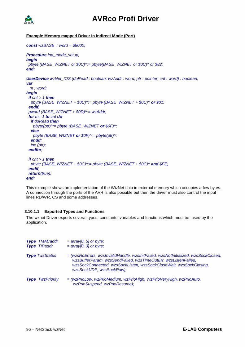
AVRco Profi Driver
96 – NetStack wzNet E-LAB Computers
Example Memory mapped Driver in Indirect Mode (Port) const wzBASE : word = $8000; Procedure ind_mode_setup; begin pbyte (BASE_WIZNET or $0C)^:= pbyte(BASE_WIZNET or $0C)^ or $82; end; UserDevice wzNet_IOS (doRead : boolean; wzAddr : word; ptr : pointer; cnt : word) : boolean; var m : word; begin if cnt > 1 then pbyte (BASE_WIZNET + $0C)^:= pbyte (BASE_WIZNET + $0C)^ or $01; endif; pword (BASE_WIZNET + $0D)^:= wzAddr; for m:=1 to cnt do if doRead then pbyte(ptr)^:= pbyte (BASE_WIZNET or $0F)^; else pbyte (BASE_WIZNET or $0F)^:= pbyte(ptr)^; endif; inc (ptr); endfor; if cnt > 1 then pbyte (BASE_WIZNET + $0C)^:= pbyte (BASE_WIZNET + $0C)^ and $FE; endif; return(true); end; This example shows an implementation of the WizNet chip in external memory which occupies a few bytes. A connection through the ports of the AVR is also possible but then the driver must also control the input lines RD/WR, CS and some addresses.
3.10.1.1 Exported Types and Functions The wznet Driver exports several types, constants, variables and functions which must be used by the application. Type TMACaddr = array[0..5] or byte; Type TIPaddr = array[0..3] or byte;
Type TwzStatus = (wzsNoErrors, wzsInvalidHandle, wzsInitFailed, wzsNotInitialized, wzsSockClosed,
wzsBufferParam, wzsSendFailed, wzsTimeOutErr, wzsListenFailed, wzsSockConnected, wzsSockListen, wzsSockCloseWait, wzsSockClosing, wzsSockUDP, wzsSockRaw);
Type TwzPriority = (wzPrioLow, wzPrioMedium, wzPrioHigh, WzPrioVeryHigh, wzPrioAuto, wzPrioSuspend, wzPrioResume);

AVRco Profi Driver
E-LAB Computers NetStack wzNet - 97
Type TwzPacketReceive = record
PeerIP : tIPaddr; PeerPort : Word; BufferPtr : Pointer; BufferLen : Word; end; Type TwzSocketSWS = (NoSillyWindow, SillyWindow); // internal use
Type TwzSocketNDAck = (NoDelayedAck, DelayedAck); // internal use Type TwzNDTimeOut = (NoDynamicTimeOut, DynamicTimeOut); // internal use Type TwzBroadcast = (NoBroadcast, Broadcast); // internal use Type TwzSocketProtocol = (CLOSED, protTCP, protUDP, protIPRAW, protMACRaw); Type TwzSocket = Record Protocol : TwzSocketProtocol; SWindow : TwzSocketSWS; // internal use DelayAck : TwzSocketNDAck; // internal use DynTimeOut : TwzNDTimeOut; // internal use Broadcast : TwzBroadcast; // internal use LocalPort : word; RemoteHost : tIPaddr; // Client mode RemotePort : Word; // Client mode IPProtocol : byte; // internal use TypeOfService : byte; // internal use MaxSegSize : word; // internal use PeerTryToDisconnect : boolean; SocketClosed : Boolean; PacketRecInfo : TwzPacketReceive; ErrorState : TwzStatus; // internal use SocketState : byte; // semaphore end; Type tSocketHandle = Pointer to twzSocket;
3.10.1.2 Exported Variables StructConst wzI2Cadd r : Byte = $7F; var TWI_DevLock : DEVICELOCK;

AVRco Profi Driver
98 – NetStack wzNet E-LAB Computers
3.10.1.3 Exported Functions and Procedures Setup Procedure wzSetIPAddr (IPAddr, Mask : tIPaddr); Procedure wzSetHWAddr (MacAddr : TMacAddr); Procedure wzSetGatewayAddr (IPAddr : tIPaddr); Procedure wzSetRetryCount (Retry : Byte); Procedure wzSetTimeOut (RetryTimeout : Word); Procedure wzReset; Function wzInit : boolean; Operation Function wzCreateSocket : tSocketHandle; Procedure wzFreeSocket (SocketPtr : tSocketHandle); Function wzInitSocket (SocketPtr : tSocketHandle) : boolean; Function wzReInitSocket (SocketPtr : tSocketHandle) : boolean; Function wzConnect (SocketPtr : tSocketHandle) : boolean; Function wzDisConnect (SocketPtr : tSocketHandle) : boolean; Function wzListen (SocketPtr : tSocketHandle) : boolean; Function wzClientConnected (SocketPtr : tSocketHandle) : Boolean; Function wzAcceptConnection (SocketPtr : tSocketHandle; YesNo : Boolean). boolean; Function wzSendBuffer (SocketPtr : tSocketHandle;Buffer : Pointer; Len : Word): Boolean; Function wzReceiveBuffer (SocketPtr : tSocketHandle): word; Function wzResumeReceive (SocketPtr : tSocketHandle) : boolean; Function wzPacketReceived (SocketPtr : tSocketHandle) : boolean; Function wzGetLastError (SocketPtr : tSocketHandle) : TwzStatus; Function wzGetSocketState (SocketPtr : tSocketHandle) : TwzStatus; Runtime Switches Procedure wzSetPriority (prio : TwzPriority); Support Functions Procedure STRtoIP (IPstr : String[15]; var Result : TIPAddress); Function IPtoSTR (IP : TIPAddress) : string[15]; Function CompareNet (a1, a2, mask : TIPAddr ) : boolean;

AVRco Profi Driver
E-LAB Computers NetStack wzNet - 99
3.10.2 Detailed Description of exported Types, Constants and Functions
Types The wzNet driver exports some type declarations which must be used by the application program: Type TMACaddr = array[0..5] or byte; This is the so called hardware address of the Ethernet/Internet unit. Formally this address can exist only once worldwide. Because most of the systems work only in subnets in most cases it is sufficient that this address is unique in this sub network. Type TIPaddr = array[0..3] or byte; This is the logical address of the network node, also called local IP address. If no server or Gateway is present, this address must be international. This means that a registration institution provides such unique addresses. With subnets the network administrator distributes these IP addresses. Type TwzStatus = (wzsNoErrors, wzsInvalidHandle, wzsInitFailed, wzsNotInitialized, wzsSockClosed,
wzsBufferParam, wzsSendFailed, wzsTimeOutErr, wzsListenFailed, wzsSockConnected, wzsSockListen, wzsSockCloseWait, wzsSockClosing, wzsSockUDP, wzsSockRaw);
All Kernel functions which can fail place a resulting error state of an operation (wzsNoErrors to wzsListenFailed) into a state byte of type TwzStatus. This state can always be read with the function wzGetLastError which returns operation results only. The current state of a socket including all, errors if any or the state of a connection, can be requested with the function wzGetSocketState. Type TwzPriority = (wzPrioLow, wzPrioMedium, wzPrioHigh, wzPrioVeryHigh, wzPrioAuto, wzPrioSuspend,
wzPrioResume); Dependent of the jobs to do and the actual condition of the system the application can control the computing time distribution in the system. The computing time of the Kernel can be set with the function wzSetPriority. So the data throughput can be controlled in a wide range. The item wzPrioVeryHigh is reserved for special high speed application and should be used with care. Type TwzPacketReceive = Record
PeerIP : tIPaddr; PeerPort : word;
BufferPtr : pointer; BufferLen : word; end; This record is internal in the Socket record (SocketHandle^. PacketRecInfo). The first two parameters contain data which allows a Server to identify the connected Client. The BufferPtr and BufferLen must be set by the application so that with Client or Server mode it is possible to receive data packets.

AVRco Profi Driver
100 – NetStack wzNet E-LAB Computers
Type TwzSocketSWS = (NoSillyWindow, SillyWindow); Only for internal usage. Type TwzSocketNDAck = (NoDelayedAck, DelayedAck); Only for internal usage. Type TwzNDTimeOut = (NoDynamicTimeOut, DynamicTimeOut); Only for internal usage. Type TwzBroadcast = (NoBroadcast, Broadcast); Only for internal usage. TType wzSocketProtocol = (CLOSED, protTCP, protUDP, protIPRAW, protMACRaw); Defines the type of connection. Only TCP and UDP is supported. Type TwzSocket = Record Protocol : TwzSocketProtocol; SWindow : TwzSocketSWS; // intern use DelayAck : TwzSocketNDAck; // intern use DynTimeOut : TwzNDTimeOut; // intern use Broadcast : TwzBroadcast; // intern use LocalPort : word; RemoteHost : tIPaddr; // Client mode RemotePort : word; // Client mode IPProtocol : byte; // intern use TypeOfService : byte; // intern use MaxSegSize : w // intern use PeerTryToDisconnect : boolean; SocketClosed : boolean; PacketRecInfo : TwzPacketReceive; ErrorState : TwzStatus; // intern use SocketState : byte; // semaphore end; Type tSocketHandle = Pointer to twzSocket; A socket contains all necessary informations which must be present to build a Client or Server connection. After creating a socket handle with wzCreateSocket the application must initialize some parameters in the socket structure by using this socket handle: SockHandle:= wzCreateSocket; // check if result = NIL !! With SockHandle^ do Protocol:= protTCP; // desired protocol, protTCP or protUDP SWindow:= SillyWindow; // normal setting DelayAck:= NoDelayedAck; // normal setting DynTimeOut:= NoDynamicTimeOut; // normal setting Broadcast:= NoBroadcast; // normal setting LocalPort:= LocPort; // current local port RemotePort:= RemPort; // Port#, only for client mode RemoteHost:= RemHost; // IP addr, only for client mode MaxSegSize:= 1460; // normal setting PacketRecInfo.BufferPtr:= @RxTxBuff; // local RxBuffer PacketRecInfo.BufferLen:= SizeOf(RxTxBuff); // local RxBuffer size endwith; The protocol defines the kind of the connection, either TCP or UDP

AVRco Profi Driver
E-LAB Computers NetStack wzNet - 101
SWindow, DelayAck, DynTimeOut, Broadcast and MaxSegSize are parameters which must be preset like shown above. Only with special cases like MACraw or IPraw there are some exceptions. Client Mode. LocalPort is only used in Client mode but it should also set in Server mode with a valid portnumber, depending of the connection type (HTTP, SMTP etc). Client Mode. RemotePort and RemoteHost are the Server IP address and the concerning port number for a Client connection to a Server. With Server and Client Mode, if packets have been received, the Kernel stores them (in a whole or in parts) into the application a buffer with each call of wzReceiveBuffer. The application must provide a separate buffer for each active socket. The application stores the address of this buffer into the parameter PacketRecInfo.BufferPtr. The concerning buffer size must be stored into the parameter PacketRecInfo.BufferLen. Server Mode. SocketState should be used by the server process to wait for a connecting client. So a continuously polling of wzClientConnected is not necessary.
procWaitFlag (SockHandle^.SocketState);
3.10.2.1 Exported Variables StructConst wzI2CAddr : Byte = $7F; This value/address is used for all Kernel accesses of the wzNet. It is the hardware address for I2C or TWI accesses. This address can be changed by the application at Start-Up, if necessary. var TWI_DevLock : DEVICELOCK; With the I2C or TWI mode the application itself also can use the I2C/TWI interface for other jobs. Because there will be dangerous bus contentions between user and Kernel accesses it must be guaranteed that only one participant at one time have access to the I2C/TWI bus.. For this purpose there is this semaphore of the type DeviceLock. Because all TWI users handle this locking internal the application must not check it before it can use the bus. The system does this check always by itself.
3.10.2.2 Exported Functions and Procedures All Kernel functions which can fail place a resulting error state of an operation into a state byte of type TwzStatus. This state can always be read with the function wzGetLastError. Setup Procedure wzSetIPAddr (IPAddr, Mask : tIPaddr); Defines the IP-address and the subnet mask of this stack. Procedure wzSetHWAddr (MacAddr : TMacAddr); Defines the MAC address of this stack. Procedure wzSetGatewayAddr (IPAddr : tIPaddr); Defines the Gateway IP-address of this stack. A Gateway is necessary if the local subnet must be left, for example to contact a DNS or SNTP server. In most cases the router in the subnet is the Gateway. With small local nets and one server the local server is the Gateway.

AVRco Profi Driver
102 – NetStack wzNet E-LAB Computers
Procedure wzSetRetryCount (Retry : byte); Defines the count of retries if a packet send failed. Should be set to 3. Procedure wzSetTimeOut (RetryTimeout : word); Defines the timeout between the retries. Should be set to 2000. Procedure wzReset; The procedure initiates a software reset in the W3100A chip. Function wzInit : boolean; The procedure initiates a software reset in the W3100A chip and then initializes the chip. Operations Function wzCreateSocket : tSocketHandle; After the initialization of the system all further operations need a handle. Without a valid handle it is impossible to call socket dependent functions. Dependent of the Define wzSocks the Kernel provides and manages up to 4 handles. Because each socket/handle requires some resources (RAM, CODE and CPU power) the Define should only import an amount of handles/sockets which is needed for a secure and fast operation. If there is only one connection opened at a time there is only the need of one socket/handle. If this function failed because all sockets/handles are occupied a NIL-pointer is returned. If successful the resulting handle (pointer) points to a structure of the type TwzSocket. This structure is fixed to this handle and must be used to exchange informations and states between the Kernel and the application. Procedure wzFreeSocket (SocketPtr : tSocketHandle); If a connection is closed and the socket/handle is not more needed the application should release the handle with this procedure. So other parts of the application can use the released socket. Function wzInitSocket (SocketPtr : tSocketHandle) : boolean; Only for UDP. Basic initialization of a socket for UDP transfers. Because of a bug in the Wiznet chip this function must be called every time if the remote IP address changes. Function wzReInitSocket (SocketPtr : tSocketHandle) : boolean; Only for UDP. Similar to wzInitSocket, but not very usefull because of this Wiznet bug. Function wzConnect (SocketPtr : tSocketHandle) : boolean; With this function a Client connects it to a server. It is mandatory for a successful connection that some global or common parameter (wzSetIPaddr etc) and connection specific parameters (SocketHandle^.xxx) are setup and initialized. Function wzDisConnect (SocketPtr : tSocketHandle) : boolean; Must be used in Server and Client mode to disconnect or abort a connection. Function wzListen (SocketPtr : tSocketHandle) : boolean; With this function a Server must be activated (set online) so that a Client can connect itself. It is mandatory for a successful connection that some global or common parameter (wzSetIPaddr etc) and connection specific parameters (SocketHandle^.xxx) are setup and initialized. Function wzClientConnected (SocketPtr : tSocketHandle) : boolean; A Server must poll this function until a true is returned. In this case a Client is connected. The peer-IP and the peer-Port of the Client can be found out with SocketHandle^. PacketRecInfo.xxx.

AVRco Profi Driver
E-LAB Computers NetStack wzNet - 103
Function wzAcceptConnection (SocketPtr : tSocketHandle; YesNo : boolean) : boolean; In Server mode, if a Client is connecting, the connection can be accepted or denied with this function. For example a connected client can be identified with SocketHandle^. PacketRecInfo.PeerIP and/or SocketHandle^. PacketRecInfo.PeerPort Function wzSendBuffer SocketPtr : tSocketHandle; Buffer : pointer; Len : word): boolean; This is the send command for the Kernel. It must be used by the Client and also by the Server. Buffer is a pointer which points to the source of the data, Len is the count of bytes to transmit. The Kernel reads count bytes out of the Buffer^ and transfers them into the internal TxBuffer of the W3100A. Function wzPacketReceived (SocketPtr : tSocketHandle) : boolean; This function returns a true if a packet has been received. Must be used in Server and also in Client mode. Function wzReceiveBuffer (SocketPtr : tSocketHandle): word; After the function above (wzPacketReceived) returned a true it is possible to fetch data. This is true with the Client and the Server mode. This function instructs the Kernel to transfer data from the W3100A internal buffer into the application area. With each call the Kernel transfers data out of the W3100A internal buffer into the target buffer until the W3100A internal buffer is empty. Because a received packet can be up to 1460 bytes in size the Kernel transfers always a byte count into the concerned buffer (SocketHandle^. PacketRecInfo. BufferPtr^) which is defined in (SocketHandle^. PacketRecInfo. BufferLen) by the application. In order to read out the whole packet out of the W3100A internal buffer this function must be called repeatedly until the whole packet is read out of the W3100A and the function returns with a 0. It is mandatory that the application must use wzReceiveBuffer until this function returns a 0. By doing this it is secure that also a big packet can be read into small buffers. This done in several partitions, of course, but it is read out completely. Function wzResumeReceive (SocketPtr : tSocketHandle) : boolean; In order to avoid overruns and similar ugly problems a Server or Client does not accept new packets after a packet is in process or is processed. The application must notify the Kernel with this function when it is ready to receive new packets. Function wzGetLastError (SocketPtr : tSocketHandle) : TwzStatus; Most of the Kernel jobs set an error state after processing a command. Functions which return a boolean commonly set also the more expressive error state which can be read by this function. The type TwzStatus includes additional conditions a socket which are non-error types and are not recognized by the function, for example wzsSockListen.

AVRco Profi Driver
104 – NetStack wzNet E-LAB Computers
Function wzGetSocketState (SocketPtr : tSocketHandle) : TwzStatus; The function above should be used if any error is raised by a Kernel action which returns a false. The above function always returns a wzsNoErrors if a normal operation is going on. If the current state of a socket must be known the function wzGetSocketState should be used because it returns also in the normal case a value which can be interpreted, for example wzsSockListen Runtime Switches Procedure wzSetPriority (prio : TwzPriority); Dependent of the jobs to do and the actual condition of the system the application can control the computing time distribution in the system. The computing time of the Kernel can be set with this function. So the data throughput can be controlled in a wide range. For example it makes less sense to run the Kernel with wzPrioHigh if there is absolutely no socket opened or active. Note Each TCP connection can not guarantee that a single packet which is send by a computer application is received as a single packet. If the receiver is too slow or the connection itself is too slow the PC joins small packets into one larger packet until either the receiver is ready to receive a new packet or the physical packet size of 1460 is reached. Example: A PC application continuously sends with high speed (packet Rate) data to a wzNet hardware. The receiver can only handle half of the packet count per second for several reasons. So the packets are stowed in the PC. The PC recognizes this and now joins two packets into one. If then the receiver accepts a new packet the PC sends this single “twin” packet. Then the game repeats. The PC joins two packets into one and transmits it etc. If the receiver expects a file (FTP) and must store it, there is no problem at all. The packet is read out and written into its destination until the packet is empty. Then the next will be processed. But if the receiver expects always a packet with a fixed size there is a problem. The receiver must always check whether there is one or multiple packets joined into one packet. Then the processing must be designed in a proper way. If the transfer rate is moderate and we can process only packets with a fixed size the joining of packets on the PC can be avoided. The wzNet must do a disconnect and a reconnect after each packet. On the PC the software must act in a similar way. Of course, it is also possible to do a handshake between the wzNet and the PC after each reception of a packet. Support functions Procedure STRtoIP (IPstr : String[15]; var Result : TIPAddress); This function converts an IP string, for example “192.168.1.16“ into an IP address. Function IPtoSTR (IP : TIPAddress) : string[15]; This is the counterpart to the function above. An IP address is changed into a string. Function CompareNet (a1, a2, mask : TIPAddr ) : boolean; This function compares two IP addresses with the help of the subnet mask. When comparing only these bits are relevant which are set to 1 in the mask. A true is returned if the compare was successful.

AVRco Profi Driver
E-LAB Computers NetStack wzNet - 105
3.10.3 Support Tools
At this time there are 2 support programs for test purposes and operation of the wzNet.
3.10.3.1 TCPconf is a program which can be called within the IDE PED32 and also operated separately. It serves for first time run of a NetStack hardware/software. The absolutely necessary setup of the board name, the IP-address and the MAC-Address can be done with this program.
3.10.3.2 TCPcheck is a complete and superior test program for testing a wzNet hardware. It can be called within the IDE PED32 and also operated separately. Example programs and schematics: example is in the directory ..\E-Lab\AVRco\Demos\TCP_Serv a small Server project example is in the directory ..\E-Lab\AVRco\Demos\TCP_ServXXL a Server project with big buffers for
speed tests example is in the directory ..\E-Lab\AVRco\Demos\TCP_Client a small Client project

AVRco Profi Driver
106 – NetStack wzNet E-LAB Computers
schematic EtherBoardII

AVRco Profi Driver
E-LAB Computers NetStack wzNet - 107
3.10.4 Telnet Server
Imports The Telnet Module must be imported into the application: Device = mega128, VCC=5; Import SysTick, TWIMaster, wzNet4; From wzNet4 import Telnet; From System import Tasks, Processes; Define ProcClock = 16000000; {Hertz} SysTick = 4; {msec} StackSize = $080, iData; FrameSize = $080, iData; Scheduler = 10,10,iData; {use the IDLE process} TaskStack = $80,iData; TaskFrame = $80; wzNet4 = I2C_TWI, iData; {hardware I2C driver, var location} TWIpresc = TWI_BR400; wzSocks = 1; {socket count, 1..4} TelnetStrLen = 80; // set work string length Uses WzKernel, wzTelnet;
3.10.4.1 Exported Types and Functions type tTelnetStr = string[TelnetStrLen]; Procedure wzTelnetSetPort (port : word); Function wzTelnetCreate : boolean; Function wzTelnetListen : boolean; Function wzTelnetConnected : boolean; Procedure wzTelnetClose; Procedure wzTelnetFree; Function wzTelnetGetState : TwzStatus; Procedure wzTelnetIdleTimeout (tnTimeout : byte); Procedure wzTelnetEcho (EchoOn : boolean); Function wzTelnetWrite (Str : tTelnetStr) : boolean; Function wzTelnetWriteLn (Str : tTelnetStr) : boolean; Function wzTelnetRead (Prompt : tTelnetStr) : tTelnetStr; Function wzTelnetGetClient (var ClientIP : tIPaddr; var ClientPort : word) : boolean; Procedure wzTelnetSetPort (port : word); This optional procedure defines the port for the Telnet server. Default port 23 is preset which can be changed with this procedure. Any change must be done before calling the Create function. Function wzTelnetCreate : boolean; This function creates the Telnet server. If all sockets are occupied or a common error occurred it returns with a false. After usage the acquired socket must be released with wzTelnetFree. A wzTelnetClose only closes the connection. The socket is still occupied.

AVRco Profi Driver
108 – NetStack wzNet E-LAB Computers
Function wzTelnetListen : boolean; After a create the server should switched into the Listen mode. Function wzTelnetConnected : boolean; If a client has connected the server doesn’t switch itself into the connected state. After starting the Listen mode the application must continuously call this function to look for a connecting client. This function also accepts a connect and switches the server into the connected state. So it is more as a simple state watch. Procedure wzTelnetIdleTimeout (tnTimeout : byte); If a client is connected this connection can be closed automatically after some time of inactivity. This is important because the server always waits for new request from the connected client. The application then is always in the f\unction wzTelnetRead which only can be left with a new client request. So a client is able to endless block the server. At least as long the client doesn’t force a disconnect or requests a disconnect by a special Telnet command. The function parameter defines the idle-timeout in seconds. The value 0 disables the timeout completely. Procedure wzTelnetClose; The application can always shut down the server at any time. A new activity must then be initialized with wzTelnetListen. This function does not free the socket. Procedure wzTelnetFree; After a wzTelnetClose the socket must be set free with this function if it is not more needed. A new client opening then must be done with wzTelnetCreate. Function wzTelnetGetState : TwzStatus; This is a pure state request without any influence to the state of the server. The type TwzStatus is already described above. Procedure wzTelnetEcho (EchoOn : boolean); A Telnet server can echo all incoming characters. This is necessary if the client has its own echo switched off. Function wzTelnetWrite (Str : tTelnetStr) : boolean; The transmit instruction for the server. The string then is send to the client. Function wzTelnetWriteLn (Str : tTelnetStr) : boolean; The same as above but a CRLF is appended. Function wzTelnetRead (Prompt : tTelnetStr) : tTelnetStr; This is the main function of a Telnet server if a client is connected. The prompt string is send to the client. Then function waits until the client has replied an answer. Because it is possible that this does never happen a blocked server is the result. Also the application can be blocked. Because of this the Telnet timeout value should always set > 0. Function wzTelnetGetClient (var ClientIP : tIPaddr; var ClientPort : word) : boolean; If a client is connected its IP-address and port can be read at any time. Example program: an example is in the directory ..\E-Lab\AVRco\Demos\TCP_Telnet

AVRco Profi Driver
E-LAB Computers NetStack wzNet - 109
3.10.5 DNS Client
A DNS server translates a literal Internet address into a IP address. Therefore a DNS client must be used which solves this job. Imports Device = mega128, VCC=5; Import SysTick, TWIMaster, wzNet4; From wzNet4 import DNS; From System Import Tasks, Processes; Define ProcClock = 16000000; {Hertz} SysTick = 4; {msec} StackSize = $080, iData; FrameSize = $080, iData; Scheduler = 10,10,iData; {use the IDLE process} TaskStack = $80,iData; TaskFrame = $80; wzNet4 = I2C_TWI, iData; {hardware I2C driver, var location} TWIpresc = TWI_BR400; wzSocks = 1; {socket count, 1..4} Uses WzKernel, wzDNS;
3.10.5.1 Exported Functions Procedure wzSetDNSserver (IPAddr : tIPaddr); With this function the IP-address of a remote DNS server must be set once. It is valid until a system restart. Function wzDNSQueryHost (Buffer : Pointer; BuffLen : word; Hostname : pointer to string; var Result_IP : tIPaddr) : boolean; This function creates the DNS client. The client connects to the supplied DNS server, passes the Internet address and gets the resulting IP-address, if exist. The client then is completely removed. Buffer is a pointer which points to a memory (RAM) area of at least 300 bytes of size. BuffLen defines the size of this buffer. HostName must point to a string in RAM which must contain the literal Internet address. Result_IP if successful the resulting IP address is stored here. Example program: an example is in the directory ..\E-Lab\AVRco\Demos\TCP_DNS

AVRco Profi Driver
110 – NetStack wzNet E-LAB Computers
3.10.6 SNTP client
A SNTP server returns the actual time (GMT) and date. Therefore a SNTP client must be used which solves this job. Imports Device = mega128, VCC=5; Import SysTick, TWIMaster, wzNet4; From wzNet4 import SNTP; From System import Tasks, Processes; Define … … Uses WzKernel, wzSNTP;
3.10.6.1 Exported Types and Functions structconst // value for Germany! Other time zones must overwrite this value TimeZoneBias : integer = 2; // hours TimeZoneBiasM : byte = 0; // minutes, optional minutes offset type tDayOfWeek = (dwSunday, dwMonday, dwTuesday, dwWednesday, dwThursday, dwFriday,
dwSaturday); tDateTime = record dayofWeek : tDayOfWeek; year : word; month : byte; day : byte; hour : byte; minute : byte; second : byte; end; Procedure wzSetSNTPserver (IPAddr : tIPaddr); With this function the IP-address of a remote SNTP server must be set once. It is valid until a system restart. Function wzSNTPQueryDateTime (Buffer : pointer; BuffLen : word; var DateTime : tDateTime) : boolean; This function creates the SNTP client. The client connects to the supplied SNTP server and receives the actual time (GMT) and date. The client then is completely removed.
AVRco Profi Driver
E-LAB Computers NetStack wzNet - 111
Buffer is a pointer which points to a memory (RAM) area of at least 60 bytes of size. BuffLen defines the size of this buffer. DateTime is a variable which must be supplied by the application. After a successful operation it contains the actual time and date. The value of the constant TimeZoneBias is already included into the calculation. TimeZoneBiasM is an optional constant (initial value = 0) which can/must be used in some regions. Example program: an example is in the directory ..\E-Lab\AVRco\Demos\TCP_SNTP

AVRco Profi Driver
112 – ModBus ASCII Slave E-LAB Computers
3.11 ModBus ASCII Serial Slave implemented with great support from Zeljko Avramovic ("AVRA")
Attention: ModBus communication is a very complex thing. It can here only be touched. For a deep understanding you must study the corresponding literature. See also the links in the foot-notes!
3.11.1 Introduction
In a modern industrial world, our small box is not lonely and it needs to talk to different devices. It is often just a small block in a big lego set, but usually an important one. It is wise to be compatible to some industrial communication protocol, and MODBUS 1 is a logical choice. It is open, wide spread, expandable and well documented. There are more than 7 million modbus devices already installed (mostly PLCs 2 and dummy “only read sensor“ devices). It is a single master multi slaves request/reply protocol, and it is not tied to any physical layer. Most commonly used are RS232/485 (ASCII and RTU variants) and Ethernet (TCP/IP) implementations. Since RTU needs an interrupt to catch and we wanted to save resources, we implemented an MODBUS ASCII slave as a background process and digital and analog ins and outs share the same address space (they are mapped to each other, as specification allows this). Good thing with ASCII is that you only need terminal software for testing 3. All important modbus functions are here: 01 – Read Coils, 02 – Read Discrete Inputs, 03 – Read Holding Registers, 04 – Read Input Registers, 05 – Write Single Coil, 06 – Write Single Register, 15 – Write Multiple Coils, 16 – Write Multiple Registers. As you see, modbus protocol knows only how to transfer bits (digital ins and outs) and words (analog ins and outs). In PLC terminology bits are called coils and words are called registers. It’s up to you to pack other types like integers, floats or strings in a server, and then unpack them in a client. Specification says that you address digital and analog ins and outs, but usually you don’t. It is more common that you have intelligent modbus slave device that gives you access to some address space with tags 4, and it’s programmable logic maps them to real ins and outs after each scan 5.
1 MODBUS - Open industrial communication protocol (www.modbus.org). 2 PLC - Programmable Logic Controller , a device which can read digital and analog inputs and according to these do some actions, like control digital and analog outputs. Take a look at www.plcs.net. 3 Communication testing tools: at www.ozm.cz/ivobauer/modlink, bray.velenje.cx/avr/terminal, www.wittecom.com, www.focus-sw.com/modpoll.html, www.jotmobile.com/plcpilot.html. 4 TAG - Smallest type of data in a device that can be read or written. 5 SCAN - Software in PLCs runs in an infinite loop. Each cycle is called a scan.

AVRco Profi Driver
E-LAB Computers ModBus ASCII Slave - 113
Back in a stone age, it was quite a mess. There were hundreds of different communication protocols, and power of HMI/SCADA 6 software was measured by the number of protocols it supported. Every SCADA vendor had to reinvent the wheel over and over again, and a lot of energy was wasted on same problems by different teams. There were efforts to make driver once and use it with different applications, but they were limited and more a quick fix then a solution. OLE 7 and DDE 8 are a fine example of this. That could not last too long and big players wanted a breakthrough. So, OPC 9 was born. We finally got a universal way to communicate with PLCs and other devices. Once we have an OPC server for a device, everyone can read and write tags in it. Alarms, trending and historic data access is just a module away. The beauty is that you are not tied to a single vendor. Now back to our story, if we have an OPC server for serial ASCII MODBUS (and there are planty to choose from), our small box is in OPC business, too! Visualisation and instrumentation becomes really a plug and play. Now you have enough to make a PLC on your own. Instead of making another "lonely" device, you have connectivity with the rest of the world. You can talk with other professional devices, with PCs for control, monitoring, visualisation and data acquisition, in next room or other side of the globe. All tools 10 are at your disposal and you have instant MODBUS, OPC, SCADA, Delphi, Visual Basic, C++, C#, Java and Internet Explorer compatibility. For more info take a look at master examples and related document. I was very excited when my little box was talking for the first time with the same professional SCADA software that is used in nuclear plants, beer or oil factories, and other modern automated plants. Good luck! Master Examples: ModBus-ASCII-Masters.zip is to be found at http://www.e-lab.de/avrco/index_en.html
6 HMI/SCADA – Human Machine Interface / Supervisory Control and Data Acquisition. Software for visualisation, monitoring, data acquisition and control of industrial processes. End users are usually operators and technologists in a production line. Take a look at www.citect.com, www.siemens.com/wincc, www.iconics.com, www.smartscada.com. 7 OLE - Object Linking and Embedding (Microsoft). 8 DDE - Dynamic Data Exchange (Microsoft). 9 OPC - OLE for Process Control. Industry standard created with the collaboration of a number a leading worldwide automation and hardware software suppliers working in cooperation with Microsoft. The organization that manages this standard is the OPC Foundation (www.opcfoundation.org). Based on Microsoft's OLE (now ActiveX), COM and DCOM technologies, OPC consists of a standard set of interfaces, properties, and methods for use in process control and manufacturing automation applications. The ActiveX/COM technologies define how individual software components interact and share data. OPC provides a common interface for communicating with diverse process control devices, regardless of the controlling software or devices in the process. Although there are many OPC specifications the most commonly used are OPC DA (Data Access), OPC AE (Alarm and Events), and OPC HDA (Historical Data Access). 10 Client side programming: www.opcconnect.com, www.ozm.cz/ivobauer/modlink, www.pockethmi.com, www.signonline.de/dopc, www.abakus.vcl, www.iocomp.com, www.automatedsolutions.com, mbserver.w3.to www.smartscada.com, msol.io.com/ikysil/index-en.html, www.g7jjf.demon.co.uk/ppc.htm, www.prel.co.uk.

AVRco Profi Driver
114 – ModBus ASCII Slave E-LAB Computers
3.11.2 Implementation
Imports As usual with AVRco the driver must be imported. Import SysTick, SerPort, ModBus; //SerPort & SerPort2 are supported { $DEFINE MOD_RADIO} //important when RF is used From System Import Processes; //driver is implemented in process From ModBus Import {MOD_Radio}; //if MODBUS is used on RF line Define //example for MEGA128 ProcClock = 16000000; //Hertz SysTick = 10; //msec StackSize = $0020, iData; FrameSize = $0050, iData; Scheduler = iData; SerPort = 19200, Databit7, parEven, Stop1; //ASCII default SerPortDTR = PinB, 7, Positive; //RF usually has busy signal SerCtrl = PortD, 2, Positive; //control line if RS485 used RxBuffer = 255, iData; //recommended, but may be lower TxBuffer = 100, iData; //recommended, but may be lower ModBus = SerPort, 40; //use port 1/2, capacity in words ModBusMode = ASCII; //what modbus mode to use Uses ModBusServASCII; //modbus logic is in this unit var {$IDATA} {$MODBUS filename} //build filename.pmbl to use with MODBUS Tester tool ModBuff[@ModDPR] : record //common memory for all modbus tags tag1 : mb_tag_type; tag2 : mb_tag_type; ... tagN : mb_tag_type; end; //do not exceed defined capacity in words! // these are predefined tag types that you can use (mb_tag_type): // // mb_InpB = byte; { !! always as couples } // mb_RdWrB = byte; { !! always as couples } // mb_InpW = word; // mb_RdWrW = word; {prefix mb_Inp is used to identify} // mb_InpI = Integer; {that tag is read only, usually used} // mb_RdWrI = Integer; {for mapping input from some sensor,} // mb_InpW32 = longword; {and prefix mb_RdWr is for read/write,} // mb_RdWrW32 = longword; {usually used for physical outputs.} // mb_InpI32 = longInt; // mb_RdWrI32 = longInt; {sufixes B, W, I, W32, I32 and F are} // mb_InpF = Float; {used to identify byte, word, int,} // mb_RdWrF = Float; {longword, longint, and float types} // // additional types are one-dimensional arrays of byte and bitsets. // Bitsets are treated as writable Coils or readable DiscreteInputs, // depending on the name prefix "rw_" (all with this prefix are writable) // Booleans are indirectly supported in bitsets, bytes, coils or discrete inputs.

AVRco Profi Driver
E-LAB Computers ModBus ASCII Slave - 115
Later on, you can change tag values anywhere in code (usually in main loop or some process) like this
ModBuff.tagN:= NewValue; That’s all. Now, when modbus master asks for this value it will be automatically sent to him! Every modbus device must have a unique id. The default is 1, but you can get/set it easily (in a modbus network with many devices you will probably initially read some DIP switches) if you take a look at these declarations: Procedure mb_SetModBusDevID (id: byte); {set device ID} Function mb_GetModBusDevID: byte; {get device ID} All ASCII modbus messages end with <CR><LF> so your modbus slave (or server if you prefer) knows when message ends, but by default it will not wait forever for a ’0’..’9’ or ’A’..’F’ character in a receiving message. It will wait for a maximum of 1000 miliseconds before it drops the whole message (as stated in specification). Luckily for us, this behaviour can be changed so we don’t have to be speed champions in terminal typing. We can set it to any number of miliseconds, and if we set it to zero it will wait for ever. Everything is apparent from these declarations: Procedure mb_SetModBusTimeout (time: word); {set timeout in ms} Function mb_GetModBusTimeout: word; {get timeout in ms} If you take a look at following declarations, it will be clear that you can easily implement Delphi like events before or after each client read/write of server’s modbus memory. type
tBeforeRegisterRead = Procedure (RegisterNumber: word); tAfterRegisterRead = Procedure (RegisterNumber: word); tBeforeRegisterWrite = Procedure (RegisterNumber: word; var NewValue: word); tAfterRegisterWrite = Procedure (RegisterNumber: word); tBeforeCoilRead = Procedure (CoilNumber: word); tAfterCoilRead = Procedure (CoilNumber: word); tBeforeCoilWrite = Procedure (CoilNumber: word; var NewValue: boolean); tAfterCoilWrite = Procedure (CoilNumber: word);
Procedures
Procedure mb_setBeforeRegisterRead (proc: tBeforeRegisterRead); Procedure mb_setAfterRegisterRead (proc: tAfterRegisterRead); Procedure mb_setBeforeRegisterWrite (proc: tBeforeRegisterWrite); Procedure mb_setAfterRegisterWrite (proc: tAfterRegisterWrite); Procedure mb_setBeforeCoilRead (proc: tBeforeCoilRead); Procedure mb_setAfterCoilRead (proc: tAfterCoilRead); Procedure mb_setBeforeCoilWrite (proc: tBeforeCoilWrite); Procedure mb_setAfterCoilWrite (proc: tAfterCoilWrite);
Attention: These functions above are all Callbacks which are called out of interrupts. With Callbacks it is essential: in a callback no calls of drivers or driver functions. No time consuming operations, especially no delays or waits for other events. Further interrupts are disabled in this time and for example UARTs will loose chars by an overrun.

AVRco Profi Driver
116 – ModBus ASCII Slave E-LAB Computers
Now, if we write something like this in our program Procedure mb_BeforeRegisterRead (RegisterNumber: word); begin // here you can process register before sending it to a client, // or just increment some counter end; and in initialization you set pointer to this new event with a call like this mb_SetBeforeRegisterRead (@mb_BeforeRegisterRead); // enable event
then we will have our procedure called before tag is actually being read on client’s request. Just keep in mind that your callback functions need to be very fast, almost like we have in interrupts. You should just fire some flag, use a pipe, or do a quick memory move in a callback procedure. You should avoid callbacks using WriteLn or some other slow code since you risk that another MODBUS message arives before current callback is finished, and that can be fatal for your application
Example program: an example can be found in the directory ..\E-Lab\AVRco\Demos\ModBus_ASCII

AVRco Profi Driver
E-LAB Computers ModBus RTU Slave - 117
3.12 ModBus RTU Serial Slave implemented with great support from Zeljko Avramovic ("AVRA")
Attention: ModBus communication is a very complex thing. It can here only be touched. For a deep understanding you must study the corresponding literature. See also the links in the foot-notes and the foot-notes in the chapter MODBUS ASCII SERIAL SLAVE! To avoid repitition, the MODBUS introduction is skipped, so it is highly recommended that you first read “MODBUS ASCII SERIAL SLAVE IMPLEMENTATION“ and official MODBUS documents 11. In short, this driver gives data blocks to your AVR serial slave, with words and booleans to read and write (other types can be packed into these words, too), and a transparent communication is initiated by master. The only thing you have to do is to read or write to these data blocks, and changes are seen automatically by both master and slave. In MODBUS terminology you can also say that slaves are actually servers (listening for a message from master), and master is actually a client (there can be only one master on MODBUS network). We wanted to save memory, and the specification recommends doing it by overlaping read data blocks (as far as MODBUS is concerned these are all digital and analog physical inputs, although we can also put here internal variables) and write data blocks (the same story for digital and analog physical outputs) into each other, so they overlap. Even digital and analog signals overlap each other. For example digital input 20 is the same bit as for digital output 20, and they overlap with second analog input (which is the same word used for second analog output). This can be handy sometimes, but generally you should avoid placing digital signals in the same words as used for analog signals. Because read and write data blocks also overlap, you should also make sure that both master and slave do not write to same memory space in the data block. The best way to avoid this is to start read only tags counting from zero, and for read/write tags use an offset which is higher than any read only tag. The quickest way to test MODBUS communication is to use E-LAB’s Modbus Tester (you can find it under the Tools menu in PED32 IDE). Unlike ASCII, RTU is resources hungry. It’s precise timing needs one timer and RXRDY interrupt, but the benefit is that in the same time frame you can transfer twice as much data.
11 www.modbus-ida.org: Modbus_over_serial_line_V1.pdf, ModbusApplicationProtocol_v1_1.pdf

AVRco Profi Driver
118 – ModBus RTU Slave E-LAB Computers
Since more horse power is needed anyway, compared to the ASCII version more MODBUS functions were implemented. So, as well as ASCII implemented functions 01 – Read Coils, 02 – Read Discrete Inputs, 03 – Read Holding Registers, 04 – Read Input Registers, 05 – Write Single Coil, 06 – Write Single Register, 15 – Write Multiple Coils, 16 – Write Multiple Registers. you also have functions 07 – Read Exception Status
(8 bits which can be nicely used to represent status of your device in a standard way), and
08 – Diagnostics (with all 15 diagnostic subfunctions – for more info read official MODBUS documents).
Testing diagnostic subfunctions is easy with the ModLink demo 12. Of course, OPC servers 13 are also available for serial RTU MODBUS slaves, so your little device can be in the big OPC business, too. If you use RS485, then you should also know that it is recommended to use 2W-cabling (4W-cabling is an option) and RJ45 connectors (DB9 is an option). For additional information you should take a look at Modbus_over_serial_line_V1.pdf.
12 www.ozm.cz/ivobauer/modlink 13 OPC - OLE for Process Control. Industry standard created with the collaboration of a number a leading worldwide automation and hardware software suppliers working in cooperation with Microsoft. The organization that manages this standard is the OPC Foundation (www.opcfoundation.org). Based on Microsoft's OLE (now ActiveX), COM and DCOM technologies, OPC consists of a standard set of interfaces, properties, and methods for use in process control and manufacturing automation applications. The ActiveX/COM technologies define how individual software components interact and share data. OPC provides a common interface for communicating with diverse process control devices, regardless of the controlling software or devices in the process. Although there are many OPC specifications the most commonly used is OPC DA (Data Access), but OPC AE (Alarm and Events) and OPC HDA (Historical Data Access) are also widely used.

AVRco Profi Driver
E-LAB Computers ModBus RTU Slave - 119
3.12.1 Implementation
Imports As usual with AVRco the driver must be imported. Import SerPort, ModBus; //SerPort & SerPort2 are supported { $DEFINE MOD_RADIO} //important only when RF is used From System Import Processes; //driver needs processes From ModBus import {MOD_Radio}; //if MODBUS is used on RF line Define //example for MEGA128 ProcClock = 16000000; StackSize = $0020, iData; FrameSize = $0050, iData; Scheduler = iData; SerPort = 19200, Databit8, parEven, Stop1; //RTU default SerPortDTR = PinB, 7, Positive; //if RF has busy output signal SerCtrl = PortG, 3, Positive; //control line if RS485 used RxBuffer = 255, iData; //recommended, but may be lower TxBuffer = 100, iData; //recommended, but may be lower ModBus = SerPort, 37, iData, 240; //port, capacity of MODBUS data block in words, //iData/xData, effective bytes (Framesize = effective bytes + //function code + crc + EXTRA) ModBusMode = RTU, Timer3; //MODBUS mode, timer 1..3
Uses ModBusServRTU; //MODBUS logic is in this unit var {$IDATA} {$MODBUS filename} //build filename.pmbl to use with MODBUS Tester tool ModBuff[@ModDPR] :
record //common memory for all modbus tags tag1 : mb_tag_type; tag2 : mb_tag_type; ... tagN : mb_tag_type; end; //do not exceed defined capacity in words! // these are predefined tag types that you can use (mb_tag_type): // // mb_InpB = byte; { !! always as couples } // mb_RdWrB = byte; { !! always as couples } // mb_InpW = word; // mb_RdWrW = word; {prefix mb_Inp is used to identify} // mb_InpI = Integer; {that tag is read only, usually used} // mb_RdWrI = Integer; {for mapping input from some sensor,} // mb_InpW32 = longword; {and prefix mb_RdWr is for read/write,} // mb_RdWrW32 = longword; {usually used for physical outputs.} // mb_InpI32 = longInt; // mb_RdWrI32 = longInt; {sufixes B, W, I, W32, I32 and F are} // mb_InpF = Float; {used to identify byte, word, int,} // mb_RdWrF = Float; {longword, longint, and float types}

AVRco Profi Driver
120 – ModBus RTU Slave E-LAB Computers
// // additional types are one-dimensional arrays of byte and bitsets. // Bitsets are treated as writable Coils or readable DiscreteInputs, // depending on the name prefix "rw_" (all with this prefix are writable) // Booleans are indirectly supported in bitsets, bytes, coils or discrete // inputs.
Later on, you can change tag values anywhere in code (usually in main loop or some process) like this ModBuff.tagN:= NewValue; That’s all. Now, when MODBUS master asks for this value it will be automatically sent to him! Every MODBUS device must have a unique id. Default is 1, but you can get/set it easily (in a MODBUS network with many devices you will probably initially read some DIP switches) if you take a look at these declarations: Procedure mb_SetModBusDevID (id: byte); {set device ID} Function mb_GetModBusDevID: byte; {get device ID} In RTU version MODBUS function 7 is implemented (Read Exception Status). It can be very handy to represent status of your device in official way. Specification does not define individual bits (so called exception status outputs) in exception status byte, so they are all yours to set them freely on your will. You can get/set exception status of your device easily if you take a look at these declarations: Procedure mb_SetModBusExceptionStatus (status: byte); {set status} Function mb_GetModBusExceptionStatus: byte; {get status} If you take a look at following declarations, it will be clear that you can easily implement Delphi like events before or after each client read/write of server’s modbus memory. type
tBeforeRegisterRead = Procedure (RegisterNumber: word); tAfterRegisterRead = Procedure (RegisterNumber: word); tBeforeRegisterWrite = Procedure (RegisterNumber: word; var NewValue: word); tAfterRegisterWrite = Procedure (RegisterNumber: word); tBeforeCoilRead = Procedure (CoilNumber: word); tAfterCoilRead = Procedure (CoilNumber: word); tBeforeCoilWrite = Procedure (CoilNumber: word; var NewValue: boolean); tAfterCoilWrite = Procedure (CoilNumber: word);
Procedures
Procedure mb_setBeforeRegisterRead (proc: tBeforeRegisterRead); Procedure mb_setAfterRegisterRead (proc: tAfterRegisterRead); Procedure mb_setBeforeRegisterWrite (proc: tBeforeRegisterWrite); Procedure mb_setAfterRegisterWrite (proc: tAfterRegisterWrite); Procedure mb_setBeforeCoilRead (proc: tBeforeCoilRead); Procedure mb_setAfterCoilRead (proc: tAfterCoilRead); Procedure mb_setBeforeCoilWrite (proc: tBeforeCoilWrite); Procedure mb_setAfterCoilWrite (proc: tAfterCoilWrite);

AVRco Profi Driver
E-LAB Computers ModBus RTU Slave - 121
Now, if we write something like this in our program Procedure mb_BeforeRegisterRead (RegisterNumber: word); begin // here you can process register before sending it to a client, // or just increment some counter end; and in initialization you set pointer to this new event with a call like this mb_SetBeforeRegisterRead (@mb_BeforeRegisterRead); // enable event then we will have our procedure called before tag is actually being read on client’s request. Anyway, it is best to take a deep look at provided MODBUS RTU serial slave example. Example program: an example can be found in the directory ..\E-Lab\AVRco\Demos\ModBus_RTU

AVRco Profi Driver
122 – NetStack TINA E-LAB Computers
3.13 TINA EtherNet/InterNet Driver AVRco NetStack implemented with great support from Udo Purwin
There are many ways how two or more units (processors, control units etc) can communicate with each other. One of them is Ethernet. The term “embedded Ethernet“ is heavily in use in the last time in the context with fast connections between control units or the connection between PC and control units. Ethernet defines the physical connection between two devices. The definition includes the type of cables and wiring, the access and collision mechanisms, and also the low-level telegram format (MAC-addresses). So Ethernet can be seen on one level with CAN-Bus for example. Because Ethernet (and IP) was introduced before the OSI-stack was defined it is based on the (4-layer) model of the DoD (Department of Defence). Within the OSI-model Ethernet is not really unambiguous because it is relevant for the "DataLink-Layer" (MAC-addresses, CRC etc.) and also in the "Physical Layer" (UTP, RG58, CSMA/CD, etc.). Today "Ethernet" is often a synonym for the whole IP-protocol family. "FTP", "SNMP", "TCP", "UDP", "ICMP", "ARP","BOOTP" ... - all are mainly meant with "Ethernet". Any application (an own one or FTP or PING) communicates only with the OSI "Transport Layer", like TCP/IP or UDP/IP (which is the DoD Layer: "Host-to-Host"). The underlying low-level and physical layers must be provided by the driver implementation. In order to support different transport layers with one software driver there must be a hardware independent interface. This was started with the driver
TransportationIndependendNetworkAccess TINA The intention of this driver is to provide all UDP protocols to the application, independent of the line drivers (MAC etc). In addition there will be several drivers on the hardware side like ENC28J60, ENC424J600, an UART (SLIP) and an User Device driver (generic). There are only these protocols implemented: UDP, xUDP and ICMP-PING. On the hardware side only the MicroChip ENC28J60 and ENC424J600 are implemented. Future implementations will also support the SLIP protocol.
3.13.1 Architecture
The basic implementation of this protocol stack is a MultiTasking Kernel which does all the jobs on protocol level. This Kernel (Unit Tina) runs completely in the background and is mainly build of a special Task (TINA_Job). The advantage of this construction is the absolute transparency of the Kernel which makes the application independent from the Kernel. The application for example does not “hang“ if the STACK runs into a timeout which can last up to 10sec. A total blocking of the system as is usual with simple implementations is absolutely impossible here. Up to 8 sockets (connections) can be opened at the same time. They are working independent from each other and each socket can have its own protocol, in server and also in the client mode. Because of the construction of the Kernel as a separate special Task (TINA_Job) eight active sockets have not much influence onto the computing power and throughput of the system. As a drawback the maximum throughput of a socket is limited to about 100kByte/sec (ENCxxxx), depended of the interface speed of the hardware. But this again is mostly independent of the count of active sockets.

AVRco Profi Driver
E-LAB Computers NetStack TINA - 123
The intentions of such a system are always two essential points, speed and reliability. With a real application and its basics (CPU, memory etc) there is always a compromise between these items. Simply by the limited computing power of the AVR the throughput is also very limited, compared with a PC. One must decide which is more important, high speed and as a consequence a restricted computing time for all other jobs of the application, or a moderate throughput but much more power for the rest of the system. We choose the latter one. If the Ethernet is used as it was intended for, as an additional communication channel like an UART or I2C, then it must be clear that a high speed implementation ends in itself. In other words, a MP3 player uses the AVR by 100% and there is nearly no time for the rest or the main jobs. The used time slice technique with its flexible coupling between application and the Ethernet process (TINA_Job) slows down the throughput but has the advantage that the existing computing power can optimal be shared between all jobs. A blocking can not happen in contrary to a tight coupled system where the application is directly connected to the Ethernet driver. An additional point which limits the throughput in our implementation is the usage of the SPI as an interface to the hardware. Here the 8MBit/sec with SPI/ENC is a hard limit. Higher SPI speed maybe possible. But this doesn’t speed-up much more because then the time slice becomes the limitation. Nevertheless it is possible to control the throughput in a wide range by a proper setting of the priority of the TINA JobHandler. This is achievable: CPU 16MHz JobHandler Priority high Min 16kB Flash min 2kB RAM ENCxxxx with SPI packetsize 20Byte ca. 500 Packets/sec -> 9kByte/sec xUDP packetsize 1kByte ca. 110 Packets/sec -> 110kByte/sec xUDP W3100A with TWI packetsize 1.4kByte ca. 20 packets/sec -> 28kByte/sec TCP/IP
3.13.1.1 Imports As usual with AVRco the driver must be imported: Import SysTick, TINAstack, ...; Because the TINA-ENC driver uses one of the SPI ports of the CPU this SPI is explicitly connected to the ENC chip and can only be used by other parts of the system with some additional support. With big Megas the MSPIx ports can be used. With XMegas the 4 possible SPIs can be used: SPI_C, SPI_D etc. The Kernel does not need the import of the MultiTasking system, but it makes sense that each socket is controlled by a separate process. Basically the TINA Kernel uses a hardware timer because it works absolutely independent of the SysTick. Timer1, Timer2 or Timer3 can be used, if present. With XMegas one of the possible 8 timers must be used: Timer_C0, Timer_C1 etc. Note: The current ENC chips need a SPI data rate of at least 8Mbit/sec. To achieve this, the CPU must run at least with 16MHz. These imports now expect some defines.

AVRco Profi Driver
124 – NetStack TINA E-LAB Computers
3.13.1.2 Defines Define ProcClock = 16000000; // Hertz StackSize = $0080, iData; // min size FrameSize = $00C0, iData; // min size xData = $8000, $87ff; // 2kB optional, only necessary with the xData define below TINAdriver = ENC28J60[, xData]; // TINA hardware, optional buffers in xData // TINAdriver = ENC424J600; // TINA hardware, alternative chip, WizNet, WizNet5200 TINAport = SPI, PortB, 0; // SPItyp, SS_Port, SS_Pin // TINAport = MSPI0, PortA, 4; // SPItyp, SS_Port, SS_Pin // TINAport = SPI_Soft, PortD.7, PortD.6, PortD.5, PortD.4; // SPItyp, SS, SCLK, MOSI, MISO TINAtimer = Timer3; // 1..3 TINAsockets = 4; // socket count, 1..8 XMega With the XMegas upto four SPI-ports are supported:
SPI_C, SPI_D, SPI_E or SPI_F Because of this the desired SPI port must be defined: TINAport = SPI_C, PortF, Pin3; The XMegas provide upto 8 timers:
Timer_C0, Timer_C1, Timer_D0, Timer_D1 etc. One of them must be used: TINAtimer = Timer_F1;
3.13.1.3 Exported Types and Functions The TINA Driver exports several types, constants, variables and functions which must be used by the application. Type TMACaddr = array[0..5] of byte; Type TIPaddr = array[0..3] of byte; Type TTINAStatus = (TinasNoErrors, TinasInvalidHandle, TinasInitFailed, TinasNotInitialized,
TinasSockClosed, TinasBufferParam, TinasSendFailed, TinasTimeOutErr, TinasListenFailed, TinasSockConnected, TinasSockListen, TinasSockCloseWait, TinasSockClosing, TinasSockUDP, TinasSockRaw);
Type TtinaPriority = (TinaPrioMedium, TinaPrioLow, TinaPrioHigh, TinaPrioVeryHigh,
TinaPrioVeryLow, TinaPrioAuto, TinaPrioSuspend, TinaPrioResume); Type TtinaPacketReceive = Record PeerIP : tIPaddr; PeerPort : Word; RecLen : Word; BufferPtr : Pointer; BufferLen : Word; end; Type TTinaSocketSWS = (NoSillyWindow, SillyWindow); TTinaSocketNDAck = (NoDelayedAck, DelayedAck); TTinaNDTimeOut = (NoDynamicTimeOut, DynamicTimeOut); TTinaBroadcast = (NoBroadcast, Broadcast); TTinaxUDPAKNPort = (xAKNLocalPort, xAKNRemotePort, xAKNRemoteDynamicPort); Type TProtocolType = (pICMP, pUDP, pTCP, pxUDP);

AVRco Profi Driver
E-LAB Computers NetStack TINA - 125
Type TTinaSocket = Record Protocol : TProtocolType; Swindow : TTinaSocketSWS; DelayAck : TTinaSocketNDAck; DynTimeOut : TTinaNDTimeOut; Broadcast : TTinaBroadcast; LocalPort : Word; RemoteHost : tIPaddr; RemotePort : Word; TimeOut : LongWord; RetryCount : Byte; AKNPort : TTinaxUDPAKNPort; PeerTryToDisconnect : Boolean; SocketClosed : Boolean; PacketRecInfo : TTinaPacketReceive; ErrorState : TTINAStatus; SocketState : Byte; end; tSocketHandle = Pointer to TTinaSocket; TTinaCore = Record IP : tIPaddr; Mask : tIPaddr; Gateway : tIPaddr; Mac : TMacAddr; TimeOut : LongWord; Retry : Byte; Prio : TTinaPriority; ResponsePing : Boolean; RXCheckSumCheck : Boolean; SendICMPCtrlMessages : Boolean; end;
3.13.1.4 Exported Variables var TinaCore : TTinaCore;
3.13.1.5 Exported Functions and Procedures Setup Function TINA_Init : Boolean; Procedure TINA_Start; Procedure TINA_Stop; Function TinaLinkStat : boolean; Operation Function GetDefaultMAC: tMACaddr; // ENC424J600 only Function TinaInitSocket (SocketPtr : tSocketHandle) : Boolean; Function TinaCreateSocket : tSocketHandle; Function TinaRxStat(SocketPtr : tSocketHandle) : Boolean; Function TinaPacketReceived (SocketPtr : tSocketHandle) : Boolean; Function TinaResumeReceive (SocketPtr : tSocketHandle) : Boolean; Function TinaSendPacket (SocketPtr : tSocketHandle; Buffer : Pointer; Len : Word) : Boolean; Procedure TinaFreeSocket (SocketPtr : tSocketHandle);

AVRco Profi Driver
126 – NetStack TINA E-LAB Computers
Runtime Switches Procedure TINASetPriority (prio : TTinaPriority); Support Functions Function TINA_Ping (PingAdr : TIPAddr; TimeOut : Word) : Word; Procedure STRtoIP (IPstr : String[15]; var Result : TIPAddress); Function IPtoSTR (IP : TIPAddress) : String[15]; Function CompareNet (a1, a2, mask : TIPAddr ) : boolean;
3.13.2 Detailed Description of exported Types, Constants and Functions
Types The TINA driver exports some type declarations which must be used by the application program: Type TMACaddr = array[0..5] or byte; This is the so called hardware address of the Ethernet/Internet unit. Formally this address can exist only once worldwide. Because most of the systems work only in subnets in most cases it is sufficient that this address is unique in this sub network. Type TIPaddr = array[0..3] or byte; This is the logical address of the network node, also called local IP address. If no server or Gateway is present, this address must be international. This means that a registration institution provides such unique addresses. With subnets the network administrator distributes these IP addresses. Function GetDefaultMAC: tMACaddr; // ENC424J600 only This function is only available with the ENC424J600. This chip has a build-in unique MAC address. This address can be changed by the application. Because the TINA should not be changed basically (TINAcore, TINA_Init), this address must be read out from the ENC at startup with GetDefaultMAC and then placed into the record TINAcore which is then be used by TINA_Init.
3.13.3 The xUDP Protocol
The currently implemented UDP protocol is a so called unsecured protocol. This means that a packet can be transferred but the recipient never sends an acknowledge or similar. So the sender never knows whether the packet is transferred successfully or not and whether the data was valid or not. With many applications this is don’t care. Think of speech/voice transfers. If here a packet fails so a part of a word is missing which leads to a small distortion which often is not recognized by a human. But for some applications this is not tolerable and one has to switch to the much slower and more complex TCP/IP protocol. On the other hand if we implement a handshake operation within UDP including timeouts and retries, so it is possible to have a very secure, reliable and much faster data transfer. The xUDP protocol in the TINA Kernel waits after a packet transfer an amount of time until the recipient has send back a $A55A. If this time has elapsed (TimeOut) so this action is restarted (retry with timeout) until the packet becomes acknowledged by the recipient or the retries are exhausted.

AVRco Profi Driver
E-LAB Computers NetStack TINA - 127
The protocol, the TimeOut and the Retries must be included as parameters into the Socket record. The data packet consists of the data bytes plus the attached word $A55A. There are three kinds of handshakes: xAKNLocalPort. The receiver sends the acknowledge word $A55A through the same port number back which the sender used for transmitting. The Ack receive port of the sender has the same number as the data receive port of the receiver. xAKNRemotePort. The receiver sends the acknowledge word $A55A back through the same port as it has received the data packet. The Ack receive port of the sender has the same number as its data transmit port. xAKNRemoteDynamicPort. The functionality is similar to functionality of xAKNRemotePort but with the only difference that we actually send acknowledge word to the port we get data from and not to the port defined with TinaSocket RemotePort which is the case with xAKNRemotePort. Reverse communication is the same. Which of these three modes must be used depends on the socket type a PC uses. var UDP2 : TSocketHandle; … UDP2 := TinaCreateSocket; with UDP2^ do Protocol:= pxUDP; ... TimeOut:= 500; // msec RetryCount := 4; AKNPort:= xAKNLocalPort; // xAKNRemotePort … endwith;

AVRco Profi Driver
128 – NetStack TINA E-LAB Computers
3.13.4 Broadcasts
For implementing own low-level services the support of broadcasts is necessary. The driver supports broadcasts sending and receiving. A small broadcast project can be found in the folder ..\E-LAB\AVRco\Demos\TINA_Broadcast
3.13.5 DHCP
This driver/unit is to be used with the AVRCo TINA Ethernet Interface and gives DHCP automatic IP assigning capability. If available, it also loads the DNS, Gateway and DHCPLeaseTime details. In the example, the results are stored into IDATA. It then can be stored into EEprom This allows the unit to power up again and
1) Request the last used IP address from the DHCP server. (The IP addr is passed to the DHCP server and requested again) 2) If the DHCP server is down, it will retain and possibly use (main app decision) the last DHCP assigned address. This unit adds 3731 bytes to the application. Requirements -
1. tnDHCP - This unit is to be added to the uses statement in the main application 2. The main application creates the TINA socket. A pointer to this socket is then passed to this unit.
Usage - From the main app call Function DHCP_Request(Secs : Byte; DHCPSocke t :TSocketHandle) : Boolean; Where Secs = a timeout period for the responce from a DHCP server i.e. 3 There are two support functions: Function DHCP_Renew(Secs : Byte; DHCPSocket : TSocketHandle) : Boolean ; Function DHCP_Rebind(Secs : Byte; DHCPSocket : TSocketHandle) : Boolean ; For Extending Lease Time use DHCP_Renew or DHCP_Rebind depending of your Network structure (see DHCP protocol on internet). Usually both functions will give you satisfying results. You can see offered lease time with variable DHCPLeaseTime. But for decrementing this lease time you must do your own procedure. If any of the functions fail, you can get the error with global variable DHCP_Error. The result is stored into these global vars (unit tnDHCP): DHCPLeaseTime : Longword; DHCP_Error : tDHCP_Errors; = (DHCPOK, DHCPNAK, FalseCookie, FalseXID, NoResponse) MacAddr : TMacAddr; LocalIP : tIPaddr; IPMask : tIPaddr; DHCPServer : tIPaddr; IPGateway : tIPaddr; DNSServer1 : tIPaddr; Example - DHCP_Request(3, TinaSocket1); // Call a DHCP Server with a 3 second timeout AND with a sockethandle created in the main app Limitations -
1) Only 1 DNS server is retreived 2) The DHCP transaction ID uses four bytes of the MAC address as an identifier as opposed to a
random number. Negates the need to Import the Random number code, reduces size. A complete DHCP project can be found in the folder ..\E-LAB\AVRco\Demos\TINA_DHCP For XMegas a DHCP project can be found in the folder ..\E-LAB\AVRco\Demos\XMega_DHCP
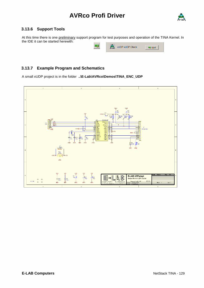
AVRco Profi Driver
E-LAB Computers NetStack TINA - 129
3.13.6 Support Tools
At this time there is one preliminary support program for test purposes and operation of the TINA Kernel. In the IDE it can be started herewith:
3.13.7 Example Program and Schematics
A small xUDP project is in the folder ..\E-Lab\AVRco\Demos\TINA_ENC_UDP

AVRco Profi Driver
130 – USB Interface E-LAB Computers
3.14 USB Interface Introduction Embedded systems ofeten need a connection to a host, eg a PC. For a long time this was the serial interface through a COMport/UART. Todays PCs and mostly Laptops and Notebooks often don’t provide a COMport. It is expected that every peripheral device provides an USB interface. There are several solutions to realise an USB connection with an AVR:
1. a FTDI Chip on board which builds a vitual COMport an the PC. On the side of the AVR the FTDI behaves like a MAX232. Disadvantage: board place, costs and a possible conflict with COMports on the PC side.
2. HID and USB-AVRs. Simulation of a mouse or a keyboard on the AVR side. Advantage: cheap, a minimal cost on the PC side. Drawback: weak properties of the system.
3. CDC and USB-AVRs. The system provides a virtual COMport on the PCdar, similar to FTDI. Advantage: only an INF file must be constructed for the PC side, but this is absolutely not trivial. Deawback: conflict with other COMports because it is not sure that the device is always located on the same COMport and so it must always be searched.
4. Unique USB and USB-AVRs. This is the most elegant but also the difficultiest way for an USB connection. Here the AVR is recognised as an absolutely new and unique USB device. Drawback: a DLL, a SYS and an INF file for the PC must be build and procided. Very difficult. The communication on the PC is much more complex compared with the other solutions. Advantage: all features of the USB can be used: sending commandos through the controlpipe (Endpoint0), upto 4 date pipes, 2xdownstream, 2xupstream, flexible packet sizes. High speed, upto 200kByte/sec with controlling handshake! All drivers and files for the PC are build by two mouse clicks!
The implementation provided here use the unique interface described in 4. On the AVR side the AVR-USB driver of the AVRco system provides powerful but simple functions. All AVRs with internal USB interface are supported. Control Pipe. The Control Pipe (endpoint0) is used to force a real hardware reset on the AVR send by the PC. Furthermore the Control Pipe can pass private commands to the AVR. There this date is passed via a Callback function to the AVR application.
Simple Interface. There are two 8byte sized pipes provided, endpoint3 and endpoint4 (1xUpstream, 1xDownstream). These serve for an asynchron communication without any feedback etc. The AVR places these 8 bytes into the RxBbuffer and informs the main program. What should be happen with this data must be decided by the main. Another 8byte package from the PC into this pipe then overwrites this buffer without waiting that the main has fetched the previous package or not. Similar is true with the Upstream. The PC can continously read the 8byte TxBuffer without knowing whether it is updated by the main or not. The AVR main is only informed that the Host has read the buffer. The important data transfer must be accomplished through the endpoint1 and endpoint2. PacketDown: The Host sends upto 64bytes or multiples of it. The total packet size is send via control-pipe to the AVR.The AVR driver raises a flag that data will come in and the count of bytes. The AVR main must continously poll this flag to avoid a timeout on the Host. These datas now must be fetched by calling a driver funktion. This pipe stays locked until all data is read. So the Host can’t send any data at this time. The Host is able to send packets > 64bytes. The driver in the Host splits this big block into packet sizes which the AVR can handle. The called AVR driver function now reads the data until all data (pronounced via the control-pipe) is transferred. Of course the AVR must be able to read/place bigger packets in one piece into the RAM. PacketUp: Here the Host reads upto 64bytes or multiples of it. The total packet size is send via control-pipe to the AVR.The AVR driver now raises a flag that the Host will read data and the passes the byte count. The application must poll this flag and the pass them to the driver via a driver function. This pipe stays locked until all data is sent. So the Host can’t start a new read in this time. The Host is able to read packets > 64bytes. It then splits big packets into 64byte blocks. Of course the AVR must be able to send larger data packets in one piece.
By this treatment an extremely secure data transfer is installed, of course somewhat of cost of the speed. Upto 200kByte/sec can be achieved.

AVRco Profi Driver
E-LAB Computers USB Interface - 131
StreamDown Data pump. T.B.D. StreamUp Data pump. T.B.D.
3.14.1 Import of the USB Driver
As always in the AVRco System the driver must be imported: Import SysTick, USBport, WatchDog, ...; Because the USB driver needs a Time-Out the SysTick must be imported. The WatchDog is used for a real Hardware Reset.
3.14.2 Definition of the USB Driver
The USB driver needs some essential Defines which determine the way/infos the driver connects to the Host. Define ProcClock = 16000000; // Hertz SysTick = 10; // msec StackSize = $0080, iData; // min size FrameSize = $00C0, iData; // min size WatchDog = 7;
USBvid = 9876; // Vendor-ID USBpid = 1234; // Product-ID USBprodRel = 4321; // Product-Release USBmanufact = 'E-LAB Computers'; USBprodName = 'EvaBoard USB128'; USBcurrent = 200; // max current consumption USBsernum = 2143; // Product serial number
ProcClock the clock must be either 8 or 16MHz. SysTick used for internal TimeOuts. USBvid is the Vendor/Manufacturer ID. Provided from the USB.org (costs). USBpid is the Product ID. Can be any. USBprodRel is the actual version of the product. Can be any. USBmanufact is the name of the producer as a string. USBprodName is the name of the product as a string. USBcurrent is the expected current consumption through the USB cable in mA. USBsernum is the serial number of the device. All items are mandatorial though only USBvid and USBsernum are really minded by the Host.
If the serial number of all devices of this manufacturer and type are constant then there is no action when a new device of this kind is connected. Only once at the very first time the PC asks for a driver. If the srial number changes so with each new serial number a question for a correct driver is raised.
3.14.3 Exported Types
type tEp3_4Buf = array[0..7] of byte; This array type has to be used for reading and writing of the 8byte data of the Simple Interface.

AVRco Profi Driver
132 – USB Interface E-LAB Computers
3.14.4 Callback Function
The Host program is able to send some private commands through the Control Pipe (endpoint0). To handle this in the device the main must provide a Callback Function. The address of this function must be passed to the driver: Procedure myUserProc(x : byte; v : word); begin // ... // this function returns with user defined commands in x and v send by the host end; … USBsetUserProc(@myUserProc); If myUserProc is not present or not passed to the driver by USBsetUserProc then there is no callback and incoming commands are ignored. Attention: Callbacks are always started out of an interrupt. Because of this large, time consuming operations like Float are taboo. They disable interrupts too long. Driver calls (LCD, COMport etc.) are absolutely forbidden. This can lead to a total crash or at least blockade of the system.
3.14.5 Exported Functions and Procedures
3.14.5.1 Common Functions Procedure USBsetTimeOut(to : byte); Within the transmit and receive operations a blockade can occur for example by external distortions, cable break etc. To remove this a timeout is decremented by the SysTick. With this procedure this value must be set in SysTicks 0..255 at startup. Function USBgetTimeOut : boolean; If the function USBsetTxBuf or the function USBgetTxBuf returns with the result“0“ then a Timeout error can be the reason. The driver then should be asked for a TimeOut. This call also resets the TimeOut. Now it is the job of the application to proceed in a proper way. Procedure USBsetUserProc(@myUserProc); The address of the User Function myUserProc in the Main is passed to the driver. If the Host sends a user defined command through the Endpoint0 (Control) the procedure myUserProc is called and in the parameters x and v the received commands are given. Function USBinit : boolean; The USB hardware becomes initialised, also some local parameters. After this the driver and the AVR hardware ready to process the for the login interrogation of the Host and do some replies. If successful then the PC makes a Ding-Dong. Procedure USBclose; The USB interface of the AVR is closed. The PC/Host notifies this and also closes the corresponding interface (Ding-Dong). If the interface must be re-opened the a new USBinit must be excuted. Function USBconnected : boolean; The state of the USB interface is returned. A false is returned if
a. an electrical problem (eg. cable) exists. b. an USBclose was executed. c. no USBinit was executed.

AVRco Profi Driver
E-LAB Computers USB Interface - 133
3.14.5.2 Simple Interface Function USBgetRxState8 : byte; The function returns how often (RxCount) the Host has rewritten the internal RxBuf8. Please note that the Host can have over written this buffer several times until this function is called. If the result is 0 then there is nothing new there. With > 0 the buffer is overwritten at least one time. Procedure USBgetRxBuf8(var buf : tEp3_4Buf); If the function USBgetRxState8 returns with a resultat <> 0 then the RxBuffer in the driver contains 8 new bytes. These are always the 8 bytes rewritten by the Host the last time. This procedure now transfers these 8 bytes into the buffer in the application where var buf points to. The corresponding RxCount is reset to 0. Function USBgetTxState8 : byte; The function returns how often (TxCount) the Host has read the internal TxBuf8. Please note that the Host can have read this buffer several times. If the result = 0 then the TxBuffer was read at least one time by the Host. If > 0 then the TxBuffer was not read after the application has filled it the last time. Procedure USBsetTxBuf8(buf : tEp3_4Buf); If the function USBgetTxState8 returns with a 0 zurück the Host already had read this buffer. The procedure now writes 8 bytes out of the application area pointed by buf into the driver’s TxBuffer and increments the corresponding TxCounter in the driver. If the Host now reads this buffer in the driver this counter will be set to 0. In the PacketMode the Host informs the Slave before about the total amount of bytes reading or writing a packet. These values are stored in the driver and informs the application by a request about the direction (up/down) and also of the necessary byte count.
3.14.5.3 PacketDown Function USBgetRxState : word; The application should continously poll this function which returns the Rx-state of the PacketMode if a Host write is expected. If the result is <> 0 then the function getRxBuf must be called to avoid a Timeout in the Host. Function USBgetRxBuf(p : pointer; len : word) : word; The incoming Host packet is returned from the driver. Please note that there is no intermediate buffering in the driver. The data is directly read out from the endpipe. The pointer parameter defines the target address. Normally the read count (len) should be the same as getRxState returns. Of course the destination memory must be able to fetch all these bytes. Because of this the bytecount limit is passed in „len“. If len is smaller as the expected count then the transfer is stopped when „len“ is reached. So overwriting of variables etc. is not possible which can result in a crash. As the result the effective byte count is returned.
3.14.5.4 PacketUp Function USBgetTxState : word; This function must be used by the application to continously poll the Tx-state of the PacketMode if a read is expected. If the result is <> 0 then the setTxBuf function should be called to avoid any timeout on the Host. Function USBsetTxBuf(p : pointer; Len : Word) : word; The Host fetches a packet directly from the driver. Please note that there is no intermediate buffering in the driver. The date is directly written into the endpipe. The pointer parameter defines the source address in the application. Normally the write count (len) should be the same as getTxState returns. Possibly there are less bytes to send by the application. So the real bytecount must be passed in „len“. If len is smaller as the expected count then the transfer is stopped when „len“ is reached, otherwise when the „getTxState“ result is reached. As the result the effective byte count is returned. If there is nothing to send a “0“ can be passed in „len“.

AVRco Profi Driver
134 – USB Interface E-LAB Computers
3.14.5.5 StreamDown T.B.D.
3.14.5.6 StreamUp T.B.D.

AVRco Profi Driver
E-LAB Computers USB Interface - 135
3.14.6 AVR Implementation
program USB_Test; { $NOSHADOW} { $WG} {global Warnings off} Device = 90USB128, VCC=4.5; { $BOOTRST $0F000} {Reset Jump to $0F000} Define_Fuses // Override_Fuses; NoteBook = B; COMport = USB; Supply = 5.0, 100; LockBits0 = []; FuseBits0 = []; FuseBits1 = [SPIEN, JTAGEN, OCDEN]; FuseBits2 = []; ProgMode = JTAG; Import SysTick, USBport, WatchDog, BeepPort, SerPort; From System Import ; Define ProcClock = 16000000; {Hertz} SysTick = 10; {msec} StackSize = $064, iData; FrameSize = $064, iData; WatchDog = 7; SerPort = 19200; BeepPort = PortE, 5; USBvid = 9876; // Vendor-ID USBpid = 1234; // Product-ID USBprodRel = 4321; // Product-Release USBmanufact = 'E-LAB Computers'; USBprodName = 'EvaBoard USB128'; USBcurrent = 200; // max current consumption USBsernum = 2143; // Product serial number Uses uAVR_USB;

AVRco Profi Driver
136 – USB Interface E-LAB Computers
Implementation {$IDATA} {--------------------------------------------------------------} { vars } var USBrxBuf : array[0..255] of byte; USBtxBuf : array[0..255] of byte; USBrxBuf8 : tEp3_4Buf; USBtxBuf8 : tEp3_4Buf; {--------------------------------------------------------------} { functions } Procedure myUserProc(x : byte; v : word); begin // ... end; {--------------------------------------------------------------} { Main Program } {$IDATA} begin USBsetUserProc(@myUserProc); USBsetTimeOut(100); USBinit; EnableInts; BeepOutHL; WriteLn(SerOut, 'E-LAB USB Test'); While not USBconnected do BeepClick; SerOut('?'); mDelay(300); endwhile; WriteLn(SerOut); WriteLn(SerOut, 'connected');

AVRco Profi Driver
E-LAB Computers USB Interface - 137
loop if USBgetRxState8 > 0 then USBgetRxBuf8(USBrxBuf8); endif; if USBgetTxState8 = 0 then USBsetTxBuf8(USBtxBuf8); endif; if USBgetRxState > 0 then USBgetRxBuf(@USBrxBuf, 256); endif; if USBgetTxState > 0 then USBsetTxBuf(@USBtxBuf, 256); endif; if SerStat then case SerInp of 'D','d' : USBclose; // detach, disconnect | 'C','c' : USBinit; // re-init | 'S','s' : if USBconnected then SerOut('c'); else SerOut('x'); endif; // status, connected | else BeepOut(1000, 10); SerOut('?'); endcase; endif; endloop; end USB_Test. This demo and test program can be found in the installation in ..\AVRco\Demos\EvaBoard128USB\
AVRco Profi Driver
138 – USB Interface E-LAB Computers
3.14.7 Host/PC Implementation
USB interfaces are pure Master/Slave systems like I2C or SPI. The PC is always the Host/Master and the device is always the Slave. A Slave never can send data to the Host, but the Host must read data out of the Slave. This must be taken in account with each communication between Host and Slave. An USB device always needs a suitable driver on the Host/PC side. These maybe already existing ones like HID for mouse or Keyboard. Here there is no need for additional drivers. Then there is the mostly unknown and rarely used CDC interface (virtual comport) which only needs a specific INF-File. Proprieretary devices like printers or the E-LAB programmer always need a complete driver set consisting of a SYS-File, INF-File and sometimes a DLL. The AVRco USB implementation for AVRs also need these three driver parts. Because the constructions of them, mainly the SYS file, needs tremendous knowledge the AVRco system provides a so called generic driver. It can be configured with parameters for nearly every device. This is the libUSB system. It provides a complete configurabel driver set, including the automatic creation of the INF file. This text file contains the description of the driver and the capabilities of the device. The manual creation of such an INF-Files needs a huge knowhow and can be a nightmare for unexperienced users. When creating a Windows application for USB controlled AVRco devices the DLL build by the libUSB system must be used. This DLL provides all necessary interface functions. The DLL functions used by the included Delphi application „USBtester“ are provided by the Unit „LibUSB.pas“. And there are much more. Used functions are:
3.14.7.1 Initialisation etc. Procedure usb_init; Function usb_find_busses : longword; Function usb_find_devices : longword; Function usb_get_busses : pusb_bus;
3.14.7.2 Device specific Function usb_open(dev : pusb_device) : pusb_dev_handle; Function usb_close(dev : pusb_dev_handle) : longword; Function usb_set_configuration(dev : pusb_dev_handle; configuration : longword) : longword; Function usb_claim_interface(dev : pusb_dev_handle; iinterface : longword) : longword; Function usb_release_interface(dev : pusb_dev_handle; iinterface : longword) : longword;
3.14.7.3 Support Function usb_get_descriptor_by_endpoint(udev : pusb_dev_handle; ep: longword; ttype : byte; index : byte;
var buf; size : longword) : longword; Function usb_get_descriptor(udev: pusb_dev_handle; ttype: byte; index: byte; var buf; size: longword): longword; Function usb_get_string_simple(dev: pusb_dev_handle; index: longword; var buf; buflen: longword) : longword;

AVRco Profi Driver
E-LAB Computers USB Interface - 139
3.14.7.4 Data Transfer Function usb_control_msg(dev : pusb_dev_handle; requesttype, request, value, index : longword;
var bytes; size, timeout : longword) : longword; This function must be used to send commands through the Control-Pipe (endpoint0). The following parameters are mandatory to send „private“ commands and data to the Slave: requesttype = $40 request = $00 value is the actual command index is an optional word parameter bytes and size are only used for reading data out of the controlpipe. Not used here timeout is in msec The commands (value) 0..15 are reserved for the AVRco system. With the ControlMessage/endpoint0 it is possible to send several commands or the transfer mode can be selected. tmsg_type = (msgReset, msgTest, msgPacket, msgStream, msgDownLen, msgUpLen, msgUser = $10); msgReset forces a hardware Reset in the Slave (AVR). msgTest switches Host and Slave into the test mode. Any count of 64byte packets can be send
and received. In the AVR the packets are not processed. This mode serves to check the maximum transfer rate.
msgPacket is the standard working mode. In addition the commands msgDownLen or msgUpLen must be send bevor each receive or transmit to inform the slave about the size of the next packet.
msgStream sets the stream mode. Not implemented yet! msgDownLen must precede in the Packet Mode each usb_bulk_write. Index contains the bytecount. msgUpLen must precede in the Packet Mode each usb_bulk_read. Index contains the bytecount. Commands 16..255 (msgUser+x) can be used in the user application and are processed by a Callback function in the AVR. The index parameter is optional. See the “RESET” example in the Delphi source. Function usb_bulk_write(dev: pusb_dev_handle; ep : longword; var bytes; size, timeout:longword): longword; This is the the actual tx-function. Data is send to endpipe1 or endpipe3. Parameter: ep = endpoint1 or endpoint3. Endpoint3 can only receive 8 byte packets! bytes = Buffer which contains the packet to send size = count of the bytes to send. Any count with endpoint1, but the Slave must be able to receive and store
this packet in one piece. This means ist Rx-Buffer must be large enough. On the PC the packet size can be random. They are internally split into 64 byte sized blocks/packets and then send. The result of the function is the total transmitted byte count. If the Slave is unable to read all bytes because of memory limitations, the result is always the count of the bytes send. Will be fixed later.
With endpoint3 always 8 bytes must be send! Here the current mode is don’t care.
Function usb_bulk_read(dev: pusb_dev_handle; ep: longword; var bytes; size, timeout:longword): longword; Das ist die eigentlich Empfangs Funktion. Daten werden von der endpipe2 oder endpipe4 abgeholt. Parameter: ep = endpoint2 or endpoint4. Endpoint4 can only transmit 8 byte packets! bytes = Buffer which must contain the received data size = count of bytes to receive. Any count with endpoint2. But the Slave must be able to send this packet in
one piece. Means ist tx-buffer must be large enough. On the PC the packet size can be random. They are fetched in 64byte blocks and then returned in one packet. The result of the function is the total received byte count.
With endpoint4 always 8 bytes must be received! Here the current mode is don’t care.

AVRco Profi Driver
140 – USB Interface E-LAB Computers
3.14.8 Testprogram in the IDE PED32
The AVRco installation provides a test program „USBtester“ which can be started by the left menu. The the form below is shown:
After selecting a device the working dialog is shown.
Some working modes can be set and transfers can be started. The source of this Delphi program can be found in the installation directory in ..\AVRco\IDE\USBtester\

AVRco Profi Driver
E-LAB Computers USB Interface - 141
3.14.9 Support Tools
Inf-Wizard Start Creating the necessary SYS, INF and DLL files for the Host/PC is an enormous challenge for the developer. For many not doable without the right knowhow and experiences. Therefor AVRco system contains a tool which exactly does this for you!. It will be started in the menu above. Attention: The AVR Device must be connected and working properly! Any driver isn’t necessary at this time. Please select only the device you have build! Accidently selecting the wrong device and installing it will result in a failure of this (wrong) device.Maybe it will never work again!!
The next step is checking the data and parameters of this device drivers. With „Next“ the driver files are build and stored. Optionally this driver can directly be installed on the current system. Then this device is ready to operate. The Wizard generates several files:
But for the enduser only these are important:
These files and directories must be given to the enduser exactly as they are (directories etc).
If such a device is connected to a Host the first time the PC ask for a suitable driver. The this INF-File must be selected. The rest will be done automatically. Never give the away the Inf-Wizard. Inexperienced user can destroy or cripple the whole PC system.

AVRco Profi Driver
142 – USB Interface E-LAB Computers
3.15 USB-CDC Virtual Comport XMega The implementation of an USB driver can be very complex on both sides, the PC and AVR. With many applications a very simple interface like a Comport is sufficient. But this is not always present in every PC. Here a virtual Comport can help, which is placed over the USB interface on both sides. In the PC a CDC is already implemented. Only a correct INF file is necessary. On the AVR side much more effort is necessary. But this effort is completely contained in the SerPortCDC driver. So the programmers job is limited tot he handling oft he serial interfaces of both sides, AVR and PC. On both sides there are no USB operations to be programmed. But the correct INF file for the PC must be created by the user.
3.15.1 Import of the CDC driver
As usual with the AVRco system the driver must be imported: Import SysTick, SerPortCDC, ...; //From SerPort import SerPortSelect; // optional Because the CDC driver needs some timeouts, also the SysTick must be imported.
3.15.2 Definitions of the CDC driver
The CDC driver needs some defines fort he used USB connection tot he PC: Define // The XMegas don't provide any Oscillator fuses. // So the application must setup the desired values // possible OSC types: extXTAL, extClock, ext32kHz, int32Khz, int2MHz, int32MHz // XMega USB must use the internal 32MHz OSC. So the system must use the 2MHz OSC OSCtype = int2MHz, PLLmul = 16, prescB = 1, prescC = 1; SysTick = 10; {msec} StackSize = $0080, iData; FrameSize = $00C0, iData; USBmanufact = 'E-Lab Computers'; // max 31 bytes USBprodName = 'Serial CDC-USB'; // " " USBpid = 77; // CDC USBvid = $ABCD; USBprodRel = 001; USBcurrent = 500; // USBvBUS = PortB.4; // port and pin, optional // SerPortCDC = timeout; // SysTick timouts, optional RxBufferCDC = 64, iData; // min 64, max 254 TxBufferCDC = 100, iData // min64, max 254; uses uXMega_CDC; These USB defines are mandatory and the user must provide the correct data, for example USBvid. The import of the Unit uXMega_CDC also is mandatory. This unit provides all necessay USB functions. The User application uses the CDC device like any other serial interface. Most of the AVRco contained SerPort functions are also supported here.

AVRco Profi Driver
E-LAB Computers USB Interface - 143
3.15.3 Exported Functions
Procedure CDCopenPort; Initialises and opens the CDC port. Procedure CDCclosePort; Closes the open CDC port. Function CDCportValid : boolean; Returns a true if the CDC port is valid and ready to operate. Procedure SerOutCDC(ch : byte|char); Function SerInpCDC : byte|char; Function SerInp_TOCDC(var : byte|char; timeout : byte) : Boolean; Function SerStatCDC : boolean; writeLn(SerOutCDC, st); Procedure SerOutBlock(UsartCDC; location: type); Procedure SerOutBlock_P(UsartCDC; p : pointer; count : word); Procedure SerInpBlock(UsartCDC; var location: type); Function SerInpBlock_TO(UsartCDC; var location: type; timeout : byte) : Boolean; Procedure SerInpBlock_P(UsartCDC; ptr : pointer; len : word); Function SerInpBlockP_TO(UsartCDC; ptr : pointer; timeout : byte) : Boolean; Procedure FlushBuffer(RxBufferCDC); Procedure FlushBuffer(TxBufferCDC); Function PipeStat(TxBufferCDC) : byte; Function PipeFull(RxBufferCDC) : boolean;
For more common info about the SerPort functions please see the AVRco Standard Driver Manual Attention: A CDC port (Virtual ComPort) basically works like an UART. This means it is possible to overrun buffers. So for security reasons the PC should not send blocks > RxBufferSize bytes. Basically if the AVR can not readout the full RxBuffer in time then incoming bytes are ignored! With sending to the PC all data is lost when the connection is down (cable problem etc). Therefor the function “CDCportValid“ should be called sporadically to see whether the CDC is still valid and working. Besides this it makes sense to implement a simple handshake. One side sends data and then waits until the receiver responds with an „ok“ or similar before the next data can be send. The included INF file fits to the demo. If USBvid or USBpid is changed in the source also the INF file must be changed accordingly! Program example: A sample program can be found in the folder ..\E-Lab\AVRco\Demos\XMega_USB_CDC A sample INF file for the PC is also located there.

AVRco Profi Driver
144 – USB Interface E-LAB Computers
3.16 AES Encrypt/Decrypt XMega The error and theft protection in the data transmission becomes more and important. A big improvement here ist he encryption of any data type with AES. This uses an 128bit key which is perfectly not breakable. The AVRco system then uses the AES hardware which is present in the most XMegas. It is extreme fast so that time losses for an encryption are less important. With AES there are two different modes, the ECB and the CBC. The ECB is somewhat simpler but also less secure than CBC. ECB Always a 16byte block becomes encrypted or decrypted. The AES_Init must only called once at start. The key will not be changed. So it must be vlear that identical blocks are always decrypted in the same way and result. If one bit in a block is wrong then only this block is wrong after a decryption! CBC Also here always 16byte blocks are decrypted. The AES_Init must only be called once at the start of a series of consecutive 16byte blocks. The internal key then get changed after each cycle dependent oft he contents oft he previous block. If only one or more bits are wrong then all following block are decrypted wrong. A hacking then is absolute impossible.
3.16.1 Import of the AES driver
As usual with AVRco the driver unit must be imported: Uses uXMegaAES, ...;
3.16.2 Expored Functions
The driver exports some functions: Function AES_Init(Key, InitVector : Pointer) : boolean; It must be called once bevor the start of an AES session. With the ECB mode the InitVector must be nil. With CBC the InitVector must have a value. With ECB the key and with CBC the key and vector must point to a 16byte structure. Function AES_DecryptECB(Data : Pointer; count : word) : boolean; This funcktion decrypts a datablock. Data must point to a block which must be a multiple of 16. Also count must be a multiple of 16. The resulting data then is still in the data block. Function AES_EncryptECB(Data : Pointer; count : word) : boolean; This function encrypts a datablock. Data must point to block which must be a multiple of 16. Also count must be a multiple of 16. The resulting data then is still in the data block. Function AES_DecryptCBC(CipherBlock, PlainBlock : Pointer; count : word) : boolean; This function decrypts a datablock. CipherBlock (source) must point to block which must be a multiple of 16. PlainBlock (destination) must point to block which must be a multiple of 16. The destination block (PlainBlock) size must at least have the size oft he source block. Also count must be a multiple of 16. After the decryption the decrypted data is in the PlainBlock. Function AES_EncryptCBC(PlainBlock, CipherBlock : Pointer; count : word) : boolean; This function encrypts a datablock (PlainBlock -> CipherBlock). Similar to AES_DecryptCBC. Attention It must be clear that the Keys and Vectors must be absolutely identical on both sides of the communication.
Example program: an example is in the directory ..\E-LAB\AVRco\Demos\XMega_AES

AVRco Profi Driver
E-LAB Computers Wiegand Interface - 145
3.17 Wiegand Interface
3.17.1 Introduction
The Wiegand Data Interface is one of the most widespread interfaces in access control industry but it is completely unknown in PC world. Consequently, experimenting on access control devices or even simple checking whether data preprogrammed by vendors in access control tags suit the purchaser's order needs at least an access controller if not the whole access control system. The ACRco system supports the 2-line Wiegand controllers/sensors. The most used versions, the 26bit and 37bit protocol types are implemented. The driver is completely interrupt controlled.
3.17.2 Interface
A typical Wiegand controller has two data lines, DATA0 and DATA1. Both are idle log1 = high. The voltage of the “1” can be between 5V and 24V, dependend of the operating voltage of the device. If this voltage is higher than the uC operating voltage the two lines must be clamped in the high state to the CPU’s operating voltage by some diodes for example. The information send by the device comes with “low” pulses on the two lines. The telegram consists of pulses on both lines. One line contains the zeros and the other carries the ones. A pulse lasts about 50usec, the pause between two pulses is 2msec. The pause between two consecutive telegrams is about 200msec. Because of these very long times it makes no sense to operate the Wiegand driver with any kind of polling. Using interrupts and timers become mandatory.
The best way is to use two port pins to read the two data lines and each low state of any line must fire an interrupt. With an AND gate both lines can generate a low pulse at the INT pin. This AND gate can also be implemented with two switching diodes, 1N4148 for example.
Please note that the low pulses are very short, 50uSec. If the global interrupt is disabled too long the used interrupt maybe delayed in a way so that the reading of the port pins returns the idle state of the lines. The result of this can be missing telegrams or parity errors. Worst case there will be no valid reception. In common: as with all interrupt driven systems avoid heavy duty jobs in interrupt service routines. Otherwise you will get an instable system.

AVRco Profi Driver
146 – Wiegand Interface E-LAB Computers
3.17.3 Import of the Wiegand Driver
As usual with AVRco the driver must be imported: Import SysTick, WiegandPort, ...; Because the Wiegand driver needs some timeouts etc. the import of the SysTick is necessary.
3.17.4 Defines of the Wiegand Driver
The Wiegand driver also needs some defines, which Interrupt and port pins must be used. Define ProcClock = 16000000; // Hertz SysTick = 10; // msec StackSize = $0080, iData; // min size FrameSize = $00C0, iData; // min size WiegandPort = INT0, PINA, 2, 3; // Wigand The first parameter of the Wiegand Define is the external interrupt to be used. Please note that this interrupt must support the “negative edge triggered” mode. Not every mature AVR supports this. The second parameter defines the IO-port where the two lines are connected while the last two define the port pins used for it. The two pins can be interchanged if the resulting number of a read-out is inverted, $00 -> $FF
3.17.5 Exported Functions
The driver exports two function which must be used for successful operation. WiegandGetState This function must be called before any data can be read. It returns a true when any data frame is available. But it doesn’t check the received data for validity. Function WiegandGetState : boolean; WiegandGetData With calling this function the data is transferred out of the system buffer into the user buffer. While transferring the data the parity bits are checked. If the frame is valid (no parity error) the function returns the frame type, either a 26 or a 37. Regardless of the result the function invalidates the internal buffer so the next call of WiegandGetState returns a false until a new frame was received. Function WiegandGetData(p : pointer) : byte; Because the receiving of a data frame is done in interrupts it makes no sense to compute and check the parity bits there. This is done in WiegandGetData. So the Function WiegandGetState returns always a true if a complete frame was received and doesn’t care about the parity bits. The function WiegandGetData needs a pointer as the passed argument. This pointer must point to a RAM structure of any kind but with the size of 5 bytes. For example an array[0..4] of byte will be sufficient. The function then transfers the internal stored frame into the area provided by the user where the pointer points to.
3.17.6 Example Program
An example program can be found in the directory ..\E-LAB\AVRco\Demos\Wiegand
AVRco Profi Driver
E-LAB Computers Incremental Encoder IncrPort8 - 147
3.18 Incremental Encoder Driver IncrPort8 The AVRco system provides 3 different driver for incremental/position encoders. The main differenzes are in their pulse processing. The IncrPort4 driver cyclically scans up to 4 encoder channels using one timer and one port but is limited by its scan rate. Scanning means a constant system load so the scan rate must be choosen so that the system will not run into an overload. This limits the max. possible input pulse rate. So it is not usable for high speed encoders. The implementation of the IncrPort8 driver doesn’t show these limitations because only a phase change of an input signal pair generates an interrupt. Of course also here the max. possible pulse rate is given by the processor speed and the interrupt processing time. As with all high-speed applications with interrupts long interrupt disable times must be avoided, otherwise the delay of a PCint can lead to errors. This implementation can use any input port and upto 8pcs 2-phase sensors can be connected. It is required that the two lines of a sensor must be connected to the same port. The CPU must support the PIN-Change-Interrupts (PCint). The portpins used mus be in input mode. Quadrupling of the input pulses (quadrature) is always activated. Unused pins can be used for other jobs. The driver uses the PIN Change Interrupts for reading and processing the channels. Because of this each longer interrupt disable can result in erroneous results. A continous polling of the channels by the application can also lead to problems with the interrupt system because each read access also includes an disabled interrupt throughout this access.
3.18.1 Imports
The driver must be imported as usual with AVRco. Import …, IncrPort8, ..; The resolution (16 or 32bit), the desired PCints and the number of encoders have to be defined. Please note that used port pins are fixed by the PCint number define of PCintxx.
3.18.2 Defines
Define ProcClock = 16000000; {Hertz} StackSize = $0020, iData; FrameSize = $0040, iData; IncrPort8 = 32; // resolution 16 or 32 bits IncrChan0 = PCint00, PCint01; // PCINT ports used = B.0 B.1 IncrChan1 = PCint10, PCint11; // PCINT ports used = C.2 C.3 …

AVRco Profi Driver
148 – Incremental Encoder IncrPort8 E-LAB Computers
3.18.3 Functions
There are 8 different functions exported. The parameter chan counts from 0 (0..3). Procedure IncrCount8Start(chan : byte); After a Reset or PowerOn the driver does not run. Each channel must be started with this procedure. This procedure does not change any counter states. Procedure IncrCount8StartAll; This procedure starts all channels. Procedure IncrCount8stop(chan : byte); Stops all channels. The counter states are not changed. Procedure IncrCount8stopAll; Each channel can be stopped. The counter states are not changed. Function GetIncr8Val (chan : byte) : integer [longint]; This function returns the actual internal counter value of chan as an integer if a 16bit counter is defined. The result is a longint if a 32bit counter is defined. The internal value is not changed by a read out. The vreadout of each channel is done with a disabled interrupt! Procedure ClearIncr8Val(chan : byte); This procedure resets the internal counters of chan. Procedure ClearIncr8All; This procedure resets all absolute and relative internal counters. Procedure SetIncr8Val (chan : byte; val : integer [longint]); This procedure resets the absolute internal counter at chan to “val”. Remarks: This driver is interrupt controlled. If the general interrupt is disabled too long faulty results are possible. If the parameter chan is passed by the functions it is always compared to the channel count defined with IncrPort8. If this value is out of range the function does nothing and returns a zero if necessary. The channel parameter chan counts from zero. Example program:
an example is in the directory ..\E-LAB\AVRco\Demos\ Increment8

AVRco Profi Driver
E-LAB Computers SLIP Port - 149
3.19 SLIP Driver SLIPport1..4 / SLIPportC0..F1
Networks basically work with so called packets or frames. This is a block of data which is framed (limited) by a start and end condition. This is absolutely necessary to have a secure data transmission. These frame limiters can be constructed in different ways. For example a well defined pause between two data blocks like ModBUS RTU or there are special control bytes if the data is plain ASCII (A..Z, a..z, 0..9) like (ModBUS ASCII). With more complex protocols like CAN, Ethernet, I2C/TWI etc. the framing is explicitely implemented in the driver hardware. Without such framing it is a difficult task to identify incoming frames on the receiver side. But also with timeout-controlled protocols this is not trivial. On both sides timers and interrupts are involved to avoid unexpected time slots or timeouts. With ASCII protocols there is a big overhead on both sides to convert binary data into ASCII chars (e.g. HEX) and vice versa. But with simple bit-serial interfaces like UARTs and SPI building frames, clearly recognizing them is a huge problem. For this purposes there is a powerful protocol called SLIP.
Serial Line Internet Protocol The word “Internet“ can easily replaced by “Interchange“ or “Interface“ because SLIP basically and only defines the frame-start and frame-end handling. All the other stuff must be handled by a processing layer above SLIP. SLIP provides a secure recognition of the frame start and frame end condition and extracts the pure data packet for the application. The data contained in the packet can be of any type and is not changed or analysed by SLIP. The AVRco system provides a SLIP implementation in conjunction with the serial interfaces (UARTs) 1..4 where they are present in the CPU. Contrary to the SLIP FUNKTION (Standard Driver Manual), which is only a Shell around the Rx- and TxBuffer, this driver completely runs autark. It doesn’t use any buffers but reads and writes exclusively from/to the buffers which the application must provide. The advantage is a more compact code and the possibility to use a handshake, address comparison and checksums.
Upto 4 ports (SLIPport1..4) can be imported and used at the same time, depending of the UART count in the used controller. XMega upto 8 SLIPports (SLIPportC0.. SLIPportF1). RS485 Line Driver If the corresponding SerPort uses the RS485 mode then the driver handles this automatically without intervention of the application. The driver provides several operation modes:
1. Simple communication. SLIP packets are transceived and received, without handshake, address, checksum etc.
2. With checksum. The Tx-driver appends a checksum as the last byte. The Rx-driver then builds an own checksum out of the received data and compares it with the received checksum. The result of the compare becomes the Rx state which the Rx application gets by reading of the Rx state.
3. With handshake. The Tx-driver sends a packet and waits until a timeout has occured or the receiver sends an acknowledge packet. Please note that this is similar to a half duplex operation. The sender can read the result of an ACK or timeout. The acknowledge then can have several states.
4. With address. With this mode a single-Master/multi-Slave network can be implemented, for example based on RS485. The Tx-driver at first sends a byte which is the desired slave address. The Rx-driver of all slaves read this address and if it is the same as its internal address the packet is accepted. Otherwise it becomes discarded. There are upto 190 addresses. The address 0 should be reserved for the Master. The addresses 190..254 are reserved for internal use and must never be used by the application. The address 255 is the broadcast address which is accepted by all Slaves. But such a packet will never initiate an acknowledge from any Slave.
All operation modes can be combined in any way. So it is possible to install a very secure and reliable communication with Handshake+Checksum. If necessary the application can do some retries in case an error occured.

AVRco Profi Driver
150 – SLIP Port E-LAB Computers
With the combination of all options it is possible to build a very flexible RS485 netzwork. In contrast to the LAN network, where the Multiprozessor Bit of the AVR is used to identy the start of a frame, here it is possible to include also a PC or other controllers/electronics into the network, as far as a proper SLIP driver is installed there.
3.19.1 Imports
The driver must be imported as usual with AVRco. Import SysTick…, SLIPport1, ..; // SLIPport2, SLIPport3, SLIPport4 XMega Import SysTick…, SLIPportC0, ...; // SLIPporC1, SLIPportD0, SLIPportD1, SLIPportE0, SLIPportE1... The SysTick is needed for the timeouts. Dependend on the CPU type there are upto 4 UARTS which can be selected by an Import. SLIPport1 => UART0 etc.
3.19.2 Defines
Define ProcClock = 16000000; {Hertz} SysTick = 10; StackSize = $0020, iData; FrameSize = $0040, iData; SLIPport1 = 19200; // SLIPport2, SLIPport3, SLIPport4 // SLIPportCtrl1 = PortA, 0, positive; // optional RS485 line driver control … XMega Define ProcClock = 16000000; {Hertz} SysTick = 10; StackSize = $0020, iData; FrameSize = $0040, iData; SLIPportC0 = 19200; // SLIPportC1, SLIPportD0, SLIPportD1... // SLIPportCtrlC0 = PortA, 0, positive; // optional RS485 line driver control …
With a RS485 line driver the direction (tx/rx) of the driver chip must be controlled by the SLIP driver. In order to import this property the controlling port, portbit and active level must be defined.
3.19.3 Types
Three types are exported: tSLIPstate = (SLIPidle, SLIPready, SLIPbusy, SLIPovr, SLIPtout, SLIPfrm, SLIPchkE);
This enumeration ist the result of a Rx or Tx state request. SLIPidle = the driver is idle. SLIPready = either data is received or transmitted. SLIPbusy = the driver is receiving or transmitting. SLIPovr = an overrun happened, the received packet is too large for the Rx-Buffer. SLIPtout = a timeout occured either with receiving or with handshake. SLIPfrm = a protocol error occured while receiving. SLIPchkE = a checksum error occured while receiving.
tSLIPmodeEn = (slpHsk, slpChkS, slpAddr); tSLIPmode = Bitset of tSLIPmodeEn;
The enumeration and the resulting bitset serves for setting the operation mode of the driver. All receivers/transmitter, master/slaves, must operate in the same mode!

AVRco Profi Driver
E-LAB Computers SLIP Port - 151
3.19.4 Vars
For Multitasking support each driver exports a Semaphore: SlipRxSema1 : semaphore; SlipRxSema2 : semaphore; SlipRxSema3 : semaphore; SlipRxSema4 : semaphore; XMega SlipRxSemaC0 : semaphore; SlipRxSemaC1 : semaphore; SlipRxSemaD0 : semaphore; SlipRxSemaD1 : semaphore; SlipRxSemaE0 : semaphore; SlipRxSemaE1 : semaphore; SlipRxSemaF0 : semaphore; SlipRxSemaF1 : semaphore; If a frame has been received, regardless it was correct or with errors, this Semaphore changes its value from 0 to 1. So a Process can sleep/wait until a frame is received. Example: WaitSema(SlipRxSema1); XMega WaitSema(SlipRxSemaC0);
3.19.5 Functions
The following functions mainly serve for initialising of the driver: function SLIPsetMode1(sMode : tSLIPmode) : boolean; function SLIPsetMode2(sMode : tSLIPmode) : boolean; function SLIPsetMode3(sMode : tSLIPmode) : boolean; function SLIPsetMode4(sMode : tSLIPmode) : boolean; XMega function SLIPsetModeC0(sMode : tSLIPmode) : boolean; function SLIPsetModeC1(sMode : tSLIPmode) : boolean; function SLIPsetModeD0(sMode : tSLIPmode) : boolean; function SLIPsetModeD1(sMode : tSLIPmode) : boolean; function SLIPsetModeE0(sMode : tSLIPmode) : boolean; function SLIPsetModeE1(sMode : tSLIPmode) : boolean; function SLIPsetModeF0(sMode : tSLIPmode) : boolean; function SLIPsetModeF1(sMode : tSLIPmode) : boolean; This function must be used to set the operation mode of the driver. The bitset parameter selects this mode. So it is possible to configure it with any combination of handshake, checksum and address check. The function returns with a false if either Rx or Tx is still busy. Attention: in handshake mode the driver works in the half-duplex mode. This means that as long as a packet including the handshake is not complete processed no further packet can be send, from none of the participients! procedure SLIPsetRxAddr1(rxAddr : byte); procedure SLIPsetRxAddr2(rxAddr : byte); procedure SLIPsetRxAddr3(rxAddr : byte); procedure SLIPsetRxAddr4(rxAddr : byte); XMega procedure SLIPsetRxAddrC0(rxAddr : byte); procedure SLIPsetRxAddrC1(rxAddr : byte); procedure SLIPsetRxAddrD0(rxAddr : byte); procedure SLIPsetRxAddrD1(rxAddr : byte); procedure SLIPsetRxAddrE0(rxAddr : byte); procedure SLIPsetRxAddrE1(rxAddr : byte); procedure SLIPsetRxAddrF0(rxAddr : byte); procedure SLIPsetRxAddrF1(rxAddr : byte);

AVRco Profi Driver
152 – SLIP Port E-LAB Computers
This procedure defines the internal Rx-address. It is absolutely necessary if the slpAddr mode is selected. This address can be changed at every time. It is ignored in the non-address modes. procedure SLIPsetTxAddr1(txAddr : byte); procedure SLIPsetTxAddr2(txAddr : byte); procedure SLIPsetTxAddr3(txAddr : byte); procedure SLIPsetTxAddr4(txAddr : byte); XMega procedure SLIPsetTxAddrC0(txAddr : byte); procedure SLIPsetTxAddrC1(txAddr : byte); procedure SLIPsetTxAddrD0(txAddr : byte); procedure SLIPsetTxAddrD1(txAddr : byte); procedure SLIPsetTxAddrE0(txAddr : byte); procedure SLIPsetTxAddrE1(txAddr : byte); procedure SLIPsetTxAddrF0(txAddr : byte); procedure SLIPsetTxAddrF1(txAddr : byte); This procedure defines the target Tx-address. It is absolutely necessary id the slpAddr mode is selected. This address can be changed at every time. It is ignored in the non-address modes. function SLIPsetRxBuffer1(rxBuff : pointer; size : word) : boolean; function SLIPsetRxBuffer2(rxBuff : pointer; size : word) : boolean; function SLIPsetRxBuffer3(rxBuff : pointer; size : word) : boolean; function SLIPsetRxBuffer4(rxBuff : pointer; size : word) : boolean; XMega function SLIPsetRxBufferC0(rxBuff : pointer; size : word) : boolean; function SLIPsetRxBufferC1(rxBuff : pointer; size : word) : boolean; function SLIPsetRxBufferD0(rxBuff : pointer; size : word) : boolean; function SLIPsetRxBufferD1(rxBuff : pointer; size : word) : boolean; function SLIPsetRxBufferE0(rxBuff : pointer; size : word) : boolean; function SLIPsetRxBufferE1(rxBuff : pointer; size : word) : boolean; function SLIPsetRxBufferF0(rxBuff : pointer; size : word) : boolean; function SLIPsetRxBufferF1(rxBuff : pointer; size : word) : boolean; This function defines the address of the Rx-buffer and its size. The size must be at least the same as the largest expected Rx-packet. If an incoming packet is larger then it will be discarded and an overrun error is the result. If the mode slpChkS is active then also the received checksum is placed into the Rx-buffer as the last byte. So the Rx-buffer must be one byte larger as the largest expected Rx-packet. If the Rx-state of the driver is SLIPbusy then the function doesn’t execute and returns a false. function SLIPsetTxBuffer1(txBuff : pointer; size : word) : boolean; function SLIPsetTxBuffer2(txBuff : pointer; size : word) : boolean; function SLIPsetTxBuffer3(txBuff : pointer; size : word) : boolean; function SLIPsetTxBuffer4(txBuff : pointer; size : word) : boolean; XMega function SLIPsetTxBufferC0(txBuff : pointer; size : word) : boolean; function SLIPsetTxBufferC1(txBuff : pointer; size : word) : boolean; function SLIPsetTxBufferD0(txBuff : pointer; size : word) : boolean; function SLIPsetTxBufferD1(txBuff : pointer; size : word) : boolean; function SLIPsetTxBufferE0(txBuff : pointer; size : word) : boolean; function SLIPsetTxBufferE1(txBuff : pointer; size : word) : boolean; function SLIPsetTxBufferF0(txBuff : pointer; size : word) : boolean; function SLIPsetTxBufferF1(txBuff : pointer; size : word) : boolean; This function defines the address of the Rx-buffer and its size. The size also defines the packet length to send. If the Tx-state of the driver is SLIPbusy then the function doesn’t execute and returns a false.

AVRco Profi Driver
E-LAB Computers SLIP Port - 153
procedure SLIPsetTimeOut1(TimeOut : byte); procedure SLIPsetTimeOut2(TimeOut : byte); procedure SLIPsetTimeOut3(TimeOut : byte); procedure SLIPsetTimeOut4(TimeOut : byte); XMega procedure SLIPsetTimeOutC0(TimeOut : byte); procedure SLIPsetTimeOutC1(TimeOut : byte); procedure SLIPsetTimeOutD0(TimeOut : byte); procedure SLIPsetTimeOutD1(TimeOut : byte); procedure SLIPsetTimeOutE0(TimeOut : byte); procedure SLIPsetTimeOutE1(TimeOut : byte); procedure SLIPsetTimeOutF0(TimeOut : byte); procedure SLIPsetTimeOutF1(TimeOut : byte); This procedure defines the timeout for receive operations and the handshake (in SysTicks). If the receive of a packet aborts in an unexpected way the driver waits until the timeout is expired and then the Rx-state is set to SLIPtout. With the handshake mode the operation is also aborted with a timeout if the acknowledge of the receivers fails. The following functions start, stop and return the result of a transfer: function SLIPstartTx1 : boolean; function SLIPstartTx2 : boolean; function SLIPstartTx3 : boolean; function SLIPstartTx4 : boolean; XMega function SLIPstartTxC0 : boolean; function SLIPstartTxC1 : boolean; function SLIPstartTxD0 : boolean; function SLIPstartTxD1 : boolean; function SLIPstartTxE0 : boolean; function SLIPstartTxE1 : boolean; function SLIPstartTxF0 : boolean; function SLIPstartTxF1 : boolean; This function starts a transmit. The data residing in txBuff are sent with the length size (from SLIPsetTxBuffer or count from SLIPstartTxC). If the Tx-state of the driver is SLIPbusy then the function doesn’t execute and returns a false. If successful then the Tx-driver state becomes SLIPbusy. function SLIPstartTxC1(count : word) : boolean; function SLIPstartTxC2(count : word) : boolean; function SLIPstartTxC3(count : word) : boolean; function SLIPstartTxC4(count : word) : boolean; XMega function SLIPstartTxC_C0(count : word) : boolean; function SLIPstartTxC_C1(count : word) : boolean; function SLIPstartTxC_D0(count : word) : boolean; function SLIPstartTxC_D1(count : word) : boolean; function SLIPstartTxC_E0(count : word) : boolean; function SLIPstartTxC_E1(count : word) : boolean; function SLIPstartTxC_F0(count : word) : boolean; function SLIPstartTxC_F1(count : word) : boolean; This function starts a transmit. The data residing in txBuff are sent with the length count. The value count then controls all further packet sizes until SLIPsetTxBuffer or SLIPstartTxC changes the packet size. If the Tx-state of the driver is SLIPbusy then the function doesn’t execute and returns a false. If successful then the Tx-driver state becomes SLIPbusy.

AVRco Profi Driver
154 – SLIP Port E-LAB Computers
function SLIPresumeRx1 : boolean; function SLIPresumeRx2 : boolean; function SLIPresumeRx3 : boolean; function SLIPresumeRx4 : boolean; XMega function SLIPresumeRxC0 : boolean; function SLIPresumeRxC1 : boolean; function SLIPresumeRxD0 : boolean; function SLIPresumeRxD1 : boolean; function SLIPresumeRxE0 : boolean; function SLIPresumeRxE1 : boolean; function SLIPresumeRxF0 : boolean; function SLIPresumeRxF1 : boolean; After a program start and each received packet, also faulty ones, the application must re-enable the receive operation with this function. If not enabled all incoming packets are ignored. If the Rx-state of the driver is SLIPbusy then the function doesn’t execute and returns a false. If successful then the Rx-driver state becomes SLIPbusy. procedure SLIPstopRx1; procedure SLIPstopRx2; procedure SLIPstopRx3; procedure SLIPstopRx4; XMega procedure SLIPstopRxC0; procedure SLIPstopRxC1; procedure SLIPstopRxD0; procedure SLIPstopRxD1; procedure SLIPstopRxE0; procedure SLIPstopRxE1; procedure SLIPstopRxF0; procedure SLIPstopRxF1; If the receiver was enabled by SLIPresumeRx.. this procedure can disable receiving at every time. function SLIPgetRxState1 : tSLIPstate; function SLIPgetRxState2 : tSLIPstate; function SLIPgetRxState3 : tSLIPstate; function SLIPgetRxState4 : tSLIPstate; XMega function SLIPgetRxStateC0 : tSLIPstate; function SLIPgetRxStateC1 : tSLIPstate; function SLIPgetRxStateD0 : tSLIPstate; function SLIPgetRxStateD1 : tSLIPstate; function SLIPgetRxStateE0 : tSLIPstate; function SLIPgetRxStateE1 : tSLIPstate; function SLIPgetRxStateF0 : tSLIPstate; function SLIPgetRxStateF1 : tSLIPstate; This function returns the actual Rx-state of the driver. Possible results are: SLIPready, SLIPbusy, SLIPovr, SLIPtout, SLIPfrm. The first 3 types are the standard states and the last three are error states of the Rx-driver. Only if the state is SLIPready or an error is returned the application can proceed. SLIPready is the idle state and means that a valid packet is received.

AVRco Profi Driver
E-LAB Computers SLIP Port - 155
function SLIPrxReady1 : boolean; function SLIPrxReady2 : boolean; function SLIPrxReady3 : boolean; function SLIPrxReady4 : boolean; XMega function SLIPrxReadyC0 : boolean; function SLIPrxReadyC1 : boolean; function SLIPrxReadyD0 : boolean; function SLIPrxReadyD1 : boolean; function SLIPrxReadyE0 : boolean; function SLIPrxReadyE1 : boolean; function SLIPrxReadyF0 : boolean; function SLIPrxReadyF1 : boolean; This function returns a true if a packet is ready. Also faulty packets or time-outs return a true. The status of the packet must be interrogated with SLIPgetRxStatex. function SLIPwasBC1 : boolean; function SLIPwasBC2 : boolean; function SLIPwasBC3 : boolean; function SLIPwasBC3 : boolean; XMega function SLIPwasBC_C0 : boolean; function SLIPwasBC_C1 : boolean; function SLIPwasBC_D0 : boolean; function SLIPwasBC_D1 : boolean; function SLIPwasBC_E0 : boolean; function SLIPwasBC_E1 : boolean; function SLIPwasBC_F0 : boolean; function SLIPwasBC_F1 : boolean; This function returns a true when the last received packet was a broadcast packet function SLIPgetRxCount1 : word; function SLIPgetRxCount2 : word; function SLIPgetRxCount3 : word; function SLIPgetRxCount4 : word; XMega function SLIPgetRxCountC0 : word; function SLIPgetRxCountC1 : word; function SLIPgetRxCountD0 : word; function SLIPgetRxCountD1 : word; function SLIPgetRxCountE0 : word; function SLIPgetRxCountE1 : word; function SLIPgetRxCountF0 : word; function SLIPgetRxCountF1 : word; If the Rx-state is SLIPready the byte count of the received packet can be requested with this function. A possible checksum or address byte don’t count.
XMega Procedure SLIPresetC0; Procedure SLIPresetC1; Procedure SLIPresetD0; Procedure SLIPresetD1; Procedure SLIPresetE0; Procedure SLIPresetE1; Procedure SLIPresetF0; Procedure SLIPresetF1; Serves as a complete soft and hardware Reset and re-Init oft he SLIP driver.
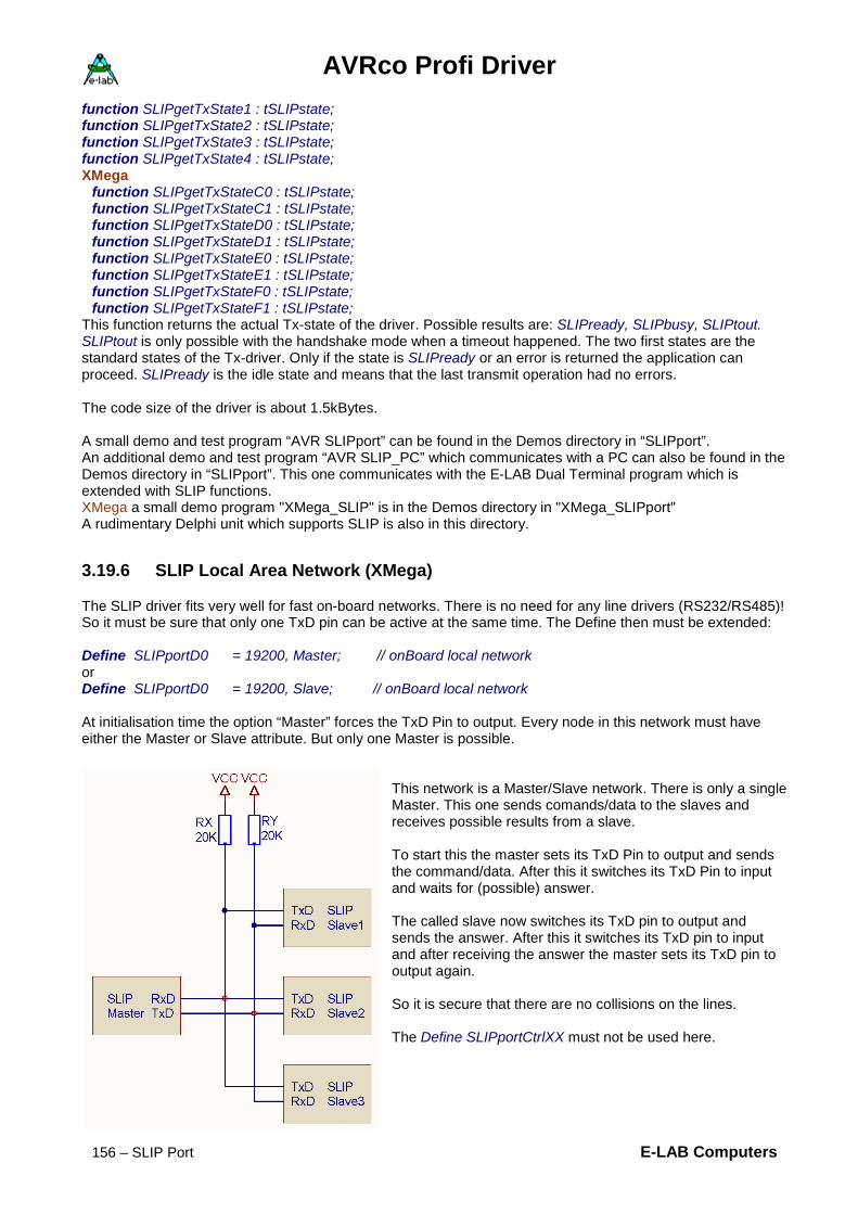
AVRco Profi Driver
156 – SLIP Port E-LAB Computers
function SLIPgetTxState1 : tSLIPstate; function SLIPgetTxState2 : tSLIPstate; function SLIPgetTxState3 : tSLIPstate; function SLIPgetTxState4 : tSLIPstate; XMega
function SLIPgetTxStateC0 : tSLIPstate; function SLIPgetTxStateC1 : tSLIPstate; function SLIPgetTxStateD0 : tSLIPstate; function SLIPgetTxStateD1 : tSLIPstate; function SLIPgetTxStateE0 : tSLIPstate; function SLIPgetTxStateE1 : tSLIPstate; function SLIPgetTxStateF0 : tSLIPstate; function SLIPgetTxStateF1 : tSLIPstate;
This function returns the actual Tx-state of the driver. Possible results are: SLIPready, SLIPbusy, SLIPtout. SLIPtout is only possible with the handshake mode when a timeout happened. The two first states are the standard states of the Tx-driver. Only if the state is SLIPready or an error is returned the application can proceed. SLIPready is the idle state and means that the last transmit operation had no errors. The code size of the driver is about 1.5kBytes. A small demo and test program “AVR SLIPport” can be found in the Demos directory in “SLIPport”. An additional demo and test program “AVR SLIP_PC” which communicates with a PC can also be found in the Demos directory in “SLIPport”. This one communicates with the E-LAB Dual Terminal program which is extended with SLIP functions. XMega a small demo program "XMega_SLIP" is in the Demos directory in "XMega_SLIPport" A rudimentary Delphi unit which supports SLIP is also in this directory.
3.19.6 SLIP Local Area Network (XMega)
The SLIP driver fits very well for fast on-board networks. There is no need for any line drivers (RS232/RS485)! So it must be sure that only one TxD pin can be active at the same time. The Define then must be extended: Define SLIPportD0 = 19200, Master; // onBoard local network or Define SLIPportD0 = 19200, Slave; // onBoard local network At initialisation time the option “Master” forces the TxD Pin to output. Every node in this network must have either the Master or Slave attribute. But only one Master is possible.
This network is a Master/Slave network. There is only a single Master. This one sends comands/data to the slaves and receives possible results from a slave. To start this the master sets its TxD Pin to output and sends the command/data. After this it switches its TxD Pin to input and waits for (possible) answer. The called slave now switches its TxD pin to output and sends the answer. After this it switches its TxD pin to input and after receiving the answer the master sets its TxD pin to output again. So it is secure that there are no collisions on the lines. The Define SLIPportCtrlXX must not be used here.

AVRco Profi Driver
E-LAB Computers SLIP Port - 157
3.19.6.1 Single-Wire Half-Duplex An additional possible way for an on-board SLIP network is to use a a single wire for the communication. This is called a Single-Wire (Half-Duplex) connection. In contrary to the above implementation here every part can be a master or a slave. But be careful, a very good communication architecture must be implemented to avoid collisions! Here is a possible implementation: Define SLIPportC0 = 19200; // onBoard local network SLIPportCtrlC0 = SingleWire; // defines a single-wire or half-duplex connection Electrical implementation:
Attention: The handshake mode is still not implemented in this mode!
TxD
RxD
TxD
RxD
TxD
RxD
TxD
RxD
SLIP1 SLIP2
SLIP3 SLIP4

AVRco Profi Driver
158 – MIRF Driver E-LAB Computers
3.20 MIRF driver Controlling sensors, actuators and with common data transfers often there is the problem of too long cables, electrical isolation and ground loops. To avoid these electrical problems an optical connection (optocouple or fiber glas). But this doesn’t solve the problem of long cables. Also Ethernet is not a good solution because its ground potential and mostly restricted because of high costs.
3.20.1 Wireless RF connection
A possible solution is a radio controlled connection as for example WLAN, Bluetooth or ZigBee. But these need a big use of driver code and unnecessary overhead in the controller/CPU. Because the 2.4GHz ISM band is licence free it is widely used for these purposes. Unfortunately this area is occupied by WLANs, Bluetoot, ZigBee, DECT phones, Babyphones and also micro wave oven. ISM stands for Industrial, Scientific, and Medical band. As one can see above, there can be heavy traffic in this area.
3.20.2 Channels/Frequencies of the ISM band 2.4GHz
Above there are the official free channels/frequencies for general purpose. There are some additional difficulties: these 13 WLAN-channels are not really separated from each other, they overlap themselves. Each WLAN-channel has a bandwith of 3 channels. This means for example that channel number 2 reaches into the frequencies of the channels 1 and 3. Without overlaping only the channels 1, 6 and 11 can be used (WLAN std). Some heavy distortion can be expected in channel 9 and 10 by micro wave oven. The used freqencies (2,452 and 2,457 GHz) are near to the "Microwaven-Frequency" at 2,455 GHz. In order to get the best and trouble free connection with many cases it is necessary to watch the ISM band with a Scanner or Spectrum Analyser tot find unused channels. The typical PC tools are not usable for this because they only recognise pure WLANs, but no Bluetooth, ZigBee etc.

AVRco Profi Driver
E-LAB Computers MIRF Driver - 159
3.20.3 MIRF
Medical Industrial Radio Frequency
MIRF denotes the low-level layer of IEEE 802.15.xx, where also WLAN, Zigbee etc. reside with their lower layers. The standard IEEE 802.15.4 denotes a transportation layer for Wireless Personal Area Networks (WPAN). It defines the lowest two layers of the OSI-model, the bit transfers and the MAC layer. Higher protocol layers with functions for routing and an application interface are defined in another standard for RF-nets like ZigBee. Important targets for this protocol are low current consumption for a long live with batteries, cheap hardware, secure transactions, using of the licence free ISM-band and parallel operation with other transmitters on these frequencies, especially WLAN and Bluetooth. Because of these properties the standard IEEE 802.15.4 is very well suited for Wireless Sensor Networks (WSN). End of the 1990’s there was a need of a simple standard for wireless data transmission for devices with low current consumption and low data rates. The already available standards IEEE 802.11 and Bluetooth were too complex and needed to much current so they could not be build with cheap parts. With the definition of IEEE 802.15.4 there were no high data rates but the energy management and the simplicity had the highest priority. Significant for the nodes of an IEEE 802.15.4 networks are the long pauses where a node can stay in power down mode to save battery energy. If it wants to send or receive data it can wake-up in a short time, communicate and then again go to sleep. So battery operated nodes can run from months to years with one battery.
3.20.3.1 Tx-Power The typical Tx-power of a transceiver is about 0dBm (=1mW) and the Rx-sensitivity is better than -90 dBm. IEEE 802.15.4 was defined for parallel operation with WLAN, ZigBee and Bluetooth. Some tests showed some problems in the co-existence of IEEE 802.15.4 with WLAN and Bluetooth. With Bluetooth the used frequency hopping, which shall avoid collisions with WLAN, occupies some channels and produces distortions an collisions. Also WLAN can make some problems by its heavy traffic and usage.

AVRco Profi Driver
160 – MIRF Driver E-LAB Computers
3.20.3.2 Topology
IEEE 802.15.4 knows two types of nodes with different function counts, the Reduced Function Devices (RFD) and the Full Function Devices (FFD). A RFD has only a subset of the standard functions, so it can only communicate with FFDs. RFDs can be sensors or actors in the network which sometimes send or receive data. They don’t have any management functions and mostly are in standby mode. FFDs have all the functions necessary to communicate with RFDs and also with FFDs. One FFD pro network works as a PAN coordinators. It defines the PAN identifier which isolates this network from other IEEE 80.15.4 networks which can be reached by the RF. Furthermore in Slotted Mode it synchronises all nodes. A network can have up to 256 nodes. The standard defines, based on the above node types, three different topologies:
· Star. Ina star all nodes directly communicate with the coordinator. The coordinator in most cases is a powerful device connected to the mains while the other nodes are mainly battery operated
· Peer-to-Peer. In this network there is also a coordinator but the nodes can communicate with each other, as far they are in a reachable distance.
· Cluster Tree. This is a special implementation and is not discussed here. Because the standard doesn’t define a switching layer (Network Layer) functions like routing must be done by higher layers of other protocols which are build around of IEEE 802.15.4. So real mashed networks can be implemented where FFDs work as a repeater and each node can communicate with each other by using some nodes as relay stations.

AVRco Profi Driver
E-LAB Computers MIRF24 Port - 161
3.21 MIRF24port A MIRF driver basically is bound to a concrete hardware/chip. This is the nrf24L01+ from Nordic Semiconductor. It provides a few excellent features which are used by the driver:
• Worldwide 2.4GHz ISM band operation • 250kbps, 1Mbps and 2Mbps on air data rates • Ultra low power operation • 11.3mA TX at 0dBm output power • 13.5mA RX at 2Mbps air data rate • 900nA in power down • 26μA in standby-I • Automatic CRC generation/check • Automatic handshake without CPU intervention • Automatic multiple retries • Automatic packet handling • Auto packet transaction handling • 6 data pipe MultiCeiver™ • GFSK modulation • 250kbps, 1 and 2Mbps air data rate • 1MHz non-overlapping channel spacing at 1Mbps • 2MHz non-overlapping channel spacing at 2Mbps • Programmable output power: 0, -6, -12 or -18dBm • -82dBm sensitivity at 2Mbps • -85dBm sensitivity at 1Mbps • -94dBm sensitivity at 250kbps • 1 to 32 bytes dynamic payload length • Max 10Mbps SPI interface • 3 separate 32 bytes TX and RX FIFOs • 5V tolerant inputs • 4x4mm

AVRco Profi Driver
162 – MIRF24 Port E-LAB Computers
3.21.1 MIRF24 driver
A MIRF driver basically is bound to a concrete hardware/chip. Here this is the nrf24L01+ from Nordic. Its features are essential for a secure and fast operation. Both a Peer-to-Peer and also a Star network can be implemented.
3.21.1.1 Imports As usual with AVRco the driver must be imported. Import SysTick…, MIRF24port, ..; // driver import The SysTick isn’t mandatory for this driver.
3.21.1.2 Defines Define
ProcClock = 16000000; {Hertz} SysTick = 10; {msec} StackSize = $0040, iData; FrameSize = $0040, iData; MIRF24port = SPI_Soft, PortA, 2, 3, 4, 1, 0, 5; // SCK, MOSI, MISO, SS, CE, IRQ // MIRF24port = SPI, PortA, 0, 1, 2; // standard SPI port // SS, CE, IRQ // MIRF24port = MSPI_2, PortA, 0, 1, 2; // MSPI_0..MSPI_3 // SS, CE, IRQ …
The MIRF hardware is controlled by a SPIport. Three types of SPI are possible: 1. Software SPI through a standard IO-port 2. Hardware SPI through the standard SPI of the controller. XMega SPI_C, SPI_D, SPI_E, SPI_F 3. Hardware SPI through SPI-settable UARTs of the controller, if present. Dependent of the SPI type some control lines must be defined. The unit uMIRF24 must be imported. uses uMIRF24;
3.21.1.3 Types The unit uMIRF24 exports some types: tMRFchan = (mrfChan1, mrfChan2, mrfChan3, mrfChan4, mrfChan5, mrfChan6, mrfChan7, mrfChan8, mrfChan9, mrfChan10, mrfChan11, mrfChan12, mrfChan13, mrfChan14); tMRFpwr = (mrfdBm0, mrfdBm6, mrfdBm12, mrfdBm18); enMRFstat = (mrfTX_full, mrfRX_pn0, mrfRX_pn1, mrfRX_pn2, mrfMAX_RT, mrfTX_DS, mrfRX_DR); tMRFstat = Bitset of enMRFstat; tMRFpkt = (mrfPKTnone, mrfPKTdata, mrfPKTbcast); tMRFrfSpeed = (mrfRF250, mrfRF1000, mrfRF2000);
AVRco Profi Driver
E-LAB Computers MIRF24 Port - 163
3.21.1.4 List of the Functions and Procedures The following procedures and functions mainly serve for Initialising of the driver: procedure mrfSetChan(chan : tMRFchan; wr : boolean); procedure mrfSetFreq(freq : word; wr : boolean); procedure mrfSetPower(pwr : tMRFpwr); procedure mrfSetLocalAddr(adr : byte); procedure mrfSetRetryMax(rmax : byte); procedure mrfSetRetryTimeOut(tmo : byte); procedure mrfSetRFspeed(spd : tMRFrfSpeed); function mrfInit : boolean; procedure mrfSetPWRdown;
These functions return actual States, Eventcounts and Errors:
function mrfGetState : tMRFstat; function mrfGetLostPkts : byte; function mrfGetRetryCnt : byte; function mrfGetRxPower : byte;
These functions are the general Work Functions: function mrfGetRxType : tMRFpkt; function mrfTxPacket(adr : byte; srcPtr : pointer; cnt : byte; bc : boolean) : boolean; function mrfRxPacket(destPtr : pointer; TimeOut : byte; var recvd : byte) : tMRFpkt;
Two Demo and Test programs “AVR MIRF24_M” and “AVR MIRF24_S” can be found in the Demos Directory in “MIRF24”.

AVRco Profi Driver
164 – MIRF24 Port E-LAB Computers
3.21.1.5 Functions and Procedures The following procedures and functions mainly serve for Initialising of the driver. Before the call of the function mrfInit all RxTx-parameter must be correct initiated by the concerning procedures. procedure mrfSetChan(chan : tMRFchan; wr : boolean); This procedure selects the desired RF channel in the ISM band. The channel chan must be passed with the enumeration tMRFchan (mrfChan1.. mrfChan14). The boolean wr defines whether the channel must be immediately written into the 24L01 or not. Before the first Init the wr must be false. After an Init the channel can be changed at runtime with wr = true without doing a new Init. As an alternative the procedure mrfSetFreq can be used. procedure mrfSetFreq(freq : word; wr : boolean); This procedure selects the desired RF frequency in the ISM band. The freq parameter counts in MHz steps. Valid values are 2400..2484. The boolean wr defines whether the frequency must be immediately written into the 24L01 or not. Before the first Init the wr must be false. After an Init the frequency can be changed at runtime with wr = true without doing a new Init. As an alternative the procedure mrfSetChan can be used. procedure mrfSetPower(pwr : tMRFpwr); This procedure sets the desired RF power. The power must be passed with the enumeration tMRFpwr (mrfdBm0.. mrfdBm18). mrfdBm0 is max. Power and mrfdBm18 is minimal power. procedure mrfSetLocalAddr(adr : byte); This procedure defines the local address (0..255). This is the logical address which other nodes must use to communicate with this node. This address must be unique which means that only one node in this network can have this address. procedure mrfSetRetryMax(rmax : byte); This procedure defines the max. retry count (0..15). If there is an error in a data transfer, e.g. the acknowledge of the receiver is too late or fails then the transmitter repeats the telegram up to rmax. If the ACK is still missing the transmit function mrfTxPacket returns with a false. procedure mrfSetRetryTimeOut(tmo : byte); This procedure sets the delay between two retries (1..15). This time is calculated in this way: 250usec + (tmo * 250usec). Typical values should be about 1msec (tmo = 3..4) procedure mrfSetRFspeed(spd : tMRFrfSpeed); This procedure defines the “on air“ data rate. The rate must be given with the enumeration tMRFrfSpeed (mrfRF250, mrfRF1000, mrfRF2000). function mrfInit : boolean; This function initialises the 24L01 with the values given above and starts the receiver. If an error occurs a false is returned. procedure mrfSetPWRdown; This procedure switches the controller 24L01 into the Power-down mode. For a restart then the function mrfInit must be used.

AVRco Profi Driver
E-LAB Computers MIRF24 Port - 165
These functions return actual States, Eventcounts and Errors:
function mrfGetState : tMRFstat; This function returns the Status register of the 24L01. tMRFstat = BitSet of enMRFstat. Normally it is not used. The meaning of the bits must be read in the 24L01 datasheet. function mrfGetLostPkts : byte; This function returns the count of failed Tx-packets which were not successful despite of using all retries. Also the internal lost counter in the 24L01 is reset. function mrfGetRetryCnt : byte; After a successful Tx-operation the function returns the used retries. The higher the count is the worse the connection was. function mrfGetRxPower : byte; This function returns in the Bit0 the received field quality. 0 = bad reception, 1 = good reception.
These functions are the general Work Functions: function mrfGetRxType : tMRFpkt; This function returns the receive packet state. tMRFpkt = (mrfPKTnone, mrfPKTdata, mrfPKTbcast) . It serves for polling the reception. function mrfRxPacket(destPtr : pointer; TimeOut : byte; var recvd : byte) : tMRFpkt This function tries to get a packet out of the 24L01. destPtr must point to a RAM data structure with 32bytes size. TimeOut defines the time in msec which should be waited until success or abort. In recvd the real received byte count is returned (max 32). The function result is tMRFpkt = (mrfPKTnone, mrfPKTdata, mrfPKTbcast) . With a timeout a mrfPKTnone is returned. If a standard data packet has been received a mrfPKTdata is returned. And if a Broadcast has been received a mrfPKTbcast is returned. function mrfTxPacket(adr : byte; srcPtr : pointer; cnt : byte; bc : boolean) : boolean; This function tries to transmit a data packet or a broadcast packet. The parameter adr defines the logical address (0..255) of the desired receivers (Node). srcPtr must point to a source in RAM. The parameter cnt defines the count (size) of the packet to send (max 32). The boolean bc defines whether this should be a broadcast or a data packet. With a broadcast the parameter adr is ignored. The result becomes false if any hardware problem occurred (Data or Broadcast). A false is also returned (Data) if the receiver after x Tx-retries did not send any ACK or the ACK got lost. The MIRF24port driver provides two types of data packet transfers:
1. Broadcast. This packet has certain info so that all reachable MIRF24 nodes receive this packet and can interpret it. In this case the hardware ACK is suppressed and also the receiver application must not respond with any packet.
2. Data. This packet is determined for an unique address (node) and will be received only by this node. The receiver (Node) then automatically responds with hardware ACK to the sender and confirms the correct reception. With a CRC error etc. the ACK is suppressed and the sender must do a retry. An ACK from the receiver at this time doesn’t mean that the receiving application has read out the packet from the 24L01. As long as this didn’t happen the receiver doesn’t respond with any ACK for incoming packets. So the send function returns with a timeout after the retry count has been elapsed.
Attention: Before sending a broadcast and after this there should be a pause so all receiver are ready.

AVRco Profi Driver
166 – MIRF24 Port E-LAB Computers
3.21.2 MIRF24 Hardware
3.21.2.1 MIRF24 Adapter for MIRF24 Modul and E-LAB EVA-Boards MIRFadaptor for MIRF24 and MIRF24P
3.21.2.2 MIRF24 Transceiver Module RF Power = 1mW = 0dBm Option MIRF24P = 100mW = 20dBm
MIRF24 Modul + Adaptor

AVRco Profi Driver
E-LAB Computers MIRF86 Port - 167
3.22 MIRF86port
3.22.1 MIRF86 driver
A MIRF driver basically is bound to a concrete hardware/chip. This is the AT8RF231 from Atmel Semiconductor. It provides a few excellent features which are used by the driver:
• Worldwide 2.4GHz ISM band operation • 250kbps, 1Mbps and 2Mbps on air data rates • Ultra low power operation • 14mA TX at +3dBm output power • 12.3mA RX at 2Mbps air data rate • 20nA in power down • 400μA in standby • Automatic CRC generation/check • Automatic handshake without CPU intervention • Automatic multiple retries • Automatic packet handling • Auto packet transaction handling • Automatic AES encryption and decryption • GFSK modulation • 250kbps, 500kbs, 1 and 2Mbps air data rate • 1MHz non-overlapping channel spacing at 1Mbps • 2MHz non-overlapping channel spacing at 2Mbps • Programmable output power: +3 to -17dBm (max 2mW) • -89dBm sensitivity at 2Mbps • -95dBm sensitivity at 1Mbps • -101dBm sensitivity at 250kbps • 1 to 112 bytes dynamic payload length • Max 7Mbps SPI interface • 3.3V operation with 3.3V inputs • 4x4mm
The AT86RF231 ismuch more uptodate and better than the Nordic chip. Twice output power Much higher input sensitivity PayLoad = Packet size upto 112bytes AES decryption

AVRco Profi Driver
168 – MIRF86 Port E-LAB Computers
3.22.2 MIRF86 driver
A MIRF driver basically is bound to a concrete hardware/chip. Here this is the AT86RF231 from Atmel. Its features are essential for a secure and fast operation. Both a Peer-to-Peer and also a Star network can be implemented.
3.22.2.1 Imports As usual with AVRco the driver must be imported. Import SysTick…, MIRF86port, ..; // driver import The SysTick mandatory for this driver.
3.22.2.2 Defines Define
ProcClock = 16000000; {Hertz} SysTick = 10; {msec} StackSize = $0040, iData; FrameSize = $0040, iData; MIRF86port = SPI_Soft, PortA.2, PortA.3, PortA.4, PortA.1, PortA.0, PortA.5; // SCK, MOSI, MISO, SS, CE, IRQ // MIRF86port = SPI, PortA.0, PortA.1, PortA.2; // standard SPI port // SS, CE, IRQ // MIRF86port = MSPI_1, PortA.0, PortA.1, PortA.2; // MSPI_0..MSPI_3 // SS, CE, IRQ
The MIRF hardware is controlled by a SPIport. Three types of SPI are possible: 1. Software SPI through a standard IO-port 2. Hardware SPI through the standard SPI of the controller. XMega SPI_C, SPI_D, SPI_E, SPI_F 3. Hardware SPI through SPI-settable UARTs of the controller, if present. Dependent of the SPI type some control lines must be defined. The unit uMIRF86 must be imported. uses uMIRF86;
3.22.2.3 Types The unit uMIRF86 exports some types: Init tmrf86chan = (mrf86Chan11, mrf86Chan12, mrf86Chan13, mrf86Chan14, mrf86Chan15, mrf86Chan16, mrf86Chan17, mrf86Chan18, mrf86Chan19, mrf86Chan20, mrf86Chan21, mrf86Chan22, mrf86Chan23, mrf86Chan24, mrf86Chan25, mrf86Chan26); This are 16 2.4GHz channels 11..26 bzw. 2.405GHz..2.484GHz tmrf86pwr = (mrf86dBm3P0, mrf86dBm2P8, mrf86dBm2P3, mrf86dBm1P8, mrf86dBm1P3, mrf86dBm0P7, mrf86dBm0, mrf86dBm1, mrf86dBm2, mrf86dBm3, mrf86dBm4, mrf86dBm5mrf86dBm5, mrf86dBm7, mrf86dBm9, mrf86dBm12, mrf86dBm17); Defines the TX-output power. mrf86dBm3P0 = +3dBm, mrf86dBm0 = 0dBm, mrf86dBm17 = -17dBm tmrf86Speed = (mrf86S250, mrf86S500, mrf86S1000, mrf86S2000); Defines the data rate on air. mrf86S250 = 250kbs, mrf86S2000 = 2Mbs

AVRco Profi Driver
E-LAB Computers MIRF86 Port - 169
Transmit tmrf86mode = (mrf86noBC, mrf86BC); Defines BroadCast or noBroadCast mode tmrf86AesMode = (mrf86AesNone, mrf86AesEncrypt, mrf86AesDecrypt); Defines the AES encryption. mrf86AesNone für Tx und Rx, mrf86AesEncrypt für Rx, mrf86AesDecrypt für Tx tmrf86TxState = (mrf86TxSucces, mrf86TxInvalid, mrf86TxAccessFail, mrf86TxNoACK); Is the result of a transmit operation. Receive tmrf86pkt = (mrf86PKTBroadCast, mrf86PKTData, mrf86PKTnone); The result of a Rx operation, mrf86PKTBroadCast = Broadcast Packet, mrf86PKTData = normales Packet tmrf86rxpacketInfo = record PktTyp : tmrf86pkt; TxAddr : Byte; Crypted : Boolean; flen : Byte; // total byte count or length Retries : Byte; // Retrys rxdata : Pointer; // @ mrf86rxfrm PayLoad : Pointer; // @ mrf86rxfrm + header= Payload start PayCnt : Byte; // effective bytes received ed : Byte; // field strength end; This record can optionally used for further analysation of the received packet.
3.22.2.1 Variables One variable is exported by the Unit uMIRF86: var mrf86rxpacketInfo : tmrf86rxpacketInfo; After a successful receive of a packet this record can be used to further make some investigations.
3.22.2.1 List of the Functions and Procedures The following procedures and functions mainly serve for Initialising of the driver: function mrf86Init : boolean; procedure mrf86SetChan(chan : tmrf86chan; wr : boolean); procedure mrf86SetFreq(freq : word; wr : boolean); procedure mrf86SetPower(pwr : tmrf86pwr); procedure mrf86SetPANaddr(adr : byte); // main address procedure mrf86SetLocalAddr(adr : byte); // sub address procedure mrf86SetRetryMax(rmax : byte); procedure mrf86SetSpeed(speed : tmrf86Speed; wr : Boolean); procedure mrf86SetPWRdown; procedure mrf86SetKey(Const K1, K2, K3, K4, K5, K6, K7, K8, K9, K10, K11, K12, K13, K14, K15, K16 :
Byte);
These functions return actual States, Eventcounts and Errors: function mrf86GetLostPkts : word; function mrf86GetRetryCnt : byte; function mrf86GetRandom : byte;
These functions are the general Work Functions:
function mrf86GetRxType : tmrf86pkt;

AVRco Profi Driver
170 – MIRF86 Port E-LAB Computers
function mrf86TxPacket(adr, panID : byte; bc : tmrf86mode; srcPtr : pointer; Cnt : byte; AESMode : tmrf86AesMode) : tmrf86TxState; function mrf86RxPacket(destPtr : pointer; var recvd : byte; AESMode : tmrf86AesMode) : tmrf86pkt; Two Demo and Test programs “AVR MIRF86_M” and “AVR MIRF86_S” can be found in the Demos Directory in “MIRF86”.

AVRco Profi Driver
E-LAB Computers MIRF86 Port - 171
3.22.2.2 Functions and Procedures The following procedures and functions mainly serve for Initialising of the driver. Before the call of the function mrfInit all RxTx-parameter must be correct initiated by the concerning procedures. procedure mrf86SetChan(chan : tmrf86chan; wr : boolean); This procedure selects the desired RF channel in the ISM band. The channel chan must be passed with the enumeration tMRF86chan (mrf86Chan11.. mrfChan26). The boolean wr defines whether the channel must be immediately written into the 86RF231 or not. Before the first Init the wr must be false. After an Init the channel can be changed at runtime with wr = true without doing a new Init. As an alternative the procedure mrf86SetFreq can be used. procedure mrf86SetFreq(freq : word; wr : boolean); This procedure selects the desired RF frequency in the ISM band. The freq parameter counts in MHz steps. Valid values are 2405.. 2484. The boolean wr defines whether the frequency must be immediately written into the 86RF231 or not. Before the first Init the wr must be false. After an Init the frequency can be changed at runtime with wr = true without doing a new Init. As an alternative the procedure mrf86SetChan can be used. procedure mrf86SetPower(pwr : tmrf86pwr); This procedure sets the desired RF power. The power must be passed with the enumeration tMRF86pwr (mrf86dBm3P0.. mrf86dBm17). Mrf86dBm3P0 is max. Power (+3dBm) and mrf86dBm17 is minimal power (-17dBm). procedure mrf86SetPANaddr(adr : byte); // main address This procedure defines the local PAN address (0..254). This is the logical address which other nodes must use to communicate with this PAN. The effective address is combined from the LocalAddr and PANaddr. It is possible that some nodes have the same PAN addresse but have a different LocalAddr. The value of 255 must not be used. procedure mrf86SetLocalAddr(adr : byte); // sub address This procedure defines the local address (0..254). This is the local address which other nodes must use to communicate with this node. The effective address is combined from the LocalAddr and PANaddr. It is possible that some nodes have the same PAN addresse but have a different LocalAddr. The value of 255 must not be used. procedure mrf86SetRetryMax(rmax : byte); This procedure defines the max. retry count (0..15). If there is an error in a data transfer, e.g. the acknowledge of the receiver is too late or fails then the transmitter repeats the telegram up to rmax. If the ACK is still missing the transmit function mrfTxPacket returns with an error. procedure mrfSetRetryTimeOut(tmo : byte); This procedure sets the delay between two retries (1..15). This time is calculated in this way: 250usec + (tmo * 250usec). Typical values should be about 1msec (tmo = 3..4) procedure mrf86SetSpeed(speed : tmrf86Speed; wr : Boolean); This procedure defines the “on air“ data rate. The rate must be given with the enumeration tMRF86rfSpeed (mrf86S250, mrf86S500, mrf86S1000, mrf86S2000). Before the first Init the wr must be false. After an Init the speed can be changed at runtime with wr = true without doing a new Init. function mrf86Init : boolean; This function initialises the 86RF231 with the values given above and starts the receiver. If an error occurs a false is returned. procedure mrf86SetPWRdown; This procedure switches the controller 86RF231 into the Power-down mode. For a restart then the function mrf86Init must be used.
AVRco Profi Driver
172 – MIRF86 Port E-LAB Computers
These functions return actual States, Eventcounts and Errors:
function mrf*6GetLostPkts : word; This function returns the count of failed Tx-packets which were not successful despite of using all retries. Also the internal lost counter is reset. function mrf86GetRetryCnt : byte; After a successful Tx-operation the function returns the used retries for the last transmit action. The higher the count is the worse the connection was. function mrf86GetRandom : byte; This function returns a real random byte.
These functions are the general Work Functions: function mrf86GetRxType : tmrf86pkt; This function returns the receive packet state. tMRF86pkt = mrf86PKTnone, mrf86PKTdata, mrf86PKTBroadCast)) . It serves for polling the reception. function mrf86RxPacket(destPtr : pointer; var recvd : byte; AESMode : tmrf86AesMode) : tmrf86pkt; This function tries to get a packet out of the 86RF231. destPtr must point to a RAM data structure with 112bytes size. In recvd the real received byte count is returned (max 112). AESmode defines the encryption. The decrypting is automatic if mrf86AesDecrypt is set. But it recognises whether the received packet was encryptet or not. The function result is tMRF86pkt = (mrf86PKTnone, mrf86PKTdata, mrf86PKTBroadCast) . With a timeout a mrfPKT86none is returned. If a standard data packet has been received a mrf86PKTdata is returned. And if a Broadcast has been received a mrf86PKTBroadCast is returned. function mrf86TxPacket(adr, panID : byte; bc : tmrf86mode; srcPtr : pointer; Cnt : byte; AESMode : tmrf86AesMode) : tmrf86TxState; This function tries to transmit a data packet or a broadcast packet. The parameter adr defines the logical address (0..254) of the desired receiver (Node). PanID defines the PAN address (0..254) of the desired receiver (Node). srcPtr must point to a source in RAM. The parameter cnt defines the count (size) of the packet to send (max 112). bc tmrf86mode defines a broadcast or a data packet. With a broadcast the parameters adr and panID are ignored. Both standard and also broadcast can be encrypted. The result is returned with the enumeration tmrf86txState: mrf86TxSucces, mrf86TxInvalid, mrf86TxAccessFail, mrf86TxNoACK The MIRF24port driver provides two types of data packet transfers: 1. Broadcast. This packet has certain info so that all reachable MIRF86 nodes receive this packet and can
interpret it. In this case the hardware ACK is suppressed and also the receiver application must not respond with any packet.
2. Data. This packet is determined for an unique address (node) and will be received only by this node. The receiver (Node) then automatically responds with hardware ACK to the sender and confirms the correct reception. With a CRC error etc. the ACK is suppressed and the sender must do a retry. An ACK from the receiver at this time doesn’t mean that the receiving application has read out the packet from the 86RF231. As long as this didn’t happen the receiver doesn’t respond with any ACK for incoming packets. So the send function returns with a timeout after the retry count has been elapsed.
Attention: Before sending a broadcast and after this there should be a pause so all receiver are ready.

AVRco Profi Driver
E-LAB Computers MIRF86 Port - 173
3.22.3 MIRF86 Hardware
3.22.3.1 MIRF86 Adapter for MIRF86 Modul and E-LAB EVA-Boards MIRF adaptor for MIRF86
3.22.3.2 MIRF24 Transceiver Module RF Power = 2mW = 3dBm

AVRco Profi Driver
174 – FAT Bootloader XMega E-LAB Computers
3.23 FAT Bootloader XMega Often it is necessary to update the firmware in a running device. For this purpose there are some possible ways:
· Download of the new firmware through a serial interface · Download of the new firmware through the USB interface · Download of the new firmware through a microSD card. · Less useful are SPI, I2C and other interfaces
Common with all these operations is that a re-programming of the application can be done only within the boot area. With all AVRs this area resides at the end oft he flash and has different sizes, dependent oft he AVR type. This area can never be reprogrammed by the boot itself and so it is permanent. This bootloader must be written once by the use of a programming tool into the boot area. With „booting“ (re-program) of the application a living/running application must jump into the boot and then the boot starts the download. Furthermore it must be secure that a download of a new firmware was successful and was not disturbed. Otherwise it is impossible to reach the boot out of an invalide application. The best way accomplish this is when a RESET always jumps into the boot, so the FUSE BOOTRST must be active while programming the boot. So the boot always gains control after a RESET etc and now can check the current application for validity. In the AVRco system mostly the last byte in the EEprom is used for this. If this is $FF then there is not a valid application and the bootloader must wait for an external download. If the download was successful then the loader writes a $00 into the EEprom and validates the application. Afterwards the loader switches the vector table to 0000 and jumpst o $0000 into the application. If the application itself must start a download so it must write a $FF into the last EEprom location and then excutes a HardwareReset. This results in a internal real RESET in the AVR which then jumps into the boot area. There at first the the EEprom is checked etcetc. Preconditions: The bootloader must be compiled with {$BootApplication} switch. It must be flashed into the AVR with an external programmer. The application (tob e downloaded) itself only must provide the same CPU type and the constant DownLoaderID : word = nnnn; must be defined. This ID is then checked by the bootloader. The application must have a special format for the FAT Bootloader. This must be done with the help of “AVRprog“. The application is loaded as usual and must be packed into a “DLD“ file. If an AES decryption oft he application should be used the AES key must be provided in the the bootloader and also in the AVRprog and must be identical.
In the AVRprog there are two menu items for this: Download file build without AES encryption Download file build with AES encryption. After making the right choice the target location of the file must be defined, local file or SD-card. Attentiomn: only the Flash, EEprom and UserRow can be flashed. Changing Fuses and LockBits is impossible!
If the AES option was selected, the AES key must be given. This key is used to encrypt the file. This key must be the same as this one defined in the bootloader!

AVRco Profi Driver
E-LAB Computers FAT Bootloader XMega - 175
3.23.1 Bootloader Program
The boot program is very short and kept simple fort he User. Mainly it consists of: two Imports and the Define of the SPI interace fort he microSD card por,t the define of the Boot mode, plain or AES and the dem Define of the boot file name xxxx.DLD, where the DLD must not be given. If the AES mode is selected then the AES key must also beb e present. Example: Import FAT_BootX, FlashWrite; From System Import LongWord; ... Uses uFAT_BootX; ... {$IFDEF FAT_bootModeAES} // mandatory structconst for AES !! structconst DecryptKey : tAESarr = ($00, $11, $22, $33, $44, $55, $66, $77, $88, $99, $AA, $BB, $CC, $DD, $EE, $FF); {$ENDIF} … The driver exports two types, one variable and three functions: … type tBootErr = (bootNoErr, bootInvCardType, bootInvBootType, bootReadFail, bootClusterNotfound, bootFalseID, bootFalseCPU, bootAESerr); tAESarr = Array[0..15] of byte; VAR BootErr : tBootErr; // Initialize the MMC and check for a valid FAT16 file system function FATInit : boolean; {$IfDef FAT_bootModeAES} procedure AES_Init(Key : Pointer); // Pointer TO flash Const!!!! {$endif} procedure FAT_Boot_SetUsrProc(p : procedure); // Set the CallBack address // This reads the UpdateFile and flashes it into the application area. function UpdateFirmware(BootID : word) : boolean; A new application download out of the Bootloader starts with FATInit, if AES mode then AES_Init(@DecryptKey) and then UpdateFirmware(LoaderID). The decrypt key must be the same as this one used in AVRprog for ebcryption! The BootID must be the same as this one used in the application. FatInit and UpdateFirmware can return a false. Then the enumeration „BootErr“ can be checked. If the download was successful the function UpdateFirmware never returns into the boot but immediately jumps into the new application. This can be avoided by implementing the CallBack procedure above. The application itself can force a Bootloader start by writing a $FF into the last EEprom location and then executes a HardwareReset, provided the boot was build as a BootApplication and the fuse BootRst is active. SD card Any type of cards can be used, 2GB..32GB, FAT16 or FAT32, any cluster size. Any types and counts of other files can be there. But the DLD file(s) must be placed into the first 2GB. Resourcen The Bootloader including AES firs into a 4kB boot area, provided the Merlin Optimiser is used.
In the folder ..\E-LAB\AVRco\Demos\XMega_FATboot there is a FAT Boot example and two DLD files for XMega256A3U, one with AES, one without.

Notes

AVRco Profi Driver
E-LAB Computers Device Drivers - 177
Notes

Ó1996-2018 E-LAB Computers Grombacherstr. 27 D74906 Bad Rappenau Tel. 07268/9124-0 Fax. 07268/9124-24 Internet: www.e-lab.de e-mail: [email protected]