profibus-dp master module application …nji... · chapter 1 introduction we appreciate that you...
TRANSCRIPT

HITACHI PROGRAMMABLE CONTROLLER
PROFIBUS-DP MASTER MODULEAPPLICATION MANUAL

WARNING
To ensure that the equipment described by this manual. As well as all equipment connected to and used with it, operate satisfactorily and safety, all applicable local and national codes that apply to installing and operating the equipment must be followed. Since codes can vary geographically and can change with time, it is the user’s responsibility to determine which standard and codes apply, and to comply with them.
FAILURE TO COMPLY WITH APPLICABLE CODES AND STANDARDS CAN RESULT IN DAMAGE TO EQUIPMENT AND/OR SERIOUS INJURY TO PERSONNEL. INSTALL EMARGENCY POWER STOP SWITCH, WHICH OPERATES INDEPENDENTLY OF THE PROGRAMMABLE CONTROLLER TO PROTECT THE EQUIPMENT AND/OR PERSONNEL IN CASE OF THE CONTROLLER MALFUNCTION.
Personnel who are to install and operate the equipment should carefully study this manual and any other referred to by it prior to installation and/or operation of the equipment. Hitachi Industrial Equipment Systems Co., Ltd. constantly strives to improve its products, and the equipment and the manual(s) that describe it may be different from those already in your possession.
If you have any questions regarding the installation and operation of the equipment, or if more information is desired, contact your local Authorized Distributor or Hitachi Industrial Equipment Systems Co., Ltd.
IMPORTANT THIS EQUIPMENT GENERATES, USES, AND CAN RADIATE RADIO FREQUENCY ENERGY AND, IF NOT INSTALLED AND USED IN ACCORDANCE WITH THE INSTRUCTION MANUAL, MAY CAUSE INTERFERENCE TO RADIO COMMUNICATIONS. AS TEMPORARILY PERMITTED BY REGULATION, IT HAS NOT BEEN TESTED FOR COMPLIANCE WITH THE LIMITS FOR CLASS A COMPUTING DEVICES PURSUANT TO SUBPART J OF PART 15 OF FCC ROULES, WHICH ARE DESIGNED TO PROVIDE PEASONABLE PROTECTION AGAINST SUCH INTERFERENCE.
OPERATION OF THIS EQUIPMENT IN A RESIDENTIAL AREA IS LIKELY TO CAUSE INTERFERENCE IN WHICH CASE THE USER, AT HIS OWN EXPENSE, WILL BE REQUIRED TO TAKE WHATEVER MEASURES MAY BE REQUIRED TO CORRECT THE INTERFERENCE.

LIMITED WARRANTY AND IMITATION OF LIABILITY
Hitachi Industrial Equipment Systems Co., Ltd. (Hitachi) warrants to the original purchaser that the programmable logic controller (PLC) manufactured by Hitachi is free from defects in material and workmanship under normal use and service. The obligation of Hitachi under this warranty shall be limited to the repair or exchange of any part or parts which may prove defective under normal use and service within eighteen (18) months from the date of manufacture or twelve (12) months from the date of installation by the original purchaser which ever occurs first, such defect to be disclosed to the satisfaction of Hitachi after examination by Hitachi of the allegedly defective part or parts. This warranty in expressly in lieu of all other warranties expressed or implied including the warranties of merchantability and fitness for use and of all other obligations or liabilities and Hitachi neither assumes, nor authorizes any other person to assume for Hitachi, any other liability in connection with the sale of this PLC. This warranty shall not apply to this PLC or any part hereof which has been subject to accident, negligence, alternation, abuse, or misuse. Hitachi makes no warranty whatsoever in respect to accessories or parts not supplied by Hitachi. The term “original purchaser”, as used in this warranty, shall be deemed to mean that person for whom the PLC in originally installed. In no event, whether as a result of breach of contract, warranty, tort (including negligence) or otherwise, shall Hitachi or its suppliers be liable for any special, consequential, incidental or penal damages including but not limited to, loss or profit or revenues, loss of use of the products or any associated equipment, damage to associated equipment, cost of capital, cost of substitute products, facilities, services or replacement power, down time costs, or claims of original purchaser’s customers for such damages. To obtain warranty service, return the product to your distributor, or send it with a description of the problem, proof of purchase, post paid, insured, and in a suitable package to:
Quality Assurance Dept. Hitachi Industrial Equipment Systems Co., Ltd. 46-1 Ooaza-Tomioka Nakajo-machi Kitakanbara-gun, Niigata-ken 959-2608 JAPAN

Copyright 2002 by Hitachi Industrial Equipment Systems Co., Ltd. All Right Reserved – Printed in Japan
The Information and/or drawing set forth in this document and all right in and to inventions disclosed herein and patent which might be granted thereon disclosing or employing and the materials, methods, techniques or apparatus described herein are the exclusive property of Hitachi Industrial Equipment Systems Co., Ltd .
No copies of the information or drawings shall be made without the prior constant of Hitachi Industrial Equipment Systems Co., Ltd.
Hitachi Industrial Equipment Systems Co., Ltd. provides customer assistance in varied technical areas. Since Hitachi does not possess full access to data concerning all of the uses and applications of customer’s products, responsibility is assumed by Hitachi neither for customer product design nor for any infringement of patents or rights of others, which may result from Hitachi assistance.
The specifications and descriptions contained in this manual were accurate at the time they were approved for printing. Since Hitachi Industrial Equipment Systems Co., Ltd. Incorporated constantly strives to improve all its products, we reserve the right to make changes to equipment and/or manual at any time without notice and without incurring any obligation other than as noted in this manual.
Hitachi Industrial Equipment Systems Co., Ltd. assumes no responsibility for errors that may appear in this manual.
As the product works with user program, and Hitachi Industrial Equipment Systems Co., Ltd. cannot test all combination of user program components, it is assumed that a bug or bugs may happen unintentionally. If it is happened: please inform the fact to Hitachi Industrial Equipment Systems Co., Ltd. or its representative. Hitachi will try to find the reason as much as possible and inform the countermeasure when obtained.
Nevertheless Hitachi Industrial Equipment Systems Co., Ltd. intends to make products with enough reliability, the product has possibility to be damaged at any time. Therefore personnel who are to install and operate the equipment have to prepare with the countermeasure such as power off switch can be operated independently of the controller. Otherwise, it can result in damage to equipment and/or serious injury to personnel.

Safety Precautions
Read this manual and related documents thoroughly before installing, operating, performing preventive maintenance or
performing inspection, and be sure to use the unit correctly. Use this product after acquiring adequate knowledge of
the unit, all safety information, and all cautionary information. Also, make sure this manual enters the possession of
the chief person in charge of safety maintenance.
Safety caution items are classified as "Danger" and "Caution" in this document.
DANGER: Cases where if handled incorrectly a dangerous circumstance may be created, resulting in
possible death or severe injury.
CAUTION: Cases where if handled incorrectly a dangerous circumstance may be created, resulting
in possible minor to medium injury to the body, or only mechanical damage.
However, depending on the circumstances, items marked with may result in major
accidents.
In any case, they both contain important information, so please follow them closely.
Icons for prohibited items and required items are shown below:
: Indicates prohibited items (items that may not be performed). For example, when open flames
are prohibited, is shown.
: Indicates required items (items that must be performed). For example, when grounding must
be performed, is shown.
1. About installation
CAUTION
l Use this product in an environment as described in the catalogue and this document.
If this product is used in an environment subject to high temperature, high humidity, excessive dust,
corrosive gases, vibration or shock, it may result in electric shock, fire or malfunction.
l Perform installation according to this manual.
If installation is not performed adequately, it may result in dropping, malfunction or an operational error
in the unit.
l Do not allow foreign objects such as wire chips to enter the unit.
They may become the cause of fire, malfunction or failure.
CAUTION

2. About wiring
REQUIRED
l Always perform grounding (FE terminal).
If grounding is not performed, there is a risk of electric shocks and malfunctions.
CAUTION
l Connect power supply that meets rating.
If a power supply that does not meet rating is connected, fire may be caused.
l The wiring operation should be performed by a qualified personnel.
If wiring is performed incorrectly, it may result in fire, damage, or electric shock.
3. Precautions when using the unit
DANGER
l Do not touch the terminals while the power is on.
There is risk of electric shock.
l Structure the emergency stop circuit, interlock circuit, etc. outside the programmable controller
(hereinafter referred to as PC).
Damage to the equipment or accidents may occur due to failure of the PC.
However, do not interlock the unit to external load via relay drive power supply of the relay output
module.
CAUTION
l When performing program change, forced output, RUN, STOP, etc., while the unit is running, be sure to
verify safety.
Damage to the equipment or accidents may occur due to operation error.
l Supply power according to the power-up order.
Damage to the equipment or accidents may occur due to malfunctions.

4. About preventive maintenance
DANGER
l Do not connect the , of the battery in reverse. Also, do not charge, disassemble, heat, place in
fire, or short circuit the battery.
There is a risk of explosion or fire.
PROHIBITED
l Do not disassemble or modify the unit.
These actions may result in fire or malfunction.
CAUTION
l Turn off the power supply before removing or attaching module/unit.
Electric shock, malfunction or failure may result.

Table of contents
Chapter 1 INTRODUCTION 1-1
1.1 Before Use.................................................................................................................................................. 1- 11.2 Technical features ..................................................................................................................................... 1- 1
Chapter 2 STRUCTURE and SPECIFICATION 2-1 to 2-2
2.1 Structure and Parts name ......................................................................................................................... 2- 12.2 Specification .............................................................................................................................................. 2- 2
Chapter 3 CONFIGURATIONS 3-1 to 3-7
3.1 System configurations ............................................................................................................................. 3- 13.2 Start up ....................................................................................................................................................... 3- 2
Chapter 4 Installation and Wiring 4-1 to 4-4
4.1 Installation of Module .............................................................................................................................. 4- 14.2 Loading the Module ................................................................................................................................. 4- 14.3 Wiring ......................................................................................................................................................... 4- 2
Chapter 5 Normal Operation 5-1
5.1 Start-up Sequence..................................................................................................................................... 5- 15.2 Data exchange ........................................................................................................................................... 5- 15.3 Data format................................................................................................................................................. 5- 1
Chapter 6 Indications 6-1 to 6-8
6.1 LED Indications......................................................................................................................................... 6- 16.2 Link Information Flag Area...................................................................................................................... 6- 4
Chapter 7 Daily and Periodic Inspection 7-1
Chapter 8 Troubleshooting 8-1

Chapter 1 INTRODUCTION
1-1
Chapter 1 INTRODUCTIONWe appreciate that you have selected the EH-150 Profibus Master Module of the Hitachi programmablelogic controller. This application manual describes how to properly operate the EH-150 Profibus Module.Carefully read the manual to familiarize yourself with the procedures respectively of installation , operation,and maintenance and check.
reference documents(1) EH-150 APLLICATION MANUAL ----------- NJI-281*(X)
*The last character of the manual number may be modified when the product is revised.Notes. The contents of this manual may be modified without previous notice.
1.1 Before UseWhen you purchased the EH-150 Profibus Master Module , please check the following matters:
(1) If model name and specifications are correct.
(2) If there is no shipping damage on product (If any, consult the dealer of this module.)
(3) If following parts are in a carton box.
table 1.1 List of Counter Module Parts
NO. Contents Quantity Remark
1 EH-150 Pofibus Master Module 1
2 Protection sheet 1 For the cover of DIP-SW
Attaching to the case
3 Notes to use 1
1.2 Technical features
Class 1 Profibus-DP master
All baud rates from 9.6kbps up to 12Mbps
Can be used with EH-150 CPU (EH-CPU308/316) ROM version 00 (software version 2.08) and later.
Up to 124 slaves
256 words input data and 256 words output data
Fieldbus connector: 9 pin D-sub , female
Uses the LINK area in the EH-150 CPU.

Chapter 2 STRUCTURE and SPECIFICATION
2-1
Chapter 2 STRUCTURE and SPECIFICATION
2.1 Structure and Parts name
Name and function Model EH-RMP
Weight Approx. 130g
Current Approx. 600mA
dimension (mm)
1) Lock button
3) Connector 1
2) LEDs
5) DIP switch
4) Reset switch
6) Termination switch
7) Connector 2
No Name Function Remarks
1) Lock button This is used when removing the module from the base unit. Afterit is installed to the base unit, the fixation can be reinforced usingscrews. In this case, use M4x10 mm screws.
2) LEDs STATUS: the state of the EH-RMPRUN: communication runningERR: error on communication lineRDY: device has no errorTOKEN: lit all the time
3) Connector 1 Connect to PC(configurator) 9pin male D-sub
Be careful, this connectorbecome hot.
4) Reset switch When module is abnormal, module is be reset by pushing this.
Switch No.
4 3Supplementary explanation
(when the CPU is stopped)
OFF OFF CLEAR mode: the output data is cleared.
OFF ON FREEZE mode: the output data is frozen.
ON OFF COPY mode: the output data is copied from the CPU.
5) DIP switch *1
(No. 1,2 not used)
ON ON Not use
6) Termination switch ON: bus termination enabled
OFF: bus termination disabled
7) Connector 2 Connect to field bus 9pin female D-sub
The screw is the terminal forfunctional earth.
Note1: For setting of this switch, remove the module from the rack.
If the setting ends, cover with the protection sheet.
30
100
9 5

Chapter 2 STRUCTURE and SPECIFICATION
2-2
2.2 Specification
ITEM SpecificationPower source Supplied from power Supply ModuleOperating ambient temperature 0 to 55 degreeStorage ambient temperature -10 to 75 degreeOperating ambient humidity No condensation 20 to 90 % RHStorage ambient humidity No condensation 10 to 90 % RHVibration resistance In accordance with JIS C 0911Noise resistance ¡Noise voltage 1500 Vpp Noise pulse with 100 ns, 1µs by using
noise simurator.¡Based on NEMA ICS 3-304 (with the exception of input module)¡Static noise : 3000 V at metal exposed area
Dielectric withstand voltage 250 V DC between External signal terminal and FE terminal
Consumption current 5 V DC 600 mA
Usage environment No corrosive gasses, no excessive dirt
Structure Attaches to an open wall
General
Cooling Natural air cooling
Number of modules 2/CPU (slot 0 – 2 )
Number of slaves Up to 124 slaves
Output data 256 words
Input data 256 words
I/O assignment LINK 1)
Data transfer rate : Max segment length
9.6 kbps : 1200 m
19.2 kbps : 1200 m
45.45 kbps : 1200 m
93.75 kbps : 1200 m
187.5 kbps : 1000 m
500 kbps : 400 m
1500 kbps : 200 m
3 Mbps : 100 m
6 Mbps : 100 m
12 Mbps : 100 m
Function
Self-diagnosis System ROM/RAM check,
watch-dog timer check
GSD file File name : Hms_1004.gsd
This file can either be downloaded from the webpage
http://www.hms.se/fbfiles.htm
or received by contacting HMS Fieldbus AB .
Configurator Please buy the configurator from HMS Fieldbus AB .
Order number: KONF-PDP
1) LINK area(1024 word ) is used. Can not use for internal I/O.

Chapter 3 CONFIGURATIONS
3-1
Chapter 3 CONFIGURATIONS
3.1 System configurations
I/OI/OI/OI/OI/O
EH
-RM
P
EH
-RM
P
CPU
PWR
Two modules per CPU
0 to 2 slot of basic unit only(can’t mount other slot)
I/O
EH
-IOC
P
PWR
I/OI/OI/O
I/O
EH
-IOC
P
PWR
I/OI/OI/O
EH
-IOC
P
PWR
I/OI/OI/O
0 1 2 3 4 5 6 7
Up to 124 DP-Slaves.
EH-IOCP is up to 99 modules.
Up to 124 DP-Slaves.
EH-IOCP is up to 99 modules.
DP Slave DP Slave DP Slave
I/OI/OI/OI/OI/OI/OI/OI/O
EH
-IOC
PWR
I/O
EH
-IOC
PWR
I/OI/OI/O 8 9 10 11 12 13 14 15
Basic unit Extension unit
Basic unit Extension unit
0 1 2 8 9 10 11 12
I/O
Fig. 3.1 Example of system configurations

Chapter 3 CONFIGURATIONS
3-2
3.2 Start up
To operation this module normally, the making a setup which is shown in the following figure is necessary.
3.2.1 DIP switch
The EH-RMP can be configured to run in different modes depending on the users requirements.
The configuration is accomplished by the switch placed on the right side of the EH-RMP.
(1) Clear mode
When the CPU is switched from RUN to STOP position, the EH-RMP outputs the zero data to Profibus.
But the link output area(WL) is not cleared.
Switch Position
1 Don’t care
2 Don’t care
3 OFF(default)
4 OFF(default)
(2) Freeze mode
When the CPU is switched from RUN to STOP position, the EH-RMP freezes the output data with the valuepresent when the switch is performed.
The "SET RESET" and the "FORCED OUT" function from the programming tool for EH-150 PLC are invalid.
Switch Position
1 Don’t care
2 Don’t care
3 ON
4 OFF
Note 1: The configurations will affect the behavior of the output area when theCPU is turned from RUN to STOP.The behavior of the input area are the same in all modes, the entire input area are always copied.Note 2: Don't operate this switch while EH-RMP is working.
(1) Set the DIP switch. Refer to chapter 3.2.1 .
(3) Set the configuration data from the configuration tool. . Refer to chapter 3.2.3 .
(4) Set the LINK parameter data from the Ladder editor. . Refer to chapter 3.2.4 .
(2) Set the termination switch. . Refer to chapter 3.2.2 .
134
OFF
2
134
OFF
2

Chapter 3 CONFIGURATIONS
3-3
(3) Copy mode
When the CPU is switched from RUN to STOP position, the EH-RMP continues to copy the data present in the linkoutput data. This mode is effective when using the EH-150 CPU(EH-CPU308/316) ROM version 02
(software version 2.12) and later.
Switch Position
1 Don’t care
2 Don’t care
3 OFF
4 ON
3.2.2 Termination switch
The start node and the end node in a Profibus-DP network has to be terminated to avoid reflections on the bus line. TheEH-RMP is equipped with a termination switch to accomplish this in an easy way.
If the module is used as the first or last module in a network the termination switch has to be in ON position.
Otherwise the switch has to be in OFF position.
Termination switch Bus termination
ON ENABLED
If the module is the last or first module, the bus termination has tobe set on, or an external termination connector has to be used.
OFF DISABLED
134
OFF
2The clear mode / the freeze modefor LINK area can be set from user.
EH-CPU 308/316 ROM ver. 02

Chapter 3 CONFIGURATIONS
3-4
3.2.3 Configuration from configuratorThe configuration of the EH-RMP is accomplished by the configurator colled SyConDP.
For general information about the configurator, please refer to the manual for this configurator.
(1) The entry of the EH-RMP
Click the Master icon , and click left-top corner on “Device” area.
Select the “Profibus-DP Master”, and set the station address.
(2) The entry of the slave device
Click the I/O Slave or Module Slave icon, and click left side on “Device” area.
Select a slave device, and set the station address.
Following figure is the example of selected the EH-IOCP of Modular Slave.
Fig. 3.2 Select Master device
Fig. 3.3 Select Slave device

Chapter 3 CONFIGURATIONS
3-5
(3) Make configuration and parameter data
Double click on the selected device.
And make the configuration data and parameter data.
In the configuration data is set the byte offset address from start address of output link area or input link area.
For the details of the configuration data and the parameter data to the slave equipment, please refer to the
manual of each slave equipment.
Fig. 3.4 and Fig. 3.5 is the example for EH-IOCP.
Fig. 3.4 Configuration data for EH-IOCP
Fig. 3.5 Parameter data for EH-IOCP

Chapter 3 CONFIGURATIONS
3-6
(4) Set the bus parameter
In the menu Set-up/Bus parameter the window shows the actual bus parameters.
Changing the baud rate has the consequence, that all other parameters will be re-calculated,
The Highest Station Address is the highest bus address up to which the master will search for other master.
This should not be set below the master address.
Auto_Clear Mode ON, the DP Master leaves the user data transfer and switches the outputs of all assigned DP-slaves to thefail-safe state.
Fig. 3.6 Bus parameter

Chapter 3 CONFIGURATIONS
3-7
3.2.4 Configuration from Ladder Editor
The EH-150 CPU has two link areas of 1024 words (No.1 LINK and No.2 LINK).
The EH-RMP operates in the EH-150 system as a LINK module. The first EH-RMP in a rack uses No.1 LINK area
and the second EH-RMP uses No.2 LINK area .
For the EH-RMP, specify the output area size of the link ( maximum 256 words).
Top Assign No. is fixed to WL0. (for No.2 LINK is WL1000.)
Last Assign No. is between WL0 and WLFF. (for No.2 LINK is between WL1000 and WL10FF.)
Input area of the link is always fixed from WL200 to WL2FF ( for No.2 LINK is WL1200-WL12FF).
Fig. 3.7 LINK Parameter
NOTE1:All address in the link area are word addresses.All address in the configurator(SyCON DP) are byte addresses.
NOTE2:The EH-150 CPU uses 1024 words for the EH-RMP.But the effective data area is 256 words of input data and 256 words of output data.512 words of the remainder are reserved.
WL0
WL200
WL300
WL3FF
RESERVED
RESERVED
Fig. 3.8 LINK area 1 mapping
Input area
Output area Depending on the above link parameter

Chapter 4 Installation and Wiring
4-1
Chapter 4 Installation and Wiring
4.1 Installation of ModuleEH-RMP can be installed in 0-2 slot on the basic base unit.Install and uninstall the module after turn off the base unit power source.
4.2 Loading the Module
(1)Installing
2 )
1 )
1) Hook the claw at the lower section of themodule to the hole in the base.
2) Press in the upper side of the moduleuntil it clicks.
Note 1: After loading the module, check tomake sure it does not come out.
Note 2: Load the power module at theleftmost side of the base unit.
Note 3: Load the CPU module and I/Ocontroller to the right neighbor of thepower module.
(2)Removing
2 )
1 )3 ) 1) Push in the lock button.
2) With the lock button pushed in, pull the topof the module toward the front.
3) Raise it toward the top and pull it out.
Note: For the power module, pull it out whilepushing down the two lock buttons.

Chapter 4 Installation and Wiring
4-2
4.3 Wiring
For information about installation of the Profibus DP fieldbus, please refer to the document : Installation Guideline for PROFIBUS-DP/FMS from PNO, Order No. 2.112.
Profibus homepage on the Internet: http://www.profibus.com
4.3.1 Profibus portEH-RMP has D-sub 9 pin female connector for Profibus port.Use the connector which suits EH-RMP.
Example of a suitable D-sub connector : Siemens, Order number : 6GK1500-0EA02
Table 4.1 Pin order of Profibus port
Pin number Description
1 Shield
2 Not connected
3 B-Line
4 RTS (TTL)
5 GND Bus
6 +5V Bus
7 Not connected
8 A-Line
9 Not connected
Fig. 4.1 The connector type for the EH-RMP
D-sub 9pin maleconnector

Chapter 4 Installation and Wiring
4-3
4.3.2 Cable parametersThe bus cable is specified in EN 50170 part 8-2 as ”Cable Type A”, and should comply with the parameters in the table below.Cable Type B, which is also described in EN 50170, is outdated and should no longer be used.Example of cable for Profibus DP: Siemens, Order number: 6XV1830-0EH10
Table 4.2 Cable parameters
Parameter Cable type ACharacteristic impedance 135 to 165 Ω at a frequency of 3 to 20 MHzOperating capacity < 30 pF/mLoop resistance <= 110 Ω/kmCore diameter > 0.64 mm *)Core cross-section > 0.34 mm2 *)
*) The cable cross-sections used should be compatible with the mechanical specifications of the bus interface connector.
4.3.3 Maximum length of bus segmentThe cable parameters specified for standard Type A bus cables result in the maximum length of each bus segment for therespective data transfer rate shown in table 4.3 .
Table 4.3 Maximum cable lengths per segment
Data transfer rate (kbit/s) 9.6 19.2 93.75 187.5 500 1500 3000 6000 12000
Max. segment length (m) 1200 1200 1200 1000 400 200 100 100 100
<Notes of wiring>1) Add a ferrite core
Insert a ferrite core with the bus cable. Insert a ferrite core with the input/output shielded wires, and wind the shielded wires by oneturn around the ferrite core.
2) To guarantee correct operation, connect to Functional Earth from screw of D-sub femaleconnector.
Fig. 4.2 Functional Earth

Chapter 4 Installation and Wiring
4-4
4.3.4 Configuration port
EH-RMP has D-sub 9 pin male connector for configuration port.The configuration port on EH-RMP is connected to a PC COM port via an ordinary null modem cable.
Table 4.4 Pin order of configuration port
Pin number Signal Description1 NC Not connected2 RxD Receive Data3 TxD Transmit Data4 DTR Data Terminal Ready5 GND Ground6 NC Not connected7 RTS Request To Send8 CTS Clear To Send9 NC Not connected

Chapter 5 Normal Operation
5-1
Chapter 5 Normal Operation
5.1 Start-up SequenceWhen the power is turned on the EH-RMP will perform an internal hardware check.The STATUS LED will flash Green -> Red -> Green -> Red and then start flashing green with 1Hz until theinitialization sequence is finished, then the STATUS LED should be constantly lit green.If the STATUS LED continues to flash with 1Hz and nothing happens, the reason might be that the slot is notconfigured for a link module in the EH-150 CPU.
5.2 Data exchangeWhen the initialization sequence is finished the data exchange with the slave starts automatically.When the CPU is in RUN mode both the input data and the output data will be copied.When the CPU is in STOP mode, the input data are copied in the same way as during RUN mode, but theoutput data behaves according to the setting of the configuration switch.
5.3 Data format
The data format which the EH-RMP outputs at the Profibus-DP is below.
High Byte
07
Octet 1
Low Byte Octet 2
High Byte Low ByteWL**
0815
Byte 1
07
Octet 1
Byte 2 Octet 2
Valid data Can’t useWL**
0815
Valid data Can’t useWL** +n
Fig. 5.1 1 Byte data format for byte oriented slave module
Fig. 5.2 Word data format
As for the output data on slave , high byte and low byte for word data ( or high word and lowword for long word data ) are swapped, it is dependent on slave type.The factor is Word / Byte oriented, Motorola / Intel format.In this case , make the user program after confirming the output format of the data on the slave.
CAUTION
Profibus-DP
Profibus-DP
Chapter 6 Indications
6-1
Chapter 6 Indications
The EH-RMP can give indications to the user in two different ways. The first way is via the five indications LED at thetop of the module and the second way is via the special internal output of EH-150 CPU, where detailed informationabout the Profibus DP network is available for the PLC programmer.
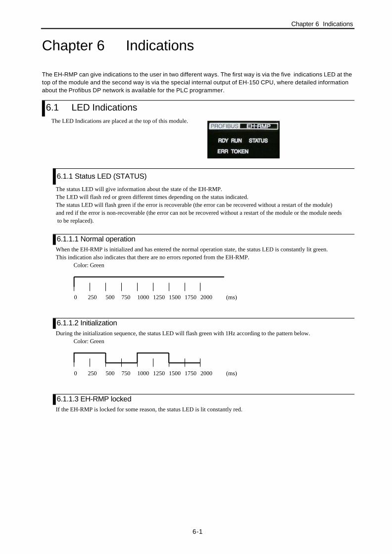
6.1 LED IndicationsThe LED Indications are placed at the top of this module.
6.1.1 Status LED (STATUS)
The status LED will give information about the state of the EH-RMP.The LED will flash red or green different times depending on the status indicated.The status LED will flash green if the error is recoverable (the error can be recovered without a restart of the module)and red if the error is non-recoverable (the error can not be recovered without a restart of the module or the module needs to be replaced).
6.1.1.1 Normal operationWhen the EH-RMP is initialized and has entered the normal operation state, the status LED is constantly lit green.This indication also indicates that there are no errors reported from the EH-RMP.
Color: Green
6.1.1.2 InitializationDuring the initialization sequence, the status LED will flash green with 1Hz according to the pattern below.
Color: Green
6.1.1.3 EH-RMP lockedIf the EH-RMP is locked for some reason, the status LED is lit constantly red.
0 250 500 750 1000 1250 1500 1750 2000 (ms)
0 250 500 750 1000 1250 1500 1750 2000 (ms)

Chapter 6 Indications
6-2
6.1.1.4 Recoverable errorsThe status LED will flash green if the error is recoverable. The flashing sequence are built up according to the figures below.
Color: GreenTwo flashed:
Color: GreenThree flashed:
Color: GreenFour flashes:
Color: GreenFour flashes:
Table 6.1 Recoverable errors
Number offlashes
Fault Cause Action
2 PLC fault If the PLC indicates a fault, the EH-RMPwill stop the data exchange and indicate thisby flashing the status LED two times.
Check the PLC for cause ofthe error.
3 Database download orDatabase not present
When a database is downloaded to theEH-RMP, or if there is no database presentin the EH-RMP, the status LED will flashthree times according to the pattern below.
Database downloading: Wait for the database downloaded to flash.No database present: Download database
4 Link length out ofrange
If the LINK length configured from the PLCis less than 1 or larger than 256 words or ifthe link start address is not equal to zero, thestatus LED will flash green four times.The data exchange will not start.
Check the link length and thelink start address in the PLCprogramming tool.
5 Profibus DP masterfault
If the EH-RMP reports an error during dataexchange, the status LED will flash green fivetimes.
For information about thefault, please check the ‘Errornumber register’, and the‘Device Error register’ in thelink information flag area.
0 250 500 750 1000 1250 1500 1750 2000 (ms)2250 2500 2750 3000
0 250 500 750 1000 1250 1500 1750 2000 (ms)2250 2500 2750 3000 3250 3500 3750 4000
0 250 500 750 1000 1250 1500 1750 2000 (ms)2250 2500 2750 3000 3250 3500 3750 4000
0 250 500 750 1000 1250 1500 1750 2000 (ms)2250 2500 2750 3000 3250 3500 3750 4000

Chapter 6 Indications
6-3
6.1.1.5 Non-Recoverable errorsThe status LED will flash red if the error is non-recoverable. The flashing sequence are built up according to the same patternas for the recoverable errors.
Table 6.2 Non-recoverable errors
Number offlashes
Fault Cause Action
1 RAM fault The RAM check on the EH-RMP carrierboard failed.
Contact supplier
2 FLASH fault The CRC check on the EH-RMP carrierboard failed.
Contact supplier
3 ASIC fault The ASIC check on the EH-RMP carrierboard failed.
Contact supplier
4 Wrong master Wrong master module is mounted on thecarrier board.
Contact supplier
5 Initialization error An error is reported during the initializationof the Profibus DP master.
Check the ‘Error numberregister’, the ‘Error remoteaddress register’ and the‘Device Error register’ in thelink information flag area.
6.1.2 Run LED (RUN)
Color: GreenTable 6.3 Run LED indications
Indication DescriptionCyclically flashing 4Hz (50% on, 50% off) Master is ready to start communicationRandom flashing Configuration error or fatal errorConstantly lit Communication running
6.1.3 Ready LED (RDY)
Color: GreenTable 6.4 RDY LED indications
Indication DescriptionCyclically flashing 4Hz (50% on, 50% off) Hardware or system error or firmware / configuration database
download in progress.Cyclically flashing 1Hz (50% on, 50% off) Flash only contains bootloader, no valid firmware stored in flash.Constantly lit Module is OK. ("Device error = 0")
6.1.4 Error LED (ERR)
Color: RedTable 6.5 ERR LED indications
Indication DescriptionConstantly lit red Error on communication line. If a slave that is configured in the
master is not connected to the fieldbus, this led is lit.Turned off No error
6.1.5 Token LED (TOKEN)
Color: GreenTable 6.6 TOKEN LED indications
Indication DescriptionConstantly lit The master has the token in a multi-master system. If only one
master is used, this LED is lit all the time.Turned off The master does not have the token.
Note: The EH-RMP supports a mono-master system. This LED is lit constantly.

Chapter 6 Indications
6-4
6.2 Link Information Flag AreaIn the Link information flag area, the LADDER EDITOR can get valuable information about the Profibus DP fieldbus.The data is represented in Motorola format in the EH-150 CPU.
Table 6.7 Contents in the LINK information flag area
15 14 13 12 11 10 9 8 7 6 5 4 3 2 1 0Reserved Error Code +00
Reserved +01Reserved +02Reserved +03
Main state of master system Global error bits +04Error number Error remote address +05
Heavy bus error count +06Number of rejected Profibus telegrams +07
Reserved +08Reserved +09Reserved +0AReserved +0B
15 0 +0C31 16 +0D47 32 +0E63 Slave Config 48 +0F79 64 +1095 80 +11111 126 96 +12
- 125 124 123 112 +1315 0 +1431 16 +1547 32 +1663 Slave State 48 +1779 64 +1895 80 +19111 126 96 +1A
- 125 124 123 112 +1BReserved +1CReserved +1DReserved +1EReserved +1FReserved +20Reserved +21Reserved +22Reserved +23Reserved +24Reserved +25Reserved +26
Device Error Reserved +27
Reserved
Refreshing time max (ms) +5DRefreshing time min (ms) +5ERefreshing time now (ms) +5F
OFFSET address(word) Start address of LINK No.1 : WRF0E0 Start address of LINK No.2 : WRF140

Chapter 6 Indications
6-5
6.2.1 Error Code
Table 6.8 Error code
Link module Link address NotesLink No. 1 WRF0E0 Low byte (High byte not used)Link No. 2 WRF140 Low byte (High byte not used)
The following error codes can be present in this register:hex00 No errorhex01 Failed to initialize Profibus DP master.hex02 Start Address of link area in the PLC is not zero.hex03 The link length configured in the PLC equals zero or is larger than 256 words.hex06 Internal Error on Profibus DP master.
6.2.2 Main state of master system
Table 6.9 Main state of master system
Link module Link address NotesLink No. 1 WRF0E4 High byteLink No. 2 WRF144 High byte
This register contains information about the state of the master system. The following states can be present.hex00 Off-linehex40 Stoppedhex80 ClearhexC0 Operate
6.2.3 Global error bits
Table 6.10 Global error bits
Link module Link address NotesLink No. 1 WRF0E4 low byteLink No. 2 WRF144 low byte
The following errors can be present:
Table 6.11 Detail of Global error bits
Bit number Name Description7-6 Reserved5 1= HOST is not ready
0= normal operation4 1= Bus short circuits detected
0= Normal operation3 1= Because of heavy bus error, no further bus communication is possible
0= Normal Operation2 No data 1 = At least one remote node is not in the data exchange mode or reports fatal
error0 = Normal Operation
1 Auto clear 1 = The master branched into auto clear mode because of a remote node error0 = Normal Operation
0 Control 1 = A parameter error occurred0 = Normal Operation

Chapter 6 Indications
6-6
6.2.4 Error number
Table 6.12 Error number
Link module Link address NotesLink No. 1 WRF0E5 High byteLink No. 2 WRF145 High byte
This register can contain two types of errors, Internal errors and External errors, depending on the value of the register ‘Errorremote address’. If ‘Error remote address’ is equal to 0xFF this register reports an Internal error otherwise this registerreports an External error.
6.2.4.1 External errors
Table 6.13 External errors
Value Description Error source Actionhex00 Remote node OK - -hex03 Function in remote node is not activated. Remote node Check if remote node is Profibus DP
norm conform or the correct GSD filesare used.
hex09 No answer data Remote node Check bus cablehex11 No response of the slave Remote node Check bus cable and bus address of the
remote node.hex12 The master is not into the logical token ring. Master Check FDL/node address of master or
highest station address of other mastersystems.
6.2.4.2 Internal errors
Table 6.14 Internal errors
Value Description Error source Actionhex00 No error - -hex32-hex35 Internal error Master Contact supplierhex36 No database present Master Download databasehex37 Faulty parameter value in the master parameter. Project planning Contact supplierhex38 No remote node parameter Project planning Download databasehex39 Faulty parameter value in the remote node parameter. Project planning Contact supplierhex3A Double remote node address Project planning Check remote node addresses.hex3B Projected send process data offset address of a node is
outside the allowable border.Project planning Check projected send offset
addresses.hex3C Projected receive process data offset address of a node
outside the allowable border.Project planning Check projected receive offset
addresses.hex3D Data areas of remote nodes are overlapping in the
receive process area.Project planning Check projected receive offset
addresses.hex3E Data areas of remote nodes are overlapping in the send
process area.Project planning Check projected send offset
addresses.HexCA No segment free Master Contact supplierhexD4 Faulty reading of configuration data Master Download databasehexD5 System fault Master Contact supplierOthers Not allowed - Contact supplier
Chapter 6 Indications
6-7
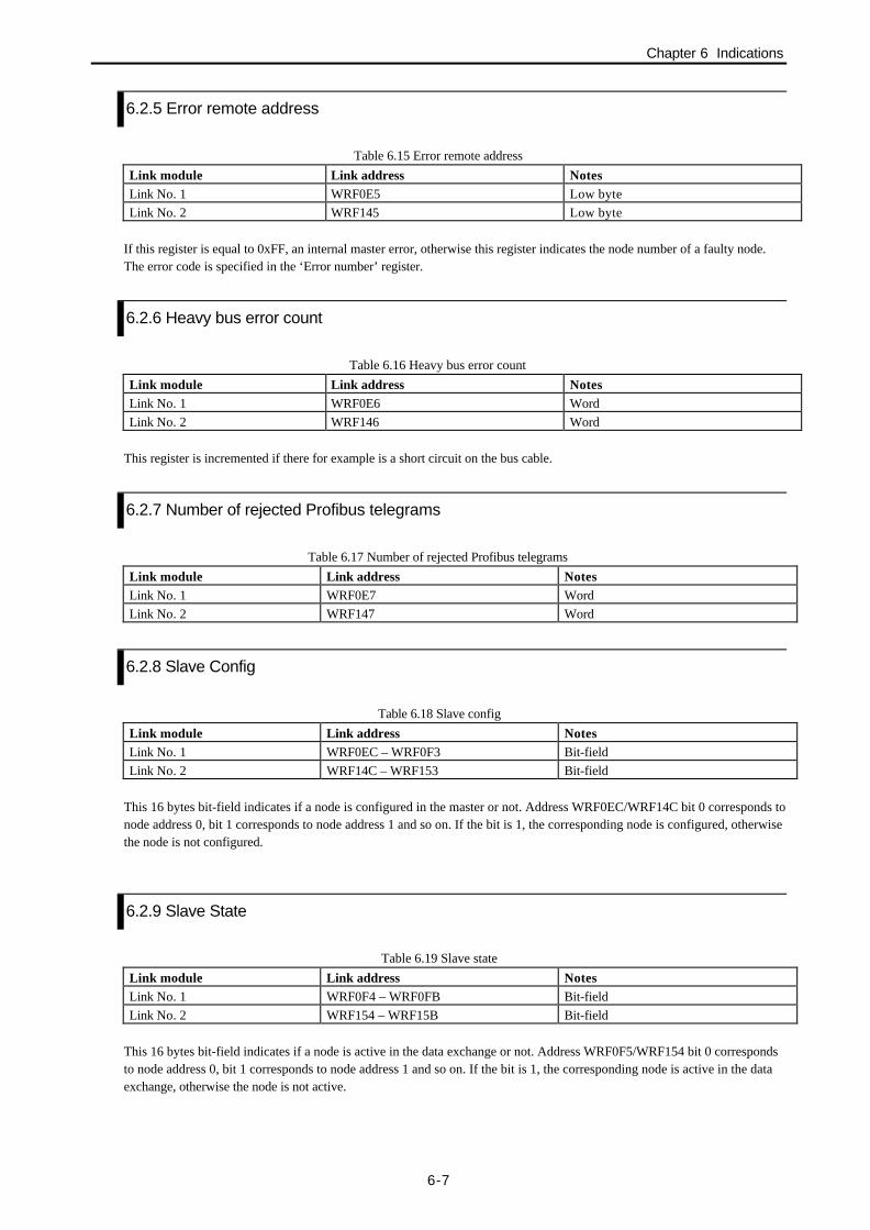
6.2.5 Error remote address
Table 6.15 Error remote address
Link module Link address NotesLink No. 1 WRF0E5 Low byteLink No. 2 WRF145 Low byte
If this register is equal to 0xFF, an internal master error, otherwise this register indicates the node number of a faulty node.The error code is specified in the ‘Error number’ register.
6.2.6 Heavy bus error count
Table 6.16 Heavy bus error count
Link module Link address NotesLink No. 1 WRF0E6 WordLink No. 2 WRF146 Word
This register is incremented if there for example is a short circuit on the bus cable.
6.2.7 Number of rejected Profibus telegrams
Table 6.17 Number of rejected Profibus telegrams
Link module Link address NotesLink No. 1 WRF0E7 WordLink No. 2 WRF147 Word
6.2.8 Slave Config
Table 6.18 Slave config
Link module Link address NotesLink No. 1 WRF0EC – WRF0F3 Bit-fieldLink No. 2 WRF14C – WRF153 Bit-field
This 16 bytes bit-field indicates if a node is configured in the master or not. Address WRF0EC/WRF14C bit 0 corresponds tonode address 0, bit 1 corresponds to node address 1 and so on. If the bit is 1, the corresponding node is configured, otherwisethe node is not configured.
6.2.9 Slave State
Table 6.19 Slave state
Link module Link address NotesLink No. 1 WRF0F4 – WRF0FB Bit-fieldLink No. 2 WRF154 – WRF15B Bit-field
This 16 bytes bit-field indicates if a node is active in the data exchange or not. Address WRF0F5/WRF154 bit 0 correspondsto node address 0, bit 1 corresponds to node address 1 and so on. If the bit is 1, the corresponding node is active in the dataexchange, otherwise the node is not active.

Chapter 6 Indications
6-8
6.2.10 Device error
Table 6.20 Device error
Link module Link address NotesLink No. 1 WRF107 High byte (Low byte not used)Link No. 2 WRF167 High byte (Low byte not used)
Indicates internal faults in the Profibus DP master according to the table below.
Table 6.21 Detail of device error
Value Name Descriptionhex00 - No errorhex0E - OS module, Firmware downloadhex32 RAM_TEST RAM check did not passhex35 FLASH_TEST FLASH PROM checksum not okhex64 - hex6B SYSTEM Internal system errorhexC8 Unknown_IRQ Unknown interrupt received, e.g. through system crashhexC9 Watchdog Internal watchdog expiredhexCA TX_IRQ Unexpected transmit interrupt from serial channelhexCB RX_IRQ Unexpected receive interrupt from serial channelhexFC Download active Firmware Download or Database Download activehexFD Bootloader active Bootstrap loader active, firmware not running

Chapter 7 Daily and Periodic Inspection
7-1
Chapter 7 Daily and Periodic InspectionIn order to use the EH-RMP functions in the most desirable condition and maintain the system to operatenormally, it is essential to conduct daily and periodic inspections.
(1) Daily inspectionVerify the following items while the system is running.
Table 7.1 Items for daily inspection
Item LEDdisplay
Inspectionmethod
Normal status Main cause of error
EH-RMP indication STATUS Visualcheck
Lit Green When unlit: Power supply error or
Hardware error of EH-RMP.
When lit Red: Hardware error of EH-RMP
When flashing Green: Wrong setting value.
When flashing Red: Hardware error of EH-RMP
RDY Visualcheck
Lit Green When unlit: Power supply error or
Hardware error of EH-RMP.When flashing: Hardware or system error
RUN Visualcheck
Lit Green or
Flashing 4Hz
When unlit: Power supply error or
Hardware error of EH-RMP.
When random flashing: configuration error orfatal
Error
ERR Visualcheck
Unlit When lit Red: error on communication line
TOKEN Visualcheck
Lit Green When unlit: Power supply error or
Hardware error of EH-RMP
(2) Periodic inspectionTurn off the power for the external I/O ladder and check the following items once every six months.
Table 7.2 Items for periodic inspection
Part Item Check criteria Remarks
Programming device toCPU
Check operation ofprogramming device
All switches and display lampswork normally.
Power supply Check for voltagefluctuations
85 to 264 V AC (when EH-PSA)
21.6 to 26.4 V DC(when EH-PSD)
Tester
Installation andconnecting areas
(1) All modules aresecurely fixed
(2) All connectors fit snugly
(3) All screws are tight
(4) All cables are normal
No defects Tighten
Check insertion
Tighten
Visual check
Ambient environment (1) Temperature
(2) Humidity
(3) Other
0 to 55 °C20 to 90 % RH (no condensation)
No dust, foreign matter, vibration
Visual check
Spare parts Check number of parts,storage condition
No defects Visual check
Program Check program contents Compare the contents of thelatest program saved and CPUcontents, and make sure theyare the same
Check both master andbackup.

Chapter 8 Troubleshooting
8-1
Chapter 8 TroubleshootingTrouble Possible cause ActionThe ERR LED is lit even if thecommunication seems to work fine.
All nodes that are configured in themaster are not present on the network.
Connect all nodes to make the ERROR LEDturn off. Communication is running on nodesthat are present in the network even if theERROR LED is lit.
A slave does not get on-line even if theslave is configured in the master.
Node address in configurator does notmatch the actual node address.
Check the node address on the slave.
A slave does not react on a commandfrom the PLC even if everything isconfigured correctly.
Wrong offset address is used in the PLCprogram for the specific slave.
Check the input and output offset addressesin the configurator to make sure that the rightaddress is used.