proficy* hmi/scada - ifix · ifix, prior to ifix 5.0. physical node the physical node (also called...
TRANSCRIPT

Proficy* HMI/SCADA - iFIX
L A N R E D U N D A N C Y
V e r s i o n 5 . 5
F e b r u a r y 2 0 1 2

All rights reserved. No part of this publication may be reproduced in any form or by any electronic or mechanical means, including photocopying and recording, without permission in writing from GE Intelligent Platforms, Inc.
Disclaimer of Warranties and Liability
The information contained in this manual is believed to be accurate and reliable. However, GE Intelligent Platforms, Inc. assumes no responsibilities for any errors, omissions or inaccuracies whatsoever. Without limiting the foregoing, GE Intelligent Platforms, Inc. disclaims any and all warranties, expressed or implied, including the warranty of merchantability and fitness for a particular purpose, with respect to the information contained in this manual and the equipment or software described herein. The entire risk as to the quality and performance of such information, equipment and software, is upon the buyer or user. GE Intelligent Platforms, Inc. shall not be liable for any damages, including special or consequential damages, arising out of the user of such information, equipment and software, even if GE Intelligent Platforms, Inc. has been advised in advance of the possibility of such damages. The user of the information contained in the manual and the software described herein is subject to the GE Intelligent Platforms, Inc. standard license agreement, which must be executed by the buyer or user before the use of such information, equipment or software.
Notice
©2012 GE Intelligent Platforms, Inc. All rights reserved. *Trademark of GE Intelligent Platforms, Inc.
Microsoft® is a registered trademark of Microsoft Corporation, in the United States and/or other countries.
All other brands or names are property of their respective holders.
We want to hear from you. If you have comments, questions, or suggestions about our documentation, send them to the following email address:

iii
Table of Contents
About This Guide ............................................................................................................................. 1
Terms for Working with LAN Redundancy ................................................................................... 1
What is LAN Redundancy? .......................................................................................................... 2
Understanding LAN Redundancy ................................................................................................ 3
Alarm Handling for LAN Redundancy ...................................................................................... 4
Limitations of LAN Redundancy ............................................................................................... 4
Configuration Examples: LAN Redundancy ............................................................................. 4
Configuring LAN Redundancy...................................................................................................... 6
Checklist for LAN Redundancy Configuration .......................................................................... 6
Configuring Computers for LAN Redundancy .......................................................................... 7
Enable TCP/IP Networking in the SCU .................................................................................... 7
Enabling LAN Redundancy ...................................................................................................... 9
Updating the HOSTS File for LAN Redundancy .................................................................... 10
Assigning Failover Security Privileges to Users ..................................................................... 11
Configuring Redundant LANs and Non-Redundant PCs ....................................................... 13
Recommendations for LAN Redundancy ............................................................................... 13
Troubleshooting LAN Redundancy ............................................................................................ 15
Log Files for LAN Redundancy .............................................................................................. 15
Using NetDiag to View Connection Statuses ......................................................................... 16
Frequently Asked Questions about LAN Redundancy .......................................................... 16

LAN Redundancy
iv
Examples of LAN Redundancy Used with Enhanced Failover .................................................. 17
Redundant Local Area Network (2 LANs) and One Dedicated LAN ...................................... 18
Redundant Local Area Network (2 LANs) and No Dedicated SCADA Network .................... 30

1
About This Guide The LAN Redundancy e-book is intended for process control engineers, integrators, and developers responsible for designing and creating operator displays, and configuring the development and run-time environments. The manual assumes familiarity with the process database, the iFIX WorkSpace, and the System Configuration Utility (SCU).
This e-book contains the following sections to help you work with the iFIX LAN Redundancy features:
• Terms for Working with LAN Redundancy
• What is LAN Redundancy?
• Understanding LAN Redundancy
• Configuring LAN Redundancy
• Troubleshooting LAN Redundancy
• Examples of LAN Redundancy Used with Enhanced Failover
Terms for Working with LAN Redundancy Before you begin working with LAN Redundancy in iFIX you should familiarize yourself with the following terms:
Term Description
LAN Redundancy LAN Redundancy allows two physical network connections between the iClient and SCADA Server to be used for iFIX networking, providing two redundant, network paths to the same process data. When the connection over one network path is lost, iFIX networking automatically fails over to the other network path.
Active SCADA The fully functioning SCADA node in run mode. The active node sends the process database to standby node. All iClients retrieve their data and alarms from the active SCADA. The active SCADA generates alarms.

LAN Redundancy
2
Term Description
Standby SCADA The "Idle" SCADA·node in run mode. Updates to the standby SCADA are based on database synchronization updates pushed from the active node. The standby node replaces the concept of the backup node in previous versions of iFIX, prior to iFIX 5.0.
Physical Node The physical node (also called the local node) is the local iFIX node name, and should be unique within your iFIX network.
Primary SCADA The first node that you configure in your primary and secondary pair in configure mode for Enhanced Failover. This is the node that goes active when you start iFIX, but may not always be the active node. Enhanced Failover can be used with LAN Redundancy.
Secondary SCADA The second node that you configure in your primary and secondary pair for Enhanced Failover. Enhanced Failover can be used with LAN Redundancy.
iFIX Client node Operators view process data received from a SCADA Server using a client (SCADA or iClient node).
The client obtains data and alarms from the active SCADA node:
A client automatically switches over to the newly active SCADA when a failover occurs.
Any VBA script on the client continues to execute when a failover occurs. If the VBA script is reading data while the failover occurs, the VBA script may return an error.
The Alarm Summary shows the same number of alarm and acknowledge states after a failover occurs. The real-time trend shows some gap in the line chart.
What is LAN Redundancy? LAN Redundancy allows two physical network connections between the iClient and SCADA Server to be used for iFIX networking, providing a backup network path to the same process data. When the connection over one network path is lost, iFIX networking automatically fails over to the other network path.
LAN Redundancy
3
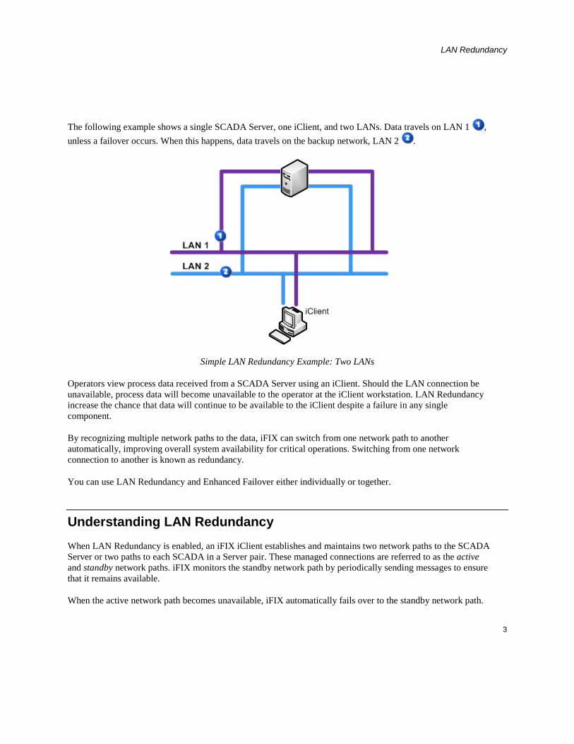
The following example shows a single SCADA Server, one iClient, and two LANs. Data travels on LAN 1 , unless a failover occurs. When this happens, data travels on the backup network, LAN 2 .
Simple LAN Redundancy Example: Two LANs
Operators view process data received from a SCADA Server using an iClient. Should the LAN connection be unavailable, process data will become unavailable to the operator at the iClient workstation. LAN Redundancy increase the chance that data will continue to be available to the iClient despite a failure in any single component.
By recognizing multiple network paths to the data, iFIX can switch from one network path to another automatically, improving overall system availability for critical operations. Switching from one network connection to another is known as redundancy.
You can use LAN Redundancy and Enhanced Failover either individually or together.
Understanding LAN Redundancy When LAN Redundancy is enabled, an iFIX iClient establishes and maintains two network paths to the SCADA Server or two paths to each SCADA in a Server pair. These managed connections are referred to as the active and standby network paths. iFIX monitors the standby network path by periodically sending messages to ensure that it remains available.
When the active network path becomes unavailable, iFIX automatically fails over to the standby network path.

LAN Redundancy
4
You can add links to your pictures to monitor the availability of the standby path. For more information, refer to the Network Status Server Fields section.
Multiple LAN support is always enabled when you have more than one available network path. This means that if you have several available and enabled network paths and LAN Redundancy is not enabled, iFIX attempts to connect to all available paths and keeps the first successful connection. Any other successful connections are closed.
LAN Redundancy, like Enhanced Failover, is not automatically enabled. You must enable LAN Redundancy on all the nodes on which you want to use LAN Redundancy. If LAN Redundancy is enabled, iFIX establishes connections on each of the two paths and manages them both. LAN Redundancy is not supported on any version of FIX (FIX32) for Windows.
LAN Redundancy can be used with or without Enhanced Failover enabled.
Alarm Handling for LAN Redundancy
The Alarm Startup Queue Service is automatically enabled. This service ensures that alarms are not lost during session loss and reconnection, or during failover.
For TCP/IP, the data and alarm sessions will always be over the same LAN because they are using the same socket. If the network connection is lost, then both the data and alarm sessions are re-established over the other LAN connection.
Limitations of LAN Redundancy
When using LAN Redundancy with iFIX, be aware of the following limitations:
• If you also want SCADA Server redundancy, Enhanced Failover must be configured separately. For more information, refer to the Configuring a SCADA Server Pair for Enhanced Failover section.
• For mixed networks (one iClient has a single network card and another iClient has two network cards configured), network names and hosts must be configured properly. For more information, refer to the Configuring Redundant LANs and Non-Redundant PCs section.
• The HOSTS file must be updated manually on each node. If you are using LAN Redundancy with Enhanced Failover, you must update the HOSTS file on the iClient and on each partner SCADA Server. For more information, refer to the Updating the HOSTS File for LAN Redundancy section.
Configuration Examples: LAN Redundancy
The typical LAN Redundancy configuration consists of two network adapter cards in an iClient and two in a SCADA Server. This creates two independent network paths, as illustrated in the following figure.

LAN Redundancy
5
The following figure illustrates an iClient using LAN Redundancy with an excluded card. The SCADA Server has two network cards and an I/O driver Ethernet card that is excluded from LAN Redundancy.

LAN Redundancy
6
Configuring LAN Redundancy This section provides detailed information on configuring LAN Redundancy. It includes the following sections:
• Checklist – LAN Redundancy Configuration
• Configuring Computers for LAN Redundancy
• Enable TCP/IP Networking in the SCU
• Enabling LAN Redundancy
• Updating the HOSTS File for LAN Redundancy
• Assigning Failover Security Privileges to Users
• Configuring Redundant LANs and Non-Redundant PCs
• Recommendations for LAN Redundancy
NOTE: After you perform all the required steps for configuration in the System Configuration Utility (SCU), you will need to save the changes. Restart iFIX on each computer that you configured for the settings to apply.
Checklist for LAN Redundancy Configuration
To ensure that you configured the LAN Redundancy feature properly, use the following checklist. This checklist lists each task in the configuration process, and whether it applies to the primary node, secondary node, and/or iClient. The Secondary SCADA Server column in the following table only applies if the Enhanced Failover feature is configured for use along with LAN Redundancy.
Task Primary SCADA
Secondary SCADA (if
pair is configured)
iClient(s) For more information see...
Ensure your computers meet the minimum hardware requirements.
Hardware Requirements section of the iFIX Getting Started guide.
Configuring Computers for LAN Redundancy

LAN Redundancy
7
Task Primary SCADA
Secondary SCADA (if
pair is configured)
iClient(s) For more information see...
Enable TCP/IP networking in the SCU.
Enable TCP/IP Networking in the SCU
Enable LAN Redundancy in the SCU.
Enabling LAN Redundancy
Update the HOSTS file. Updating the HOSTS File for LAN Redundancy
If security is enabled, assign the Failover security privilege to the appropriate users.
Assigning Failover Security Privileges to Users
If Redundant LANs and Non-Redundant computers are used, update the HOSTS files on the iClients.
Configuring Redundant LANs and Non-Redundant PCs
Configuring Computers for LAN Redundancy
To prepare your iFIX Server and iClient computers for LAN Redundancy, you must obtain the correct hardware. TCP/IP networking and LAN Redundancy must be enabled on all iFIX nodes on your network that you want to use LAN Redundancy.
For a list of supported hardware, refer to the Hardware Requirements section of the iFIX Getting Started guide.
Enable TCP/IP Networking in the SCU
Before you can enable LAN Redundancy in the System Configuration Utility (SCU), you must enable TCP/IP

LAN Redundancy
8
networking in the Network Configuration dialog box in the SCU. You must enable TCP/IP networking on all nodes that use LAN Redundancy. The following figure shows the Network Configuration dialog box with TCP/IP networking enabled.
Network Configuration Dialog Box in the SCU
IMPORTANT: If you use Enhanced Failover with LAN Redundancy, you must perform these steps on the primary computer, the secondary computer, and all iClient computers that connect to the SCADA Server pair. Also, when Enhanced Failover is enabled, the Dynamic Connections check box is cleared by default It is recommended that you leave Dynamic Connections disabled if you are using Enhanced Failover.
To enable TCP/IP networking:
1. On the Start menu, point to Programs, Proficy HMI/SCADA - iFIX, and then System Configuration. The System Configuration Utility (SCU) appears.
2. On the Configure menu, click Network. The Network Configuration dialog box appears.
3. In the Network area, select TCP/IP.

LAN Redundancy
9
4. Click OK.
5. Save the SCU File and close the SCU.
6. Repeat steps 1-5 on each computer you need to update.
Enabling LAN Redundancy
On each computer that uses LAN Redundancy, use the System Configuration Utility (SCU) to enable both network paths and then to select the Enable LAN Redundancy check box. Use the Advanced Network Configuration dialog box in the SCU. To access this dialog box in the Network Configuration dialog box, click the Advanced button. You must enable LAN Redundancy on all nodes that use this feature.
The following figure shows the Advanced Network Configuration dialog box with LAN Redundancy enabled. Two available paths are enabled for LAN Redundancy: Path 1 and 2. Path 0 is disabled because the specified LAN adapter in this example is a dedicated path for SCADA-to-SCADA data synchronization for the Enhanced Failover feature and is not used for iFIX Networking.
LAN Redundancy Portion of the Advanced Network Configuration Dialog Box in the SCU
If you are using LAN Redundancy without Enhanced Failover, you may only have two paths in the Available Paths list, each with LAN Redundancy enabled. For LAN Redundancy, you must have exactly two paths enabled in the Available Paths list.
After you enable LAN Redundancy in the SCU, you must also update the HOSTS file on each computer for

LAN Redundancy
10
LAN Redundancy to work properly.
IMPORTANT: If you use Enhanced Failover with LAN Redundancy, you must perform the following steps on the primary computer, the secondary computer, and all iClient computers that connect to the active SCADA Server pair.
To enable LAN Redundancy:
1. On the Start menu, point to Programs, Proficy HMI/SCADA - iFIX, and then System Configuration. The System Configuration Utility (SCU) appears.
2. On the Configure menu, click Network. The Network Configuration dialog box appears.
3. In the Network area, make sure that the TCP/IP option is selected. If it is not, select it now.
4. Click the Advanced button and click Yes when prompted to continue.
5. For each of the two paths that you want to use for LAN Redundancy, do the following:
a. From the Available Paths list, select the path.
b. In the Status area, select Enable.
6. Select the Enable LAN Redundancy check box. You must have exactly two paths enabled.
7. Click OK. The Advanced Network Configuration dialog box closes.
8. Click OK. The Network Configuration dialog box closes.
IMPORTANT: After you enable LAN Redundancy in the SCU you must add entries for both network paths to the HOSTS file. Without these entries in the HOSTS file, LAN Redundancy will not work properly.
Updating the HOSTS File for LAN Redundancy
After you enable LAN Redundancy in the SCU of each computer, you must edit the HOSTS file on each computer to add entries for each network path. The HOSTS file is typically located in the WINNT\System32\drivers\etc directory. You need to update the HOSTS file on the iClient and SCADA nodes. LAN Redundancy can be used with or without Enhanced Failover enabled.
An entry is needed for each network card. The IP addresses you enter should be static or fixed IP addresses. The names assigned to the second LAN must be the same as the names assigned the first LAN followed by a dash and the letter R (-R). For example, if the network cards on one LAN are STATION1 and PACKER1, the names on the second LAN must be STATION1-R and PACKER1-R, as shown in the following example:
198.212.170.4 STATION1
198.421.103.6 PACKER1
LAN Redundancy
11
1.1.1.2 STATION1-R
1.1.1.5 PACKER1-R
IMPORTANT: All nodes on your iFIX network require a HOSTS file. This includes all iClient nodes, as well as the SCADA nodes. If Enhanced Failover is enabled, the SCADA nodes include both the primary and secondary SCADA nodes. In each HOSTS file, list the names of the SCADA nodes, plus the name -R, as described above. Do not add the iClient nodes to the HOSTS file.
Refer to the Setting Up the Environment manual for more information on TCP/IP and hosts files.
To update the HOSTS file:
1. Open the HOSTS file in a text editor, such as Notepad. The HOSTS file is typically located in the WINNT\System32\drivers\etc directory.
2. Add your entries.
3. Save the file.
4. Repeat steps 1-3 on each computer you need to update.
Assigning Failover Security Privileges to Users
The "Manual Failover" application feature allows you to manually initiate a failover from the active LAN to the standby LAN. "Manual Failover" privileges should be assigned to users or groups who are allowed to manually initiate LAN failover.
The "Manual Failover" feature is listed in the Application Feature Selection dialog box in the Security Configuration application. The following figure shows the Application Feature Selection dialog box with the "Manual Failover" feature added to the Authorized list of application features for the selected user.

LAN Redundancy
12
Security Configuration: Manual Failover Application Feature for User
Refer to the Configuring Security Features manual for more information on configuring iFIX security.
To create an iFIX user with Manual Failover application privileges:
1. Start the Security Configuration application.
2. On the Security toolbox, click the User Account button.
3. Click Add.
4. In the Full Name field, enter a name for the new user account.
5. If using iFIX Security, enter the login name and password for the account in the Login Name and Password fields.
TIP: In iFIX, user names and passwords are not case-sensitive. However, in Proficy Change Management, passwords are case-sensitive. When in iFIX, it is recommended that you enter both the user name and password all in the same case so that it is less likely you will run into issues later.
6. If you want to use Windows security, select the Use Windows Security check box, and, in the Full Name and Domain fields, enter the login name and domain name of the Windows user account you want to use.

LAN Redundancy
13
7. If you want to limit the time the operator remains logged into iFIX, in the Login Timeout field, enter a timeout value.
8. Under the Application security area, click Modify. The Application Feature Selection dialog box appears.
9. In the Available list box, select Manual Failover, and then click Add.
NOTE: To add all the security areas to the current account, click Add All.
10. Click OK.
11. Similarly, modify group accounts and security areas, as required.
12. Click OK.
13. Repeat steps 3-12 for each user you want to add.
14. On the File menu, click Save.
Configuring Redundant LANs and Non-Redundant PCs
If you have a mixed network and LAN Redundancy enabled, for example: one iClient has a single network card and another iClient has two network cards configured, make sure you set up the network names in the HOSTS file properly. The HOSTS file is typically located in the WINNT\System32\drivers\etc directory.
In the HOSTS file, you need an entry for each network card. The names assigned to the second LAN must be the same as the names assigned the first LAN followed by a dash and the letter R (-R). For example, if the network cards on one LAN are STATION1 and PACKER1, the names on the second LAN must be STATION1-R and PACKER1-R, as shown in the following examples.
HOSTS File for Client with 2 Network Cards:
198.212.170.4 STATION1 198.421.103.6 PACKER1 1.1.1.2 STATION1-R 1.1.1.5 PACKER1-R
HOSTS File for Client with a Single Network Card:
198.212.170.4 STATION1 198.421.103.6 PACKER1
Recommendations for LAN Redundancy
To increase efficiency and reduce downtime during LAN failover:

LAN Redundancy
14
• Disable unnecessary network paths
• Balance network timers and failover time
You may want to disable (or exclude) network paths from LAN Redundancy to eliminate the path being used for database synchronization between the SCADA pair, a slow or expensive path, or a path that you want to dedicate to a particular function (such as an I/O driver).
Disabling Network Paths
In addition to enabling LAN Redundancy, you may also want to disable certain network paths that you do not want to use. If you do this, you must ensure that the configurations are the same on both nodes. For example, you may want to disable network path 1 on both nodes.
Re-Enabling Previously Disabled Network Paths
All paths are enabled by default. However, if you have previously disabled a network path, you can re-enable it.
Balancing Network Timers and Failover Time
While multiple LAN support has one managed connection, LAN Redundancy has two managed connections. LAN failover time from the active path to another available path on the same SCADA includes the time required to:
• Detect a connection loss
• Establish or switch low level connections
• Send an iFIX connection establishment message
Because re-establishment of a lost connection occurs over all paths in parallel using the first successful connection, LAN failover after the detection of a lost session takes the normal session establishment time.
With LAN Redundancy enabled, iFIX establishes and maintains two managed connections. Rebroadcast is unnecessary, allowing faster failover to the good connection in the event of connection loss.
The total downtime when using TCP/IP is the greater of the send or receive timer plus the normal session establishment time.
Configuring network session timers reduces the time it takes to detect a connection loss and, consequently, reduces downtime. Refer to the Setting Up the Environment manual for information on customizing network session timers.
CAUTION: Do not change the session timers unless you fully understand how they work and the consequences

LAN Redundancy
15
of what you are doing. If you make the timers too low, you could drop good sessions. If you make them too high, it may take too long to fail over.
Troubleshooting LAN Redundancy Some common troubleshooting issues are outlined in the following table.
Issue Resolution
Nodes are not connecting when configured for LAN Redundancy.
Check the SCU configuration and ensure that both nodes have the same network paths enabled. Refer to the Setting Up the Environment manual for more information.
Check the hosts file and ensure that the name assigned to the second LAN is the same as the name assigned to the first LAN followed by a dash and the letter R (-R). Refer to the Updating the HOSTS File for LAN Redundancy section for more information.
Use the NetDiag utility to view the status of each iFIX network connection. For more information, refer to the Using NetDiag to View Connection Statuses section.
Security does not appear to be configured properly for the LAN Failover security privilege.
For steps on how to check or reconfigure the security areas, refer to the Assigning Failover Security Privileges to Users section.
Log Files for LAN Redundancy
For LAN Redundancy, the error log messages are part of your standard alarm messages. These messages appear in your iFIX Alarm History window. To view the alarm history of the local node, from the system tree in the Proficy iFIX WorkSpace, double-click the Alarm History icon. The following illustrates an example of the Alarm History window.

LAN Redundancy
16
NOTE: The Alarm History window can also be used to monitor Enhanced Failover. A message displays when the active SCADA is switched.
Using NetDiag to View Connection Statuses
iFIX includes a Network Diagnostics program, NETDIAG. This tool is helpful in checking network status with the LAN Redundancy feature. You can also you use this tool for Enhanced Failover to check which SCADA node an iClient, for instance, is communicating with, or whether the primary and secondary nodes are configured properly for iFIX networking.
To start NETDIAG when iFIX is running, click the Start button, point to Run, and then type the following on the command line:
NETDIAG
Use the Active Path and Primary Path fields in the LNT Tbl (logical node name) tab to determine whether the current node is active, and if it is the primary or standby node (1=Yes, 0=No).
The NETDIAG program creates the file, NETDIAG.DAT, in the Application path by selecting the Dump button. This file can be sent to Technical Support Department for further assistance.
For a list of error codes that can appear in NETDIAG, refer to the Startup Error Codes and Run-time Error Codes sections in the Setting up the Environment e-book.
Frequently Asked Questions about LAN Redundancy
The following sections identify questions and answers to commonly asked questions when working with LAN Redundancy.

LAN Redundancy
17
Question Answer
What are the log files available for the LAN Redundancy feature in iFIX?
iFIX Alarm Typers include Alarms to File, Alarm ODBC, Alarm History window for reviewing iFIX error logs for LAN Redundancy.
For more information, refer to the Log Files for Redundancy and Enhanced Failover Features section.
Is there an iFIX security feature for LAN Redundancy?
Yes. For information, refer to the Assigning Failover Security Privileges to Users section.
Examples of LAN Redundancy Used with Enhanced Failover The sections that follow describe examples of the recovery modes for the following configurations:
• Redundant Local Area Network (2 LANs) for Redundant iFIX networking and One Dedicated LAN between the SCADA failover pair as the primary network for data and alarm synchronization, that also uses the iFIX networking networks as the Secondary and Tertiary network for data and alarm synchronization
• Redundant Local Area Network (2 LANs) for iFIX networking and No Dedicated SCADA Network
Both of these recovery mode examples include computers configured with LAN Redundancy and Enhanced Failover.
When reviewing these configurations, be aware of the following terminology:
Term Description
Active Fully functioning SCADA node. Sends synchronization data to standby node. All iClients will get their data and alarms from the active SCADA.
Standby “Idle” SCADA·node. Updates data based on synchronization from the active node.

LAN Redundancy
18
Term Description
Synchronization Database and Alarms. Includes the:
Database (in memory)
SIM / SM2 registers ·
Alarm ODBC ·
Select files – Database, Alarm Area Database (AAD) and I/O drivers Configuration
Switch to Active System message – node switch from Standby to Active· Start SAC block processing (Warm Restart). Allow data and alarm requests. Synchronization data from this node is sent to the standby (if available).
Switch to Standby System message – node switch from Active to Standby · Stop SAC block processing· Reject data and alarm requests· Synchronization waits for data from Active node.
iFIX Client node Obtains data and alarms from the active SCADA node. Automatically switches over to the newly active SCADA when the failover occurs.· VBA script on the client continues to execute when the failover occurs. If the VBA script is reading data while the failover occurs, the VBA script may return an error.·The Alarm Summary shows the same number of alarm and acknowledge states after the failover occurs. The real-time trend shows some gap in the line chart.
Redundant Local Area Network (2 LANs) and One Dedicated LAN
This example shows a Redundant Local Area Network (2 LANs) for Redundant iFIX networking and one dedicated LAN between the SCADA failover pair as the primary network for database synchronization. Also in use are the iFIX networking networks as the Secondary and Tertiary networks for database synchronization
The following scenarios, illustrated in more detail below, describe failure situations that can occur:
• Primary SCADA Unavailable

LAN Redundancy
19
• Secondary SCADA Unavailable
• Both Primary and Secondary SCADA Unavailable
• Primary SCADA Server Connection to LAN1 or LAN2 Failed
• Secondary SCADA Server Connection to LAN1 or LAN2 Failed
• Network to Primary SCADA from the Client Unavailable
• Network to Secondary SCADA from the Client Unavailable
• Dedicated Network Between Primary and Secondary Unavailable
• Complete Network Failure
• Both LAN1 and LAN2 Fails
• Network LAN 1 or LAN 2 Fails
The sections that follow describe the recovery state of the primary SCADA, secondary SCADA, and iClient should one of these scenarios occur.
Scenario 1: Primary SCADA Unavailable
The following example illustrates two local area networks (LANs), with a dedicated network for SCADA synchronization, and a single failure point.
The following table describes the items in the previous figure.

LAN Redundancy
20
Item State
Primary SCADA Server Unavailable.
Secondary SCADA Server Switches to Active. No Synchronization.
iFIX Client The iFIX Client detects loss of communication to the primary node and switches to the newly active node. The iFIX Client generates a system message that communication was lost to the primary SCADA node. The Client obtains data and alarms from the secondary SCADA.
Scenario 2: Secondary SCADA Unavailable
The following example illustrates two local area networks (LANs), with a dedicated network for SCADA synchronization, and a single failure point.
The following table describes the items in the previous figure.

LAN Redundancy
21
Item State
Primary SCADA Server Active. No Synchronization.
Secondary SCADA Server Unavailable.
iFIX Client The iFIX Client detects loss of communication to secondary node. The iFIX Client generates a system message that communication was lost to secondary SCADA node. The Client obtains data and alarms from the primary SCADA.
Scenario 3: Both Primary and Secondary SCADA Unavailable
The following example illustrates two local area networks (LANs), with a dedicated network for SCADA synchronization, and two failure points.
The following table describes the items in the previous figure.

LAN Redundancy
22
Item State
Primary SCADA Server Unavailable.
Secondary SCADA Server Unavailable.
iFIX Client The iFIX Client generates a system message that communication was lost to both the primary and secondary SCADA nodes. The iFIX Client fails to obtain data and alarms.
Scenario 4: Primary SCADA Server Connection to LAN1 or LAN2 Failed
The following example illustrates two local area networks (LANs), with a dedicated network for SCADA synchronization, and a single failure point, in two different scenarios.
The following table describes the items in the previous figure.
LAN Redundancy
23
Item State
Primary SCADA Server Active. Synchronization occurs over dedicated network.
Secondary SCADA Server Standby. Since the active and standby nodes are communicating over the dedicated network, they never switch.
iFIX Client The iFIX Client generates a system message that the connection switched to LAN1 or LAN2. The Client continues to obtain data and alarms from the primary SCADA.
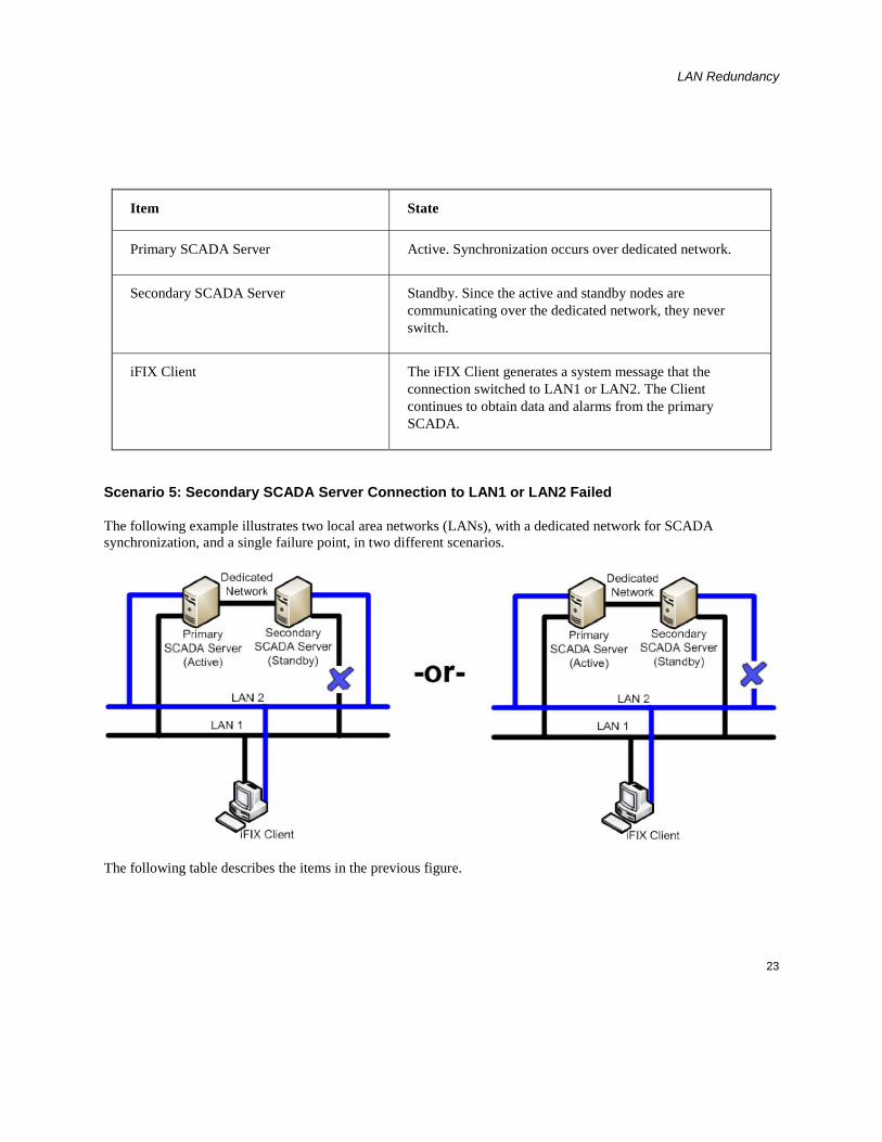
Scenario 5: Secondary SCADA Server Connection to LAN1 or LAN2 Failed
The following example illustrates two local area networks (LANs), with a dedicated network for SCADA synchronization, and a single failure point, in two different scenarios.
The following table describes the items in the previous figure.

LAN Redundancy
24
Item State
Primary SCADA Server Active. Synchronization occurs over dedicated network.
Secondary SCADA Server Standby. Since the active and standby nodes are communicating over the dedicated network, they never switch.
iFIX Client The iFIX Client generates a system message that the connection switched to LAN1 or LAN2. The Client continues to obtain data and alarms from the primary SCADA.
Scenario 6: Network to Primary SCADA from the Client Unavailable
The following example illustrates two local area networks (LANs), with a dedicated network for SCADA synchronization, and two failure points.
The following table describes the items in the previous figure.

LAN Redundancy
25
Item State
Primary SCADA Server Active. Synchronization occurs over dedicated network.
Secondary SCADA Server Standby. Since the active and standby nodes are communicating over the dedicated network, they never switch.
iFIX Client The iFIX Client switches to the standby SCADA and fails to obtain up-to-date data directly from the active SCADA. The iClient reads data through the standby SCADA but will not get new alarms. The iFIX Notification message displays in this situation. Writes from the iClient node are not allowed.
Scenario 7: Network to Secondary SCADA from the Client Unavailable
The following example illustrates two local area networks (LANs), with a dedicated network for SCADA synchronization, and two failure points.
The following table describes the items in the previous figure.

LAN Redundancy
26
Item State
Primary SCADA Server Active. Synchronization occurs over dedicated network, if configured.
Secondary SCADA Server Standby.
iFIX Client The iFIX Client generates a system message that communication was lost to the secondary SCADA node. The Client continues to obtain data and alarms from the primary SCADA.
Scenario 8: Dedicated Network Between Primary and Secondary Unavailable
The following example illustrates two local area networks (LANs), with a dedicated network for SCADA synchronization, and a single failure point.
The following table describes the items in the previous figure.

LAN Redundancy
27
Item State
Primary SCADA Server Active. Synchronization occurs over LAN1 or LAN2.
Secondary SCADA Server Standby.
iFIX Client The Client continues to obtain data and alarms from the primary SCADA.
Scenario 9: Complete Network Failure
The following example illustrates two local area networks (LANs), with a dedicated network for SCADA synchronization, and multiple failure points. In this example, the dedicated network between the primary and secondary SCADA is unavailable. The network from the primary SCADA to the Client is unavailable. The network from the secondary SCADA to the Client is also unavailable.
The following table describes the items in the previous figure.

LAN Redundancy
28
Item State
Primary SCADA Server Active. No Synchronization.
Secondary SCADA Server Switches to Active. No Synchronization.
iFIX Client The iFIX Client generates a system message that communication was lost to both the primary and secondary SCADA nodes. The iFIX Client fails to obtain data and alarms.
Scenario 10: Both LAN1 and LAN2 Fails
The following example illustrates two local area networks (LANs), with a dedicated network for SCADA synchronization, and multiple failure points. The LAN1 and LAN2 networks from the primary SCADA to the Client are unavailable. The LAN1 and LAN2 networks from the secondary SCADA to the Client are also unavailable.
The following table describes the items in the previous figure.
LAN Redundancy
29
Item State
Primary SCADA Server Active. Synchronization occurs over dedicated network.
Secondary SCADA Server Standby.
iFIX Client The iFIX Client generates a system message that communication was lost to both the primary and secondary SCADA nodes. The iFIX Client fails to obtain data and alarms.
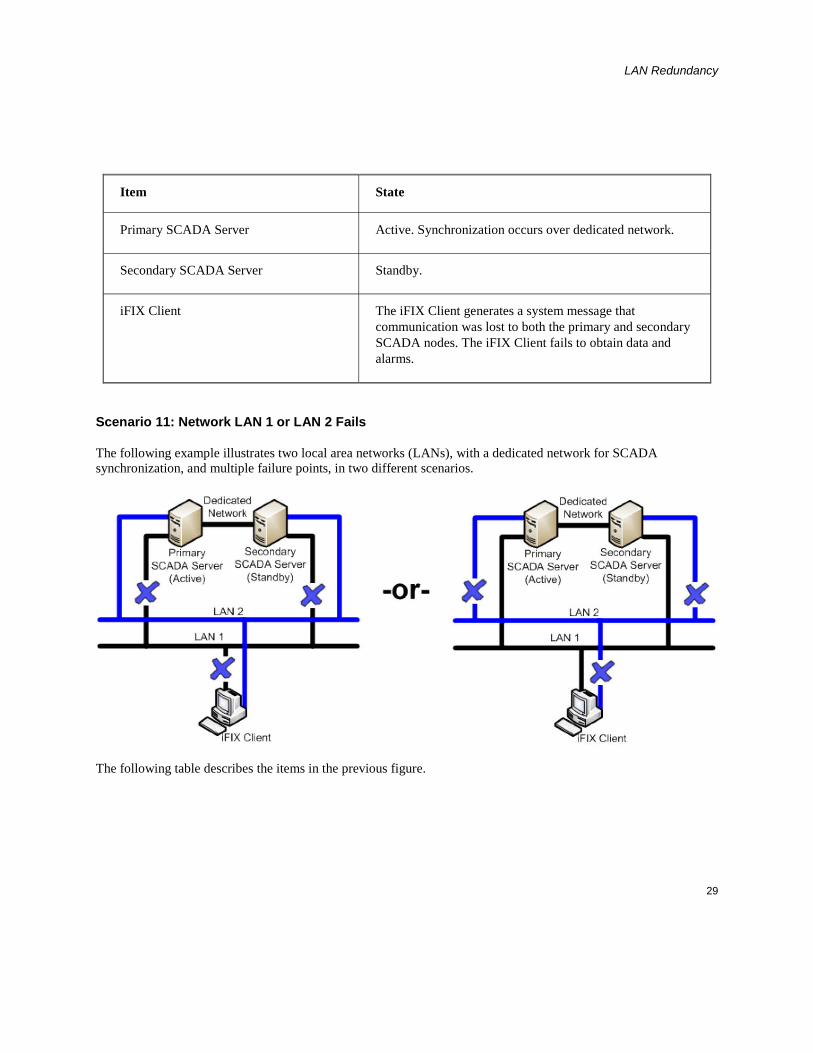
Scenario 11: Network LAN 1 or LAN 2 Fails
The following example illustrates two local area networks (LANs), with a dedicated network for SCADA synchronization, and multiple failure points, in two different scenarios.
The following table describes the items in the previous figure.

LAN Redundancy
30
Item State
Primary SCADA Server Active. Synchronization occurs over dedicated network.
Secondary SCADA Server Standby. Since active and standby nodes are communicating over the dedicated network, they never switch.
iFIX Client The iFIX Client generates a system message that the connection switched to LAN1 or LAN2. The Client obtains data and alarms from the primary SCADA.
Redundant Local Area Network (2 LANs) and No Dedicated SCADA Network
IMPORTANT: This configuration is not supported. The SCADAs using Enhanced Failover should have a dedicated LAN available.
The following scenarios, illustrated in more detail below, describe failure situations that can occur:
• Primary SCADA Unavailable
• Secondary SCADA Unavailable
• Both Primary and Secondary SCADA Unavailable
• Primary SCADA Server Connection to LAN1 or LAN2 Failed
• Secondary SCADA Server Connection to LAN1 or LAN2 Failed
• Network to Primary SCADA from the Client Unavailable
• Network to Secondary SCADA from the Client Unavailable
• Dedicated Network Between Primary and Secondary Unavailable
• Complete Network Failure
• Network LAN1 or LAN2 Failed
The sections that follow describe the recovery state of the primary SCADA, secondary SCADA, and iClient
LAN Redundancy
31
should one of these scenarios occur.
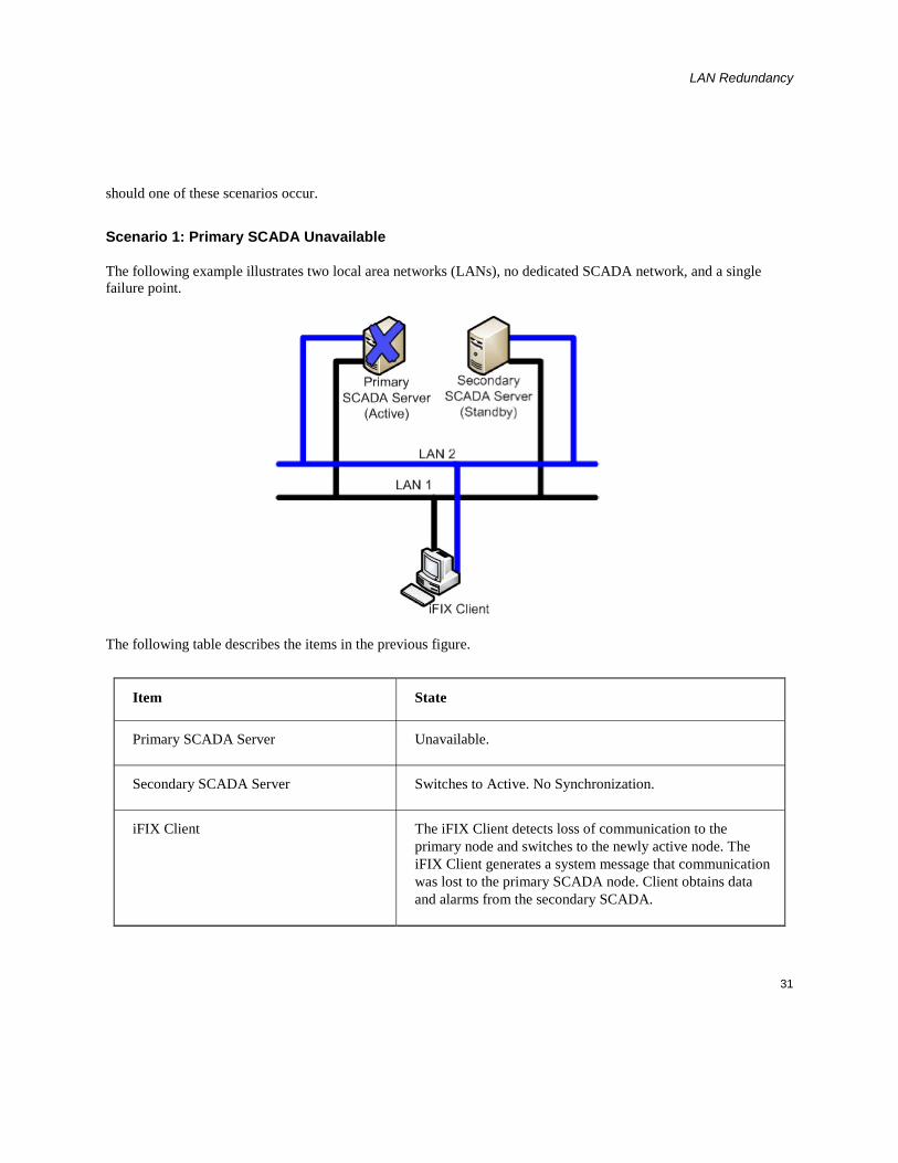
Scenario 1: Primary SCADA Unavailable
The following example illustrates two local area networks (LANs), no dedicated SCADA network, and a single failure point.
The following table describes the items in the previous figure.
Item State
Primary SCADA Server Unavailable.
Secondary SCADA Server Switches to Active. No Synchronization.
iFIX Client The iFIX Client detects loss of communication to the primary node and switches to the newly active node. The iFIX Client generates a system message that communication was lost to the primary SCADA node. Client obtains data and alarms from the secondary SCADA.

LAN Redundancy
32
Scenario 2: Secondary SCADA Unavailable
The following example illustrates two local area networks (LANs), no dedicated SCADA network, and a single failure point.
The following table describes the items in the previous figure.
Item State
Primary SCADA Server Active. No Synchronization.
Secondary SCADA Server Unavailable.
iFIX Client The iFIX Client detects loss of communication to Secondary node. The iFIX Client generates a system message that communication was lost to the secondary SCADA node. Client continues to obtain data and alarms from the primary SCADA.
LAN Redundancy
33
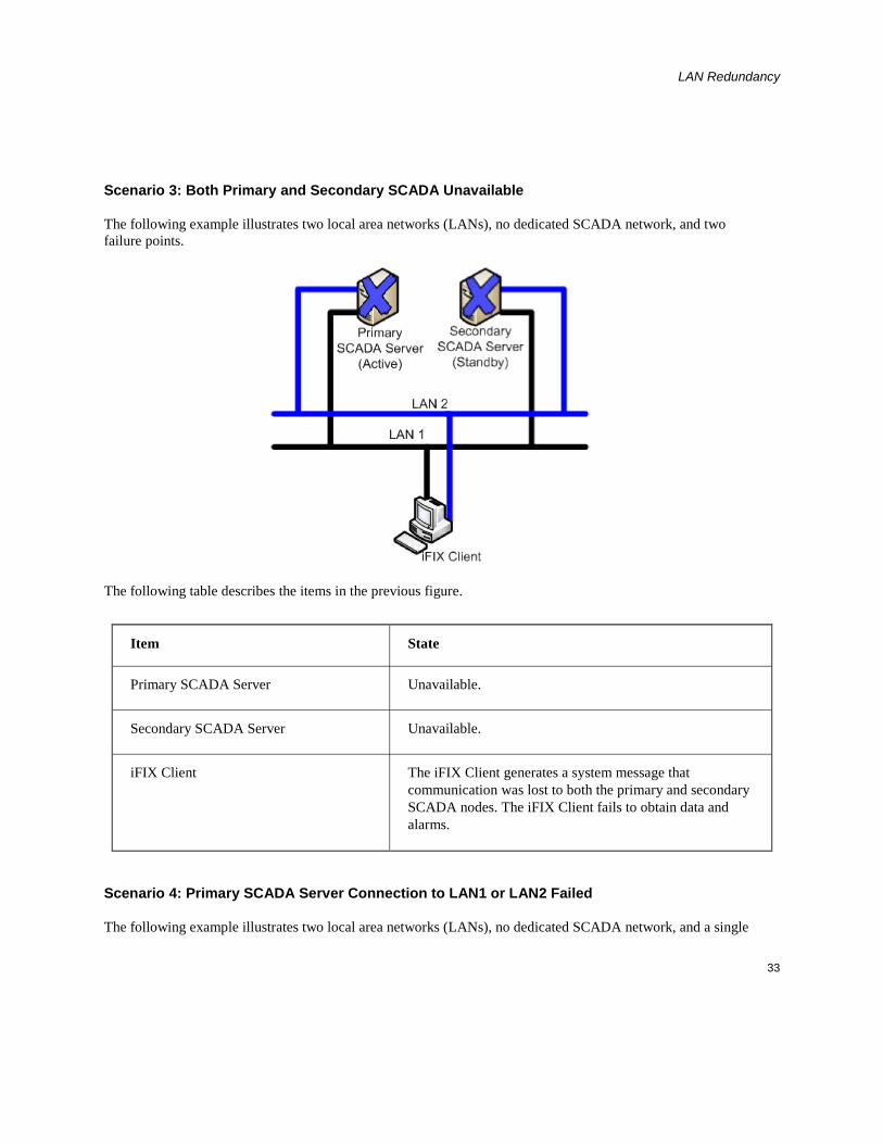
Scenario 3: Both Primary and Secondary SCADA Unavailable
The following example illustrates two local area networks (LANs), no dedicated SCADA network, and two failure points.
The following table describes the items in the previous figure.
Item State
Primary SCADA Server Unavailable.
Secondary SCADA Server Unavailable.
iFIX Client The iFIX Client generates a system message that communication was lost to both the primary and secondary SCADA nodes. The iFIX Client fails to obtain data and alarms.
Scenario 4: Primary SCADA Server Connection to LAN1 or LAN2 Failed
The following example illustrates two local area networks (LANs), no dedicated SCADA network, and a single

LAN Redundancy
34
failure point, in two different scenarios.
The following table describes the items in the previous figure.
Item State
Primary SCADA Server Active. Synchronization occurs over LAN2 or LAN1.
Secondary SCADA Server Standby. Since active and standby nodes are communicating, they never switch.
iFIX Client The iFIX Client generates a system message that connection switched to LAN1 or LAN2. The Client continues to obtain data and alarms from the primary SCADA.
Scenario 5: Secondary SCADA Server Connection to LAN1 or LAN2 Failed
The following example illustrates two local area networks (LANs), no dedicated SCADA network, and a single failure point, in two different scenarios.

LAN Redundancy
35
The following table describes the items in the previous figure.
Item State
Primary SCADA Server Active. Synchronization occurs over LAN2 or LAN1.
Secondary SCADA Server Standby. Since active and standby nodes are communicating, they never switch.
iFIX Client The iFIX Client generates a system message that the connection switched to LAN1 or LAN2. The Client continues to obtain data and alarms from the primary SCADA.
Scenario 6: Network to Primary SCADA from the Client Unavailable
The following example illustrates two local area networks (LANs), no dedicated SCADA network, and two failure points.

LAN Redundancy
36
The following table describes the items in the previous figure.
Item State
Primary SCADA Server Active. No Synchronization.
Secondary SCADA Server Switches to Active. No Synchronization.
iFIX Client The iFIX Client detects loss of communication to the primary node and switches to newly active secondary SCADA node. The iFIX Client generates a system message that communication was lost to primary SCADA node. The Client obtains data and alarms from the secondary SCADA.
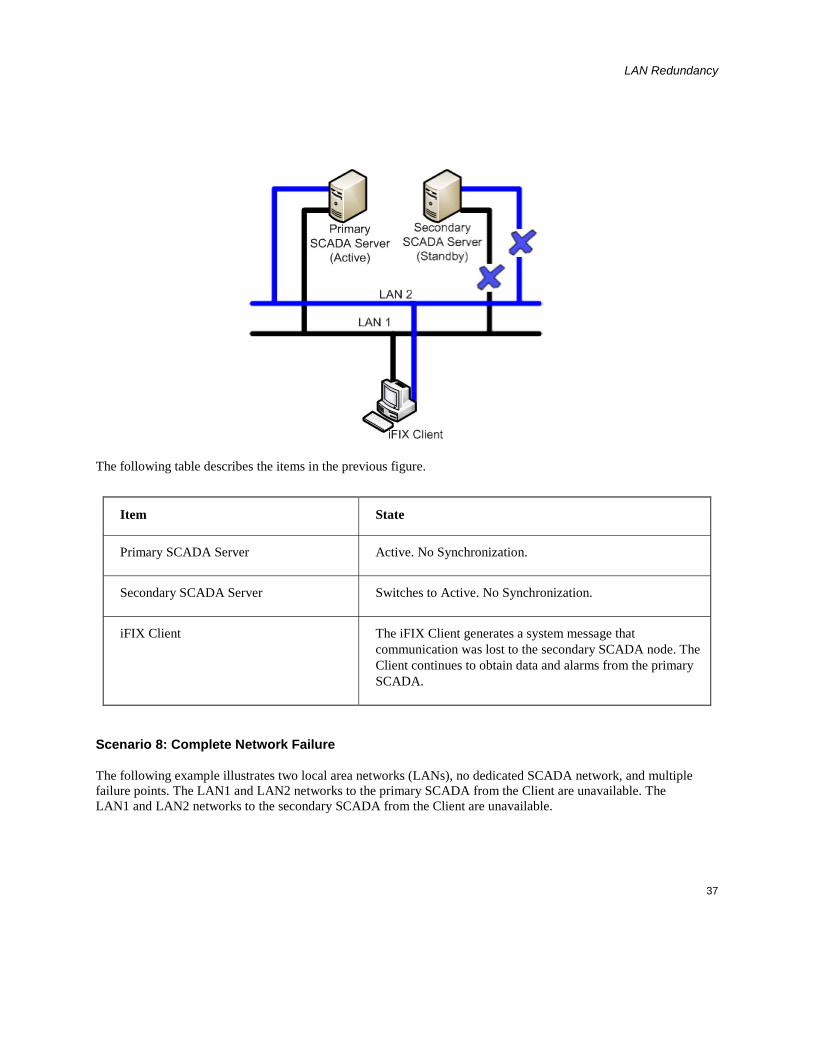
Scenario 7: Network to Secondary SCADA from the Client Unavailable
The following example illustrates two local area networks (LANs), no dedicated SCADA network, and two failure points.
LAN Redundancy
37
The following table describes the items in the previous figure.
Item State
Primary SCADA Server Active. No Synchronization.
Secondary SCADA Server Switches to Active. No Synchronization.
iFIX Client The iFIX Client generates a system message that communication was lost to the secondary SCADA node. The Client continues to obtain data and alarms from the primary SCADA.
Scenario 8: Complete Network Failure
The following example illustrates two local area networks (LANs), no dedicated SCADA network, and multiple failure points. The LAN1 and LAN2 networks to the primary SCADA from the Client are unavailable. The LAN1 and LAN2 networks to the secondary SCADA from the Client are unavailable.

LAN Redundancy
38
The following table describes the items in the previous figure.
Item State
Primary SCADA Server Active. No Synchronization
Secondary SCADA Server Switches to Active. No Synchronization
iFIX Client The iFIX Client generates a system message that communication was lost to both the primary and secondary SCADA nodes. The iFIX Client fails to obtain data and alarms.

LAN Redundancy
39
Scenario 9: Network LAN1 or LAN2 Failed
The following table describes the items in the previous figure.
Item State
Primary SCADA Server Active – Synchronization over LAN2 or LAN1.
Secondary SCADA Server Standby. Since active and standby nodes are communicating, they never switch.
iFIX Client The iFIX Client generates a system message that connection switched to LAN1 or LAN2. The Client continues to obtain data and alarms from the primary SCADA.


1
Index A
application feature ................................................... 12
C
checklist ..................................................................... 6
H
HOSTS file .............................................................. 11
L
LAN Redundancy .......................................... 3, 4, 6, 9
limitations .................................................................. 4
M
Manual Failover ....................................................... 12
Manual Failover application feature ........................ 12
N
NETDIAG ............................................................... 16
Network Diagnostics program ................................. 16
R
Recommendations for LAN Redundancy ................ 14
recovery modes ........................................................ 17
Redundant Local Area Network (2 LANs) and No Dedicated SCADA Network .......................... 30
Redundant Local Area Network (2 LANs) and One Dedicated LAN ............................................ 19
S
socket ......................................................................... 4
T
TCP/IP networking .................................................... 8