proflex control valves - klinger.dk
TRANSCRIPT

PROFLEX Control Valves
Globe Control Valves 3-way Control Valves
Pneumatic Diaphragm Actuators, Type T Pneumatic Diaphragm Actuators, Type S
Pneumatic Screw-in Temperature Controllers Operating Instruction Edition October 2002

Table of content 1 Safety instructions 2 General
2.1 Valve applications 2.2 Design and principles
- Globe control valves - 3-way control valves - Pneumatic diaphragm actuators, type T - Pneumatic diaphragm actuators, type S
2.3 Mounting positions 2.4 Mounting and connections 2.5 Pre loading the springs
3 Pneumatic Diaphragm Actuators 3.1 Separate and assemble valve and actuator
3.2 Change fail-safe position 3.3 Exchange diaphragm 3.4 Electrical actuators
4 Control Valves
4.1 Exchange stem packing 4.2 Exchange stem packing and body gaskets 4.3 Exchange stem and plug 4.4 Reduction of kv-value
4.5 Types of plugs 5 Pneumatic Screw-in Temperature Controllers
5.1 Applications and principles 5.2 Mounting and connections 5.3 Adjust control air 5.4 Adjust temperature
6 Service
6.1 Calculation and offer 6.2 Guidance and service

1 Safety instructions. ____________________________________________________________________ PROFLEX products may only be mounted, started up or serviced by qualified and trained personnel, observing the accepted industry codes and practices. PROFLEX products fulfil the European Pressure Equipment Directive 97/23/EC. Take necessary precautions to eliminate risk from medium, pressure and moving parts. Make sure that operating pressure and temperatures do not exceed the design values of the valves. Proper shipping and storage are assumed. ________________________________________________________________________________

2 General. 2.1 Applications for valves Valves in gunmetal RG5 : - nominal pressure PN 10 - max. 225 °C to 8 bars - max. 120 °C to 10 bars Valves in cast iron GG-20 : - nominal pressure PN 16 - max. 225 °C to 12 bars - max. 120 °C to 16 bars Valves in ductile iron GGG-40.3: - nominal pressure PN 25 - max. 225 °C to 18 bar - max. 120 °C to 25 bar 2.2 Design and principles. Enclosure 1 : Globe control valve. The globe control valve is straightway body with single seated plug. Enclosure 2 : 3-way control valve. The 3-way control valve is contructed as mixing valve. Enclosure 3 : Pneumatic diaphragm actuator, type T Pneumatic diaphragm actuator, type T is used for pneumatic control signal 0.2 – 1.0 bar (3-15 psig). By falling or failing control signal the force of the springs will always move the stem upwards from the valve body. Valves with pneumatic diaphragm actuator, type T has fail-safe position depended on, if the plug is placed above the seat (NO) or below the seat (NC). Enclosure 4 : Pneumatic diaphragm actuator, type S. Pneumatic diaphragm actuator, type S is used for pneumatic control signal 0,2 – 1,0 bar (3-15 psig) or for max. 6 bars air pressure for positioner or on/off duty. By falling or failing control signal the force of the spring will move the stem below into the valve body by NC and upwards from the valve body by NO.
2.3 Mounting positions in the pipe system. Also see enclosure 5. Globe control valve has flow direction according to the arrow casted into the valve body. 3-way control valve has common outlet on the side connection marked “AB”. State by ordering if side connection “A” or bottom connection “B” should be closed by fail-safe position. Optimum position is the valve built in horizontal pipe with the actuator above. All other positions require higher maintenance. Actuators weighing more than 50 kg built in with horizontal stem must be installed with suitable support. El-actuators or pneumatic actuators with electrical equipment, such as positioners, are advised against placement under the valve. By pneumatic actuator with only two actuator rods and actuator rods placed horizontal, the two rods must be place above/below each other. This is made by loosening the nut right above the frame plate, turn the frame plate in right position and tighten the nut again. 2.4 Mounting and connections. The valves must not be mounted in pipe system with displacement or out of angle. The valves must not absorb forces or torques transferred from the pipe system. Air connection: 1/8” RG For pneumatic actuator, type S, air is connected below the actuator for normally closed valve (NC) and above the actuator for normally open valve (NO). For pneumatic actuator, type T air is always connected above the actuator. Undependend if the valve is normally closed (NC) or normally open (NO). Connections for positioners, el-actuators and other equipment will appear from specific documentation.
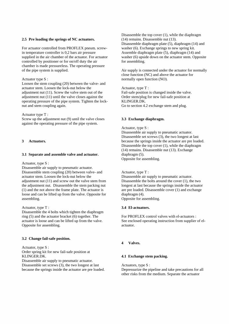
2.5 Pre loading the springs of NC actuators. For actuator controlled from PROFLEX pneum. screw-in temperature controller is 0,2 bars air pressure supplied in the air chamber of the actuator. For actuator controlled by positioner or for on/off duty the air chamber is made pressureless. The operating pressure of the pipe system is supplied. Actuator type S : Loosen the stem coupling (20) between the valve- and actuator stem. Loosen the lock-nut below the adjustment nut (11). Screw the valve stem out of the adjustment nut (11) until the valve closes against the operating pressure of the pipe system. Tighten the lock-nut and stem coupling again. Actuator type T : Screw up the adjustment nut (9) until the valve closes against the operating pressure of the pipe system. 3 Actuators. 3.1 Separate and assemble valve and actuator. Actuator, type S : Disassemble air supply to pneumatic actuator. Disassemble stem coupling (20) between valve- and actuator stem. Loosen the lock-nut below the adjustment nut (11) and screw out the valve stem from the adjustment nut. Disassemble the stem packing nut (1) and the not above the frame plate. The actuator is loose and can be lifted up from the valve. Opposite for assembling. Actuator, type T : Disassemble the 4 bolts which tighten the diaphragm ring (5) and the actuator bracket (6) together. The actuator is loose and can be lifted up from the valve. Opposite for assembling. 3.2 Change fail-safe position. Actuator, type S : Order spring kit for new fail-safe position at KLINGER.DK. Disassemble air supply to pneumatic actuator. Disassemble set screws (3), the two longest at last because the springs inside the actuator are pre loaded.
Disassemble the top cover (1), while the diaphragm (14) remains. Disassemble nut (13). Disassemble diaphragm plate (5), diaphragm (14) and washer (6). Exchange springs to new spring kit. Assemble diaphragm plate (5), diaphragm (14) and washer (6) upside down on the actuator stem. Opposite for assembling. Air supply is connected under the actuator for normally close function (NC) and above the actuator for normally open function (NO). Actuator, type T : Fail-safe position is changed inside the valve. Order stem/plug for new fail-safe position at KLINGER.DK. Go to section 4.2 exchange stem and plug. 3.3 Exchange diaphragm. Actuator, type S : Disassemble air supply to pneumatic actuator. Disassemble set screws (3), the two longest at last because the springs inside the actuator are pre loaded. Disassemble the top cover (1), while the diaphragm (14) remains. Disassemble nut (13). Exchange diaphragm (5). Opposite for assembling. Actuator, type T : Disassemble air supply to pneumatic actuator. Disassemble the bolts around the cover (1), the two longest at last because the springs inside the actuator are pre loaded. Disassemble cover (1) and exchange diaphragm (4). Opposite for assembling. 3.4 El-actuators. For PROFLEX control valves with el-actuators : See enclosed operating instruction from supplier of el-actuator. 4 Valves. 4.1 Exchange stem packing. Actuators, type S : Depressurize the pipeline and take precautions for all other risks from the medium. Separate the actuator

from the valve (see section 3.1). Exchange stem packing. Opposite for assembling. Actuator, type T : Depressurize the pipeline and take precautions for all other risks from the medium. Separate the actuator from the valve (see section 3.1). Disassemble diaphragm (4), diaphragm plate (3), spring (7), spring plate (8), set screw (9), sealing nut, nut for actuator bracket and actuator bracket (6). Exchange stem packing. Opposite for assembling. 4.2 Exchange stem packing and body gaskets. A complete valve packing kit consists of a stem packing which is exchanged according to section 4.1. Additionally the valve packing kit consists of : - A bottom gasket between valve body and bottom
plug / -cover. - An upper part gasket between valve body and
valve upper part. - Possible a upper cover gasket between valve body
and valve upper cover. 4.3 Exchange stem and plug. It is recommended to exchange complete valve packing kit in connection with exchange stem and plug. Stem and plug is looked on as one component. While valve body and valve upper part is separated, draw out the old stem downward and insert the new stem. Remarks ! The spring of the actuator, type T always move the stem upwards from the valve body by falling or failing air pressure. For normally closed valve (NC) the plug is places under the valve seat and for normally open valve (NO) the plug is places above the valve seat. For normally closed valve (NC) with actuator, type T holds good that the bottom plug / - cover is disassembled and the stem and plug is drawn out from the valve before the valve body and the valve upper part is separated. For valve with actuator, type T, the fail-safe position is changed by ordering stem and plug for the new fail-safe position by KLINGER.DK. Is the valve body connection for bottom- and upper part different from
each other, new bottom- and upper part must also be ordered. In those cases always contact technician at KLINGER.DK. Turn the valve body like that, the new plug also closes against the machined side of the seat and assemble the parts. 4.4 Reduction of kvs-value. PROFLEX valves is delivered as standard with the biggest kvs-value for the mentioned dimension (DN). If the kv-requirement is essentially smaller than 3 (which is the smallest standard kv-value in DN 15) or if a reduced kv-value is wished in a certain dimension, the valve can be offered with reduced kvs-value. 4.5 Types of plugs PROFLEX globe control valves can be delivered as metal seated, rubber seated for water or PTFE seated for steam. By correct calculation of the actuator and correct setting of the positioner, the PROFLEX globe control valves can be delivered tight closing. 5 Pneumatic screw-in temperature controllers. 5.1 Applications and principles. (enclosure 6) PROFLEX temperature controller is a screw-in temperature element with a pneumatic proportional controller. PROFLEX temperature controller is used as temperature transmitter and pneumatic proportional controller in one simple unit. Together with PROFLEX control valves with pneumatic diaphragm actuators, type S or T, a complete temperature control loop can be made. PROFLEX temperature controller is available as direct acting (T105) or reversed acting (T106). In this way, it is possible to make solutions with PROFLEX temperature controller in connection with heating as with cooling and for normally closed valves (NC) as for normally open valves (NO).
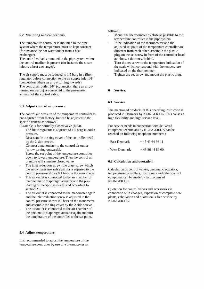
5.2 Mounting and connections. The temperature controller is mounted in the pipe system where the temperature must be kept constant (for instance the hot water outlet from a heat exchanger). The control valve is mounted in the pipe system where the control medium is present (for instance the steam inlet to a heat exchanger). The air supply must be reduced to 1,5 barg in a filter-regulator before connection to the air supply inlet 1/8” (connection where an arrow turning inwards). The control air outlet 1/8” (connection there an arrow turning outwards) is connected to the pneumatic actuator of the control valve. 5.3 Adjust control air pressure. The control air pressure of the temperature controller is pre-adjusted from factory, but can be adjusted to the specific control as follows : (Example is for normally closed valve (NC)). - The filter-regulator is adjusted to 1,5 barg in outlet
pressure. - Disassemble the ring cover of the controller head
by the 2 side screws. - Connect a manometer to the control air outlet
(arrow turning outwards). - Screw the set point of the temperature controller
down to lowest temperature. Then the control air pressure will simulate closed valve.
- The inlet reduction screw (the brass screw which the arrow turns inwards against) is adjusted to the control pressure shows 0,1 bars on the manometer.
- The air outlet is connected to the air chamber of the pneumatic diaphragm actuator and the pre-loading of the springs is adjusted according to section 2.5.
- The air outlet is connected to the manometer again and the inlet reduction screw is adjusted to the control pressure shows 0,2 bars on the manometer and assemble the ring cover by the 2 side screws.
- The air outlet is connected to the air chamber of the pneumatic diaphragm actuator again and turn the temperature of the controller to the set point.
5.4 Adjust temperature. It is recommended to adjust the temperature of the temperature controller by use of a thermometer as
follows : - Mount the thermometer as close as possible to the
temperature controller in the pipe system. - If the indication of the thermometer and the
adjusted set point of the temperature controller are different from each other, assemble the plastic plug on the set screw in front of the controller head and loosen the screw behind.
- Turn the set screw to the temperature indication of the scale which correspond with the temperature indicated on the thermometer.
- Tighten the set screw and mount the plastic plug. 6 Service. 6.1 Service. The mentioned products in this operating instruction is produced in Denmark by KLINGER.DK. This causes a high flexibility and high service level. For service needs in connection with delivered equipment technicians by KLINGER.DK can be reached on following telephone numbers : - East Denmark + 45 43 64 66 11 - West Denmark + 45 86 44 80 00 6.2 Calculation and quotation. Calculation of control valves, pneumatic actuators, temperature controllers, positioners and other control equipment can be made by technicians of KLINGER.DK. Quotation for control valves and accessories in connection with changes, expansion or complete new plants, calculation and quotation is free service by KLINGER.DK.

ENCLOSURE 1
Component listComp. Description
1 Stem packing nut2 Stem packing3 Upper part4 Bolt5 Upper part gasket6 Upper cover gasket7 Nut8 Bottom plug9 Lock-nut10 Stem11 Stem packing spring12 Frame plate nut13 Upper cover14 Plug lock-nut15 Metal seated plug (DN 15 - DN 25)16 Body17 Seat18 Metal seated plug (DN 32 - DN 150)19 Soft seated plug (DN 15 - DN 25)20 Soft seated plug (DN 32 - DN 150)21 Perforated plug for reduced kvs-value
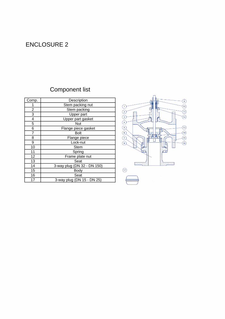
ENCLOSURE 2
Component listComp. Description
1 Stem packing nut2 Stem packing3 Upper part4 Upper part gasket5 Nut6 Flange piece gasket7 Bolt8 Flange piece9 Lock-nut10 Stem11 Spring12 Frame plate nut13 Seat14 3-way plug (DN 32 - DN 150)15 Body16 Seat17 3-way plug (DN 15 - DN 25)

ENCLOSURE 3Pneumatic diaphragm actuator, type T
Component listComp. Description
1 Cap2 Nut3 Diaphragm plate4 Diaphragm5 Diaphragm ring6 Actuatorbody7 Spring (13/42/26)8 Spring plate9 Adjustment nut10 Spring (13/42/26)
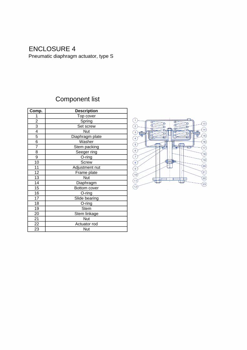
ENCLOSURE 4Pneumatic diaphragm actuator, type S
Component listComp. Description
1 Top cover2 Spring3 Set screw4 Nut5 Diaphragm plate6 Washer7 Stem packing8 Seeger ring9 O-ring10 Screw11 Adjustment nut12 Frame plate13 Nut14 Diaphragm15 Bottom cover16 O-ring17 Slide bearing18 O-ring19 Stem20 Stem linkage21 Nut22 Actuator rod23 Nut

ENCLOSURE 5
Mounting location of the linear actuators or valves
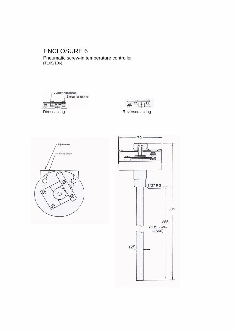
ENCLOSURE 6Pneumatic screw-in temperature controller(T105/106)
Direct acting Reversed acting