proflo pfi having packing, rod or cylinder wear problems ... cpi - proflo pfi flye… · part...
TRANSCRIPT

proflo PFIPatent Pending
Pro�o R
6 T
9 T
9 T
Divider Block Monitorand Compressor
Shutdown Protection
PROFLO
Monitors Operation of ALEMITE - LINCOLN- TRABON - - LUBRIQUIP - SB - DROPSA Divider Block Systems
The proflo must be installed with the correct magnet assembly for each divider block manufacturer
Alemite, SB & TrabonPart #0-PF-TMA w/ O-ring
DropsaPart #0-PF-DMA - ¼" BSP
LincolnPart #0-PF-LMA- w/ O-ring
PROFLO
INSTALLATION PROCEDURE FOR proflo MODEL PF1 1. Loosen all Allen head set screws (2) (A) on top of proflo case and remove magnet
housing (C). 2. Remove end plug (D) from end of divider valve where proflo will be installed. The
proflo may be installed on any convenient divider valve, top to bottom or on either side.
3. Be sure 0-ring (F) is in place on proflo magnet housing (C). Screw magnet housing (C) into end of divider valve (E).Torque to 15 foot pounds max.
4. Slide proflo the way on magnet housing (C). Do Not overtighten set screws. 15 inch pounds max.
5. The LCD on the proflo indicates cycle time. Correct operation of the proflo can be verified by the compressor running or by manually pumping oil through the divider valve assembly with a hand purge gun. The LCD enables the operator to adjust the lubricator pump for correct cycle time. Recommended cycle time can be found on a tag on top of the lubricator box or by contacting the compressor manufacturer or the engineer who designed the lube system. If cycle time cannot be identified, contact CPI.
6. NOTE: All conduit and connections should be appropriate for area classification. 7. After installing the proflo or performing any maintenance on the lube system,
compressor cylinders or packing, it is necessary to pre-lube the complete system with a purge gun to purge air from the divider blocks and all components -------- “BEFORE COMPRESSOR START-UP”
Having Packing, Rod or Cylinder Wear Problems? Ask about the proflo “Single
Point Test Kit” to test the reliability of the divider block
or lube pump at each injection point.
Instructions for Replacing the “AA” Alkaline Batteries Remove Phillips screws (6) located on battery cover on back of the proflo case. Remove cover to expose batteries. NOTE: Remove the plastic sleeves covering old batteries and slide plastic sleeves on new batteries before installation. After Inserting new batteries press the mode button until LCD displays “BATTERY”. This tells the proflo to check battery power and reset to actual remaining battery power. Replace battery cover, screws and gasket. Do Not over tighten screws. NOTE: If screws on battery cover are lost, replace with 4/40 x 3/16 phillips pan head machine screws.
WARNING - EXPLOSION HAZARD - DO NOT DISCONNECT OR CHANGE BATTERIES WHILE CIRCUIT IS LIVE. BATTERIES MUST ONLY BE CHANGED IN A NON-HAZARDOUS AREA.!
WARNING: WELDING ON THE COMPRESSOR SKID OR PIPING WITH THE PROFLO WIRING CONNECTED TO ANYTHING WILL DESTROY THE PROFLO ALARM CIRCUIT OR CAUSE THE UNIT TO FAIL PREMATURELY. THIS WILL VOID THE PROFLO WARRANTY!!
CPI Worldwide Headquarters - 4410 Greenbriar Drive, Stafford, TX 77477, USA
tel: 281 207 4600 or 800 675 6646 fax: 281 207 4612
email: [email protected] www.c-p-i.com
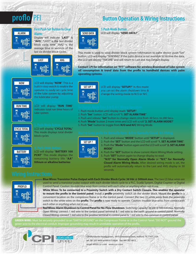
Button Operation & Wiring Instructionsproflo PFI
PROFLO
First Push Set Button to Clear Alarm: Display will indicate “LAST“ & “AVG”. “LAST” is the last divider block cycle time. “AVG” is the average time in seconds of the last six divider block cycles.
1. Push Mode Button:LCD will display “NOW”. This is a built in stop watch to enable the operator to easily set cycle time of the lube system by adjusting the lubricator pump
2. Push Mode Button: LCD will display “RUN TIME” Indicates total run time hours of lube system
3. Push Mode Button: LCD will display “CYCLE TOTAL” This mode displays total divider block cycles
5.Push Mode Button: LCD will display “SEND DATA?”
6. Push Mode Button: LCD will display “SETUP?” In this mode you can set the alarm shutdown time & change the wiring mode to N/O or N/C
Wiring InstructionsBlue Wires: Transistor Pulse Output with Each Divider Block Cycle: 36 Vdc @ 500mA max. The two (2) blue wires are used to send a transistor pulse output with each divider block cycle to a PLC, Scada System, Digital Counter or Digital Control Panel. Caution: Insulate blue wires from contact with each other or anything when not in use.White Wires: To be connected to a Proximity Switch with a Dry Contact Switch Closure. This enables the operator to mount the proflo in the control panel. Install a proflo proximity switch on the divider block. Mount the proflo in a convenient location on the compressor frame or in the control panel. Connect the two (2) white wires from the proximity switch to the white wires on the proflo. The proflo is now ready to operate. Caution: Insulate blue wires from contact with each other or anything when not in use.Red Wires: Alarm Shutdown to Control Panel for No-Flow Shutdown. Switching Capacity: 36 Vdc @ 500 mA max. Normally Open Wiring: connect 1 red wire to the control panel terminal & 1 red wire to the earth ground in control panel. Normally Closed Wiring: connect 1 red wire to the positive terminal in control panel & 1 red wire to the common in control panel.
ALARM
NOW
RUN TIME
CYCLE TOTAL
SEND DATA
SET UP ?
SET UP ?
LAST AVG
BATTERY4. Push Mode Button: LCD will display “BATTERY 100 PCNT” This mode displays the remaining battery life “AA” lithium or alkaline batteries
This mode is used to send divider block system information to palm device: push “Set” button, LCD will display “SENDING”. If the palm device is not available to receive the data, the LCD will display “FAILURE” and will return to Last and Avg Default display.
Contact CPI for information on “FFT” software for wireless download of lube system oil consumption & trend data from the proflo to handheld devices with palm operating systems.
To Change Alarm Time & N/O-N/C Wiring Operation1. Push mode button until display reads “SETUP?2. Push “Set” button, LCD will scroll “1. SET ALARM TIME”3. Push and release “Set” button to change alarm time from 30 Secs. to 240 Secs.4. Push “Mode” button 2 more times and LCD will scroll “2. SET ALARM MODE?”5. Push “Set” button to toggle from N/O and N/C Wiring Mode.
How to Setup proflo for Normally Open -N/O or Normally Closed -N/C Wiring1. Push and release “MODE” button until “SETUP” is displayed.2. Push the “SET” button and the LCD will scroll “1. SET ALARM TIME”.3. Push the “Mode” button again and the LCD will scroll “2. SET ALARM
MODE”4. Push the “SET” button to show current Alarm Wiring Mode setting.5. Push “SET” button again to change display to read: “N/O” for Normally Open Alarm Mode or “N/C” for Normally
Closed Alarm Wiring Mode. After desired wiring mode is set, the proflo will automatically return to the Last and AVG display in 30 seconds.
GREEN WIRE: Must be securely grounded to an “EARTH GROUND” on the Compressor Frame or in the Control Panel. “DO NOT” ground the green wire to the electrical conduit. Improper grounding may result in unreliable operation of the proflo.
Patent Pending
CPI Worldwide Headquarters - 4410 Greenbriar Drive, Stafford, TX 77477, USA
tel: 281 207 4600 or 800 675 6646 fax: 281 207 4612
email: [email protected] www.c-p-i.com